


THE MANUFACTURE OFIRON AND STEEL

A GOOD BOOK ON FORGINGAND STAMPING MILD STEEL
Forging, Stamping and General Smithing. AReference Book for Foreman Smiths, Managers, and Engineers,
giving fully dimensioned Drawings, Times of Making and Finished
Weights of over 600 Common types of Mild Steel Forgings and
Stampings, actually executed under the supervision of the Author.
By Benjamin Saunders, Practical Foreman Smith. 728 illus.,
ix plus 428 pp., 8vo. 245. net. Postage 6d.;abroad gd.
Preface Safety Valve 6-in. Throttle Valve 8-in. Throttle Valve Cross Barsand Pillars for Valves Drop Valves Swedges for Cross Bars Steam ReverserSteam Winch (6-in. cylinder, 8-in. stroke) Steam Winch (8-in. cylinder, lo-in.
stroke) Hauling Engines (n-in. cylinder, 2i-in. stroke) Winding Engines (24-in.
cylinder, 48-in. stroke) Winding Engines (36-in, cylinder, 6-ft. stroke) Straps or
Rings of Wrought Iron or Mild Steel Cross Heads and Piston Rods Lever for
Valve Motion Joints Eccentric Rods Pump Forgings Levers Split Joint
Pump Rod Ends Coupling Sockets for Wire Ropes Brakes for pair of 26-in.
by 5-ft. Winding Engines Forgings for 9-ft. Fly Wheel Fallers for CollieryHand, Side and Balance Levers Connecting Links and Keys Sword BucketRod Smith's Hearth Bevel Hoops and Segments Table of Weights of CraneChains Table of Sixes of Hooks for Sling Chains Hooks for Sling ChainsEccentric Rod and Bolster for Forging same Fork Lifting-out Lever Method of
Forging Fork Levers Connecting Rods and Dies for Stamping same Bolts
Tables of Weights and Times of Making of Round-necked, Square and HexagonBolts Table of Weights and Times of Making for Wrought Iron Rings Iron andSteel Rings and Methods of Forging Iron Hoop for Cast Iron Crank AngleRings and Method of Making Dies for working Sheet Metal Cast Steel Rings,Table of Weights and Times of Making Bolt Ends Tie Rods for Roof Work-Connecting Rod End Levers, Screws and Straps for Friction Clutch Strap,Saddle and Loop Cage for Hoist Single Deck Pit Cage for Colliery Hangersfor Colliery Pit Cage Double Deck Cage for Colliery Repairs to HydraulicStandard Motion Link for Steam Engine -Wrought Iron Arm for Winding DrumHook and Cross Bar for same Steam Hammer Rod Table of Times for
Welding 12-ft. to 24-ft. Shafts of from 2-in. to 5$-in. diameter Collars on Shafts
Table of Times for Welding on and Making Collars on Shafts ConnectingRod Knock-off Joint Briquette Machines Table of Weights and Times of
Making of Forgings for Winding Engines (20-111. cylinder, 4-ft. stroke) Scrapersfor Briquette Machines Winding Engines (26-in. cylinder, 4-ft. stroke) -WindingEngines (42-in. cylinder, y-ft. stroke) Steam Brake for Pair of Winding EnginesLime Washing Brick Hearth (time and cost of Building) 8-cwt. Open Frame
"Massey's" Steam Hammer (time and method of fixing) Details of Forgings for
Double Deck Cage for Colliery Cast Steel (method of welding) Diagonal Stayfor Colliery Cage Method of Estimating Cost of Labour.
DROP FORCINGS AND STAMPINGS. Eye for Rope Clip, with Dies Links for
Rope Clips, with Dies Dies for Stamping Eyes Blocks for Welding Links EyeBolts with Dies Draw Hooks for Colliery Tubs, with Dies Block for StampingEye Bolts, Turn Buckles and Swivels Single and Double-ended Spanners Diesfor Stamping Levers Dies for Stamping Joints Wrought Iron Eccentric Rods,with Dies Centres for Brick-making Machine Alternative Methods of MakingEccentric Rods Method of Making Joints Method of Making Fork Levers Diesfor Stamping Joints Wrought Iron or Mild Steel Swedges Method of StampingCross Bars Dies for End and Centre Bosses of Cross Bars Cast Steel Blocks for
finishing Cross Bars Brake Spindle End for Railway Waggon Method of
Stamping V Hanger for Railway Waggon etc., etc.
E. & F. N. SPON, Ltd., 57 Haymarket, LONDON, S.W. 1.

THE MANUFACTURE OFIRON AND STEEL
A HANDBOOK FOE
ENGINEERING STUDENTS, MEECHANTS
AND USEES OF IEON AND STEEL
BY
H. R. HEARSON, M.I.MEcn.E,
TWENTY-ONE ILLUSTRATIONS
SECOND EDITION
E. & F. N. SPON, LTD., 57 HAYMARKET, S.W.I
1922

T <r-7 / /
: METALLOGRAPHY,ALUMINIUM, BRASS, Etc.
Metallography Applied to Siderurgic ProductsAwarded a prize by the Royal Lombard Institute of Science andLiterature. By Humbert Savoia, C.E., Assistant Lecturer in
Metallurgy at the Royal Superior Technical Institute in Milan.
Translated by R. C. Corbet, Board of Trade. 94 illus., 180 pp.,cr. 8vo. 6s. net. Postage 40!.
Historical Notes Preparation of Samples The Microscope MetallographicExamination Iron and its Alloys Components of Ferro-carbon Alloys Diagramof the Equilibrium of Ferro-carbon Alloys Micro-structure of Iron Carbon Steel
Ternary Steel Quarternary Steel Cast Iron Malleable Cast Iron.
The Manufacture of Aluminium. By J. T.
Pattison, F.C.S. 18 illus., viii plus 104 pp., cr. 8vo. ys.6d.net.Postage 4d ;
abroad 6d.
Preface Historical Survey of Processes Occurrence of Aluminium Man-ufacture of Carbon Electrodes -Manufacture of Pure Alumina Founding of
Aluminium Alloys of Aluminium Uses and Application of Aluminium ANALYSISAND EXAMINATION OF ALUMINIUM WORK MATERIALS: Bauxite; Red Mud;Purified Alumina
; Cryolite ;Furnace Flux
;Oil Coke
; Pitch, and Carbon Elec-
trodes;Producer Gas and Coal
;Metallic Aluminium ; Aluminium Alloys : TABLE
OF PHYSICAL AND MECHANICAL PROPERTIES OF ALUMINIUM INDEX.
Wire and Sheet Gauge Tables. A MetalCalculator and Ready Reckoner for Merchants and for Office and
Shop use in Sheet Plate and Rod Mills and Forges. ContainingEnglish, Metric and Foreign Wire and Sheet Gauge Tables; with
net and gross divisors for finding Net and Working Weights,Allowances for Mill Scrap, etc., etc. With Worked Examplesand Weights of all Sections of Ptecious and Common Metals; also
English and Metric Weight and Measure Tables with Equivalents.
Compiled by Thomas Stobbs, Sheffield, xx plus 96 pp., cr. 8vo.
5s. net. Postage 4(i. ; abroad 6d.
Brass Founders' Alloys. A Practical Handbookcontaining many useful Tables, Notes and Data for the guidance of
Manufacturers and Tradesmen, together with Illustrations and
Descriptions of Approved Modern Methods and Appliances for
Melting and Mixing the Alloys. By John F. Buchanan, BrassFounder. 23 illus.. 129 pp., cr. 8vo. 6s. net. Postage 4d.;abroad 6d.
Introduction Uses and Characteristics of the Common Metals Some Pecu-liarities of Alloys Common Methods of Making Alloys Brassfounders AlloysBell Founders' Alloys The Modern Alloys Miscellaneous Alloys and TablesIndex.
E. & F. N. SPON, Ltd., 57 Haymarket, LONDNN, S.W. I.

CONTENTS.
CHAPTER PAGE
PREFACE TO SECOND EDITION . . . . vii
EXTRACT FROM PREFACE TO FIRST EDITION . . VUl
I. CHEMICAL ELEMENTS IN IRON AND STEEL . . 1
II. IRON ORES . . . . . .6III. THE BLAST FURNACE . . . . .9IV. THE MANUFACTURE OF WROUGHT IRON . . .22V. THE MANUFACTURE OF STEEL . . . .27VI. THE SIEMENS-MARTIN OR OPEN-HEARTH PROCESS . 38
VII. THE BASIC OPEN-HEARTH PROCESS . . .50VIII. THE ACID BESSEMER PROCESS . . . .58IX. THE BASIC BESSEMER PROCESS . . . .66X. OIL COMBUSTION AND ELECTRIC FURNACES . . 76
XI. THE TREATMENT OF STEEL INGOTS . . .79XII. EFFECTS OF ADDING OTHER METALS TO STEEL . . 88
XIII. MECHANICAL TESTING OF STEEL . . .92XIV. HEAT TREATMENT OF STEEL .... 101
INDEX . 110


PREFACE TO SECOND EDITION
THE First Edition has been generally revised, and the
chapter on CiHeat Treatment of Steel" slightly ex-
tended. As this most important operation in the
manufacture of steel admits of such a large number of
varied applications according to the qualities of steel
under treatment, it is considered that the subject is
too vast to be more than lightly touched upon within
the intended scope of this little volume.
Attention is drawn to the revised note on Titanium
(page 90), as this metal is becoming of increasing
importance in the manufacture of steel.
H. R HEARSON.
LATE OF MINISTRY OF MUNITIONS, Gux DEPARTMENT,
LONDON, 1922.

EXTEACT FROMPREFACE TO FIRST EDITION
THE object ot this book is to give a brief and simple
outline of the principle operations in connection with
the manufacture of iron and steel. Some information
concerning this great industry may be interesting to
all, and useful to those commercially connected with
iron and steel. Engineering students who have oppor-
tunities of seeing iron and steel manufactured may finH
that this outline will enable them to understand easily
the work that is going on, whereby they can then
quickly acquire a practical knowledgeInstead of giving all definitions at the beginning,
technical expressions are used where necessary, and
then defined at the point where it seems most appro-
priate. Therefore, it is recommended that this book
be read through quickly at first, in order to obtain a
general idea of its contents.
H. R. HEARSON.SHANGHAI AKSKNAL, CHINA.
November, 1912.

THE MANUFACTURE OF IRONAND STEEL
CHAPTER I
CHEMICAL ELEMENTS IN IRON AND STEEL
AN element is a substance which cannot be divided into
other substances. There are about 80 elements, and
more are constantly being discovered. Each metal in
its pure state is an element, and no one metal can be
changed into another metal. For example, coppercannot be changed into tin or any other metal, tin
cannot be changed into copper ;but if copper and tin
are melted together they form an alloy which is brass.
This alloy has properties different from either copperor tin.
There are other elements which are not metals, such
as carbon, which is the chief component of all substances
that are combustible. Coal and wood are composed
chiefly of carbon. Oxygen is an element;
it is a gas,
which, mechanically mixed with nitrogen gas, forms
our atmosphere.A chemical compound is a substance formed by the
chemical combination of two or more elements. For
example, the elements oxygen gas and hydrogen gascombine chemically and form water.

IRON AND STEEL
Chemical combination takes place in definite propor-
tions of elements, a definite number of atoms of one
element entering into chemical combination with a
definite number of atoms of another element.
Each element has a definite value with regard to each
other element ; the relative values are called the atomic
weights of the elements.
The atomic weights of oxygen and hydrogen are :
Oxygen, 16; hydrogen, 1. These gases will only unite
with each other in the proportion of 16 to 1, by weight.
The formula of water is H2 ;this means that it is com-
posed of two parts, by weight, of hydrogen, and one
part, by weight, of oxygen ;so 2 Ibs. of hydrogen will
chemically combine with 16 Ibs. of oxygen to form 18
Ibs. of water. Two Ibs. of hydrogen will not entirely
combine with 13, 14, or 15 Ibs. of oxygen ; if, say, 2
Ibs. of hydrogen is mixed with 14 Ibs. of oxygen, and a
lighted match be applied to the mixture, the 14 Ibs. of
oxygen will combine with 2 x-^-f-
Ibs.(= If Ibs.) of
hydrogen, and 15f Ibs. of water will be formed: the
remaining \ Ib. of hydrogen will be in a free state as a
gas. The principal elements, with their symbols and
atomic weights, to be considered in the manufacture of
iron and steel are :
Metals
Name. Symbol.

CHEMICAL ELEMENTS IN IRON AND STEEL
Name. Symbol. Atomic Weight.
Carbon C 12
OxygenHydrogen .
NitrogenSilicon
Phosphorus .
SulphurCalcium
16
H 1
N 14
Si 28P 31
S 32Ca 40
Iron (Latin name, Ferrum) quickly combines with
oxygen to form oxide of iron.
The three oxides of iron are :
Ferrous oxide. A chemical compound of iron and
oxygen in the proportion of one atom of iron to one
atom of oxygen, represented by the formula FeO. If
there is any moisture in the air, iron will be attacked
by the oxygen, and ferrous oxide or rust will be formed
on the iron.
Ferric oxide. The combination of 2 atoms of iron
with 3 atoms of oxygen, represented by the formula
Fe2 3 .
Magnetic oxide. The combination of 3 atoms of
iron with 4 atoms of oxygen, represented by the formula
Fe3 4 .
If ferrous oxide is made to absorb more oxygen, it is
converted into ferric oxide.
If ferric oxide is heated, oxygen gas is given off and
it changes to magnetic oxide.
Manganese is a metal which is always one of the
chemical components of iron and steel. As it easily
combines with oxygen, and to some extent with sulphur,
it is useful in the manufacture of steel.
Carbon and oxygen enter into chemical combination
with each other to form the gas called carbon monoxideB2

4 THE MANUFACTURE OF IRON AND STERL
(CO), or the gas carbon dioxide (C02),the usual name
of which is carbonic acid gas.When fuel is consumed in a furnace in which there is
a plentiful supply of air, the carbon of the fuel com-
bines with the oxygen in the air and forms C02 ;if the
air supply is insufficient, the C02 ,on coming into contact
with more hot carbon, takes up one more atom of carbon
and becomes C2 2 ,or 2CO.
Such chemical actions are conveniently represented
by equations :
C + 2 C02.
Carbon and oxygen form carbon dioxide.
C02 + C C2 2= 2CO.
Carbon dioxide and carbon form carbon monoxide.
All fuel is composed chiefly of carbon, hydrogen,and compounds of hydrogen and carbon called
"hydro-
carbons."
An element is said to be "oxidised
"when it com-
bines with oxygen to form a chemical compound.A chemical compound containing oxygen is said to
be " deoxidised" when it is made to give up its oxygen.
Silicon is easily oxidised. When oxidised it is called
silica, which has the formula Si02. Silica is the most
plentiful of all substances.
Pure white sand is an example of silica. All iron
ores contain silica, and in the manufacture of iron the
silica gives up its oxygen and becomes silicon. The
greater part of the silicon is removed, but a portion
remains as a component of the iron.
The worst impurities in iron are phosphorus and
sulphur.

CHEMICAL ELEMENTS IN IRON AND STEEL 5
Too great a proportion of phosphorus makes iron
and steel brittle when cold ; it is then said to be "cold
short." The only advantages of a high percentage of
phosphorus are that in cast iron the metal more easily
retains its fluidity while being cast into a mould, so
that the castings are clean and smooth ;and that in
steel the surface can be smooth machined with greater
facility.
Too great a proportion of sulphur makes iron and
steel brittle when red-hot ;it is then said to be "
red
short."
The separate effects of increased percentages of
carbon, manganese, and silicon are briefly :
Carbon. Increased tenacity and decreased ductility.
Manganese. Increased tenacity, decreased ductility,
also rise in yield.
Silicon. Increased tenacity, decreased ductility and
rise in yield.
See definitions, page 92.

CHAPTER II
IRON ORES
ORES which are found near the surface of the earth
are"quarried," and ores at lower depths are
" mined."
Iron ore is made up of oxide of iron and other sub-
stances, which in most cases consist chiefly of silica and
clay. The "other substances" are the gangue of the
ore, and the process of smelting separates the ganguefrom the iron.
The three classes of ores are : Ferrous ores, ferric
ores and ferrous-ferric ores. They all contain phos-
phorus.
Ferrous ore, of which Cleveland Ironstone is an
example, contains iron in the form of ferrous oxide
combined with carbon, forming ferrous carbonate
(FeO,C02).
Ferric ore, such as English hematite, red and brown,contains iron in the form of ferric oxide.
Ferrous-ferric ore has the highest percentage of
iron ; it consists almost entirely of ferrous oxide and
ferric oxide. The ore called magnetite is the most
plentiful of this class, and it is found principally in
Sweden.

IRON ORES 7
PREPARATION OF ORES FOR SMELTING
All ferrous ores are heated by the process called
calcination before being smelted. Calcination changesthe ferrous oxide into ferric oxide
;carbon dioxide and
moisture are driven off and other small chemical changestake place.
Advantages of calcination. Ferric oxide is easier
to smelt in the blast furnace than ferrous oxide, as it
does not enter into chemical combination with the silica
in the ore.
The driving off of the carbon dioxide has two advan-
tages ; by containing a lesser quantity of this gas, the
gases generated in the blast furnace burn with a greater
heat, and the gases after they leave the furnace are
better for producing power in gas engines, etc.
Calcination makes the ore porous, so that it is more
quickly melted in the blast furnace by the heat passing
more easily through it.
Calcination causes a shrinkage of the ore, but the
weight of iron contained in it remains the same ; thus a
blast furnace can contain a greater weight of calcined
ore, and more iron can be smelted.
Brown hematite ores are sometimes calcined to drive
off the water and a little carbon dioxide which they
contain.
Red hematite ores are not calcined.
Ores may be calcined in open heaps on the ground,
but it is more economical in the consumption of fuel
and in the labour of handling the materials that calcina-
tion be conducted in kilns.
Fig. 1 is a section of a calcining kiln built of steel

8 THE MANUFACTURE OF IRON AND STEEL
plates and lined with firebricks. A fire is first lightedat the bottom, and ore and fuel are then charged from
the top. The fuel used is small coal, and as there is no
forced draught or chimney it burns very slowly. Verylittle fuel is needed, as additional heat is generated by
TIG. I. CALCINING KILN
the chemical action of the ferrous oxide being changedto ferric oxide. The calcined ore is withdrawn through
openings between the pillars at the bottom of the kiln.
Air is required for the combustion of the fuel and
for the oxidation of the ferrous oxide;
it is admitted
through holes at the bottom, between the pillars, and
up through a central cone.

CHAPTER III
THE BLAST FURNACE
THE process known as "smelting" is conducted in the
blast furnace at a very high temperature. The ore
is converted into pig iron, slag and gases. Fig. 2
is a sketch, partly in section, of an iron-smelting blast
furnace. It is built of steel plates and lined with
firebricks. The whole is supported on cast-iron pillars.
Internally, the furnace consists of the cylindrical "well"
or "hearth" of brickwork, at the bottom ; next to this
is the lower cone which is called the "bosh," the upper
cone is the "stack."
Ore and fuel are charged from the top of the furnace,
and the stack expands in diameter from the top to the
bottom to allow them to become loose as they descend.
The furnace is then contracted in diameter by the
bosh so that the materials may be held up until the
fuel is consumed at the bottom of the bosh. The
melted iron and slag continually drop into the well
of the furnace, from which they are tapped out.
A furnace is"tapped
"by removing a fireclay plug
from a hole which is called the "tap hole"; molten
iron then flows out.
After smelting, there is a residue from the ore, which9

10 THE MANUFACTURE OF IKON AND STEEL
is called"slag
"; this, being of lower density that is,
lighter than iron, floats on top of the iron, and it is
tapped out of the furnace through a hole called the"slag hole
"near the top of the well.
Counter**
FIG a BLAST FURNACE in Ground
The materials are charged into the furnace by means
of a cup and cone. When the lever which supports the
cone is released, the weight of the materials causes
the cone to descend, and when these are discharged into
the furnace the cone is raised by a counterweight at the
end of the lever. A rod is connected from the lever
to a piston which works in a cylinder containing oil;

THE BLAST FURNACE 11
a pipe connects the two ends of the cylinder so that oil
can flow from one side of the piston to the other. The oil
prevents the lever from being suddenly raised or lowered.
If the cone closes with a bang on to the cup, the iron
castings of which they are made may be cracked.
The air blast enters the furnace from the brick - lined
horseshoe main through tuyeres built into the brick-
work at regular intervals at the top of the well.
The combustion of the fuel and the reduction of the
ore generate a large quantity of gases, which are col-
lected at the top of the stack and passed into a large
brick-lined tube called the downcomer, thence throughthe dust catcher to culverts
which lead them to where theyare required for further use.
The dust catcher collects
the dust which is blown out
of the furnace with the gases ;
if the gases are to be . used
in a gas engine it is very
necessary that the dust be
first separated from them.
As the tuyeres are exposedto the heat of the furnace,
means must be taken to pre-
vent the iron of which they
are made from melting.
There are many kinds of
tuyeres ;one kind is shown
in fig. 3. This consists of a tapering spiral coil of
wrought -iron pipe, 1 inch diameter, with cast iron
moulded around it.
12 THE MANUFACTURE OF IRON AND STEEL
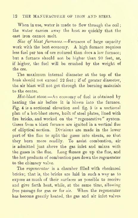
When in use, water is made to flow through the coil;
the water carries away the heat so quickly that the
cast iron cannot melt.
Size of blast furnaces. Furnaces of large capacity
work with the best economy. A high furnace requires
less fuel per ton of ore reduced than does a low furnace;
but a furnace should not be higher than 90 feet, as,
if higher, the fuel will be crushed by the weight of
the ore.
The maximum internal diameter at the top of the
bosh should not exceed 22 feet;
if of greater diameter,
the air blast will not get through the burning materials
to the centre.
Hot-blast stove. An economy of fuel is obtained by
heating the air before it is blown into the furnace.
Fig. 4 is a sectional elevation and fig. 5 is a sectional
plan of a hot-blast stove, built of steel plates, lined with
fire bricks, and worked on the"regenerative
"system.
Gases from a blast furnace are ignited in a vertical flue
of elliptical section. Divisions are made in the lower
part of the flue to split the gases into sheets, so that
they burn more readily. To assist combustion, air
is admitted just above the gas inlet and mixes with
the gases in the flue. Long flames go up the flue, and
the hot products of combustion pass down the regenerator
to the chimney valve.
The regenerator is a chamber filled with checkered
bricks; that is, the bricks are laid in such a way as to
expose as much of their surfaces as possible to receive
and give forth heat, while, at the same time, allowing
free passage for gas or for air. When the regenerator
has become greatly heated, the gas and air inlet valves

THE BLAST FURNACE 13
and the chimney valve are shut. The air-blast inlet
Hot Blast
Outlet
FIG 4-.
NOT BLAST STOVE
and the hot-blast outlet valves are then opened and
cold air from the blowing engine is admitted at the

14 THE MANUFACTUKE OF IRON AND STEEL
bottom of the regenerator. The air passes up between
the hot bricks and down the flue to the hot-blast outlet,
and thence, at a temperature of about 1500 F., to the
blast furnace. In the meantime, the gases from the
blast furnace are being burnt in a second hot-blast
stove, and when the first stove is cooled down so that
the air comes out of it at a temperature of about
1100 F., the valves are reversed. The first stove is then
reheated and cold air is heated in the second stove.
Air Inl&t From
Blowing Engine
FIG.5
HOT BLAST STOVE
Hot-blast stoves are worked in pairs or in sets of
three.
Blowing engines are large air pumps which compressair and force it under pressure to the air-blast main.
They are now generally driven by gas engines, the
engines being worked by the gases from the blast
furnace.
WORKING THE BLAST FURNACE
Fuel. Coal or coke is used as fuel according to the
prices at which each may be obtained. Bituminous
coal is either coking or non- coking. If it is suitable for
coking, it is coked for use in the blast furnace. If it is

THE BLAST FURNACE 15
not suitable, it is used without coking. Anthracite coal
may also be used. Coke is better than coal as fuel for
a blast furnace ; it burns with a more intense heat, and
it is not so easily crushed as coal is.
100 parts of bituminous coal may have an analysis
approximately as follows : Fixed carbon, 55 parts ;
hydrocarbons, etc., 35 parts ; water, 5 parts ; and ash,
5 parts.
Coke is obtained by highly heating bituminous coal
without or with very little admission of air. Water
and the free hydrocarbons of the coal are driven off.
The coke thus obtained contains a greater percentageof carbon than the original coal. Good coke has a
silvery appearance. It should be dense, but also porous ;
that is to say, the pores should be very small, otherwise
the coke will not be strong and it will be easily crushed
in the furnace. The pores allow the heat to pgfss
through the coke, so that it burns quickly and with
an intense heat.
Flux. A flux is a substance which is added to other
substances to cause them to become fluid when heated.
It must be of such chemical composition that it will,
when heated, enter into chemical combination with the
substances which are to be fluxed. It is necessary to
form from the gangue a liquid slag which may be tappedfrom the furnace.
Ores which contain a large percentage of silica require
a flux, as silica does not melt at the temperature of the
blast furnace.
Limestone is charged into the furnace as a flux;
it contains calcic carbonate (CaO,C02 ).The C02 at
oiice escapes with the blast-furnace gases, and the lime

16 THE MANUFACTURE OF IRON AND STEEL
(CaO), which is left, chemically combines with the
silica to form calcic silicate (2CaO,Si08), usually called
silicate of lime, the melting point of which is below
the temperature of the blast furnace.
If alumina (Al 2 t)is present in the ore with the
silica, the addition of limestone as a flux forms a
compound silicate of lime and alumina, which melts
at a lower temperature than calcic silicate.
Some ores are called"self-fluxing
";this means that
they contain a sufficient quantity of lime to combine
with the silica.
Other ores contain more lime than is required to
assist in the melting of the silica ; such ores can be
mixed with "non-fluxing" ores, and no limestone flux
will be needed. For example, one kind of ore maycontain 20 per cent, of silica and alumina and 4 per
cent, of lime ; this is a non-fluxing ore. Another kind
of ore may contain 10 per cent, of silica and alumina
and 18 per cent, of lime; this is a self-fluxing ore
which contains more lime than is required. If these
two kinds of ore mixed together are charged into the
blast furnace, they will be self-fluxing.
The charge is the total of materials which are putor
"charged
"into the furnace. The charge consists
of the ore, the flux and the fuel; the ore and the flux
are the burden of the furnace, and the fuel supports the
burden. The greater the burden that the fuel is
capable of supporting, the greater will be the outputof pig iron from the furnace per ton of fuel used.
Reduction of the ore. When the air blast on
entering the furnace meets the burning fuel, the oxy-
gen of the air enters into chemical union with the

THE BLAST FURNACE 17
combustible elements in the fuel and produces a
high temperature. CO gas is first produced, and this
takes oxygen from the oxides in the ore to form C02 .
The transferring of oxygen is called reduction, and
the oxide which gives up its oxygen is said to be
reduced.
Oxide of iron is thus reduced to metallic iron, which
melts and drops, together with the molten slag, into
the well of the furnace.
The iron is tapped from the furnace every 6 to
8 hours, and the slag is tapped as often as is
necessary.
Pig iron. Iron as it is tapped from the furnace is
known as pig iron;
it is allowed to flow into moulds
made in sand in front of the furnace. Each pig is about
3 feet long and weighs about 120 Ibs.
Pig iron contains carbon, silicon, phosphorus and
sulphur, which have been taken up in the process of
reduction from the materials in the charge. The term" cast iron
"should not be confused with pig iron.
Cast iron is iron which has been melted in a cupolaand cast into some definite shape.
CHEMICAL ACTIONS IN A BLAST FURNACE
The chemical actions may be represented by chemical
equations :
Reduction of ferric oxide :
Fe2 3 + SCO = 2Fe +Ferric oxide and carbon monoxide yield iron and
3C02.
carbon dioxide.
c

18 THE MANUFACTURE OF IKON AND STEEL
Reduction of manganese oxide :
Mn 8 4 + 4CO
Manganese oxide and carbon monoxide yield
3Mn + 4C02.
manganese and carbon dioxide.
Reduction of phosphorus pentoxide (phosphoric
acid) :
P2 6 + 5CO 2P
Phosphoric acid and carbon monoxide yield phosphorus+ 5C02 .
and carbon monoxide.
The silica is directly reduced by carbon, thus :
Si02 +20 Si + 2CO.
Silica and carbon yield silicon and carbon monoxide.
The two equations which follow represent the chemical
actions which cause the formation of slag :
2CaO + Si02= 2CaO,Si02.
Lime and silica yield silicate of lime.
2A12 3 + 3Si02= 2Al2 3J
3Si02 .
Alumina and silica yield silicate of alumina.
The silicate of alumina combines with six times its
weight of silicate of lime to form a compound silicate
of lime and alumina ;this compound is represented
by the formula : 2 Al2 3,3Si02 + 6(2CaO,Si02 ).This
is the main composition of some blast-furnace slags,
and it consists, approximately, of silica, 38 per cent.;
alumina, 14^ per cent.;and lime, 47^ per cent.

THE BLAST FURNACE 19
Uses of blast-furnace slag. Slag may be used
instead of stone for road-making and for railway ballast.
It may be made into cement or bricks. Slag wool (an
insulating material) is also made from it (see pp. 49,
55, 65).
QUALITY OF PIG IRON
In the selection of a pig iron for any purpose, the
quantity of phosphorus which it contains is generallythe most important consideration. Nearly all the
phosphorus in a blast-furnace charge goes into the
pig iron. If a pig iron with a small percentage of
phosphorus is required, ore, fuel and flux, which
contain little phosphorus, must, if easily procurable, be
selected.
The following table shows the composition of some
pig irons :
Component Parts. Cleveland.

20 THE MANUFACTURE OF IRON AND STEEL
much carbon and silicon, most of the carbon being
graphitic carbon.
If the burden of the furnace is heavy and at a com-
paratively low temperature, a white pig iron is produced ;
this contains less carbon and silicon, and most of the
carbon is combined carbon.
Carbon is a component of pig iron in two states as
combined carbon and as graphitic carbon. As graphitic
carbon it is not in chemical union with any other
element in the iron : it is in a free state in the form of
flakes. The other chief differences between grey pigiron and white pig iron are : Grey pig iron contains
more manganese and less sulphur, is more fluid when
melted, expands when changing from a fluid to a
solid, has a coarse grain, and is comparatively soft
and tough.
White pig iroa becomes of a pasty condition when
below its melting-point ;this condition is unfavourable
for making a clean, smooth iron casting, but it is favour-
able for"puddling
"in the manufacture of wrought iron.
White pig iron is fine-grained, hard, and brittle.
To understand what is meant by the "grain
"of a
metal, break a piece of wrought iron and a piece of
porcelain and compare the fractures. The former has
a coarse, fibrous grain ; the latter has the finest possible
grain.
Grey pig iron has a coarse grain, but not a fibrous
grain.
BLAST-FURNACE GASES
Great volumes of gases of many different kinds
mixed together are generated in a blast furnace.

THE BLAST FURNACE 21
The following table shows what the gases consist
of, and their approximate relative proportions :
Gas.

CHAPTER IV
THE MANUFACTURE OF WROUGHT IRON
Puddling. Wrought iron is produced from pig iron
or cast iron by the process of puddling, which is per-
formed in a "reverberatory
"furnace. By this process
the impurities contained in the iron are almost entirely
removed.
The change that has to be made in the compositionof pig iron is shown by comparing the composition of
Cleveland pig iron, given in the table on page 19, with
an analysis of good wrought iron.
Component Parts.

THE MANUFACTURE OF WROUGHT IRON 23
The change in the composition is effected by the"oxidation
"of the impurities. That is, the pig iron
is heated to a high temperature so that the oxygen in
the air and in the lining of the furnace shall chemically
combine with the impurities and separate them from
the iron.
The puddling process consists of melting pig iron in
a furnace and stirring, or, as it is called,"rabbling
"it,
so as to bring the whole of the molten metal into
contact with the lining of the furnace.
The furnace is lined, bottom and sides, with a
material which is called the"fettling." The fettling
is composed chiefly of oxides of iron, which, when
heated, give up their oxygen.The oxygen combines with the impurities (carbon,
silicon, manganese, phosphorus, and sulphur) in the
pig iron, and the solid chemical compounds thus formed
enter into the slag.
The gas C02 ,made by the oxidation of the carbon,
escapes to the chimney. As oxygen is given off,
metallic iron is melted away from the fettling ;some of
it mixes with the molten pig iron and some goes into
the slag. The iron in the charge is thus increased mquantity, and the fettling diminishes ; the latter has to
be continually renewed.
Oxidation is further assisted by an oxide of iron
which is put in with the charge of pig iron, and also
by the oxygen contained in the air which enters the
furnace.
Fig. 6 is a sketch of a puddling furnace.
Bituminous coal is burnt in a grate at one end, and
the flame from it strikes against and heats the sloping

24 THE MANUFACTURE OF IRON AND STEEL
roof at the other end. Heat is"reflected
"from the
roof, and the flame is" beaten back
"
by the roof on to
the pig iron.
This type of furnace is called a reverberatory furnace.
Damper
FiG.6 PUDDLING FURNACE
The word "reverberatory
"means "
beaten back." The
fuel does not come into contact with the pig iron.
FETTLING
Some materials used for fettling are :
Best tap. The cinder or slag from reheating furnaces
which are worked with basic bottoms.
Bull dog. The cinder or slag from a puddlingfurnace which has been roasted in a reheating furnace
to render it less fusible.

THE MANUFACTURE OF WROUGHT IRON 25
Purple ore, hematite ore and pottery mine are also
used for fettling.
The following table is an analysis of best tap and
bull dog :
Components.

26 THE MANUFACTURE OF IRON AND STEEL
manganese and some of the phosphorus are oxidised ;
these elements leave the pig iron and combine with
some of the melted fettling to form the slag. To quicken
oxidation, the molten metal is rabbled with an iron tool
called a "rabble."
The carbon and most of the remaining phosphorus is
now oxidised. CO gas escaping through the molten
iron to the surface gives it the appearance of boiling.
The CO gas burns with a blue flame, and, taking upmore oxygen from the air, passes away as C02.
Some slag is now tapped off. Then the temperatureof the furnace is reduced so that the iron may become
in a pasty condition;that is, not quite fluid. The iron
is separated into masses of about 100 Ibs. each, rolled
into balls, removed from the furnace and hammered
under the steam hammer. Hammering expels most of
the slag, but not all of it. The balls are shaped into
rough oblong blocks called"blooms," which are then
taken to the forge rolls to be rolled into bars of different
shapes rounds, squares and flats. If large blooms are
required, two balls are welded together under the steam
hammer.

CHAPTER V
THE MANUFACTURE OF STEEL
STEEL is a compound of iron and carbon;other elements
in small percentages only may be contained in it. The
difference between cast iron, wrought iron and steel
depends chiefly on the relative amounts of carbon in
chemical combination with the iron. The usual per-
centages of carbon are :
Metal.
Cast iron .
Wrought iron . . . . . .
Steel, mild, for ship plates and bridges
Steel, mild, for boiler plates
Steel, medium (gun steel) .
Steel, hardChisel steel .....Tool steel
Razor steel
Percentage of
Carbon.
3-25
0-04
0-15 to 0-2
0-2 to 0-25
0-3 to 0-4
0-7
1-0
1-2
1-5
If steel contains 0*5 per cent, carbon and 01 per cent,
sulphur, it is red short;
if it contains more than 0*1 per
cent, phosphorus, it is cold short. 0'03 per cent, of
phosphorus renders steel useless for cutting tools.
27

28 THE MANUFACTURE OF IRON AND STEEL
Manganese considerably mitigates the ill effects of
sulphur and phosphorus. If manganese is present in
steel, and if the steel is low in carbon, O'l per cent, of
phosphorus is permissible for some purposes. Goodrails may be made of steel containing 1 per cent,
manganese and O'l per. cent, phosphorus.Blister steel. Blister steel is made from long flat
bars, about 3 inches wide and f-inch thick, of the
purest wrought iron. The wrought iron is converted
into steel by cementation, by which process carbon is
added to the bars.
Fig. 7 shows a transverse section of cementation
furnace. The firegrate extends from the front to the
back, and two cementation boxes are placed above, one
on each side of the grate. The inner walls and arch
are built of firebricks. The cementation boxes, usually
about 15 feet long, 4 feet wide, and 3 feet deep, are
made of fire-stone slabs cemented together with fireclay.
The boxes are packed with alternate layers of charcoal
and flat bars ;the top and bottom layers are of
charcoal. All the bars must have both sides in
contact with the charcoal. The top layer of charcoal
is covered with " wheelswarf"
to prevent access
of air to the iron bars. Wheelswarf is collected
from the troughs of grindstones. When a tool is
ground on a grindstone, steel dust from the tool mixes
with the silica dust which is worn away from the
grindstone. The heat of grinding causes some of the
steel to become oxidised ; so wheelswarf is a mixture
of steel, oxide of iron, and silica. Wheelswarf melts
slightly when the furnace is in operation, and it forms
an airtight cover. The cementation boxes must be

THE MANUFACTURE OF STEEL 29
absolutely airtight. A fire is maintained in the fire-
grate so as to keep the bars heated to a bright orange
colour from six to nine days, according to the quality of
the wrought iron and to the quality of the steel which
is required to be produced.
Concrete
FIG 7. CEMENTATION FURNACE
The effect of the process is to cause carbon from the
charcoal to penetrate into the iron bars ; this is called
"carburisation
"of the iron.
When the bars are being packed, a .few bars are
placed with their ends protruding through slots at one
end of the boxes. A bar can be drawn out through
the slot, and the slot is then closed up with fireclay.

30 THE MANUFACTURE OF IRON AND STEEL
When the bar is cold, it is broken and the fracture
examined to see if carburisation has proceeded far
enough ; allowance being made for further carburisation
of the bars remaining in the boxes during the time of
the cooling of the furnace.
The bars were originally fibrous and tough ; when
taken from the boxes they are brittle and covered with
blisters. Hence the name,"blister steel." When
broken, the fracture is of a crystal appearance and
shows no fibre. The bars nearest to the firegrate are
more highly carburised than the others. None of the
bars are carburised right through to the centre, so the
centre still remains as iron. If air gains access to the
bars during carburisation or cooling, the surface becomes
oxidised ; such bars are known as"aired bars."
Single shear steel is produced by welding togethersix bars of blister steel and rolling them out to the
required shape. This makes a fairly uniform mixture
of iron and steel.
Double shear steel is produced by welding and
rolling together two bars of single shear steel ; the iron
and steel are then more intimately mixed. When the
bars are raised to a welding heat, they must be pro-
tected to prevent a loss of carbon. They are covered
with gypsum (calcic sulphate, CaS04 ),which melts in
the furnace and forms a coating on the bars.
CRUCIBLE CAST STEEL
Blister steel contains some slag, and the carbon is
not evenly distributed throughout its mass. To obtain
a homogeneous steel it is necessary to melt the blister

THE MANUFACTURE OF STEEL 31
steel. Wrought-iron bars may be converted into steel
in the crucible by an addition of charcoal or an alloy
of iron and carbon;but the best qualities of crucible
cast steel are made from blister steel. The bars of
blister steel are broken into small pieces and melted in
a small crucible made of a mixture of different kinds of
FIG 8. CRUCIBLE STEEL MELTING HOLE
fireclay. The crucible stands on a disc of fireclay and
has a lid of the same material.
A section of a steel melting hole is shown infig. 8.
Each hole contains two crucibles which are heated in
the furnace by coke fuel packed all round them. The
temperature of the furnace is regulated by means of a
brick placed in the flue at the bottom of the stack.
When the brick stops up the flue, a draught of air passes
up between the fire bars and through the furnace to the

32 THE MANUFACTURE OF IRON AND STEEL
stack. The draught is caused by the air being heated
when passing through the glowing coke. If, the brick
is removed, cold air rushes through the flue to the
stack, and the draught is lessened. With less draughtthe coke burns more slowly and less heat is givenforth.
"
JT"**
A compound containing manganese is charged into
the crucible with the blister steel. When the steel is
in the right condition to be removed from the furnace,
the crucibles are lifted with tongs, the slag is skimmed
off, and the contents poured or" teemed
"into moulds.
The moulds are of cast iron, each in two halves held
together by rings and wedges. The steel may be
prevented from adhering to the moulds by previously
exposing the inner surfaces of the moulds to the smokyflame of burning coal tar, thus covering the surfaces
with a fine deposit of soot.
Considerable experience is necessary in order to be
able to judge correctly the temperature at which to
teem the molten steel. Steel which is low in carbon
requires to be teemed at a high temperature, but as soon
as possible after it has become fluid. Steel selected
with more carbon than is required in the finished steel
requires"killing
"or
" dead melting"
that is, it is keptin the furnace for some time after it has become fluid,
until it has quieted. It should not have any ebullition
after it is teemed, or the ingot will be honeycombed
(porous).
The steel in the fluid state contains a large quantity
of gases ;such gases are called occluded gases. The
greater proportion of these gases should be separated
whilst the crucible is in the furnace, instead of after the

THE MANUFACTURE OF STEEL 33
steel is teemed. If a large quantity of gases separate
during solidification, the steel will be porous.
The quieting is effected by the reaction upon the
carbon of the iron oxide contained throughout the mass
of molten metal ; CO gas is formed and escapes. Part
of the oxide of iron is reduced and part floats to the
surface of the metal. When the evolution of gases
ceases, the metal is quiet.
If kept too long in the furnace, the steel will be
brittle on account of its having taken up too muchsilicon from the crucible.
The very small percentages of phosphorus and
sulphur contained in wrought-iron bars made from the
best Swedish pig iron are not injurious, but the steel
unavoidably receives a slight addition of sulphur which
is given off from the coke and penetrates through the
crucible. The steel, however, takes up some manganesefrom the compound of manganese charged into the
crucible, and this destroys the ill effects of the sulphur.
Ferro-manganese is the compound generally used, the
chemical action of which is shown by the following
equation :
FeO + Mn = Fe +Ferrous oxide and manganese yield iron and
MnO.oxide of manganese.
The oxide ^f iron rises to the surface of the metal
and combines with the silica of the crucible to form
manganese silicate. During killing or dead melting,
the manganese silicate is acted on by the excess carbon
in the steel, and silicon is set free.
D
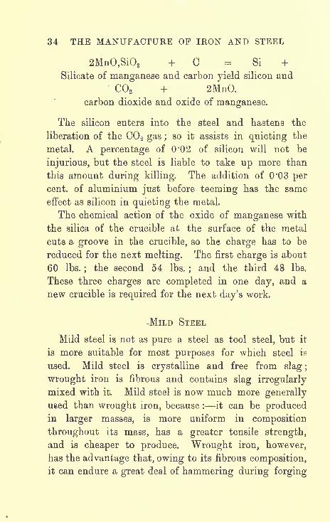
34 THE MANUFACTURE OF IRON AND STEEL
2MnO,Si02 +0 Si +Silicate of manganese and carbon yield silicon and
C02 + 2MnO.
carbon dioxide and oxide of manganese.
The silicon enters into the steel and hastens the
liberation of the C02 gas ; so it assists in quieting the
metal. A percentage of 0'02 of silicon will not be
injurious, but the steel is liable to take up more than
this amount during killing. The addition of 0'03 percent, of aluminium just before teeming has the same
effect as silicon in quieting the metal.
The chemical action of the oxide of manganese with
the silica of the crucible at the surface of the metal
cuts a groove in the crucible, so the charge has to be
reduced for the next melting. The first charge is about
60 Ibs.;
the second 54 Ibs. ;and the third 48 Ibs.
These three charges are completed in one day, and a
new crucible is required for the next day's work.
-MiLD STEEL
Mild steel is not as pure a steel as tool steel, but it
is more suitable for most purposes for which steel is
used. Mild steel is crystalline and free from slag ;
wrought iron is fibrous and contains slag irregularly
mixed with it. Mild steel is now much more generally
used than wrought iron, because : it can be producedin larger masses, is more uniform in composition
throughout its mass, has a greater tensile strength,
and is cheaper to produce. Wrought iron, however,
has the advantage that, owing to its fibrous composition,
it can endure a great deal of hammering during forging

THE MANUFACTURE OF STEEL 35
without deterioration. It may also be reheated very
many times.
ANALYSES OP MILD STEEL AN
36 THE MANUFACTURE OF IRON AND STEEL
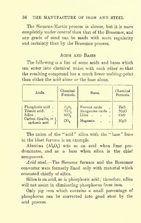
The Siemens-Martin process is slower, but it is more
completely under control than that of the Bessemer, and
any grade of steel can be made with more regularityand certainty than by the Bessemer process.
ACIDS AND BASES
The following is a list of some acids and bases which
can enter into chemical union with each other so that
the resulting compound has a much lower melting-pointthan either the acid alone or the base alone.
Acids.

THE MANUFACTURE OF STEEL 37
Basic steel. Most iron ores contain a considerable
amount of phosphorus, and, as has already been stated,
it all goes into the pig iron during smelting. Thus it
was necessary to discover some means of eliminatingthe phosphorus. The discovery of the "basic" process
by which phosphorus and sulphur can be eliminated
from some kinds of pig iron immensely increased the
production of mild steel;as pig iron, formerly useless
for steel-making, is now being converted into steel.

CHAPTER VI
THE SIEMENS-MARTIN OR OPEN-HEARTH PROCESS
THE heat in the open-hearth furnace is obtained by the
combustion of"producer
"gas.
GAS PRODUCER
Small coal is burnt in a producer and converted
into gases which can be collected and conveyed to the
furnace where they are required to be burnt. The
gases generated are carbon monoxide (CO), methane
or marsh gas (CH4 ),and hydrogen (H) ; these are all
combustible.
A gas producer is shown infig. 9. It is built of fire-
bricks with an outer covering of steel plates. The
whole structure is set on pillars over a recess which
contains water.
A fire is first lighted at the bottom, and coal is chargedinto a "hopper" at the top. Fuel is admitted to the
producer from the hopper by means of a cup and cone
arrangement, as in a blast furnace. The necessary air,
generally pre-heated, for combustion is forced in by in-
jecting steam into a pipe with an enlarged entrance. It
enters the producer through a steam and air flue and
escapes from under a central cone. The central cone38

SIEMENS-MARTIN OR OPEN-HEARTH PROCESS 39
holds up the fuel until it is consumed ; the ashes dropinto the water and are raked out. The gases ascend
and are led away by the downtake. Ammonia can be
extracted from the gases before they are led away to the
furnace to be burnt.
Hopper
FIG. 9. GAS PRODUCER
THE OPEN-HEARTH FURNACE
Fig. 10 is a vertical longitudinal section of an open-hearth furnace worked on the regenerative system. The
whole is built of firebrick and strengthened by steel
plates and old rails braced together by tie rods. The
furnace is built over four arches which are the arches of
the regenerators, one on each side for gas and one on
each side for air. The regenerators are filled with
checkered bricks in the same way as in the regenerator

40 THE MANUFACTURE OF IRON AND STEEL

SIEMENS-MARTIN OR OPEN-HEAKTH PROCESS 41
of a hot-blast stove (see page 13). The outer ones are
for air and the inner ones are for gas, but it may be
arranged that the outer ones are for gas and the inner
ones for air.
The gases and air are led from the regenerators Byflues to ports in the inner walls of the furnace.
There may be one gas and two air ports at each end of
the furnace, or two gas and three air ports. The air
ports are at a higher level than the gas ports.
The " dust pockets"are for the purpose of collecting
the dust (and sometimes slag) blown out of the furnace.
If the dust was allowed to go into the regenerators, they
would become choked.
When the furnace is at work, the gases from the
producer are led through a "duct" in the ground to
the bottom of the gas regenerator, and through the
regenerator to the gas port, or ports, in the furnace.
Air passes through another duct in the ground to the
bottom of the air regenerator, and thence to its ports in
the furnace.
The ducts, flues and ports for the gases are quite
separate from the ducts, flues and ports for the air, but
they are built in exactly the same way on each side of
the furnace. The gases and air meet and are ignited
in the furnace. As the ports are built with a slope
inwards, the flame is directed on to the metal in the
furnace.
The products of combustion pass out through the
opposite ports at a very high temperature and heat the
regenerators on the other side on their way to the
chimney.The arrows in the figure indicate the directions of the

42 THE MANUFACTURE OF IRON AND STEEL
gases and air entering the regenerators on the left side
and leaving the regenerators on the right side. Whenthe gases and air have travelled in this direction for a
certain length of time, say twenty minutes, the re-
generators on the right side will have become greatly
heated; the gas and air valves are then reversed so as
to cause the gases and air to enter the furnace throughthe opposite ports and in the opposite direction. That
is, the gases and air will be made to pass upwards
through the regenerators on the right side. The gases
and air will be heated by passing between the very hot
bricks, and when they ignite in the furnace the flame
produced will give a more intense heat than before. In
the meantime, the regenerators on the left side are being
heated by the outgoing gases.
The valves are at intervals reversed, so that the gasand air regenerators on one side and the gas and air re-
generators on the other side are alternately heated and
cooled. With each reversal the furnace becomes more
highly heated until a temperature is attained which
melts the iron.
The roof of the furnace becomes greatly heated
and reflects its heat on to the metal. The bricks of
the roof are built with an arch to prevent them from
falling in.
As the whole structure expands on being heated, the
nuts at the ends of the tie rods are gradually screwed
back. When steel-making is finished, the furnace is
allowed to cool down gradually, and as it cools, the nuts
on the tie rods are screwed up. The bottom of the
furnace consists of firebricks on steel plates supported
by girders.

SIEMENS-MARTIN OR OPEN-HEARTH PROCESS 43
LINING THE FURNACE FOR THE ACID PROCESS
The furnace is lined with white or silver saiid mixed
with a small quantity of ganister. The former is found
chiefly in Belgium ;it is almost pure silica (silica, 98J-
per cent.) and is infusible at the furnace temperature.
Ganister is found in large quantities near Sheffield ; it
contains a less percentage of silica (silica, 94|- per cent.)
than white sand, and the other materials contained in it
are fusible at the furnace temperature, so it acts as a
binding material.
A thin layer of the mixture is laid over the bottom
firebricks, and when the heat of the furnace is sufficient,
it"frits" (melts slightly) and adheres to the bricks.
The mixture is continually added in thin layers until
the bottom of the furnace has a thick lining of sand.
The grains of sand frit just sufficiently to stick to each
other.
Some acid slag is then thrown into the furnace and
melted and rabbled over the furnace bottom so as to
glaze the surface of the sand. The slag is tapped off.
Charging ike furnace. The furnace is charged with
a small quantity of pig iron and, on top of the pig iron,
scrap steel or iron. Light scrap should be kept off the
bottom and clear of the banks of the furnace, as it
quickly oxidises and would cut grooves in the silica
lining.
The furnace is not charged to its full capacity until
it has been worked for three or four days ;it should be
kept in continual operation, day and night, until repairs
are necessary. A furnace is usually worked continuously
for two and a half to three months.

44 THE MANUFACTURE OF IRON AND STEEL
If there is a large quantity of scrap steel to be dis-
posed of, a charge for a 15-ton furnace may be :- 8 tons
of pig iron, 5 tons of scrap steel, 1J tons of hematite
ore as the oxidising agent, and 2^ cwts. of ferro-
manganese at the end of the process to convert the
iron into steel.
CHEMICAL ACTIONS IN THE ACID OPEN-HEARTH PROCESS
Good acid open-hearth steel may be manufactured
from pig iron containing the following elements :
Element. Percentage.
Carbon . . . .3*5Silicon . . . .2-0Phosphorus. . . .0*05Sulphur . . . .0*05Manganese . . . . 075
In the acid process neither phosphorus nor sulphuris eliminated. In fact, the percentages are greater in
the finished steel than in the original pig iron, as the
iron when molten absorbs slight amounts of phosphorusand sulphur from the hematite ore and from the spiegel-
eisen or ferro-manganese. So phosphorus and sulphur
should not be contained in the pig iron in a greater
proportion than 0'05 per cent.
The eliminations of the impurities in the charge take
place in three stages :
1. During melting, by the oxidising action of the
flames.
2. After melting, by the action of the oxides of iron
formed during melting.

SIEMENS-MARTIN OR OPEN-HEARTH PROCESS 45
3. During boiling, by the action of the oxide of iron
added to the charge.
In the first stage,"during melting," about one-half
of the silicon and one -third of the manganese are
oxidised.
In the second stage,"after melting," nearly all the
remaining silicon and manganese are eliminated and the
carbon has been diminished. The oxidised products,
silica (Si02),oxide of manganese (MnO), and some
oxides of iron (FeO and Fe2 3) go into the slag.
At this point, a hematite ore containing 70 to 80 per
cent, of ferric oxide is charged, in small quantities at a
time, into the furnace.
In the third stage,"during boiling," nearly all the
carbon is oxidised ; the escape of CO gas through the
metal gives the appearance of boiling. If the hematite
ore is added too quickly, the ebullition may cause some
metal to run out of the furnace doors. The ferric oxide
in the ore is decomposed, and its oxygen quickens the
burning out of the carbon; the iron which separates
from it adds to the molten metal in the charge.
The chemical equation is :
30 + Fe2 3= 2Fe +
Carbon and ferric oxide yield iron and
300.
carbon monoxide.
The gas CO burns at the surface of the metal,
and, taking up more oxygen from the air, it escapes
as C02.
Before finishing, it is beneficial to place a few half-

46 THE MANUFACTURE OF IRON AND STEEL
pigs of hematite iron, containing much carbon and
silicon, just inside the doors of the furnace. When
they are red-hot, push them into the melted metal and
rabble quickly ; this will deoxidise the charge and makeit quiet for tapping.
If medium or hard steel is required, a certain
weighed quantity of spiegeleisen is now thrown into
the furnace and the charge is almost immediately
tapped.
If a mild steel is required, the iron is tappedfrom the furnace, and ferro-manganese is thrown into
the ladle at the same time as the metal flows in, or
it may be added to the charge in the furnace before
tapping.
The approximate compositions of spiegeleisen and
ferro-manganese are as follows :
Components.

SIEMENS-MARTIN OR OPEN-HEARTH PROCESS 47
To ascertain the percentage of "carbon exactly, the
sample is submitted to a chemical colour test. The
test is made as follows :
Fine drillings are taken from the sample we will
call these drillings"sample A" of exactly equal
weight to another sample which we know to contain
the percentage of carbon which we require in our
charge in the furnace. The latter sample we will call
"sample B."
Samples A and B are placed separately into two
similar test tubes, and into each tube is poured an equal
quantity by measurement in a glass tube of colour-
less nitric acid. The nitric acid dissolves the samplesof steel. The steel will be dissolved more quickly if
the test tubes are heated by lowering them into a vessel
containing boiling water.
When it is seen that the steel is all dissolved, the
colours of the solutions in the test tubes are com-
pared. The colours vary from a light straw to a dark
brown. If the solution in which sample A is dissolved
is darker in colour than the solution of sample B, it
contains a higher percentage of carbon;in which case
it will be necessary to reduce the amount of carbon
in the charge by charging more hematite into the
furnace.
If, on the other hand, solution A is lighter in colour
than solution B, it contains a lower percentage of
carbon. The percentage of carbon in the charge must
then be increased by adding spiegel or ferro.
The following table is for the purpose of showing
approximately the chemical changes that take place
during the process :

48 THE MANUFACTURE OF IRON AND STEEL
Components.

SIEMENS-MARTIN OK OPEN-HEARTH PROCESS 49
clear by referring to the table (p. 46) of the compositionsof spiegel and ferro.
500 Ibs. of spiegel contains 75 ]bs. of manganese and
25 Ibs. of carbon. -
100 Ibs. of ferro contains 77 Ibs. of manganese and
6*3 Ibs. of carbon.
To get the same quantity (75 to 77 Ibs.) of manganesein each case, 500 Ibs. of spiegel to 100 Ibs. of ferro
would have to be charged. But 500 Ibs. of spiegel
contains 25 Ibs. of carbon; therefore, it will make a
harder steel than 100 Ibs. of ferro, which contains 6*3
Ibs. only of carbon.
Slag. The following gives an idea of what may be
the composition of the slag which results from the
process :
Components.

CHAPTER VII
THE BASIC OPEN-HEARTH PROCESS
MANY kinds of pig iron contain a medium quantityof phosphorus, too much for it to be used for steel-
making by the Siemens acid process, and not enoughto enable the necessary high temperature to be main-
tained in the Bessemer basic process. Such iron can
be converted into steel by the open-hearth basic process
only.
Basic lining. The lining of the furnace is the onlymatter in which the plant for the basic process diifers
from that of the acid process. The furnace requires a
basic lining, so that the base (usually lime) which is
added to the charge of pig iron shall not enter into
chemical union with it, but shall remain free to combine
with the phosphorus as it is oxidised from the pig iron,
and to retain the phosphorus in the slag until the
process is finished.
Basic materials. The following table gives the chief
components of some basic materials after they have
undergone the process of calcination to remove C02
and other volatile matters contained in the quarried
lumps :
50

THE BASIC OPEN-HEARTH PROCESS 51

52 THE MANUFACTURE OF IRON AND STEEL
Basic material is very friable, and therefore it cannot
be used for building the walls and roof of the furnace ;
these are built of silica bricks.
Chemical action is liable to take place between the
silica bricks and the basic material ; the action is con-
siderably less if the acid and basic materials are not
subject to pressure in contact with each other.
A method of partly relieving the basic material from
FIG. II. FURNACE LINING. BASIC MATERIAL.
the weight of the walls and roof is shown in fig.11.
An anole iron is riveted on to the inside of the steelO
plates which form the furnace casing. Chemical action
is further prevented by making a joint, which is called
a neutral course, between the acid and basic materials.
The neutral course is generally a mixture of crushed
chrome iron ore and a little tar.
The iron plates at the bottom of the furnace are
covered with silica bricks, and the basic material is
fritted on to the bricks. When the furnace is in
operation, there will be no chemical action between the

THE BASIC OPEN-HEARTH PROCESS 53
bottom silica bricks and the basic lining, as sufficient
heat will not penetrate the upper lining.
Charging the furnace. The pig iron for use in the
process should not vary much from the following com-
position : Phosphorus, 175 per cent. ; silicon, not
more than 1 per cent. ; sulphur, not more than 0'06 per
cent.; manganese, 175 per cent.; and carbon, 3*5
per cent. 25 to 30 per cent, of scrap, wrought iron or
steel, may be charged with the pig iron. When the
charge is melted, lime and an oxide of iron is thrown
into the furnace. The oxide of iron may be any form
of ferrous or ferric oxide, which contains little or no
silica. Best tap, the composition of which is given on
page 25, is used, or"pottery mine," which is an iron
ore mined in Staffordshire, England.
THE CHEMISTRY OF THE PROCESS
The oxide of iron is the oxidising agent.
Oxidation of silicon :
Si + 2= Si02.
Silicon and oxygen yield silica.
Silica, which is an acid, is prevented from entering;
into combination with the basic lining of the furnace
by the highly heated lime, which is a base. The silica
at once combines with the lime and forms silicate of
lime in the slag.
2CaO + Si02= 2CaO,Si02.
Lime and silica yield silicate of lime.
Oxidation of carbon :
20 + 2CO.
Carbon and oxygen yield carbon monoxide*

54 THE MANUFACTURE OF IRON AND STEEL
The CO gas escapes through the molten metal and
gives it a motion with the appearance of boiling. Whenthe CO reaches the surface of the metal, it takes upmore oxygen from the air and escapes as C02.
Oxidation of manganese :
Mn + MnO.
Manganese and oxygen yield manganous oxide.
The manganous oxide, which is a base, enters into
the slag ;it is useful in the process, as it helps to keep
the slag more basic than acid.
Oxidation of phosphorus :
2P + 50 PA-Phosphorus and oxygen yield phosphoric acid.
The phosphoric acid combines with the lime and
remains in the slag as tetra-calcic-phosphate (phosphateof lime).
P2 5 + 4CaO = 4Ca05PA.
Phosphoric acid and lime yield phosphate of lime.
Silicon and manganese are the first to be completelyremoved from the pig iron
; carbon and phosphorusoxidise more slowly.
Small quantities of lime are added from time to time;
too much lime will cause a pasty slag which will be
difficult to tap from the furnace. The carbon should
not be removed before the phosphorus, as the CO gas
on escaping causes a commotion in the metal. This
commotion is necessary in order to bring the phos-
phorus in the metal into intimate contact with the oxide
and with the lime. Insufficient lime will cause a charge
to go"off the boil," CO ceasing to escape, before enough
phosphorus has been eliminated. In this case more

THE BASIC OPEN-HEARTH PROCESS 55
lime is added, and some hot pig iron is charged in order
to again get the metal " on the boil."
Samples are taken from the furnace at intervals, and
when they are cooled and broken it can be seen by the
appearance of the fracture to what extent the phos-
phorus has been eliminated.
At the end of the process the slag should be as non-
oxidising as possible, as, if too much oxygen is present,
the metal cannot be quietly teemed.
The elimination of much sulphur cannot be relied
upon, and for this reason a pig iron with a small per-
centage of sulphur should be selected.
Manganese, during the process, has some slight effect
in eliminating sulphur, and when the spiegeleisen or
ferro-manganese is added, there is a further small reduc-
tion of sulphur.
To convert the iron into steel, spiegel or ferro is
added as in the Siemens acid process.
It is not intended that the basic material with which the
furnace is lined shall be used as a base to absorb the acids,
silica and phosphoric acid lime is added to prevent that;
but the lining becomes gradually worn and damaged, and
new layers of basic material are occasionally required.
Slag. The slag resulting from the process will be
approximately of the following composition :
Components.

56 THE MANUFACTURE OF IKON AND STEEL
The slag is broken and ground into a fine powder for
manure.
If it contains much less lime, or much more silica or
oxide of iron than shown in the above composition, it
is dense and hard and difficult to break up into small
enough pieces for grinding.
The phosphoric acid and iime, especially the phos-
phoric acid, makes the slag valuable in some soils as a
fertiliser.
THE ACID AND BASIC OPEN-HEARTH PROCESSES
COMPARED
The chief points of difference between the acid and
basic open-hearth processes may now be summarised :
Acid. [Basic.
Furnace lined with acid material,
chiefly silica.
Hematite pig iron used.
Scrap used must contain a small
percentage only of phosphorus.-**Hematite ore used as the oxidis-
ing agent.
No elimination of phosphorus/*^
Slag useless as a fertiliser.
Furnace lined with basic material.
Phosphoric pig iron used.
Phosphoric scrap may be used.
Ore containing phosphorus maybe used, but it must contain
very little silica.
Phosphorus is eliminated.
Slag valuable as a fertiliser.
As a greater quantity of slag is produced in the
basic than in the acid process, a smaller quantity of
basic than acid steel is produced in furnaces of equal
dimensions.
A great disadvantage of the basic process is that good
high carbon steel cannot be made by it. The reason

THE BASIC OPEN-HEARTH PROCESS 57
for this is that a small percentage of phosphorus
always passes back from the slag into the metal when
ferro or spiegel is added, owing to the reducing action
of the carbon and of the manganese.
High carbon steel may be made by recarburising the
iron after it is tapped by adding molten spiegel in the
ladle ;or by the "
Darby recarburising process," which
consists of passing the metal, as it flows from the
furnace, through a perforated vessel into which falls a
stream of fine carbon. In these methods the difficulty
is to keep the slag from passing into the ladle.
The differences between mild or medium steels pro-
duced by the acid or basic open-hearth processes are
not generally shown by chemical analysis or bymechanical tests, but under microscopical examination
basic steel shows a more defective grain.
Steel produced by the basic open-hearth process is
cheaper than that from the acid open-hearth, and it is
largely used in America, Germany and Belgium. But
English manufacturers consider that while basic steel is
suitable for many requirements, it fails entirely, as
compared with acid steel, in endurance tests, when
used for tyres, angles, forgings, or for spring steel.
Even for rails, acid steel is preferred.
Experience has shown that acid steel resists"fatigue
"
(see Vanadium, page 90) better than basic steel.

CHAPTER VIII
THE ACID BESSEMER PROCESS
THE acid Bessemer process is carried out in a vessel
which is called a converter. The pig iron to be con-
verted into steel must be low in phosphorus and
sulphur, and be similar to the composition, given on page
44, of the pig iron used in the acid Siemens process.
Melted pig iron is poured into the converter, and it is
purified by blowing a large quantity of air through it;
the oxygen contained in the air is the oxidising agent.
Fig. 12 is a section of a Bessemer converter built of
steel plates and lined with firebricks and ganister. It
is charged and emptied through the one open end;at
the other end are the tuyere holes through which the
air blast is forced.
The converter is encircled at its widest part by a steel
ring, to which two trunnions are secured. The trunnions
rest on bearings and act as axles. One axle is a tube
through which the air blast passes to the bottom of the
converter.
A toothed wheel, in gear with a pinion, is secured to
the axle;as the toothed wheel is revolved, it rotates the
converter to any required position. The converter is
made up of three parts which are bolted together. The58

THE ACID BESSEMER PROCESS 59
three parts are called the hood or nose, the body, and
the bottom or plug.
LINING THE BESSEMER CONVERTER
Ganister is the material used for lining the converter ;
it consists chiefly of silica, but has other more easily
fusible materials contained in it which enables the whole
to bind ifc firmly together.
The three parts of the converter are lined separately.
The hood is inverted and a wooden core is placed within
it;the space between the core and the hood is filled arid
rammed with ganister. The bottom is also rammedwith ganister, openings being left for the insertion of
the tuyeres. The body is lined with silica bricks
cemented with ganister.
The tuyeres are tapered plugs which have been
moulded out of fireclay ; they are cemented into the
openings in the bottom of the converter with fireclay
or ganister, and are held in position by means of a
steel plate. Each tuyere has from 12 to 20 holes about
^inch in diameter.
Owing to the violence of the air blast, the bottom
lining has to be frequently repaired generally after
about 20 "blows." The hood and body may not need
relining more often than once a year.
CHARGING AND WORKING THE CONVERTER
A fire is lighted in the converter to heat it before
charging with metal. The metal may be pig iron melted
in an ordinary foundry cupola.

60 THE MANUFACTURE OF IRON AND STEEL
In this way the pig iron may be selected of a uniform
quality, and the steel manufactured from it -will also be
uniform in quality.
It is, however, much more economical in fuel and
labour to charge the converter with molten metal direct
from the blast furnace.
FIG. 12. BESSEMER CONVERTER
If the metal is taken from a single-blast furnace, it
may vary in quality, as blast furnaces often produce
irregular qualities of iron.
It is, therefore, usual to tap iron from several blast
furnaces into a large vessel which is called a mixer.
One or two furnaces may produce iron high in silicon
or sulphur, and this may be compensated for by iron from

THE ACID BESSEMER PROCESS 61
other furnaces being low in silicon or sulphur. The
iron obtained by mixing the tappings of four or more
blast furnaces is of a fairly uniform composition.The mixer is a large tipping ladle that is, a ladle
which is emptied by rotating it on its trunnions.
Metal is poured from the mixer into another tipping
ladle, which is carried on rails to the converter. As this
ladle is being filled it stands on a weighing machine, so
that the actual quantity of molten metal which it
FIGJ3 CHARGING T BESSEMER CONVERTER
contains is known; the quantity is sufficient for one" blow
"in the converter.
Before charging the converter with metal, it is rotated
to a horizontal position as shown in fig. 13. In this
position the metal cannot flow into the tuyere holes.
When the converter is charged, the air blast is
started and the converter rotated to a vertical
position.
The pressure of air, 20 to 25 Ibs. per square inch,
prevents the metal from flowing into the tuyere holes,
and the metal is kept in motion by the force of the
air. The air 'passes up through the hot fluid metal,

62 THE MANUFACTURE OF IRON AND STEEL
and, in so doing, the oxygen of the air enters into
chemical combination with the silicon, carbon and
manganese.In some converters the tuyeres are placed on one side
and slightly inclined downwards, just above the level of
the molten metal when the converter is upright ; air is
then blown on to the surface of the metal. Such con-
verters are called side-blown or surface-blown converters.
The air blast causes a roaring sound, and a long flame
issues from the opening at the top of the converter.
The flame changes in colour during the continuation of
the air blast ; first it is violet, then orange, and then a
dazzling white. After this the colour becomes of a faint
blue and the flame almost disappears the flame is then
said to"drop
"; at the same time there is a change in
the sound of the blow. This indicates that all the
carbon has been oxidised. The oxidation of the silicon
and the manganese is completed before the oxidation of
the carbon.
The converter is then immediately rotated to a hori-
zontal position and the air blast stopped.
The skg, on account of its being of lower density,
separates from the iron and rises to the surface.
The metal is now highly oxidised ; it is supposed that
at this stage free oxygen or an oxide of iron exists, dis-
solved with and clinging to the metal. Hot ferro-
manganese or spiegeleisen is now thrown into the
converter, and, as it melts, the iron is deoxidised,
receives the required percentage of carbon, and is
converted into mild or medium steel.
The steel is now teemed into moulds by further
rotating the converter.

THE ACID BESSEMEK PROCESS 63
CHEMICAL ACTIONS IN THE ACID BESSEMER PROCESS
The following table is an example of the chemical
changes that take place during the process :
Components.

64 THE MANUFACTURE OF IRON AND STEEL
A small quantity of iron is oxidised.
Fe + FeO.
Iron and oxygen yield ferrous oxide.
2Fe + 30 Fe2 3 .
Iron and oxygen yield ferric oxide.
These oxides of iron go into the slag.
When the ferro-manganese or spiegeleisen is added,
deoxidisation may be supposed to take place, thus :
FeO + Mn MnOFerrous oxide and manganese yield manganous oxide
+ Fe.
and iron.
HEAT MAINTAINED DURING A BESSEMER BLOW
The fluid metal is poured into the converter at a high
temperature, and a large quantity of cold air is forced
through it. The metal, however, is not reduced in
temperature, but it is actually hotter at the end of the
blow than at the beginning. The increase in tempera-ture is chiefly due to the burning of the carbon and the
silicon. Most of the heat evolved by the oxidation of
the carbon is carried away in the gases which escape,
but the silica resulting from the oxidation of the silicon
remains at a very high temperature in the slag. This
slag protects the metal and keeps it in a fluid condition.
It is necessary to have a certain percentage of silicon
in the pig iron to maintain the heat required for the
acid Bessemer process.
If ike metal is too hot at the finish of the process,
owing to the iron containing too great a percentage of

THE ACID BESSEMER PROCESS 65
silicon, it will be in a disturbed condition resembling
boiling when poured into the moulds, and the ingotswill be unsound.
A remedy for this is to throw some scrap iron or steel
into the converter before pouring in the melted pig iron;
the heat of the whole mass of fluid metal is thus lessened
by heat being absorbed in melting the scrap. With an
overhead shute arrangement, scrap may be thrown into
the converter during the blow.
If the metal is too cold at the finish of the process,
the ferro-manganese or spiegeleisen does not become
properly mixed with the fluid iron; the metal is not
sufficiently fluid to pour evenly into the moulds, and
some of the steel may solidify in the ladle. In this case,
iron containing more silicon should be used; or, if this
cannot be obtained, a greater volume of air blast, causingmore rapid oxidation, may produce sufficient heat.
Acid Bessemer slag contains about 9 per cent, of iron
and 12 per cent, of manganese, but, like acid Siemens
slag, the composition of which is given on page 49, it
does not pay to extract these metals.

CHAPTER IX
THE BASIC BESSEMER PROCESS
BY the basic Bessemer process good mild steel maybe made from steel containing much (2j to 3j per cent.)
phosphorus.The plant required is the same as in the acid
Bessemer process, the only difference being that the
converter is lined with basic material instead of acid
material.
The converter for the same amount of steel producedmust be of larger dimensions for the basic process than
for the acid process, as more slag results from the basic
process.
Machinery for grinding the slag into powder is also
required.
LINING THE BASIC BESSEMER CONVERTER
Dolomite, the composition of which is given on page
51, mixed with anhydrous tar, is the most generally
used basic material.
The hood, which is the least liable to be damaged, is
often liDed with a mixture of new dolomite and old
dolomite ground fine, tar being added to the mixture.
The hood is inverted and a wooden core placed within

THE BASIC BESSEMER PROCESS 67
it; the space between the core and the hood is filled
and rammed with basic material. The body is lined
with bricks which are made of compressed dolomite
and tar, and these are cemented together with dolomite
and tar. The bottom or plug is also made of the same
materials well rammed. Holes, f-inch diameter, are left
in the plug to serve as the tuyere holes for the air
blast. About 90 holes would be required for a 20-ton
converter.
After the bottom is bolted on, the space between it
and the body is filled with basic material.
The mixed dolomite and tar is always rammed with
very hot rammers, which are iron bars enlarged at
one end, and as the basic material is put on in thin
layers the heat of the rammers causes the layers
to become cemented together into a strong solid
block.
The plug quickly becomes worn out and the basic
material has to be renewed. The plug may perhaps be
used for 20 blows, the lining of the body for 100 blows,
and the lining of the hood for 200 blows.
CHARGING AND WORKING THE CONVERTER
A quantity of calcined lime, 3 to 4 cwts. per ton
of iron, is first thrown into the converter. The con-
verter is then rotated until it is in the position
shown in fig. 13, page 61, in which position it re-
ceives the charge of molten pig iron from a mixer
or cupola.
The air blast is then started and the converter
brought back to a vertical position.F2

68 THE MANUFACTURE OF IRON AND STEEL
The air blast is continued until the flame"drops,"
and for a short time after.
There is the period 13 to 15 minutes of the blow until
the flame drops, and another period 3 to 4 minutes,
which is called the "after-blow."
Nearly all the phosphorus is oxidised during the
after-blow.
When the after-blow is considered to be sufficient,
the converter is rotated to a horizontal position aud the
air blast stopped.
After allowing a short time for the slag to separate
from the iron, a sample of the metal is taken from
the converter by means of a long-handled spoon ;
this is solidified in an open mould, hammered flat,
cooled with water, and broken. By the appearanceof the fracture it may be judged whether or not the
metal is sufficiently free of phosphorus ;if high in
phosphorus, long bright crystals will be shown in the
fracture.
If the metal contains too much phosphorus, the
blow will have to be restarted for a short time and
then another sample taken and examined.
If the examination of the sample .is satisfactory, as
much as possible of the slag is quickly poured off,
and the process is finished by the addition of ferro-
manganese or spiegeleisen to the iron to convert it
into steel.
CHEMICAL ACTIONS IN THE BASIC BESSEMER PROCESS
The following table is an example of the chemical
changes that take place during the process :

THE BASIC BESSEMER PROCESS 69
Components.

70 THE MANUFACTUKE OF IRON AND STEEL
necessary in the blow. Great heat is produced by the
oxidation of the phosphorus, and, as little . is oxidised
until the beginning of the after-blow, the greatest heat
is obtained during the after-blow. Great heat is neces-
sary for the elimination of the phosphorus and the
sulphur. It is desirable to have a larger percentage of
manganese in the pig iron for the basic process than
for the acid process. It is oxidised from the commence-
ment of the blow, and the heat of oxidation makes upto some extent for the percentage of silicon being low.
As manganous oxide, which is formed by the oxida-
tion of manganese, is a base, less lime is required if
there i a large percentage of manganese.
Sulphur is nearly all oxidised during the after-blow,
when there is an excess of ferric oxide, a high tempera-ture of metal, and a fluid slag.
If the percentage of sulphur in the pig iron is high,
say 0*3 per cent., about 70 per cent, of it may be
removed; if the percentage is 0'09, about 30 per cent,
may be removed;
if the percentage is only 0'05, there is
usually none of it removed. If exceptionally pure lime,
containing not more than 0*5 per cent, of silica and only
traces of sulphur, is used, the sulphur in the finished
steel may be reduced as low as 0*03 per cent.
A small percentage of phosphorus passes back from
the slag into the metal when ferro-manganese or spiegel-
eisen is added, the phosphorus in the slag being
reduced by the carbon and the manganese. The agita-
tion caused by the production of CO gas, when ferro or
spiegel is added, throws the metal into intimate contact
with the slag, and assists the reduction of the phos-
phorus. This reduction is called the"rephosphorisa-

THE BASIC BESSEMER PROCESS 71
tion"of the metal, and, in order to lessen the reactiou,
as much as possible of the slag is poured off before
adding ferro or spiegel.
If mild steel is required, ferro-manganese is chargedinto the converter
;for medium or hard steel, molten
spiegeleisen is added in the ladle. At the end of the
after-blow the metal is highly oxidised, and before
adding the ferro or spiegel it is often partly deoxidised
by charging red-hot, grey, hematite pig iron, rich in
carbon and silicon, into the converter.
The chemical reactions are shown by the following
equations :
As in the acid Bessemer process, the elements which
are required to be removed from the pig iron are
oxidised by the oxygen contained in the air forced
through the molten metal.
C + CO.
Carbon and oxygen yield carbon monoxide,
C + 2 C02 .
Carbon and oxygen yield carbon dioxide.
JThe gases CO and C02 escape into the air.
Si + 2= Si02 .
Silicon and oxygen yield silica.
Silica and lime form silicate of lime, which remains in
the converter as slag.
2CaO + Si02 2CaO,SiOiLime and silica yield silicate of lime.
Mn + MnO.
Manganese and oxygen yield manganous oxide.
The manganous oxide enters into the slag and helps to
keep the slag basic.

72 THE MANUFACTURE OF IRON AND STEEL
S + 2 S0 2 .
Sulphur and oxygen yield sulphur dio,xide.
The sulphur dioxide is a gas, and it escapes to the air.
Oxides of iron are formed, and they also enter into the
slag.
Fe + FeO.
Iron and oxygen yield ferrous oxide.
2Fe + 30 Fe2 3 -
Iron and oxygen yield ferric oxide.
'Sulphur trioxide is formed by the action of ferric oxide.
9Fe8 8 + S 6Fe 3 4 + S03.
Ferric oxide and sulphur yield and
The sulphur trioxide combines with lime in the slag.
S03 + CaO = CaS04 .
Sulphur trioxide and lime yield calcic sulphate.
Nearly all the sulphur eliminated from the pig iron
goes into the slag.
2P + 50 P2 5 .
Phosphorus and oxygen yield phosphoric acid.
The phosphoric acid combines with the lime and
remains in the slag as phosphate of lime.
P2 5 + 4CaO = 4CaO,P2 5 .
Phosphoric acid and lime yield tetra-calcic-phosphate
or phosphate of lime.
BASIC BESSEMER SLAG
The slag resulting from the basic Bessemer process is
of much value as a fertiliser, because it contains a high
percentage of phosphorus.
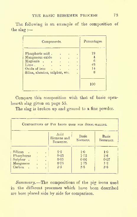
THE BASIC BESSEMER PROCESS 73
The following is an example of the composition of
the slag :
Components.

74 THE MANUFACTURE OF IRON AND STEEL
The best qualities of steel for guns, machinery, etc.,
are made by the acid Siemens process. Good quality
steel can also be made by the acid Bessemer process ;
but as this process is not so easily controlled, the exact
quality of steel required cannot be obtained with
certainty.
The Bessemer process is more rapid than the Siemens ;
thus it is more economical for the manufacture of large
quantities of steel.
Mild steel for rails, ship and bridge material, etc.,
is, if the composition of the pig iron is suitable, gene-
rally manufactured by the Bessemer process, acid or
basic according to the composition of the pig iron
obtainable.
The composition of the pig irons for the acid pro-
cesses and for the basic Siemens must approximate
closely to what is given in the tables.
The pig iron for the basic Bessemer may contain
more phosphorus and sulphur, but the percentage of
sulphur cannot be increased without a more than
corresponding increase of phosphorus. For example,if the percentage of sulphur is 0*1, the iron must
contain about 3*3 per cent, of phosphorus to providesufficient heat for its elimination.
Additional heat may be obtained in the Bessemer
process by adding the required amount of lime in a
highly heated or even molten state, and by passing
the air, used for blowing, through a chamber filled
with coke, on to which petroleum is allowed to drip.
Combustible gases are thus obtained, which, on beingmixed with air, burn in the converter and raise the
temperature of the metal. This adds to the cost of

THE BASIC BESSEMER PROCESS 75
manufacture of the steel, but the additional heat some-
times makes it possible to make use of pig iron with
a high percentage of sulphur which would otherwise be
useless for steel-making.To guard against a premature explosion by a shell
breaking up in the gun, shell steel is required to be of
a very uniform quality, and it was originally made bythe open-hearth process only. In order, however, to
keep up the enormous output required during the war,
Bessemer acid steel was used to a limited extent.
Bessemer basic was inadmissible, as its quality is even
less uniform than that of Bessemer acid.

CHAPTER X
OIL COMBUSTION AND ELECTRIC FURNACES
OIL COMBUSTION CONVERTER
THIS is the "Stock" converter process, named after
the inventor, used for making steel castings.
A small converter, somewhat similar to a Bessemer
converter, of from 1 to 5 tons capacity is employed.Cold metal is placed into the converter and melted byheat produced by oil combustion, the flame being directed
on to the upper surface of the metal in conjunction with
a blast of air. When the melting is completed the oil
jet is shut off, but air continues to be blown over the
surface of the molten metal until the excess carbon,
silicon and manganese have been eliminated.
THE ELECTRIC FURNACE
There is considerable controversy concerning the
super-power stations which are in contemplation for
the purpose of cheapening the production of electricity.
The real solution of our fuel difficulties would appear to
depend on the success of further research and experi-
ments in order to establish simple processes for the
extraction of oils and combustible gases from inferior
76

OIL COMBUSTION AND ELECTRIC FURNACES 77
grades of coal which are DOW quite useless. Until this
is accomplished, the high cost of electricity will prevent
the electric furnace from superseding existing types of
furnaces for the smelting of iron ores and for the manu-
facture of steel. In Sweden, where water power is
abundant, electric furnaces have been and are now being
rapidly installed, but in England they are at present
used only for the manufacture of high-grade steels.
The metal is heated by means of either an electric
arc which passes from an electrode, usually made of
carbon, suspended above the surface of the bath, and
returns to another electrode after the current has passed
through the molten metal, or by means of an electric
current being passed through the metal so that sufficient
resistance is offered to cause the necessary heat to be
generated. A -more intense heat can be produced in
a furnace by electricity than by the direct use of fuel
in other melting processes.
The electric furnace differs from the blast furnace
by the absence of a blast of air, and in the possibility
of attaining a higher temperature. Both of these
differences cause the former to be a more powerful
reducing and melting furnace than the latter. The
strong reduction causes a very considerable percentageof the sulphur in the metal to pass into the slag, and
the high temperature allows a very limey slag to be used
for the removal of the sulphur.
Electric furnaces for the manufacture of steel are
almost always made with a basic lining so as to allow of
the removal of phosphorus and sulphur from the steel
by means of a limey slag.
One of the most important of the uses of the electric

78 THE MANUFACTURE OF IRON AND STEEL
furnace is the refining of steel which has been made in
a Bessemer or open-hearth furnace. Other special
advantages in favour of the electric furnace may be
stated as follows :
(a) Tool and other high-grade steels can be madeat less cost than by the ordinary crucible
process. Also, as less nitrogen gas is
occluded, the steel is sounder and tougher.
(b) The production of high-grade steel from less
pure grades of iron by keeping them in a
molten condition beneath oxidising slags
which may frequently be changed until all
the impurities are removed. The high tem-
perature of the furnace enables very basic
slags to be used, and these are heated to
a state of fluidity and at a much higher
temperature than the metal in the bath, so
that they act freely on the metal.
The pig iron which forms a part of the
charge should be passed direct from the blast
furnace (or electric ore-smelting furnace) in a
molten state.

CHAPTER XI
TREATMENT OF STEEL INGOTS
IF the steel has not been sufficiently deoxidised bythe addition of ferro-manganese or spiegeleisen, it will
be " wild"
or"boiling," and throw off sparks from the
ingot mould after it is teemed.
The steel may be quieted by throwing small pieces
of aluminium into the moulds. But even when quiet,
the fluid steel contains a very large quantity of gases,
in volume (at atmospheric pressure) 50 to 75 times that
of the metal.
The gases are called occluded gases or gases in
occlusion, and they consist chiefly of CO and H.
Occluded gases have been mentioned in connection
with crucible steel (page 32).
As the ingot cools, it solidifies first on the outside,
and also gradually contracts. The fluid centre to some
extent settles down to fill up the void caused by con-
traction and the void caused by the escape of some
of the gases. As the fluid centre flows downwards it
forms a hollow at the top of the ingot which is called
a"pipe
"or
"piping
";this is shown in fig. 14.
When the top is solidified, the ascending gases givenoff from the fluid steel are unable to escape.
79

80 THE MANUFACTURE OF IRON AND STEEL
The gases collect uiider great pressure and form"blowholes
"or
"cavities
"at the top of the ingot, as
shown in fig. 14.
Thus the top of an ingot is unsound, and it is cut off
and remelted as scrap.
A method of improving the soundness of an ingot is
by"stoppering the ingot." That is, the mould is not
quite filled with steel, and sand is
thrown on top of the steel. A steel
plate is laid on top of the sand, a
bar is passed through the two lugs
of the mould, and a wedge is driven
in between the plate and the bar.
The top of the ingot does not then
solidify as quickly as when exposedto the air, and the gases have more
time in which to escape. The im-
purities in the steel are segregatedin the portion of the ingot which
remains the longest in a fluid con-
dition that is, in the centre. If
a chemical analysis is made of drill-
ings taken from the centre of an
ingot, higher percentages of carbon,
phosphorus and sulphur are found
than from drillings near the outside.
Consequently, the outside is more
malleable than the centre ; this is
advantage when the ingot is being forged or
FIG. 14-
STEEL INGOT
an
rolled.
When the ingot has solidified sufficiently, so that
the outside crust is strong enough to contain the fluid

TREATMENT OF STEEL INGOTS 81
interior, the mould is lifted off; this is called
"stripping" the ingot. In this condition the ingotcannot be forged, as the crust would be broken and
liquid steel would squirt out.
If the ingot is allowed to stand until it is quite solid,
the outside will be too cold for forging, and it will have
to be reheated.
Ingots are reheated in reheating furnaces, which are
either coal fired or heated by the combustion of producer
gases.
SOAKING PITS
In order that ingots may be cooled more evenly and
be ready for forging without the trouble and the ex-
penditure of fuel necessary to reheat them, they are
lowered into holes in the ground called"soaking
pits."
The pits are arranged in sets, which are a few inches
wider and deeper than the ingot.
Fig. 15 is a sketch showing two soaking pits.
In the beginning the heat from the ingots is absorbed
in giving heat to the brickwork lining of the pits, so
that when these ingots are taken out, they have to be
reheated before they can be forged.
When the pits are well heated, heat is reflected from
the brickwork on to the ingot, and during the time
of solidification of the interior of the ingot the exterior
is maintained at a white heat. Just as the interior
becomes solid, the ingot is in the best condition for
forging slightly hotter in the centre than on the outside.
Ingots reheated in a reheating furnace are in the reverse
condition hotter on the outside than in the centre.
G
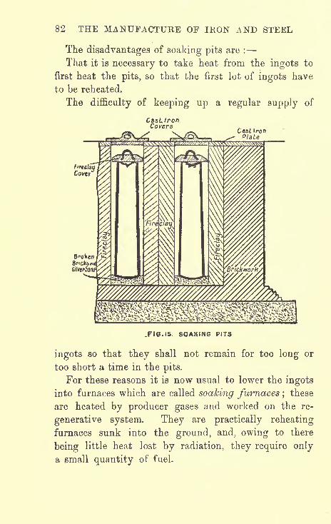
82 THE MANUFACTURE OF IRON AND STEEL
The disadvantages of soaking pits are :
That it is necessary to take heat from the ingots to
first heat the pits, so that the first lot of ingots have
to be reheated.
The difficulty of keeping up a regular supply of
CasLtronCovers
Cast IronPlate
.FIG. 15 SOAKING PITS
ingots so that they shall not remain for too long or
too short a time in the pits.
For these reasons it is now usual to lower the ingots
into furnaces which are called soaking furnaces ; these
are heated by producer gases and worked on the re-
generative system. They are practically reheating
furnaces sunk into the ground, and, owing to there
being little heat lost by radiation, they require only
a email quantity of fuel.

TREATMENT OF STEEL INGOTS 83
FLUID COMPRESSION
The soundness of an ingot may be improved by
subjecting the fluid steel in the mould to a very high
pressure. The pressure squeezes some of the occluded
gases from the fluid as water is squeezed from a sponge,and the remaining gases being compressed occupysmaller spaces within the mass of the metal. Thus
the particles of steel are forced into more intimate
contact with each other, and the grain is made finer
and more homogeneous. The numbers of the blowholes
may not be much reduced by compression, but it is
evident that their sizes must be reduced. For example,a pressure of 5 tons per square inch is equivalent to a
pressure of 761 atmospheres; this pressure would com-
press a bubble of gas into T^T of its natural volume,
or ^ of its diameter. It has been found that pressures
up to 2 tons per square inch have no beneficial effect
on the steel, so pressures of 5 to 10 tons per squareinch are applied. Such high pressures cannot be
applied to steel cast in ordinary cast-iron ingot moulds,
so special and expensive moulds have to be made.
The moulds are made of forged steel hoops, roughturned and bored, lined all round the inside circum-
ference with cast-iron bars placed vertically and close
together. The edges of the bars next to the hoopsare chamfered off; the radial grooves, cut in the sides
of the bars, connect with the spaces formed by the
chamfering so as to permit the escape of gases from
top to bottom of the mould. An inner lining of
ganister is plastered on to the inner faces of the bars.
Fig. 16 shows a sectional plan of a portion of the
G2
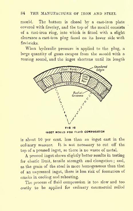
84 THE MANUFACTURE OF IRON AND STEEL
mould. The bottom is closed by a cast-iron plate
covered with fireclay, and the top of the mould consists
of a cast-iron ring, into which is fitted with a slight
clearance a cast-iron plug faced on its lower side with
firebricks.
When hydraulic pressure is applied to the plug, a
large quantity of gases escapes from the mould with a
roaring sound, and the ingot shortens until its length
Chamfered
Edges
FIG 16
INGOfT MOULD FOR FLUID COMPRESSION
is about 10 per cent, less than an ingot cast in the
ordinary manner. It is not necessary to cut off the
top of a pressed ingot, so there is no waste of metal.
A pressed ingot shows slightly better results in testing
for elastic limit, tensile strength and elongation ; and,
as the grain of the steel is more homogeneous than that
of an unpressed ingot, there is less risk of formation of
cracks in cooling and reheating.
The process of fluid compression is too slow and too
costly to be applied for ordinary commercial rolled

TREATMENT OF STEEL INGOTS 85
steel, and it is used only in the manufacture of such
special steel as is required for guns, crank and propellor
shafts, etc.
EFFECTS OF HAMMERING, ROLLING, AND
PRESSING STEEL
When steel is poured into a cold mould, the portion
next to the mould is immediately solidified and forms
a thin outer shell. As heat from the interior escapes
through this shell, steel is continually being solidified
and, so to speak,"frozen
"on to the outer shell.
As the whole mass of metal contracts, approximatelyin proportion to the decrease of temperature, the fluid
steel in the centre performs two functions. It con-
tinues to freeze on to the outer shell, and it also
endeavours to fill the void in the centre caused bycontraction.
The effect is that the steel in the interior of an ingothas a loose texture and it is defective.
To explain this in another way : The outer shell of
an ingot is immediately formed, and its dimensions^ are
not materially altered when the metal is cold. But as
there has been a considerable decrease of volume, the
ingot must have either a hollow centre or be of loose
texture.
The volume of steel when cold is about 6 per cent,
less than when fluid;so the amount of contraction of
an ingot of rectangular section, 15 inches x 14 inches,
is equivalent to a cavity of about 3J inches diameter in
its centre.
The greater the size of an ingot the coarser will be
the grain in the centre ; therefore the centre requires.

86 THE MANUFACTURE OF IRON AND STEEL
the most forging in order to force the particles of steel
into intimate contact with each other.
But, as force has to be applied from the outside, it is
difficult to properly forge the interior of an ingot. Apressure is more effective than a blow in transmittingforce from the outside to the centre.
If an ingot of mild steel could be removed from a
soaking pit or a soaking furnace at the exact time that
its centre is at a"welding heat
"that is, a temperature
most suitable for welding the particles of steel in the
centre might be welded together by a forging press,
and a steel with a fine grain would be produced.It is, however, always uncertain that the centre is at
a welding heat during the process of forging.
Ingots which have to be reheated before forging,
cannot be brought to a welding heat in their centres.
An ingot of high carbon steel which does not weld is
generally more defective in the centre than an ingot of
low carbon steel.
The blow of a steam hammer is too rapid to permit of
the pressure being transmitted from the surface to the
centre, where it is the most needed. The difference in
the effect of a blow and a squeeze in forging an ingot
is easily seen. When an ingot is hammered, the energyis absorbed in spreading the surface, and the interior
may remain quite unaffected. The effect of the surface
being extended more than the interior is to make the
end of a bar or an ingot of- the shape as shown by A,
and of section shown by B, fig. 17.
When an ingot is squeezed, as by a hydraulic forging
press, the outside, on account of long contact with cold
masses of metal, loses its heat more rapidly than the

TREATMENT OF STEEL INGOTS 87
centre, and flows less easily than the hotter centre
portion ; the centre is thus squeezed out and the end is
of the shape shown at C and section D.
When an ingot is rolled in a rolling mill, it is not
squeezed out in the same way as by a forging press,
B
JFIG. 17.
EFFECTS OF HAMMERING ROLLING AND PRESSING
because the surfaces of the rolls are moving in the same
direction in which the bar lengthens, and the rolls dragforward the outer surfaces in contact with them, so the
end of a rolled bar will be shaped as E. If the ingot is
rolled between plain rolls and not in grooves, which
prevent it from spreading laterally, the centre will be
squeezed so that the section will be of the same shapeasD.
CHAPTER XII
EFFECTS OF ADDING OTHER METALS TO STEEL
STEEL readily forms an alloy with most metals, and a
small quantity of added metal makes a great difference
in its properties.
Manganese. Some manganese is necessary in steel
to counteract a tendency to red shortness. It acts as a
deoxidiser. Mild steel ingots containing 0*2 per cent,
only of manganese are usually unsound. As the pro-
portion increases, the ingots become sounder ;but if the
proportion of manganese is over 1 per cent, it becomes
detrimental, as the power of elongation of the steel
then commences to be reduced. Steel with 2-| per cent,
to 7 per cent, of manganese is extremely brittle, but
with over 7 per cent, up to 18 per cent, the alloy
becomes practically a new metal which is called"manganese steel
"; this possesses great strength and
elasticity combined with hardness.
Aluminium is often added to steel, not with the
object of forming an alloy, but because of the action
which the metal has been found to have on molten steel.
Molten steel contains dissolved oxide of iron which
diminishes its fluidity and its strength. As the steel
cools, the oxide of iron, by the action of carbon, is to
some extent reduced, and CO gas is evolved. This88

EFFECTS OF ADDING OTHER METALS TO STEEL 89
gas causes an ebullition of the molten metal, and it is a
cause of blowholes. A small addition of aluminium
increases the fluidity of the metal and stops the evolu-
tion of gas. The reason for this is, that aluminium has
a greater chemical affinity for oxygen than iron has;
that is to say, it more readily combines with oxygenthan iron does.
The oxide of iron is reduced, and alumina, which
separates from the metal as slag, is formed. If too
much aluminium is added, it will not be all separated
and there will be weak spots in the steel.
Aluminium has the effect of preventing blowholes;
but as it stops the evolution of not only CO gas, but of
other occluded gases that is, hydrogen and nitrogen it
increases the coarseness of the grain of the cast ingot.
This coarseness, however, nearly disappears as the ingot
is being forged.
Nickel increases the tensile strength and ductility of
steel.
An alloy of nickel and steel is now largely used, and
it is a splendid material for forgings for the moving
parts of machinery.Nickel steel containing 30 per cent, of nickel can
easily be drawn out into wire, and as this large per-
centage of nickel renders the steel almost non-corrosive,
nickel steel is well adapted for ship's hawsers and
marine electric cables, which are subject to the corrosive
action of salt water.
Chromium. In small quantities, chromium slightly
raises the tensile strength of steel, but it also slightly
diminishes its ductility. When added in large quantities,
the steel becomes brittle.

90 THE MANUFACTURE OF IRON AND STEEL
Chromium is added to steel in conjunction with
nickel, for the inner "A" tubes of high-velocity guns;the proportions being :
Carbon, 0*4 per cent.; chromium, 1 per cent. ; nickel,
2 per cent.
Chromium makes steel hard, and nickel increases its
elasticity.
Vanadium. As an alloy, vanadium has, for quantity
used, the most powerful influence of all alloys on the
properties of steel. 0*2 per cent, of vanadium raises
the elastic limit and tensile strength of mild steel byabout 50 per cent. It is used in the manufacture of
the highest classes of tool steel, so-called"
self-hardeningsteel."
Steel under continual vibration or under variable
strains, such as the piston and connecting rods of an
engine, which are alternately under tension and com-
pression, becomes brittle or"fatigued"; the addition
of a small percentage of vanadium enables steel to
resist this deterioration.
Titanium. By adding to a bath of steel or cast iron
a ferro-carbon titanium containing about 1 5 per cent, of
titanium, the bath of metal can be almost cleansed from
dissolved or occluded gases, such as oxygen and nitrogen,
and from oxides of iron generally present in steel. In
the Bessemer process, when air is blown through the
molten iron, the titanium of the alloy combines with
oxygen as titanic dioxide (Ti02)and with nitrogen as
titanium nitride (TiN2).The oxide of iron is reduced
to iron by the titanium and the carbon of the alloy, the
titanium combining with its oxygen to form Ti02 . The
slag, always present in a metallic bath, rises and carries

EFFECTS OF ADDING OTHER METALS TO STEEL 91
with it the TiG2 and the TiN2 to the top of the bath.
It has been proved by experiments that Ti02 on enteringthe slag renders it more fluid and fusible.
One per cent, of titanium in steel renders it practically
rust-proof and so hard that it can be drilled with
difficulty.
Tungsten or wolfram alloyed with high carbon steel
renders it hard, and tools made of this alloy have
improved wearing properties. It also renders steel
retentive of magnetism, and is therefore used in the
manufacture of permanent magnets.
Tungsten was used in Germany in the composition of
the" A "
tubes the inner tubes of guns.

CHAPTER XIIT
MECHANICAL TESTING OF STEEL
THERE are two classes of tests to be applied :
1. Hot tests. The steel is heated to a welding heat
to find out if it is free from " red shortness," and if it
has good welding qualities.
2. Cold tests. To find out if it is free from "cold
shortness," and to ascertain the tensile strength, elas-
ticity, etc.
DEFINITIONS
Tensile strength (or tenacity) is the maximum stress
which a bar of a material can sustain, without breaking,
when a pulling force is applied gradually in the direc-
tion of its length.
It is usually expressed in tons per square inch of
cross section.
Elasticity is the quality which enables a material to
return to its original form or length on being released
from a force tending to alter its form or length. For
example, a metal bar may be stretched up to a certain
limit in a testing machine, and on being released it will
return to its original length ;a steel spring may be
bent by a force, but its elasticity will cause it to spring92
*

MECHANICAL TESTING OF STEEL 93
back and straighten itself when the force is released.
The act of springing back is called the resilience of
the spring.
Elastic limit (or limit of elasticity) is the maximumstress which a material can bear without being stretched
so much that it cannot return to its original length.
Permanent set. If a material is stretched beyondits elastic limit, it receives a permanent extension of
length which is called"permanent set." A material
in this condition is injured and is more liable to
"fatigue," which is brittleness caused by vibration or
variable stresses, than a material which has not been
stretched beyond its elastic limit.
Elongation is the amount of increase in length
which a metal can undergo when subjected to a stress
sufficient to break it up.
Contraction of area is the amount of reduction of
area which takes place at the point of fracture when a
metal bar is broken by a tensile stress.
Yield point is the point at which, when testing a
metal bar under a tensile stress just exceeding the
elastic limit, the bar suddenly and permanently
elongates by a considerable amount without any added
increase of stress.
Ductility is the quality which enables a metal to
hold together without being injured when subjected to
squeezing and stretching, as when rolled in a rolling
mill or being drawn out into wire.
Malleability is the quality which enables a metal to
endure hammering when being forged without being
cracked or broken.
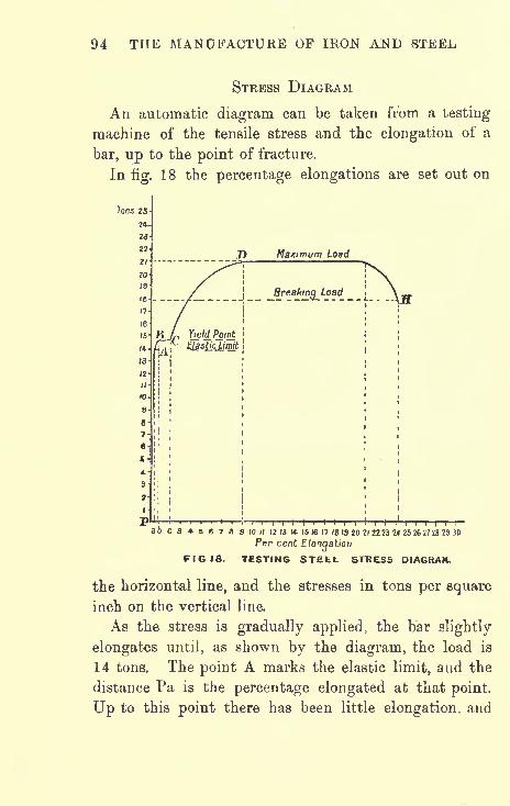
94 THE MANUFACTURE OF IRON AND vSTEEL
STRESS DIAGRAM
An automatic diagram can be taken from a testing
machine of the tensile stress and the elongation of a
bar, up to the point of fracture.
Infig.
18 the percentage elongations are set out on
Tons 25-

MECHANICAL TESTING OF STEEL 95
it has been uniform with the increase of load. Beyondthe point A the elongation is not uniform. Between
14 and 14^ tons, from A to B, there is a sudden
increase in the elongation, and at B the percentage
elongation is represented by Pb.
Pb is more than twice Pa, so the increase of elonga-
tion due to the extra load of ^-ton, from 14 to 14^- tons,
is more than double the total elongation due to the
load of 14 tons.
At the point B, suddenly, without any addition to
the load, there is a great increase in the elongation,
from B to C. B marks the "yield point." PC = about
5xPa.At the point C, the elongation ceases, but when a
further load, which should be applied gradually, is
added, the elongation increases up to the point D,
which marks the maximum load (in this case, 21 tons)
which the bar will bear. From the point D, the bar
goes on elongating, the elongation up to the point Dhaving reduced its sectional area (see fig. 20, page 93),
until it finally breaks at H.
The maximum breaking load at H is less than the
maximum tensile stress (18 against 21 tons), as, owingto the contraction of area at the point of fracture, a less
load is then required to break the bar.
In ordinary commercial testing the yield point is
generally taken as the elastic limit, as it is more easily
ascertained by the"drop of the beam
"of the testing
machine. The yield point is not the true elastic limit,
but it is very near it.
To find the elastic limit accurately, the points of a
pair of dividers should be held in the elongation

96 THE MANUFACTURE OF IRON AND STEEL
marks on the bar (elongation marks, see figs. 19 and
20, page 97). When it is seen that a slight elonga-tion takes place, take the load off and see if the marks
return to their original distance apart. If they do,
slightly increase the load and again release it; and so
on, until the load required to cause a very slight
permanent set is determined.
TEST-PIECES
The pieces of steel to be tested are of circular or
rectangular section; the circular section is preferable, as
the contraction in area after fracture can be more
exactly measured. For plates and angle bars, however,
it is necessary to cut strips of rectangular section.
Fig. 19 shows sketches of a piece cut from a plate,
before and after testing.
If the thickness is ^-inch, the width of the parallel
portion should be 1 inch ; this gives a cross sectional
area of \ square inch.
Before the piece is tested, marks are punched on it
8 inches apart ;after fracture the pieces are pressed
close together and the distance between the marks
measured. The distance in excess of 8 inches is the
amount of the elongation ;the percentage of elongation
can then be calculated. The bar has been elongated
from 8 inches to 9*6 inches that is, an elongation of
20 per cent.
Fig. 20 is a sketch of a test-piece of circular section,
before and after testing.
The centre punch marks are to be made within the
length which is of the smallest diameter. In this case,

MECHANICAL TESTING OF STEEL 97
the distance between the marks has been extended from
2 inches to 2|- inches an elongation of 25 per cent.
The length of the parallel portion under test must be
Before Jesting

98 THE MANUFACTURE OF IRON AND STEEL
To Calculate the Tensile Strength of a Test-piece
Divide the load at which it breaks by its original
sectional area.
Example. A test-piece, 07 5 -in. diameter, is broken
under a load of 15*5 tons, what is its tensile strength ?
75 x 75 x 7854 ='4417;15*5
.*. --- = 35 '1 = tensile strength in tons per sq. in.
To simplify the calculations for tensile strength, a test-
piece of circular section may be turned of such a
diameter that it will be necessary only to multiply the
load, which is read off from the beam of the testing
machine in Ibs., by 2 and divide by 1000 to obtain the
result in tons per square inch.
To Find this Diameter
Let x = sectional area in sq. ins.
and y = total load in Ibs.;
.'. ^ = tensile strength in Ibs. per sq. in.x
and --- = tensile strength in tons per sq. in.xx 2240
It is required that
xx 2240 1000
Then
x =- = "2232 sq. in. = sectional area of test-piece.4480
Let d = required diameter of test-piece,
then d2 x 7854 = '2232;
.'. d= '533 in.

MECHANICAL TESTING OF STEEL 99
Now, with a test-piece of -533-inch diameter, if the
breaking load is 17,420 Ibs., the tensile strength is
34 '84 tons per square inch.
Micrometer. For accuracy the diameter should be
measured with an instrument called a " screw micro-
meter," by means of which the diameter can be
ascertained to within yoVo ^ an incn >
To Find the Percentage Elongation
Example. Original distance between marks
on test-piece= 8 ins.
Distance between marks after
breaking test-piece= 9 *6 ins.
Difference = 1 *6 in.
,. 1-6x100.'. .Percentage elongation
= = 20.8
To Find the Percentage Contraction of Area
of a Test-piece.
Example. Diameter of piece before testing= '533 in.
Diameter of piece when broken = '34 in.
533 x -533 x 7854 = '2232 sq. in.
34 x '34 x 7854 = '0908 sq. in.
Difference = '1324 sq. in.
'1324x100 rn r ,= 5 9 '3 = percentage contraction of area.
TEST FOR WELDING AND HOT WORKING
Take two pieces of steel about 1 inch square and weld
them together as shown at A B infig. 21. Punch a

100 THE MANUFACTURE OF IRON AND STEEL
f-inch hole at C, and while still red-hot, expand the hole
with tapered drifts until it is about 2^- inches diameter.
The steel should show no sign of opening at the weld,
and the edges of the expanded portion should be smooth
and without cracks.
FIG Z\ TEST FOR WELDING
COLD BEND TESTS FOR MILD STEEL PLATES
A strip, 1^- inch wide, is cut lengthways or crosswise
from a plate, heated to a cherry-red colour, and cooled
in water at 82 F.
When cold, the strip is to be bent over a round bar,
the diameter of which is three times the thickness of
the strip, without showing any cracks.
CHAPTER XIII
HEAT TREATMENT OF STEEL
WHEN steel containing 0*25 per cent, or more of
carbon is heated to redness and suddenly cooled, it
becomes hard.
The influence which heating to various temperatureshas upon steel may be shown by the following
experiment :
Take a bar of tool steel about 1 foot long and f -inch
diameter and cut notches with a chisel at intervals of
1 inch throughout its length. Heat one end of the bar
in such a manner that it will be at a welding heat at that
end, and that there shall be diminishing degrees of red-
ness along the bar, until at the other end there is on
appearance of redness.
Now quench the bar in cold water, break off pieces at
each notch and compare the fractures. The piece which
has been heated to a welding heat will have a coarse
grain and will be very brittle. The grain becomes
finer with each succeeding piece until the fracture is as
that of porcelain ;the fractures of the two or three
pieces which have been heated to lower temperatureswill show a slightly coarser grain.
The part which has the finest grain is the strongest101

102 THE MANUFACTURE OF IRON AND STEEL
part of the steel bar, so the object of heat treatment is
to obtain the finest possible grain.If a piece of steel is heated to a welding heat and
allowed to cool naturally, it will have a coarse grain andwill be brittle ; but if the same steel is well hammeredor pressed in a forging press when at a welding heat, it
will have a fine grain and will be ductile.
HARDENING
There are conditions depending on the temperatureof carbon in steel which are called
" cement carbon"
and " carbon in the hardening state." The carbon
passes from the cement to the hardening state by an
increase of temperature, and from the hardening state to
the cement by a decrease of temperature.
Brinnel, in his experiments with steel containing 0'5
per cent, carbon, found that on heating there was a
particular temperature at which there was a retardation
in the rate of heating, and, at this temperature, which
he denoted by the letter W, the carbon changed from
the cement to the hardening state.
Also, on cooling steel which had been heated above W,there was a particular temperature at which there was a
retardation in the rate ofcooling, and, at this temperature,
which is denoted by the letter V, the carbon changedback from the hardening state to the 'cement. The tem-
perature V is about 30 C. less than the temperature W.
The temperature W is known as the critical temperature.
At the temperature W, the steel, in passing from the
cement to the hardening state, becomes of the finest
possible grain that can be obtained with that particular

HEAT TREATMENT OF STEEL 103
steel. It is then in the best condition for hardening,and is hardened by quenching in cold water. If heated
above W the grain again becomes coarse, and if
quenched at this higher temperature the steel will be
brittle.
When hardened at the temperature W, the steel has
its maximum hardness combined with its maximumtensile strength. The approximate critical temperaturesof steels with various percentages of carbon are :
Carbon '1 percent, 890 C.;Carbon '45 per cent., 800 C.;
Carbon 7 per cent., 750 C.;Carbon '95 per cent., 700 C.
CRYSTALLINE STRUCTURE
If the fracture of a steel bar be examined under a
microscope, it will be seen that the metal is built up of
minute crystals. The physical properties of steel vary
according to the sizes of the crystals and the relative
cohesion between them. The crystals are reduced in
size by forging or by rolling.
FORGING TEMPERATURE
The temperature at which steel is forged and the rate
of cooling which follows are considerations of the highest
importance. If forged at too high a temperature, the
steel will have a coarse crystalline structure causing low
elongation and low ratio of yield to breaking load.
Theoretically, the forging temperature should not exceed
the critical temperature by more than about 50 C.
This, however, can hardly be carried out in practice,
and good results will be obtained by a forging tern-

104 THE MANUFACTURE OF IRON AND STEEL
perature, for example, which does not exceed 1150 C.
for steel with *45 per cent, carbon. That is to say, the
steel may be heated to a bright yellow, but not to a
white heat.
NORMALISING AND ANNEALING
The main difference in the above-named heat treat-
ments is that steel is" Normalised
"by reheating and
rapid cooling in order to remove internal stresses and
restore it to a " Normal" unstressed condition, and steel
is" Annealed
"by reheating and slow cooling in order
to soften the metal preparatory to machining.In both cases, for example, '35-*55 per cent, carbon
steel is reheated to about 850 C., which is slightly above
its critical temperature.
Normalising. This term was originally applied to
methods of regulating and equalising the cooling of steel
articles of irregular section; tyres, for example, the
flanges or thin parts of which would ordinarily cool
more rapidly than the thick parts and thus cause severe
internal stresses to be set up. The cooling of the
massive part is hastened and the cooling of the thin
part is retarded, so that the whole article is cooled at a
uniform rate.
Normalising is now more generally understood to
mean that the material is reheated and then cooled at
a rate sufficiently rapid to appreciably raise the yield
point, but not so quickly as to cause brittleness or
excessive hardness.
Steel is slowly heated to and allowed to soak at the
required temperature ; it is then removed from the
furnace and allowed to cool in the open air, sheltered

HEAT TREATMENT OF STEEL 105
from rain or snow. The articles under treatment should
be kept separate from each other, so that they may be
uniformly cooled by the air circulating freely around
them.
Steel which is not heated to just above its critical
temperature is not normalised. If this temperature is
not reached, its state remains unchanged ; and if the
temperature is greatly exceeded, it will become coarse in
grain, brittle and low in yield.
If steel bars have been overheated and rolled at too
high a temperature, the tensile test will show low yieldand elongation. They may usually be rectified by
normalising. If rolled at too low a temperature, an
excessively high breaking load and low elongation should
be rectified by annealing. If only slightly in excess of
the requirements for these tests, rectification is better
effected by normalising.
Annealing. When the steel has been reheated it
should be allowed to cool slowly, either in the furnace
or by keeping a number of pieces of the material close
together during cooling. If the steel is heated for too
long a period or if the rate of cooling is too slow, it
is liable to be weakened. Prolonged heating induces
the growth of large crystals ; and the effect of veryslow cooling is a segregation of ferrite and pearlite,
which causes the steel to be less homogeneous. Thebest mode of treatment can only be ascertained byexperience.
Generally speaking, the process of annealing slightlyraises the yield point and considerably increases the
elongation.

106 THE MANUFACTURE OF IRON AND STEEL
TEMPERING
The hardening given to steel by quenching in water,
at temperature W, is not suitable for all purposes, so
the brittleness produced by hardening is reduced by
"tempering"; the "temper" being made to suit the
particular purpose for which the steel is required. This
is effected by heating the steel to a temperature verymuch below that required for hardening ;
the steel is
then either quenched or allowed to cool naturally.
Tempering reduces the brittleness and hardness, and
increases the ductility and elastic limit;
the tensile
strength is not materially altered.
PRACTICAL TEMPERING OF STEEL
When a steel is stated to be of high, low, or medium"temper," it does not mean that it has been tempered
to a high, low, or medium degree of hardness;
it
means that it is a high, low, or medium carbon steel
capable of taking a high, low, or medium degree of
hardness.
Thus, 1*5 per cent, carbon steel would be called"high
temper" steel, and 0'3 per cent, carbon would be called" low temper."
In tempering, the steel should be first hardened by
heating to a dull red heat and quenching in water. The
surface is then filed bright and gradually heated by
laying it on a piece of red-hot iron, or in any other
convenient way. The surface then becomes oxidised
and changes in colour as the temperature is raised :
the colours in succession are :

HEAT TREATMENT OF STEEL 107
Indicating a temperaturesuitable for tempering :
Dark blue.
Light blue .... Springs, saws.
Purple . Axes, chisels for cut-
ting iron or steel.
Light brown to dark brown . Taps, drills.
Light straw to straw . . Lathe tools, files.
When the colour indicates that the right temperaturehas been reached, the steel is either quenched or allowed
to cool in the air. If the whole of the metal is required
to be of the same degree of hardness, it is air cooled ;
but in the case of cutting tools, only the cutting edge
requires tempering. A tool is heated to a dull red at
the cutting end;this extreme end only is quenched and
filed bright. The end then becomes reheated by heat
conducted from the rest of the tool, and when the
cutting edge shows the required colour, the whole tool
must be quenched.The degree of hardness given to the steel will depend
not only on the temperature to which it is heated, but
on the rapidity with which it is cooled by quenching.
Quenching in mercury, cold brine, or cold water, has
a greater hardening effect than quenching in hot water,
oil, or molten lead.
Quenching in oil. The effect of quenching in oil is
generally to increase the elasticity of steel. Springsand saws, which should be elastic, but which are not
required to be very hard, are quenched in oil.
Quenching in lead. This has practically no effect on
mild steel, but it slightly improves the tensile strength,

108 THE MANUFACTURE OF IRON AND STEEL
elastic limit, elongation, and contraction of area of veryhard steel.
PYROMETERS
For exact determination of the temperatures of re-
heating furnaces and of steel when reheated for forging
or heat treatment, one or other of the following instru-
ments are used :
Electrical Resistance Pyrometer. This consists of
a coil of platinum or other metal wire inserted in and
protected by a tube of porcelain or fused quartz, the
closed end of which is exposed to the full heat of the
furnace.
The electrical resistivity of pure metals increases
regularly with increases of temperature and by connect-
ing the ends of the coil with a suitable instrument
accurate temperature measurements up to 1000 C. can
be made.
Thermo-Electric Pyrometer. Two wires of different
metals are fused or twisted together at one end, which,
protected by a fused quartz tube, is placed in the
furnace. The other ends of the wires are connected
to "a galvanometer which measures the small electric
current produced by the heating of the wires.
This instrument gives less accurate temperaturemeasurements than the resistance pyrometer, but it can
be used for temperatures up to 1700 C.
Radiation Pyrometer. This instrument is placed
outside the furnace and radiations of heat from the
interior or from a billet in the furnace are concentrated
by means of a concave mirror on to a"Thermo-Couple
"
contained in a tube. The current of electricity gene-

HEAT TREATMENT OF STEEL 109
rated by the heating of the thermo-couple is then
measured.
Optical or Photometric Pyrometer. This instrument,
also, is used outside the furnace and its action is based
on a comparison of the colour of the light emitted bya heated substance within the furnace with that of a
standard incandescent lamp.
A diaphragm in the instrument is rotated until the
light received from the hot metal is adjusted to equal
intensity with that of a beam of similar light from the
lamp.This form of pyrometer is the most convenient for
ascertaining the temperature of a billet as it leaves the
furnace and again after forging. It can be manipulatedin a few seconds and the temperature is read from a
scale on the instrument.

INDEX.Acid Bessemer process, 58.
open-hearth process, 39.-
steel, 31, 36.
Acids, 36.
Air blast in blast furnace, 11.
Bessemer converter, 59.
Alloy, 1.
Alumina, 36, 89.
Aluminium, 2, 34, 88.
Annealing steel, 104, 105.
Atomic weights, 2.
Basic Bessemer ore, 19.
bricks, 51.
lining, 51, 66.
materials, 50.
open-hearth process, 50.
steel, 37.
Bessemer converter, 58.
lining, 59, 66.
process, 35, 58, 66.
Best tap, 24, 53.
Blast furnace, 9.
gases, 20.
Blowing engines, 14.
Calcination, advantages of, 7.
Calcining kiln, 7.
Carbon, chemical colour test for, 47.
dioxide, 4.
monoxide, 3.
percentages of, in steel, 27.
Carbonic acid gas, 4.
Cementation boxes, 28.
furnace, 28.
process of, 28.
Chromium, 86.
Cleveland ironstone, 6, 19.
Coke, 15.
Cold short, 4, 27.
Contraction of area, 93, 97.
Converter, Bessemer, 58.
side- or surface-blown, 62.
Critical temperature, 102.
Crystalline structure, 103.
Darby recarburising process, 57.
Dolomite, 51, 66.
110
Ductility, 93.
Elastic limit, 93.
Elasticity, 92.
Electric furnace, 76.
Elongation, 98, 99.
Fatigue of metals, 57, 90, 93.
Ferric ore, 6.
oxide, 3.
Ferro-manganese, 33, 35, 48.
analysis of, 46.
Ferrous ore, 6.
oxide, 3.
Ferrous-ferric ore, 6.
Fettling, 23, 24.
materials, 24.
Fluid compression, 83.
Flux, 15.
Furnace, blast, 11.
cementation, 28.
electric, 76.
for crucible steel, 31.
lining, acid open-hearth, 43.
basic open-hearth, 51.
puddling, 22.
reheating, 81.
reverberatory, 24.
Siemens open-hearth, 39.
soaking, 82.
tapping, 9.
Gangue of ore, 6.
Ganister, 43.
Gas producer, 38.
Gases, blast-furnace, 17.
in occlusion, 79.
occluded, 32, 79.
Grain of metal, 20.
Hardening steel, 102.
Heat, Bessemer blow, 64, 70.
Hematite ore, 6, 25, 45.
pig iron, 19, 46.
Hot-blast stove, 12.
Ingots, fluid compression of, 83.
gases in, 79.
stoppering, 80.

INDEX 111
Ingots, treatment of, 79.
Iron, cast, 17.
ores, 6.
oxides, 3.-pig, 17, 19.
analysis of, 19, 44, 73.
wrought, 22, 34.
Lead tempering, 107.
Limestone, 15, 69.
analysis of, 51.
Limit of elasticity, 93.
Lining of Bessemer converter, 59, 6
of furnace, acid open-hearth, 43.
basic open-hearth, 50.
Magnesite, 51.
Magnetic oxide, 3.
Magnetite ore, 6.
Malleability, 93.
Manganese, 2, 8, 28, 88.
steel, 88.
Micrometer, 99.
Mixer, 60.
Neutral course, 52.
Nickel, 2, 86.
Normalising, 104.
Occluded gases, 32, 79.
Occlusion, gases in, 79.
Oil combustion converter, 76.
tempering, 107.
Open-hearth furnace, 39.
Ore, calcination of, 7,
Cleveland, 6.
ferric, 6.
ferrous, 6.
ferrous-ferric, 6.
hematite, 6, 45.
magnetite, 6.
non-fluxing, 1 6.
reduction of, 16.
self-fluxing, 16.
Oxide, ferric, 3.
ferrous, 3.
magnetic, 3.
Permanent set, 93.
Phosphorus, 4.
Pig iron, 17, 19.
analysis of, 19, 44, 73.
Pottery mine, 25, 53.
Producer gas, 38.
Puddling furnace, 22.
Purple ore, 25.
Pyrometer, 108.
Red short, 4, 27.
Regenerator, 12, 39.
Resilience, 93.
Reverberatory furnace, 24.
Sand, white or silver, 43.
Segregation, 80.
Short, cold, 4, 27.-red, 4, 27.
Siemens acid process, 36, 38.
basic process, 50.
Silica, 4.
Silicon, 4.
Slag, acid Bessemer, 65.
acid Siemens, 49.
basic Bessemer, 72.
basic Siemens, 55.
blastfurnace, 17.
wool, 19.
Smelting, 9.
Soaking furnace, 82.
pits, 81.
Spiegelaisen, 35, 48.
analysis of, 46.
Steel, acid, 36.
annealing, 104, 105.
basic, 37.
blister, 28.
crucible, 30.
double shear, 30.
hardening, 102.
lead tempering, 107.
mild, analysis of, 34.
oil tempering, 107.
percentage of carbon in, 27.
single shear, 30.
tempering, 106.
Stove, hot-blast, 12.
Temperature (critical), 102.
Tempering, 106.
in lead, 107.
in oil, 107.
Tenacity, 92.
Tensile strength, 92, 98.
Test- pieces, 96.
Testing of steel, 92.
Tests, cold, 39, 92, 100.
hot, 92, 99.
welding, 99.
Titanium, 2, 90.
Tungsten, 2, 91.
Tuyeres, 11, 59, 67.
Vanadium, 2, 90.
Wheelswarf, 28.
Wolfram, 2, 91.
Wrought iron, analysis of, 22, 35.
Yield point, 93.

(PR. 1602.)
PRINTED IN GREAT BRITAIN BV
NEILL AND CO., LTD.,
EDINBURGH.


FOURTEEN DAY USERETURN TO DESK FROM WHICH BORROWED
LOAN DEPT.This book is due on the last date stamped below, or
on the date to which renewed.
Renewed books are subject to immediate recall.
:
|Jun'56HJ

UNIVERSITY OF CALIFORNIA LIBRARY


