
Journal of Computers Vol. 28, No. 1, 2017, pp. 247-260
doi:10.3966/199115592017022801019
247
The Tracking Control Design of Adaptive Fuzzy CMAC
for an Omni-Directional Mobile Robot
Ter-Feng Wu1*, Hsu-Chih Huang1, Pu-Sheng Tsai2,
Nien-Tsu Hu3, and Zhi-Qiang Yang1
1 Department of Electrical Engineering, National Ilan University
Yilan 260, Taiwan, ROC
{tfwu, hchuang}@niu.edu.tw; [email protected]
2 Department of Electronic Engineering, China University of Science and Technology
Taipei 115, Taiwan, ROC
3 Chemical Systems Research Division, National Chung-Shan Institute of Science and Technology
Taoyuan 325, Taiwan, ROC
Received 18 June 2015; Revised 19 February 2016; Accepted 27 December 2016
Abstract. This work presents an adaptive fuzzy cerebellar model articulation controller
(AFCMAC) for solving the tracking control problem for an omni-directional mobile robot. First,
fuzzy logic and CMAC are combined, coupled with a triangular basis function that is embedded
in the hypercube receptive-field space to yield non-constant differentiable basis functions, which
simplify the complex structure and reduce the number of input space dimensions of CMAC.
Both adaptive and control laws are developed to tune all of the control parameters online, ac-
commodating uncertainty in tracking control for an omni-directional mobile robot. Hardware
agencies and drive circuits are developed. This proposed AFCMAC is implemented in a high-
performance field-programmable gate array (FPGA) chip using a hardware/software co-design
method and the Qsys design concept with a reusable user IP (Intellectual Property) core library.
An omni-directional mobile robot is thus produced. Finally, the trajectory tracking controllabil-
ity of the robot along both straight and elliptical paths is simulated to evaluate the effectiveness
of the proposed AFCMAC and establish the feasibility and performance of uncertain tracking
control.
Keywords: adaptive control, cerebellar model articulation controller (CMAC), fuzzy set, omni-
directional mobile robot
1 Introduction
In recent years, much research has been performed into control problems associated with nonlinear con-
trol systems [1]. Systems theory and the traditional feedback control theory have led to various control
schemes that depend on exact mathematical system dynamical models. However, most of these ap-
proaches involve many uncertainties when implemented in practice, which may be associated with in-
completeness of the model or several unresolvable disturbances. A well-developed control system must
exhibit high dynamic performance and robustness even when implemented under complexity and uncer-
tainty [2-4].
Intelligent control theory is utilized in dynamic models to eliminate uncertainties that are caused by
disturbances. Systems that are based on the theory include neural networks (NNs) [5-6] fuzzy control of
* Corresponding Author

The Tracking Control Design of Adaptive Fuzzy CMAC for an Omni-Directional Mobile Robot
248
complex processes with reference to human experience [7-8] and robust control, which is resistant to
disturbances [9]. Drawing on Marr’s model, Albus established a cerebellar model known as the “cere-
bella model articulation controller” (CMAC) [10]. A neural network that models the structure and func-
tion of the human cerebellum, the CMAC exhibits motor behaviors without using any complex algorithm;
it is a table look-up mechanism that comprises a series of function mapping.
The cerebellar model has advantages over conventional NNs; it is composed of simple theoretical
structures, requires easy computation, exhibits fast learning and favorable local generalization, approxi-
mates multiple non-linear systems, and can be easily implemented in both hardware and software. If the
CMAC is merged into a fuzzy set, its complex structure can be simplified and its input space dimensions
can be reduced. Adaptive and control laws can be developed to tune all of the control gains online, ac-
commodating uncertainty in an omni-directional robot without any learning phase [11].
Over the last few years, the trajectory tracking control of four-wheeled omni-directional mobile robots
[12] has become the focus of much academic interest. However, the control structure of the CMAC can-
not be utilized to solve the trajectory tracking control problem of such a robot. To enable highly precise
trajectory tracking control of the four-wheeled omni-directional mobile robot, this work demonstrates a
modified CMAC system as a response to improve upon the limited mathematical descriptions in the con-
ventional one, and proposes an AFCMAC that is equipped with an embedded switch robust controller to
accommodate uncertainties and unpredictable disturbances of the multi-dimensional nonlinear system.
Based on the previous work of [13], a Lyapunov stability analysis is carried out so that all of the closed-
loop signals are bounded and the tracking errors can converge asymptotically to zero. This proposed
methodology is instrumental in the design of an intelligent motion controller of the omni-directional mo-
bile robot.
2 Structure of Controller
2.1 Omni-Directional Mobile Robot
Fig. 1 shows the geometric structure of the omni-directional mobile robot. Owing to the structural sym-
metry of the vehicle, its center of geometry is also the center of mass. The kinematic model of this robot
follows, where θ denotes the orientation of the vehicle, which is positive in the counterclockwise direc-
tion [12-13].
δ
θ
1T
2T
3T
4T
Xω
Yω
mx
my
Fig. 1. Structure of omni-directional mobile robot
According to the previous work [13], the kinematic model of an omni-directional mobile robot can be
described as follows:
1 1
2 2
3 3
4 4
( ) ( )( )
( ) ( )( ) ( ( )) ( )
( ) ( )( )
( ) ( )
t r tx t
t r tt P t y t
t r tt
t r t
υ ω
υ ωυ θ
υ ωθ
υ ω
⎡ ⎤ ⎡ ⎤⎡ ⎤⎢ ⎥ ⎢ ⎥⎢ ⎥⎢ ⎥ ⎢ ⎥= = = ⎢ ⎥⎢ ⎥ ⎢ ⎥⎢ ⎥⎢ ⎥ ⎢ ⎥ ⎣ ⎦
⎣ ⎦ ⎣ ⎦
�
�
�
(1)

Journal of Computers Vol. 28, No. 1, 2017
249
sin( ) cos( )
cos( ) sin( )( ( ))
sin( ) cos( )
cos( ) sin( )
L
LP t
L
L
δ θ δ θ
δ θ δ θθ
δ θ δ θ
δ θ δ θ
− + +⎡ ⎤⎢ ⎥− + − +⎢ ⎥=⎢ ⎥+ − +⎢ ⎥
+ +⎣ ⎦
(2)
where ( ), 1,2,3,4it iω = is the angular velocity of each wheel; r denotes the radius of each wheel, and L
represents the distance from the center of the platform to the center of each wheel.. Notably, although the
matrix ( ( ))P tθ is nonsingular for all θ , its inverse matrix can be found using # ( ( )) ( ( ))P t P t Iθ θ = , and
expressed as
#
sin( ) cos( ) sin( ) cos( )
2 2 2 2
cos( ) sin( ) cos( ) sin( )( ( ))
2 2 2 2
1 1 1 1
4 4 4 4
P t
L L L L
δ θ δ θ δ θ δ θ
δ θ δ θ δ θ δ θθ
− + − + + +⎡ ⎤⎢ ⎥⎢ ⎥
+ − + − + +⎢ ⎥=⎢ ⎥⎢ ⎥⎢ ⎥⎢ ⎥⎣ ⎦
(3)
2.2 CMAC Design
The physical system to be controlled is assumed to have only one control input, and all of the state vari-
ables are assumed to be available. Accordingly, a single-output CMAC is designed, with the structure
that is shown in Fig. 2, and an output that is given by
( )CMACz F= s (4)
where : LF →R R is a nonlinear function of the CMAC input variable
1[ , , ]
T L
Ls s S= ∈ ⊂s R� . To
mimic the operation of the human cerebellum, the inputs (sensors) are related to the output (response) by
an association mechanism with association memory space A. Any element in A comprises 0s and 1s, as
determined by the pattern of the inputs. Vector w is the CMAC weight vector. Mathematically, the rela-
tion (1) can be represented by a pair of mappings,
: ; ( ) ( )G S A G A→ = ∈s s a s� (5)
: ; ( ).P A P→R a a� (6)
In particular, the function P can be chosen to generate output CMACz , as follows.
( )CMAC
Tz P= =a a w (7)
where M∈a R is the relevance vector; [ ]1
M b
b
×
≡ ∈W w w R� denotes the CMAC weight matrix, and
, 1, ,M
ii b∈ =w R �
Fig. 3 shows a possible partition of the input variables of the CMAC, in which both s1 and s2 are divided
into seven quantified elements, so that 49 inputs states, with , 3, 2, 1,0,1,2,3m n = − − − , are formed yield-
ing 49 inputs states, with , 3, 2, 1,0,1,2,3m n = − − − . These elements are further grouped into three blocks,
(A, B, C) and (a, b, c), respectively for s1 and s2 in the first layer. Their combinations
, , , , , , , ,Aa Ab Ac Ba Bb Bc Ca Cb Cc are represent the hypercubes. Shifting the first layer step-by-step on
the blocks yields the second and third layers, so that an association vectora is formed as [T≡a Aa Ab Ac
Ba Bb Bc Ca Cb Cc Dd De Df Ed Ee Ef Fd Fe Ff Gg Gh Gi Hg Hh Hi Ig Ih Ii ].

The Tracking Control Design of Adaptive Fuzzy CMAC for an Omni-Directional Mobile Robot
250
Input
space, S
Receptive-field
space , T
Weight
memory
space, W Output
space, Y: →G S A
Aa
Ab
(1,1) Σ1
L
s
s
�
for L=2
case
for M=27
case
w1
w2
w3
w4
w5
w6
w7
w8
w26
w27
1 mw w�
:m
→P A R
Association
memory space , A
(-2,2)
Σ
Σ
Σ
�
Output
YCMAC1
YCMACm
..
.
..
.
Ac
Ba
Bb
Ii
Ih
..
.
..
.
Bc
Ca
Cb
Fig. 2. Architecture of CMAC
A B
D E F
G H I
1s
2s
C
( 2 ,1 )( 1 ,1 )( 0 ,1 ) ( 3 ,1 )( - 1 ,1 )( - 2 ,1 )( - 3 ,1 )
( 2 ,0 )( 1 ,0 )( 0 ,0 ) ( 3 ,0 )( - 1 ,0 )( - 2 ,0 )( - 3 ,0 )
( 2 , - 1 )( 1 , - 1 )( 0 , - 1 ) ( 3 , - 1 )( - 1 , - 1 )( - 2 , - 1 )( - 3 , - 1 )
( 2 ,2 )( 1 ,2 )( 0 ,2 ) ( 3 ,2 )( - 1 ,2 )( - 2 ,2 )( - 3 ,2 )
( 2 ,3 )( 1 ,3 )( 0 ,3 ) ( 3 ,3 )( - 1 ,3 )( - 2 ,3 )( - 3 ,3 )
( 2 , - 2 )( 1 , - 2 )( 0 , - 2 ) ( 3 , - 2 )( - 1 , - 2 )( - 2 , - 2 )( - 3 , - 2 )
( 2 , - 3 )( 1 , - 3 )( 0 , - 3 ) ( 3 , - 3 )( - 1 , - 3 )( - 2 , - 3 )( - 3 , - 3 )
- 2 .5
- 1 .5
- 0 .5
0 .5
1 .5
2 .5
3 .5
- 3 .5
0
- 2 .5 - 1 .5 - 0 .5 0 .5 1 .5 2 .5 3 .50
Fig. 3. Partition of two-dimensional CMAC memory unit
For example, if 1 2
[ , ] [0.6,0.7]T T
s s S= ∈ , then the corresponding input state is (1, 1) and the associated
hypercubes are Ba, Fe, and Hh, yielding [000100000000000010000010000]T
=a , which in turn yields
the following indexing matrix.
1
2
16
000100000000000010000010000a
000000001000001000000001000aa
000100010001000000000000000a
T
T
T
⎡ ⎤ ⎡ ⎤⎢ ⎥ ⎢ ⎥⎢ ⎥ ⎢ ⎥= =⎢ ⎥ ⎢ ⎥⎢ ⎥ ⎢ ⎥⎢ ⎥ ⎣ ⎦⎣ ⎦
�� (8)
Sequential triangular states are embedded into each block variable, as presented in Fig. 4. The relevant
equation is expressed as follows.

Journal of Computers Vol. 28, No. 1, 2017
251
Fig. 4. Triangular states
( )
1
x aa x b
b a
c xtri x b x c
c b
x b
−⎧< <⎪ −
⎪−⎪
= < <⎨−⎪
=⎪⎪⎩
,
,
,
(9)
where a is the lowest valueof any of the block variables; b is the central point of the embedded triangu-
lar function blocks; c is the largest value among the block variables, and x represents input variables
whose values influence the output of the regions that are covered by functions.
2.3 FCMAC Design
Fig. 5 presents a concept map of fuzzy sets that are integrated with the CMAC that presents a possible
partition of the input variables of the CMAC. For a two-input problem, a fuzzy system with N fuzzy rules
may be designed, each of which has the form,
( )
1 1 2 2: is and is ,i i i
s F s FR IF( )
is i T
f izTHEN a w (10)
where 1,2, ,i N= � , and the THEN-part is extracted from the CMAC. Given the membership function of
fuzzy set i
kF , 1,2,k = denoted as i
kF
µ , the following defuzzification process is used to compute the out-
putFCMACz .
1s
PN
1 11
( )F
sµ
2s
N
P
1
22
( )F
sµ
Z
Z
0
0
(2 ,1 )(1 ,1 )(0 ,1 ) (3 ,1 )(-1 ,1 )(-2 ,1 )(-3 ,1 )
(2 ,0 )(1 ,0 )(0 ,0 ) (3 ,0 )(-1 ,0 )(-2 ,0 )(-3 ,0 )
(2 ,-1 )(1 ,-1 )(0 ,-1 ) (3 ,-1 )(-1 ,-1 )(-2 ,-1 )(-3 ,-1 )
(2 ,2 )(1 ,2 )(0 ,2 ) (3 ,2 )(-1 ,2 )(-2 ,2 )(-3 ,2 )
(2 ,3 )(1 ,3 )(0 ,3 ) (3 ,3 )(-1 ,3 )(-2 ,3 )(-3 ,3 )
(2 ,-2 )(1 ,-2 )(0 ,-2 ) (3 ,-2 )(-1 ,-2 )(-2 ,-2 )(-3 ,-2 )
(2 ,-3 )(1 ,-3 )(0 ,-3 ) (3 ,-3 )(-1 ,-3 )(-2 ,-3 )(-3 ,-3 )
-3 .5 -2 .5 -1 .5 -0 .5 0 .5 1 .5 2 .5 3 .5
-2 .5
-1 .5
-0 .5
0 .5
1 .5
2 .5
3 .5-3 .5 -2 .5 -1 .5 -0 .5 0 .5 1 .5 2 .5 3 .50
0
-2 .5
-1 .5
-0 .5
0 .5
1 .5
2 .5
3 .5
-3 .5
Fig. 5. Conceptual map of (fuzzy sets integrated integration of fuzzy sets with CMAC

The Tracking Control Design of Adaptive Fuzzy CMAC for an Omni-Directional Mobile Robot
252
1 1 2 2
1 2
FCMAC
T T T
N N
N
v v v
z
v v v
+ + +
=
+ + +
a w a w a w�
�
1
1
NT
i ii
N
ii
v
v
=
=
∑
=
∑
a w
(11)
where 2
1
( ).i
ki kF
k
v sµ=
= ∏ The preceding equation may be re-written compactly as
FCMAC
Tz = h Aw (12)
where
[ ]1 2
1
,
Ti
N i N
ii
vh h h h
v=
= =
∑
h � [ ]1 2, , ,
T
N=A a a a� (13)
and
1
2
T
T
T
N
⎡ ⎤⎢ ⎥⎢ ⎥=⎢ ⎥⎢ ⎥⎢ ⎥⎣ ⎦
a
aA
a
� (14)
In Equation (12), matrix A (determined by the CMAC) and vector h (determined by fuzzy rules) are
typically fixed, but the weight vector w is adjustable herein.
In solving the two-input problem, a set of membership functions can be selected, as displayed in Fig. 5,
in which P (positive), Z (zero), and N (negative) fuzzy sets are imposed on each variable. Therefore, nine
fuzzy sets with nine association vectors,1a ,
2a ,
3a ,
4a ,
5a ,
6a ,
7a ,
8a , and
9a , are attached to (P, P),
(P, Z), (P, N), (Z, P), (Z, Z), (Z, N), (N, P), (N, Z), and (N, N), respectively. The CMAC includes 49 asso-
ciation vectors in the CMAC, but the FCMAC has only nine. To determine i
a in the FCMAC, the logical
operation ‘OR’ is performed on all possible association vectors in the same group in the CMAC, yielding
association vector,a :
1
2
3
4
5
6
7
8
9
000100100000000110000110110
000010010000000010000010010
000011011000000001000011011
000100000000110000000110000
000010000000010000000010000
00001
T
T
T
T
T
T
T
T
T
⎡ ⎤⎢ ⎥⎢ ⎥⎢ ⎥⎢ ⎥⎢ ⎥⎢ ⎥
= =⎢ ⎥⎢ ⎥⎢ ⎥⎢ ⎥⎢ ⎥⎢ ⎥⎢ ⎥⎣ ⎦
a
a
a
a
a a
a
a
a
a
1000000001000000011000
100000000110110000110110000
010000000010010000010010000
011000000001001000011011000
⎡ ⎤⎢ ⎥⎢ ⎥⎢ ⎥⎢ ⎥⎢ ⎥⎢ ⎥⎢ ⎥⎢ ⎥⎢ ⎥⎢ ⎥⎢ ⎥⎢ ⎥⎣ ⎦
(15)
2.4 Design of AFCMAC System
Based on the work of [14] and the kinematic model of the omni-direction mobile robot (1), the following
mathematical model of the multi-dimensional nonlinear system of the robot is developed.
( ) ( ) ( )= +n
y f x G x u (16)
To merge an output feedback sliding-mode control algorithm into the multi-dimensional nonlinear sys-
tem, an ideal adaptive law,
1
ˆT
i iyγ= −W A h
�
� , 1, ,i m= � (17)

Journal of Computers Vol. 28, No. 1, 2017
253
2 1
ˆ ˆ, (0) 0D Dγ= >y�
� (18)
and a control law,
( )# ( ) ˆ ˆ( ) ( ) sgnT T
d⎡ ⎤= − + − ⋅⎣ ⎦
n
u G x y Cx h AW D� φ , (19)
are designed.
These two laws are used to construct an AFCMAC system (see Fig. 6) to accommodate the uncertain-
ties and the unpredictable disturbances of a multi-dimensional nonlinear system. Next, a Lyapunov sta-
bility analysis is performed to verify the proposition that all signals in a closed-loop system are bounded.
The Barbălat lemma is then invoked to determine that the tracking error x� converges asymptotically to
zero [1], [13].
1ˆ ( )T T= −W γ h A
�
φ
ˆ( )T T
AFCMAC=u h AW
# ( )( )K d
⎡ ⎤≡ −⎣ ⎦n
u G x y Cx�
( ) ( ) ( )= +n
y f x G x u
ARu
Au
Ku
AFCMACu
x
x�
dx
s
+
+
++
+
+−
u
[ ]T T
=s d x d x�� �
2ˆ ˆ, (0 ) 0= >D γ Φ D�
1diag
bφ φ⎡ ⎤≡ ⎣ ⎦Φ …
ˆ sgn( )AR
= − ⋅u D φ
Fig. 6. Architecture of AFCMAC system
3. Systems Simulation
3.1 Simulation Parameters
First, a geometric analysis of a four-wheeled mobile robot along an especially designed straight path
(without any angular deflection) is analyzed. (The initial point is ( (0), (0)) (0,0)d dx y = and the final point
is ( (6), (6)) (6,6)d dx y = . An initial point ( (0), (0)) (1,0)x y = on the straight path, along with the omni-
directional mobile robot travels, is used to (realize OR achieve) trajectory tracking control.
Next, an elliptical path 2 21x y+ = , is designed; it is expressed by the parametric equation:
cos( )
sin( )
0
d
d
d
x t
y t
θ
=⎧⎪
=⎨⎪ =⎩
, 0 6t≤ ≤ (20)
The initial point is ( (0), (0)) (1,0)d dx y = and the final point is ( (6), (6)) (0.9602,-0.2794)
d dx y = . The
initial point ( (0), (0)) (1,0)x y = on the elliptical path, along which the robot travels, is used to realize
trajectory tracking control.

The Tracking Control Design of Adaptive Fuzzy CMAC for an Omni-Directional Mobile Robot
254
3.2 Simulation Results
Fig. 7 displays the AFCMAC at the initial point ( (0), (0)) (1,0)d dx y = and the final point ( (6),
dx
(6)) (6,6)dy = of the desired input. Fig. 7 reveals that the commands from the starting position ( (0),x
(0)) (1,0)y = of the omni-directional mobile robot can be captured in an input-output diagram. As evi-
denced by tracking errors between the initial point and the starting position of the straight-line trajectory,
the AFCMAC performs smooth compensation in tracking the target along the line.
0 1 2 3 4 5 60
1
2
3
4
5
6
x(m)
y(m
)
design
AFCMAC
Fig. 7. Tracking response of AFCMAC for straight trajectory
Fig. 8 plots the distribution of tracking errors by the AFCMAC along the straight-line trajectory, and
reveals that position errors converge exponentially.
0 1 2 3 4 5 6-1
0
1
time(sec)
Tra
ckin
g e
rro
r o
f x
(m)
0 1 2 3 4 5 6-1
0
1
time(sec)
Tra
ckin
g e
rro
r o
f y
(m)
0 1 2 3 4 5 6-5
0
5x 10
-4
time(sec)Tra
ckin
g e
rro
r o
f an
gle
(rad
)
Fig. 8. Tracking error distribution of AFCMAC for straight-line trajectory
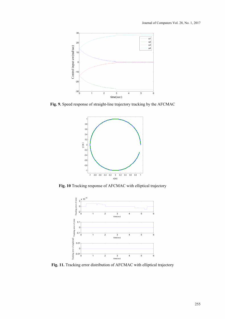
Fig. 9 plots the speed response of the straight-line trajectory tracking of the AFCMAC, and reveals
smooth, stable speed responses.
Fig. 10 shows an input-output diagram that is derived from the commands associated with the elliptical
trajectory tracking of the desired input cos( ), sin( ), 0d d dx t y t θ= = = . The results of a system simulation
suggest that the AFCMAC exhibits favorable tracking performance when used along an elliptical path.
Fig. 11 plots the tracking error distribution of the AFCMAC for the elliptical trajectory, and the track-
ing errors in elliptical trajectory tracking exhibit favorable convergence.
Fig. 12 plots the speed response of the elliptical trajectory tracking of the AFCMAC, verifying the
smooth, stable speed of the device.
Journal of Computers Vol. 28, No. 1, 2017
255
0 1 2 3 4 5 6-30
-20
-10
0
10
20
30
time(sec)
Co
ntr
ol
inp
ut
uw
(rad
/sec
)
u1
u2
u3
u4
Fig. 9. Speed response of straight-line trajectory tracking by the AFCMAC
-1 -0.8 -0.6 -0.4 -0.2 0 0.2 0.4 0.6 0.8 1
-1
-0.8
-0.6
-0.4
-0.2
0
0.2
0.4
0.6
0.8
1
x(m)
y(m
)
Fig. 10 Tracking response of AFCMAC with elliptical trajectory
0 1 2 3 4 5 6-2
0
2x 10
-16
time(sec)
Tra
ckin
g e
rro
r o
f x
(m)
0 1 2 3 4 5 6-0.1
0
0.1
time(sec)
Tra
ckin
g e
rro
r o
f y(m
)
0 1 2 3 4 5 6-0.01
0
0.01
time(sec)Tra
ckin
g e
rror
of
angle
(rad
)
Fig. 11. Tracking error distribution of AFCMAC with elliptical trajectory

The Tracking Control Design of Adaptive Fuzzy CMAC for an Omni-Directional Mobile Robot
256
0 1 2 3 4 5 6-20
-15
-10
-5
0
5
10
15
20
time(sec)
Co
ntr
ol
inp
ut
uw
(rad
/sec)
u1
u2
u3
u4
Fig. 12 Speed response of elliptical trajectory tracking by AFCMAC
4 Experiment Results
4.1 Design of Hardware of Omni-Directional Mobile Robot
As presented in Fig. 13, the experimental Qsys-based omnidirectional mobile service robot has the fol-
lowing components; (i) one compact personal computer (PC); (ii) four encoders that are mounted on the
driving motors; (iii) one 12V battery; (iv) four DC12V brushless servomotors and their drivers; (v) one
four-wheel omnidirectional platform and its controller on an Altera DE2-115 development board, and (vi)
eight laser scanners. Four driving omnidirectional wheels are driven by three DC12V brushless servomo-
tors with four mounted encoders. The proposed controller was implemented using C/C++ code and stan-
dard programming techniques in the Altera Nios II embedded processor. The FPGA chip integrated the
embedded processor, RTOS, and VHDL-based IP circuits to perform the adaptive control of the mobile
platform. All of the experiments were performed using system parameters L=20 cm and r=5.08 cm.
Fig. 13. Comprehensive physical map of experimental omni-directional mobile robot

Journal of Computers Vol. 28, No. 1, 2017
257
4.2 Use of AFCMAC in Trajectory Tracking
Tracking of Point-to-Point Positions. First, the initial parameters of both feedback timing and target
trajectory are specified, as follows.
1. Initial parameters for feedback timing
0.1 (s)ft =
where ft is the time that is taken by the embedded system to receive feedback from the motor of the
omni-directional mobile robot.
2. Initial parameters of target trajectory
Initial coordinate: [ ] [ ]0 0 00 (cm) 0 (cm) 0 (rad)x y θ = ;
objective function: [ ] 100 cos (cm) 100 sin (cm) 0 (rad)4 4
r r r
n nx y
π πθ
⎡ ⎤⎛ ⎞ ⎛ ⎞= ⋅ ⋅⎜ ⎟ ⎜ ⎟⎢ ⎥
⎝ ⎠ ⎝ ⎠⎣ ⎦
where 1, ,8n = � .
Fig. 14 presents a diagram of the experiment in which an AFCMAC performs point-to-point tracking
of a smooth trajectory. Clearly, when the proposed AFCMAC is utilized in an omni-directional mobile
robot in point-to-point tracking control, the robot can move from its starting point to the precise location
of the target.
-100 -80 -60 -40 -20 0 20 40 60 80 100
-100
-80
-60
-40
-20
0
20
40
60
80
100
X(cm)
Y(cm)
Actual path
Desired path
Fig. 14. Experiment on AFCMAC in point-to-point tracking response
Straight-Line Tracking Trajectory. A straight path is designed with the initial point at ( (0), (0)) (0,0)d dx y =
and the final point at ( , ) (100,100)d dx y = . (The initial point ( (0), (0)) (50,0)x y = on the straight path,
along which the omni-directional mobile robot moves, is utilized to achieve trajectory tracking control.
Fig. 15 shows the tracking response of the AFCMAC with a straight-line trajectory. The figure reveals
that the proposed AFCMAC controls an omni-directional mobile robot with any initial point and per-
forms accurate straight-line trajectory tracking.

The Tracking Control Design of Adaptive Fuzzy CMAC for an Omni-Directional Mobile Robot
258
0 10 20 30 40 50 60 70 80 90 1000
10
20
30
40
50
60
70
80
90
100
X(cm)
Y(c
m)
Actual path
Desired path
Fig. 15. Experiment on tracking response of AFCMAC for straight-line trajectory
Fig. 16 displays the experiment on the tracking error distribution of the AFCMAC with a straight-line
trajectory. The figure reveals that as time passes, tracking errors along the straight-line trajectory con-
verge consistently.
0 10 20 30 40 50 60 70 80 90 100 110-10
0
10
20
30
40
50
Time(0.1 sec)
Tra
ck
ing
err
ors
Tracking error of x (cm)
Tracking error of y (cm)
Tracking error of θ (rad)
Fig. 16. Experiment on tracking error distribution for straight-line trajectory
Elliptical Trajectory Tracking. Parameters for an elliptical path are as follows.
100cos( )
150sin( ) ,0 2
0
d
d
d
x
y
θ
θ θ π
θ
=⎧⎪
= ≤ ≤⎨⎪ =⎩
and 0 2θ π≤ ≤ (21)
The initial point is ( (0), (0)) (100,0)d dx y = and the final point is ( (2 ), (2 )) (100,0)
d dx yπ π = . (The ini-
tial point ( (0), (0)) (0,0)x y = on the elliptical path, along which the omni-directional mobile robot moves,
is used to achieve trajectory tracking control.
Fig. 17 displays the experiment on the tracking response of the AFCMAC along an elliptical trajectory.
The figure verifies that the proposed AFCMAC controls an omni-directional mobile robot with any initial
point and can perform accurate elliptical trajectory tracking.

Journal of Computers Vol. 28, No. 1, 2017
259
-150 -100 -50 0 50 100 150-200
-150
-100
-50
0
50
100
150
200
X(cm)
Y(cm)
Actual path
Desired path
Fig. 17. Experiment on tracking response of AFCMAC with elliptical trajectory
Fig. 18 presents an experiment on the tracking error distribution of AFCMAC with a straight-line tra-
jectory. The figure reveals that as time passes, tracking errors with the elliptical trajectory converge con-
sistently.
0 100 200 300 400 500 600-100
-80
-60
-40
-20
0
20
Time(0.1 sec)
Tra
ckin
g e
rro
rs(c
m)
Tracking error of x (cm)
Tracking error of y (cm)
Tracking error of θ (rad)
Fig. 18. Experiment on tracking error distribution of AFCMAC with elliptical trajectory
5 Conclusions
This work proposed a modified AFCMAC scheme that is used in the trajectory tracking control of a four-
wheeled omni-directional mobile robot. The proposed scheme can be used to solve the tracking control
problem of a class of nonlinear uncertain systems. The fuzzy cerebellar model is combined with both
adaptive and control laws to enable the controller gains or weights to be adjusted online. The FCMAC is
trained to approximate the optimal weights, with the CMAC trained in 49 input states to have a high
resolution, so that the error between the input and the desired output is small. The AFCMAC in all in-
stances an output feedback sliding-mode control algorithm and ideal adaptive and control laws to reduce
its tracking error to zero and to accommodate its approximation error.
Finally, the proposed AFCMAC scheme is implemented on a field-programmable gate array chip,
completing the co-design of hardware and software. The Qsys system is used to present results of the
simulation of the real-time trajectory tracking control of the omni-directional mobile robot to demonstrate
the effectiveness and the high performance of the proposed AFCMAC.

The Tracking Control Design of Adaptive Fuzzy CMAC for an Omni-Directional Mobile Robot
260
References
[1] J.J.E. Slotine, W. Li, Applied Nonlinear Control, Prentice-Hall, 1991.
[2] G. Maione, High-speed digital realizations of fractional operators in the delta domain, IEEE Transactions on Automatic
Control 56(3)(2011) 697-702.
[3] Z.Y. Shen, J. Zhao, J. Xu, X.S. Gu, Nonlinear unknown input observer design by LMI for Lipschitz nonlinear systems, in:
Proc. of The 8th World Congress on Intelligent Control and Automation (WCICA), 2010.
[4] F.H. Hsiao, Delay-dependent exponential optimal H-infinty synchronization for Nonidentical chaotic systems via neural-
network-based approach, Abstract and Applied Analysis (Article ID 294892), 2013.
[5] K.S. Narendra, K. Parthasarathy, Identification and control of dynamical systems using neural networks, IEEE Transactions
on Neural Networks 1(1)(1990) 4-27.
[6] J.R. Noriega, H. Wang, A direct sdaptive neural-network control for unknown nonlinear systems and its application, IEEE
Transactions on Neural Networks 9(1)(1998) 27-34.
[7] T. Takagi, M. Sugeno, Fuzzy identification of systems and its application to modeling and control, IEEE Transactions on
Systems, Man, and Cybernetics 15(1)(1985) 116-132.
[8] C.W. Tao, Adaptive fuzzy PIMD controller for systems with uncertain Deadzones, IEEE Transactions on Systems, Man, and
Cybernetics, Part A 32(5)(2002) 614-620.
[9] W.S. Lin, C.S. Chen, Robust adaptive sliding mode control using fuzzy modelling for a class of uncertain MIMO nonlinear
systems, IEE Proceedings - Control Theory and Applications 149(3)(2002) 193-201.
[10] J. S. Albus, A new approach to manipulator control: The cerebellar model articulation controller (CMAC), Journal of Dy-
namic Systems, Measurement, and Control 97(3)(1975) 220-227.
[11] T.F. Wu, P.S. Tsai, F.R. Chang, L.S. Wang, Adaptive fuzzy CMAC control for a class of nonlinear systems with smooth
compensation, IEE Proceeding- Control Theory and Applications 153(6)(2006) 647-657.
[12] H.C. Huang, Intelligent motion control for four-wheeled omnidirectional mobile robots using ant colony optimization, Next
Wave in Robotics: Communications in Computer and Information Science 212(2011) 94-106.
[13] T.F. Wu, H.C. Huang, S.S.-D. Xu, N.T. Hu, Adaptive fuzzy CMAC controller design for tracking of four-wheeled omnidi-
rectional mobile robot, Innovation, in: T.H. Meen, S.D. Prior, & A.D.K.T. Lam (Eds.), Communication and Engineering-
Meen, Taylor & Francis Group, London, 2013, pp. 341-346.


