
Thruster Disc Brake SB 23/SB 28/SB 38
A1
Reliable Self-Centering High Performance Robust Design Easy Maintenance
A4100040000390003800037000360003500034000330003200031000300002900028000270002600025000240002300022000210002000019000180001700016000150001400013000120001100010000
900080007000600050004000300020001000
0
Brak
e to
rque
in N
m
SB 2
8
SB 3
8
SB 23
355 400 450 500 560 630 710 800 900 1000 1250
Brake disc diameter in mm
PINTSCH BUBENZERis certified according to
DIN EN ISO 9001:2000
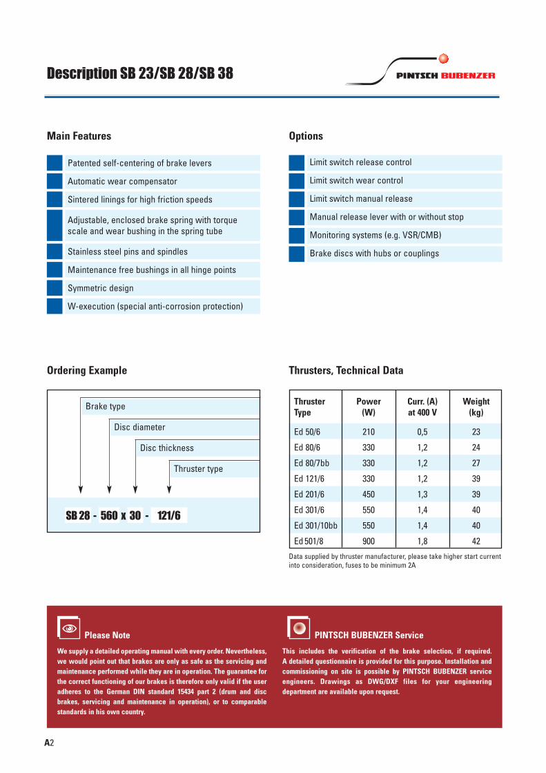
Description SB 23/SB 28/SB 38
SB 28 - x -560 30 121/6
A2
Disc diameter
Disc thickness
Thruster type
Brake type
Patented self-centering of brake levers
Main Features
Limit switch release control
Options
Automatic wear compensator Limit switch wear control
Limit switch manual releaseSintered linings for high friction speeds
Manual release lever with or without stop
Monitoring systems (e.g. VSR/CMB)
Brake discs with hubs or couplingsStainless steel pins and spindles
Maintenance free bushings in all hinge points
Adjustable, enclosed brake spring with torquescale and wear bushing in the spring tube
Please Note
We supply a detailed operating manual with every order. Nevertheless,we would point out that brakes are only as safe as the servicing andmaintenance performed while they are in operation. The guarantee forthe correct functioning of our brakes is therefore only valid if the useradheres to the German DIN standard 15434 part 2 (drum and discbrakes, servicing and maintenance in operation), or to comparablestandards in his own country.
PINTSCH BUBENZER Service
This includes the verification of the brake selection, if required. A detailed questionnaire is provided for this purpose. Installation andcommissioning on site is possible by PINTSCH BUBENZER serviceengineers. Drawings as DWG/DXF files for your engineering department are available upon request.
�
Ordering Example
Symmetric design
W-execution (special anti-corrosion protection)
Data supplied by thruster manufacturer, please take higher start currentinto consideration, fuses to be minimum 2A
ThrusterType
Power (W)
Curr. (A)at 400 V
Weight(kg)
Ed 50/6
Ed 80/6
Ed 80/7bb
Ed 121/6
Ed 201/6
Ed 301/6
Ed 301/10bb
Ed 501/8
210
330
330
330
450
550
550
900
0,5
1,2
1,2
1,2
1,3
1,4
1,4
1,8
23
24
27
39
39
40
40
42
Thrusters, Technical Data

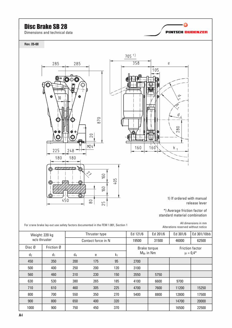
Rev. 05-08
Disc Brake SB 23Dimensions and technical data
Weight: 97 kgw/o thruster
Thruster type
Friction factor μ = 0,4*
Disc Ø Friction Ø
d2
355
400
450
500
560
630
d1
275
320
370
420
480
550
d4
155
200
250
300
360
430
e
137,5
160
185
210
240
275
k1
72,5
95
120
145
175
210
935
1085
1255
1425
1630
1870
1600
1850
2100
2400
2750
2050
2370
2690
3070
3520
Contact force in N
Ed 50/6
8500
Ed 80/6
12500
Ed 80/7bb
16000
Brake torqueMBr in Nm
A3
A
1) If ordered with manualrelease lever
*) Average friction factor ofstandard material combination
All dimensions in mmAlterations reserved without noticeFor crane brake lay-out use safety factors documented in the FEM 1.001, Section 1
Rev. 05-08
Weight: 220 kgw/o thruster
Thruster type
Friction factor μ = 0,4*
Disc Ø Friction Ø
d2
450
500
560
630
710
800
900
1000
d1
350
400
460
530
610
700
800
900
d4
200
250
310
380
460
550
650
750
e
175
200
230
265
305
350
400
450
2700
3100
3550
4100
4700
5400
5750
6600
7600
8800
9700
11200
12800
14700
16500
15250
17500
20000
22500
Contact force in N
Ed 121/6
19500
Ed 201/6
31500
Ed 301/6
46000
Ed 301/10bb
62500
Brake torqueMBr in Nm
A4
Disc Brake SB 28Dimensions and technical data
All dimensions in mmAlterations reserved without notice
*) Average friction factor ofstandard material combination
1) If ordered with manualrelease lever
For crane brake lay-out use safety factors documented in the FEM 1.001, Section 1
k1
95
120
150
185
225
270
320
370

A5
Weight: 510 kgw/o thruster
Thruster type
Disc Ø Friction Ø
d1
580
670
770
870
1120
d4
350
440
540
640
890
e
290
335
385
435
560
k1
180
225
275
325
450
21000
24500
28000
31500
40500
Contact force in N
Ed 501/8
91000
Brake torque MBr in NmFriction factor μ = 0,4*d2
710
800
900
1000
1250
Disc Brake SB 38Dimensions and technical data
Rev. 12-06
All dimensions in mmAlterations reserved without notice
*) Average friction factor ofstandard material combination
1) If ordered with manualrelease lever
For crane brake lay-out use safety factors documented in the FEM 1.001, Section 1


