
RIGHT:
URL:
CITATION:
AUTHOR(S):
ISSUE DATE:
TITLE:
High pressure apparatus : ram-in-tie-bar multianvil presses
Hall, H. Tracy
Hall, H. Tracy. High pressure apparatus : ram-in-tie-bar multianvilpresses. The Review of Physical Chemistry of Japan 1967, 37(2): 63-71
1967
http://hdl.handle.net/2433/46900

The Review of Physical Chemistry of Japan Vol. 37 (1967)
TIfE REVIEW OP PHYSICAL CHEAfrSiRY OP JAPAY., ~'aL. 31, No. 2, 1961
HIGH PRESSURE APPARATUS: RAM-IN-TIE-BAR
MULTIANVIL PRESSES
By H. TRACY HALL
A mul[iaxial press is described in which pressing members such as anvils,
punches, pistons, and dies are brought together along a plurality of geometrical aces by a contracting framework. These pressing members impinge upon an appro-
priate cell to generate pressure. The cell and/or its contents may be heated or cooled while under pressure by esternal or internal means. The preferred embodi-ment of this apparatus can be envisioned by substituting pull-type hydraulic rams for the fixed, rigid tie bars of a conventional multianvil press such as a tetrahedral
press. Thus the ''Ram-In-Tie-Bar' (RITB) press has variable length tie bars. The base mounted push-type ram of the conventional press is replaced by a 5xed post to which an anvil is attached. The new press has a number of advantages over conventional multianvil presses which are equipped with an anvil guide:
(1) The Ram-In-Tie-Bars serve as an integral anvil guide, thus eliminating the need for the usual guide. This greatly increases the working space in
[he anvil region and facilitates the use of X-ray diffraction devices and other equipment is conjunction with the press.
(2) The total ram tonnage required to obtain the same anvil load is reduced. Thus total RITB tonnage for a tetrahedral system is only 0.6123 that of
a standard (rigid tie means design) tet press and for a cubic system is only 0.7071 times the total ram tonnage of a standard cubic press.
(3) Larger presses of RITB design can be built than can be built in standard design
(4) RITB presses are less expensive than conventional types, especially in the larger sizes.
(5) The use of external heating and cooling is greatly facilitated in the new press.
Introduction
The prototype multianvil high pressure apparatus, a tetrahedral press, was described in 1958[1.
In multianvil presses the moving pressure inducing element usually consists of a relatively incom-
pressible body that has a generally prismatic-shaped working end. This is called as anvil. Anvils
are aormally~constructed of cemented tungsten carbide, the most resistant material to breakage by
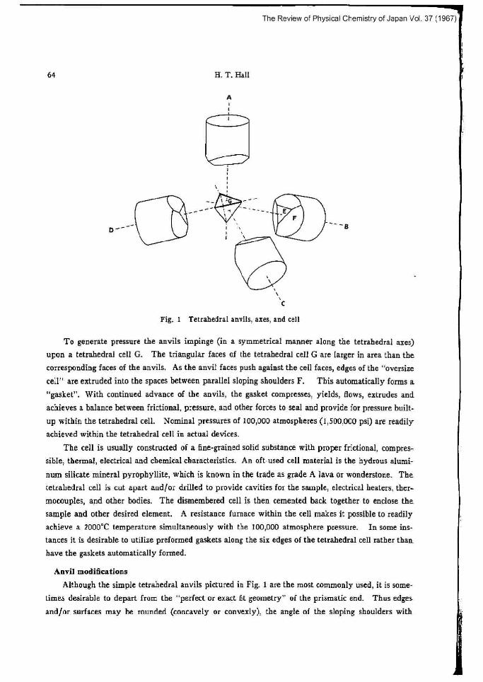
compression currently available. Simple tetrahedral anvils are shown in Fig. 1. The anvils depicted,
which have triangular faces E and sloping shoulders F on the working end, will fit perfectly together
when moved inwardly along the tetrahedral axes A, B, C, and D. When so fitted, they completely
enclose a regular tetrahedral void. The anvils of a multianvil press are thrust together by mechanical,
hydraulic,.or other means.
(Raccived January 3, 7068) 1) H. T, Hall, Rev. Sci. Inrtr., 29, 267 (1958), See also U. S. Patent No. 2,918,699, Den 29, 1959
The Review of Physical Chemistry of Japan Vol. 37 (1967)
64 H. T. Hall
A
o -_
d-E
F ~_ 'B
~~ ,\ .
t
Fig. 1 Tetrahedral anvils, aces, and cell
To generate pressure
upon a tetrahedral cell G.
corresponding faces of the
cell" are extruded into the "gasket". With continued
achieves a balance between
up within the tetrahedral c y
achieved within the tetrahedral cell in actual devices.
The cell is usually constructed of afine-grained solid substance with proper frictional, compres-
sible, thermal, electrical and chemical characteristics. An oft-used cell material is the hydrous alumi-
num silicate mineral pyrophyllite, which is known in the trade as grade A lava or wonderstone. The
tetrahedral cell is cut apart wd/or drilled to provide cavities for the sample, electrical beaters, ther-
motovples, and other bodies, The dismembered cell is then cemented back together to enclose the
sample and other desired element. A resistance (umace within the cell makes it possible [o readily
achieve a 2000°C temperature simultaneously with the 100,000 atmosphere pressure. Ia some ins-tances it is desirable to utilize preformed gaskets along the six edges of the tetrahedral cell rather than
Gave the gaskets automatically formed.
Anvil modifications
Although the simple tetrahedral anvils pictured in Fig. 1 are the most commonly used, it is some-
times desirable to depart from [he "perfect or exact 5t geometry" of the prismatic end. Thus edges
and/or surfaces may be rounded (concavely or convexly), the angle of [he sloping shoulders with
the anvils impinge (in a symmetrical manner along the tetrahedral axes)
The triangular faces of the tetrahedral cell G are larger in area than the
anvils. As the anvil faces push against the cell faces, edges of the "oversize
spaces between parallel sloping shoulders F. This automatically forms a
advance of the anvils, the gasket compresses, yields, flows, extrudes and
frictional, pressure, and other forces to seal and provide for pressure built-
ell. Nominal pressures of 100,000 atmospheres (1,500,000 psi) are readil

The Review of Physical Chemistry of Japan Vol. 37 (1967)
a
High Pressure Apparatus: Ram-In-Tie-Bar Multianvil Presses 65
respect [o the face may be vazied or may be sloped at one angle for a distance and then at another
angle for an additional distance, or the shoulder farm may be curved or contoured. The same is true
for the form of the face. These modifications give anvils that fit imperfectly together with respect to
the manner in which the simple anvils fit. Explained in other words, the shoulders F do not contort
each other over their entire surfaces when the anvils are brought together without a cell being present.
Also, the "void" formed by the anvils in contact may only approximate the shape of a tetrahedron.
In addition, the void may not be totally enclosed by the contacting anvils. Modified anvils, by achie-
ving amore delicate balance of the forces and other factors involved in pressure generation, have made
it possible to obtain pressures considerably beyond 100,000 atmospheres. Regular tetrahedral cells
may be used with modified anvils, although it is omen preferable to use cells conforming to the shape
of the anvil ends. Mo]ded, inorganic and filled plastic cells conforming to the exact shape of the
working ends of the anvils have been extensively used in the Brigham Young University High Pres-
sure Laboratory. Such cells have been used withand without molded, preformed gaskets.
Higher order presses
A hexahedral or cubic anvil system is shown in Fig. 2. In a cubic press. six anvils with square
faces are thrust together to impinge upon acube-shaped cell which again may o[ may not have pre-
formed gaskets along its edges. Other features and modifications discussed above relating to tetrahedral
presses apply equally well to cubic presses. Obviously the multianvil press concept includes octa-
hedral .presses, prismatic presses and higher order geometrical configurations.
z
X, ,Y
i
G
i
.EF
i i i
Fig. 2 Cubic anvils, axes, and cell
x

The Review of Physical Chemistry of Japan Vol. 37 (1967
66 H. T. Hall
IC is interesting to note that a cubic press is atriaxial device (the anvils move along three inde-
pendent axes to generate the pressure), whereas a tetrahedral press is tetraxial; i. e., the anvils move along four independent axes. Considering the active and reactive forces acting on a small, semi-fluid
(under pressure) solid sample centered in a pyrophyllite tetrahedral or cubic cell, the sample "sees" a more "hydrostatic" pressure in a tetrahedral system than it does is a cubic.
Anvil guides-space problems
A major improvement in multianvil presses came in 1962 with the invention of the anvil guide2~.
This device synchronizes and coordinates the motion of the anvils so that they advance uniformly and
simultaneously toward the center of the press. It also eliminates anvil alignment problems [hat were
present in early presses. The anvil guide, however, ordinarily occupies considerable space is the vicinity of [he anvils and reduces the working room Chere. This presents problems wben certain
equipment (such as an X-ray diifrazmme[er, an external heating furnace, or a cooling system) is used
in conjunction with an anvil press, because the guide mechanism is in the way. Note that an anvil
guide mechanism was not used in the hydraulically actuated X-ray diffraction press described by Bar-net[ and Hallal. Rather, each hydraulic ram was individually valued for ingress and egress of hy-
draulic oil, and anvil position was monitored by means of dial indicator gages. Coordination of anvil
motion was manually controlled by the operator as was done in the early tetrahedral presses. The
improved multianvil press described below provides new means far synchronizing and coordinating
anvil motion and provides for open space in the vicinity of the anvils. Also, the new press, which is
called a "Ram-In-Tie-Bar" (RITB) press, possesses some additional advantages in its own right.
Ram-In-Tie-Bar Presses
A drawing of a hydraulic RITB tetrahedral (tet) press is shown in Fig. 3. An actual press would
be much more wmpact, hu[ this press has been "stretched-out" along its te[ axes for illustrative pur-
poses. In a conventional tie bar press, anvil motion is usually provided by rams or jacks mounted on
bases which are held in fined position by tie bars. In a tet press, there would be four push-type
rams'[ with an anvil mounted on the moving end of each ram. The rams, of course, would advance
the anvils toward the center of a tetrahedron defined by the tie bar saes. The tie bazs, together with
the bases, provide a rigid framework to support the thrust of the rams. Across section of a conven-
tional hydraulically-actuated tet press is shown in Fig. 4. A RITB tet press, in contrast to a conven-
tional tet press, utilizes six pull-type rams or jacks. Each ram or jack replaces one fined tie bar is the
conventional press (see Fig. 5) giving, in effect, a tie bar of variable length. The rams that are
z) 3)
H, T. Hall, Rev. Sci. Inrtr., 33, 1278 (1962), See also U. S. Patent No. 3,182,353, May 11, 1965 J. D. Barnett and H. T. Hall, ibid., 35, 175 (1964), See also U. S. Patent No. 3,249,753, Mey 3,1966 Most rams "pull" es well as "push". However, when a ram's primary function is to push (usually by extending iu length) it is called a push ram. Its major work is done during the push cycle, During the pull cycle, secondary work (usually only retraction of the working components) is performed. Likewise, the primary function of a pull ram is to move its main work load during a pull cycle (usually by contraction or shortening of the ram).
3

The Review of Physical Chemistry of Japan Vol. 37 (1967)e
High Pressure Apparatus: Ram-In-Tie-Bar Multianvil Presses 67
A
i
D"
M
e N
E
F
J
M•~ .___~`_
O
a G
O
---a
Fig.
V~ ~̀C
3 A hydraulically powered Ram•In-Tie-Bar tetrahedral press The lines A, $ C, D which intersect at M are the tetrahedral axes of
the press along which the anvils move. The triangular faced tetra- hedral anvils are mounted an the freeends of the anvil posts ]. These
posts are tasteaed to the bases K which are caused to move in and out along the tetrahedral axes by the put] rams E. Hydraulic oil, under
pressure, enters the ram at G, causing retraction of the rod F into the hydraulic cylinder. This action causes the anvils to move synchro-
nously toward the center of the press M. Hydraulic oil entering at H expands the press musing the znvils to move away from M,
normally mounted on the bases are replaced with fixed posts to which the anvils are attached. The
anvils are thrust together by the "pull" of the "in-tie-bar' rams rather than by the "push" of the rams
in conventional design. Whea hydraulically actuated pull-type rams are used in RITB presses, they
are designed according to principles previously givenal. Hydraulic oil is simultaneously admitted to
all rams to either advance or tetrad them.
Integral anvil guide
A most interesting feature of a RITB press is that the rams in the tie bars serve as an integral
anvil guide system. The mechanical constraints on the entire assemblage of Ram-In-Tie-Bars and bases
are such that all the bases (and hence all the anvils) must move simultaneously, equally, and in com-
plete coordination toward the center of the press. As can readily be seen from the figures, [his new
arrangement provides much more open space in the vicinity of Ure anvils.
4) $ T. Hall, Rev. Sci. Insls., 37, 568 (1966)

The Review of Physical Chemistry of Japan Vol. 37 (1967)
68 H. T. Hal]
deerrid cer..crbn. m.ril bin6~ng r/mR\
W~[ / elrtlricol wurWtimbaR-w bbd ~
boce /(irgWd wiq mrn~ /
.~ ~~ ~r~oil :eda/
1
O
1_ ~ ri.-ber _ _ _
CRJSS SECTION CONVENnOWt TFT MESS
Fig. 4 Plane section through aces of two hydraulic rams of conventional tetrahedral press
cross 3WTION slTe v.ea l~.el
emll «<ecc agile m .a«~M~ en.il.
4lnNnq .Me
el«Mul incule/ion
.LC~NCOI cexuctlm. e..e.,,p ei..~
md~ ro.~
\\
Faa~e~.
`~~
~b~
.man ble
`eil .. _k
.atmc. eil inla / \od..nu e11 uba
hll Tne Xyd.aulic R=m
Fig. S Plaoe section through ues of two anvil posts in Ram-In-Tie•Bar tetrahedral press
actuated by a Dull-type hydraulic ram
External heatfng and cooling advantages
In multiaavil presses it is usually desirable to electrically isolate the anvils from each other in
order that the anvil faces may serve as electrical coanedors to resismnce heating elements or other
devices located within the pressure cell. This has usually been accomplished by placing insulation as
shown in Fig. 4. In the RITB arrangement, it is desirable to place the electrical insulation at the
bottom of the anvil post. This moves the insulation away from the anvil region where unit compres-
sive stresses are high and places it in a location where the loading per unit area upon the relatively
soft plastic laminates used for electrical insulation can 6e reduced. WiW this accomplished, all com-
ponents in the anvil region can be constructed of metal. This makes it possible to beat the anvils

The Review of Physical Chemistry of Japan Vol. 37 (1967)
High Pressure Apparatus: Ram-In-Tie-Bar MultianviL Presses 69
(and consequently [he enclosed pressure cell and its contents) by an external furnace without burning •or overheating the plastic electrical insulation. It is desirable to construct the anvil post of a law
thermal conductivity material, such as stainless steel, to provide a favorable situation for either beating •or cooling the anvils by external means. In the latter instance. liquid nitrogen or other coolant canbe
circulated around the anvils to perform experiments at low temperatures. The size and mass of an -anvil post is much less, of course, than that of a hydraulic ram. Consequently. the anvil region can
more easily be heated or cooled without excessive transfer of heat. Also, [he post can more readily be
constructed of a low thermal conductivity material than can an entire ram. In addition, the anvil
post can be relatively long and slender, thus providing a long heat path. A push-type ram must, of necessity, be rather bulky and constitutes a large heat sink.
Base diameter reductions 9nother advantage of RITB presses is the fact that the bases (K of Fig. 3) can be considerably
seduced in diameter and thickness over that required is a conventional press where apush-type ram
is mounted on the base. The push-type ram, being much larger in diameter than the post of Fig. 3,
requires a correspond+_ngly larger diameter base. This requires the tie baz ends to be fastened to the
base at a greater distance from the base center line. Thus a thicker base must be used to give the
same support. The decreased size of the bases in the RITB press allows the threaded ends of [he tie
bars (or the ends of other style fasteners) to be moved in closer to the center line of the base/anvil -axes.
Access hole to sample
The crass sectional diagram of a RITB let press of Fig. 5 shows an "access hole" extending from
the bottom of the base through [he anvil post, the back up block, and the anvil, oa into the sample.
.Similar access holes have been described hefore is connection with providing means for entrance of an
X-ray beam to the sample in a conventional tetrahedral press>. I3owever, because of the fact that a -h
ydraulic ram was mounted on the base, the ram piston had to be hollowed and access from outside was through a section of the piston perpendicular [o the ram axis followed by a section along the ram
.axis. In other words, the path from the outside traversed a right angle bend before reaching the
sample. Additional complications arose because of the limited hollowed-out space available is the
.piston of the ram and also from the fact that the piston moved with respect to a stationary cylinder. In contrast to this, note the simple, uncomplicated, "line of sight" access hole in a RITB. In the con-
ventional X-ray diffraction tet press the X-ray tube had to be mounted directly inside a moving ram in
.a crowded, inconvenient, complicated manner. In a RITB press X-ray tubes or other appliances can -be mounted oa the bottom of a base, outside the press, where there is plenty of room for arranging the
various parts.
Higher order RITB presses
The RITB concept is not limited to tetrahedral presses, but can be applied equally well to hexa-
hedral (cubic), octahedral and prismatic presses, and to any type of regular or irregular, symmetrical
ar asymmetrical multianvil type device.

The Review of Physical Chemistry of Japan Vol 37 (1967
70 H. T. Hall
Tonnage, stroke, size, and cost comparisons
Some compazisoas between RITB and conventional designs for tet and cubic presses are of inte-
rest. Consider, for example, a standard 20o ton tet press. This is a common research siu instrument.
in which each of the four push-type rams is of 200 ton capacity. In a RITB tet press of the same
capacity, [he six pull-type rams would each be of 82 ton size- N'hen the sin RITB rams are each
exerting an 82 ton pull on the connecting bases, geometry dictates that the thrust along [he~ anvil post
axes equals 200 tons (the same as the thrust of the 200 ton push rams located on equivalent axes in a
conventional design). The total ram tonnage for such a press would be 6 x 82=492 toss compared to
4 X 200=800 tons for a Conventional tet press,
Now consider a 200 ton cubic press. The standard design would use six push-type rams of 20(}
tons each (total tonnage is 6 x 200=1200). The new design uses 12 each, 71 ton pull-type rams (total tonnage is 12 x 71=852) to accomplish the same purpose.
While the total ram tonnage in [he new RITB designs is smaller than in conventional designs, the.
ram stroke (the motion required of [he ram to move the anvils unit distance) is proportionately lazger.
For tet presses the RITB design requires 1.632 times the ram stroke of the conventional design. In-
dividual RITB pull rams are 0.4082 the rapacity of the conventional push-type rams, and total ram
tonnage is only 0.6123 times that of the conventional design. The corresponding fados for cubic
presses are 1.414 times the ram stroke, 0.3535 times the individual ram tonnage, and 0.7071 times the total ram tonnage.
The increase in ram stroke required in RITB presses is readily obtained at insignificant additional
cost and increase is siu because the anvil motion required in all multianvil presses is relatively small.
The decrease in total ram tonnage in RITB presses, on the other hand, results in significant reductions
in size, weight, and cost. This particularly comes to light when very large presses are considered. For example, if it were desired to construct a conventional cubic press oC 10,000 tons capacity (the siu-
of each individual ram) it would 6e difficult to find a manufacturer who could produce rams of this-
size for this use. The pull-type rams in an equivalent capacity RITB unit, however, would be only
3550 toss in siu. These could be fabricated much more readily than the 10,000 loo push-type rams.
In standard machine shop practice there is a region in which the cost of fabricating larger and larger
pieces of equipment rises steeply. Under such circumstances, if it is possible to redesign a machine so that it contains a larger number of smaller pacts, a considerable reduction in cost can be achieved_
The RITB press offers this particular advantage over the more conventional multianvil high pressure-
devices. In addition, because of machine tool size limitations, it offers the possibility of constructing:
lazger presses than would be possible with conventional design.
Sore guide
While the idealized mechanical constraints imposed by [he RITB geometry insure perfect align--
meat and motion of the anvils, practical consideratfoas of machining tolerances, clearances of sliding-
6ts in the rams, and friction may allow too much anvil position error for very enacting experimental
situations. When it is needed, a simple, geometrically redundant mechanism is of value in improving
the precision of anvil motion is RITB devices. It is called the "sure-guide" and is shown in Fig. 6

The Review of Physical Chemistry of Japan Vol. 37 (1967)
High Pressure Apparatus: Ram-In-Tie-Bar Multianvil Presses 7I
.~ .~ ~=t=.
Fig. 6 `Sure-fiuide" for ultra prttiu
anvil positiaaiag is RITB tetra-
hedralpress
Similar sure-guides caa be used
with Cubit aad other mul[iaavil
high pressure apparatus.
for use with RITB tet presses. The sure-guide fits around the anvil posts of Fig. I at a distance suffi-
ciently removed from the anvils to be out of the aay. As the anvils move in and out with respect to
[he center of the press, the anvil posts slide within the bearing surfaces of the sure-guide. This bearing
surface may be electrically insulating. Obviously the sure-guide principle pictured for a tet press in
Fig. 6 can be used with cubic, octahedral, prismatic and other RITB multianvil presses.
The illustrations of [his article show bydraulfcally impelled rams or jacks as means for activating
the press. It is evident that mechanical, electrical or any other means of motive power may be used
to actuate a RITB press while still maintaining the novel advantages and features enumerated above.
Brigham Young Universfly
Proud. Ulah 89601


