
Loughborough UniversityInstitutional Repository
Torsional and bendingvibration measurement on
rotors using laser technology
This item was submitted to Loughborough University's Institutional Repositoryby the/an author.
Citation: MILES, T.J. ... et al, 1999. Torsional and bending vibration mea-surement on rotors using laser technology. Journal of Sound and Vibration, 226(3), pp. 441 - 467.
Additional Information:
• This article was accepted for publication in the Journal of Sound andVibration [Elsevier c© Academic Press]. The definitive version is availableat: http://dx.doi.org/10.1006/jsvi.1999.2253
Metadata Record: https://dspace.lboro.ac.uk/2134/19748
Version: Accepted for publication
Publisher: Elsevier ( c© Academic Press Ltd)
Rights: This work is made available according to the conditions of the Cre-ative Commons Attribution-NonCommercial-NoDerivatives 4.0 International(CC BY-NC-ND 4.0) licence. Full details of this licence are available at:https://creativecommons.org/licenses/by-nc-nd/4.0/
Please cite the published version.

TORSIONAL AND BENDING VIBRATION MEASUREMENT ON ROTORS USING LASER TECHNOLOGY
T.J. MILES*, M. LUCAS**, N.A. HALLIWELL and S.J. ROTHBERG
Department of Mechanical Engineering, Loughborough University, UK.
*Now at Rolls-Royce Strategic Research Centre, Derby, UK
**Now at Department of Mechanical Engineering, University of Glasgow, UK.
Total Number of Main Text Pages: 30
Total Number of Figures: 19 in 26 pieces
Short Title: TORSIONAL AND BENDING VIBRATION MEASUREMENT
Address for Correspondence:
Dr S.J. Rothberg
Department of Mechanical Engineering
Loughborough University
LOUGHBOROUGH
Leicestershire LE11 3TU.

TORSIONAL AND BENDING VIBRATION MEASUREMENT – Miles et al
2
SUMMARY
Based on the principles of laser Doppler velocimetry, the laser torsional vibrometer (LTV)
was developed for non-contact measurement of torsional oscillation of rotating shafts,
offering significant advantages over conventional techniques. This paper describes
comprehensive theory to account for the sensitivity of the LTV’s measurements to shaft
motion in all degrees of freedom. The optical geometry of the LTV offers inherent immunity
to translational motion of the target shaft, either axial or radial. However, its measurements
are sensitive to angular lateral vibration of the shaft. The significance of this sensitivity is
compared with the instrument noise floor and typical torsional and lateral vibration levels.
Optimum alignments of the instrument are then specified to ensure effective immunity to all
lateral motion in typical applications. To overcome this problem more reliably, a new
technique is proposed permitting unambiguous measurement of pure torsional vibration in
situations where use of a single LTV demonstrates unacceptable sensitivity to angular lateral
vibrations. Practical application of this technology is demonstrated with torsional vibration
measurements from a diesel engine crankshaft. Simultaneously, previously unattained
measurements of shaft bending vibration measurements are made. The first bending mode of
the crankshaft was identified and its vibration amplitude and damping estimated. This
application of laser vibrometry for non-contact measurements of shaft vibration represents a
further step forward in the use of this technology for machinery diagnostics.

1. INTRODUCTION
Torsional and bending vibrations are both important in rotating shaft systems. Typical
torsional vibration problems in automotive, marine propulsion and industrial applications
include oscillation of crankshafts, drive-shafts, and component wear in gearboxes. In these
cases shaft cracking, coupling deterioration and gear failure can result [1, 2]. A number of
situations can give rise to shaft bending (or, more generally, angular lateral) vibrations,
including unbalance, misalignment, bearing faults, rubs and the effects of gears, blades and
vanes [3]. Bending vibration of reciprocating engine crankshafts is particularly important in
automotive NVH studies. Low order bending vibrations are of concern in engine reliability
and high order vibrations are influential on power-plant noise and vibration [4]. Crankshaft
bending vibration is also believed to be the main source of engine ‘rumble’, a troublesome
low and mid-frequency noise that reduces passenger comfort, particularly during acceleration
[5]. The difficulty of obtaining measurements directly from rotating components has until
recently prevented routine experimental analysis of these quantities.
The measurement of translational vibration velocity (on non-rotating structures) with laser
Doppler velocimetry (LDV) [6] is now a well-established experimental technique. The basic
principle of LDV requires the detection of the Doppler frequency shift in the coherent light
scattered from a moving object. The magnitude of this Doppler shift is proportional to the
instantaneous target velocity in the direction of incidence of the laser beam. The laser
torsional vibrometer (LTV) [7-9] extended the application of this technology, achieving
accurate non-contact measurement of the torsional vibration of rotating components and
overcoming the limitations of conventional instrumentation [10]. It has seen use in a range of
TORSIONAL AND BENDING VIBRATION MEASUREMENT – Miles et al
2
applications, from examining speed fluctuations of tape recorder drives to failure diagnosis of
torsional dampers on large diesel engines.
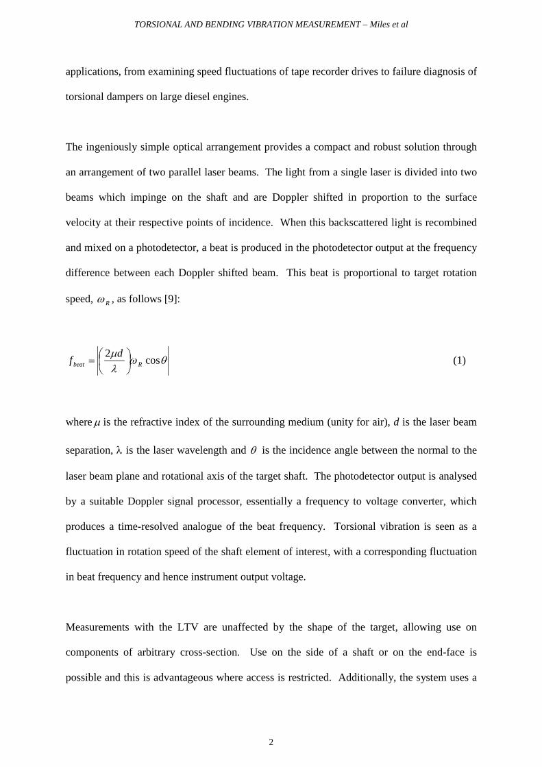
The ingeniously simple optical arrangement provides a compact and robust solution through
an arrangement of two parallel laser beams. The light from a single laser is divided into two
beams which impinge on the shaft and are Doppler shifted in proportion to the surface
velocity at their respective points of incidence. When this backscattered light is recombined
and mixed on a photodetector, a beat is produced in the photodetector output at the frequency
difference between each Doppler shifted beam. This beat is proportional to target rotation
speed, Rω , as follows [9]:
θωλµ cos2
Rbeatdf
= (1)
where µ is the refractive index of the surrounding medium (unity for air), d is the laser beam
separation, λ is the laser wavelength and θ is the incidence angle between the normal to the
laser beam plane and rotational axis of the target shaft. The photodetector output is analysed
by a suitable Doppler signal processor, essentially a frequency to voltage converter, which
produces a time-resolved analogue of the beat frequency. Torsional vibration is seen as a
fluctuation in rotation speed of the shaft element of interest, with a corresponding fluctuation
in beat frequency and hence instrument output voltage.
Measurements with the LTV are unaffected by the shape of the target, allowing use on
components of arbitrary cross-section. Use on the side of a shaft or on the end-face is
possible and this is advantageous where access is restricted. Additionally, the system uses a

TORSIONAL AND BENDING VIBRATION MEASUREMENT – Miles et al
3
minimum of optical components and has straightforward signal processing requirements.
Often retro-reflective tape is applied to the target shaft to facilitate use of a low powered
laser. The LTV has been demonstrated to give good agreement with existing methods of
measuring torsional vibration [9] and its optical arrangement has been adopted in a
commercial instrument [11].
The Doppler shift of a single laser beam incident on a rotating shaft can be related to the
motion of the target in its six degrees of freedom. The unique optical geometry of the LTV
offers immunity to shaft axial or radial motion, such as the cylindrical whirl orbit of Figure
1a, as well as equivalent motion of the instrument itself. This paper examines the
instrument’s measurable sensitivity to angular vibration, an issue which has not been
explicitly addressed in previous work. During such motion, the shaft rotation vector
undergoes a change of direction, effectively changing the incidence angle, θ , and influencing
the measurements. A simple example of this is the conical whirl orbit of Figure 1b. This
motion will subsequently be referred to as angular lateral vibration which also includes
whirling of a flexible shaft. In later discussion of crankshaft motion, this is more specifically
described as bending vibration.
Angular lateral vibration of a rotating shaft is inherently difficult to measure and, as with
torsional vibration, measurement of actual shaft motion must be obtained directly from the
component, often with complicated instrumentation requirements. Previously reported
measurements have used accelerometers attached to a stationary housing which is carried by
a retro-fitted bearing on the shaft of interest [12, 13]. Studies of engine crankshaft vibration
have also included measurements of shaft lateral motion by eddy current displacement
sensors [14] and strain gauges attached to the shaft [15]. In an additional study, closely

TORSIONAL AND BENDING VIBRATION MEASUREMENT – Miles et al
4
related to this one, angular vibration measurements have also been taken from a non-rotating
structure using a novel laser Doppler transducer [16].
Comprehensive theory is presented in this paper to consider, for the first time, the effects of
shaft motion in all degrees of freedom on torsional vibration measurements obtained with an
LTV. Subsequent discussion, based on experimental results, quantifies the sensitivity of the
instrument to angular lateral vibration highlighting when the potential for measurement
ambiguity exists. In the context of the instrument noise floor and typical torsional and
angular lateral vibration levels found in practice, guidelines are then proposed for accurate
assessment of genuine torsional oscillation by optimisation of the optical geometry used. In
this way complete immunity to all lateral shaft vibrations can be achieved.
Ultimately, a solution is proposed which permits unambiguous measurement of shaft
torsional vibration in situations where use of a single LTV would otherwise show
unacceptable sensitivity to angular lateral motion. Measurements from an engine crankshaft
demonstrate the practical application of this new technique. Simultaneously, this technique
can provide a measurement of the bending vibration of a rotating shaft and experimental
results are presented which give an insight into the complex lateral motion of a reciprocating
engine crankshaft.
2. ADVANCES IN THE THEORY OF OPERATION OF THE LTV
2.1. GENERAL DEFINITION OF MOTION OF A POINT ON A ROTATING SHAFT
Consider the general case of a point P on the surface of an arbitrarily shaped shaft, located by
position vector pr with respect to the co-ordinate axes, as illustrated in Figure 2. The main
TORSIONAL AND BENDING VIBRATION MEASUREMENT – Miles et al
5
co-ordinate system OXYZ has its origin fixed on the undeflected shaft rotation axis (i.e. in the
absence of any vibration) which also defines z . The X-, Y- and Z-axes maintain their
directions during vibration.
The instantaneous velocity vector can be related to motion in six degrees-of-freedom,
comprising the three translational motions xV , yV and zV and components related to the
angular motion of the shaft. These are considered as the shaft rotation at angular velocity Rω
about an axis defined by the vector Rz and angular lateral motion which results in the angular
displacement of Rz relative to z . This latter motion is described by finite rotations about the
two co-ordinate axes, X and Y, making use of the unit vectors x and y . These rotations of
the shaft axis are conventionally described as pitch and yaw respectively [17].
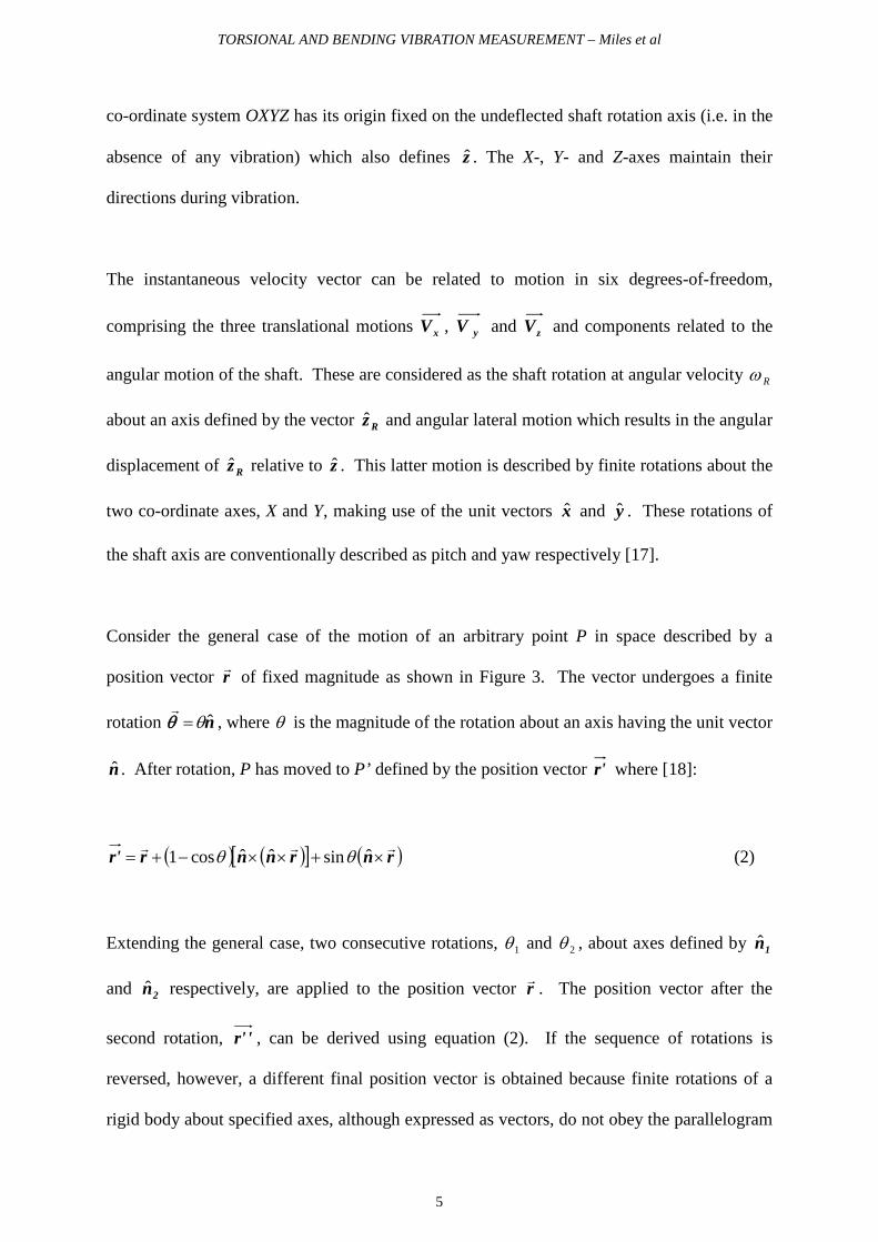
Consider the general case of the motion of an arbitrary point P in space described by a
position vector r of fixed magnitude as shown in Figure 3. The vector undergoes a finite
rotation nθ=θ
, where θ is the magnitude of the rotation about an axis having the unit vector
n . After rotation, P has moved to P’ defined by the position vector r' where [18]:
( ) ( )[ ] ( )rnrnnrr' ×+××−+= ˆsinˆˆcos1 θθ (2)
Extending the general case, two consecutive rotations, 1θ and 2θ , about axes defined by 1n
and 2n respectively, are applied to the position vector r . The position vector after the
second rotation, 'r' , can be derived using equation (2). If the sequence of rotations is
reversed, however, a different final position vector is obtained because finite rotations of a
rigid body about specified axes, although expressed as vectors, do not obey the parallelogram

TORSIONAL AND BENDING VIBRATION MEASUREMENT – Miles et al
6
law of addition unless the two rotations are about a common axis or are infinitesimal.
Assuming infinitesimal rotations the final positions for the two sequences of rotations are
equivalent:
( ) rnnr'r' 21
×++= ˆˆ 21 θθ (3)
The assumption of infinitesimal rotations is valid for typical estimates of shaft angular lateral
vibration magnitudes. Additionally, experimentally it is not appropriate to define an order in
which to consider the rotations of the shaft about the X- and Y-axes. In light of this, the
change in position vector, pr∆ , during time increment t∆ , is derived from equation (3).
Including a third component, zz ˆzθ=θ , described as the roll or spin about the Z-axis and with
a pitch rotation, xx ˆxθ=θ , and a yaw rotation, yy ˆyθ=θ , it is given as:
( ) PP rzyxr ×++=∆ ˆˆˆ zyx θθθ (4)
The velocity components of point P due to these rotations can be determined from the time
derivative of its position vector:
( ) ( ) ( )PPPP rzryrx
r×+×+×== ˆˆˆ zyxP dt
dv θθθ (5)
However, in practice it is not possible to distinguish between the torsional vibration of the
rotating shaft element and the zθ component of angular lateral vibration. To proceed it is
assumed that the motion consists primarily of the rotational velocity, ( )tRω , of the

TORSIONAL AND BENDING VIBRATION MEASUREMENT – Miles et al
7
illuminated element (which includes the torsional vibration of principal interest).
Furthermore, this motion is considered about an axis described by the time-dependent unit
vector Rz rather than the constant unit vector z . The complete velocity of point P can then
be considered as the sum of four terms:
( ) ( ) ( ) ( )PRPPzyxP rzryrxVVVV ×+×+×+++= ˆˆˆ Ryx ωθθ (6)
The first term is the sum of the three components of translation. The second and third terms
describe the dependence on angular lateral motion about X- and Y-axes, independent of the
shaft rotation. In the fourth term, the influence of the main shaft rotation, including the
torsional vibration of primary interest, is clear while the time-dependence of Rz indicates the
second effect of angular lateral vibration, in this case obviously dependent on shaft rotation.
2.2. DERIVATION OF LTV OUTPUT
The optical configuration of the LTV to be used in this theoretical development is shown in
Figure 4. The original laser beam has been split into two parallel beams by a beam-splitter
and mirror and the beams are incident on a shaft of arbitrary cross-section. The shaft is
rotating at angular frequency ),(tRω about the axis defined by ( )tRz . (In subsequent
manipulations, Rω and Rz are used for brevity). The two equal intensity beams are of
perpendicular separation d and impinge on the shaft surface at arbitrary points A and B,
described by position vectors Ar and Br . These beams are collected in direct backscatter in
the direction defined by the unit vector i . The shaft rotation axis is free to undergo changes
of direction but Rz is assumed to be identical at each of the incidence points A and B. In fact,
the analysis assumes Rz to be constant from the co-ordinate system origin, O, to the furthest

TORSIONAL AND BENDING VIBRATION MEASUREMENT – Miles et al
8
illuminated shaft cross-section but the instrument’s immunity to translational motion makes
the choice of the position of the origin an arbitrary one. Without any loss of generality, one
possibility is, therefore, to place O in one of the illuminated cross-sections which makes the
requirement for constant Rz between incidence points A and B a reasonable condition.
The incidence angles defining the relative position of the instrument and target shaft are
resolved into two orthogonal planes, as shown in Figure 5. Considering them separately, α is
the included angle between i and z while β is the included angle between the plane formed
by the two incident laser beams and the plane of the cross-section of the shaft, perpendicular
to the undeflected rotation axis. In the ‘ideal’ instrument set-up the plane of the LTV beams
is parallel to the shaft cross-section, i.e. α = 90° and β = 0°. The X-axis of the fixed co-
ordinate system is thus defined as parallel to and in the direction of the laser beam backscatter
vector i for this special case. For the general set-up detailed in Figure 6, the plane of the
laser beams has undergone a rotation about the X-axis, changing β, followed by a rotation
about the Y-axis, changing α.
Each of the laser beams undergoes a Doppler shift when scattered by the moving shaft
surface. The beams collected in direct backscatter from points A and B have undergone
Doppler shifts Af and Bf where [6]:
( ) BA,Vi .ˆ /2, λ=BAf (7)
The output from the detector is modulated at the beat frequency:
TORSIONAL AND BENDING VIBRATION MEASUREMENT – Miles et al
9
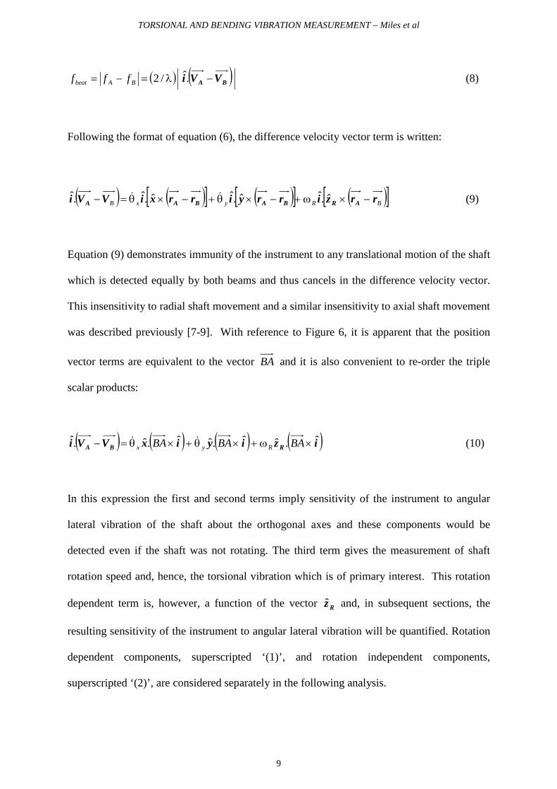
( ) ( ) . /2 BA VVi −λ=−= BAbeat fff (8)
Following the format of equation (6), the difference velocity vector term is written:
( ) ( )[ ] ( )[ ] ( )[ ]BRyxB rrzirryirrxiVVi ARBABAA −×ω+−×θ+−×θ=− ˆ.ˆˆ.ˆˆ.ˆ.ˆ.
(9)
Equation (9) demonstrates immunity of the instrument to any translational motion of the shaft
which is detected equally by both beams and thus cancels in the difference velocity vector.
This insensitivity to radial shaft movement and a similar insensitivity to axial shaft movement
was described previously [7-9]. With reference to Figure 6, it is apparent that the position
vector terms are equivalent to the vector BA and it is also convenient to re-order the triple
scalar products:
( ) ( ) ( ) ( )iziyixVVi RBAˆ.ˆˆ.ˆˆ.ˆ.ˆ ×ω+×θ+×θ=− BABABA Ryx
(10)
In this expression the first and second terms imply sensitivity of the instrument to angular
lateral vibration of the shaft about the orthogonal axes and these components would be
detected even if the shaft was not rotating. The third term gives the measurement of shaft
rotation speed and, hence, the torsional vibration which is of primary interest. This rotation
dependent term is, however, a function of the vector Rz and, in subsequent sections, the
resulting sensitivity of the instrument to angular lateral vibration will be quantified. Rotation
dependent components, superscripted ‘(1)’, and rotation independent components,
superscripted ‘(2)’, are considered separately in the following analysis.

TORSIONAL AND BENDING VIBRATION MEASUREMENT – Miles et al
10
The vector product ( )i×BA is obviously important but the shape dependency inherent in BA
is inconvenient. On expansion:
( ) ( )sii ˆ2/sinˆˆ πδ +=× BABA (11)
where s is a unit vector perpendicular to both BA and i with ( )2/πδ + as their included
angle, as shown in Figure 6. It can be seen from the figure that the perpendicular beam
separation, d, is equal to δcosBA and it is also convenient to define a unit vector sid ˆˆˆ ×=
which is in the direction of a perpendicular line joining the parallel beams as shown in Figure
6. Incorporating these terms allows equation (11) to be re-written as:
( ) idsi ˆˆˆˆ ×==× ddBA (12)
Equation (12) clearly demonstrates that the dependence on BA , i.e. the shape sensitivity, has
been lost allowing the parallel beam arrangement to be used on a shaft of arbitrary cross-
section without consequence. Using equation (12), the rotation dependent term from
equation (10) can be written in forms that will both be useful for further manipulation as:
( )( ) ( ) ( )RRA zidszVVi ˆˆ.ˆˆ.ˆ.ˆ1
×ω=ω=− dd RRB (13)
The time-varying shaft rotation vector Rz can be expressed as the sum of a constant unit
vector z and a fluctuating component z∆ related to the angular lateral vibration and this can

TORSIONAL AND BENDING VIBRATION MEASUREMENT – Miles et al
11
be used to expand the scalar product in equation (13). It is easy to consider the constant
component:
( ) αβ sincosˆ.ˆ −=sz (14)
but it is useful to express the time-dependent component, z∆ , as the combination of two
infinitesimal rotations first:
( ) ( )yxz ˆˆ xy θθ −=∆ (15)
Combining equations (13) and (15), the variable part equivalent to the scalar product of
equation (14) is:
( ) ( ) ( )( )[ ] ( ) ( )βθ−+βαθ=θ−×+θ×= sincoscosˆˆˆˆ.ˆˆ. xyxy yixidsz∆ (16)
Combining equations (13), (14) and (16), the following expression highlights the rotation
speed dependent sensitivity of the LTV to angular lateral vibration of the shaft:
( )( ) ( ) ( ) ( )[ ]βθβαθαβω sincoscossincos.ˆ1
xyRB d −++−=−VVi A (17)
Using equation (12) and evaluating the vector products, the rotation independent part of
equation (10) is given by:
( )( ) [ ]βθ+αβθ=− sincoscos.ˆ2
yxd BA VVi (18)

TORSIONAL AND BENDING VIBRATION MEASUREMENT – Miles et al
12
The resultant beat frequency is finally obtained by substitution of equations (17) and (18) into
equation (8). With time-dependent notation again:
( ) ( ) ( )( ) ( )( )[ ]( )( ) ( )( )[ ] sincoscos
sincoscossincos2
βθαβθ
βθβαθαβωλ
ttd
ttdtf
yx
xyRbeat
++
−++−= (19)
This demonstrates the sensitivity of the LTV to all angular motions of the shaft and
particularly how the sensitivity to angular lateral vibration depends significantly on the LTV
incidence angles, α and β .
It can be seen from equation (19) that the main factors over which the operator has control in
determining the mean beat frequency are the laser beam separation, d, and the incidence
angles, α and β . Practical limits to the usable range of α and β are determined by the
scattering of sufficient light from the target shaft and the minimum value of beatf which can
be demodulated. For one commercial version of the instrument the following angular ranges
are quoted when using retro-reflective tape [19]. For side of shaft measurements, a minimum
α of 35° (limited by scattered light intensity) is recommended. For end of shaft
measurements a minimum α should be between 30° (limited by beatf value) and 55° (limited
by scattered light intensity). Experimentation during this study found similar practical limits
and these have been added to figure 9 which will be discussed later. The sensitivity to angular
lateral vibration reported in this paper, however, indicates the undesirability of using the
instrument at, or even close to, these extremes. Values of β up to 75° are considered
acceptable in reducing the effective beam separation which may be necessary, for example,
on small diameter shafts, but operation with 0≠β is generally unusual.
TORSIONAL AND BENDING VIBRATION MEASUREMENT – Miles et al
13
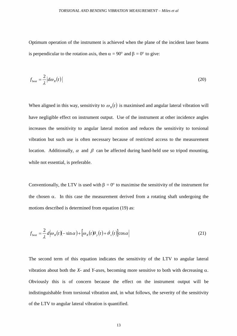
Optimum operation of the instrument is achieved when the plane of the incident laser beams
is perpendicular to the rotation axis, then α = 90° and β = 0° to give:
( ) 2 tdf Rbeat ωλ
= (20)
When aligned in this way, sensitivity to ( )tRω is maximised and angular lateral vibration will
have negligible effect on instrument output. Use of the instrument at other incidence angles
increases the sensitivity to angular lateral motion and reduces the sensitivity to torsional
vibration but such use is often necessary because of restricted access to the measurement
location. Additionally, α and β can be affected during hand-held use so tripod mounting,
while not essential, is preferable.
Conventionally, the LTV is used with β = 0° to maximise the sensitivity of the instrument for
the chosen α. In this case the measurement derived from a rotating shaft undergoing the
motions described is determined from equation (19) as:
( )( ) ( ) ( ) ( )[ ] αθθωαωλ
cossin2 ttttdf xyRRbeat++−= (21)
The second term of this equation indicates the sensitivity of the LTV to angular lateral
vibration about both the X- and Y-axes, becoming more sensitive to both with decreasing α.
Obviously this is of concern because the effect on the instrument output will be
indistinguishable from torsional vibration and, in what follows, the severity of the sensitivity
of the LTV to angular lateral vibration is quantified.

TORSIONAL AND BENDING VIBRATION MEASUREMENT – Miles et al
14
2.3. EXPERIMENTAL VALIDATION
For experimental validation of equation (19) an experimental rig, shown in figure 7, was
designed to simulate angular lateral vibration of a rotating shaft. A dynamic shaker was used
to drive a section of gear rack in a linear direction. The rack meshed with a large diameter
gear, which rotated back and forth to provide the required angular lateral motion about either
the X- or Y-axis, depending on the relative alignment of the rig and LTV. A small d.c. motor
carrying the target shaft was mounted on top of the gear. An a.c. modulation could be added
to the d.c. motor drive causing the motor speed to fluctuate, thereby simulating a torsional
vibration. The amplitude and frequency of the simulated vibrations and the shaft rotational
speed were all independently controllable.
In initial qualitative tests, the LTV was seen to be sensitive to both yθ and xθ motions with
the magnitude of the former component proportional to mean rotation speed and that of the
latter not, as predicted by equation (21). For full quantitative analysis, simulation of yθ and
xθ motions simultaneously is necessary but this would require a substantially more
complicated experimental rig. Simulation of angular lateral motion around one axis is
considered sufficient for the validation required here and this has been reported previously
[20, 21].
To illustrate the sensitivity to angular lateral vibration quantitatively, the LTV was arranged
at α = 45°, incident on the side of the shaft. This angle was chosen as a satisfactory
compromise of three factors: sensitivity to torsional vibration, sensitivity to angular lateral
vibration and to ensure sufficient intensity of light collected. The experimental rig was used
to simulate torsional and angular lateral vibration of the shaft. Figure 8 shows the spectrum
TORSIONAL AND BENDING VIBRATION MEASUREMENT – Miles et al
15
of the LTV signal in which combination of the simulated components at, nominally, 25Hz
(bending vibration) and 45Hz (torsional vibration) is apparent, indicating that it is not
possible to distinguish between the motions with this measurement. Guidelines for use of the
LTV will now be described before resolution of the combined effects of torsional and
bending vibration is offered as further validation of the predicted LTV behaviour.
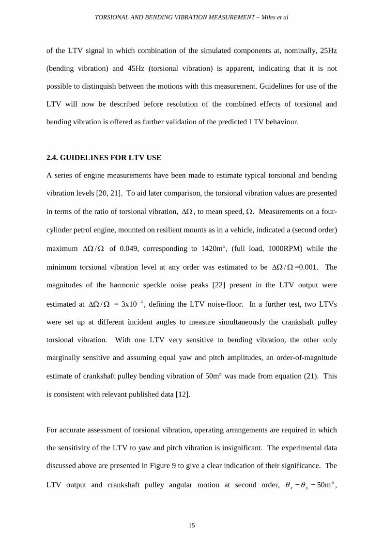
2.4. GUIDELINES FOR LTV USE
A series of engine measurements have been made to estimate typical torsional and bending
vibration levels [20, 21]. To aid later comparison, the torsional vibration values are presented
in terms of the ratio of torsional vibration, ∆Ω , to mean speed, Ω. Measurements on a four-
cylinder petrol engine, mounted on resilient mounts as in a vehicle, indicated a (second order)
maximum Ω∆Ω / of 0.049, corresponding to 1420m°, (full load, 1000RPM) while the
minimum torsional vibration level at any order was estimated to be Ω∆Ω / =0.001. The
magnitudes of the harmonic speckle noise peaks [22] present in the LTV output were
estimated at Ω∆Ω / = 3x10 4− , defining the LTV noise-floor. In a further test, two LTVs
were set up at different incident angles to measure simultaneously the crankshaft pulley
torsional vibration. With one LTV very sensitive to bending vibration, the other only
marginally sensitive and assuming equal yaw and pitch amplitudes, an order-of-magnitude
estimate of crankshaft pulley bending vibration of 50m° was made from equation (21). This
is consistent with relevant published data [12].
For accurate assessment of torsional vibration, operating arrangements are required in which
the sensitivity of the LTV to yaw and pitch vibration is insignificant. The experimental data
discussed above are presented in Figure 9 to give a clear indication of their significance. The
LTV output and crankshaft pulley angular motion at second order, oyx m50==θθ ,

TORSIONAL AND BENDING VIBRATION MEASUREMENT – Miles et al
16
estimated from the simultaneous LTV measurements, can be used to define operating limits
for use of the LTV on any shaft experiencing such levels of angular lateral vibration. To
allow direct comparison of results, the beat frequency resulting when a steadily rotating shaft
undergoes angular lateral vibration is considered to be equivalent to that resulting from a
shaft element rotating at a mean speed Ω with a torsional vibration ∆Ω . Comparison can
therefore be made between the relative magnitudes of angular lateral vibration induced
components, genuine torsional vibration and the LTV noise floor, highlighting incidence
angles where the sensitivity to angular lateral vibration becomes of concern in this typical
application.
It is apparent from Figure 9 that for α<70° the magnitude of signal components induced by
angular lateral vibration is potentially significant and it is recommended that use of the LTV
in this incidence angle range is avoided. In the range 70° < α < 80° the error components are
of measurable magnitude and caution should be exercised in the interpretation of data.
Finally, for 80° < α ≤ 90° error components were similar to or smaller than the instrument
noise floor and operation of the LTV is effectively immune to all lateral vibration, allowing
reliable and accurate measurement of torsional vibration. The same considerations apply to
hand-held operation of the LTV because human body movement may induce significant
changes in the instrument output in the same way as angular lateral vibration.
3. MEASUREMENT OF PURE TORSIONAL VIBRATION AND ASSESSMENT OF
BENDING VIBRATION
3.1. PROCESSING OF LTV OUTPUTS

TORSIONAL AND BENDING VIBRATION MEASUREMENT – Miles et al
17
Experience in torsional vibration measurement has shown that while it is common to align an
LTV with incidence angle β = 0°, restricted access often demands use with α for which there
is some measurable sensitivity to angular lateral vibrations. It is proposed that with the use of
two suitably aligned LTVs, a measure of pure torsional vibration can be derived in situations
where a single LTV measurement would leave ambiguity. Simultaneously this technique can
give an assessment of the shaft bending vibration [23], a measurement not previously realised
by non-contact means. Up to this point the general term angular lateral vibration has been
used to describe the angular displacement of a rotating shaft, as this can result from motion of
the whole machine or relative motion of the rotating shaft within the machine. The angular
lateral vibrations in the engine measurements to follow will, for example, include the whole
engine rocking on its mountings as well as crankshaft bending. However, the term bending
vibration will now be used to describe the yaw and pitch motions, particularly with respect to
engine crankshafts.
In this new configuration two LTVs are arranged symmetrically at equal and opposite
incidence angles as shown in Figure 10, on either the side (Arrangement A) or end face
(Arrangement B) of the shaft. With β = 0° in both cases, the sensitivity to bending vibrations
is described by equation (21). Figure 11 shows that with a nominally specified incidence
angle α there are four possible arrangements. (The LTV outputs for positions 1 and 4 on the
side of the shaft are equivalent to that from positions 1’ and 4’ on the end face of the shaft,
the only differences resulting from illumination of a different shaft cross-section). Following
the right-hand convention, the four positions are respectively; +α, ( )απ − , ( )απ + and -α.
Substituting these angles into equation (21) the following expressions are derived:

TORSIONAL AND BENDING VIBRATION MEASUREMENT – Miles et al
18
( ) ( ) ( ) ( )[ ] αθθωαωλ
cossin231 ttttdff xyRR
+−== (22a)
( ) ( ) ( ) ( )[ ] αθθωαωλ
cossin242 ttttdff xyRR
++== (22b)
Qualitative experimental investigation confirmed that torsional vibration components were
in-phase with each other for all four positions of the LTVs. Referring to Figure 11, the LTV
signal components due to ( )tyθ motion (magnitude proportional to rotation speed), relative to
position 1, were in-phase at position 3 and out-of-phase at positions 2 and 4, as predicted by
equations (22a&b). Further preliminary tests confirmed the sensitivity of the LTV to ( )txθ
motion (components independent of rotation speed) with the same relative phase
relationships as for the ( )tyθ sensitivity.
The proportionality constant for the LTV at position 1, K 1 , incorporates the geometrical and
optical constants of the arrangement together with the demodulator constant ek1 . Therefore
the voltage output from this LTV can be written as follows, with similar expressions for the
other positions:
( ) ( ) ( ) ( )
+−=
αθθω
ωtan11
ttttKV xyR
R
(23a)
where:
αλ
sin211 dkK e= (23b)

TORSIONAL AND BENDING VIBRATION MEASUREMENT – Miles et al
19
If simultaneous measurements are taken with two LTVs at positions 1 (or 3) and 2 (or 4), the
sum of the outputs provides a measurement of ( )tRω :
( )tKV
KV
Rω22
2
1
1 =+ (24)
The mean value of this quantity is proportional to the mean rotation speed and the fluctuating
component provides the totally unambiguous measure of torsional vibration velocity, immune
to all translational and angular lateral shaft vibrations. This arrangement therefore provides a
reliable means to achieve accurate measurement of pure torsional vibration from a laterally
vibrating shaft where restricted optical access precludes the use of a single LTV with 80° < α
≤ 90°.
The difference in the outputs gives the following signal:
( ) ( ) ( )[ ]tttKV
KV
xyR θθωα
+=−tan
2
2
2
1
1 (25a)
A normalised quantity, derived by combination with equation (24), has also been useful:
( ) ( )( )
+=
+
−
tt
tKV
KV
KV
KV
R
xy ω
θθ
α
tan1
2
2
1
1
2
2
1
1 (25b)
These equations suggest the possibility for simultaneous measurement of the bending
vibration of a rotating shaft, a notoriously difficult measurement. However, in this case it is
TORSIONAL AND BENDING VIBRATION MEASUREMENT – Miles et al
20
not possible to add or subtract signals to give a quantity that is purely dependent on only one
of the orthogonal motions, ( )txθ or ( )tyθ . A measurement obtained in the manner of
equation (25a) or (25b) will have sensitivity to both yaw and pitch, with the magnitude of the
resultant signal dependent on the relative phase between the components and their individual
amplitudes. In some circumstances it may be possible, however, to make a reasonable
estimate of the motion and such a case is made at the end of section 3.3
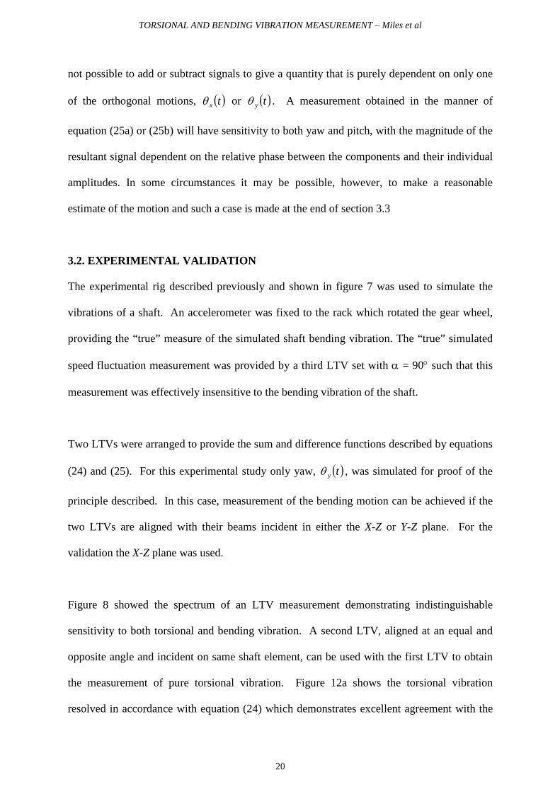
3.2. EXPERIMENTAL VALIDATION
The experimental rig described previously and shown in figure 7 was used to simulate the
vibrations of a shaft. An accelerometer was fixed to the rack which rotated the gear wheel,
providing the “true” measure of the simulated shaft bending vibration. The “true” simulated
speed fluctuation measurement was provided by a third LTV set with α = 90° such that this
measurement was effectively insensitive to the bending vibration of the shaft.
Two LTVs were arranged to provide the sum and difference functions described by equations
(24) and (25). For this experimental study only yaw, ( )tyθ , was simulated for proof of the
principle described. In this case, measurement of the bending motion can be achieved if the
two LTVs are aligned with their beams incident in either the X-Z or Y-Z plane. For the
validation the X-Z plane was used.
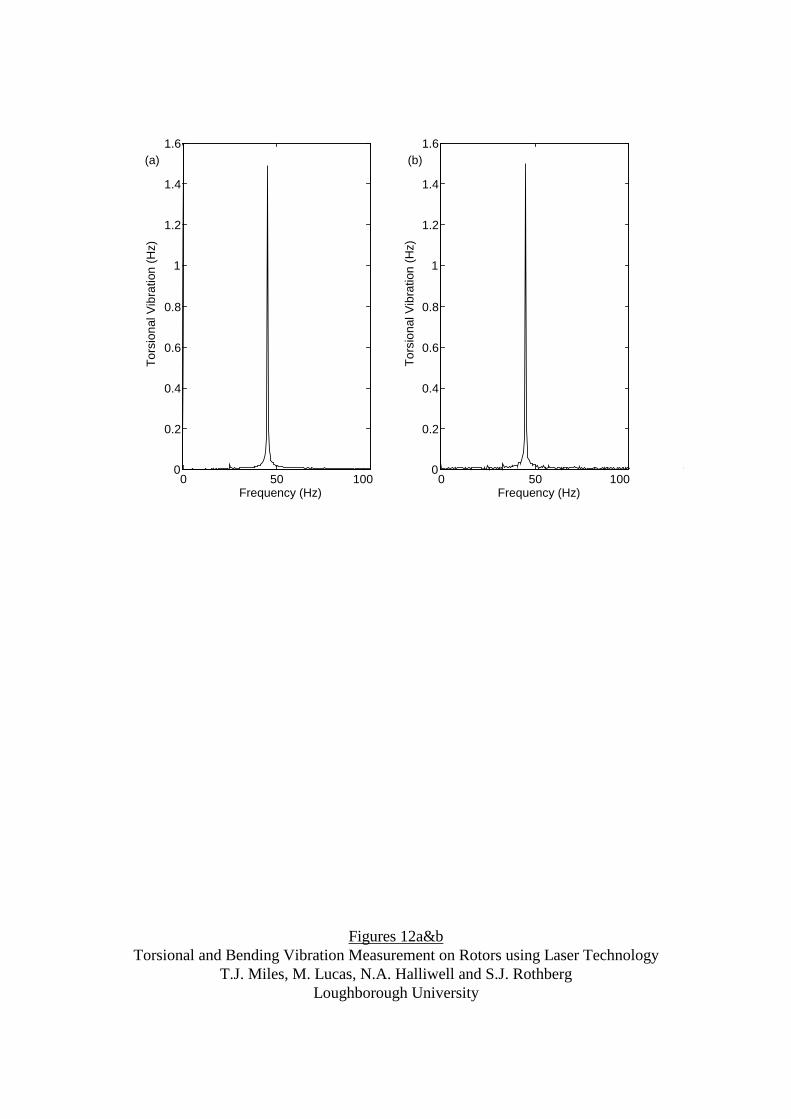
Figure 8 showed the spectrum of an LTV measurement demonstrating indistinguishable
sensitivity to both torsional and bending vibration. A second LTV, aligned at an equal and
opposite angle and incident on same shaft element, can be used with the first LTV to obtain
the measurement of pure torsional vibration. Figure 12a shows the torsional vibration
resolved in accordance with equation (24) which demonstrates excellent agreement with the
TORSIONAL AND BENDING VIBRATION MEASUREMENT – Miles et al
21
“true” measurement in Figure 12b. This technique therefore provides a measure of pure
torsional vibration in situations where measurement with a single LTV would be ambiguous
due to sensitivity to shaft bending vibration.
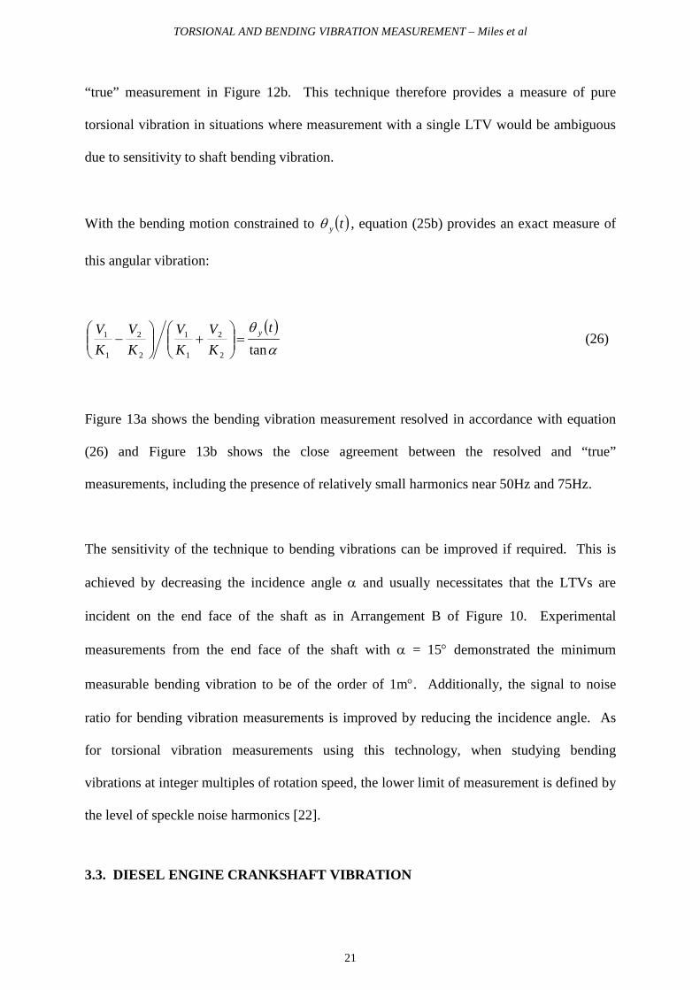
With the bending motion constrained to ( )tyθ , equation (25b) provides an exact measure of
this angular vibration:
( )α
θtan2
2
1
1
2
2
1
1 tKV
KV
KV
KV y=
+
− (26)
Figure 13a shows the bending vibration measurement resolved in accordance with equation
(26) and Figure 13b shows the close agreement between the resolved and “true”
measurements, including the presence of relatively small harmonics near 50Hz and 75Hz.
The sensitivity of the technique to bending vibrations can be improved if required. This is
achieved by decreasing the incidence angle α and usually necessitates that the LTVs are
incident on the end face of the shaft as in Arrangement B of Figure 10. Experimental
measurements from the end face of the shaft with α = 15° demonstrated the minimum
measurable bending vibration to be of the order of 1m°. Additionally, the signal to noise
ratio for bending vibration measurements is improved by reducing the incidence angle. As
for torsional vibration measurements using this technology, when studying bending
vibrations at integer multiples of rotation speed, the lower limit of measurement is defined by
the level of speckle noise harmonics [22].
3.3. DIESEL ENGINE CRANKSHAFT VIBRATION

TORSIONAL AND BENDING VIBRATION MEASUREMENT – Miles et al
22
A loaded 2.0 litre diesel engine was used as a first practical example to demonstrate the
measurement of pure torsional vibration with estimation of crankshaft bending vibration.
Two LTVs were arranged symmetrically at approximately α = 35° on the end face of the
crankshaft pulley. With this alignment measurement by a single instrument would be
contaminated by bending vibration. A third LTV was set up at α = 75° (limited by access),
an arrangement virtually insensitive to shaft bending vibration, to provide the “true” measure
of torsional vibration for comparison. The first two LTV outputs were recorded
simultaneously and processed to give the resolved torsional and bending vibration
measurements. (Some differences between the measurements may be attributed to the fact
that it was not possible to obtain the results from all three LTVs simultaneously).
Figure 14 shows a typical torsional vibration signal measured on the engine at 750rpm, from
a single LTV at α = 35°. At this rotation speed the 2nd order crankshaft torsional vibration
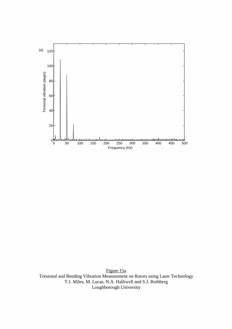
dominates the response. Figures 15a-c show the torsional vibration spectra from a single
LTV at α = 35°, from the “true” measurement and from the resolved signal respectively. The
main orders of torsional vibration, namely, 2nd, 4th and 6th, are clearly evident in each case
and comparison of these spectra highlights important differences.
Firstly, it is apparent that the magnitudes of the resolved measurement components are closer
to the “true” measurement than those of the single LTV. In addition, the response in the
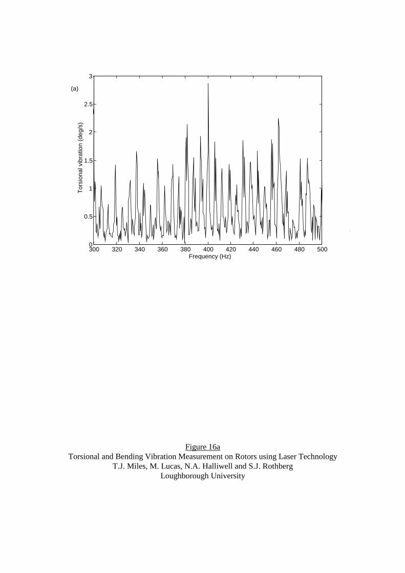
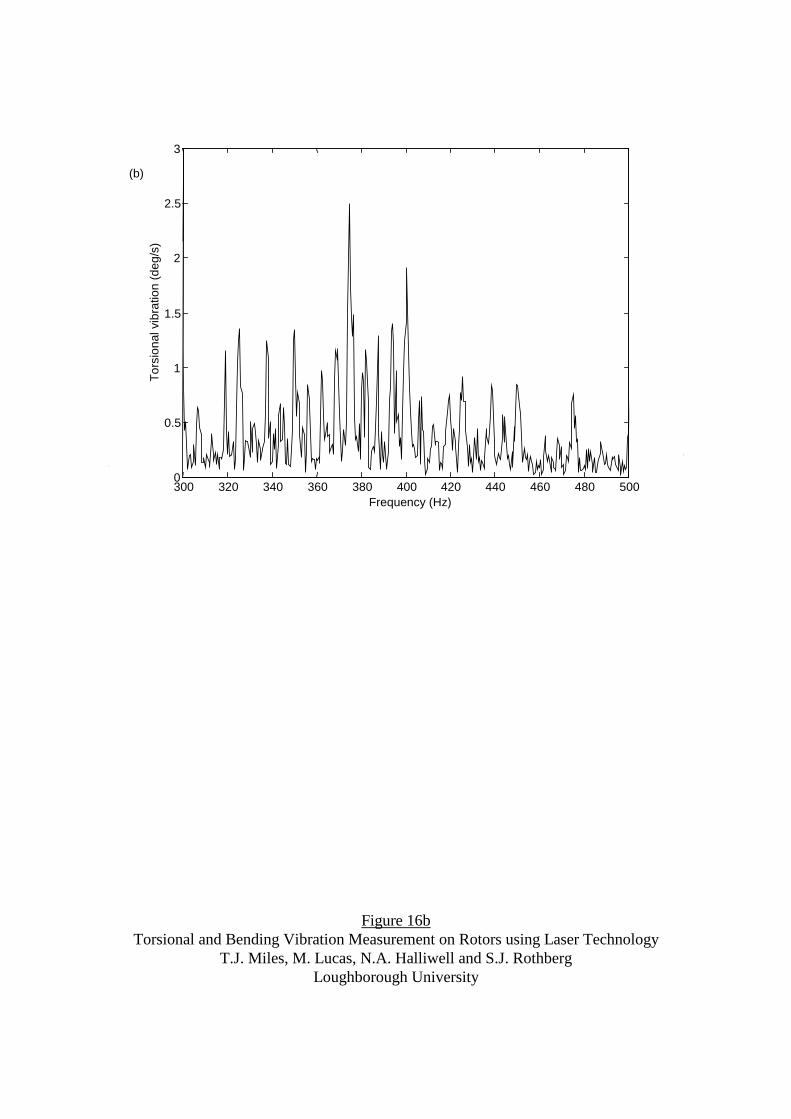
frequency range 300Hz to 500Hz is quite different between the resolved signal and that from
the single LTV. This section of the spectrum has been expanded in Figures 16a&b for the
single LTV and resolved measurement respectively. The spectra are significantly different
and it will be shown shortly how this is due to the substantial contribution of bending
vibration in the single LTV measurement. The resolved measurement has a clear peak at

TORSIONAL AND BENDING VIBRATION MEASUREMENT – Miles et al
23
375Hz at which there is known to be a torsional mode of the crankshaft. This mode cannot
be distinguished in Figure 16a in which a large peak at 400Hz appears to dominate.
Comparison of the figures highlights the technique’s importance for accurate assessment of
torsional vibration.
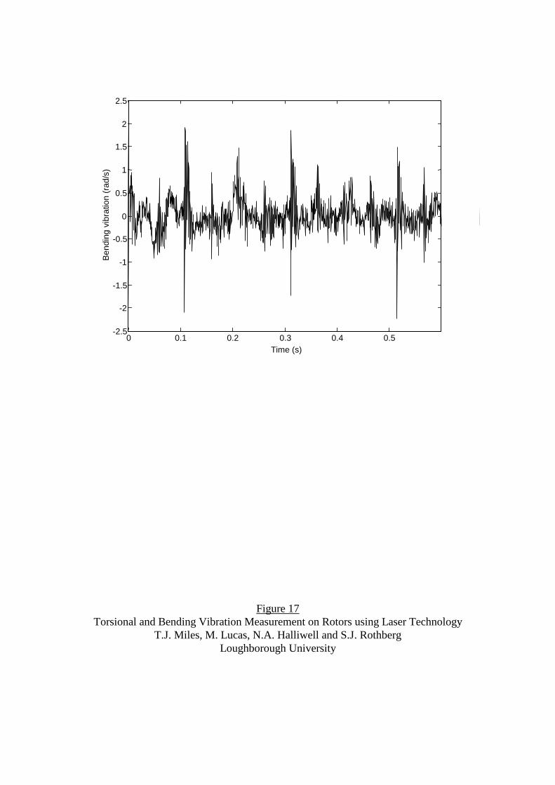
Using equation (25b), the crankshaft bending vibration is shown in Figure 17, differing
significantly, but in the manner expected, from the torsional vibration signal of Figure 14.
The repeating pattern of impacts from the firing of the four cylinders is clear and occurs over
a two revolution time period as expected for a four-stroke engine. The largest impact is that
of cylinder 1, closest to the pulley position, consistent with previous experimental studies of
crankshaft behaviour [13, 14, 24]. Minor variations between impact sequences occur as a
result of combustion cyclic variability. However, as discussed previously, this measurement
is sensitive to both yaw and pitch motions and resolution of individual motions is not yet
possible.
The spectrum of this motion is shown in Figure 18 with significant differences from the
shape of the torsional vibration spectrum in Figure 15c, as expected. In addition to the
distinct bending vibration peaks occurring at the first four orders of rotation, the spectrum
shows a large vibration response in the 350-500Hz range, which was seen previously to
corrupt the measurement from the single LTV at α = 35°. It is proposed that the broad peak
centred at 455Hz is the first bending mode of the crankshaft, excited by the impacts of the
cylinders firing. Although analytical modelling of crankshaft response has been
comprehensive, previous experimental measurements of crankshaft bending on a rotating
engine have been limited due to a lack of suitable measurement techniques. However,
comparable values of crankshaft bending mode frequencies have been reported for similarly
TORSIONAL AND BENDING VIBRATION MEASUREMENT – Miles et al
24
sized engines [13, 24]. In basic modal analysis of the stationary engine crankshaft, the
natural frequency of the crankshaft in bending was found to be in the range 456-476Hz,
depending on the angular position of the crankshaft and con-rods. Results recorded for five
speeds of the engine under load showed a similar response in the 350-500Hz range with
similar signal magnitude. The dominant peak at 400Hz in figure 16a, described earlier,
seems, therefore, to be due to a combination of torsional and bending motions and may not,
itself, be a particularly significant vibration component.
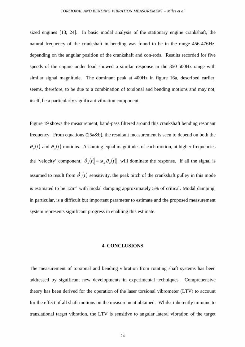
Figure 19 shows the measurement, band-pass filtered around this crankshaft bending resonant
frequency. From equations (25a&b), the resultant measurement is seen to depend on both the
( )tyθ and ( )txθ motions. Assuming equal magnitudes of each motion, at higher frequencies
the ‘velocity’ component, ( ) ( )tt xxx θωθ = , will dominate the response. If all the signal is
assumed to result from ( )txθ sensitivity, the peak pitch of the crankshaft pulley in this mode
is estimated to be 12m° with modal damping approximately 5% of critical. Modal damping,
in particular, is a difficult but important parameter to estimate and the proposed measurement
system represents significant progress in enabling this estimate.
4. CONCLUSIONS
The measurement of torsional and bending vibration from rotating shaft systems has been
addressed by significant new developments in experimental techniques. Comprehensive
theory has been derived for the operation of the laser torsional vibrometer (LTV) to account
for the effect of all shaft motions on the measurement obtained. Whilst inherently immune to
translational target vibration, the LTV is sensitive to angular lateral vibration of the target

TORSIONAL AND BENDING VIBRATION MEASUREMENT – Miles et al
25
shaft which contributes to the measurement derived and is indistinguishable from the
intended measurement of torsional vibration. The effect is dependent on the incidence angle
of the LTV relative to the shaft, becoming more severe as the instrument is moved away from
the optimum arrangement, as is often required by access restriction. The predicted sensitivity
of the instrument to angular lateral motion was confirmed experimentally, clearly
demonstrating the potential for ambiguity in a measurement from a single LTV. Guidelines
were specified to ensure effective immunity to all lateral motion in a typical engine
application.
It was recommended that use of the instrument with the incidence angle α<70° is avoided,
while in the range 80°<α≤90° error components were similar to or smaller than the
instrument noise floor and operation is effectively immune to angular lateral motion.
Emphasis was given to the desirability of using the LTV with 90≈α .
For situations where optimum alignment is not possible, a new and reliable technique was
introduced which provides an accurate measure of pure torsional vibration in situations where
a single LTV demonstrates unacceptable sensitivity to angular lateral vibrations. Two
symmetrically aligned LTVs are used, with the measurement of pure torsional vibration
derived from addition of their output signals. Simultaneously this technique can provide non-
contact assessment of angular lateral, or bending, vibration directly from a rotating
component.
In a diesel engine application, comparison of the genuine torsional vibration with that
measured from a single LTV identified discrepancies due to the effects of shaft bending
vibration. Furthermore, the bending vibration signal gave a clear indication of the shaft

TORSIONAL AND BENDING VIBRATION MEASUREMENT – Miles et al
26
motion due to the combustion impacts. From the spectrum of this measurement it was
possible to locate the natural frequency of the crankshaft in bending, excited by the firing
impulses, and this was confirmed in further modal analysis tests on the engine. During
operation, the magnitude of the bending motion of the crankshaft pulley and the damping for
this mode could be estimated.
However, obtaining the bending vibration measurement from the difference of two LTV
measurements, in the manner described, is sensitive to angular lateral shaft motion about both
the X- and Y-axis. A possible, partial solution to this problem is to take two such
measurements simultaneously, with alignment of one LTV pair around the X-axis as in this
paper and the second pair equivalently around the Y-axis, resolving the pitch and yaw by
mathematical means. This could be done in a similar manner to that described for
measurement of the radial vibration of a rotating shaft with the use of translational laser
vibrometers [25] where similar cross-sensitivity problems exist.
These developments in laser vibrometry for non-contact measurements of shaft vibration will
allow a much greater depth of study to be realised in the design and development of rotating
machinery. The assessment of shaft bending vibration, in particular, is a further step forward
in the application of laser vibrometry to rotating machinery diagnostics.
REFERENCES
1 R.L. SMITH 1992 Sound and Vibration 26 (September) 22-24. Torsional vibration.

TORSIONAL AND BENDING VIBRATION MEASUREMENT – Miles et al
27
2 R.N. BROWN 1960 Transactions of the ASME: Journal of Engineering for Power 82
215-220. A torsional vibration problem as associated with synchronous motor driven
machines.
3 J.M. VANCE 1988 Rotordynamics of Turbomachinery. New York: John Wiley &
Sons.
4 K. FUJII 1991 Proceedings of the 6th International Pacific Conference on Automotive
Engineering Seoul, South Korea. 357-363. SAE Paper 912495. A simulation of crankshaft
bending vibration.
5 T. KAMIYA, T. ATSUMI and K. TASAKA 1988 SAE Transactions 97(4) 4.59-4.65.
SAE Paper 880078. Toyota’s new type of crankshaft pulley to improve the compartment
tone quality.
6 L.E. DRAIN 1980 The Laser Doppler Technique Ch.9. Chichester: John Wiley &
Sons.
7 N.A. HALLIWELL. C.J.D. PICKERING and P.G. EASTWOOD 1984 Journal of
Sound and Vibration 93(4) 588-592. The laser torsional vibrometer: a new instrument.
8 N.A. HALLIWELL and P.G. EASTWOOD 1985 Journal of Sound and Vibration
101(3) 466-499. The laser torsional vibrometer.
9 N.A. HALLIWELL 1996 Journal of Sound and Vibration 190(3) 399-418. The laser
torsional vibrometer: a step forward in rotating machinery diagnostics.
10 J.M. VANCE and R.S. FRENCH 1986 Transaction of the ASME Journal of
Mechanisms, Transmission and Automation in Design 180 565-577 Measurement of
Torsional Vibration in Rotating Machinery.
11. BRÜEL & KJÆR (N.A. Halliwell, S.J. Rothberg, T.J. Miles, P.G. Eastwood, C.J.D.
Pickering and K. Gatzwiller) 1994 On the Working Principle of Torsional Vibration Meter
Type 2523: Application Note. Denmark.

TORSIONAL AND BENDING VIBRATION MEASUREMENT – Miles et al
28
12 M.F. ALBRIGHT and D.F. STAFFELD Proceedings of the 1991 Noise and Vibration
Conference Transverse City, USA. Society of Automotive Engineers P-244, 291-305. SAE
Paper 911073. Noise and vibration refinement of the Ford 3.8 litre powertrain.
13 M.KINOSHITA, T. SAKAMOTO and H.OKAMURA 1989 SAE Transactions 98(3)
1605-1615. SAE Paper 891127. An experimental study of a torsional/bending damper
pulley for an engine crankshaft.
14 O. KURODA and Y. FUJII 1988 SAE Transactions 97(4) 4.73-4.82. SAE Paper
880083. An approach to improve engine sound quality.
15 Y-S. PARK, J-Y PARK and C-W LEE 1986 SAE Transaction 95(1) 1.1157-1165.
SAE Paper 860232. Dynamic torsional and bending stress measurement from operating
crankshaft.
16 N.A. HALLIWELL, A. HOCKNELL and S.J. ROTHBERG, 1997, Journal of Sound
and Vibration, 208(3), 1997, 497-500. On the Measurement of Angular Vibration
Displacements: A Laser Tiltmeter.
17 R.A. COLLACOTT 1979 Vibration Monitoring and Diagnosis Ch. 2. London:
George Goodwin.
18 J.H. WILLIAMS 1996 Fundamentals of Applied Dynamics. New York: John Wiley
& Sons.
19 BRÜEL & KJÆR 1992 Torsional Vibration Meter Type 2523 – Instruction Manual.
Denmark.
20 T.J. MILES, M. LUCAS and S.J. ROTHBERG 1995 Proceedings of the 15th ASME
Biennial Conference on Vibration and Noise Boston USA. 84-3(C) 1451-1460. The laser
torsional vibrometer: successful operation during lateral vibrations.
21 T.J. MILES, M. LUCAS and S.J. ROTHBERG 1996 Automotive Refinement (IMechE
Seminar Proceedings: Autotech 95. Birmingham, UK.) 65-73 Paper C498/26/041. The laser
TORSIONAL AND BENDING VIBRATION MEASUREMENT – Miles et al
29
torsional vibrometer: optimum use in the presence of lateral vibrations. London: Mechanical
Engineering Publications.
22 S.J. ROTHBERG, J.R. BAKER and N.A. HALLIWELL 1989 Journal of Sound and
Vibration 135(3) 516-522. Laser vibrometry: pseudo-vibrations.
23 T.J. MILES, M. LUCAS and S.J. ROTHBERG 1996 Optics Letters 21(4) 296-298.
Bending vibration measurement on rotors by laser vibrometry.
24 S-K. LEE, B-U. CHOI and S-D. YEO 1993 New Engine Design and Engine
Component Technology Society of Automotive Engineers SP-972, 11-21. SAE Paper
930618. Identification of the relation between crankshaft bending and interior noise of A/T
vehicle in idle state.
25 S.J. ROTHBERG and N.A. HALLIWELL 1994 Transaction of the ASME: Journal of
Vibration and Acoustics 116 326-331. Vibration measurements on rotating machinery using
laser Doppler velocimetry.
TORSIONAL AND BENDING VIBRATION MEASUREMENT ON ROTORS
USING LASER TECHNOLOGY
T.J. MILES, M. LUCAS, N.A. HALLIWELL and S.J. ROTHBERG
FIGURES
Figure 1. Rigid-rotor lateral vibration modes for a symmetrical rotor.
a. Cylindrical whirl orbit.
b. Conical whirl orbit.
Figure 2. General motion of a point on a rotating shaft.
Figure 3. Displacement of point P due to finite rotation.
Figure 4. Optical geometry of the laser torsional vibrometer.
Figure 5. Definition of the LTV target shaft incidence angles.
a. Plan view.
b. Front view.
Figure 6. Arrangement of vectors describing instrument laser beams and target geometry.
Figure 7. Experimental rig for simulation of angular lateral vibration.
Figure 8. LTV output spectrum showing sensitivity to torsional and bending vibration.
Figure 9. Guidelines for successful operation of the LTV with minimisation of lateral
vibration errors.
Figure 10. Arrangements of two LTVs for measurement of torsional vibration immune to
angular lateral vibration.
Figure 11. Angular positions of the LTVs around the shaft in the X-Z plane
Figure 12. Torsional vibration measurements immune to bending vibration.
a. Resolved data from two LTVs.

TORSIONAL AND BENDING VIBRATION MEASUREMENT – Miles et al
b. Independently measured data.
Figure 13. Bending vibration measurements
a. Resolved data from two LTVs.
b. Independently measured data.
Figure 14. Torsional vibration time trace measurement from the crankshaft of a diesel
engine running under load at 750rpm with a single LTV at α = 35°.
Figure 15. Torsional vibration spectra from diesel engine crankshaft at 750rpm.
a. Single LTV at α = 35°.
b. Independent LTV at α = 75° (“true” measurement).
c. Resolved measurement of pure torsional vibration.
Figure 16. Expanded view of spectra in Figure 14 (Diesel engine crankshaft at 750rpm).
a. Single LTV at α = 35°.
b. Resolved measurement of pure torsional vibration.
Figure 17. Bending vibration measurement of diesel engine crankshaft under load at
600rpm.
Figure 18. Spectrum of diesel engine crankshaft bending vibration.
Figure 19. Filtered time history of crankshaft bending vibration.

Shaft
centreline
Bearingcentreline
Shaftrotation axis
zR
(a)
Shaftcentreline
Bearingcentreline
Shaftrotation axis
zR
(b)
Figure 1 Torsional and Bending Vibration Measurement on Rotors using Laser Technology
T.J. Miles, M. Lucas, N.A. Halliwell and S.J. Rothberg Loughborough University

Pr
Rz
zy VVVx ++
θ y
θ xZ
X
Y
Ο
ωR
P
Figure 2 Torsional and Bending Vibration Measurement on Rotors using Laser Technology
T.J. Miles, M. Lucas, N.A. Halliwell and S.J. Rothberg Loughborough University

r'rn
P
P'
Path of point P θ
O
Figure 3 Torsional and Bending Vibration Measurement on Rotors using Laser Technology
T.J. Miles, M. Lucas, N.A. Halliwell and S.J. Rothberg Loughborough University

i
( )tRω
Photodetector
Laser
Beamsplitter
Mirror
Incident beam
Backscattered light
O
YZ
X
Rotating shaft
d
A
B
Ar
Br
( )tzRˆ
BA
Figure 4 Torsional and Bending Vibration Measurement on Rotors using Laser Technology
T.J. Miles, M. Lucas, N.A. Halliwell and S.J. Rothberg Loughborough University

α
Backscatteredlaser beams
Shaftrotation
axis
Z
X
Y
β
Shaftrotation
axis
X
Y
Z
Plane of incidentlaser beams
Plane of shaftcross-section
a. Plan view b. Front view
Figure 5 Torsional and Bending Vibration Measurement on Rotors using Laser Technology
T.J. Miles, M. Lucas, N.A. Halliwell and S.J. Rothberg Loughborough University

s
y
x
i
Incident beam
A
B
δ
β
α Y
O
X
ZIncident beam
BA→
d d
Rz
Figure 6 Torsional and Bending Vibration Measurement on Rotors using Laser Technology
T.J. Miles, M. Lucas, N.A. Halliwell and S.J. Rothberg Loughborough University

Figure 7 Torsional and Bending Vibration Measurement on Rotors using Laser Technology
T.J. Miles, M. Lucas, N.A. Halliwell and S.J. Rothberg Loughborough University

0 10 20 30 40 50 60 70 80 90 1000
0.5
1
1.5
Frequency (Hz)
Appa
rent
tors
iona
l vib
ratio
n (H
z)
Figure 8 Torsional and Bending Vibration Measurement on Rotors using Laser Technology
T.J. Miles, M. Lucas, N.A. Halliwell and S.J. Rothberg Loughborough University

0.00001
0.0001
0.001
0.01
0.1
0 10 20 30 40 50 60 70 80 90
Incidence angle α (deg)
App
aren
t tor
sion
al v
ibra
tion ∆Ω
/Ω
Maximum Petrol Engine Torsional Vibration
Minimum Significant EngineTorsional Vibration
Typical InstrumentNoise Floor Level
Predicted Error Component for50 m-deg. Yaw and Pitch Motions
Measured Limit for End-Face of Shaft Operation
Measured Limit for Side of Shaft Operation
Figure 9 Torsional and Bending Vibration Measurement on Rotors using Laser Technology
T.J. Miles, M. Lucas, N.A. Halliwell and S.J. Rothberg Loughborough University

Arrangement A:Two LTVs incident on
side of shaft
Arrangement B:Two LTVs incident on
end face of shaft
B2
B1
A1 A2
Rotating shaft
Figure 10 Torsional and Bending Vibration Measurement on Rotors using Laser Technology
T.J. Miles, M. Lucas, N.A. Halliwell and S.J. Rothberg Loughborough University

+α
Backscatteredlaser beam
Shaftrotation
axisZ
X
Y
Plan view
11'
4' 4 3
2
(-α) (π+α)
(π-α)(α)
-α
Figure 11 Torsional and Bending Vibration Measurement on Rotors using Laser Technology
T.J. Miles, M. Lucas, N.A. Halliwell and S.J. Rothberg Loughborough University
0 50 1000
0.2
0.4
0.6
0.8
1
1.2
1.4
1.6
Frequency (Hz)
Tors
iona
l Vib
ratio
n (H
z)(a)
0 50 1000
0.2
0.4
0.6
0.8
1
1.2
1.4
1.6
Frequency (Hz)
Tors
iona
l Vib
ratio
n (H
z)
(b)
Figures 12a&b Torsional and Bending Vibration Measurement on Rotors using Laser Technology
T.J. Miles, M. Lucas, N.A. Halliwell and S.J. Rothberg Loughborough University

0 50 1000
0.2
0.4
0.6
0.8
1
Frequency (Hz)
Bend
ing
vibr
atio
n (d
egre
es)
(a)
Bend
ing
vibr
atio
n (d
egre
es)
0 50 1000
0.2
0.4
0.6
0.8
1
Frequency (Hz)
(b)
Figure 13a&b Torsional and Bending Vibration Measurement on Rotors using Laser Technology
T.J. Miles, M. Lucas, N.A. Halliwell and S.J. Rothberg Loughborough University

0 0.05 0.1 0.15 0.2 0.25 0.3 0.35 0.4-200
-150
-100
-50
0
50
100
150
200
250
300
Time (s)
Tors
iona
l vib
ratio
n (d
eg/s
)
Figure 14 Torsional and Bending Vibration Measurement on Rotors using Laser Technology
T.J. Miles, M. Lucas, N.A. Halliwell and S.J. Rothberg Loughborough University
0 50 100 150 200 250 300 350 400 450 5000
20
40
60
80
100
120
Frequency (Hz)
Tors
iona
l vib
ratio
n (d
eg/s
)(a)
Figure 15a Torsional and Bending Vibration Measurement on Rotors using Laser Technology
T.J. Miles, M. Lucas, N.A. Halliwell and S.J. Rothberg Loughborough University

0 50 100 150 200 250 300 350 400 450 5000
20
40
60
80
100
120
Frequency (Hz)
Tors
iona
l vib
ratio
n (d
eg/s
)
(b)
Figure 15b Torsional and Bending Vibration Measurement on Rotors using Laser Technology
T.J. Miles, M. Lucas, N.A. Halliwell and S.J. Rothberg Loughborough University

0 50 100 150 200 250 300 350 400 450 5000
20
40
60
80
100
120
Frequency (Hz)
Tors
iona
l vib
ratio
n (d
eg/s
)
(c)
Figure 15c Torsional and Bending Vibration Measurement on Rotors using Laser Technology
T.J. Miles, M. Lucas, N.A. Halliwell and S.J. Rothberg Loughborough University
300 320 340 360 380 400 420 440 460 480 5000
0.5
1
1.5
2
2.5
3
Frequency (Hz)
(a)To
rsio
nal v
ibra
tion
(deg
/s)
Figure 16a Torsional and Bending Vibration Measurement on Rotors using Laser Technology
T.J. Miles, M. Lucas, N.A. Halliwell and S.J. Rothberg Loughborough University
300 320 340 360 380 400 420 440 460 480 5000
0.5
1
1.5
2
2.5
3
Frequency (Hz)
Tors
iona
l vib
ratio
n (d
eg/s
)(b)
Figure 16b Torsional and Bending Vibration Measurement on Rotors using Laser Technology
T.J. Miles, M. Lucas, N.A. Halliwell and S.J. Rothberg Loughborough University
0 0.1 0.2 0.3 0.4 0.5-2.5
-2
-1.5
-1
-0.5
0
0.5
1
1.5
2
2.5
Time (s)
Bend
ing
vibr
atio
n (ra
d/s)
Figure 17 Torsional and Bending Vibration Measurement on Rotors using Laser Technology
T.J. Miles, M. Lucas, N.A. Halliwell and S.J. Rothberg Loughborough University

0 100 200 300 400 500 600 700 8000
0.01
0.02
0.03
0.04
0.05
0.06
0.07
0.08
0.09
0.1
Frequency (Hz)
Bend
ing
vibr
atio
n (ra
d/s)
Figure 18 Torsional and Bending Vibration Measurement on Rotors using Laser Technology
T.J. Miles, M. Lucas, N.A. Halliwell and S.J. Rothberg Loughborough University

Figure 19 Torsional and Bending Vibration Measurement on Rotors using Laser Technology
T.J. Miles, M. Lucas, N.A. Halliwell and S.J. Rothberg Loughborough University


