Download - TOTAL NO. OF PAGES 52

An ESCO Technologies Company
ISO 9001 & AS 9100 Certified
VACCO INDUSTRIES 10350 Vacco Street, South El Monte, CA 91733
TEL (626) 443-7121 FAX (626) 442-6943 WEB www.vacco.com
EXPORT CONTROL WARNING: THIS DOCUMENT CONTAINS TECHNICAL DATA, EXPORT OF WHICH IS RESTRICTED BY THE INTERNATIONAL TRAFFIC IN ARMS REGULATIONS (ITAR) (22 CFR 120 – 130) OR BY THE EXPORT ADMINISTRATION REGULATIONS (EAR) (15 CFR 730 – 774). DISCLOSURE TO FOREIGN PERSONS WITHOUT PRIOR U.S. GOVERNMENT APPROVAL IS PROHIBITED. VIOLATIONS OF THESE EXPORT LAWS AND REGULATIONS ARE SUBJECT TO SEVERE CIVIL AND CRIMINAL PENALTIES.
LIMITED RIGHTS Contractor Name VACCO Industries Contractor Address 10350 Vacco Street So. El Monte, CA 91733 THIS DATA IS FURNISHED UNDER U.S. GOVERNMENT CONTRACT (AND PURCHASE ORDER NO ). MAY BE DUPLICATED AND USED BY THE GOVERNMENT WITH THE EXPRESS LIMITATIONS THAT THE DATA MAY NOT BE DISCLOSED OUTSIDE THE GOVERNMENT, NOR BE USED FOR PURPOSES OF MANUFACTURE, WITHOUT PRIOR PERMISSION OF THE CONTRACTOR, EXCEPT THAT THIS DATA MAY BE DISCLOSED TO OTHER CONTRACTORS PARTICIPATING IN THE GOVERNMENT’S PROGRAM OF WHICH THIS CONTRACT IS A PART. FOR USE FOR PURPOSES OF ASSESSMENT, INTEGRATION, QUALITY ASSURANCE, OR EMERGENCY REPAIR OR OVERHAUL WORK ON THE CONDITION THAT THE CONTRACTOR RECEIVING THE DATA SHALL CONTRACTUALLY AGREE TO THE FOREGOING USE RESTRICTIONS, AND TO MAKE NO OTHER USE OR DISCLOSURE OF THE DATA.
THIS DOCUMENT CONTAINS VACCO PRIVATE PROPRIETARY INFORMATION; ITS TRANSMISSION, REPRODUCTION, DISCLOSURE OR USE IS
RESTRICTED. ANY FURTHER DISCLOSURE WITHOUT PRIOR WRITTEN PERMISSION FROM VACCO INDUSTRIES IS PROHIBITED.
DOCUMENT NO.
VI-GWS-951
TOTAL NO. OF PAGES 52
REVISION C
GENERAL WORKMANSHIP STANDARD
MACHINED PARTS, TOLERANCES, SURFACE FINISH,
AND STANDARD CONFIGURATIONS
PREPARED BY: L. Smith DATE: January 17, 1997
Design Group Supervisor
APPROVED BY: D. Pospisil DATE: January 17, 1997
Quality Assurance Manager
APPROVED BY: A. Gonzalez DATE: January 21, 1997
Quality / Engineering Director

VI-GWS-951, Rev C
Export Controlled Information: Use or disclosure of the information contained herein is subject to the restrictions on the Cover Page.
This document contains VACCO private proprietary information; its transmission, reproduction, disclosure or use is restricted. Any further disclosure without prior written permission from VACCO industries is prohibited.
ii
TABLE OF CONTENTS
1.0 SCOPE ................................................................................................................................................ 6
1.1 Scope ................................................................................................................................................... 6
1.2 Justification .......................................................................................................................................... 6
2.0 APPLICABLE DOCUMENTS ............................................................................................................... 6
2.1 Government Documents ...................................................................................................................... 6
2.2 Non-Government Documents .............................................................................................................. 6
3.0 REQUIREMENTS ................................................................................................................................ 6
3.1 In-Process Parts Protection ................................................................................................................. 6
3.2 Machined Surface Finishes ................................................................................................................. 7
3.3 Surface Cleaning ................................................................................................................................. 7
Surface Cleaning of Machined Metal Parts ......................................................................................... 7 3.3.1
3.4 Machining Fluids for Plastics ............................................................................................................... 7
3.5 Detailed Requirements ........................................................................................................................ 7
Engineering .......................................................................................................................................... 7 3.5.1
Operations ......................................................................................................................................... 11 3.5.2
Drilling ................................................................................................................................................ 12 3.5.3
Knurling .............................................................................................................................................. 13 3.5.4
Machined Surface Deviations ............................................................................................................ 13 3.5.5
Machining Centers ............................................................................................................................. 13 3.5.6
Plating ................................................................................................................................................ 14 3.5.7
Profiled Surfaces ............................................................................................................................... 14 3.5.8
Radii (Fillet) ........................................................................................................................................ 14 3.5.9
Threads .............................................................................................................................................. 14 3.5.10
Undercuts ........................................................................................................................................... 15 3.5.11
Thread Depth General Practice ......................................................................................................... 15 3.5.12
4.0 QUALITY ASSURANCE PROVISIONS ............................................................................................ 17
4.1 Responsibility for Inspection .............................................................................................................. 17
4.2 Inspection ........................................................................................................................................... 17
4.3 Inspection Methods ............................................................................................................................ 17
Dimensions ........................................................................................................................................ 17 4.3.1
Visual Examination ............................................................................................................................ 17 4.3.2
5.0 NOTES ............................................................................................................................................... 18
5.1 Definitions .......................................................................................................................................... 18
Roughness ......................................................................................................................................... 18 5.1.1

VI-GWS-951, Rev C
Export Controlled Information: Use or disclosure of the information contained herein is subject to the restrictions on the Cover Page.
This document contains VACCO private proprietary information; its transmission, reproduction, disclosure or use is restricted. Any further disclosure without prior written permission from VACCO industries is prohibited.
iii
Precision Machining ........................................................................................................................... 18 5.1.2
Dimensional Tolerance ...................................................................................................................... 18 5.1.3
Flatness ............................................................................................................................................. 18 5.1.4
Roundness ......................................................................................................................................... 18 5.1.5
Parallelism ......................................................................................................................................... 18 5.1.6
Angularity ........................................................................................................................................... 18 5.1.7
Block Tolerance ................................................................................................................................. 19 5.1.8
Centerline ........................................................................................................................................... 19 5.1.9
Concentricity ...................................................................................................................................... 19 5.1.10
Cylindricity .......................................................................................................................................... 19 5.1.11
Total Indicator Reading (TIR) ............................................................................................................ 19 5.1.12
Runout ............................................................................................................................................... 19 5.1.13
Surface ............................................................................................................................................... 20 5.1.14
Straightness ....................................................................................................................................... 20 5.1.15
Perpendicularity ................................................................................................................................. 20 5.1.16
Free State Variation ........................................................................................................................... 21 5.1.17
Chamfer ............................................................................................................................................. 21 5.1.18
Burr .................................................................................................................................................... 21 5.1.19
6.0 DEBURRING AND SURFACE REFINING ........................................................................................ 38
7.0 BURR ANALYSIS .............................................................................................................................. 38
Rolled ................................................................................................................................................. 38 7.1.1
Crowned ............................................................................................................................................. 38 7.1.2
Hinged ................................................................................................................................................ 38 7.1.3
Extruded ............................................................................................................................................. 38 7.1.4
Doughnut ........................................................................................................................................... 38 7.1.5
Loose/Sliver ....................................................................................................................................... 38 7.1.6
Feathered ........................................................................................................................................... 38 7.1.7
Rough/Broken .................................................................................................................................... 39 7.1.8
8.0 DEBURRING HAZARDS ................................................................................................................... 39
9.0 CRITICAL AREAS FOR DEBURRING AND CONTAMINATION REMOVAL ................................... 39
9.1 Close-Toleranced Parts ..................................................................................................................... 39
9.2 Elbow-Type Flow Passages .............................................................................................................. 39
9.3 Flow Passage Intersections Near Chamfers ..................................................................................... 39
10.0 DEBURRING OF INTERCONNECTING PASSAGES ...................................................................... 40
Continuity Inspection ......................................................................................................................... 40 10.1.1
Multi-Interconnecting Passages ...................................................................................................... 40 10.1.2

VI-GWS-951, Rev C
Export Controlled Information: Use or disclosure of the information contained herein is subject to the restrictions on the Cover Page.
This document contains VACCO private proprietary information; its transmission, reproduction, disclosure or use is restricted. Any further disclosure without prior written permission from VACCO industries is prohibited.
iv
Sealing Surfaces ................................................................................................................................ 40 10.1.3
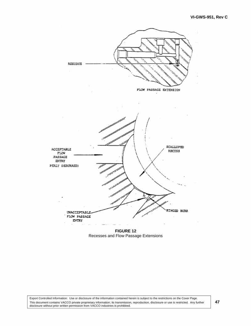
Scalloped and Counter Bore Recesses and Flow Passage Extensions ........................................... 40 10.1.4
11.0 SURFACE REFINING ....................................................................................................................... 41
11.1 Polishing ............................................................................................................................................ 41
12.0 RESPONSIBILITY ............................................................................................................................. 41
LIST OF TABLES
Table 1 Centerline Deviation ............................................................................................................................. 22
Table 2 Stock Diameter ..................................................................................................................................... 22
Table 3 Runout .................................................................................................................................................. 22
Table 4 Flatness Relationship, Waviness, Roughness ..................................................................................... 23
Table 5 Tolerance – Surface Finish Relationship ............................................................................................. 23
Table 6 Exception to Block Angular Tolerance for Chamfers ........................................................................... 24
Table 7 Burr Classifications............................................................................................................................... 24
Table 8 Standard Knurls .................................................................................................................................... 25
Table 9 Standard Internal Machine Centers ..................................................................................................... 25
Table 10 Standard External Machine Centers ................................................................................................... 26
Table 11 Standard Hollow Part Machine Centers ............................................................................................. 27
Table 12 Permissible Misalignment for Profiled Surfaces ................................................................................. 28
Table 13 Screw Thread Surface Finish ............................................................................................................. 29
Table 14 Tapped Hole Countersink Diameters ................................................................................................. 29
Table 15 Screw Thread Chamfers .................................................................................................................... 30
Table 16 Undercuts for External Threads ......................................................................................................... 31
Table 17 Undercuts for Internal Threads .......................................................................................................... 32
Table 18 Standard Undercuts ........................................................................................................................... 33

VI-GWS-951, Rev C
Export Controlled Information: Use or disclosure of the information contained herein is subject to the restrictions on the Cover Page.
This document contains VACCO private proprietary information; its transmission, reproduction, disclosure or use is restricted. Any further disclosure without prior written permission from VACCO industries is prohibited.
v
LIST OF FIGURES
Figure 1 Thread with Relief .............................................................................................................................. 16
Figure 2 Thread Through Single Wall .............................................................................................................. 16
Figure 3 Equal Spacing .................................................................................................................................... 34
Figure 4 Surface Finish .................................................................................................................................... 35
Figure 5 Lay Symbols ........................................................................................................................................ 36
Figure 6 Machined Surface Deviations ............................................................................................................. 37
Figure 7 Types of Burrs ..................................................................................................................................... 42
Figure 8 Critical Areas for Drill and Reamer Breakage ..................................................................................... 43
Figure 9 Critical Deburring Areas and Contamination Removal ....................................................................... 44
Figure 10 Passage Intersections ....................................................................................................................... 45
Figure 11 Effects of Scoring on Sealing Surfaces ........................................................................................... 46
Figure 12 Recesses and Flow Passage Extensions ......................................................................................... 47
Figure 13 Effects of Insufficient Coolant During Deep Drilling .......................................................................... 48
VI-GWS-951, Rev C
Export Controlled Information: Use or disclosure of the information contained herein is subject to the restrictions on the Cover Page.
This document contains VACCO private proprietary information; its transmission, reproduction, disclosure or use is restricted. Any further disclosure without prior written permission from VACCO industries is prohibited.
6
GENERAL WORKMANSHIP STANDARD:
MACHINED PARTS, TOLERANCES, SURFACE FINISH,
AND STANDARD CONFIGURATIONS
1.0 SCOPE
1.1 Scope
This specification covers the requirements for tolerances, surface finishes and standard
configurations for machined parts and final assemblies.
1.2 Justification
There is no government or industry specification equivalent to this specification.
2.0 APPLICABLE DOCUMENTS
2.1 Government Documents
FED-STD-H28 Screw Thread Standards for Federal Services
MIL-S-70335 MIL-S-70335
MIL-S-7742 Screw Threads, Standard, Optimum Selected Series, General Specification for
2.2 Non-Government Documents
ASME Y14.5M American National Standard Institute (ANSI) Specifications Dimensioning and Tolerancing
3.0 REQUIREMENTS
In the event of any conflict between the requirements of this specification and drawings calling
out this specification, the requirements of the drawing shall take precedence. Exceptions are as
stipulated in the Requirements section.
NOTE: All tooling used in the processes (during setup and operation), shall be checked by
the person using the tool, to ensure it is in good operating condition and free of damage
before and after its use.
3.1 In-Process Parts Protection
Machined parts shall be protected, handled, and stored in accordance with VACCO standards.

VI-GWS-951, Rev C
Export Controlled Information: Use or disclosure of the information contained herein is subject to the restrictions on the Cover Page.
This document contains VACCO private proprietary information; its transmission, reproduction, disclosure or use is restricted. Any further disclosure without prior written permission from VACCO industries is prohibited.
7
3.2 Machined Surface Finishes
The specific method used to machine a surface shall be optional. Drawing notes that specify "Lap
16" or "Grind 20" shall not restrict manufacturing to that particular process, provided the alternate
process used results in a surface roughness not greater than that specified on the drawing (see
paragraph 5.1.1 for the definition of roughness).
3.3 Surface Cleaning
Surface Cleaning of Machined Metal Parts 3.3.1
Machined parts surfaces shall be cleaned per standard commercial practices unless otherwise
specified.
3.4 Machining Fluids for Plastics
Plastics shall be machined dry (no lubricant) and be cooled with air or an air/water mist. Organic
lubricants or coolants may be used only with the approval of VACCO lndustries Engineering.
3.5 Detailed Requirements
Engineering 3.5.1
3.5.1.1 Tolerances
3.5.1.1.1 Form Tolerance
Form tolerance shall apply to all dimensions, whereas the part can be of any shape or size
providing it is within the tolerance envelope. Specific requirements, such as flatness, roundness,
parallelism and angularity, shall be indicated by the Geometric Characteristic Symbols as shown in
the applicable ASME Y14.5 standard and on the engineering drawing. See also paragraphs 5.1.4,
5.1.5, 5.1.6 and 5.1.7 for definitions of flatness, roundness, parallelism, and angularity, respectively.
3.5.1.1.2 Positional Tolerance
Positional tolerance shall apply as specified in this specification unless a closer tolerance is required
by the drawing and is so indicated by one of the Geometric Characteristic Symbols, as shown in the
applicable ASME Y14.5 standard and on the engineering drawing.

VI-GWS-951, Rev C
Export Controlled Information: Use or disclosure of the information contained herein is subject to the restrictions on the Cover Page.
This document contains VACCO private proprietary information; its transmission, reproduction, disclosure or use is restricted. Any further disclosure without prior written permission from VACCO industries is prohibited.
8
3.5.1.1.3 Block Angular Tolerance
The block angular tolerance of ±2° shall apply to all implied (non-dimensioned) angles as well as all
specified angles having no tolerance called out on the drawing (see paragraph 5.1.8 for definition of
block tolerance).
3.5.1.2 Centerline Deviation
Holes, slots, and tangs presented on the true centerline of a part, but not dimensioned, shall be
permitted to deviate from the centerline as shown in Table 1. The allowable deviation shall be a
function of the tolerance of the overall width of the part containing the feature (see paragraph 5.1.9
for definition of centerline).
3.5.1.3 Concentricity
Cylindrical surfaces having a common axis shall be concentric as specified in paragraphs 3.5.1.3.1
through 3.5.1.3.4 (see paragraph 5.1.10 for definition of concentricity).
3.5.1.3.1 Two Cylindrical Surfaces
When two cylindrical surfaces having a common axis are machined, they shall be concentric within
a total indicator reading (TIR) or 0.010 inch (see paragraphs 5.1.11 and 5.1.12 for definition for
cylindricity and TIR).
3.5.1.3.2 Three or More Cylindrical Surfaces
When more than two cylindrical surfaces having a common axis are machined, the concentricities
shall be measured using the diameter with the closest diametrical tolerance as a reference. The
requirement specified in paragraph 3.5.1.3.1 shall then be followed.
3.5.1.3.3 Stock Diameter and Machined Surfaces
When one surface is specified as "stock diameter" and one or more surfaces are machined, each
machined surface shall be concentric to the stock diameter as specified in Table 2.
3.5.1.3.4 Hole Runout
The runout of deep drilled holes (depth of drilled holes six or more times the drill diameter) shall be
within 0.030 inch TIR concentricity of the adjacent diameter on center drilled parts. The runout of
other holes shall be within the limits of Table 3 (see paragraphs 5.1.13, 5.1.13.1 and 5.1.13.2 for
definitions of runout, circular runout, and total runout).

VI-GWS-951, Rev C
Export Controlled Information: Use or disclosure of the information contained herein is subject to the restrictions on the Cover Page.
This document contains VACCO private proprietary information; its transmission, reproduction, disclosure or use is restricted. Any further disclosure without prior written permission from VACCO industries is prohibited.
9
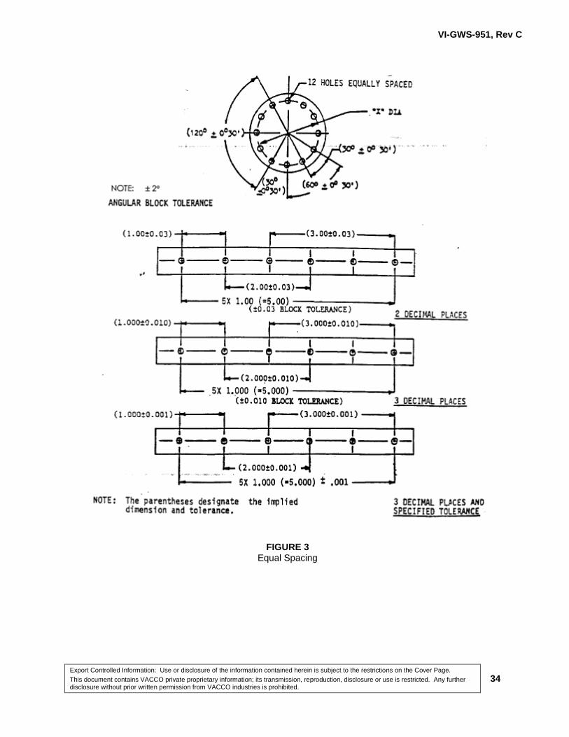
3.5.1.4 Equal Spacing
An implied dimension and tolerance shall be considered to exist between any two holes or other
features of a group governed by an applicable note or symbol for equal spacing. The tolerance on
the overall dimension shall apply to holes or individual features, adjacent as well as non-adjacent
(non-accumulative) (see Figure 3). For exceptions to the angular tolerance, see paragraph
3.5.1.1.3.
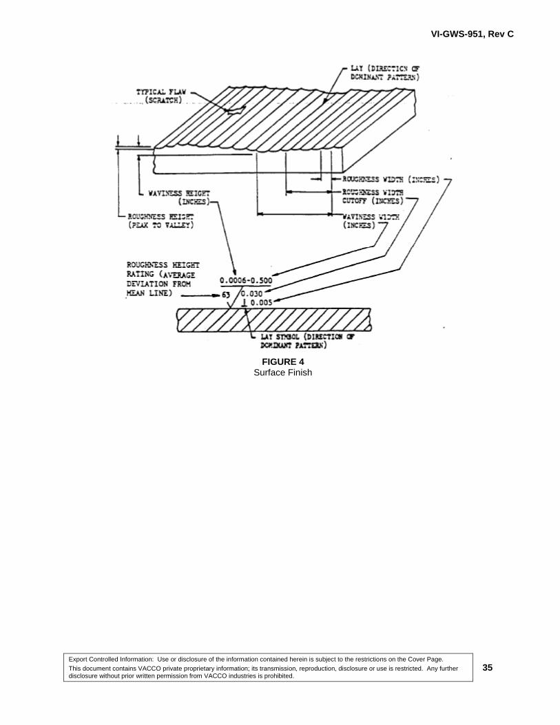
3.5.1.5 Surface Finish-Transition Areas
Surface finish in areas of transition, such as chamfers and fillets, shall conform to the roughest of
the adjacent areas unless otherwise indicated (see Figure 4). See paragraph 5.1.14 for definition of
surface.
3.5.1.6 Flatness and Straightness
3.5.1.6.1 Flatness
If the flatness is specified and surface roughness or waviness height is not specified, the values of
surface roughness and waviness height which correspond to the flatness requirement as described
in paragraph 3.5.1.13 and shown in Table 4 shall apply, subject to the limitations of 3.5.1.12.
3.5.1.6.2 Straightness
All linear features shall be straight within the total envelope tolerance, e.g., if a feature is shown to
have a ± 0.010 tolerance on size, that feature shall be straight within 0.020 inch (see paragraph
5.1.15 for definition of straightness).
3.5.1.7 Centerline of Holes or Other Features Governed by a Single Centerline
The centerline of holes or other features governed by a single centerline shall lie within the
tolerance specified for the location of the centerline of the part (see Table 1.)
3.5.1.8 In-Line Holes (Pertaining to Holes on the Same Axis)
All holes thus specified shall meet the required diametrical tolerance individually. In addition, all
holes so specified shall simultaneously accept a single cylindrical gauge of a diameter, or
diameters, equal to the minimum specified for each hole.
VI-GWS-951, Rev C
Export Controlled Information: Use or disclosure of the information contained herein is subject to the restrictions on the Cover Page.
This document contains VACCO private proprietary information; its transmission, reproduction, disclosure or use is restricted. Any further disclosure without prior written permission from VACCO industries is prohibited.
10
3.5.1.9 Perpendicularity
When a plane surface is shown perpendicular to an axis or other plane surface or surfaces, and a
tolerance is not specified on the drawing, the implied tolerance shall be the block angular tolerance
(see paragraph 3.5.1.1.3) when normality is specified in terms of TIR (see paragraph 5.1.16 for
definition of perpendicularity).
3.5.1.10 Parallelism
When parallelism is not specified, the distance be tween the entire two surfaces in question shall
be within the dimensional tolerance specified on the drawing. (Dimensions apply for the full surface
which they indicate.)
3.5.1.11 Roundness/Cylindricity
To isolate roundness as an individual function and because roundness may be confused with
cylindricity or concentricity by use of some gauging methods, roundness shall be checked at
numerous points around the diameter perpendicular to the common axis. Cylindricity shall be
checked along the entire length; however, cylindricity checks roundness, straightness end
parallelism.
3.5.1.12 Surface Finish and Tolerance
3.5.1.12.1 The surface finish of any machined surface shall be governed by the closest tolerance given for any
dimension of that surface.
3.5.1.12.2 Table 5 shall be used to determine the maximum surface roughness permitted for a specified
tolerance. See Figure 5 for lay symbols. Surfaces shall contain no discontinuities (e.g., scratches,
nicks or gouges) with a depth greater than 10 times the RHR callout expressed in millionths of an
inch, when the width is less than 40 times the RHR callout, expressed in millionths. Discontinuities
shall not exceed 1 per square inch of surface; e.g., a surface area of five square inches is allowed
to have a maximum of five discontinuities.
EXAMPLE: For a surface finish of 63 RHR,
D = 0.000063 X 10 = 0.0006 inch, and
W = 0.000063 X 40 = 0.0025 inch

VI-GWS-951, Rev C
Export Controlled Information: Use or disclosure of the information contained herein is subject to the restrictions on the Cover Page.
This document contains VACCO private proprietary information; its transmission, reproduction, disclosure or use is restricted. Any further disclosure without prior written permission from VACCO industries is prohibited.
11
3.5.1.12.3 Nicks and Dings on Body Blocks
It is not necessary to reject blank body blocks (identified as "Block-XX", where XX is any number)
for any minor nicks and dings that occur along the corners for the following reasons:
3.5.1.12.3.1 Prior to machining, the machinist breaks the corners with a file or equivalent.
3.5.1.12.3.2 Normal handling of these blocks may cause additional nicks and dings. It is not necessary to handle
these blocks in a manner that would completely eliminate the nicks and dings.
3.5.1.12.3.3 Neither VACCO nor the customer use the corners for indicating or assembly. Any nicks and dings
are cosmetic only.
3.5.1.12.3.4 Any nicks and dings which have occurred during manufacturing will be blended out during final
deburr.
3.5.1.12.4 Any gouges on the corner of the block deeper than .060 or upset metal over .030 above the surface
should be forwarded to Engineering for disposition.
3.5.1.13 Waviness Height, Cut-Off and Flatness
Machined surfaces designated as flat shall have a waviness height not greater than and a surface
finish within the limits listed in Table 4, depending upon the required flatness. Waviness height shall
not be cumulative and applies only to a one-half inch increment on any portion of a surface. The full
waviness height tolerance shall apply for the extent of any surface which is less than 0.500 inch
long. A 0.030 inch cut-off shall be used (see Figure 6).
3.5.1.14 Free State Variation
Free state variation, unless otherwise specified, shall be within an elastic range that will allow the
part to be brought within drawing tolerances by forces equivalent to those that can be exerted by
employing the expected method of assembly (see paragraph 5.1.17 for definition of free state
variation).
Operations 3.5.2
3.5.2.1 Chamfer
The tolerances specified in Table 6 shall apply to chamfer angles (see paragraph 5.1.18 for
definition of chamfer).

VI-GWS-951, Rev C
Export Controlled Information: Use or disclosure of the information contained herein is subject to the restrictions on the Cover Page.
This document contains VACCO private proprietary information; its transmission, reproduction, disclosure or use is restricted. Any further disclosure without prior written permission from VACCO industries is prohibited.
12
3.5.2.2 Counterbore and Spot face
For counter boring and spot facing operation the block angular tolerance (paragraph 3.5.1.1.3) shall
apply and the surface roughness shall be 125 maximum.
3.5.2.3 Countersink
For countersinking operation the surface roughness shall be 125 maximum. Pilot drilled holes may
be oversized if the material thickness is less than the full contour of the countersink.
3.5.2.4 Deburring
All parts shall be deburred (see paragraph 5.1.19 for definition of burr and 5.1.19.1, 5.1.19.2 and
5.1.19.3 for type of burrs). Appendix A contains more explanation on the removal of burrs.
3.5.2.4.1 Breaking of Edges
The size of a break resulting from deburring an edge shall be determined from the surface finish
specified for the two adjacent surfaces. The coarser of these two surfaces shall determine the size
of the break. A broken edge shall signify that either a radius or a chamfer is acceptable as the
result of the deburring process. All edges shall be broken as follows.
a) For edges specified as sharp, the edges shall be broken 0.000 to 0.005 inch.
b) For finishes 32 or finer, break edge 0.003 to 0.010 inch.
c) For finishes 33 or coarser, break edge 0.005 to 0.015 inch.
3.5.2.4.2 Burrs
Acceptance of burrs shall depend upon the surface finish required for the surfaces, the type, size
(protrusion) and position. The size of the burr shall be determined by visual inspection and
magnification level per Table 7 and paragraph 4.3.2. All levels of inspection shall be conducted
using an illumination level of 100 ± 10 foot candles and 20/20 to 20/30 vision. The maximum
acceptable protrusion shall be that size of burr which does not protrude discernibly above a surface
under the conditions specified in Table 7.
Drilling 3.5.3
The specified hole shall be made by any process that maintains the block tolerance and provides a
surface roughness of 125 maximum. The diametrical tolerance of holes of greater than four but less
than 10 drill diameters deep shall be within twice the normal tolerance for that diameter.
VI-GWS-951, Rev C
Export Controlled Information: Use or disclosure of the information contained herein is subject to the restrictions on the Cover Page.
This document contains VACCO private proprietary information; its transmission, reproduction, disclosure or use is restricted. Any further disclosure without prior written permission from VACCO industries is prohibited.
13
3.5.3.1 Drill Breakthrough
A part shall be acceptable if drilling causes a protuberance or breakthrough providing all features,
i.e., size depth, drill point angle, and related dimensions, are within specified tolerances.
Knurling 3.5.4
The circular pitch of the knurl for use with the corresponding diameters shall be as shown in Table
8. The tooth angle of the knurl of hard materials shall be 60 ± 5 degrees and for soft materials (150
BHN or less) it shall be 90 ± 5 degrees.
Machined Surface Deviations 3.5.5
3.5.5.1 Single Flat or Curved Surfaces
Where two or more machined cuts (Figure 6a) are required to produce a single surface, the
maximum misalignment of adjacent cuts shall not exceed 0.003 inch on parts less than 12 X 12
inches (144 square inches) in area and 0.006 inch on parts greater than 12 X 12 inches in area,
unless otherwise specified. The minimum cutter radius shall be 0.063 inch.
3.5.5.2 Intersecting Surfaces (One Surface Not Machined)
When two or more surfaces intersect and one of the surfaces is not machined (Figure 6b), or where
an unmachined and a machined surface are in the same plane (Figure 6c), the misalignment of the
surfaces shall not exceed 0.030 inch with a 0.063 inch minimum fillet radius produced by the cutter.
3.5.5.3 Intersecting Surfaces (Both Surfaces Machined)
Where two or more machined surfaces intersect, the misalignment between any of the surfaces
shall not exceed 0.010 inch and the fillet radius produced by the cutter shall be 0.010 ± 0.005 inch
(Figure 6d).
3.5.5.4 Intersecting Surfaces (After Plating)
When two intersecting plated surfaces are machine finished after plating, the plating shall not be
removed from the undercut.
Machining Centers 3.5.6
When the drawing allows a machining center, but does not specify or control its dimensions, the
following requirements shall apply:

VI-GWS-951, Rev C
Export Controlled Information: Use or disclosure of the information contained herein is subject to the restrictions on the Cover Page.
This document contains VACCO private proprietary information; its transmission, reproduction, disclosure or use is restricted. Any further disclosure without prior written permission from VACCO industries is prohibited.
14
3.5.6.1 Internal Machining Centers
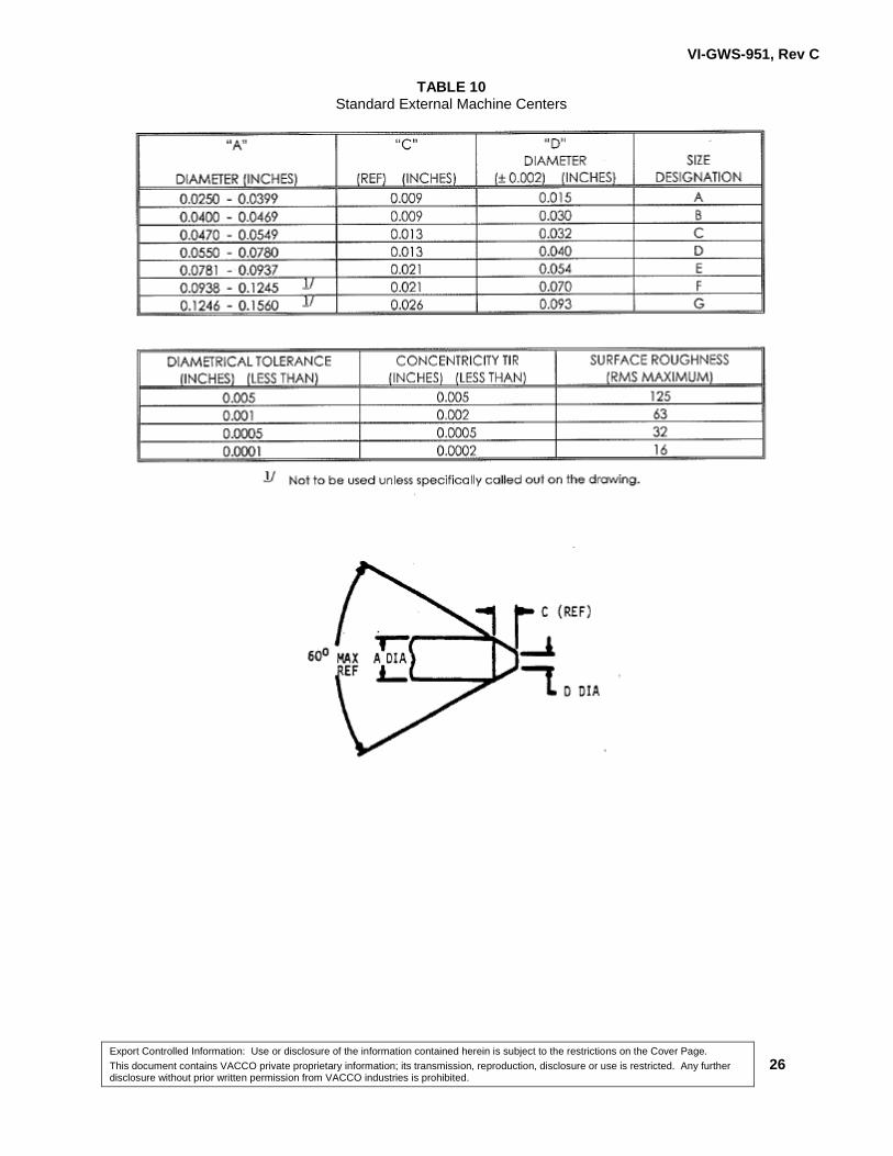
Internal machining centers shall be as shown in Table 9.
3.5.6.2 External Machining Centers
External machining centers shall be as shown in Table 10.
3.5.6.3 Hollow Part Machining Centers
Hollow part machining centers shall be as shown in Table 11.
Plating 3.5.7
All dimensions and tolerances for plated or anodized parts shall apply after processing has been
completed.
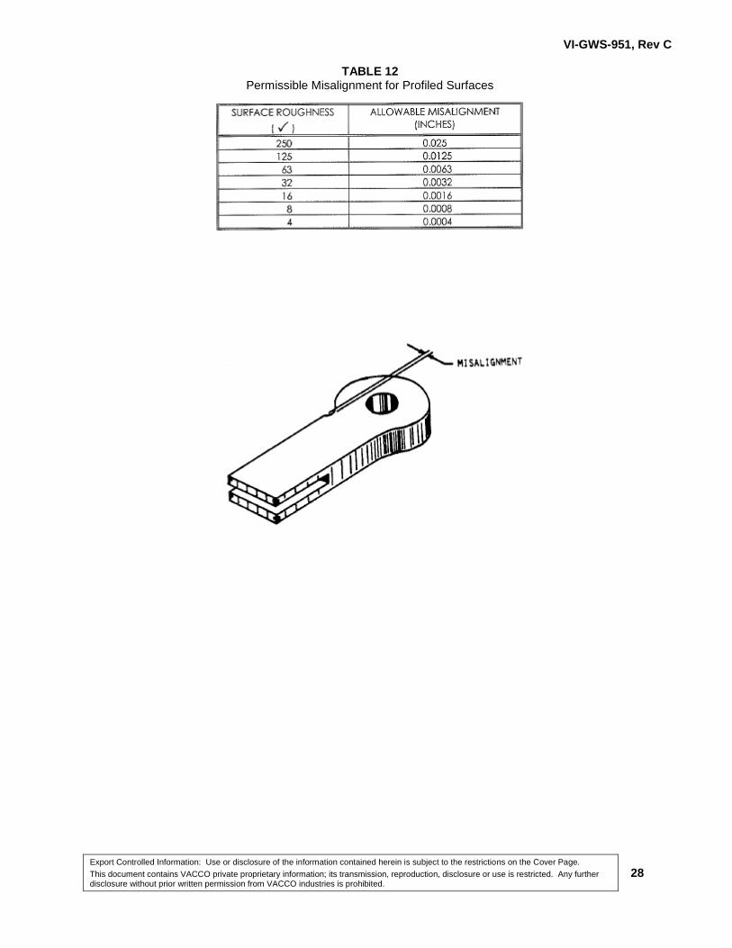
Profiled Surfaces 3.5.8
Where parts are contour-machined by milling, sawing, hand finishing or flame cutting, the
misalignment of intersecting adjacent surfaces shall not exceed the values listed in Table 12 for the
specified surfaces. The maximum misalignment shall be governed by the rougher of the two
adjacent surfaces.
Radii (Fillet) 3.5.9
Unless otherwise specified on the engineering drawing, the machined fillet radii produced by the
cutter shall be 0.010 ± 0.005 inch.
Threads 3.5.10
3.5.10.1 Standard Cut Threads
Standard cut threads shall be in accordance with MIL-S-7742 or Handbook H-28, as applicable.
Their maximum surface roughness shall be as specified in Table 13. The coarser Finish 125
specified in Table 13 for die and tap threads shall apply. When a thread rolling process is used, the
drill size shall be as recommended by the manufacturer.
3.5.10.2 Cold Rolled Threads
Internal cold rolled threads shall be in accordance with MIL-S-70335. The material shall meet the
ductility properties required for thread rolling. The cold rolled thread surface finish shall be as
specified in Table 13.
VI-GWS-951, Rev C
Export Controlled Information: Use or disclosure of the information contained herein is subject to the restrictions on the Cover Page.
This document contains VACCO private proprietary information; its transmission, reproduction, disclosure or use is restricted. Any further disclosure without prior written permission from VACCO industries is prohibited.
15
3.5.10.3 Tapped Hole Countersink Diameters
Tapped hole countersink diameters shall be as shown in Table 14.
3.5.10.4 Screw Thread Chamfers
Screw thread chamfers shall be as shown in Table 15.
Undercuts 3.5.11
When the engineering drawing calls out for thread undercuts, but does not specify or control its
dimensions, the following requirements shall apply:
3.5.11.1 Undercuts for External Threads
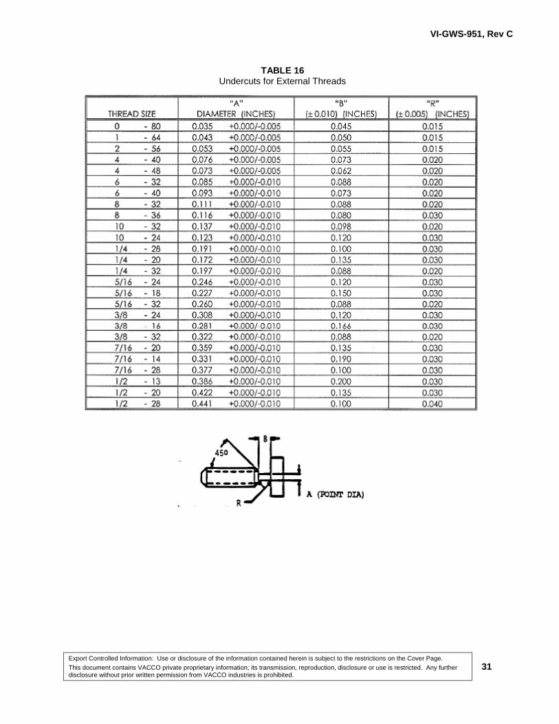
Undercuts for external threads shall be as specified in Table 16.
3.5.11.2 Undercuts for Internal Threads
Undercuts for internal threads shall be as shown in Table 17. Table 17 shall apply only to diameters
greater than 0.375 inch.
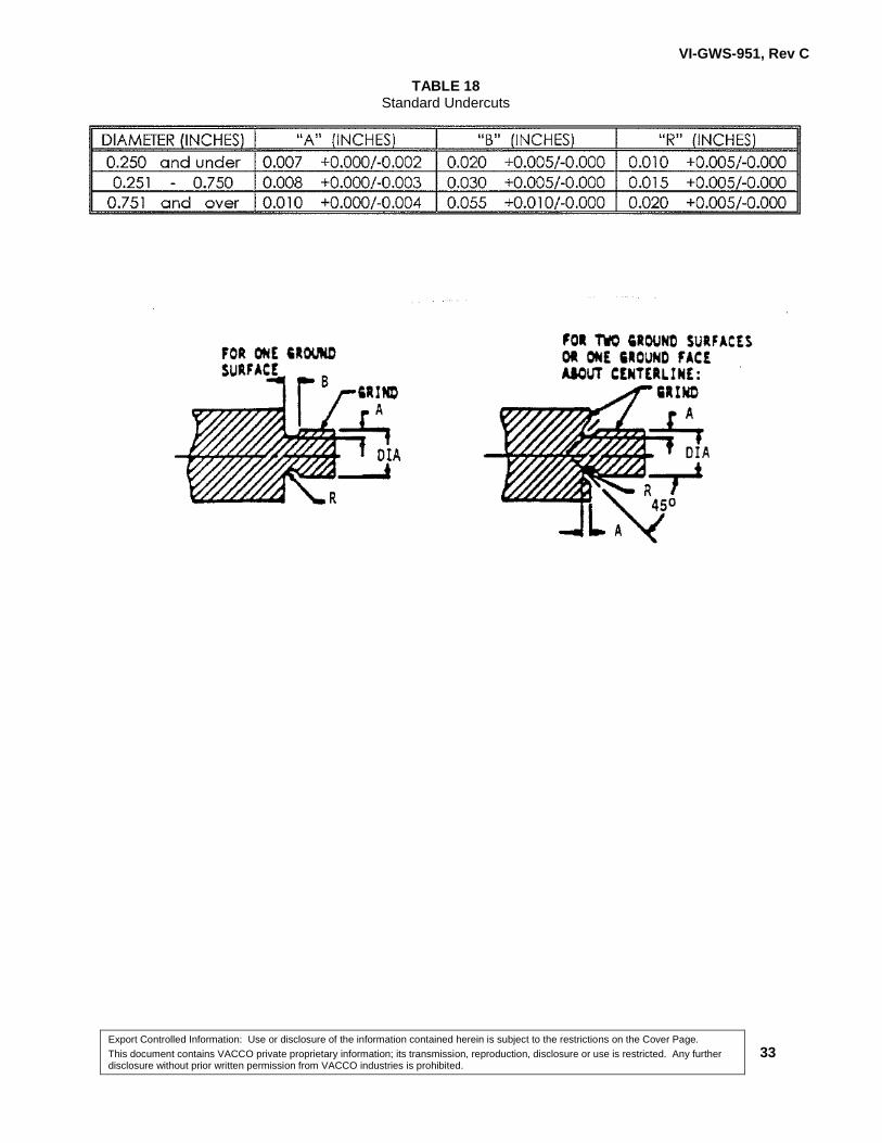
3.5.11.3 Standard Undercuts
Standard undercuts shall be used only in designated locations and as specified in Table 18.
Thread Depth General Practice 3.5.12
The usual method for fabricating an internal thread is to drill a pilot hole, and then cut threads into it
with a tap. On VACCO drawings, the pilot hole and the threads both have depth dimensions,
subject to the applied tolerance or the general tolerance block.
For blind, tapped internal threads, the pilot hole depth shall be drilled to print. It is acceptable for
the depth of the threads to be considered a minimum. As long as the minimum thread depth
specified on the drawing is achieved, it is acceptable for the threads to go as deep into the tapped
hole as practicable.
The diameter of the pilot hole beyond the threads is considered to be for reference only, and will not
to be subject to measurement. An exception is that obvious damage to this area due to tool
breakage or other anomaly will be subject to Engineering disposition.
3.5.12.1 Unless otherwise specified on the drawing, this general practice is not applicable to the following
conditions:

VI-GWS-951, Rev C
Export Controlled Information: Use or disclosure of the information contained herein is subject to the restrictions on the Cover Page.
This document contains VACCO private proprietary information; its transmission, reproduction, disclosure or use is restricted. Any further disclosure without prior written permission from VACCO industries is prohibited.
16
3.5.12.1.1 If the threads are cut into a pilot hole that steps down into a smaller hole, the threads shall only go
as deep as the pilot hole. See Figure 1
FIGURE 1 Thread with Relief
3.5.12.1.2 If a thread relief is described, the threads shall not extend beyond the thread relief. See Figure 1
3.5.12.1.3 If the pilot hole crosses through another hole, the thread shall only go through one wall. See
Figure 2.
FIGURE 2 Thread Through Single Wall

VI-GWS-951, Rev C
Export Controlled Information: Use or disclosure of the information contained herein is subject to the restrictions on the Cover Page.
This document contains VACCO private proprietary information; its transmission, reproduction, disclosure or use is restricted. Any further disclosure without prior written permission from VACCO industries is prohibited.
17
3.5.12.1.4 If the pilot hole has a specific surface finish beyond the threads, then the thread depth with the
proper tolerance shall be to print. The diameter of the pilot hole beyond the threads is subject to the
applied diameter, tolerance, and surface finish, and it shall be inspected. See Figure 1.
4.0 QUALITY ASSURANCE PROVISIONS
4.1 Responsibility for Inspection
Unless otherwise specified in the contract or order, the Quality Assurance or Inspection organization
of the agency, supplier, or facility performing the process shall be responsible for assuring the
performance of all inspection specified herein. For purchased parts or services, except as otherwise
specified, the supplier may utilize his own facilities or any commercial laboratory acceptable to the
buyer.
4.2 Inspection
Inspection to determine compliance with the applicable drawing and/or Section 3 requirements shall
be performed in accordance with the corresponding verification paragraphs of 4.3.1 and 4.3.2.
4.3 Inspection Methods
Dimensions 4.3.1
All machined parts shall be examined to verify compliance with paragraph 3.5 and drawing
requirements. Standard gauges and measurement methods shall be used for this inspection.
Visual Examination 4.3.2
All machined parts shall be visually examined to verify compliance with paragraph 3.5 and the
drawing. Visual examination shall be performed without magnification except when inspecting for
burrs, which shall be inspected using the level of magnification required by Table 7, or when
inspecting small parts which cannot be effectively inspected without the use of magnification. If an
anomaly is observed during visual inspection magnification shall be used to classify the defect and
to determine the acceptability of the product. Magnification shall be illuminated by a light source
sufficient to perform the inspection.
VI-GWS-951, Rev C
Export Controlled Information: Use or disclosure of the information contained herein is subject to the restrictions on the Cover Page.
This document contains VACCO private proprietary information; its transmission, reproduction, disclosure or use is restricted. Any further disclosure without prior written permission from VACCO industries is prohibited.
18
5.0 NOTES
5.1 Definitions
Roughness 5.1.1
Roughness consists of the finer irregularities in the surface texture, including those irregularities
which result from the inherent action of the production process. These are considered to include
traverse feed marks and other irregularities within the limits of the roughness-width cut off (Figure
4).
Precision Machining 5.1.2
Precision machining, as used in this specification, includes all dimensions with a total tolerance of
0.0001 to 0.0005 inch and Ultra Precision Machining (UPM) tolerances which are less than 0.0001
inch total tolerance.
Dimensional Tolerance 5.1.3
Dimensional tolerance is defined by the difference between two limiting sizes as a means of
specifying the degree of accuracy; e.g., for 2.500 ± 0.01 0, the tolerance is 0.020 inch.
Flatness 5.1.4
Flatness is the condition of a surface having all elements in one plane. A flatness tolerance
specifies a tolerance zone confined by two parallel planes within which the surface must lie.
Roundness 5.1.5
Roundness is a condition of a surface of revolution such as a cylinder, cone, or sphere, where all
points of the surface intersected by any plane are equidistant from the axis.
Parallelism 5.1.6
Parallelism is a condition of a surface or line which is equidistant at all points from a datum plane or
axis. A parallel tolerance specifies a zone confined by two planes parallel to a datum feature (axis,
surface or cylinder).
Angularity 5.1.7
Angularity is the condition of a surface, axis or center plane which is at a specified angle (other than
90 degrees, which would be perpendicularity) from a plane or axis.

VI-GWS-951, Rev C
Export Controlled Information: Use or disclosure of the information contained herein is subject to the restrictions on the Cover Page.
This document contains VACCO private proprietary information; its transmission, reproduction, disclosure or use is restricted. Any further disclosure without prior written permission from VACCO industries is prohibited.
19
Block Tolerance 5.1.8
Block tolerance is a tolerance given in the title block of the drawing which defines a tolerance that is
not specified on the body of the drawing.
Centerline 5.1.9
A centerline shown in the center of a part and not dimensioned in reference to any surface shall be
defined as being the true center of that part. An example would be the following: a hole or feature
lies on a centerline which is shown directly in the center of a part. The width of a part is
dimensioned 0.75 ± 0.03 inch. This means that the width of the part may vary from 0.72 to 0.78
inch, but the centerline in either case must be equidistant from the two edges of the part, within the
tolerances specified in Table 1.
Concentricity 5.1.10
Concentricity is a condition in which two or more regular features (such as cylinders, cones,
spheres, etc.), in any combination, have a common axis (or centerline). The deviation from
concentricity is eccentricity. The eccentricity may be measured between any two surfaces. In the
case of multiple surfaces, the eccentricity of each surface must be measured in respect to a
designated reference surface. In machining practice, concentricity (eccentricity) is normally called
out and measured as Total Indicator Reading (TIR). The actual eccentricity (centerline
displacement between two surfaces) is one-half of the TIR value.
Cylindricity 5.1.11
Cylindricity is a condition of a surface of revolution in which all elements form a cylinder. A
cylindricity tolerance specifies a tolerance zone confined to the annular space between two
concentric cylinders within which the surface must lie.
Total Indicator Reading (TIR) 5.1.12
The range of variation from a true surface (highest to lowest points) on the entire surface including
roughness and waviness which can be used to define the surface of a plane, cylinder, cone, sphere
or other geometrical shape.
Runout 5.1.13
A runout tolerance establishes a means of controlling the functional relationship of two or more
features of a part within the allowable errors of concentricity, perpendicularity and alignment of the
features. It also takes into account variations in round ness, straightness, flatness, and parallelism
VI-GWS-951, Rev C
Export Controlled Information: Use or disclosure of the information contained herein is subject to the restrictions on the Cover Page.
This document contains VACCO private proprietary information; its transmission, reproduction, disclosure or use is restricted. Any further disclosure without prior written permission from VACCO industries is prohibited.
20
of individual surfaces. There are two types of runout control, circular runout and total runout, as
follows.
5.1.13.1 Circular Runout
A circular runout provides control of circular elements of a surface. The tolerance is applied
independently at any circular measuring position as the part is rotated 360°. Where applied to
surfaces constructed around a datum axis, circular runout may be used to control the cumulative
variations of circularity and coaxiality. Where applied to surfaces constructed at right angles to the
datum axis, circular runout controls circular elements of a plane surface (see ASME Y14.5 for
illustrations).
5.1.13.2 Total Runout
A total runout provides composite control of all surface elements. The tolerance is applied
simultaneously to all circular and profile measuring positions as the part rotates 360°. Where
applied to surfaces constructed around a datum axis, total runout is used to control cumulative
variations of circularity, straightness, coaxiality, angularity, taper and profile of a surface. Where
applied to surfaces constructed at right angles to a datum axis, total runout controls cumulative
variations of perpendicularity (to detect wobble) and flatness (to detect concavity or convexity) (see
ASME Y 14.5 for illustrations).
Surface 5.1.14
A surface is considered to extend to the point where it intersects another surface or becomes
tangent to an area of transition. The control exercised by the individual symbol ends at this point.
Straightness 5.1.15
Straightness is a condition where an element of a surface is a straight line. A straightness tolerance
specifies a tolerance zone uniform width along a straight line within which all points of the
considered line must lie.
Perpendicularity 5.1.16
Perpendicularity is the condition of surfaces, axes or lines which are at right angles to each other. A
perpendicularity tolerance specifies a zone confined by two parallel planes perpendicular to a datum
plane within which the surface of a feature must lie.

VI-GWS-951, Rev C
Export Controlled Information: Use or disclosure of the information contained herein is subject to the restrictions on the Cover Page.
This document contains VACCO private proprietary information; its transmission, reproduction, disclosure or use is restricted. Any further disclosure without prior written permission from VACCO industries is prohibited.
21
Free State Variation 5.1.17
Free state variation is defined by distortion of a part within an elastic range after removal of forces
applied during manufacturing. This distortion is principally due to weight and flexibility of the part
and the release of internal stresses resulting from fabrication.
Chamfer 5.1.18
A chamfer is defined by an angle and a linear dimension, or by two linear dimensions (see ASME
Y14.5 for illustrations).
Burr 5.1.19
A burr is a rough piece or protrusion extending above the surface of a machined part. It is generally
located at, or adjacent to, the intersection of two surfaces. This protrusion may or may not be solidly
attached to the part. See Appendix A for more explanation.
5.1.19.1 Type 1 - Sharp Protruding Burr
This burr protrudes above the surface, is firmly attached to the part, and presents a sharp cutting
edge. It is normally found at an edge and can be the result of machining forcing a lip or edge into an
existing surface, or handling damage (see Table 7). See Appendix A for more explanation.
5.1.19.2 Type 2 - Loose or Weakly Attached Burr
This burr protrudes above the surface and is weakly attached to the part. It may be in any position,
including flattened against the surface or standing. The flattened or feather edged burr can result
from a tumble deburring operation that does not remove the burr from the part. The standing burr of
this type indicates lack of deburring, for this burr is usually removed with ease (see Table 7).
5.1.19.3 Type 3 - Protuberance
This burr protrudes above the surface, is firmly attached to the part, and is not sharp. This type is
usually the result of incomplete burr removal (see Table 7).

VI-GWS-951, Rev C
Export Controlled Information: Use or disclosure of the information contained herein is subject to the restrictions on the Cover Page.
This document contains VACCO private proprietary information; its transmission, reproduction, disclosure or use is restricted. Any further disclosure without prior written permission from VACCO industries is prohibited.
22
TABLE 1 Centerline Deviation
TABLE 2 Stock Diameter
TABLE 3 Runout

VI-GWS-951, Rev C
Export Controlled Information: Use or disclosure of the information contained herein is subject to the restrictions on the Cover Page.
This document contains VACCO private proprietary information; its transmission, reproduction, disclosure or use is restricted. Any further disclosure without prior written permission from VACCO industries is prohibited.
23
TABLE 4 Flatness Relationship, Waviness, Roughness
TABLE 5 Tolerance – Surface Finish Relationship

VI-GWS-951, Rev C
Export Controlled Information: Use or disclosure of the information contained herein is subject to the restrictions on the Cover Page.
This document contains VACCO private proprietary information; its transmission, reproduction, disclosure or use is restricted. Any further disclosure without prior written permission from VACCO industries is prohibited.
24
TABLE 6 Exception to Block Angular Tolerance for Chamfers
TABLE 7 Burr Classifications

VI-GWS-951, Rev C
Export Controlled Information: Use or disclosure of the information contained herein is subject to the restrictions on the Cover Page.
This document contains VACCO private proprietary information; its transmission, reproduction, disclosure or use is restricted. Any further disclosure without prior written permission from VACCO industries is prohibited.
25
TABLE 8 Standard Knurls
TABLE 9 Standard Internal Machine Centers
VI-GWS-951, Rev C
Export Controlled Information: Use or disclosure of the information contained herein is subject to the restrictions on the Cover Page.
This document contains VACCO private proprietary information; its transmission, reproduction, disclosure or use is restricted. Any further disclosure without prior written permission from VACCO industries is prohibited.
26
TABLE 10 Standard External Machine Centers

VI-GWS-951, Rev C
Export Controlled Information: Use or disclosure of the information contained herein is subject to the restrictions on the Cover Page.
This document contains VACCO private proprietary information; its transmission, reproduction, disclosure or use is restricted. Any further disclosure without prior written permission from VACCO industries is prohibited.
27
TABLE 11 Standard Hollow Part Machine Centers
VI-GWS-951, Rev C
Export Controlled Information: Use or disclosure of the information contained herein is subject to the restrictions on the Cover Page.
This document contains VACCO private proprietary information; its transmission, reproduction, disclosure or use is restricted. Any further disclosure without prior written permission from VACCO industries is prohibited.
28
TABLE 12 Permissible Misalignment for Profiled Surfaces

VI-GWS-951, Rev C
Export Controlled Information: Use or disclosure of the information contained herein is subject to the restrictions on the Cover Page.
This document contains VACCO private proprietary information; its transmission, reproduction, disclosure or use is restricted. Any further disclosure without prior written permission from VACCO industries is prohibited.
29
TABLE 13 Screw Thread Surface Finish
TABLE 14 Tapped Hole Countersink Diameters

VI-GWS-951, Rev C
Export Controlled Information: Use or disclosure of the information contained herein is subject to the restrictions on the Cover Page.
This document contains VACCO private proprietary information; its transmission, reproduction, disclosure or use is restricted. Any further disclosure without prior written permission from VACCO industries is prohibited.
30
TABLE 15 Screw Thread Chamfers
VI-GWS-951, Rev C
Export Controlled Information: Use or disclosure of the information contained herein is subject to the restrictions on the Cover Page.
This document contains VACCO private proprietary information; its transmission, reproduction, disclosure or use is restricted. Any further disclosure without prior written permission from VACCO industries is prohibited.
31
TABLE 16 Undercuts for External Threads

VI-GWS-951, Rev C
Export Controlled Information: Use or disclosure of the information contained herein is subject to the restrictions on the Cover Page.
This document contains VACCO private proprietary information; its transmission, reproduction, disclosure or use is restricted. Any further disclosure without prior written permission from VACCO industries is prohibited.
32
TABLE 17 Undercuts for Internal Threads
VI-GWS-951, Rev C
Export Controlled Information: Use or disclosure of the information contained herein is subject to the restrictions on the Cover Page.
This document contains VACCO private proprietary information; its transmission, reproduction, disclosure or use is restricted. Any further disclosure without prior written permission from VACCO industries is prohibited.
33
TABLE 18 Standard Undercuts
VI-GWS-951, Rev C
Export Controlled Information: Use or disclosure of the information contained herein is subject to the restrictions on the Cover Page.
This document contains VACCO private proprietary information; its transmission, reproduction, disclosure or use is restricted. Any further disclosure without prior written permission from VACCO industries is prohibited.
34
FIGURE 3 Equal Spacing
VI-GWS-951, Rev C
Export Controlled Information: Use or disclosure of the information contained herein is subject to the restrictions on the Cover Page.
This document contains VACCO private proprietary information; its transmission, reproduction, disclosure or use is restricted. Any further disclosure without prior written permission from VACCO industries is prohibited.
35
FIGURE 4 Surface Finish

VI-GWS-951, Rev C
Export Controlled Information: Use or disclosure of the information contained herein is subject to the restrictions on the Cover Page.
This document contains VACCO private proprietary information; its transmission, reproduction, disclosure or use is restricted. Any further disclosure without prior written permission from VACCO industries is prohibited.
36
FIGURE 5 Lay Symbols

VI-GWS-951, Rev C
Export Controlled Information: Use or disclosure of the information contained herein is subject to the restrictions on the Cover Page.
This document contains VACCO private proprietary information; its transmission, reproduction, disclosure or use is restricted. Any further disclosure without prior written permission from VACCO industries is prohibited.
37
FIGURE 6 Machined Surface Deviations

VI-GWS-951, Rev C
Export Controlled Information: Use or disclosure of the information contained herein is subject to the restrictions on the Cover Page.
This document contains VACCO private proprietary information; its transmission, reproduction, disclosure or use is restricted. Any further disclosure without prior written permission from VACCO industries is prohibited.
38
6.0 DEBURRING AND SURFACE REFINING
This section describes the deburring and surface refining standards that must be attained in order to
ensure proper performance of valves and filter, manifolds, and like equipment manufactured by
VACCO Industries.
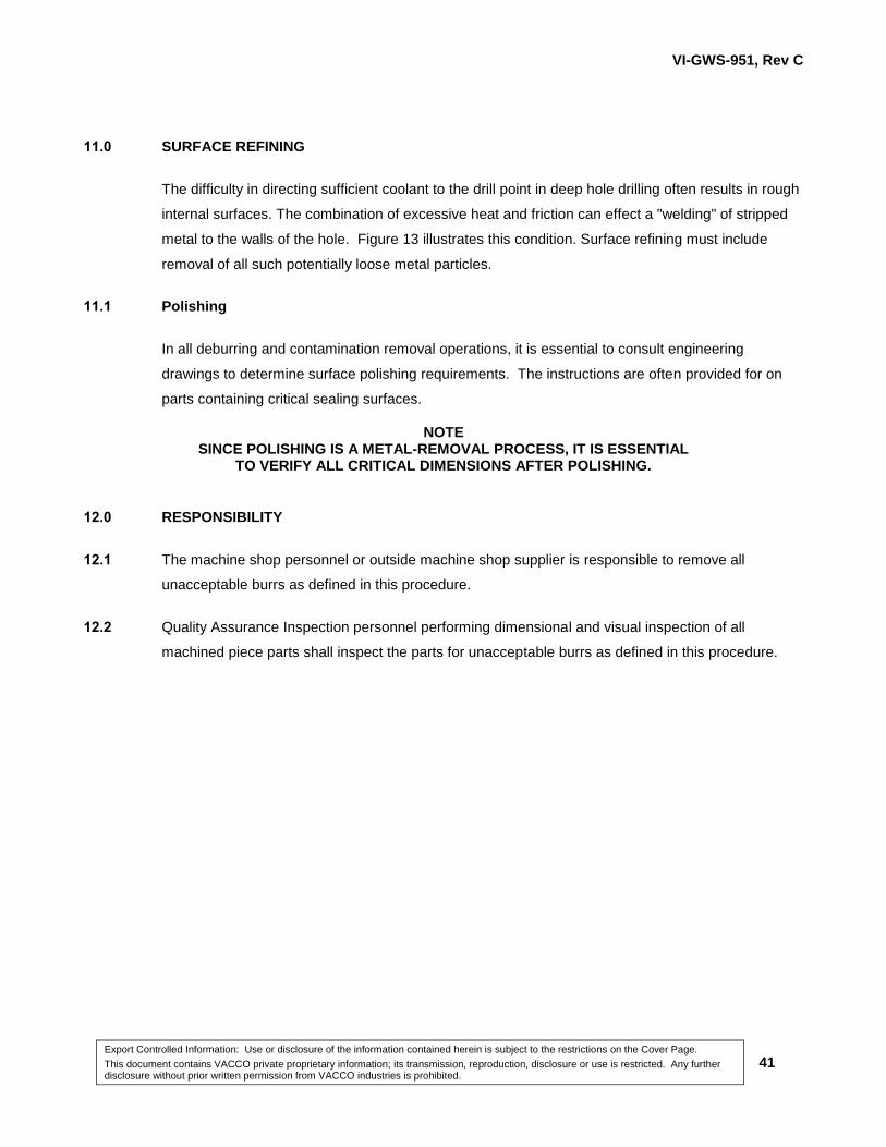
7.0 BURR ANALYSIS
7.1 A burr is an imperfection in a machined or fabricated component caused by the machining process.
The following types of burrs (illustrated in Figure 7) are often encountered.
Rolled 7.1.1
A rolled edge is acceptable unless it has altered the dimensions of the flow passage, or prevents the
smooth entry of mating part.
Crowned 7.1.2
A crowned burr is unacceptable.
Hinged 7.1.3
A hinged burr is unacceptable.
Extruded 7.1.4
Extruded material is acceptable unless it has altered the dimensions of the flow passage.
Doughnut 7.1.5
A doughnut burr is unacceptable.
Loose/Sliver 7.1.6
A loose/sliver burr is unacceptable.
Feathered 7.1.7
Feathered burrs usually occur where two unlike surfaces meet. They are acceptable in some cases
but not others, and acceptance will be established by Quality Control inspection personnel.

VI-GWS-951, Rev C
Export Controlled Information: Use or disclosure of the information contained herein is subject to the restrictions on the Cover Page.
This document contains VACCO private proprietary information; its transmission, reproduction, disclosure or use is restricted. Any further disclosure without prior written permission from VACCO industries is prohibited.
39
Rough/Broken 7.1.8
A rough/broken burr is unacceptable.
8.0 DEBURRING HAZARDS
The deburring process itself often introduces contamination in the form of dislodged fragments,
edges, or shavings from the tools being used. Nylon wool, abrasive paper, and rubber-impregnated
materials are especially susceptible to shredding and should not be used in blind or deep drilled holes
or other areas where this secondary contamination might not be easily detected or removed. In all
cases, deburring tools should be inspected frequently to ensure that they are in good condition and
not depositing residue in the flow passages or scratching critical surfaces. Figure 8 illustrates typical
areas where heavy burrs place considerable stress on drills and reamers.
9.0 CRITICAL AREAS FOR DEBURRING AND CONTAMINATION REMOVAL
9.1 Close-Toleranced Parts
Because close tolerances usually indicate close-fitting or sliding parts, even minute burrs and
contaminants must be removed.
9.2 Elbow-Type Flow Passages
Deburring and contamination removal in elbow-type flow passages is of vital concern because they
may be located downstream of the inlet filter. Therefore, any contamination that remains in these
passages has direct access to a critical area.
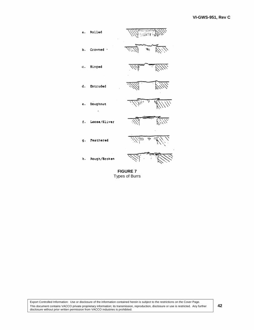
9.3 Flow Passage Intersections Near Chamfers
Before deburring or contamination removal at intersections near O-ring chamfers, an inspection of
drilled passage location must be performed. If the passage intersects with the chamfer such that the
overlap exceeds 1/4 of the chamfer width, the condition is unacceptable because the O-ring may be
clipped during installation. The resulting O-ring particles will be forced into the nozzle passage which
may cause system failure. Figure 10 illustrates both an acceptable and unacceptable drilled pas
sage chamfer intersections. Following inspection of passage location, thorough deburring and
contamination removal must be performed.

VI-GWS-951, Rev C
Export Controlled Information: Use or disclosure of the information contained herein is subject to the restrictions on the Cover Page.
This document contains VACCO private proprietary information; its transmission, reproduction, disclosure or use is restricted. Any further disclosure without prior written permission from VACCO industries is prohibited.
40
10.0 DEBURRING OF INTERCONNECTING PASSAGES
Interconnecting passages are routed through manifold blocks in various configurations, ranging from
simple 90° turns to compound angles that branch off in several directions. Because of this often
complex network of passages, there are a number of areas where proper deburring is difficult, yet
essential. The following subparagraphs, plus Figure 10 and Figure 12 highlight the required
standards.
Continuity Inspection 10.1.1
The continuity of the interconnecting passages must be verified before deburring and contamination
removal. This involves making sure that passages intersect correctly to ensure proper flow of fluid
through the system. Figure 10 shows examples of acceptable and unacceptable passage
intersections. Those units that fail to meet the illustrated standards shall be rejected.
Multi-Interconnecting Passages 10.1.2
Multi-interconnecting passages often present a problem after deburring because dislodged material
can be accidentally pushed ahead and deposited into a hidden recess or ports. This is especially
possible in sealed passages (see Paragraph 5.1.3) where routine flushing techniques may not be
effective.
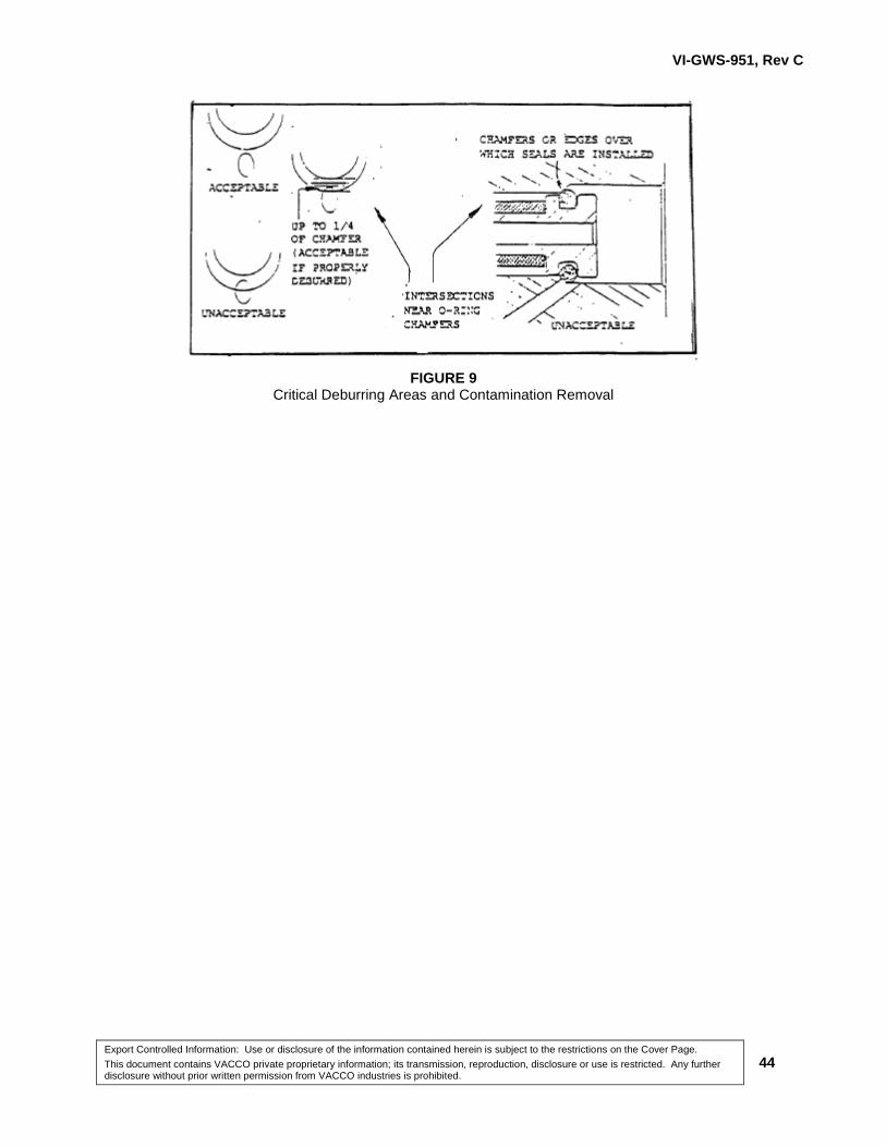
Sealing Surfaces 10.1.3
A sealing surface is an area covered by an O-ring or seal that can be severely damaged by even a
slight scratch caused by improper use of tools. They are typically called out on the drawing and
usually require a surface finish better than 16 rms. This condition is critical when the scratch extends
completely across the sealing surface (See Figure 11) because a "canal" under the O-ring seal will be
formed allowing fluid to leak past the seal. Also, if the scratch is deep enough, it can become a
reservoir for tiny particles that have been dislodged through deburring elsewhere in the unit.
Scalloped and Counter Bore Recesses and Flow Passage Extensions 10.1.4
These areas present a challenge in deburring and contamination removal because the problem area
is often hidden from view. The machining process often leaves extruded or rolled burrs at the point
where flow passages enter bores. Also, shavings may be deposited in flow passage extensions.
Careful study of the engineering drawings and plastic models will reveal the locations of these
potentially troublesome recesses and extensions (See Figure 12).
VI-GWS-951, Rev C
Export Controlled Information: Use or disclosure of the information contained herein is subject to the restrictions on the Cover Page.
This document contains VACCO private proprietary information; its transmission, reproduction, disclosure or use is restricted. Any further disclosure without prior written permission from VACCO industries is prohibited.
41
11.0 SURFACE REFINING
The difficulty in directing sufficient coolant to the drill point in deep hole drilling often results in rough
internal surfaces. The combination of excessive heat and friction can effect a "welding" of stripped
metal to the walls of the hole. Figure 13 illustrates this condition. Surface refining must include
removal of all such potentially loose metal particles.
11.1 Polishing
In all deburring and contamination removal operations, it is essential to consult engineering
drawings to determine surface polishing requirements. The instructions are often provided for on
parts containing critical sealing surfaces.
NOTE SINCE POLISHING IS A METAL-REMOVAL PROCESS, IT IS ESSENTIAL
TO VERIFY ALL CRITICAL DIMENSIONS AFTER POLISHING.
12.0 RESPONSIBILITY
12.1 The machine shop personnel or outside machine shop supplier is responsible to remove all
unacceptable burrs as defined in this procedure.
12.2 Quality Assurance Inspection personnel performing dimensional and visual inspection of all
machined piece parts shall inspect the parts for unacceptable burrs as defined in this procedure.
VI-GWS-951, Rev C
Export Controlled Information: Use or disclosure of the information contained herein is subject to the restrictions on the Cover Page.
This document contains VACCO private proprietary information; its transmission, reproduction, disclosure or use is restricted. Any further disclosure without prior written permission from VACCO industries is prohibited.
42
FIGURE 7 Types of Burrs

VI-GWS-951, Rev C
Export Controlled Information: Use or disclosure of the information contained herein is subject to the restrictions on the Cover Page.
This document contains VACCO private proprietary information; its transmission, reproduction, disclosure or use is restricted. Any further disclosure without prior written permission from VACCO industries is prohibited.
43
FIGURE 8 Critical Areas for Drill and Reamer Breakage
VI-GWS-951, Rev C
Export Controlled Information: Use or disclosure of the information contained herein is subject to the restrictions on the Cover Page.
This document contains VACCO private proprietary information; its transmission, reproduction, disclosure or use is restricted. Any further disclosure without prior written permission from VACCO industries is prohibited.
44
FIGURE 9 Critical Deburring Areas and Contamination Removal

VI-GWS-951, Rev C
Export Controlled Information: Use or disclosure of the information contained herein is subject to the restrictions on the Cover Page.
This document contains VACCO private proprietary information; its transmission, reproduction, disclosure or use is restricted. Any further disclosure without prior written permission from VACCO industries is prohibited.
45
FIGURE 10 Passage Intersections
VI-GWS-951, Rev C
Export Controlled Information: Use or disclosure of the information contained herein is subject to the restrictions on the Cover Page.
This document contains VACCO private proprietary information; its transmission, reproduction, disclosure or use is restricted. Any further disclosure without prior written permission from VACCO industries is prohibited.
46
FIGURE 11 Effects of Scoring on Sealing Surfaces
VI-GWS-951, Rev C
Export Controlled Information: Use or disclosure of the information contained herein is subject to the restrictions on the Cover Page.
This document contains VACCO private proprietary information; its transmission, reproduction, disclosure or use is restricted. Any further disclosure without prior written permission from VACCO industries is prohibited.
47
FIGURE 12 Recesses and Flow Passage Extensions

VI-GWS-951, Rev C
Export Controlled Information: Use or disclosure of the information contained herein is subject to the restrictions on the Cover Page.
This document contains VACCO private proprietary information; its transmission, reproduction, disclosure or use is restricted. Any further disclosure without prior written permission from VACCO industries is prohibited.
48
FIGURE 13 Effects of Insufficient Coolant During Deep Drilling

Export Controlled Information: Use or disclosure of the information contained herein is subject to the restrictions on the Cover Page.
This document contains VACCO private proprietary information; its transmission, reproduction, disclosure or use is restricted. Any further disclosure without prior written permission from VACCO industries is prohibited.


![[Total No. of Questions: 12] [Total No. of Printed Pages: 3](https://cdn.vdocuments.net/doc/165x107/584cc52e1a28ab85738f702f/total-no-of-questions-12-total-no-of-printed-pages-3-.jpg)

![[Total No. of Questions: 6] [Total No. of Printed Pages: 4](https://cdn.vdocuments.net/doc/165x107/61c0d90d699e3068d772733c/total-no-of-questions-6-total-no-of-printed-pages-4-.jpg)