Types of Joints in Concrete PavementsWhy Seal Joints? Types of SealantsProper Silicone Installation
• Inspection and Project Review• Common Issues and Troubleshooting
Proper Hot Pour InstallationProper Compression Installation Joint Re-sealing Best PracticesCrack Sealing Installation Best Practices

Minimizes water & incompressibles into pavement system
Reduces subgrade softening, pumping and erosion of fines and spalling
Prevents Joint Associated Distress?
Reduces Noise (Joint Slap)Reservoir
Backer Rod
Sealant Nozzle
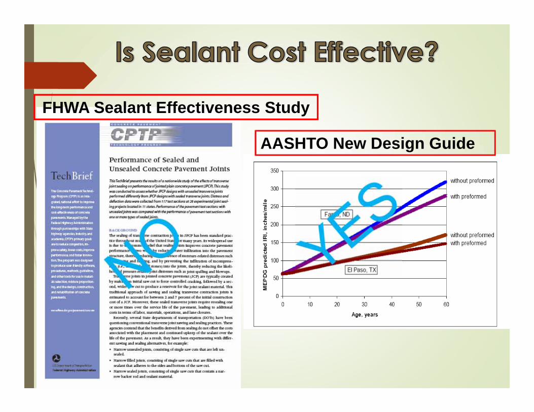
FHWA Sealant Effectiveness Study
AASHTO New Design Guide

A key outcome of this project is advancement of a mechanistic tool for analysis of specific combinations of traffic, climate, base materials, and sealant condition on subbase erosion and pavement performance.

0%10%20%30%40%50%60%70%80%90%
100%
Furnish and InstallCleaningReservoir CutInitial Cut
* ACPA Relative Cost Study


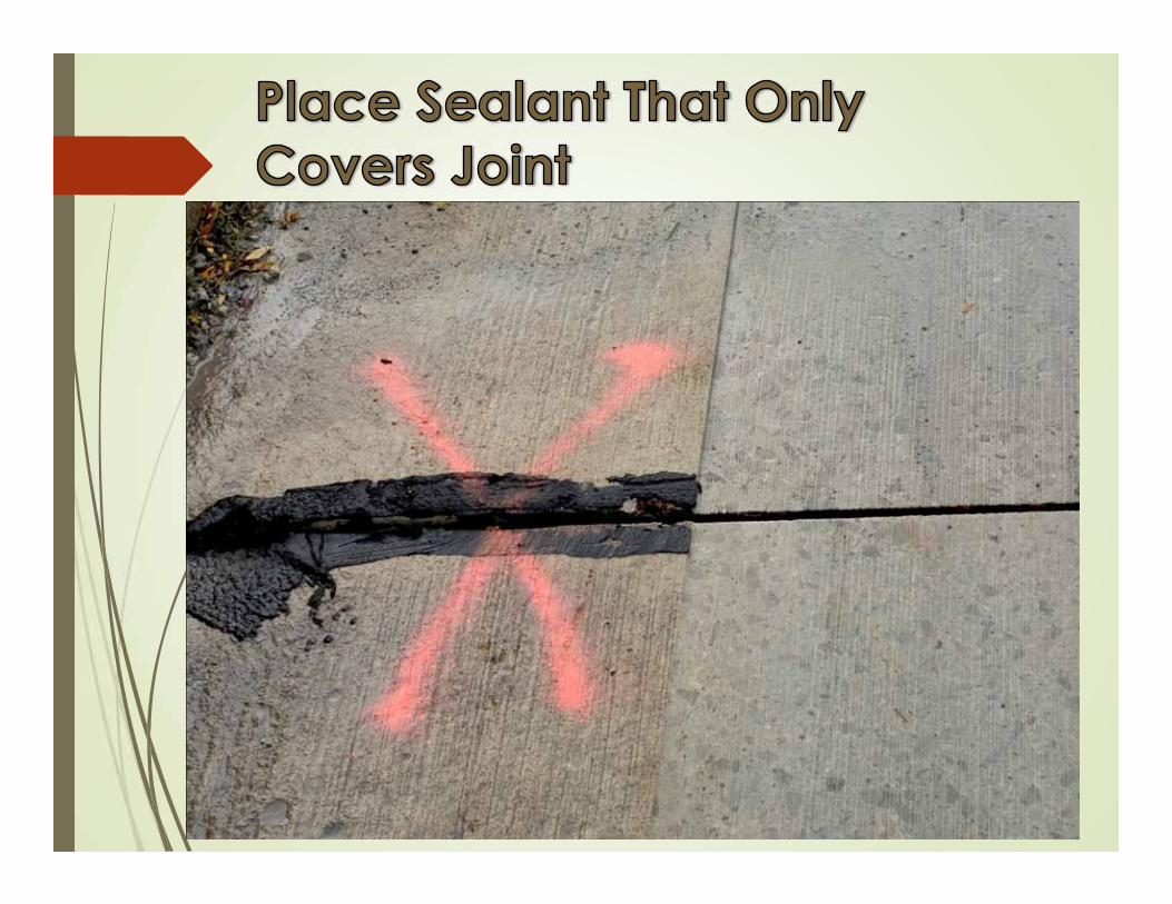
Prevents Incompressible from Lodging in the Joint — Slab Growth and
Blow Ups

Prevents Water from Entering the Subgrade:
-Prevents subgrade erosion-Voids beneath the slab PCCP


Joint Slap Adds 5 dBA to Overall Pavement Noise at 70 MPH


•Adhesive Failures•Cohesive Failures•% Damaged or Missing
When the Sealant is No Longer Serving its Intended Function


Crafco 221 = 5.4 – 9.8 yrsCrafco 231 = 6.4 – 9.5 yrsDow 888 SL = 12.8 yrsDow 888 = 13.9
232% to 348% Increase for Silicone


Old Concrete
New Concrete


Sealant Performance Depends On: Design Factors (See ACPA App Website)
Anticipated Movement Construction Schedule and Installation Conditions Required Performance Period Noise Considerations
Sealant Selection---Proper Design and Specification for Application
Joint Preparation---Clean, Dry, and Bondable Sealant installation
Silicone & Compression Seal Should be Recessed Hot Pour Should be Flush Filled Backer Rods Appropriate for Sealant Type Primer?

Hot Pour Sealants: 25% Extension
Silicone Sealants: 50% Compression to 100% Extension
Compression Seals: 15% min Compression to 50% Extension

• A= ¼” to 3/8”• B= ¼” to 3/8”• C= ¼” to ½”• C/B > 1
Backer Rod
Silicone
PCCP
Silicone
Backer Rod

*Joint Width 1/4” 3/8” 1/2” 5/8” 3/4” 7/8” 1” 1 1/8” 1 1/4” 1 3/8” 11/2”
Minimum Sealant Recess
1/4” 1/4” 5/16” 5/16” 3/8” 3/8” 3/8” 1/2” 1/2” 1/2” 1/2”
Backer Rod Diameter 1 3/8” 1/2” 5/8” 3/4” 7/8” 1” 1 1/4” 1 1/2” 1 1/2” 1 3/4” 2”
Sealant Bead Thickness 1/4” 1/4” 1/4” 5/16” 3/8” 7/16” 1/2” 1/2” 1/2” 1/2” 1/2”
Minimum Joint Saw/Reservoir Depth 1 1/8” 1 1/4” 1 1/2” 1 3/4” 1 7/8” 2” 2 3/8” 2 2 7/8” 3 1/8” 3 3/8”
Minimum Backer Rod Depth
1/2” 1/2” 5/8” 11/16” 3/4” 13/16” 7/8” 1” 1” 1” 1”
Estimated Usage Non-Sag
245 149 112 70 51 35 26 23 18 16 15
Estimated UsageSelf-leveling(ft./gal) 273 172 130 82 58 41 31 27 22 20 19
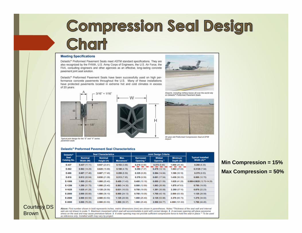
Courtesy DS Brown
Min Compression = 15%Max Compression = 50%


0
0.02
0.04
0.06
0.08
0.1
0.12
0.14
1 2 3 4 5 6 7 8 9 10 11 12
Crack Movem
ent (in)
Month of Construction
Phoenix, AZBismarck, NDSan Diego, CA


Material Selection Sealant Type
Hot Pour Silicone Compression Seals
Backer Rod Type (see SNS Group website)Open Cell Closed Cell Hybrid
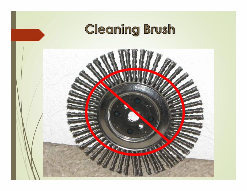
Preparation Sawing Cleaning
InstallationInspection
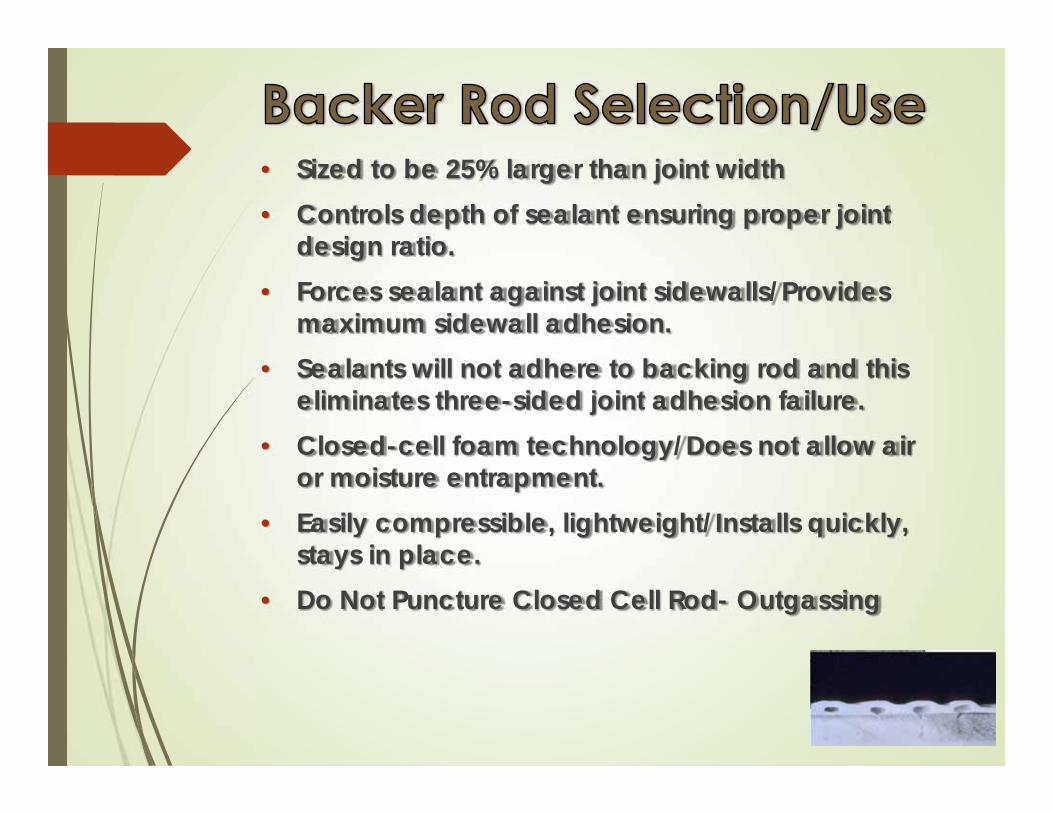
• Sized to be 25% larger than joint width• Controls depth of sealant ensuring proper joint
design ratio.• Forces sealant against joint sidewalls/Provides
maximum sidewall adhesion.• Sealants will not adhere to backing rod and this
eliminates three-sided joint adhesion failure.• Closed-cell foam technology/Does not allow air
or moisture entrapment.• Easily compressible, lightweight/Installs quickly,
stays in place.• Do Not Puncture Closed Cell Rod- Outgassing

Silicone Non Sag Self Leveling Rapid Cure
Hot Pour Standard Modulus Low Modulus
Compression Seal

Light GrayHorizontal or Vertical Application Low Modulus Requires Tooling Rehab or New Pavements Seals Small Spalled areas in Joint
Walls Tack Free in 25 to 90 mins. Full Cure through in 14 days

Dark Grey Horizontal Application
Only Ultra Low Modulus Neat Seal-No Tooling Rehab or New Pavements Tack Free in 3 hours max Full Cure through in 21
days 6% maximum grade AC/PC Joints ???


Drums-50 gals of Material5 Gallon Pails 29 oz. Tubes (6 per case)Store out of direct sun
Do not store in freezing
temperatures or above 90˚F.
Keep out of excessive humidity

•ASTM D-6690:
Type I - ASTM D1190
Type II - ASTM D 3405
Type III – Low Modulus
Type IV - Fed Spec SS-S-1401C
FAA P 605-ASTM D-6690
State Specifications

Modified Asphalt Based Sealants
2 to 15+ Year Life Cycle
Asphalt and Concrete Pavements
Different Grades available


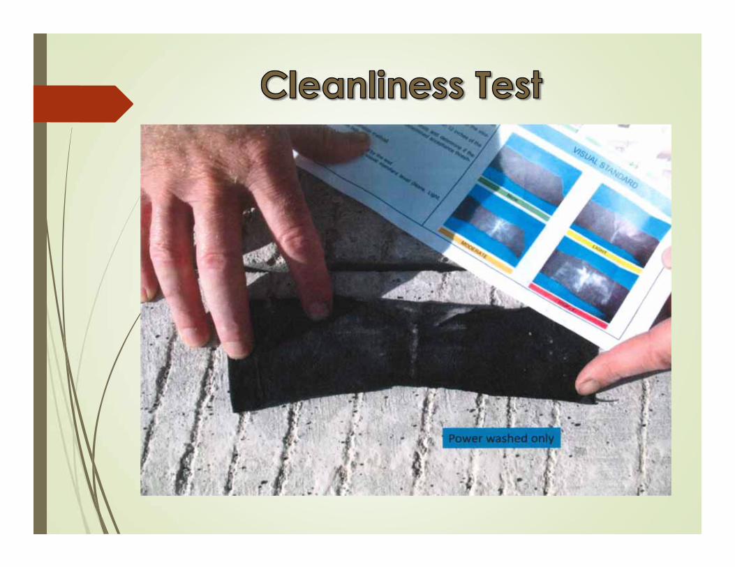
The pavement MUST be
clean and dry

Finger Test

Water blasting the joint after the saw cut operation is strongly recommended to remove any slurry from the joint.
Slurry remaining in the joint from sawing will dry on the walls. Silicone will then adhere to the slurry instead of the clean side wall.


After sawing, water blasting, drying, and sandblasting; the joint should be air blasted to remove any debris or sand remaining in the joint.


WJE Evaluations

3 in
2 in
1 in
ASTM D 1985 Concrete Block Sample
1 in
Pull Off test No. 1
Pull Off test No. 2
Bond test Area


Cold Rod/Hot RodBACKER ROD 25% Larger than Joint Closed Cell Backer Rod Do Not Puncture Backer Rod-
bubbling Do Not Stretch Backer Rod


Install Longitudinal Backer Rod First, Continuously Through the Transverse Joints and then Run Transverse Rod Continuously Across Pavement Pushing Down Longitudinal Rod at Intersection


40° F Minimum Pavement TemperaturesFlush Fill, Recessed or Over-band
Beveled Joint
Recessed Flush FilledFlush Filled
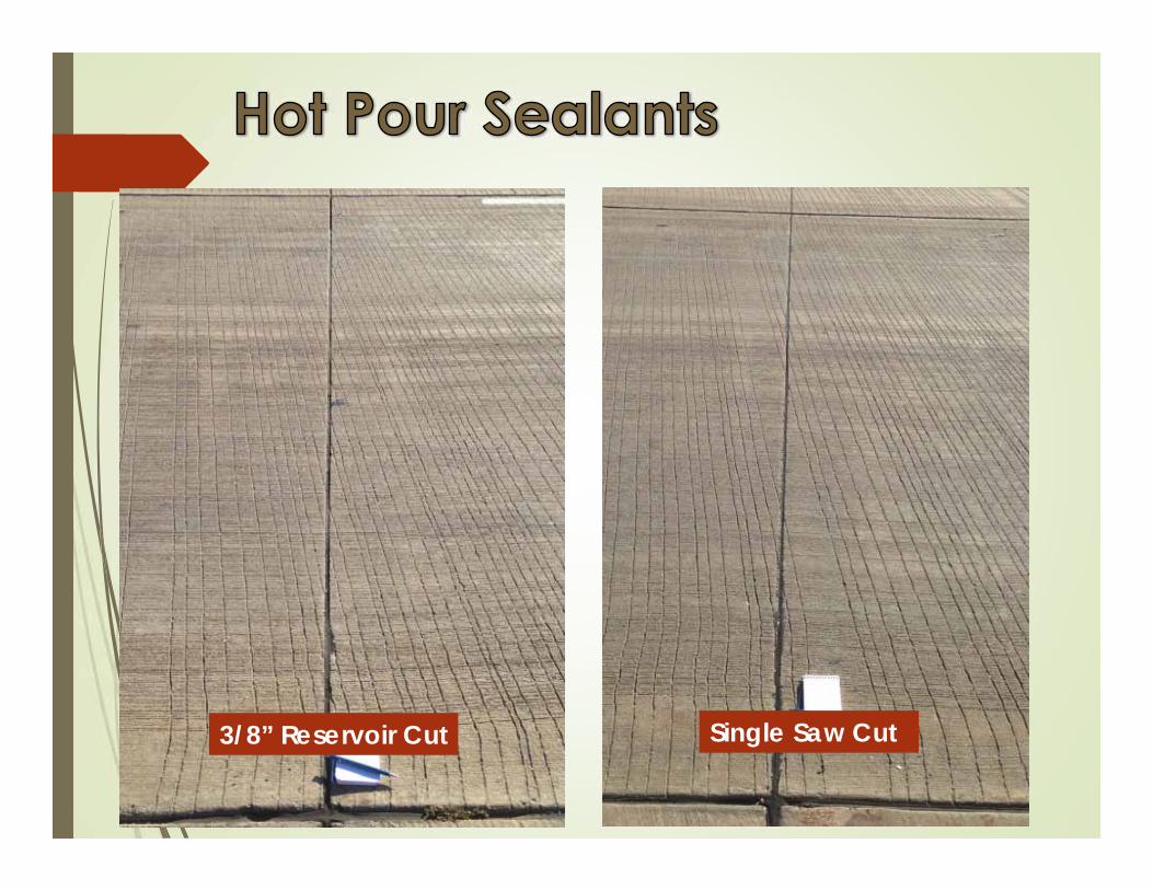
3/8” Reservoir Cut Single Saw Cut


Self LevelingNon Sag

40° F Minimum Pavement Temperatures1/8” Minimum RecessRequires Tooling


1. Make a knife cut horizontally across the silicone
2. Make a vertical cut approximately 3 inches long on each side of the joint
3. Hold the piece of silicone firmly and slowly pull at a 90° angle. If adhesion is proper, the silicone will not pull out of the joint, but will eventually tear cohesively


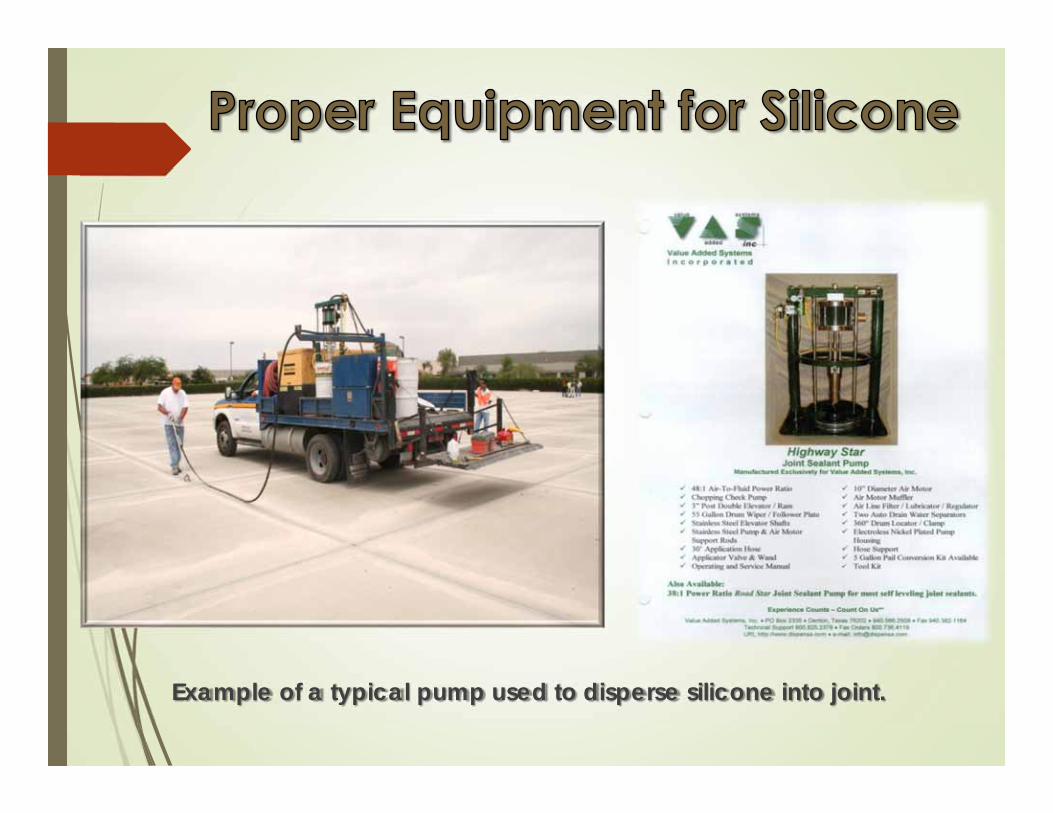
Example of a typical pump used to disperse silicone into joint.

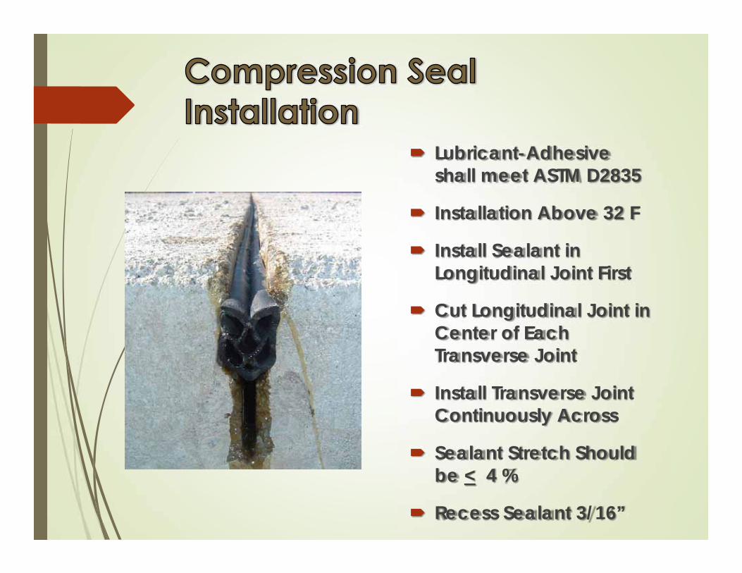
Lubricant-Adhesive shall meet ASTM D2835
Installation Above 32 F
Install Sealant in Longitudinal Joint First
Cut Longitudinal Joint in Center of Each Transverse Joint
Install Transverse Joint Continuously Across
Sealant Stretch Should be < 4 %
Recess Sealant 3/16”


Design Joint Sealant System for the Expected Joint Movements
Select a Joint Sealant Material and Backer Rod Appropriate for the Intended Purpose
Ensure Proper Cleaning and Preparation– Clean, Dry and Bondable
Inspect the Work and Verify its Acceptability


See Tech Brief• Design Joint Sealant System for the Expected Joint Movements
• Select a Joint Sealant Material and Backer Rod Appropriate for the Intended Purpose
• Ensure Proper Cleaning and Preparation– Clean, Dry and Bondable
• Inspect the Work and Verify its Acceptability