G81 Part 4 UDN 067 Rev 0
Page 1 of 50 Uncontrolled if Printed
UDN-DP-067
DESIGN AND PLANNING
UDN APPENDIX A FOR ENA ENGINEERING RECOMMENDATION G81-PART 4
FRAMEWORK FOR NEW INDUSTRIAL AND COMMERCIAL UNDERGROUND CONNECTIONS
Revision Date Changes Author Approval
0 07/03/17 First Issue Julie Tyrrell/Andy Billings Debbie Edgar
G81 Part 4 UDN 067 Rev 0
Page 2 of 50 Uncontrolled if Printed
CONTENTS
1.0 Introduction
2.0 Information required for design approval
3.0 Design and Planning
3.01 General
3.02 HV Network Design
3.03 Security of Supply
3.04 Location of Substations
3.05 Substation Earthing
3.05.1 General
3.05.2 Standalone GRP/Brick Substations
3.05.3 Integral and Basement Substations
3.05.4 HV Metered, Large LV and SNE Substations
3.05.5 Special Considerations
3.06 LV Network Design
3.06.1 Service Disconnections
3.07 Voltage Regulation
3.08 Voltage Unbalance
3.09 Earth Loop Impedance
3.10 Prospective Short Circuit Current
3.11 Cable Positioning and Duct Requirements
3.12 LV Cable Ratings
3.13 LV Connection Arrangements 23kVA to 1MVA
3.13.1 Arrangements for IDNO Adoption up to Meter 3.13.2 Arrangements for BNO/Private Networks
3.14 HV Customer Connections 3.15 Substation General 3.15.1 Substation Ventilation General 3.15.2 Freestanding Distribution Substation (GRP/Brick) 3.15.3 Integral/Basement Substations
Appendix 1 Substation Risk Assessment
Appendix 2 Large LV Arrangements
Appendix 3 Termination Drawings
3a 200A/400A Cut Outs and CT Metering
3b 600A Cut Out and CT Metering
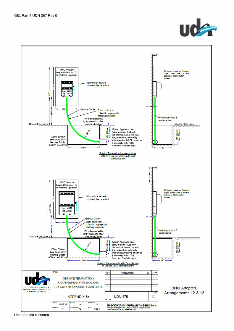
3c 200A/400A Cut Out for BNO Networks
3d 600A Cut Out for BNO Networks
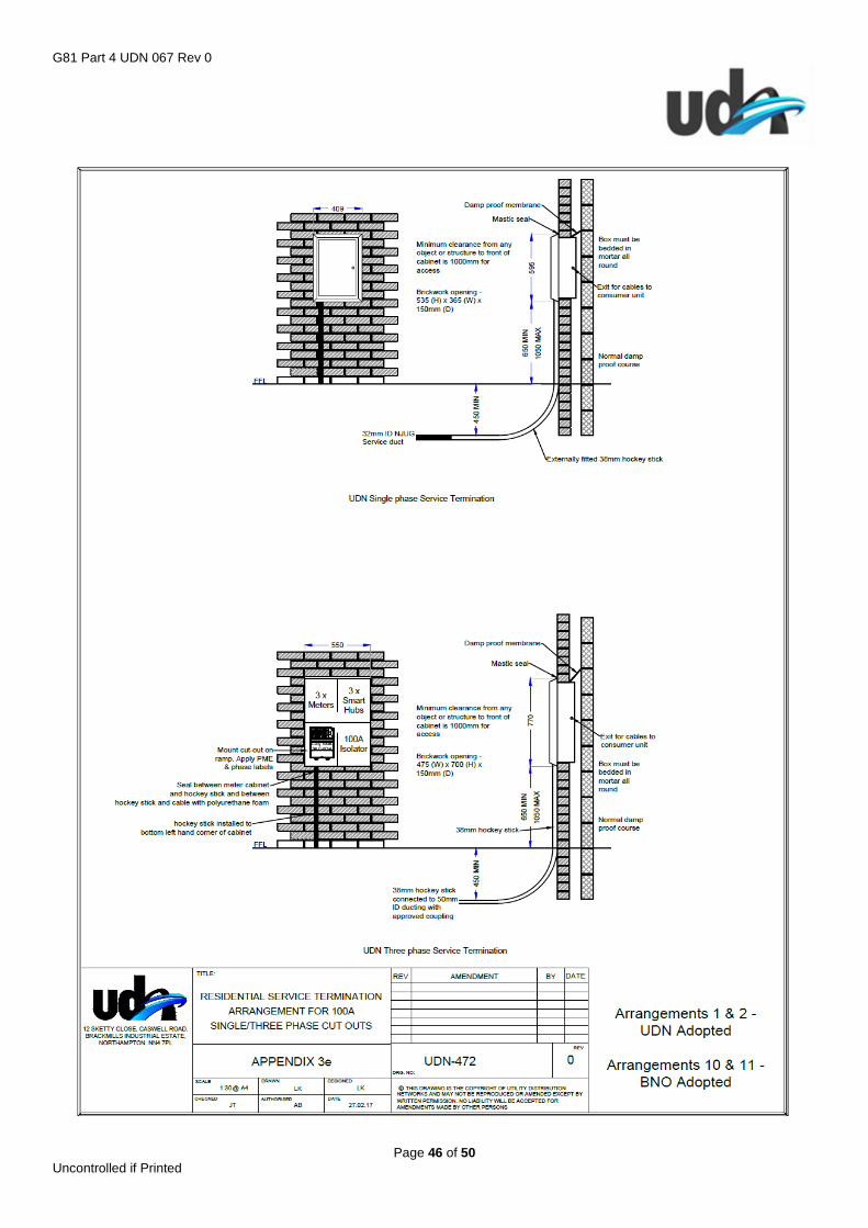
3e 1ph and 3ph Terminations and Meter Boxes
3f Service Termination Cubicles
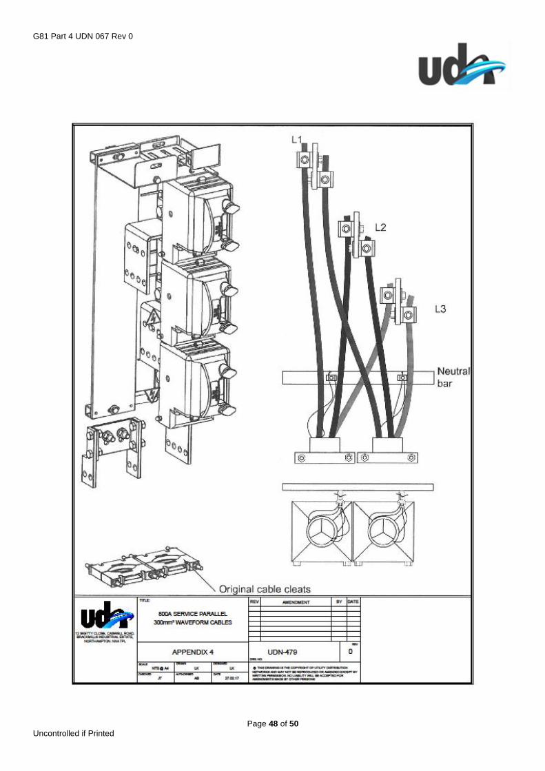
Appendix 4 800A Service – Parallel 300mm2 Waveform Cables
Appendix 5 800A Service – Parallel 185mm2 Bunched Cables
G81 Part 4 UDN 067 Rev 0
Page 3 of 50 Uncontrolled if Printed
1.0 INTRODUCTION
This document is an Appendix to Energy Networks Association (ENA) Engineering Recommendation (ER) G81-Part 1:
Design and Planning, “Framework for new low voltage housing development installations” and should be read in
conjunction with that document.
Other documents which must be read in conjunction with this appendix are: -
1. The National Framework Documents
2. The Adoption Agreement
3. UDN Appendices
4. Relevant Legislation
The principles of any design are to be agreed with UDN at the outset of the design process and should comply with
this document and the G81 documentation of the DNO where applicable. If further clarification is required, please
contact UDN directly before any site work commences.
The details of the proposed design are to be submitted to UDN for review and approval prior to construction. As an
alternative UDN would welcome discussions with NERs accredited applicants with a view to enabling them to approve
their own designs. In this situation UDN would reserve the right to undertake regular sample audits.
Where UDN requirements are not specified in this document ICP’s should plan to undertake any design work in
accordance with best industry practice, complying with all appropriate legislation, including those referred to in the
ENA G81 suite of documents. Copies of these documents may be obtained from the relevant issuing body.

G81 Part 4 UDN 067 Rev 0
Page 4 of 50 Uncontrolled if Printed
2.0 INFORMATION REQUIRED FOR DESIGN APPROVAL
Scaled General Arrangement drawing to include:
Cable routes, numbered joint positions, cross sections, substation locations, link box positions, meter
positions, landlords and commercial connections, unmetered connections and any temporary building
supplies.
On/off site boundary and location plan.
Extent of UDN network adoption
Phase of each single-phase connection.
Dimensions and details of terminations, cubicles, trenching arrangements and any other equipment to be
used on the project.
Tray work and containment sections.
Schematic to include:
All network ownership boundaries (DNO/UDN/BNO/PRIVATE).
Cable sizes, number of customers per feeder, fuse sizes at substation and termination positions, cut out and
CT sizes.
Volt drop % and earth loop resistance Ω at the end of each main and at each 3-phase cut-out position.
Details of voltage fluctuations as a result of any disturbing loads connected with associated data sheet for
each motor, this should be incorporated in the Windebut file.
Connection schedule detailing the number and type of customers per feeder, load per connection and total
load per feeder including any applied diversity.
Substation Drawings to include:
General Arrangement drawing including scaled plans, elevations and sections.
Earthing arrangement including layouts, sections and target value
Additional Details required:
Generation details including completed G83 and G59 applications.
A scaled Metering layout should also be provided for bulk metering and metering within riser cupboards.
Section 38/278 drawing showing roads to be adopted by local authority.
DNO connection details including; route of HV cable back to POC and HV single line diagram.
Scaled legal drawing including substation leasehold/freehold area, pedestrian and vehicle access routes and
any applicable easements for all cable routes that will be outside the future adopted highways. Landowner
and solicitor details must all be provided.
Design assessment including Health and Safety issues identified, including risk assessments (Appendix 1) for
substation locations and any special engineering difficulties, existing apparatus within the project works etc.
Earthing design detailing target impedance, step and touch potentials and any other considerations affecting
the earthing installation and equipment in the vicinity.

G81 Part 4 UDN 067 Rev 0
Page 5 of 50 Uncontrolled if Printed
3.0 DESIGN AND PLANNING
3.01 General
The design of new networks to be adopted by UDN shall comply with ENA documentation, UDN standards and all
relevant legislation, including any updates and publications in keeping with good industry practice.
3.02 HV Network Design
The high voltage network shall utilise the Host DNO standard design, including the type of switchgear, underground
cable and conductor sizes where the POC is provided by the Host DNO.
Where the HV POC is provided by UDN the design will utilise the standard UDN design, including the type of
switchgear, underground cable and conductor size.
Summer (Distribution) Current Ratings of 11kV Single Core (or Triplex) Cables are based on the following parameters:
Standard Depth Agricultural/Landscaped Depth
Based on Pirelli data sheets
Max depth of Lay 0.6m 1.0m
Soil Thermal Resistivity 1.2⁰ C m/W 1.2⁰ C m/W
Ground Ambient Temperature 150C 15⁰ C
Air Ambient Temperature 250C 25⁰ C
Maximum Conductor Temperature 900C 90⁰ C
Cyclic Enhancement Factor 1.13 1.13
See Drawing UDN 481 for typical cable trench cross sections.
Size and Type of Conductor
Summer Distribution Current Rating in Amps
Standard Depth Agricultural/Landscape Depth In Air
In Ground In Duct In Ground In Duct
300mm2 Cu 678 633 657 614 760
95mm2 Al 283 288 274 279 300
185mm2 Al 407 396 394 384 435
300mm2 Al 537 514 520 498 600
Duct sections less than 15m can be treated as direct laid for cable rating purposes, if the percentage ducted for the
cable section is less than 40%.
Derating factors for multiple cables laid in horizontal arrangement.
Number of 11kV circuits Spacing of Circuits (m)
0.15 0.2 0.3
2 0.81 0.82 0.85
3 0.71 0.73 0.76
4 0.65 0.67 0.72
5 0.61 0.63 0.68
Standard transformer sizes that are accepted include 315kVA; 500kVA; 800kVA; 1000kVA. All transformers will be
Eco Loss (Tier 1).
Transformers above 1000kVA can be used to supply single commercial/industrial connections subject to individual
project approval by UDN and the client accepting that the arrangement will not comply with P2/6.
UDN will not adopt any overhead networks.

G81 Part 4 UDN 067 Rev 0
Page 6 of 50 Uncontrolled if Printed
3.03 Security of Supply
UDN’s preference is for all substations to be looped into the existing HV network so that a connection is available with
a switched alternative to provide additional security of supply and keep customer minutes lost to a minimum, unless
otherwise agreed at the design stage.
In exceptional circumstances, as a minimum, connections must meet the requirements of Engineering
Recommendation P2/6- security of supply. For large developments where the network is to be extended in phases
over a prolonged period, the network must be designed to ensure that P2/6 requirements are met at the completion of
each phase.
LV Back-Feeds must be considered where more than one substation is installed within a development, this will be
designed to provide capacity to support 30% of the load fed from the de-energised substation. Where this is not
possible facility for locating, and connecting a generator must be provided.
3.04 Location of Substations
All substations shall be designed as centrally to the development load as possible, considering future developments
which will also be fed from the same substation. Where UDN substations are located outside the perimeter of the
development UDN reserve the right to review the AV offered in lieu of the increased losses anticipated on the LV
network.
GRP substations should not be located any closer than 7m from any property, this can be reduced to 3m if the
substation is constructed in Brick.
Integral substations should not be located directly against working/living areas as a precaution against high EMF’s (in
accordance with ENA ER G92), this will also mitigate issues such as access, noise, vibration etc. Where the
developer wishes to contravene these regulations, they must commission an environmental study to demonstrate
EMF levels anticipated after construction are below current required values, for UDN to hold on file for the lifetime of
the asset.
The substation must have 24-hour unimpeded pedestrian and vehicle access at all times from the highway.
To comply with ESQCR a risk assessment (Appendix 1) should also be undertaken which must consider the following:
Interference
Environmental Issues
Noise Pollution/Vibration
Risk of Flooding
Risk of Vandalism/vehicle damage
Unauthorised Access
Surrounding Area
Selection of Doors/Locks
G81 Part 4 UDN 067 Rev 0
Page 7 of 50 Uncontrolled if Printed
3.05 Substation Earthing
3.05.1 General
Substation earthing designs shall follow the guidelines set out in ENATS 41-24 and all relevant British Standards
including (BS7430 & BS EN 50522) and ESQCR Regulations.
Where the host DNO provide the POC, then the earthing design shall follow the local DNO designs. The design shall
include the following information, which will be provided by the Host DNO: -
Is the Source Substation ‘Hot’ or Cold’?*
Is the circuit from the source substation all cable, or does it include OHL?
Fault Clearance time at Source Substation.
Fault level at POC.
*If the source substation is ‘hot’ then transferred touch potentials to the local substation need to be assessed.
3.05.2 Standalone GRP/Brick Substations
For typical commercial/industrial developments where a standalone GRP or Brick substation is used, the design
drawings shall include supporting information including; calculations (EPR, target resistance - before and after
connection); evidence to support the design and any additional earthing required to maintain a ‘cold’ site. If the site is
classified as a ‘hot’ site, the design will also include the separation distances between the HV and LV earthing
systems and associated calculation.
Note: where the site is ‘cold’ and the fault clearance time exceeds 1 second then HV and LV earth systems may still
need to be separated to comply with BS EN50522. See table 2 in section 3.05.4 where ‘F’ will equal 2.
3.05.3 Integral & Basement Substations
Integral and basement substations where the standard Host DNO arrangements cannot be achieved in full may
require a bespoke earthing design. The integral earthing arrangement, layout and conductor sizes shall still follow the
requirements of the host DNO, with the bespoke earthing design ‘dovetailed’ to provide a complete design. The details
of the bespoke earthing design will need to be submitted to the host DNO and UDN for approval, and shall include
supporting information, calculations (EPR, target resistance – before and after connection).
Note: where the site is ‘cold’ and the fault clearance time exceeds 1 second then HV and LV earth systems may still
need to be separated to comply with BS EN50522. See table 2 in section 3.05.4 where ‘F’ will equal 2.
3.05.4 HV Metered Customer Substations, Large LV Customers from a Single Substation or
Substations providing exclusively SNE Networks
HV metered Customer substation, the customer will be responsible for designing and installing an earthing system for
their installation/network to the relevant standards and legislation. The customers earthing system can be connected
via removable links to the HV earth, where supporting information, calculations (EPR, target resistance - before and
after connection), evidence has been provided for the HV earthing system to confirm the EPR is safe to allow the HV
& LV Earth to be connected. (See extract from BS EN 50522 below).
Where single Large LV customers are connected from a single freestanding external substation, the customer does
not have to undertake an earthing design. The below method of determining the EPR shall be used to confirm that the
HV & LV earths can be combined at the external substation position. The design shall include supporting information,
calculations (EPR, target resistance – before and after connection).
Substations providing exclusively SNE networks, (generally integral substations in blocks of flats), may require a
bespoke earthing design. The below method of determining the EPR shall be used to confirm that the HV & LV earths
can be combined. The design shall include supporting information, calculations (EPR, target resistance – before and
after connection).
G81 Part 4 UDN 067 Rev 0
Page 8 of 50 Uncontrolled if Printed
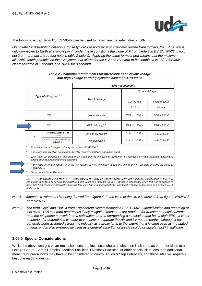
The following extract from BS EN 50522 can be used to determine the safe value of EPR.
On private LV distribution networks, those typically associated with customer owned transformers, the LV neutral is
only connected to Earth at a single point. Under these conditions the value of F from table 2 in BS EN 50522 is now
not 2 or more, but 1 (see foot note in table 2 below). Applying the same formula now means that the maximum
allowable touch potential on the LV system that allows for the HV and LV earth to be combined is 233 V for fault
clearance time of 1 second, and 162 V for 3 seconds.
Note1: - footnote ‘e ‘refers to UTP being derived from figure 4. In the case of the UK it is derived from figures NA2/NA3
or table NA1.
Note 2: - The term ‘Cold’ and ‘Hot’ is from Engineering Recommendation S36-1:2007 – 'Identification and recording of 'hot sites'. This standard determines if any mitigation measures are required for transfer potential hazards onto the telephone network from a substation or area surrounding a substation that has a high EPR. It is not a criterion for determining whether to combine or separate the HV and LV neutral earths, although it has generally been accepted across the industry as a proxy for it, to the extent that it is often used as the stated criteria, and is also erroneously used as a general assertion of a safe (‘cold’) or unsafe (‘hot’) installation.
3.05.5 Special Considerations
Whilst the above designs cover most situations and locations, where a substation is situated as part of or close to a
Leisure Centre, Sports Complex, Medical Facilities, Livestock Facilities, or other special situations then additional
measure or precautions may have to be considered to control Touch & Step Potentials, and these sites will require a
bespoke earthing design.

G81 Part 4 UDN 067 Rev 0
Page 9 of 50 Uncontrolled if Printed
3.06 UDN adopted LV Network Design
The recommended design tool Windebut, provided by EA Technology shall be used, other software packages must be
approved by UDN prior to commencement of the design.
UDN will adopt CNE and where appropriate SNE low voltage cables; standard size mains cables are
95mm2/185mm2/300mm2 as specified in our latest G81 Part 5 Materials List and used in accordance with the standard
arrangements. Service cables for 100A 3 phase service shall be 35mm2 and be no more than 30m.
LV Back-Feeds must be considered where more than one substation is installed within a development, this will be
designed to provide capacity to support 30% of the load, or supporting essential supplies, fed from the de-energised
substation. Where this is not possible facility for locating, and connecting a generator must be provided.
Secondary supplies can be provided by UDN. Where this is from an LV POC external to the building then a link box
will be required in an accessible position within a footway.
Fire fighter’s supplies cannot be accommodated as they do not comply with BS9999, however secondary supplies can
be provided from alternative network connections or from the same substation using a diverse route, subject to
agreement from the client and developer.
LV networks shall generally be designed as a PME system, in accordance with the latest guidance in ENA ER G12/4.
Services shall be provided with a PME earth terminal, where it is appropriate and safe. Some situations and properties
are unsafe and unsuitable for the provision of a PME earth terminal, for full details please refer to ENA G12/4.
Each LV main shall have an earth rod installed at the stop end joint, in addition branch or spur mains cables that have
4 or more services and/or are greater than 40mtrs in length will also have earth rods installed at the stop end. Where
the end of the main interconnects with an LV cable from another substation via a link box there is no need to install an
earth rod.
Where large LV services above 100A are installed into buildings, a minimum 70mm2 green/yellow earth wire will be
brought out and an earth rod installed as close to the entry point as possible.
Steel Framed buildings or buildings with shared metallic services, should not be provided with multiple PME earth
terminals. Where multiple services are required into a steel framed building, or with shared metallic services, then
services should be provided using SNE cable.
A metallic framework may consist of: -
Steel Frame construction
Continuous metal service (waste or supply) pipes within a property
Communal metal ducting, such as steel ducts
Reinforced concrete constructions, where the rebar is exposed or bonded to
External metal cladding
Earth bonding between properties
It should be assumed that buildings that share any framework or services have or will have a shared metallic
framework or shared metallic services either as designed or fortuitously unless it can be adequately demonstrated by
the building owner or developer.
For BNO networks UDN require copies of the network schematics, up to each meter position, for their records,
however for repair purposes they would be classed as a single customer.
3.06.1 Service Disconnections
Where services are to be disconnected (such as Temp Building Supplies), these shall be ‘stop’ ended in the public
footway. The ICP will complete a Service Record Card and send to UDN within 5 working days.
G81 Part 4 UDN 067 Rev 0
Page 10 of 50 Uncontrolled if Printed
3.07 Voltage Regulation
The Maximum Voltage at the distribution system Exit Point shall NOT exceed 10% of the nominal voltage of 230V (i.e.
253V) and the minimum voltage at the distribution system Exit Point shall NOT be less than -6% of nominal voltage of
230V (i.e. 216V).
The maximum voltage regulation in any service cable shall not exceed 2%.
Disturbing loads must comply with ER P28, the maximum voltage dip allowed for frequent starting is 1% and for
infrequent starting is 3% at the point of common coupling. Details of all disturbing loads to be provided on the
Windebut file and supported with a data sheet.
3.08 Voltage Unbalance
The maximum voltage unbalance should comply with ER P29 and shall not exceed 10%.
3.09 Earth Loop Impedance
Windebut will select fuse sizes in accordance with the load on each feeder and considering the current carrying
capacity of the mains cable.
The Phase-Neutral Loop Impedance at the service position must not exceed 350 milliohms. This also applies to
unmetered connections.
3.10 Prospective Short Circuit Current
Design Maximum 1ph 230V is 16kA
Design Maximum 3ph 400V is 25kA
Networks within the UKPN LPN CHLDZ area will need to be designed to 50kA, clarification should be sort from UKPN
on the maximum design fault level.
Further guidance is available in ENA ER P25 and P26
3.11 Cable Positioning and Duct Requirements
All cables should be located and installed in accordance with the National Joint Utility Group Publication NJUG volume
2 and the UDN Installation and Records Appendix.
Mains cables should not pass under buildings and should be laid in ground to be adopted by the local authority.
Where this is not practical then an ‘Easement’ will be required for those sections of cable affected.
All road crossings shall be ducted with at least one spare duct per crossing, per voltage level.
Any required joints should be located beneath the footpath and not in the carriageway.
Where ducts are installed within concrete then they will be steel pipe, to be medium quality, screwed, complying with
BS1387:1985, with a spare per cable.
Ducts shall be to ENATS 12-24 Black Rigiduct marked as ‘Electric Cable Duct’
LV and HV Warning tape shall be to ENATS 12-23, marked with Utility Distribution Networks in accordance with UDN
G81 Materials Specification and placed centrally over each cable, duct and joint.
G81 Part 4 UDN 067 Rev 0
Page 11 of 50 Uncontrolled if Printed
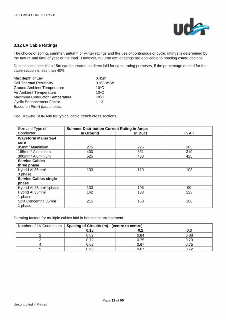
3.12 LV Cable Ratings
The choice of spring, summer, autumn or winter ratings and the use of continuous or cyclic ratings is determined by
the nature and time of year or the load. However, autumn cyclic ratings are applicable to housing estate designs.
Duct sections less than 15m can be treated as direct laid for cable rating purposes, if the percentage ducted for the
cable section is less than 40%.
Max depth of Lay 0.45m
Soil Thermal Resistivity 0.90C m/W
Ground Ambient Temperature 100C
Air Ambient Temperature 100C
Maximum Conductor Temperature 700C
Cyclic Enhancement Factor 1.13
Based on Pirelli data sheets.
See Drawing UDN 480 for typical cable trench cross sections.
Size and Type of Conductor
Summer Distribution Current Rating in Amps
In Ground In Duct In Air
Waveform Mains 3&4 core
95mm2 Aluminium 275 225 205
185mm2 Aluminium 400 331 310
300mm2 Aluminium 525 438 425
Service Cables three phase
Hybrid Al 35mm2
3 phase 133 110 103
Service Cables single phase
Hybrid Al 25mm2 1phase 133 108 99
Hybrid Al 35mm2 1 phase
162 133 123
Split Concentric 35mm2
1 phase 215 158 166
Derating factors for multiple cables laid in horizontal arrangement.
Number of LV Conductors Spacing of Circuits (m) - (centre to centre)
0.15 0.2 0.3
2 0.82 0.84 0.88
3 0.72 0.75 0.79
4 0.62 0.67 0.75
5 0.63 0.67 0.72
G81 Part 4 UDN 067 Rev 0
Page 12 of 50 Uncontrolled if Printed
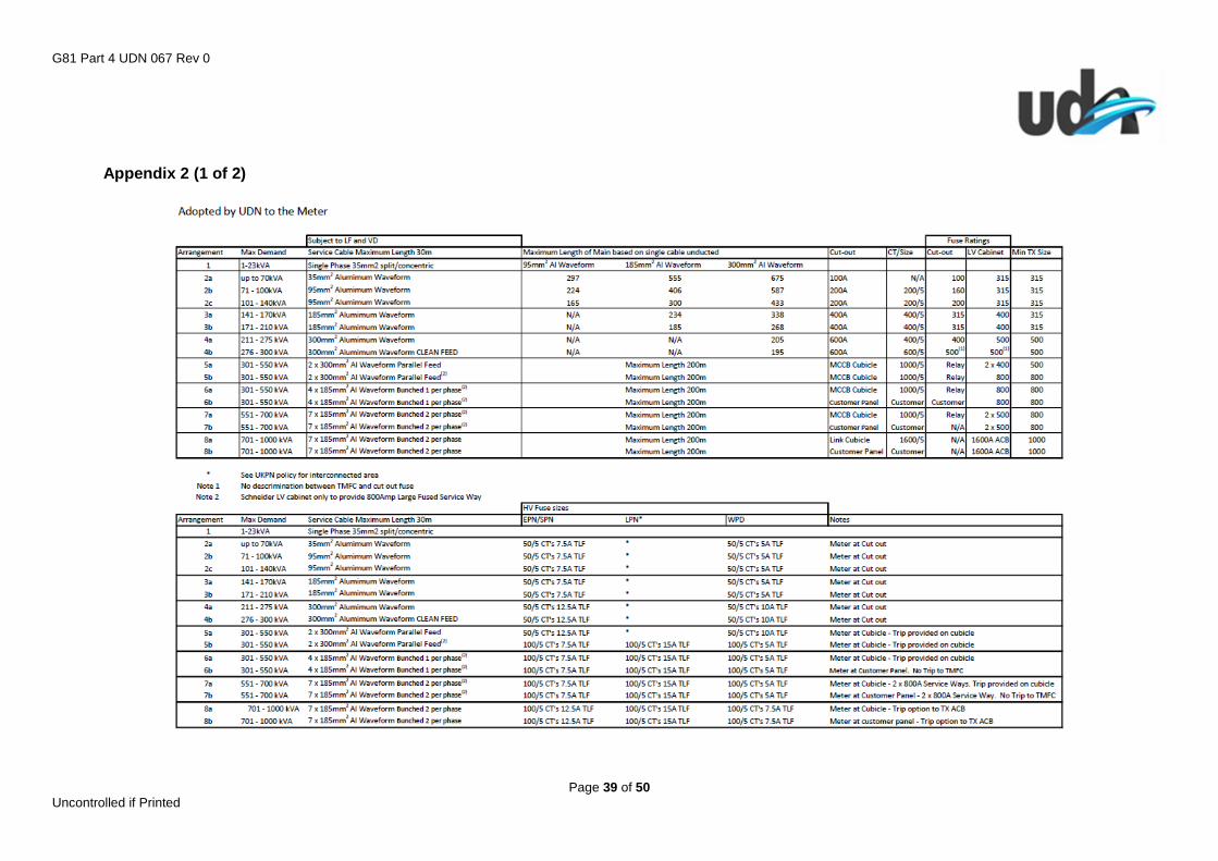
3.13 LV Connection Arrangements 23kVA to 1MVA – Appendix 2
3.131 Arrangements for IDNO Adoption Up to the Meter
See Appendices for summary of arrangements and termination requirements.
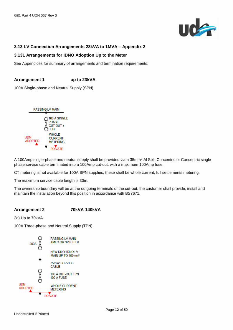
Arrangement 1 up to 23kVA
100A Single-phase and Neutral Supply (SPN)
A 100Amp single-phase and neutral supply shall be provided via a 35mm2 Al Split Concentric or Concentric single
phase service cable terminated into a 100Amp cut-out, with a maximum 100Amp fuse.
CT metering is not available for 100A SPN supplies, these shall be whole current, full settlements metering.
The maximum service cable length is 30m.
The ownership boundary will be at the outgoing terminals of the cut-out, the customer shall provide, install and
maintain the installation beyond this position in accordance with BS7671.
Arrangement 2 70kVA-140kVA
2a) Up to 70kVA
100A Three-phase and Neutral Supply (TPN)
G81 Part 4 UDN 067 Rev 0
Page 13 of 50 Uncontrolled if Printed
A 100Amp three-phase and neutral supply shall be provided via a 35mm2 three phase Al Concentric service cable
terminated into a 100Amp TPN cut-out, with a maximum 100Amp fuse.
CT metering is not available for 100A TPN supplies, these shall be whole current, full settlements metering.
The maximum service cable length is 30m, guidance on the length of LV main is detailed in Appendix 2. Space
requirements are detailed in the termination drawings.
The ownership boundary will be at the outgoing terminals of the cut-out, the customer shall provide, install and
maintain the installation beyond this position in accordance with BS7671. Armoured or tri-rated cables shall not be
terminated into the 100A cut-out.
2b) 71 – 100kVA
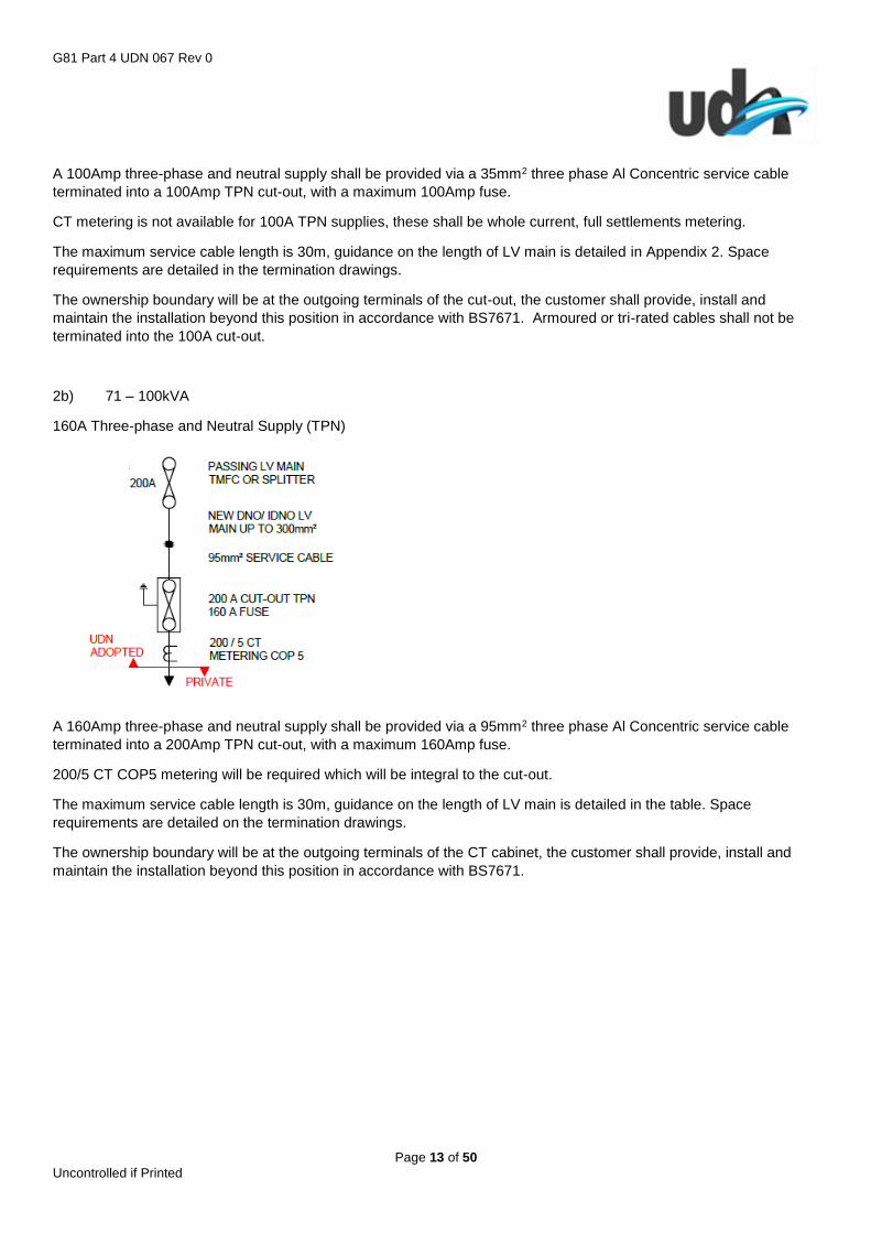
160A Three-phase and Neutral Supply (TPN)
A 160Amp three-phase and neutral supply shall be provided via a 95mm2 three phase Al Concentric service cable
terminated into a 200Amp TPN cut-out, with a maximum 160Amp fuse.
200/5 CT COP5 metering will be required which will be integral to the cut-out.
The maximum service cable length is 30m, guidance on the length of LV main is detailed in the table. Space
requirements are detailed on the termination drawings.
The ownership boundary will be at the outgoing terminals of the CT cabinet, the customer shall provide, install and
maintain the installation beyond this position in accordance with BS7671.

G81 Part 4 UDN 067 Rev 0
Page 14 of 50 Uncontrolled if Printed
2c) 101 – 140kVA
200A Three-phase and Neutral Supply (TPN)
A 200Amp three-phase and neutral supply shall be provided via a 95mm2 three phase Al Concentric service cable
terminated into a 200Amp TPN cut-out, with a maximum 200Amp fuse.
200/5 CT COP5 metering will be required which will be integral to the cut-out.
The maximum service cable length is 30m, guidance on the length of LV main is detailed in the table. Space
requirements are detailed on the termination drawings (Appendix 3).
The ownership boundary will be at the outgoing terminals of the CT cabinet, the customer shall provide, install and
maintain the installation beyond this position in accordance with BS7671.
Arrangement 3 141kVA-210kVA
3a) 141 – 170kVA
3b) 171 – 210kVA
315A Three-phase and Neutral Supply (TPN)
A 315Amp three-phase and neutral supply shall be provided via a 185mm2 three phase Al Concentric cable
terminated into a 400Amp TPN cut-out, with a maximum 315Amp fuse.
G81 Part 4 UDN 067 Rev 0
Page 15 of 50 Uncontrolled if Printed
400/5 CT COP5 metering will be required which will be integral to the cut-out.
The maximum cable lengths for option a) and option b) are detailed in Appendix 2, space requirements are detailed on
the termination drawings (Appendix 3).
The ownership boundary will be at the outgoing terminals of the CT cabinet, the customer shall provide, install and
maintain the installation beyond this position in accordance with BS7671.
Arrangement 4 211kVA-300kVA
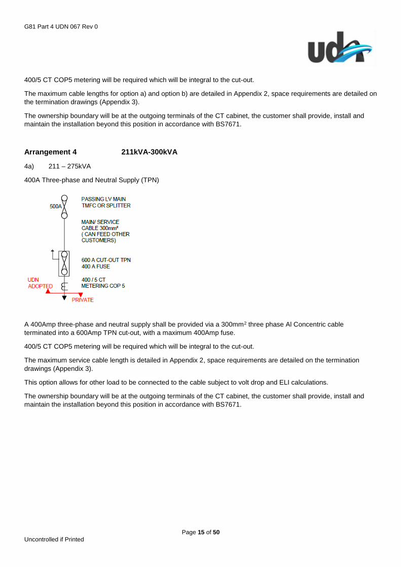
4a) 211 – 275kVA
400A Three-phase and Neutral Supply (TPN)
A 400Amp three-phase and neutral supply shall be provided via a 300mm2 three phase Al Concentric cable
terminated into a 600Amp TPN cut-out, with a maximum 400Amp fuse.
400/5 CT COP5 metering will be required which will be integral to the cut-out.
The maximum service cable length is detailed in Appendix 2, space requirements are detailed on the termination
drawings (Appendix 3).
This option allows for other load to be connected to the cable subject to volt drop and ELI calculations.
The ownership boundary will be at the outgoing terminals of the CT cabinet, the customer shall provide, install and
maintain the installation beyond this position in accordance with BS7671.
G81 Part 4 UDN 067 Rev 0
Page 16 of 50 Uncontrolled if Printed
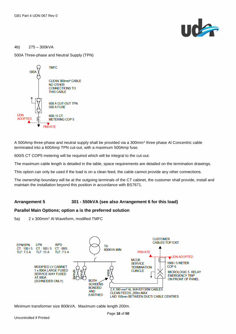
4b) 275 – 300kVA
500A Three-phase and Neutral Supply (TPN)
A 500Amp three-phase and neutral supply shall be provided via a 300mm2 three phase Al Concentric cable
terminated into a 600Amp TPN cut-out, with a maximum 500Amp fuse.
600/5 CT COP5 metering will be required which will be integral to the cut-out.
The maximum cable length is detailed in the table, space requirements are detailed on the termination drawings.
This option can only be used if the load is on a clean feed, the cable cannot provide any other connections.
The ownership boundary will be at the outgoing terminals of the CT cabinet, the customer shall provide, install and
maintain the installation beyond this position in accordance with BS7671.
Arrangement 5 301 - 550kVA (see also Arrangement 6 for this load)
Parallel Main Options; option a is the preferred solution
5a) 2 x 300mm2 Al Waveform, modified TMFC
Minimum transformer size 800kVA. Maximum cable length 200m.
G81 Part 4 UDN 067 Rev 0
Page 17 of 50 Uncontrolled if Printed
Two 300mm2 cables fed from a single 800Amp LV way in the TMFC fused at 800Amps; these cables run into a
termination cubicle at the customers’ premises. The termination cubicle includes 1000/5 removable CT’s for COP5
metering; a micrologic 5 relay and a trip facility. See Appendix 4 (Drawing UDN 479) for termination arrangement in
TMFC.
Protection Settings for the termination cubicle are as follows: -
Up to 400kVA Up to 550kVA
In = 1000A In = 1000A
Ir = 600A (0.6 x In) Ir = 800A (0.8 x In)
tr = 2s @ 6 x Ir tr = 2s @ 6 x Ir
Isd = 1500A (2.5 x Ir) Isd = 2000 (2.5 x Ir)
tsd = 0s, I2t off tsd = 0s, I2t off
Ii = 4000A (4 x In) Ii = 4000A (4 x In)
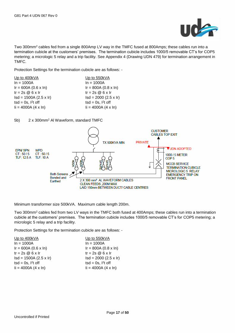
5b) 2 x 300mm2 Al Waveform, standard TMFC
Minimum transformer size 500kVA. Maximum cable length 200m.
Two 300mm2 cables fed from two LV ways in the TMFC both fused at 400Amps; these cables run into a termination
cubicle at the customers’ premises. The termination cubicle includes 1000/5 removable CT’s for COP5 metering; a
micrologic 5 relay and a trip facility.
Protection Settings for the termination cubicle are as follows: -
Up to 400kVA Up to 550kVA
In = 1000A In = 1000A
Ir = 600A (0.6 x In) Ir = 800A (0.8 x In)
tr = 2s @ 6 x Ir tr = 2s @ 6 x Ir
Isd = 1500A (2.5 x Ir) Isd = 2000 (2.5 x Ir)
tsd = 0s, I2t off tsd = 0s, I2t off
Ii = 4000A (4 x In) Ii = 4000A (4 x In)
G81 Part 4 UDN 067 Rev 0
Page 18 of 50 Uncontrolled if Printed
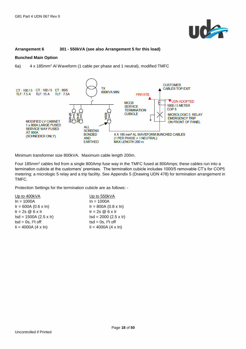
Arrangement 6 301 - 550kVA (see also Arrangement 5 for this load)
Bunched Main Option
6a) 4 x 185mm2 Al Waveform (1 cable per phase and 1 neutral), modified TMFC
Minimum transformer size 800kVA. Maximum cable length 200m.
Four 185mm2 cables fed from a single 800Amp fuse way in the TMFC fused at 800Amps; these cables run into a
termination cubicle at the customers’ premises. The termination cubicle includes 1000/5 removable CT’s for COP5
metering; a micrologic 5 relay and a trip facility. See Appendix 5 (Drawing UDN 478) for termination arrangement in
TMFC.
Protection Settings for the termination cubicle are as follows: -
Up to 400kVA Up to 550kVA
In = 1000A In = 1000A
Ir = 600A (0.6 x In) Ir = 800A (0.8 x In)
tr = 2s @ 6 x Ir tr = 2s @ 6 x Ir
Isd = 1500A (2.5 x Ir) Isd = 2000 (2.5 x Ir)
tsd = 0s, I2t off tsd = 0s, I2t off
Ii = 4000A (4 x In) Ii = 4000A (4 x In)

G81 Part 4 UDN 067 Rev 0
Page 19 of 50 Uncontrolled if Printed
6b) 4 x 185mm2 Al Waveform (1 cable per phase and 1 neutral), modified TMFC
This option is identical to Arrangement 4a (above), but with cables terminating into the customers’ own panel.
Customers panel to allow termination of 4 x 185mm2 Al Waveform cables and to incorporate suitable size settlements
class removable CT’s for COP5 metering; and a main isolator. Remote tripping of the supply from the TMFC is not
available. See Appendix 5 (Drawing UDN 478) for termination arrangement in TMFC.
Arrangement 7 551 – 700kVA
7a) 7 x 185mm2 Al Waveform (2 cables per phase and 1 neutral), modified TMFC
Minimum transformer size 800kVA. Maximum cable length 200m.
Seven 185mm2 cables fed from two 800Amp fuse ways in the TMFC each fused at 500Amps; these cables run into a
termination cubicle at the customers’ premises. The termination cubicle includes 1000/5 removable CT’s for COP5
metering; a micrologic 5 relay and a trip facility.
Protection Settings for the termination cubicle are as follows: -
Up to 600kVA Up to 700kVA
In = 1000A In = 1000A
Ir = 900A (0.9 x In) Ir = 1000A (0.9 x In)
tr = 2s @ 6 x Ir tr = 1s @ 6 x Ir
Isd = 2250A (2.5 x Ir) Isd = 2000 (2 x Ir)
tsd = 0s, I2t off tsd = 0s, I2t off
Ii = 4000A (4 x In) Ii = 4000A (4 xIn)

G81 Part 4 UDN 067 Rev 0
Page 20 of 50 Uncontrolled if Printed
7b) 7 x 185mm2 Al Waveform (1 cable per phase and 1 neutral), modified TMFC
This option is identical to Arrangement 7a (above), but with cables terminating into the customers’ own panel.
Customers panel to allow termination of 7 x 185mm2 Al Waveform cables and to incorporate suitable size settlements
class removable CT’s for COP5 metering; and a main isolator. Remote tripping of the supply from the TMFC is not
available.
Arrangement 8 701 - 1000kVA
8a) 7 x 185mm2 Al Waveform (2 cables per phase and 2 neutral), TMFC to incorporate ACB
Minimum transformer size 800kVA. Maximum cable length 200m.
Seven 185mm2 cables fed from a 1600Amp ACB in the TMFC; these cables run into a link cubicle at the customers’
premises. The link cubicle includes 1600/5 removable CT’s for COP5 metering; a trip option must be offered to the
client to remotely trip the TMFC ACB.
Protection Settings for ACB are as follows: -
Up to 800kVA Up to 1000kVA
In = 1600A In = 1600A
Ir = 1280A (0.8 x In) Ir = 1440A (0.9 x In)
tr = 1s @ 6 x Ir tr = 1s @ 6 x Ir
Isd = 2560A (2 x Ir) Isd = 2880A (2 x Ir)
tsd = 0s, I2t off tsd = 0s, I2t off
Ii = 4800A (3 x In) Ii = 4800A (3 x In)
G81 Part 4 UDN 067 Rev 0
Page 21 of 50 Uncontrolled if Printed
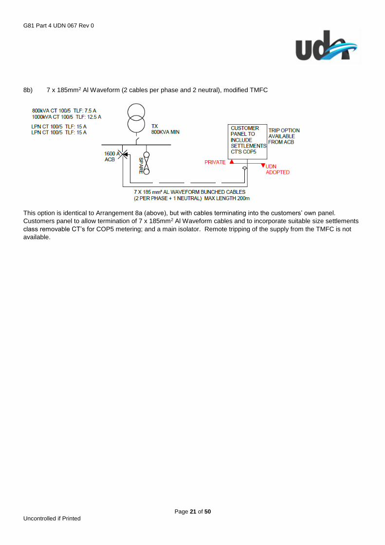
8b) 7 x 185mm2 Al Waveform (2 cables per phase and 2 neutral), modified TMFC
This option is identical to Arrangement 8a (above), but with cables terminating into the customers’ own panel.
Customers panel to allow termination of 7 x 185mm2 Al Waveform cables and to incorporate suitable size settlements
class removable CT’s for COP5 metering; and a main isolator. Remote tripping of the supply from the TMFC is not
available.
G81 Part 4 UDN 067 Rev 0
Page 22 of 50 Uncontrolled if Printed
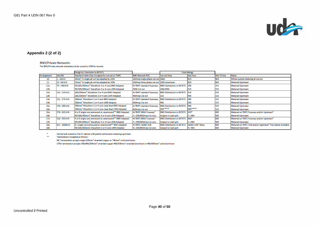
3.13.2 Arrangements for BNO and Private Networks
See Appendices 2 & 3 for summary and space requirements
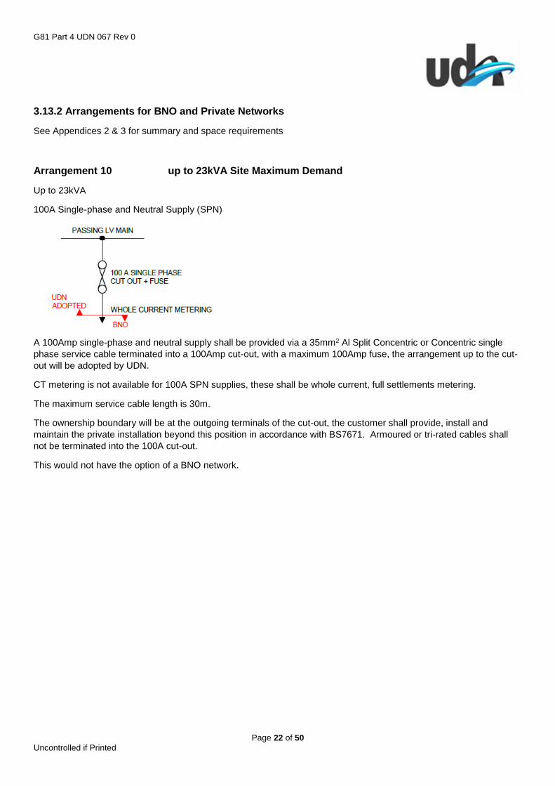
Arrangement 10 up to 23kVA Site Maximum Demand
Up to 23kVA
100A Single-phase and Neutral Supply (SPN)
A 100Amp single-phase and neutral supply shall be provided via a 35mm2 Al Split Concentric or Concentric single
phase service cable terminated into a 100Amp cut-out, with a maximum 100Amp fuse, the arrangement up to the cut-
out will be adopted by UDN.
CT metering is not available for 100A SPN supplies, these shall be whole current, full settlements metering.
The maximum service cable length is 30m.
The ownership boundary will be at the outgoing terminals of the cut-out, the customer shall provide, install and
maintain the private installation beyond this position in accordance with BS7671. Armoured or tri-rated cables shall
not be terminated into the 100A cut-out.
This would not have the option of a BNO network.
G81 Part 4 UDN 067 Rev 0
Page 23 of 50 Uncontrolled if Printed
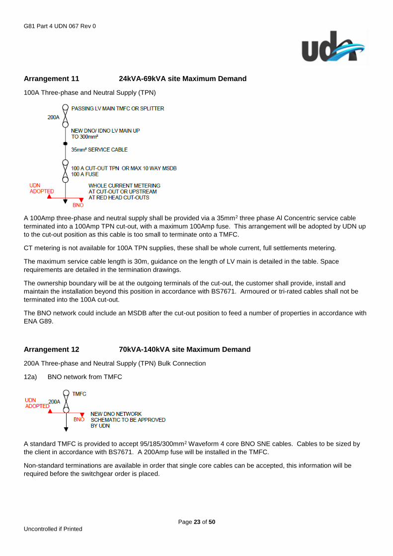
Arrangement 11 24kVA-69kVA site Maximum Demand
100A Three-phase and Neutral Supply (TPN)
A 100Amp three-phase and neutral supply shall be provided via a 35mm2 three phase Al Concentric service cable
terminated into a 100Amp TPN cut-out, with a maximum 100Amp fuse. This arrangement will be adopted by UDN up
to the cut-out position as this cable is too small to terminate onto a TMFC.
CT metering is not available for 100A TPN supplies, these shall be whole current, full settlements metering.
The maximum service cable length is 30m, guidance on the length of LV main is detailed in the table. Space
requirements are detailed in the termination drawings.
The ownership boundary will be at the outgoing terminals of the cut-out, the customer shall provide, install and
maintain the installation beyond this position in accordance with BS7671. Armoured or tri-rated cables shall not be
terminated into the 100A cut-out.
The BNO network could include an MSDB after the cut-out position to feed a number of properties in accordance with
ENA G89.
Arrangement 12 70kVA-140kVA site Maximum Demand
200A Three-phase and Neutral Supply (TPN) Bulk Connection
12a) BNO network from TMFC
A standard TMFC is provided to accept 95/185/300mm2 Waveform 4 core BNO SNE cables. Cables to be sized by
the client in accordance with BS7671. A 200Amp fuse will be installed in the TMFC.
Non-standard terminations are available in order that single core cables can be accepted, this information will be
required before the switchgear order is placed.
G81 Part 4 UDN 067 Rev 0
Page 24 of 50 Uncontrolled if Printed
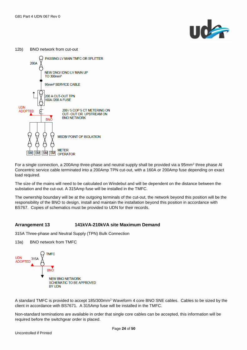
12b) BNO network from cut-out
For a single connection, a 200Amp three-phase and neutral supply shall be provided via a 95mm2 three phase Al
Concentric service cable terminated into a 200Amp TPN cut-out, with a 160A or 200Amp fuse depending on exact
load required.
The size of the mains will need to be calculated on Windebut and will be dependent on the distance between the
substation and the cut-out. A 315Amp fuse will be installed in the TMFC.
The ownership boundary will be at the outgoing terminals of the cut-out, the network beyond this position will be the
responsibility of the BNO to design, install and maintain the installation beyond this position in accordance with
BS767. Copies of schematics must be provided to UDN for their records.
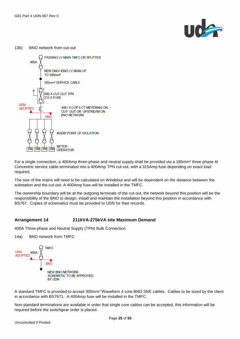
Arrangement 13 141kVA-210kVA site Maximum Demand
315A Three-phase and Neutral Supply (TPN) Bulk Connection
13a) BNO network from TMFC
A standard TMFC is provided to accept 185/300mm2 Waveform 4 core BNO SNE cables. Cables to be sized by the
client in accordance with BS7671. A 315Amp fuse will be installed in the TMFC.
Non-standard terminations are available in order that single core cables can be accepted, this information will be
required before the switchgear order is placed.
G81 Part 4 UDN 067 Rev 0
Page 25 of 50 Uncontrolled if Printed
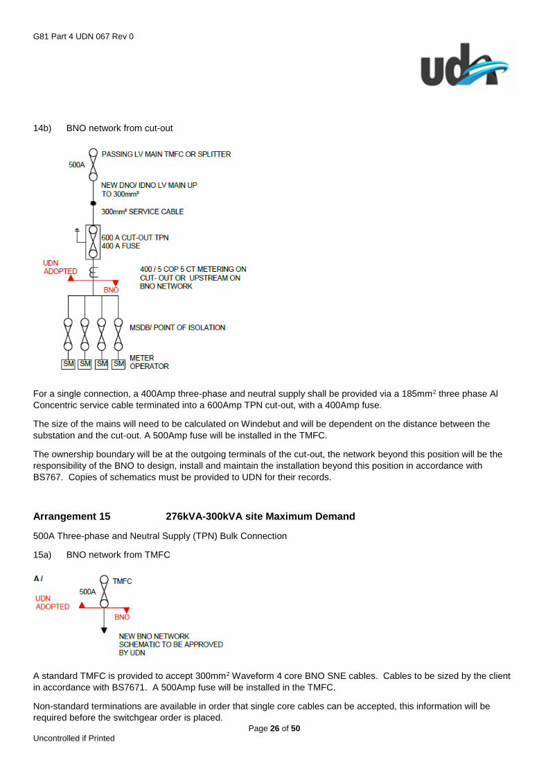
13b) BNO network from cut-out
For a single connection, a 400Amp three-phase and neutral supply shall be provided via a 185mm2 three phase Al
Concentric service cable terminated into a 400Amp TPN cut-out, with a 315Amp fuse depending on exact load
required.
The size of the mains will need to be calculated on Windebut and will be dependent on the distance between the
substation and the cut-out. A 400Amp fuse will be installed in the TMFC.
The ownership boundary will be at the outgoing terminals of the cut-out, the network beyond this position will be the
responsibility of the BNO to design, install and maintain the installation beyond this position in accordance with
BS767. Copies of schematics must be provided to UDN for their records.
Arrangement 14 211kVA-275kVA site Maximum Demand
400A Three-phase and Neutral Supply (TPN) Bulk Connection
14a) BNO network from TMFC
A standard TMFC is provided to accept 300mm2 Waveform 4 core BNO SNE cables. Cables to be sized by the client
in accordance with BS7671. A 400Amp fuse will be installed in the TMFC.
Non-standard terminations are available in order that single core cables can be accepted, this information will be
required before the switchgear order is placed.
G81 Part 4 UDN 067 Rev 0
Page 26 of 50 Uncontrolled if Printed
14b) BNO network from cut-out
For a single connection, a 400Amp three-phase and neutral supply shall be provided via a 185mm2 three phase Al
Concentric service cable terminated into a 600Amp TPN cut-out, with a 400Amp fuse.
The size of the mains will need to be calculated on Windebut and will be dependent on the distance between the
substation and the cut-out. A 500Amp fuse will be installed in the TMFC.
The ownership boundary will be at the outgoing terminals of the cut-out, the network beyond this position will be the
responsibility of the BNO to design, install and maintain the installation beyond this position in accordance with
BS767. Copies of schematics must be provided to UDN for their records.
Arrangement 15 276kVA-300kVA site Maximum Demand
500A Three-phase and Neutral Supply (TPN) Bulk Connection
15a) BNO network from TMFC
A standard TMFC is provided to accept 300mm2 Waveform 4 core BNO SNE cables. Cables to be sized by the client
in accordance with BS7671. A 500Amp fuse will be installed in the TMFC.
Non-standard terminations are available in order that single core cables can be accepted, this information will be
required before the switchgear order is placed.
G81 Part 4 UDN 067 Rev 0
Page 27 of 50 Uncontrolled if Printed
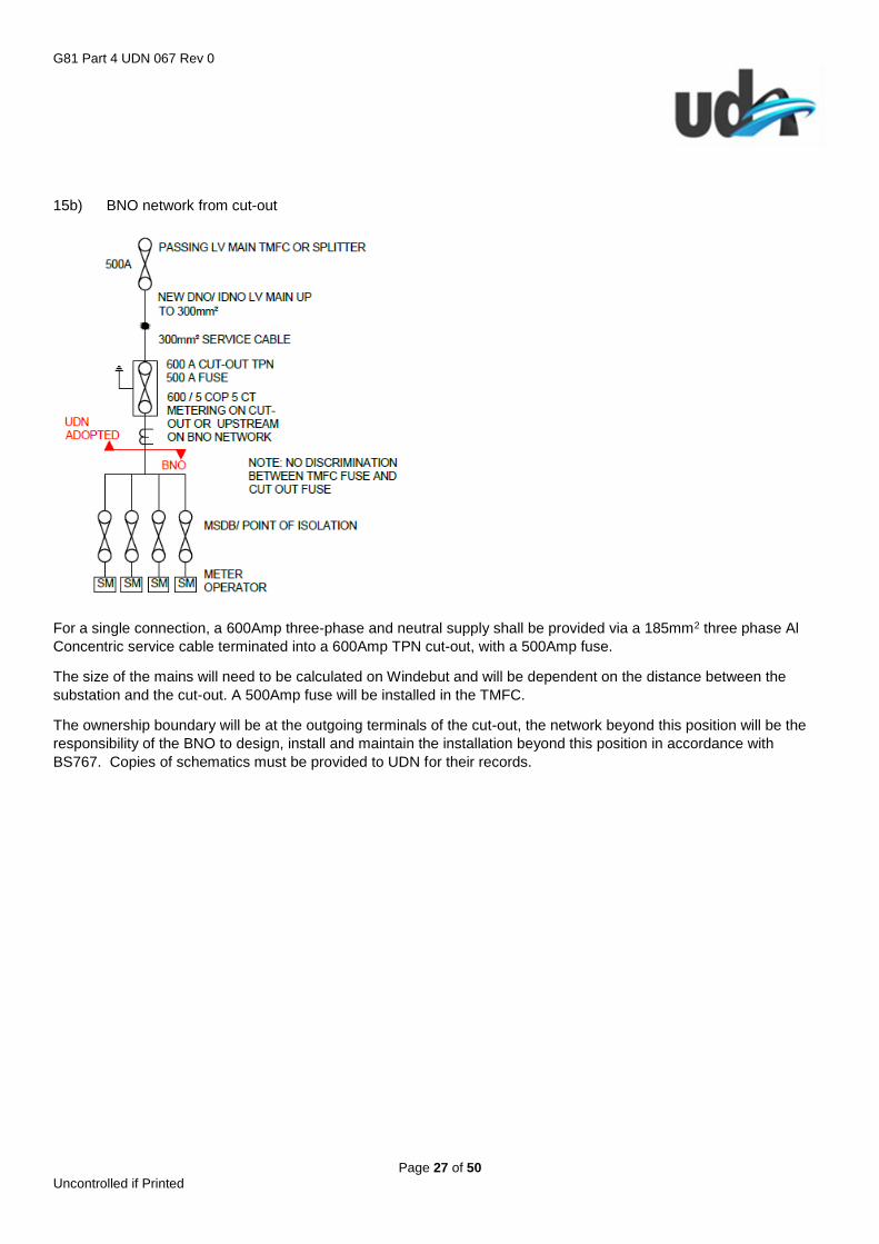
15b) BNO network from cut-out
For a single connection, a 600Amp three-phase and neutral supply shall be provided via a 185mm2 three phase Al
Concentric service cable terminated into a 600Amp TPN cut-out, with a 500Amp fuse.
The size of the mains will need to be calculated on Windebut and will be dependent on the distance between the
substation and the cut-out. A 500Amp fuse will be installed in the TMFC.
The ownership boundary will be at the outgoing terminals of the cut-out, the network beyond this position will be the
responsibility of the BNO to design, install and maintain the installation beyond this position in accordance with
BS767. Copies of schematics must be provided to UDN for their records.

G81 Part 4 UDN 067 Rev 0
Page 28 of 50 Uncontrolled if Printed
Arrangement 16 276kVA-415kVA site Maximum Demand
600A Three-phase and Neutral Supply (TPN) Bulk Connection
16a) BNO network from TMFC
Minimum transformer size 800kVA
A non-standard TMFC is provided with two ways adapted to provide a 600Amp supply. This will accept either 4 or 8
single core armoured or unarmoured cables, which will need to be sized by the client in accordance with BS7671.
Correct lugs and glands need to be provided as follows: -
ML7 terminations for single 630mm2 stranded copper or 740mm2 solid aluminium cables.
UT9/I terminations for 300/400/500mm2 stranded copper; 400/500mm2 stranded aluminium or 480/600mm2 solid
aluminium.
Metering class CT’s can be provided at the large fuse way at the TMFC to run multicore meter cable to a suitable
position within 15m cable length and/or on the upstream BNO network.
G81 Part 4 UDN 067 Rev 0
Page 29 of 50 Uncontrolled if Printed
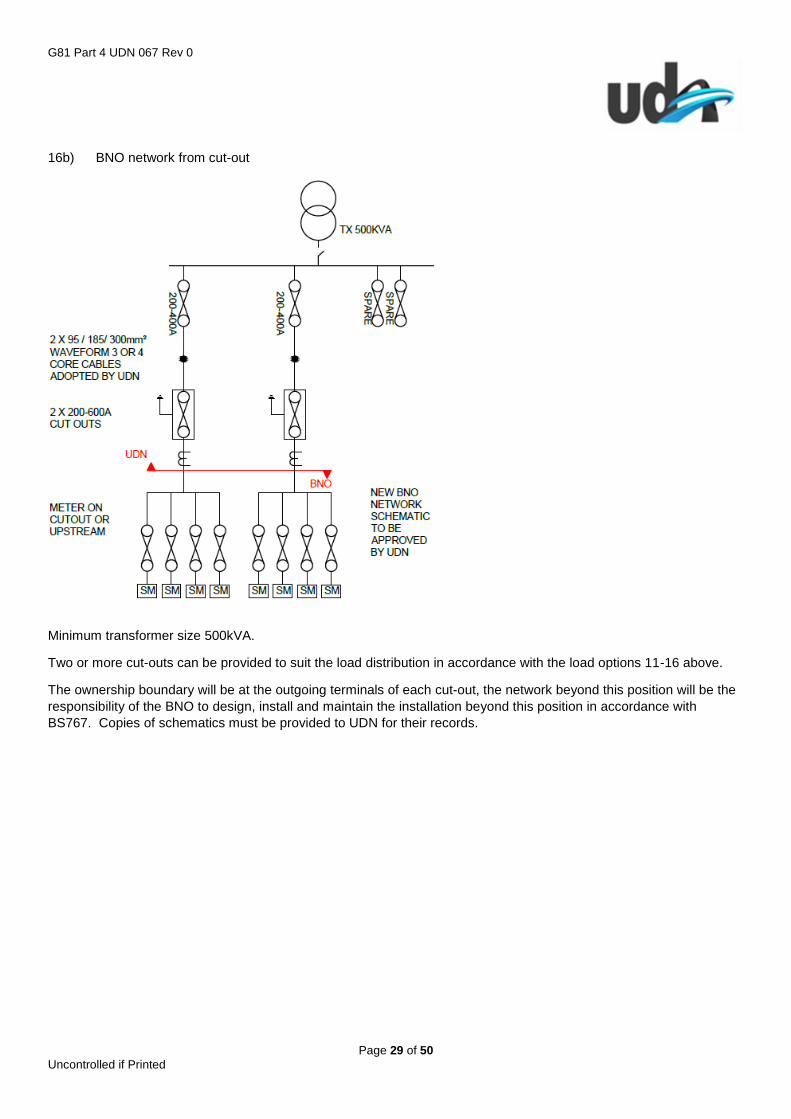
16b) BNO network from cut-out
Minimum transformer size 500kVA.
Two or more cut-outs can be provided to suit the load distribution in accordance with the load options 11-16 above.
The ownership boundary will be at the outgoing terminals of each cut-out, the network beyond this position will be the
responsibility of the BNO to design, install and maintain the installation beyond this position in accordance with
BS767. Copies of schematics must be provided to UDN for their records.
G81 Part 4 UDN 067 Rev 0
Page 30 of 50 Uncontrolled if Printed
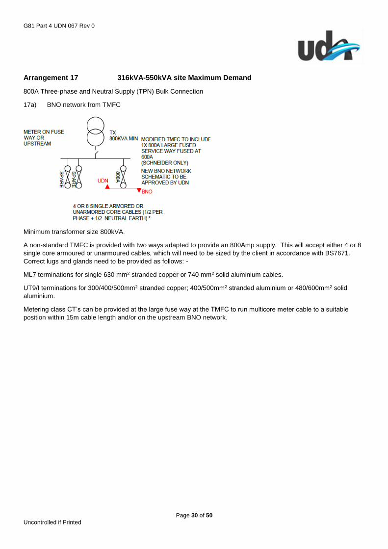
Arrangement 17 316kVA-550kVA site Maximum Demand
800A Three-phase and Neutral Supply (TPN) Bulk Connection
17a) BNO network from TMFC
Minimum transformer size 800kVA.
A non-standard TMFC is provided with two ways adapted to provide an 800Amp supply. This will accept either 4 or 8
single core armoured or unarmoured cables, which will need to be sized by the client in accordance with BS7671.
Correct lugs and glands need to be provided as follows: -
ML7 terminations for single 630 mm2 stranded copper or 740 mm2 solid aluminium cables.
UT9/I terminations for 300/400/500mm2 stranded copper; 400/500mm2 stranded aluminium or 480/600mm2 solid
aluminium.
Metering class CT’s can be provided at the large fuse way at the TMFC to run multicore meter cable to a suitable
position within 15m cable length and/or on the upstream BNO network.

G81 Part 4 UDN 067 Rev 0
Page 31 of 50 Uncontrolled if Printed
17b) BNO network from cut-out
Minimum transformer size 500kVA.
Two or more cut-outs can be provided to suit the load distribution. These will be sized in accordance with the load
options 11-16 above.
The ownership boundary will be at the outgoing terminals of each cut-out, the network beyond this position will be the
responsibility of the BNO to design, install and maintain the installation beyond this position in accordance with
BS767. Copies of schematics must be provided to UDN for their records.
G81 Part 4 UDN 067 Rev 0
Page 32 of 50 Uncontrolled if Printed
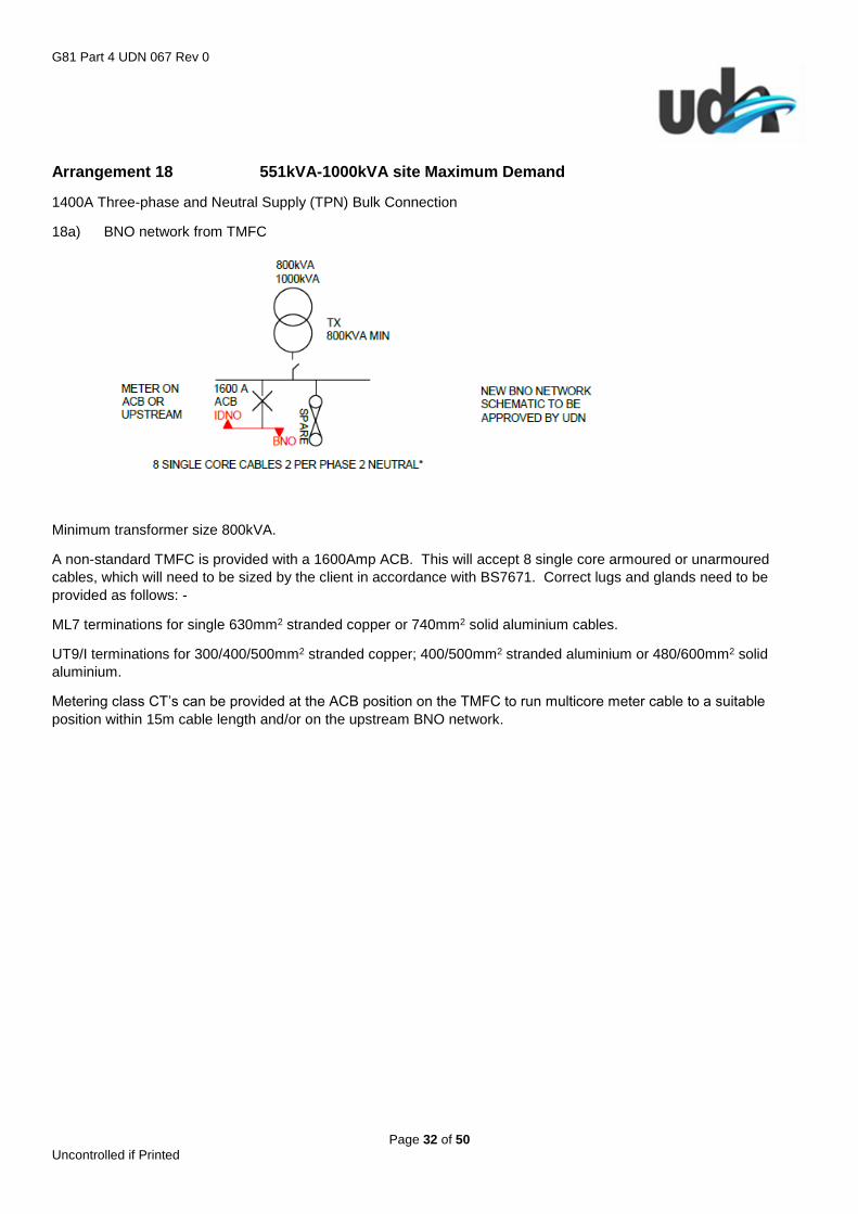
Arrangement 18 551kVA-1000kVA site Maximum Demand
1400A Three-phase and Neutral Supply (TPN) Bulk Connection
18a) BNO network from TMFC
Minimum transformer size 800kVA.
A non-standard TMFC is provided with a 1600Amp ACB. This will accept 8 single core armoured or unarmoured
cables, which will need to be sized by the client in accordance with BS7671. Correct lugs and glands need to be
provided as follows: -
ML7 terminations for single 630mm2 stranded copper or 740mm2 solid aluminium cables.
UT9/I terminations for 300/400/500mm2 stranded copper; 400/500mm2 stranded aluminium or 480/600mm2 solid
aluminium.
Metering class CT’s can be provided at the ACB position on the TMFC to run multicore meter cable to a suitable
position within 15m cable length and/or on the upstream BNO network.

G81 Part 4 UDN 067 Rev 0
Page 33 of 50 Uncontrolled if Printed
a) BNO network from cut-out
Minimum transformer size 800kVA.
Two or more cut-outs can be provided to suit the load distribution. These will be sized in accordance with the load
options 11-16 above.
The ownership boundary will be at the outgoing terminals of each cut-out, the network beyond this position will be the
responsibility of the BNO to design, install and maintain the installation beyond this position in accordance with
BS767. Copies of schematics must be provided to UDN for their records.
Protection Settings for the 1600A ACB are as follows: -
Up to 800kVA Up to 1000kVA
In = 1600A In = 1600A
Ir = 1280A (0.8 x In) Ir = 1440A (0.9 x In)
tr = 1s @ 6 x Ir tr = 1s @ 6 x Ir
Isd = 2560A (2 x Ir) Isd = 2880A (2 x Ir)
tsd = 0s, I2t off tsd = 0s, I2t off
Ii = 4800A (3 x In) Ii = 4800A (3 x In)

G81 Part 4 UDN 067 Rev 0
Page 34 of 50 Uncontrolled if Printed
3.14 HV Customer Connections
For single customer connections above 1,000kVA then a HV metered option can be provided. Alternatively, where the
customer load needs to be metered at HV then this can be offered with a minimum Chargeable Capacity of 500kVA.
The standard arrangement for connection of a single private customer transformer with a maximum nameplate rating
of 3,800kVA will be a private cable connection from a single Ring Main Unit with relay protection and a close coupled
3 limb metering unit.
Connection of multiple transformers up to a maximum nameplate rating of 3,800kVA will require a customer owned
11kV multi-panel board to be installed on the private network, with appropriate protection to feed each transformer. In
this arrangement, the multi-panel board will be supplied by a private cable connection from a single Ring Main Unit
with relay protection and a close coupled 3 limb metering unit.
With both these arrangements the private network boundary will be at the outgoing connections of the HV metering
unit; the Ring Main Unit will be a looped connection unless a written agreement is received from the client.
3.15 Substation General
UDN will require as a preference freehold ownership of any substation or switch room, a 99-year lease will be
acceptable as an alternative/in exceptional circumstances. Legal agreements must be in place prior to energisation.
Substation type will be based on a risk Assessment of the location (see Appendix 1). The minimum requirement is a
GRP enclosure.
24-hour vehicle and pedestrian access is required to the substation doors.
If access is required through security gates then an over-ride key, located in a secure box on an adjacent wall will be
required. Access via a security guard, electrically or coded access will not be acceptable.
Where the Host DNO provides the HV POC the Substation services (Small Power & Lighting) will follow the Host DNO
requirements in regards to the number of sockets, lights, RTU supplies. Where the substation has an LV Pillar, supply
will be taken from the 32A Aux way in the LV Pillar. In the case of a HV Customer Substation, the supply will be
provided from the customers LV system. The installation will comprise a metal clad Distribution Board and either high
impact PVC or galvanised steel conduit and trunking, with appropriate fittings.
For unit substations where UDN provide the HV POC, an additional light (only) will be provided, connected to the
lighting aux supply in the LV Pillar. For HV Customer substations where the HV POC is from UDN, the LV supply will
be provided from the customers LV system. The installation will comprise a metal clad Distribution Board and either
high impact PVC or galvanised steel, conduit and trunking with appropriate fittings, and will include a light and socket
as a minimum. A thermostatically controlled heater may also be required if the HV customer switch room is
standalone.
All small power and lighting installation will conform to BS 7671.
Where ducted cable entries into the substation are required these must be sealed. The ducts must also be sealed
between the outside of the ducts and the building structure. In both cases the seal selected must provide a liquid and
gas tight seal; this may take the form of mastic, expanding foam or a mechanical seal.
3.15.1 Substation Ventilation General
The ventilation must be sufficient to ensure the maximum room temperature does not exceed 40 C when the
transformers/plant are operating at their nameplate rating.
Wherever possible natural air flow to the outside of the building must be used.

G81 Part 4 UDN 067 Rev 0
Page 35 of 50 Uncontrolled if Printed
Vents must be positioned to provide cross ventilation across the transformer/plant with a minimum of 1m2 of inlet area
and 1m2 of outlet area per 1000kVA, for Free Standing Substations. For integral substations, the minimum ventilation
area must be increased to a minimum of 1.5m2 of inlet area and 1.5m2 of outlet area per 1000kVA.
Substantial vertical separation is required between the inlet and outlet openings to allow natural convection, they
should be clear of pedestrian areas and must be located to prevent gases such as vehicle exhausts, and pollutants
such as smoke, entering the substation.
The louvres must be designed horizontally to prevent the ingress of driving rain, they must also be vermin proof,
weather proof and designed to prevent them being dislodged or foreign objects being inserted through them.
Forced ventilation is the most unreliable method of ventilation that also requires frequent maintenance, for this reason
UDN will only accept this solution in exceptional circumstances, and may reduce the AV accordingly.
3.15.2 Freestanding Distribution Substation (GRP/Brick)
Subject to the risk assessment the minimum requirement would be a GRP housing. Brick built substations are also
acceptable and shall be incorporated into the design:
It is essential that the external area around the louvres is kept clear, a minimum space of 500mm is therefore required
around all substations. Designers should make developers aware that the planting around substations should be
restricted or kept away from the boundary of the substation so as not to reduce ventilation as the planting matures.
Substation doors (can be GRP or Steel) and must be compliant with UDN G81 Materials Specification.
Wooden doors will not be acceptable.
Brick buildings shall have a pitched GRP roof that is removable.
HV equipment will require a minimum of 750mm clearance in front for operational purposes.
Ventilation will be via low level ‘inlet’ louvres and with high level ‘outlet’ louvres behind positioned to provide cross flow
ventilation over the transformer, plant or equipment.
Louvres must not be located in areas where heat or smoke dissipation could compromise adjoining escape routes.
Where the building is GRP the louvres shall be built into the GRP housing. Where a brick building is provided, they are
to be of either air bricks or steel construction within a steel frame and secured internally be suitable anchor fixings into
the brickwork with no external fixings.
See typical layout drawing references: - UDN 430/440 (GRP); UDN 450/460 (Brick).
3.15.3 Integral/Basement Substations
When determining the location of an integral substation, careful consideration needs to be given to the following:
Pedestrian access for operational purposes
Vehicle access for the installation, maintenance, replacement of the plant & equipment
Ventilation to ensure temperatures do not become excessive
Fire spread both to and from the substation
Noise & Vibration; Attenuation mats must be installed in all integral substations.
UDN will require unrestricted 24-hour pedestrian and vehicle access from the public highway. Where an access
gate/door is provided at the highway boundary this must have dual locking, UDN will provide a suitable padlock.
Electrically or coded access will not be acceptable.
G81 Part 4 UDN 067 Rev 0
Page 36 of 50 Uncontrolled if Printed
Plant and equipment deliveries are by HGV’s which will normally have a Hiab for off-loading. Maintenance vehicles
are generally large vans, which may have a trailer. UDN’s preference is for vehicle access to within a few metres of
the substation. However, where this cannot be provided with integral substations, the client/architect/designer will
have to provide a suitable drop-off point as close as possible, and provide a suitable route to the substation taking into
account the weight/size of the plant/equipment being installed, in accordance with the CDM regulations.
A minimum operational and maintenance clearance will be required around the equipment of 750mm. As a guide a
typical unit substation will require a minimum room size of 4m x 4m x 2.5m high.
For integral substations ventilation is best achieved by siting the substation on the corner of the building and venting
on both external faces to generate good cross flow ventilation.
The minimum ventilation area must be increased to a minimum of 1.5m2 of inlet area and 1.5m2 of outlet area per
1000kVA.
Natural cross flow ventilation from/to outside across the transformer is the most robust means of ventilation, and is
UDN’s preferred method.
Where the substation position does not have outside walls natural ventilation can be achieved using ducted air
inlets/outlets that have vertical separation. Such ducted ventilation routes need to be as short and direct as possible to
outside and be dedicated to the substation.
Inlets/outlets should be away from or above pedestrian areas, positioned so as not to draw-in exhaust fumes, or other
pollutants and will be fitted with suitable grills to prevent access or vermin.
Forced ventilation is the most unreliable method of ventilation that also requires frequent maintenance, for this reason
UDN will only accept this solution in exceptional circumstances, and may reduce the AV accordingly.
For a substation enclosure that forms part of the building fabric of the development then the following additional items
shall be incorporated into the design: -
The building fabric must provide 4-hour fire rating
Basement substations will require blast proof doors, with specific opening formed from reinforced concrete or
solid engineering brick.
Consideration may need to be given to the spread of fire both from/to the substation. Integral substations will be
designed to provide a 4hr fire rating and comply with building and fire regulations. Fire shutters will not be accepted
due to ventilation and maintenance issues.

G81 Part 4 UDN 067 Rev 0
Page 37 of 50 Uncontrolled if Printed
Appendix 1 (1 of 2)
UDN Distribution Substation Risk Assessment
The following steps are required to undertake a risk assessment, the report to be included in the design approval
process.
1. Look up project on google street view and look around the local area looking for Schools, Play Areas, Public Open Spaces and or other similar areas, local Graffiti acts and public damage etc.
2. Look up the project area on https://www.police.uk/ to review the reported crime in the past 12months within 1mile
of the project.
3. The total number of crimes should less than 240 for low risk, up to 500 for medium risk and 501 and above high risk for the past 12months.
4. The types and number of crimes committed in the local area that fall into the following categories should be less than 100 per category to achieve low risk
a. Anti-social behaviour b. Burglary c. Criminal damage and arson d. Drugs e. Other crime f. Other theft g. Possession of weapons h. Violence and sexual offences
5. The types and percentage of crimes committed in the local area that fall into the following categories should total less than 30% for low risk, 31%-70% for medium risk and 70% and above is high risk
a. Anti-social behaviour b. Burglary c. Criminal damage and arson d. Other theft
6. The results for items 3,4 & 5 should all be within the same category if you have differing category results please check with UDN.
7. The results need to be issued to UDN with the design approval in the following format: -
With reference to above project, after looking at the Anti-Social Behaviour, Burglary, Criminal Damage and Arson, and Other Theft per annum within 1 mile of the site together they equal % for the period between ____ to ____. I would suggest that this project is a risk and therefore a built Substation with doors and
louvres would be required.
G81 Part 4 UDN 067 Rev 0
Page 38 of 50 Uncontrolled if Printed
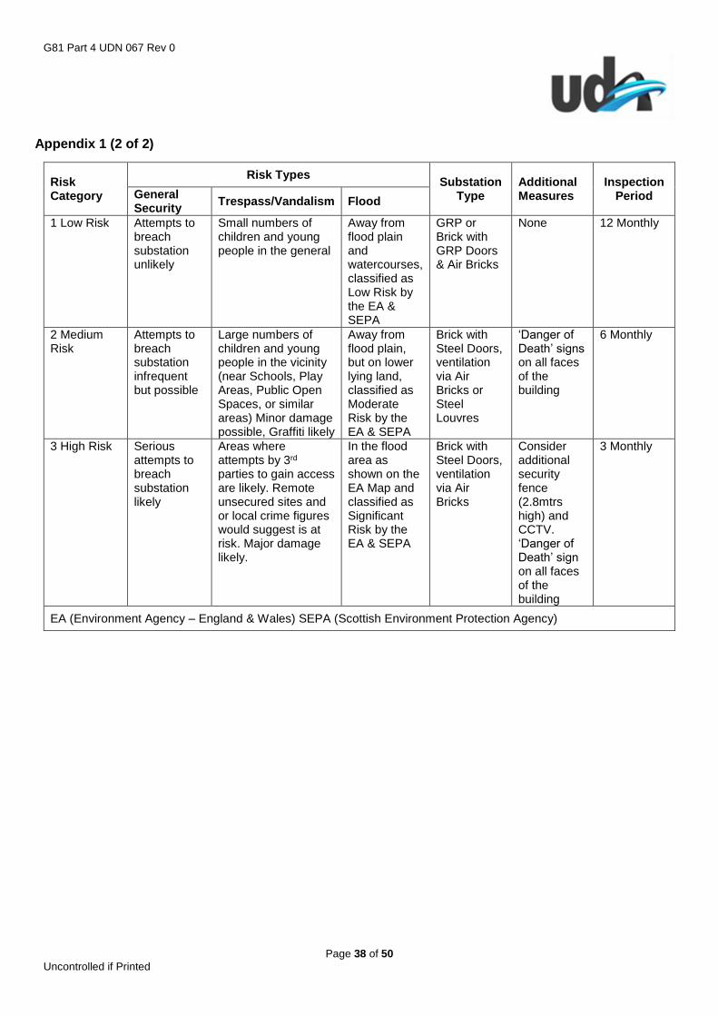
Appendix 1 (2 of 2)
Risk Category
Risk Types Substation
Type Additional Measures
Inspection Period General
Security Trespass/Vandalism Flood
1 Low Risk Attempts to breach substation unlikely
Small numbers of children and young people in the general
Away from flood plain and watercourses, classified as Low Risk by the EA & SEPA
GRP or Brick with GRP Doors & Air Bricks
None 12 Monthly
2 Medium Risk
Attempts to breach substation infrequent but possible
Large numbers of children and young people in the vicinity (near Schools, Play Areas, Public Open Spaces, or similar areas) Minor damage possible, Graffiti likely
Away from flood plain, but on lower lying land, classified as Moderate Risk by the EA & SEPA
Brick with Steel Doors, ventilation via Air Bricks or Steel Louvres
‘Danger of Death’ signs on all faces of the building
6 Monthly
3 High Risk Serious attempts to breach substation likely
Areas where attempts by 3rd parties to gain access are likely. Remote unsecured sites and or local crime figures would suggest is at risk. Major damage likely.
In the flood area as shown on the EA Map and classified as Significant Risk by the EA & SEPA
Brick with Steel Doors, ventilation via Air Bricks
Consider additional security fence (2.8mtrs high) and CCTV. ‘Danger of Death’ sign on all faces of the building
3 Monthly
EA (Environment Agency – England & Wales) SEPA (Scottish Environment Protection Agency)
G81 Part 4 UDN 067 Rev 0
Page 39 of 50 Uncontrolled if Printed
Appendix 2 (1 of 2)
G81 Part 4 UDN 067 Rev 0
Page 40 of 50 Uncontrolled if Printed
Appendix 2 (2 of 2)

G81 Part 4 UDN 067 Rev 0
Page 41 of 50 Uncontrolled if Printed

G81 Part 4 UDN 067 Rev 0
Page 42 of 50 Uncontrolled if Printed

G81 Part 4 UDN 067 Rev 0
Page 43 of 50 Uncontrolled if Printed
G81 Part 4 UDN 067 Rev 0
Page 44 of 50 Uncontrolled if Printed

G81 Part 4 UDN 067 Rev 0
Page 45 of 50 Uncontrolled if Printed
G81 Part 4 UDN 067 Rev 0
Page 46 of 50 Uncontrolled if Printed
G81 Part 4 UDN 067 Rev 0
Page 47 of 50 Uncontrolled if Printed
Service termination cubicles. Drawings to be completed.
G81 Part 4 UDN 067 Rev 0
Page 48 of 50 Uncontrolled if Printed

G81 Part 4 UDN 067 Rev 0
Page 49 of 50 Uncontrolled if Printed

G81 Part 4 UDN 067 Rev 0
Page 50 of 50 Uncontrolled if Printed


