UNCLASSIFIED
AD NUMBER
LIMITATION CHANGESTO:
FROM:
AUTHORITY
THIS PAGE IS UNCLASSIFIED
AD482263
Approved for public release; distribution isunlimited.
Distribution authorized to U.S. Gov't. agenciesand their contractors;Administrative/Operational Use; 1962. Otherrequests shall be referred to U.S. NavalPostgraduate School, Monterey, CA 93943.
USNPS ltr, 18 Oct 1971

n, mwai poTgTadUMe school

DUDLEY KNOX LIBRARYNAVAL POSTGRADUATE SCHOOLMONTEREY, CALIFORNIA 93943
DESIGN AND CONSTRUCTION
OF A STEADY STATE
PLASMA STUDY FACILITY
*****
John B. Streit
and
Walter E, Olsen
DESIGN AND CONSTRUCTION
OF A STEADY STATE
PLASMA STUDY FACILITY
by
John Bo St re it
Lieutenant.,, United States Navy
and
Walter E. Olsen
Lieutenant, United States Navy
Submitted in partial fulfillment of
the requirements for the degree of
MASTER OF SCIENCEIN
PHYSICS
United States Naval Postgraduate SchoolMonterey, California
1962
LIBRARY
U.S. NAVAL POSTGRADUATE SCHOOL
MONTEREY, CALIFORNIA
DESIGN AND CONSTRUCTION
OF A STEADY STATE
PLASMA STUDY FACILITY
by
John B. Streit
and
Walter E. Olsen
This work is accepted as fulfilling
the thesis requirements for the degree of
MASTER OF SCIENCE
IN
PHYSICS
from the
United States Naval Postgraduate School
ABSTRACT
The plasma study facility was conceived as a steady state, highly
ionized plasma system for use by the plasma physics group of the Physics
Department of the U.S. Naval Postgraduate School, Monterey, California.
The primary objectives will be the study of electro-magnetic, Alfven
and ion waves in a plasma, electron and ion beam interactions, and the
diffusion of the plasma in magnetic fields. Various diagnostic techni=
ques are envisioned, including Langmuir and magnetic probes, microwave,
and spectroscopic measurements.
The plasma column is nine feet long and about two cm in diameter,
depending upon the magnitude of the longitudinal magnetic field. It
is contained in a pyrex glass cylinder four inches in diameter with
access ports every 14 inches for diagnostic equipment. The system is
designed to operate at a source gas pressure of approximately one to
five microns utilizing differential pumping of neutral particles. The
first mode of operation will employ a hollow cathode reflex arc dis-
charge. It is expected that the discharge will carry up to 150 amps
at approximately 100 volts, The longitudinal magnetic field in the
plasma column will be variable up to 10,000 gauss, and homogeneous to
within 2,5% along the axis of the plasma column.
Design and details of construction (except for the field coils
and field power supplies) are presented with operating instructions
and expenditure data,
The writers wish to express their appreciation for the technical
supervision given by Professor N,L. Oleson and Professor A,W. Cooper,
and for the assistance of Mr, Michael O'Dea and Mr. Robert Smith,
ii
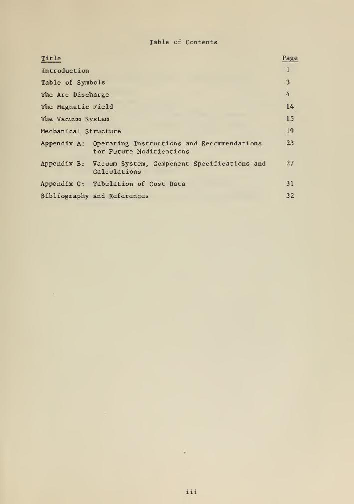
Table of Contents
Title Page
Introduction 1
Table of Symbols 3
The Arc Discharge 4
The Magnetic Field 14
The Vacuum System 15
Mechanical Structure 19
Appendix A: Operating Instructions and Recommendations 23
for Future Modifications
Appendix B: Vacuum System, Component Specifications and 27
Calculations
Appendix C: Tabulation of Cost Data 31
Bibliography and References 32
in
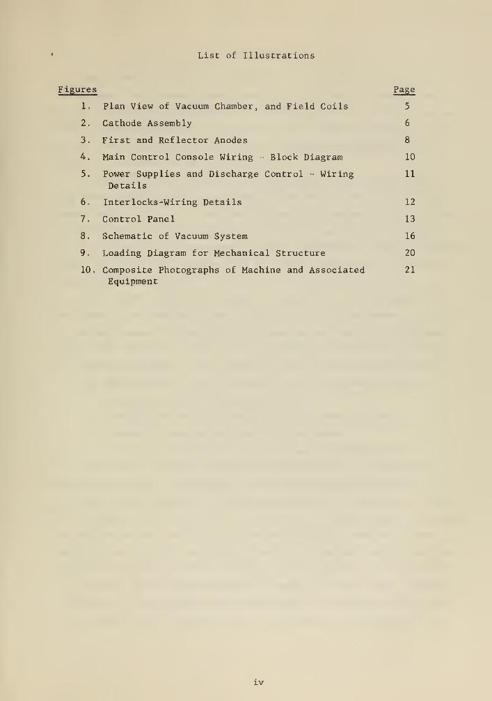
List of Illustrations
Figures Page
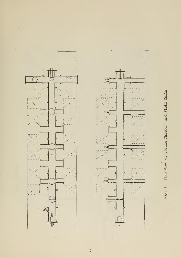
1. Plan View of Vacuum Chamber, and Field Coils 5
2. Cathode Assembly 6
3. First and Reflector Anodes 8
4. Main Control Console Wiring = Block Diagram 10
5. Power Supplies and Discharge Control - Wiring 11
Details
6. Inter locks-Wiring Details 12
7. Control Panel 13
8. Schematic of Vacuum System 16
9. Loading Diagram for Mechanical Structure 20
10 o Composite Photographs of Machine and Associated 21
Equipment
IV
Introduction
The plasma study facility will bring to the Physics Department of
the US Naval Postgraduate School, Monterey, California a research tool
wherein extensive investigations of the characteristics of highly-ionized,
steady state plasmas may be conducted . Other plasma systems were studied
and their most profitable features were combined and employed in this
facility, Embodied in the design are;
A magnetic field variable up to 10,000 gauss with no more than a
2.5% axial variation over approximately five feet of the nine foot long
plasma column. The field distribution includes a magnetic mirror at one
end with a minimum mirror ratio of 1.33 for maximum field conditions,
A differential vacuum pumping scheme resulting in a neutral pressure
of 10 mm Hg at the cathode end of the plasma column and a 10 mm Hg
at the reflecting anode
,
Five access stations for diagnostic equipment, evenly spaced over
each side of the constant magnetic field portion of the column.
A high degree of flexibility in changing the length of the plasma
column, the location of vacuum system components, the position of mag
net coils with respect to the chamber, and the type of cathode source.
The above features invite research into the following fields:
Diffusion across a magnetic field.
Propagation of electromagnetic and plasma-ion waves.
Generation and propagation of Alfven waves.
Interaction of ion and electron beams with the plasma.
Diagnostic techniques investigating the above will involve micro
wave, spectroscopic, and Langmuir and magnetic probe measurements.
This report presents the design and details of construction of the
arc discharge electrical circuits, components, and power supply including
the cathode source; the vacuum system including all associated power
supplies, cooling water and high pressure air plumbing; each of the fore-
going with necessary controls, metering, and interlocks; and the mechani-
cal structure of the vacuum chamber and support of the system. Although
formulation of the magnetic field requirements is discussed, the design
of the magnet coils to produce such a field was not undertaken by the
authors. A thorough investigation of coil design including power supplies
and water cooling requirements, was made by Prof. AW. Cooper of the US
Naval Postgraduate School and is available under separate cover.
The cost of the plasma facility is exceedingly low compared to
other operating systems of comparable size and objective „ The total
cost to place the machine into operation will be approximately $85,749
exclusive of measuring equipment. This includes $64,700 for the magnetic
field coils, their associated power supplies and water cooling service.
Funds for the preceeding figures are appropriated by the Office of Naval
Research. The foregoing does not include $3,366 utilized to bring elec-
trical, water and air services to the laboratory. Installation of these
services is to be accomplished by the Public Works Department of the US
Naval Postgraduate School and is funded by Maintenance and Operations
appropriations. Cost tabulations are presented in the Appendix.
At the time of the completion of the writing of this report, the
system was not operating with a discharge because of the lack of electrical
power services. Hence all performance parameters alluded to, such as volt=
age, current, or gas flow rates, are only those anticipated. All the con-
trol and interlock equipment, electrodes, and vacuum chamber and system
hardware have been assembled and installed. The system is presently in
the status of being leak tested. Specifications for the magnet field
coils and associated equipment have been sent out for bids.
As this report serves as a summary of laboratory employment and re-
search and will culminate the association of the graduate student authors
with this project, an appendix is included to provide operating instructions
for other students newly acquainted with the system and recommendations for
possible future modifications to improve system efficiency.
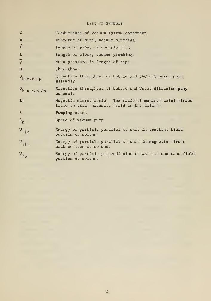
List of Symbols
b-cvc dp
b-veeco dp
S
SI
w
wm
Wi
Conductance of vacuum system component.
Diameter of pipe, vacuum plumbing.
Length of pipe, vacuum plumbing,
Length of elbow, vacuum plumbing.
Mean pressure in length of pipe.
Throughput
Effective throughput of baffle and CVC diffusion pumpassembly.
Effective throughput of baffle and Veeco diffusion pumpassembly.
Magnetic mirror ratio. The ratio of maximum axial mirrorfield to axial magnetic field in the column.
Pumping speed.
Speed of vacuum pump.
Energy of particle parallel to axis in constant fieldportion of column.
Energy of particle parallel to axis in magnetic mirrorpeak portion of column.
Energy of particle perpendicular to axis in constant fieldportion of column.

The Arc Discharge
The electrode configuration is as shown in Fig, 1, with a grounded
cathode and a positive potential on the first anode. The second anode
floats at about ground potential as does the brass cylinder containing
the cathode. Operation of the arc is then in the reflex mode. An axial
magnetic field up to 10,000 gauss will be employed in the plasma column
with a magnetic mirror having a mirror ratio equal to 1,33 minimum.
Differential pumping is established by the location of the diffusion
pumps and the magnetic mirror,
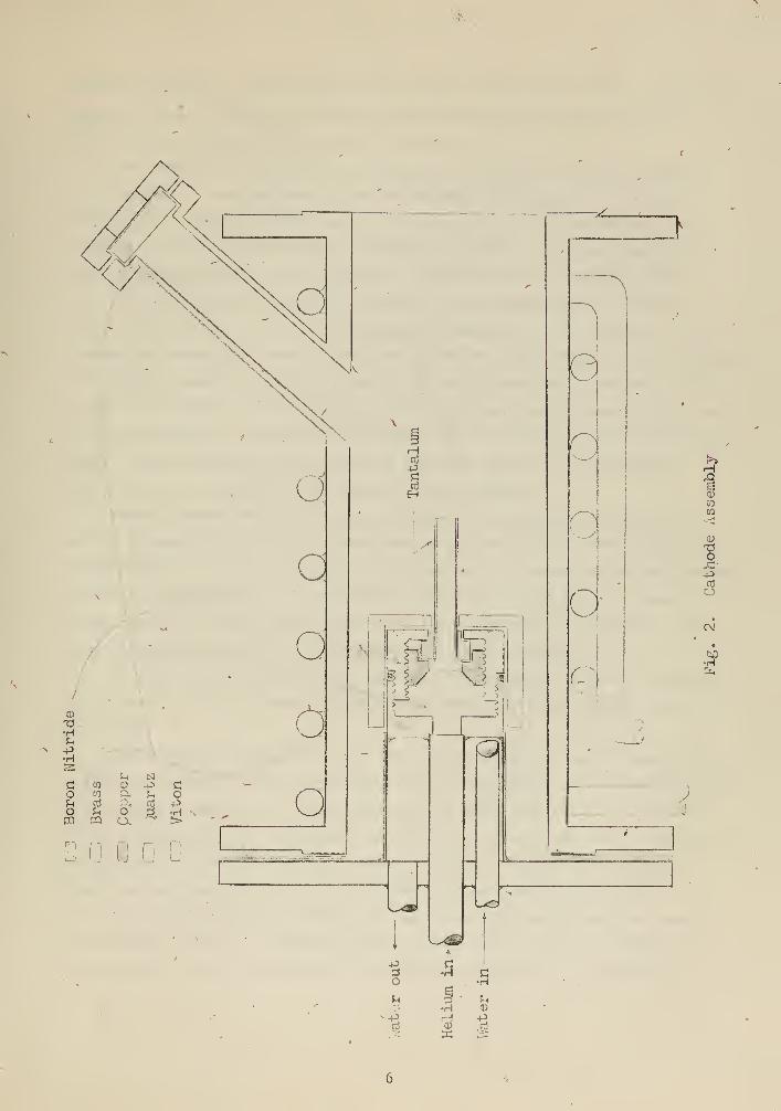
A diagram of the tantalum, hollow, cylindrical cathode is shown in
2Fig. 2, The design is very similiar to that used by Luce, Helium input
at less than 219 cc/min at 30 psia input pressure is considered sufficient
to provide the ion current desired. The helium gas must pass through six
cm of the tube before entering the vacuum chamber. This, and the fact that2
a hot spot about one cm long in the tube is expected to occur will en-
hance the probability of ionization. Generated heat is conducted away by
immersing the cathode base in a water jacket and swirling cooling water
around it at a flow rate of one gpm, The water temperature in the output
cooling line is interlocked into the arc power supply to provide a cut-out
for excessive heating. In the cathode base, provision is made to mount
tantalum tubing of various diameters. The tubing presently installed is
one-half inch in outside diameter and ,02 inches in wall thickness. All
threads are slotted to decrease pump down time, The four inch diameter
brass cylinder containing the cathode source is electrically insulated from
the cathode by a viton gasket and fiber bolts,
The highly ionized gas leaves the cathode at a pressure of a few mi-
crons. The annular first anode at a potential near 100 volts sustains
the discharge. The concentric hole in the copper anode, being 2,5 cm in
diameter, limits the diameter of the plasma column passing through it.
Water cooling is provided by copper tubing concentric around the anode.
Flow rate is about 0.2 gpm. Insulation of the anode in the water cooling
lines is provided by neoprene rubber hose.
The second anode at the extreme end of the column is a copper disc
three inches in diameter, which floats electrically, and acts as an
_J1Il=a
COH•r!
OO-o
•H
ShCD
.£}
IO
i
o>
o
•H>G
5J
•H
fl>
-xi
•HU-P•HS
^ Nc n Q) +3 cO w Cli tl oIm cfl crt po Ih o d •Hm ra o. >
D D
Q
G
O
o
«5
y
~^_
*V 'vi1?
5
3O
3)
s
t
a
3 ' £h
•H 0)
H -P
o
r.
IZ]
H3
a)
-aojd--pnSo
cv
#&H
electron reflector „ This electrode is water cooled with a water supply of
about 0.1 gpm. The use of neoprene rubber hose again provides insula-
tion. For a sketch of both anodes, see Fig. 3„
The benefits of differential pumping are evident in the P-4 machine3 4
at Livermore and the Mode II arc of Neidigh and Weaver „ The loca-
tion of the diffusion pumps and the booster pump of the system under dis-
cussion is such as to establish a pressure gradient along the discharge.
The recombination rate will be greater toward the anode reflector and
the neutrals will pass through the mirror to be pumped out by the com-
bined action of the two diffusion pumps at that end of the column „ Fol-
lowing the vernacular used in describing the P 4, this region may be termed
the "burial chamber", Neutral density in the column should be about 10
mm Hg at this point- The placement of the booster pump closer to this end
of the column will also aid by increasing the efficiency of these diffusion
pumps. An advantage of the system is that the position of the magnet
mirror coils is flexible with respect to the chamber.
Washer shaped baffles between each pair of pump-down ports are in
serted perpendicular to the column axis to assist in differential pumping.
The diameter of the concentric hole in each baffle through which the plasma
passes is presently 0.5 cm smaller than the hole in the anode. Boron ni-
tride, having a small vapor pressure, a low coefficient of expansion, and
good insulating properties, was chosen as the baffle material.
As reported in the discharge density investigation of the P-4 machine,
the plasma itself can also be expected to pump neutral particles very ef-
fectively.
For starting, breakdown of the gas may be brought about by supplying
energy to electrons via rf oscillations in the presence of a magnetic field
A frequency of 100 kc to a few megacycles at about 30 rms in a field of
a few hundred gauss is considered sufficient to ionize the gas. A spark-
gap generator found in the Airco welder starter, model HF-15 1, superim-
poses the necessary rf on a dc potential of approximately 100 volts. A
coil to provide 200 gauss will be placed around the source area to supply
the necessary field. A helium inflow of about one atm/cc sec would also
be necessary. After breakdown, the rf may be removed or, alternately,
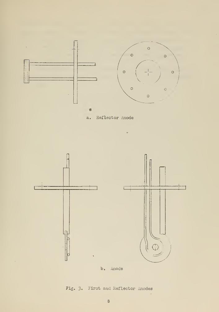
a. Reflector Anode
o
o
b . Anode
Fig. 3. First and Reflector Anodes
decreased in order to serve as a "keep alive" . This latter case would
enable a reduction in the dc anode-cathode potential but might introduce
oscillations into the plasma. In order to isolate the energy of the rf
oscillations from the cathode base and limit it to the area between the
tip of the cathode and first anode, the cathode base is capped by a
boron nitride insulating shield.
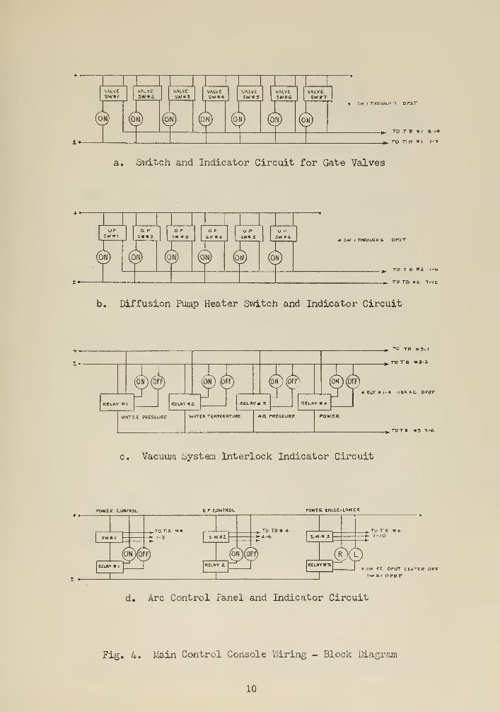
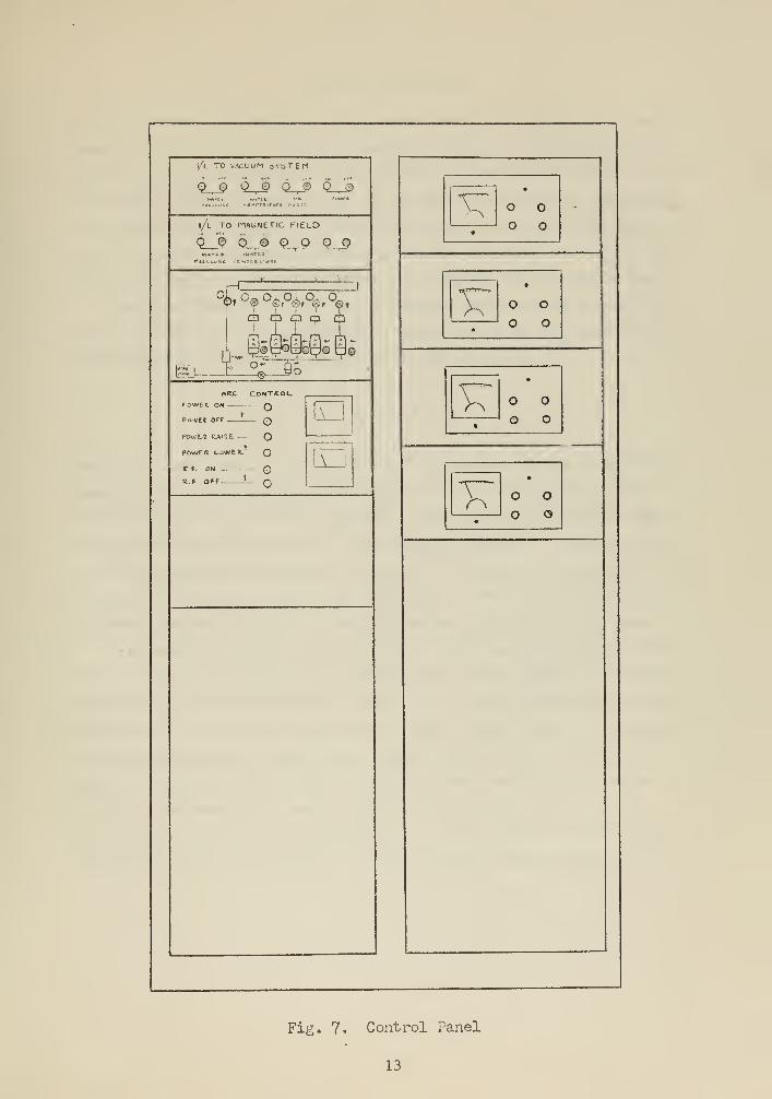
Block diagrams and wiring detail of the control and interlock cir-
cuits are presented in Figs. 4,5 and 6. Fig* 7 is a sketch of the con-
trol panel.
SVi 1 THROUGH ~l D PST
^_ TO T V 91 S-l<»
to t.b mi 1--1
a. Switch and Indicator Circuit for Gate Valves
t —
OPswiri
! I JO. P o P
S\N *3D P
SW * «O PJIN* S
D '
SW «6* 5\N I TMKOl/CW £ OPiT
TO T 6 «2 /-fe
p. TO TE> BZ. 1-IZ
b. Diffusion Pump Heater Switch and Indicator Circuit
,(6f?) (ON) (OFF
WATtK PRESSURE
(ON ] (OFFc
WATER TEMPERATURE
_^ "O TB »3-l
_». TO TB «*3-l
ON ) (OFF]
IrtCLAV <T4
P.IR PRESSURE
*KL.Y#l-4 HO* AC. DPOT
. TO T 8 «5 5-6
c. vacuum system Interlock Indicator Circuit
POWER* COMTTOL R F CONTROL POWte. tfllSE-LOWEC
± *-
+_ TO TO » 4- ,-
-*-4-fe S.«» 3I
2- OPDT CENTER OFF5WHI HPDT
d. Arc Control Panel and Indicator Circuit
Fig. 4. Main Control Console V/iring - Block Diagram
10

100"40 »
p» t
+ •-
40»
ei_£^r«00C COOLlNfc i/l
r\> h-
CATHODE ANODC Floating fsmode
TO AK.C CONTROL PAIȣL
a. Jchematic. Plasma oource Power
T
(J) INifSU «YAT£ri TtMP. RELAY
AT THti ,'OIMTSW »l DI-DT CEMTEIt OPF
ONTO TO *^ o-
I -S
O <$-
5EL-REK rowew ukit
ON-OTF P.B.
ON OFF
r^ U
b. ,,rc Control Panel - Power on-off
l^£LAY £SPOT
&~
—O TO. »4- 4-6
c. Arc Control Panel - rf on-off
TO T S *« 7-IO
LEAGCO TO
|~TC
t/Alll «i in
i : _SEL-KEX OMIT
rc*Ei surfLV "*
CONTHOL UW/T
d. Arc Control Panel - Power raise-lower
Fig. 5. Power supplies and Discharge Control - Wiring Details
11
n/RrErt pnE.«u«re switch
TO RIR THeSSUKE SWITCH,LOCKOUT klv,
AMD fliX OP PMUtR RELAVi
« RIR rfcESMJRe iNTCRLOCK.
CIRCUIT li IDfeWTlCftL.
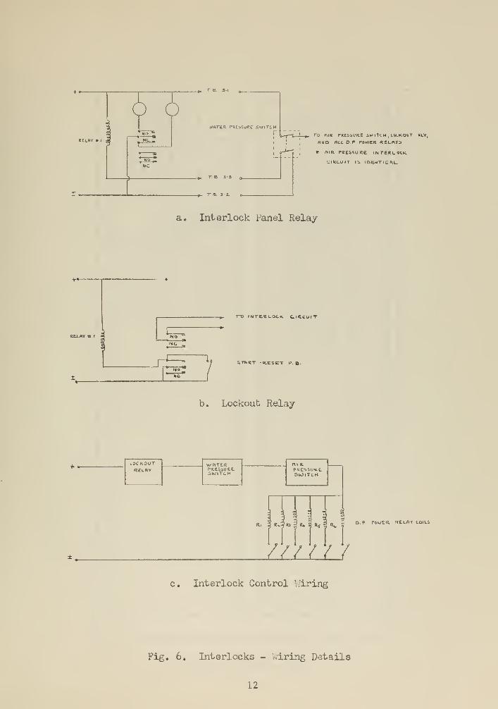
a. Interlock Panel Relay
NOIMC
_^. T-O INTERLOCK CIRCUIT
-J STORT R.ESCT P. B.
b. Lockout Relay
*»- LOCKOUTRELBV
whteitPdESSUKeSWITCH
PRE^SUKtSlOlTcH
R.. 3 R\.-* RJ"
o S o a » 3 o p comEU telsy cons3 s* •3 R5? % 5
//////c. Interlock Control Wiring
Fig. 6. Interlocks - Wiring Details
12
\/t TO VACUUM aVSTEM
o_3 o_J> Q-J> <*L£
i/l to magnetic field
Q_J> Sji 9^9 99
°9^13 fl Q
[p©p@o06O-—
®
_yo
«kc controlFOXVft on QPME« OFF . QPOwLS fcAISE— OPOw/fR UWtB. OC F. CN QR F OFF- I
lA !
m
T7*
o o
o•
^ o o' o o
vT ° °
—;' O O
r^o o
o o
Fig. 7. Control Panel
13
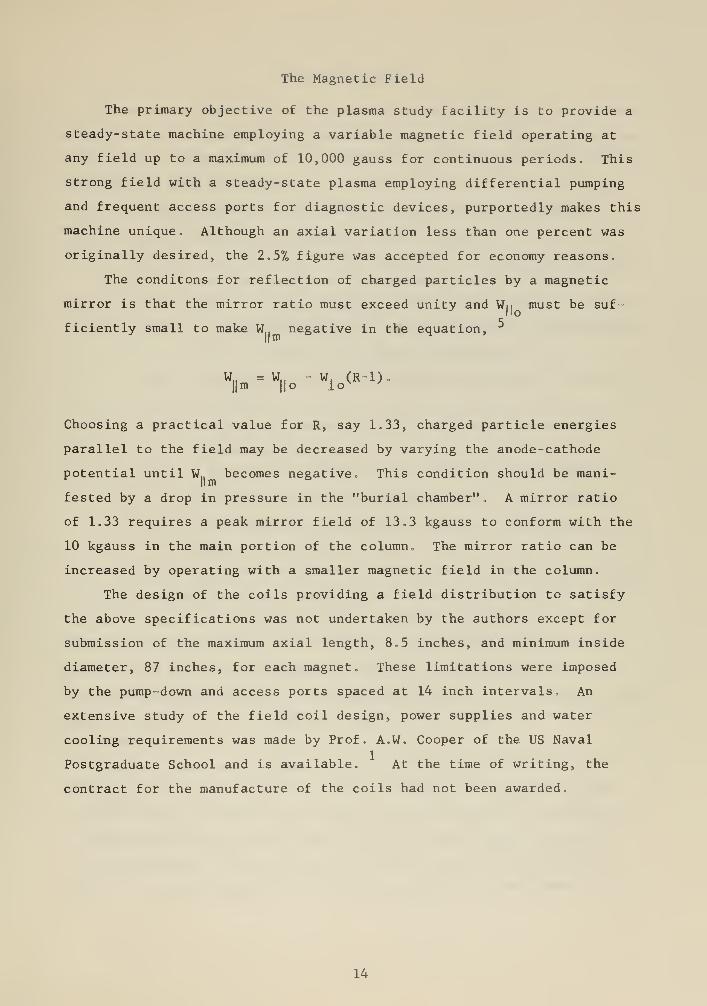
The Magnetic Field
The primary objective of the plasma study facility is to provide a
steady-state machine employing a variable magnetic field operating at
any field up to a maximum of 10,000 gauss for continuous periods. This
strong field with a steady-state plasma employing differential pumping
and frequent access ports for diagnostic devices, purportedly makes this
machine unique. Although an axial variation less than one percent was
originally desired, the 2.5% figure was accepted for economy reasons,
The conditons for reflection of charged particles by a magnetic
mirror is that the mirror ratio must exceed unity and Wn must be suf-
ficiently small to make W negative in the equation, 5
W.. = W„ - W, (R 1) .
||m || o lo v'
Choosing a practical value for R, say 1.33, charged particle energies
parallel to the field may be decreased by varying the anode-cathode
potential until W n becomes negative. This condition should be mani-II m
fested by a drop in pressure in the "burial chamber". A mirror ratio
of 1.33 requires a peak mirror field of 13.3 kgauss to conform with the
10 kgauss in the main portion of the column. The mirror ratio can be
increased by operating with a smaller magnetic field in the column.
The design of the coils providing a field distribution to satisfy
the above specifications was not undertaken by the authors except for
submission of the maximum axial length, 8.5 inches, and minimum inside
diameter, 87 inches, for each magnet. These limitations were imposed
by the pump -down and access ports spaced at 14 inch intervals. An
extensive study of the field coil design, power supplies and water
cooling requirements was made by Prof. A.W. Cooper of the US Naval
Postgraduate School and is available. At the time of writing, the
contract for the manufacture of the coils had not been awarded.
14
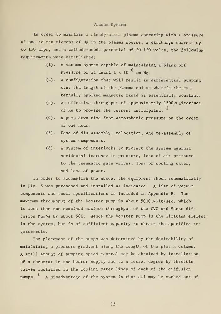
Vacuum System
In order to maintain a steady state plasma operating with a pressure
of one to ten microns of Hg in the plasma source, a discharge current up
to 150 amps, and a cathode anode potential of 20 120 volts, the following
requirements were established:
(1) . A vacuum system capable of maintaining a blank off
pressure of at least 1 x 10 mm Hg
(2) . A configuration that will result in differential pumping
over the length of the plasma column wherein the ex-
ternally applied magnetic field is essentially constant,
(3). An effective throughput of approximately 1500^ Liter/sec3
of He to provide the current anticipated.
(4) . A pump-down time from atmospheric pressure on the order
of one hour,
(5) . Ease of dis- assembly, relocation, and re-assembly of
system components.
(6) . A system of interlocks to protect the system against
accidental increase in pressure, loss of air pressure
to the pneumatic gate valves, loss of cooling water,
and loss of power.
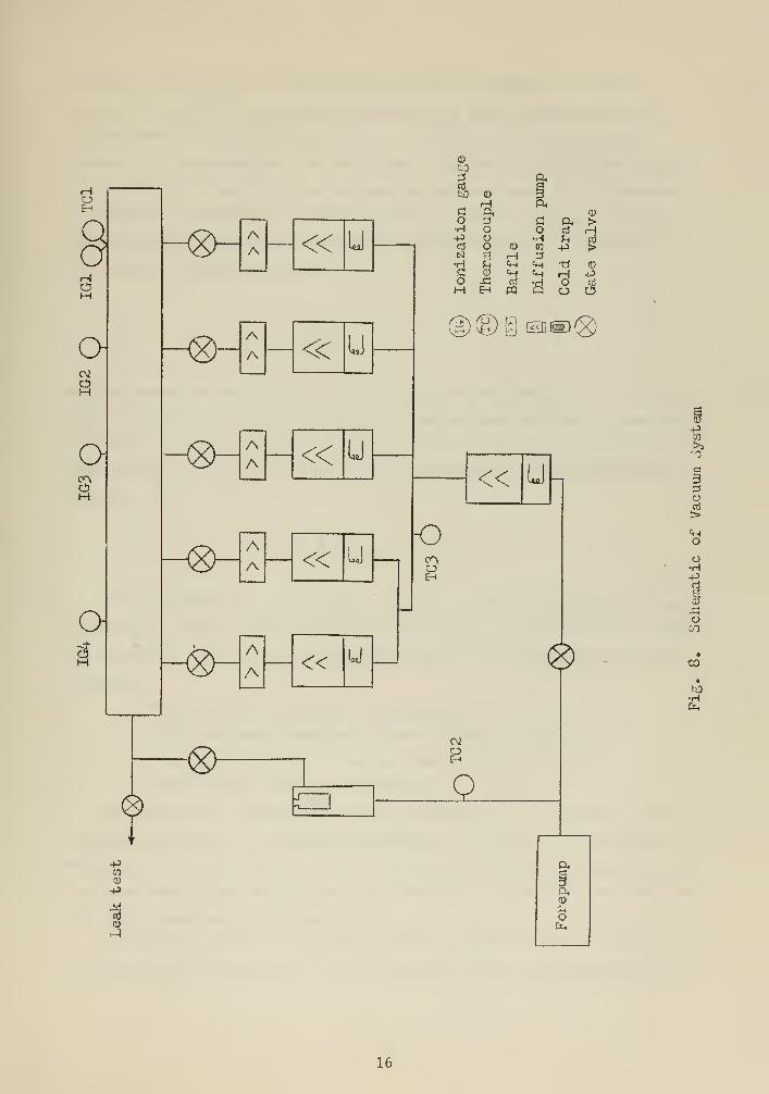
In order to accomplish the above, the equipment shown schematically
in Fig. 8 was purchased and installed as indicated. A list of vacuum
components and their specifications is included in Appendix B The
maximum throughput of the booster pump is about 5000y<M.lit/sec, which
is less than the combined maximum throughput of the CVC and Veeco dif-
fusion pumps by about 587o. Hence the booster pump is the limiting element
in the system, but is of sufficient capacity to obtain the specified re-
quirements .
The placement of the pumps was determined by the desirability of
maintaining a pressure gradient along the length of the plasma column.
A small amount of pumping speed control may be obtained by installation
of a rheostat in the heater supply and to a lesser degree by throttle
valves installed in the cooling water lines of each of the diffusion
pumps. A disadvantage of the system is that oil may be sucked out of
15
<8>-
o-
OM
o
A « u
to
to
o•H-PniN•HflO
)-AA « W)
h-AA « U
CD
H
Ooo
CD
-CEh
td
PQ
a,
p,
o•rlCO
«H
a >crt H^ cr!P >TJ VH PO £O O
pjisj em®
oo
oEn
J- Q.
-p
0)
-p
-1
-pCO
o
oo•H-P
CD
-GO
to
y&H
16
one pump into another through the glass vacuum chamber. A solution
would be to provide a manifold connecting the input sides of the dif
-
fusion pumps. Boron nitride baffles are inserted in the vacuum
chamber to compartmentize the system and to promote differential pumping.
In order to make high vacuum pumping calculations, it is necessary
to ascertain the speed of the CVC baffe-Veeco diffusion pump combination.
(CVC baffle CVC diffusion pump speeds are made available by the manu-
facturer,) Using the formula,
1 _ 1 j_C ~ S
"SP
8 9and the speed characteristic curves of the two manufactures, ' it is
found that the throughput of the CVC diffusion pump and baffle combination
is about 1.45 times as great as for the Veeco diffusion pump and baffle
combination, ' In order to obtain the conductances of the plumbing, the
, - 10formula,
C = 0.25 S p (y*. lit/sec)
was used where D is in inches, 1 in feet, and p, the mean pressure,
in microns, After inserting correction factors to allow for elbow bends,
the following operating pressures were found to be compatible with the
equipment:
Forepressure to booster: 164 microns,
Inlet pressure immediately above booster: 98 microns.
Operating pressure in vacuum chamber: 5 microns,
For further details see Appendix B.
By bleeding He through the hollow cathode at 219 cc/min at 30 psia,
the above pressure and throughput conditons can be met. A Fischer and
Porter tri-flat variable area flow meter is to be used for measuring He
flow rate and a Hoke vernier valve for metering. Blank-off is maintained
by a Veeco high-vacuum bellows valve.2
The inside area of the vacuum chamber is about 25 ft. Using the
CVC high vacuum calculator, it can be shown that the system could easily
17
pump down to 10 mm Hg under ideal conditions in a one hour period.
Approximately three hours will be required to reach a vacuum in the
order of 10 mm Hg
.
The following interlocks are integrated into the vacuum system.
A water-pressure actuated switch located in the cooling water line is
provided to close the gate valves and disconnect the heater power supplies
to the diffusion and booster pumps. This will prevent the oil from back-
streaming into the vacuum chamber and cracking because of excessive heat.
The gate valve solenoids are constructed to close when power is lost.
However, it is noted that a 15 psi air pressure differential is required
to close the valve. Hence an air pressure actuated switch is provided
to cut off the heater power to the booster and diffusion pumps when the
pressure to the pneumatic gate valves drops below 60 psig. As a result,
backstreaming due to a malfunction concurrent with air-pressure loss will
be minimized. In addition, the thermo-couple #1 circuit is modified so
that when the system pressure accidentally exceeds 100 microns, the gate
valves will close.
Flat rubber gaskets are used throughout the system except where
rings and 0-ring grooves were provided by manufacturers for seals in
their equipment. Viton gaskets are used in the vacuum chamber and neo-
prene elsewhere. All gaskets were massaged with Apiezon vacuum grease,
type T, and the excess wiped off. To insure solid flange contact with the
gasket, a sealing surface was raised .03 inches on one flange face and
ground to a #2 finish.
Figs, 4,5, and 6 present the block diagram and wiring details of the
control and interlock circuits.
18
Mechanical Structure
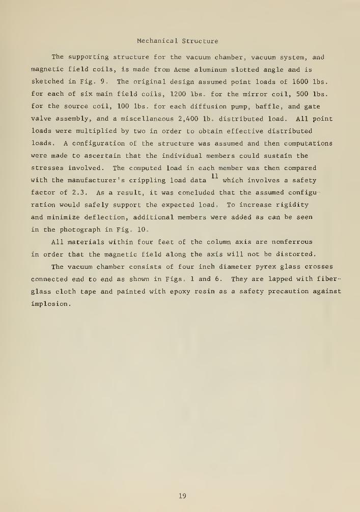
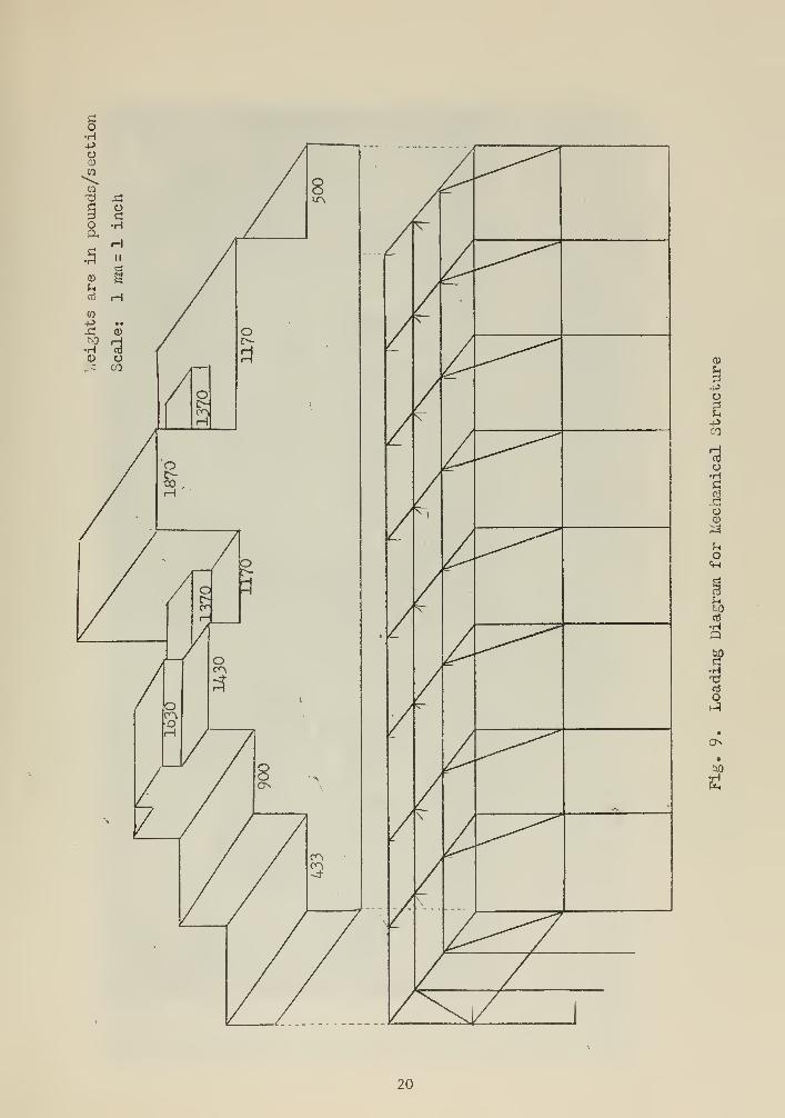
The supporting structure for the vacuum chamber, vacuum system, and
magnetic field coils, is made from Acme aluminum slotted angle and is
sketched in Fig. 9, The original design assumed point loads of 1600 lbs.
for each of six main field coils, 1200 lbs for the mirror coil, 500 lbs.
for the source coil, 100 lbs. for each diffusion pump, baffle, and gate
valve assembly, and a miscellaneous 2,400 lb . distributed load. All point
loads were multiplied by two in order to obtain effective distributed
loads. A configuration of the structure was assumed and then computations
were made to ascertain that the individual members could sustain the
stresses involved. The computed load in each member was then compared
with the manufacturer's crippling load data which involves a safety
factor of 2.3. As a result, it was concluded that the assumed configu-
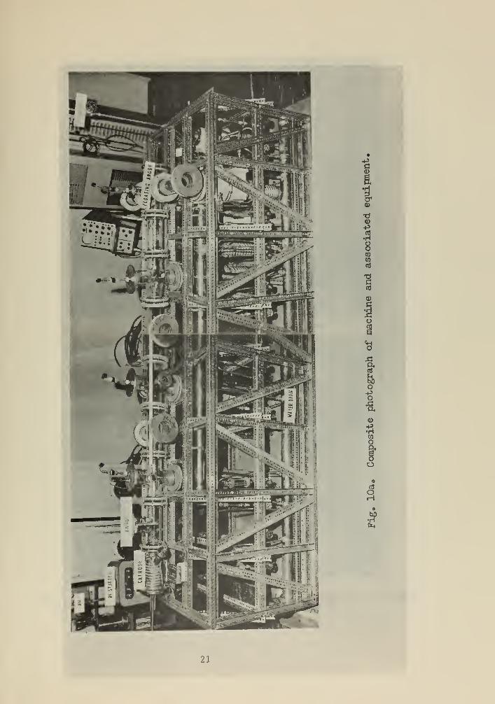
ration would safely support the expected load„ To increase rigidity
and minimize deflection, additional members were added as can be seen
in the photograph in Fig, 10,
All materials within four feet of the column axis are nonferrous
in order that the magnetic field along the axis will not be distorted.
The vacuum chamber consists of four inch diameter pyrex glass crosses
connected end to end as shown in Figs, 1 and 6. They are lapped with fiber-
glass cloth tape and painted with epoxy resin as a safety precaution against
implosion.
19
a>
ud-podU-PCO
o•HC
oCD
Ocm
Ito
•H3
T3
O
O•tsO
•H
20
1a*CD
to(0
nJ
a,
O-Po
a>
CO
o§o
a
aaH
X
21
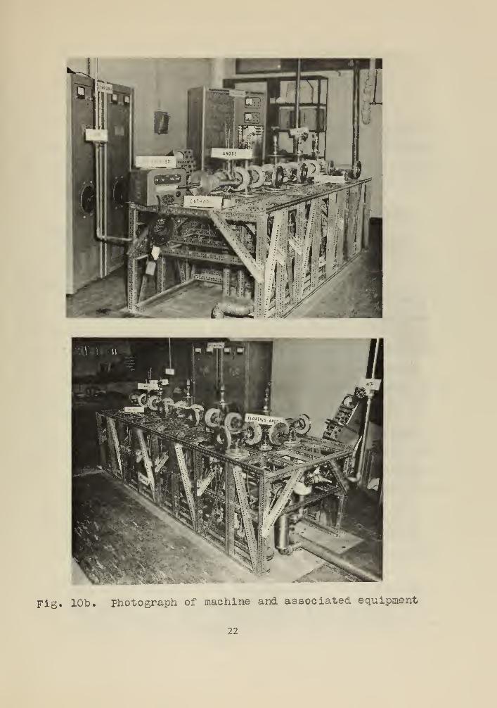
Fig. 10b. photograph of machine and associated equipment
22
Appendix A
Operating Instructions and Recommendations for Future
Modifications
The operating instructions included in this appendix are presented
to enable personnel unfamiliar with the system to obtain a vacuum and
establish a plasma. Following the operating instructions is a list of
recommendations to improve the efficiency of the vaccum system if de-
sired.
Obtaining a Vacuum :
1. Blow down high pressure air line to remove moisture,
2. Ensure presence of water-cooling flow to the fore pump,
3. Open the air pressure valve charging the pneumatic gate valve lines,
(The air pressure line is interlocked such that pressures below 60
psi will cut out heater power to the booster and diffusion pumps,)
4. Fill the liquid nitrogen trap.
5. Start the fore pump with gate valve V6 open and all others closed.,
This will "rough-down" the vacuum chamber. Note that the open
position on all valves is indicated by a light on the control panel,
6. When thermocouple TCl reaches 100/<. , close V6 and open V7 . This
pumps out the booster and diffusion pump fore- lines.
7. When TC3 reaches 100y<^ , open valves Vl through V5 , This enables
fore pump "rough-down" of the entire system. Interlocks will pre-
vent these gate valves from opening (except V5 which is manually
operated) unless TCl reads less than lOO^u . In this event, further
"rough- down" through V6 would be necessary,
8. Ensure that water cooling to the booster pump boiler is off by
positioning the cooling valve handle in the horizontal position.
Blow out the remaining water in the boiler cooling line with com-
pressed air.
9. Turn on cooling water to all vacuum equipment, A water pressure
tap located in the output side of baffle, Bl, actuates a switch
which will close all the pneumatic gate valves and disconnect the
23
heater power supplies to the booster and diffusion pumps in the event
of low water pressure
,
10. When TCl and TC3 again reach 100/t, energize the booster heater
.
Steps three through seven and nine are pre requisite to this step
because of interlock switching in the heater circuits,
11. Allow eight minutes for the booster to reach steady-state conditions
and then energize the heaters on the diffusion pumps. The "on" condi-
tion for all heaters is indicated by lights on the control panel,
The above remark concerning interlocks in step 10 applies. It
should take less than one hour to pump down to 10 mm Hg and about
three hours to 10 mm Hg in the chamber,
12. Energize the ion gauges when the system pressure is less than one
micron
.
13 o As the manual gate valve, V5, could not be integrated into the inter-
lock system, it should be closed and the ion gauges de-energized
whenever the system is left unattended. With these exceptions, the
system may operate continuously. It is not necessary to maintain the
liquid nitrogen supply in the coldtrap except when roughing down
through valve, V6.
Obtaining a Plasma :
1. Obtain a magnetic field of 200 gauss in the cathode region using the
cathode source coil.
2. Apply 100 volts cathode-anode potential by use of the off -on switch and
momentary raise-lower switch on the arc control panel. The raise- lower
switch controls a motor which mechanically drives the rheostat in one
of the two Sel-Rex rectifiers connected in series. As the maximum
voltage output in either one of these is 60 volts, the other rectifier
must be controlled manually to achieve changes in potential greater
than 60 volts.
3. Establish a radio-frequency field in the cathode region. The intensity
of the rf is preselected on the Airco rf starter unit, The fre-
quencies generated by the spark-gap generator within the unit cover a
wide band and are inherent in the unit. The on-off switch is brought
24
to the control console for remote operation,, As the cables carrying
the rf make an effective transmitter, the rf should be applied for
as short a time as possible. The operator should be aware of the
Federal Communication Commission's regulations concerning this type, . 12
of equipment
.
4. The installation of the cooling water system to the electrodes is
such that water will flow through the electrodes whenever water is
flowing through the vacuum system components, The temperature of
water leaving the cathode is monitored and actuates a switch cutting
out the arc supply under excessive heating conditions
.
Recommendations for Future Modifications :
1. Speed control of each individual diffusion pump is desirable to opti-
mize the differential pumping scheme. A certain amount of control
can be obtained by throttling the cooling water around the diffusion
pump heaters and by inserting rheostats in the heater supplies. Valves
are installed for this purpose. Addition of the rheostats would en-
able further control.
2. The pressure tap for the cooling water pressure interlock is located
in the component furthest away from the water main input . Hence a
drop in the building water main pressure would cause the interlock
to function, A clogged up cooling line in any system component would,
if anything, cause an increase in pressure at the pressure tap and
the interlock would not function. Loss of water to a diffusion pump
without interlock action would assuredly contaminate the system,
Therefore, it is highly recommended that flow meters of the turbine
type with electrical outputs should be installed in each diffusion
pump cooling line causing the associated gate valve to close for loss
of water pressure. Time involved in cleaning a dirty system should
compensate for the extra cost. This would also provide a continuous
and accurate determination of flow in these lines.
3. To obtain a better blank -off pressure (10 mm Hg) in the vacuum
chamber, liquid nitrogen in place of water should be used to cool the
baffles o This would involve a liquid nitrogen consumption of two
lit/hr for the five baffles during equilibrium conditions,
25
4. Faster speeds can be obtained by replacing the present booster with
an NRC Booster Diffusion pump type B 6 or its equivalent. Through
puts of approximately 40,000 ^/clit/sec are possible with this type
14pump.
26
Appendix B
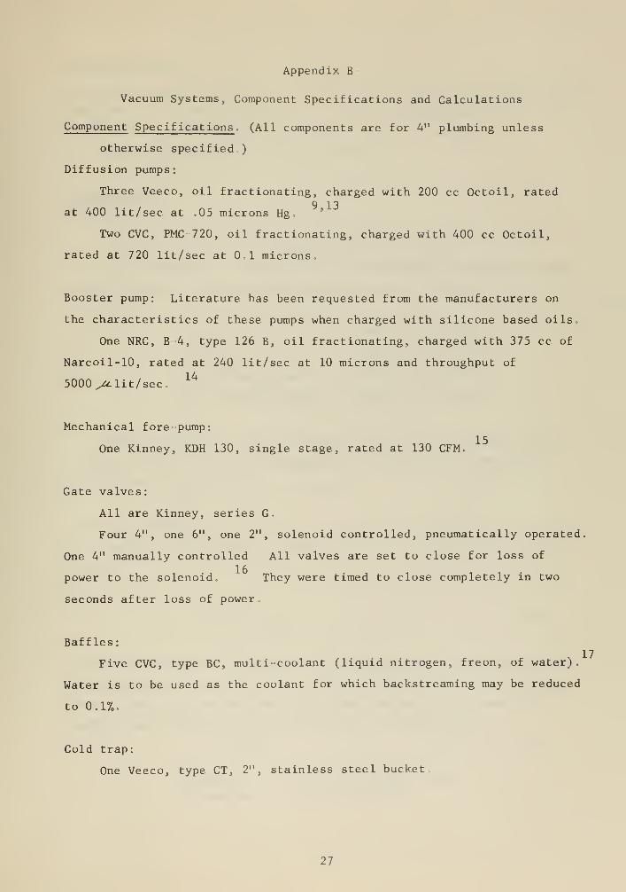
Vacuum Systems, Component Specifications and Calculations
Component Specifications , (All components are for 4" plumbing unless
otherwise specified,)
Diffusion pumps:
Three Veeco, oil fractionating, charged with 200 cc Octoil, rated9 13
at 400 lit/sec at .05 microns Hg. '
Two CVC, PMC 720, oil fractionating, charged with 400 cc Octoil,
rated at 720 lit/sec at 0,1 microns,
Booster pump: Literature has been requested from the manufacturers on
the characteristics of these pumps when charged with silicone based oils
One NRC, B 4, type 126 B, oil fractionating, charged with 375 cc of
Narcoil-10, rated at 240 lit/sec at 10 microns and throughput of
5000 yU. lit/sec,14
Mechanical fore-pump:
One Kinney, KDH 130, single stage, rated at 130 CFM.
Gate valves:
All are Kinney, series G.
Four 4", one 6", one 2", solenoid controlled, pneumatically operated
One 4" manually controlled All valves are set to close for loss of
power to the solenoid,
seconds after loss of power
1 ft
power to the solenoid. They were timed to close completely in two
Baffles:
Five CVC, type BC, multi-coolant (liquid nitrogen, freon, of water).
Water is to be used as the coolant for which backstreaming may be reduced
to 0.17o,
Cold trap:
One Veeco, type CT, 2", stainless steel bucket
27
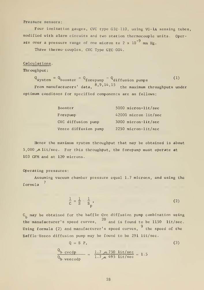
Pressure sensors:
Four ionization gauges, CVC type GIC 110, using VG-lA sensing tubes,
modified with alarm circuits and two station thermocouple units, Oper-
ver a pressure range of one micron to 2
Three thermo couples, CVC Type GTC 004.
-9ate over a pressure range of one micron to 2 x 10 mm Hg
Calculations ,
Throughput:
"'system "' ^booster ^forepump ^diffusion pumps
From manufacturers' data, ' ' ' the maximum throughputs under
optimum conditons for specified components are as follows:
Booster 5000 micron-lit/sec
Forepump 42000 micron lit/sec
CVC diffusion pump 3000 micron-lit/sec
Veeco diffusion pump 2250 micron-lit/sec
Hence the maximum system throughput that may be obtained is about
5,000 ^M- lit/sec. For this throughput, the forepump must operate at
103 CFM and at 120 microns.
Operating pressures:
Assuming vacuum chamber pressure equal 1.7 microns, and using the
7formula
i „ I . I (2)CSS' K }
p
C may be obtained for the baffle-Cvc diffusion pump combination using20
the manufacturer's speed curves, and is found to be 1150 lit/sec.9
Using formula (2) and manufacturer's speed curves, the speed of the
Baffle-Veeco diffusion pump may be found to be 291 lit/sec.
Q - S P, (3)
% cvcdp 1.7 >c750 lit/sec
Q, A l.lit 495 lit/sec=
^b veecodp ^
28
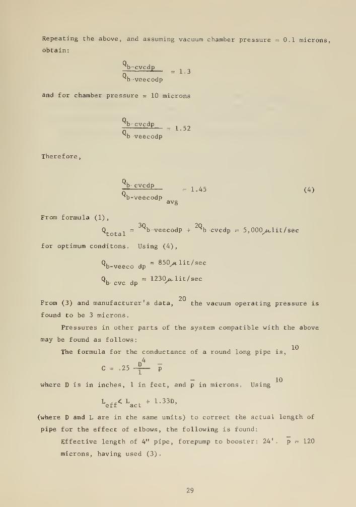
Repeating the above, and assuming vacuum chamber pressure - 0.1 microns,
obtain:
b-cvcdp=1.3
xb-veecodp
and for chamber pressure = 10 microns
^b cvcdpl 52
^b veecodp
Therefore,
l
h CVCdp= 1.45 (4)
^b-veecodpavg
From formula (1),
Q , = b-veecodp + % cvcdp = 5,000^/clit/sec
for optimum conditons. Using (4),
Q, , = 850>t lit/secb-veeco dp ^
Q, . = 1230 /«, lit/ secb- cvc dp ^
20From (3) and manufacturer's data, the vacuum operating pressure is
found to be 3 microns.
Pressures in other parts of the system compatible with the above
may be found as follows:
The formula for the conductance of a round long pipe is,
C .25 -Si. p
where D is in inches, 1 in feet, and p in microns, Using
L „< L _ + 1.33D,eff act
(where D and L are in the same units) to correct the actual length of
pipe for the effect of elbows, the following is found:
Effective length of 4" pipe, forepump to booster: 24'. p = 120
microns, having used (3)
.
29
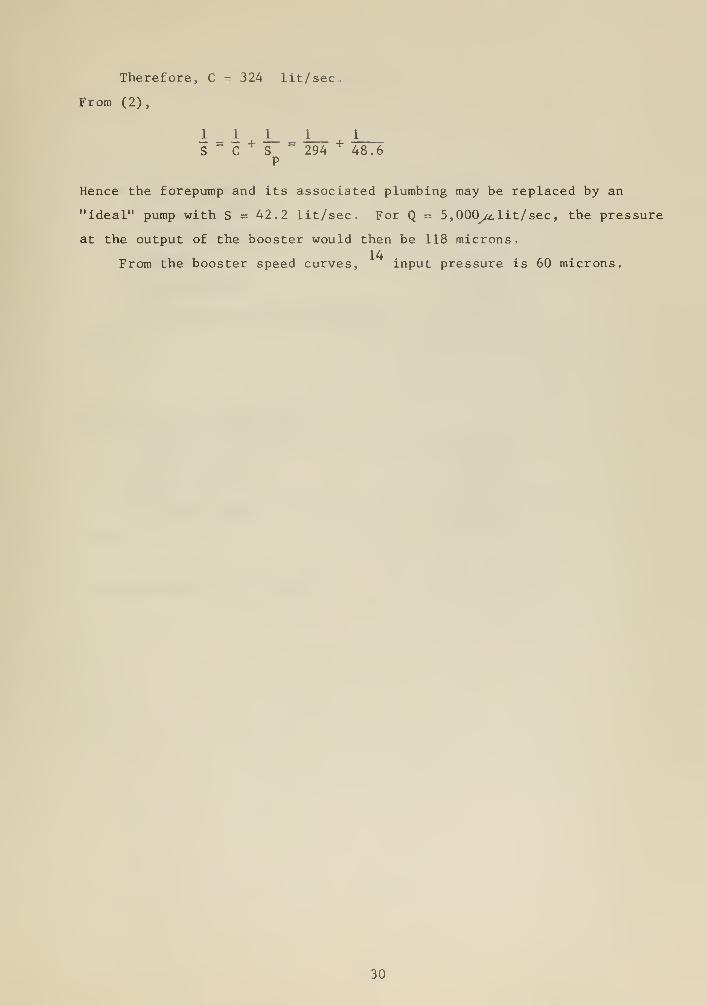
Therefore, C = 324 lit/sec.
From (2),
1 1 1_ 1_ 1
S " C+
S=
294+
48.6P
Hence the forepump and its associated plumbing may be replaced by an
"ideal" pump with S = 42.2 lit/sec. For Q = 5, 000^ lit/ sec, the pressure
at the output of the booster would then be 118 microns.14
From the booster speed curves, input pressure is 60 microns.
30
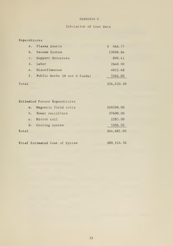
Appendix C
Tabulation of Cost Data
Expenditures
a. Plasma Source
b. Vacuum System
c. Support Structure
d. Labor
e. Miscellaneous
f. Public Works (M and funds)
Total
$ 466.77
13008.84
899.41
2640.00
4052.48
3366.00
$24,433.50
Estimated Future Expenditures
a. Magnetic field coils
b. Power rectifiers
c. Mirror coil
d. Cooling system
Total
$19290.00
37600.00
2285.00
5506.00
$64,681.00
Total Estimated Cost of System $89,114.50
31
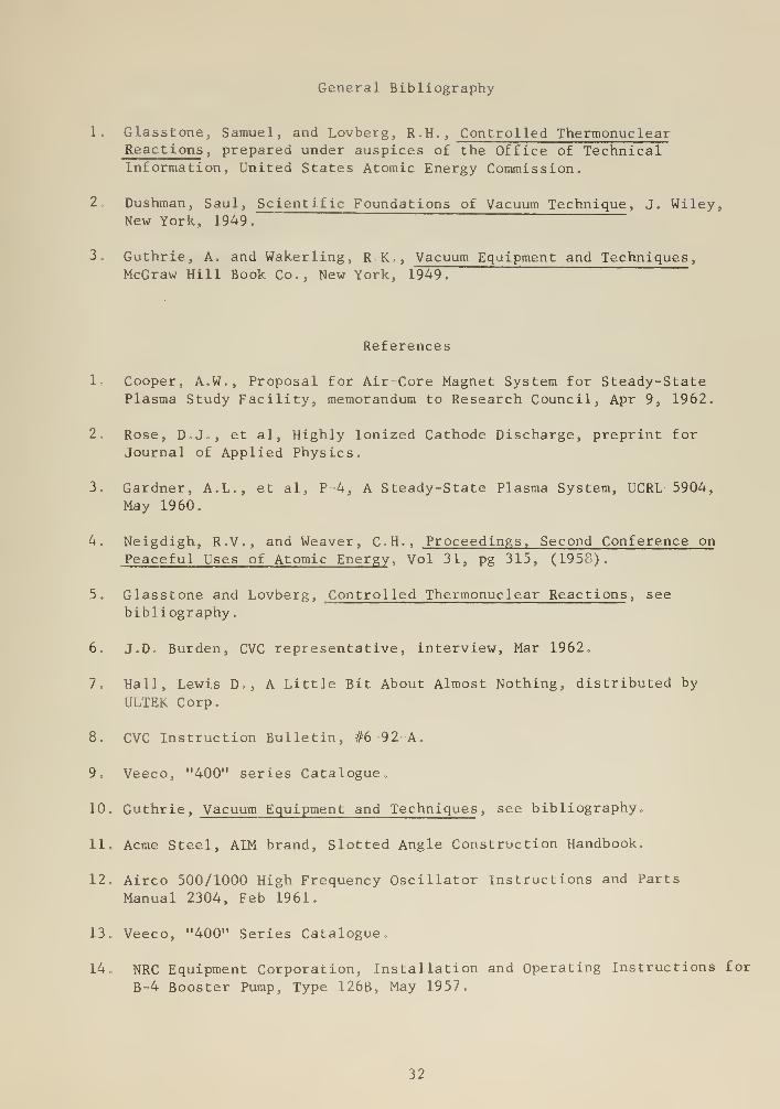
General Bibliography
1. Glasstone, Samuel, and Lovberg, R.H., Controlled ThermonuclearReactions
,prepared under auspices of the Office of Technical
Information, United States Atomic Energy Commission.
2. Dushman, Saul, Scientific Foundations of Vacuum Technique , J. Wiley,New York, 1949.
3. Guthrie, A. and Wakerling, R,K,, Vacuum Equipment and Techniques,
McGraw Hill Book Co., New York, 1949.
References
lo Cooper, A.W., Proposal for Air Core Magnet System for Steady-StatePlasma Study Facility, memorandum to Research Council, Apr 9, 1962.
2. Rose, D.J., et al, Highly Ionized Cathode Discharge, preprint for
Journal of Applied Physics
.
3. Gardner, A.L., et al, P 4, A Steady-State Plasma System, UCRL 5904,
May 1960.
4. Neigdigh, R.V., and Weaver, C.H., Proceedings, Second Conference on
Peaceful Uses of Atomic Energy , Vol 31, pg 315, (1958).
5. Glasstone and Lovberg, Controlled Thermonuclear Reactions , see
bibliography.
6. J.D. Burden, CVC representative, interview, Mar 1962,
7„ Hall, Lewis D., A Little Bit About Almost Nothing, distributed by
ULTEK Corp.
8. CVC Instruction Bulletin, #6 92 A.
9. Veeco, "400" series Catalogue,
10. Guthrie, Vacuum Equipment and Techniques , see bibliography,,
11
o
Acme Steel, AIM brand, Slotted Angle Construction Handbook.
12, Airco 500/1000 High Frequency Oscillator Instructions and Parts
Manual 2304, Feb 1961.
13, Veeco, "400" Series Catalogue,
14, NRC Equipment Corporation, Installation and Operating Instructions for
B-4 Booster Pump, Type 126B, May 1957.
32
15. Kinney Manufacturing Div,, Instructions 3120, 8J, July 1959.
16. Kinney Manufacturing Div., Instruction Bulletin #3420,8, Nov 1958
17. Consolidated Vacuum Corporation, Instruction Bulletin #10-18 B,
18. NRC Equipment Corp., Bulletin DP 5.
19. Consolidated Vacuum Corporation, Instruction Bulletin #9 -82-A.
20. Consolidated Vacuum Corp., Bulletin 6-l„
33