
7AA98 000 MASSACHUSETTS INST OF TECH LEXINGTON LINCOLN LAB FIG 17/2
SAMPLED-DATA RECEIVER DESIGN AND PERFORMANCE FOR RPSK AND MSK S--ETCIU
.L JAN 81 E J KELLY F19628 RI C 0002
UNCLASSIFIED TR-550 ES-TR-80-240 NLm IhllEEEE~lEEEEEEEEhElEElllEEElllEIIIIIIIIIIIIU~I

0Technical Report 550
0A
E.J. Kelly
Sampled-Data Receiver Design and DTICPerformance for BPSK and MSK ELECTE
Spreading Modulations . 11981)
SE
19 January 1981
Prepared for the Department of Defenseunder Electronic Systems Division Contract F19628-80-C-0002 by
Lincoln LaboratoryMASSACF1USET1S INSTITUTE OF TECHNOLO)GY
LKXIAW'o N, MAssCwUsMrs
Approved for public release; distribution unlimited.
81 4 20 099. .... I I I i I' ' -...... .. ......

p7The work reported in this document was performed at Umoln Lem y, at rfor research operated by Massachusetts Institute of Technology. This work yes spon-sored by the Department of Defense under Air Force Contact 1196284-0-C002.
This report may be reproduced to saidy needs of U.S. Government agencies.
The views and conclusions contained in this document are those of the contractorand should nort be interpreted as necessarily representing the official policies, eitherexpressed or implied, of the United States Government.
4
This technical report has been reviewed and is approved for publication.
FOR THE COMMANDER
! aimond L. Loisele, Lt.Col., US"FChief, ESD Lincoln Laboratory Project Office
Non-Lincoln RecipientsPLEASE DO NOT RETURN
Pemission is liven to destroy this documentwhen it is no longer needed.
i ii , i ii •

MASSACIIU SE'7S INSTITUTE OF TECHNOLOGY
LINCOLN LABORATORY
SAMPLED-DATA RECEIVER DESIGN AND PERFORMANCE
FOR BPSK AND MSK SPREADING MODULATIONS
F.J. KELLY
Group 4)
TECHNICAL REPOR-1 550
19 JANUARY 1981
Approved for public release; distribution unlimited.
LEXINGTON MASSACHUSETTS

Abstract
Certain spread-spectrum systems make use of waveforms built of basic
pulses spread by PN modulation of some kind. In this study the two most
common modulation waveforms, BPSK and MSK are discussed in detail. The
objective is to derive receiver structures utilizing sampled-data inte-
gration of the chips, for example, using CCD or digital correlators. A
constructive design procedure is described, together with an analysis of
performance in terms of SNR loss due to sampling. It is shown that sampling
loss can be reduced by proper choice of the prefilter which precedes the
sampling of the data.
tt
r~
CONTENTS
Abstract
Summary vi
I. INTRODUCTION 1
II. THE MATCHED FILTER 3
III. THE BPSK SIGNAL AND MATCHED FILTER 6
IV. THE MSK SIGNAL AND MATCHED FILTER 9
V. SAMPLED-DATA APPROXIMATIONS TO THE MATCHED FILTER 20
VI. CONCLUSIONS 35
APPENDIX 1 36
APPENDIX 2 38
APPENDIX 3 40
APPENDIX 4 42
v
7r -i

Summary
This report is concerned with certain aspects of the design of receivers
for two waveforms commonly used as spreading modulations in jam-resistant
communications syptems. Specifically, we are interested in the reception of
bursts, each many chips long, in which a PN code controls the modulation by
either phase changes of 1800 (BPSK) or carrier frequency shifts as in MSK.
Complex signal structures can be built on these bursts. In all cases the
signal parameters (including the code) are known to the receiver, and the
problem of interest is to optimize its design.
It is natural to base the receiver design on the matched filter
principle, insofar as this is possible with the hardware available, and one
of the features of this study is a description of the form taken by a matched
filter for waveforms of this type. The optimum receiver, as it might be
realized at base band, forms in-phase (I) and quadrature (Q) baseband signals
and passes each throug, a filter matched to a pulse shape characteristic of
the waveform. This pulse is a rectangle, one chip long, for BPSK, and
one-half cycle of a sinusoid, two chips long overall, for MSK. These outputs
are then passed through delay structures which match the chip structure of the
waveform. Each chip delay is tapped and weighted with the corresponding code
bit and summed. The final I and Q outputs are summed and thresholded for
sync detection or data demodulation.
The optimum delay structure is continuous in nature, such as a delay
line. M1nny systems use sampled data, however, either analog or quantized in
amplitude, and the sampled base-band filter outputs are then passed through a
discrete delay structure, such as a CCD correlator or a digital correlator, as
a practical approximation to the optimum structure.
In sampled-data systems of this kind, performance varies with "sampling
phase", the relative timing of the sampling device and the chip boundaries of
the actual received waveform. Pure matched filter performance is attained
only for certain values of the sampling phase, and on the average a certain
loss in performance occurs, usually expressed as a "sampling los." in
effective signal-to-noice ratio (SNR).
The sampling loss is the main concern of this study, and it is evaluated
as a function of sampling rate (number of samples per chip) for both
waveforms, using the baseband filters matched to the appropriate pulse, as
described above. However, it is also shown that this sampling loss behavior
vi
i

can be changed, often in a desirable way, by modifying the baseband filters,
and several filter designs are presented, based on different criteria for
acceptable sampling loss behavior.
The reductions in sampling loss are not great, but it is shown that the
sampling loss variation with sampling phase can be sharply reduced for BPSK,
even with one sample pe: chip, and that sampling losses with MSK sampled once
per chip can be comparable to losses with BPSK sampled at twice the rate.
These conclusions should be useful in receiver design, even though they deal
with only one aspect of that design, since sampling rates (and chipping rates)
are usually pushed as high as the technology will allow.
In addition to these details, a number of mathematical properties of MSK
are discussed, including the desirability of using one of the two tones as a
reference for demodulation to baseband.
vii
I. INTRODUCTION
Many communications systems make use of waveforms built entirely of basic
pulses, combined in ways to achieve the fundamental requirements of synchro-
nization and information transmission. Synchronization implies accurate
timing of the arrival of a reference point in the waveform, in support of
data demodulation and, in some cases, ranging. If data modulation takes the
form of pulse position modulation, then the entire task of the receiver reduces,
in a sense, to the detection and timing of the arrival of the individual basic
pulses of the waveform.
One approach to waveform design is to use intense, very short pulses, the
other common method is to increase the bandwidth of a pulse of unmodulated
carrier by modulating it. Some form of phase modulation is often preferred
because of the convenience of dealing with constant-envelope pulses.
Binary phase modulation schemes have a natural advantage in that the wave-
form itself, as well as the matched filter or correlator included in the pre-
ferred implementation of the receiver, can be neatly specified by means of a
"code", or sequence of bits. In the applications of this approach to waveform
design, the binary code is used only to spread the pulse spectrum and not to
convey information, since the code is already known to the receiver. Informa-
tion could be transferred by transmitting one of a set of codes, but this
forces the receiver to implement parallel channels, each designed to detect
one of the codes, and hence each channel is basically similar to a fixed-code
receiver, with analogous requirements on the pulses.
Two of the simplest modulation schemes which translate these ideas and
constraints to practice are binary phase shift keying (BPSK) and minimum-
shift keying (MSK). In each case the pulse is divided into a number of equal
segments, called chips, one for each code bit. In BPSK, the carrier phase
takes one of two values in each chip, according to the corresponding code bit,
while in MSK the instantaneous frequency takes one of two values, in analo-
gous fashion. In BPSK, the two values of phase differ by 1800, while in
MSK the difference of the two frequencies accumulates a phase difference of
180 over the duration of one chip.
1

This report is a study of a class of receiver structures designed to de-
tect and time basic pulses, spread by either BPSK or MSK. The chief charac-
teristic of these receivers is their use of sampled-data correlators for the
implementation of a portion of the processing, and a main objective of the
study is the optimization of the remaining portion of the receiver in order to
minimize the inherent loss in performance due to sampling. The emphasis is on
detection performance, but the results obtained are also useful in assessing
timing accuracy as well. In addition, some insight is gained into system
trade-off issues, relating sampling rate and correlator structure to perfor-
mance.
2

II. THE MATCHED FILTER
In this section we review the simple theory of the matched filter.
This will serve to establish some basic results in the general case, avoid-
ing repetition for specific waveforms, and it will also introduce some con-
ventions of notation.
The received waveform is represented as a modulated carrier:
R(t)cos[w t + 4(t)]0
and the function we deal with is the complex modulation
0~(t)Z(t) = R(t)e
This representation is not unique, of course, since the same waveform can be
expressed in terms of a different carrier frequency, as follows:
R(t)cos[w' t + V'(t)]
where
V'(t) = $(t) + (Wo - W' )t
This is a simple point, of course, but in the discussion of MSK it proves
useful to consider two such representations, with slightly different carrier
frequencies.
The real and imaginary components of Z(t) are recovered, as in-phase (I)
and quadrature (Q) signals, by beating the received signal to baseband with
a local oscillator at the chosen carrier frequency (together with a 90-degree
phase shifter to provide the quadrature reference).
The complex modulation is represented as a sum of signal plus noise:
Z(t) = Aei S(t-T) + N(t)
Here, A and a represent amplitude and carrier phase, while S(t) describes
the basic signal waveform, usually normalized to unit amplitude. The para-
meter T represents the actual signal arrival time, and N(t) describes the
complex noise. This noise is assumed to be white with the properties
3
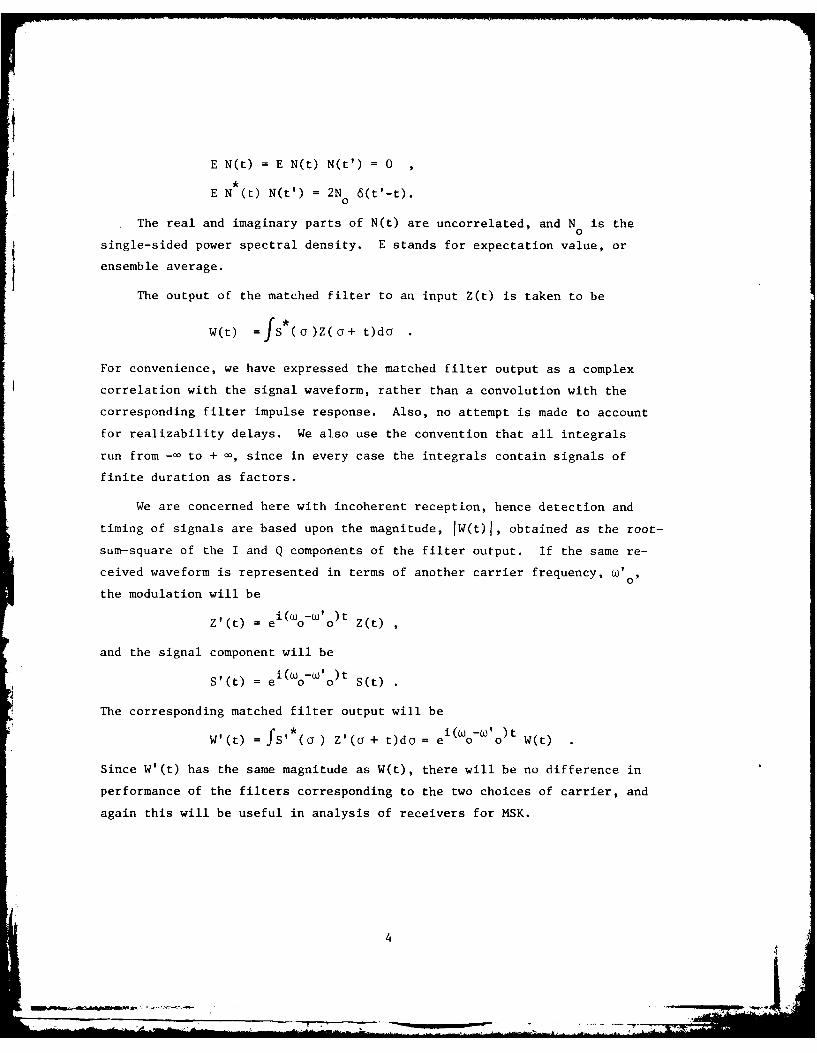
E N(t) = E N(t) N(t') = 0
E N *(t) N(t') = 2N 6(t'-t).
The real and imaginary parts of N(t) are uncorrelated, and N is the0
single-sided power spectral density. E stands for expectation value, or
ensemble average.
The output of the matched filter to an input Z(t) is taken to be
W(t) =s(a )Z(oa+ t)da
For convenience, we have expressed the matched filter output as a complex
correlation with the signal waveform, rather than a convolution with the
corresponding filter impulse response. Also, no attempt is made to account
for realizability delays. We also use the convention that all integrals
run from -- to + -, since in every case the integrals contain signals of
finite duration as factors.
We are concerned here with incoherent reception, hence detection and
timing of signals are based upon the magnitude, IW(t)j, obtained as the root-
sum-square of the I and Q components of the filter output. If the same re-
ceived waveform is represented in terms of another carrier frequency, w'0
the modulation will be
Z'(t) = e oi(Wo-'o) t Z(t)
and the signal component will be
S'(t) = ei(W o-'o)t S(t)
The corresponding matched filter output will be
W'(t) = fS'(a ) Z'(a + t)da = e i(WO o) t W(t)
Since W'(t) has the same magnitude as W(t), there will be no difference in
performance of the filters corresponding to the two choices of carrier, and
again this will be useful in analysis of receivers for MSK.
4-

I
In the absence of noise, the otitr),' .-,uid be due to signal only:
W(t) = AeimJs*(o )S(o + t - T)da
= Aei C(t - T)
where C(t) is the signal autocorrelation function:
C(t) = j ( )+ td
This output has its peak value at t=T:
W(T) = Ae iC(O)
For noise alone, the output is
W(t) =fs (o)N(o+ t)d a
a random process with autocorrelation function
EW (t) W(t') = 2N ffS()S(d)6(o+ t-o'-t')dodo'
= 2N C(t'-t)
The output signal-to-noise ratio (SNR) is defined as the ratio of IW(t)1 2 ,
for signal only, to EIW(t) 2 , for noise alone. The peak SNR, which occurs
when t=T, is
A2C0
SNR = AC(O) = Es/No'2Ns0
0
where E., the total signal energy, is
A2 A2 f 2
E = C(O) = 2A ),2
s 2 - 2-- S )1 d o .y
The signals of interest in this report are of constant envelope: IS(t)I = 1,
and of finite duration, say T, so that E = (1/2) A2 T.
In later sections we will be discussing approximate implementations of
matched filters, and their performance will be characterized by the loss in
peak output SNR, relative to E /NS 0
5f

III. THE BPSK SIGNAL AND MATCHED FILTER
The BPSK signal can be described by the modulation function
S(t) =E a P (t-nA)n on
The a are binary variables, assuming values ± 1, for n in the range 1 < n < L.
They represent some pseudorandom code, whose detailed properties are not of
interest here, except for sidelobes, as discussed below. We use the convention
that a = 0 for n < 0 and n > L, so that all sums are unrestricted in extent.n
The chip duration is A, and the basic pulse, P is defined by0
1 A< t :5A
Po(t) 2 -;2
0 ; otherwise
It is unnecessary to make any assumption about the relation between carrier
frequency and chip duration, since the analysis uses only the modulation.
In practical schemes for generation of BPSK it may be useful to work at a
carrier which is a multiple of the chipping rate, but this relation is lost
when the carrier is changed, either before transmission or in the receiver
as part of the demodulation process.
In terms of p , the normalized autocorrelation function of P
PO f Po(a ) P (o+ t)dcf
A _
0; otherwise
the BPSK signal autocorrelation function is
67

C(t) a amfPo (a- n tA)P(cY+ t- m A)d an,m
-=AECP 0 (t-2,A)
We have introduced the code autocorrelation sequence
n. n-f-n
Note that C 0 L, C_ , = C x and that, for 2k 0,
L-Z2C z E ana n
n1l
so that C.= 0 for 94I> L. For "good" code sequences, the sidelobe values
(C z for Z #0) will be small compared to L. In any case,
C(0) = AC 0P (0) = L A
which equals to signal duration, hence
1 2Es = -A L A
The matched filter processor takes a simple form, since we may write
W(t) a fP a- n A) Z(a + t)don n o
E a an Z 1(t + n A)n
where
z I(t) fJP0(c) Z(aj+ t)dcy
7
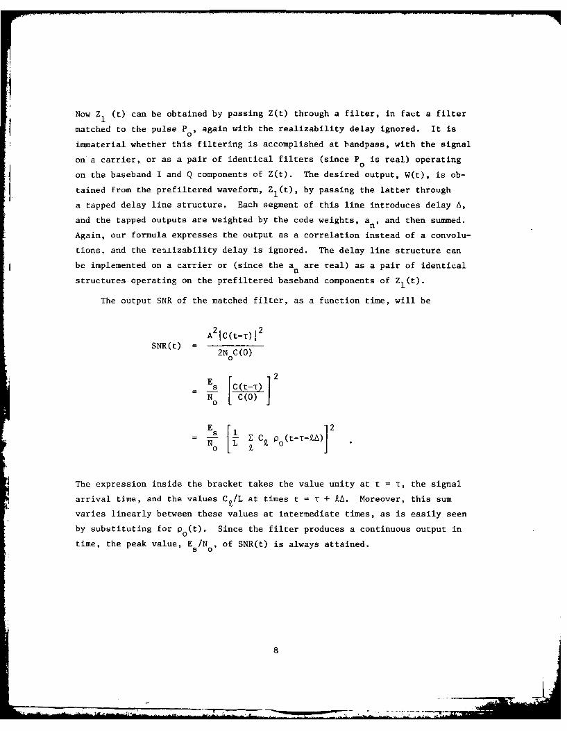
Now Z (t) can be obtained by passing Z(t) through a filter, in fact a filter
matched to the pulse P0 9 again with the realizability delay ignored. It is
immaterial whether this filtering is accomplished at bandpass, with the signal
on a carrier, or as a pair of identical filters (since P is real) operating0
on the baseband I and Q components of Z(t). The desired output, W(t), is ob-
tained from the prefiltered waveform, Z1(t), by passing the latter through
a tapped delay line structure. Each segment of this line introduces delay A,
and the tapped outputs are weighted by the code weights, an, and then summed.
Again, our formula expresses the output as a correlation instead of a convolu-
tions, and the realizability delay is ignored. The delay line structure can
be implemented on a carrier or (since the a are real) as a pair of identicaln
structures operating on the prefiltered baseband components of Zl(t).
The output SNR of the matched filter, as a function time, will be
A21C(t-T)j1SNR(t) =
2N C(O)0
E 2
- ES [C(t-t)
No [ C(O)
s 5 i C Po(t-T-ZA)N 01 L PJz
The expression inside the bracket takes the value unity at t = T, the signal
arrival time, and the values Cz/L at times t = T + ZA. Moreover, this sum
varies linearly between these values at intermediate times, as is easily seen
by substituting for p0 (t). Since the filter produces a continuous output in
time, the peak value, EsINo, of SNR(t) is always attained.
. .

IV. THE MSK SIGNAL AND MATCHED FILTER
We introduce the MSK modulation as pure frequency modulation, where
within each chip the radian frequency is either increased or decreased by a
fixed amount, v, according to the value of a code bit. The value of v is
related to the chipping rate so that the modulation produces a phase change
of ± 90 degrees over one chip. We put
ei(t) 0 < t < L A
s(t){
0 otherwise
where the initial phase, (D(O), is zero, and the instantaneous frequency is
P(t) = b V , for (n-i) A < t < nAn_
The b are binary variables representing a code sequence, and n runs fromn
1 through L. The relation between modulation frequency and chip length is
simply
vA = 2
The phase, 4(t), is a continuous function of time, which takes on the
values 4(A) = blv/2 , D(2A) = (b1+b2)r)/2, and generally
(D(nA) =(b 1 + ... + bn )w/2,
at the chip transition times. At an intermediate time the phase varies
linearly:
4(t) = 4(nA) + bn+I v(t-nA)
for n A < t < (n+l)A
9
.t
For a binary variable, b, we have the obvious identity
l b 0e fb6 cosO + i b sinO
and in particular
i b 7r/2e =ib
Therefore, the modulation function can be written in the form
S(t) = ei (bI+ ... + b n)(t/2) + i b n+v(t - nA)
. inbl...bn [cos V (t - nA) + i bn+ 1 sin v(t nA)],
for t in the range [n A, (n+l)A]. This formula holds for t in the range
[0, A] if we interpret the product b1 ... b to be unity for n = 0. We definen
the new sequences of binary variables:
a0
an b 1 -'bn < n < L
and observe that
S(t) = ina cos V (t-nA) + in+l an+1 cos V [t -(n+l)A]n
for t in the range [n A, (n+l)A] and 0 < n < L. We have used the relation
of V to A to equate sin v t to cos '(t-A)
If we define the "MSK pulse", P(t), by
tCos vt ; -Act < A
P(t)=
;0 otherwise
1010

t henS(t) n inanP(t-nA) + in+1an+lP[t-(n + 1)A]
for t in [nA,(n + l)A]. But -or t in this range, the sum can be extended:
LS =)-E P(t-nA)
n-o
since the other terms vanish by the definition of P(t). Obviously, this sum
is a correct expression for S(t) for any t in whole range [O,LA), and it serves
to represent the MSK modulation as a sum of overlapping pulses with complex
weights of a particular kind, It should be noted that the code sequence used
in this representation is not the original sequence, which is easily recovered
from the identity
b =aa ( < n <L)
This representation is so useful, both for analysis and as a model for the
'-ctual generation of MSK, that we redefine S(t) to be the value of this sum for
all t, even outside the interval [O,LA]. This means that we allow the wave-
form to depart from the constant-envelope form in the end intervals [-A, 0]
and [LA,(L + I)AI, where a single cosine-term spills over. We take the
an-sequence to be the basic code, and make one final change, by dropping the
term n - o, so that
LS(t) , in na nP(t-nA)
n-1
which vanishes outside the range [0,(L + l)A]. The envelope is unity within
[A, LA], and it is easy to see that
SlS(t) 2 dt = LA
By making this last change we gain a consistency with the BPSK formulation,
and we also use the convention that a = 0 unless 1 < n < L, so that sums
can be unrestricted in range.
If the carrier radian frequency is w,9 then the MSK waveform has an
instantaneous frequency of either + V or -v. Looked at another way,
the actual waveform presents one of two frequencies, which differ by half
the chipping rate, and our representations of the modulation refer to a
carrier which is the average of these two frequencies. Using the freedom
to change the carrier frequency to represent the same real waveform, which
was discussed in Section II, we can take one of the two MSK frequencies as
carrier, and study the resulting modulation function. It proves useful to
take the upper frequency, w + V, as the alternative carrier, for which the
modulation function will be called Z'(t). The corresponding signal modulation
is
S'(t) = e-it S(t)
since, obviously
S'(t)ei(Wo + o )t = S(t)e iot
Substituting, we find
-ivt nS'(t) = e E i a P(t-nA)
nn
= E a ne-itnA P(t-nA),
n
or
S'(t) = E a P'(t-nA)nn
where
P'(t) e-ivt P(t)
i -2ivt)1 + e -A<t <A
0 otherwise
12

It is easy to see how MSK results from this modulation. At any time,
only two sucessive terms contribute to S'(t), and if the corresponding code
bits are equal, the upper frequency results, since
P'(t) + P'(t-A) = 1.
If the bits are different, the lower frequency results because
-2ivtP'(t) - P'(t-A) = e
and this modulation converts the carrier, W + V, into the lower frequency,
The representation using S'(t) also explains a common method of generation
of MSK. It can be directly verified that
P'(t) = fH(s) P(t-s) ds
where
H(s) E eP (s)e-2 s
The proof follows easily from the expression
A/2 + A
P'(t) = e 2 vs P (t-s)ds = ve-2ivt e 2v P (a)dao JA o
-A/2 t - A2
Thus P'(t) is the response of a filter to the basic pulse P (t); the impulse0
response of the filter is H(s) (excluding the realizability delay), which
represents a filter matched to a burst, one ch,.p in duration, of the lower
frequency.
13

Using this fact, we can write
S'(t) fH(s) E an P°o(t-nA-s) dS
which shows that S'(t) can be formed by generating a BPSK waveform, using the
upper frequency and code sequence a n and passing this waveform through the
filter described by the modulation function H(s).
Both representations of MSK are useful, and they suggest different reali-
zations of the matched filter processor. In either case, the filter output
SNR is determined by the magnitude of the signal autocorrelation function.
Using the S-representation (i.e. the carrier w ), we have
C(t) = s (a)s(a + t)da
= i n aa fP(c - nA)P(a + t - mA)da
nm
= A E i Cp(t - k A)
In this formula, C Z is the code atitocorrelation, as before, and i(t) is the
normalized autocorrelation function of the MSK pulse:
(t) = -~(~J )P(a + +)do
(1 - 2 )cos Vt + - sin(vjtj) -2A < t < 2 A
0 ; otherwise.
14

Note that this function is non-zero for a time four chips in duration. Thus,
in general, many terms contribute to the value of C(t) at any given time, but
for t = 0,
C() = A Cp(O) = L A a
since p(ZA) vanishes for lj> 1, and the terms Z = 1 and Z = -1 cancel (Ck and
p(ZA) are even functions of Z) . Had we used the S'-representation (carrier
+ v), we would have found the autocorrelation function
C'(t) = e-iVtC(t)
but in either case the output SNR is
E 2SNR(t) I C(t0T)
0
for a signal with arrival time T
The matched filter structure follows exactly as in the BPSK case. Start-
ing with the S-representation, we define the prefiltered modulation functionZlI(t) :
Z1 (t) -fP( a)Z( a+ t)da
and find that
W(t) =fS(o )Z( a+ t)da
=E an i - n Zl(t + n A)
n
15

Note that Z1 (t) is formed by passing Zl(t) through a filter matched to P(t),
considering w0 to be the carrier. This can be realized as a bandpass filter
or, alternatively, the filtering could be performed on baseband signals ob-
tained using the average frequency as the reference. A problem arises in the
next step, the tapped delay line structure, since the weights, a in aren
complex. To implement this literally at baseband requires a pair of tappeddelay lines, in which the even-numbered taps from one line are weighted and
combined with the weighted, odd-numbered taps of the other line to form one
output. The remaining taps of the two lines are used to form the other output,
representing the real and imaginary parts of W(t), according to the equations
Re{W(t)} = . (-l)na2n Xl(t + 2n A) + Z(-l)na2n+iY l [t + (2n+l)A]n n
Im{W(t)} = 7 (-l)'na2 Y1 (t + 2n ') - (-l)n a2n+lXl[t + (2n+l)A],n n
where X and Y are the I and Q components of Z
Zlt) = X(t) + i Yl(t)
The same effect has been very closely approximated in a SAW structure,-
operating as a bandpass filter and delay structure, in which each element of
delay is decreased by one-fourth the local carrier wavelength to effect the
90-degree phase shifts required by the successive factors i n
Another matched filter structure results from using the S-representation,
where the received modulation is Z'(t) and the upper MSK tone is considered
to be the carrier. We immediately find that
r *W'(t) JS' (a) Z'(a+ t)da
E anZI(t + n A)n
16

where
z!(t) fp'( ) Z'(a + t)do
The delay line structure is now identical to that for BPSK, with real weights,
a , and the complexity has been shifted to the prefiltering wh.Lch produces
Z' (t). Since P' *(G)= P'(-o ), we have
z'(t) = fP'(co )Z'(t-a )do
hence Z1 (t) is obtained by passing Z'(t) through a filter matched to P'(t).
The impulse response of this filter is a sum of the two MSK frequencies.
It is easier, however, to represent this filter as a cascade of two fil-
ters, using our previous result
P'(t) = fH(s)P 0(t - s)ds
Thus Z'(t) can be passed first through the filter described by H(t), and then
through the filter matched to P (t), (or vise versa) according to
Zj(t) = JfPo(s) H(a )Z'(t - s - a) dods
All this filtering can be accomplished on a carrier, using appropriate bandpass
filters.
Since the real signal described by modulation ZI(t) and carrier w + v is
identical to the signal described by Zl(t) and carrier w , it is obvious that
the filtering operations described by P(t) in the S-representation and P'(t)
in the S-representation are identical if carried out at bandpass. Having per-
formed this bandpass filtering, we are then led to the requirement of complex
weights if we use w as I and Q reference. The second approach shows that this
problem simply goes away if the upper tone is used as reference in going to
baseband.
17
'A- - - - - ~ -

The two representations also lead to different structures if the filter-
ing is all done at baseband. Since P(t) is real, the components of ZW(t) are
each obtained from the corresponding component of Z(t), using identical filters
as noted above. However, if the incident signal is converted directly to base-
band using the frequency w + v, the resulting signals X' and Y', are the com-0
ponents of Z':
Z'(t) = X'(t) + i Y'(t)
From these we must obtain the components of ZI (t), according to the formulas
already given. If we define
a (t) f JH(o) Z' (t - ) d o
then
Z t)= fP(a)Z' (t -o )do
Since P0(t) is real, each component of Z' (t) is obtained by passing the
corresponding component of Z' (t) through a filter matched to P (t)a 0
To obtain Z'(t) requires four filters. In terms of the I and Q components:a
Z' (t) E X' (t) + i Y'(t)a a a
Z' (t) X' (t) + i Y' (t)
we have
X'(t) = fH,(O)X'(t-o)da - fH 2 (O)Y'(t -o )dco
Y'(t) = fH (a )X'(t-o )do + fHl( )Y'(t -o )d a
18
The filter impulse responses are obtained from H(c ):
H1 (O ) = v P ( ) cos(2va)
H2 (a ) = -V P (c) sin(2vo )
19

V. SAMPLED-DATA APPROXIMATIONS TO THE MATCHED FILTER
Consider the expression
W(t) = Z a Z (t + nA)n 1n
for the matched filter output, in terms of the prefiltered modulation, Zl(t).
This was derived first for BPSK, and also for MSK, when an appropriate choice
was made for carrier frequency. Suppose this output is sampled once every
seconds. The output samples are then
Wk W(k6) = an Z1 (k6 + nA)n
Obviously, if 6 = A/M, for some integer M, then the output samples depend only
on values of ZI(t) at multiples of 6, and the same output sequence can there-
fore be obtained by sampling the components of Z1 (t) at the rate 1/6, and then
implementing the sums to form the components of the Wk by discrete delay struc-
tures. The continuous delay line is replaced by a sampled-data tapped line,
such as a CCD device or digital shift register. When provided with an output
formed as a weighted sum of tapped signals, the structure is a CCD or digital
correlator. In this report we discuss only the approximation of matched filters
by such str?,ctures, limited to the use of binary weights. Note that such a
structure is a cascade of delay cells, one for each sample, and NM in number.
Only every M th cell is tapped to form the output.
Since only sampled outputs are available, there is no guarantee that a
signal component will be sampled at the moment of peak output SNR. This is
the well-known sampling loss, which we characterize by writing the SNR of
sample Wk as
SNR(Wk) = (E /N ).L
k so0 k
The largest value of Lk, which represents the implementation loss of the
sampled-data approximation, will be a function of "sampling phase", the inter-
val between the actual signal arrival time and the nearest sampling time.
20

For either BPSK or MSK, we know that the output SNR of the matched filter is
IC ( t - ) 2)
SNR(t) = (Es/No). C()
where T is the signal arrival time, and C(t) is the signal autocorrelation
function. If the sampled-data receiver uses the same prefilter to form Zl(t) ,
then
C(k6 - T, 2Lk C()
Suppose the nearest sampling time to the time of signal arrival is k 6, and0
thatk6=t+s0
with6 6
Then
L -C0j6+ s)2
ko+j C(O)
and the peak value will occur for j = 0:
= C(s)2Lk (s) C(0)12 Isl < 6/2
If we neglect the code autocorrelation sidelobes which enter into C(s)
for Isl< 6/2 (these are only the near-in sidelobes, which will be small for
codes of practical interest), we obtain
Lk (s) = 02(s)0
for BPSK, and
Lk (s) - 2(s)
0
21
_1!! .. .

for MSK. Obviously, sampling loss can be reduced by sampling at a high mul-
tiple of the chipping rate, but it is desirable to find other ways of control-
ling this loss, so that sampling rates can be as low as possible (or chipping
rates as high as possible for a given sampling rate).
Another way to control sampling loss is to depart from the prefilter asso-
ciated with the original matched filter receiver. This is reasonable, since
the discrete delay structure approximates the continuous version of the matched
filter, and it is no longer clear that the original prefilter is still optimum.
Nothing can be lost, in any case, by reopening the issue of optimization, but
we must now recognize that sampling phase enters as a parameter of performance.
Before discussing optimization criteria, we characterize the class of re-
ceiver structures to be considered. These represent a simple generalization
in which the "prefiltered modulation", ZI(t), is defined by
Zl(t) = fG( a )Z(o + t)do ,
which represents the output of some filter, described by G(o ), to the input
signal. The output sequence is defined as before, by
Wk = Z an Zl1kW + n A)n
and hence the structure is appropriate to BPSK, with G(a ) replacing P (a),
and also to MSK in the S'-representation, with G(a) replacing P'(a ). Since
performance is characterized by SNR alone, in this analysis, we first compute
output SNR for the generalized receiver, beginning with BPSK.
Expressing the input modulation as a sum of signal plus noise, we have
Z 1(t) = Aei E an g(t - T - nA) + NI(tn
where
g(t) P o)Po o+ t)da
22

and
N1 (t) - (a)N(o+ t)da
It follows that the signal component of Wk is
Ae i 6 E CZ g(k6 - ZA - T)£
We neglect the contribution of code sidelobes to this term, and put T = k 6-s,0
as before, so that the signal component of Wk +j is
LAei 8 g(j6 + s)
The covariance of the noise process, N1 (t), is easily computed:
E N (t)Nl(t') = 2N ffG(a)G*(o)6(o+ t - c' -t')dcdo'
= 2NJfG*(o')G(c' + t' -t)dO'
and hence the noise component of any output sample has mean squared value
2No0LJIG(o) 12 do
when code sidelobes are neglected as before. Combining these expressions
yields the desired signal-to-noise ratio loss
Jg(j6 + s)12
k + j ( C ) 2d c Y
Our objective now is to optimize performance by appropriately choosing
the function G(o ) which describes the prefiltering. We are free to direct
the optimization to the output sample k (i.e. put J=0), since realizability
can always be assured by the later addition of a delay. Thus G( a) will be
chosen to optimize
23
OIL_

L(s) IfG*(O )P(O+ s)dGJ
2
Lk (s2
0 AJIG( a do
If the sampling phase, s, were fixed and known, then the optimum choice wouldbe G(o ) = P (a+ s), by an obvious application of the Schwarz Inequality.
0
This is again the matched filter of course, with just the right delay includedth
in the prefilter to assure that the k sample occurs at a time of peak output.
The simplest approach to the problem of optimizing Lk_ (s) is to think of0
the sampling phase, s, as a random variable, and to replace the signal componentof Z(t) by its average over sampling phase. This has the effect of replacing
the factor P (o + s) by the average,0
6/2
P(O) - (116)fP(a+ s)ds
-6/2
in the formula for SNR. The corresponding loss factor is then
G*(O )7(o )dal2
AJ G(a )1 2 do
This factor is maximized, again by the Schwarz Inequality, by the choice
G(o) = P (o)
which implies a prefilter matched to the "average pulse", Po(a). The actual
loss function of a receiver using this prefilter is, of course,
Lk (s) = fP0 (a)P (a+ s)do12
o Af[Po (a )] 2 do
24

The impulse response of this filter is easily obtained:
60+2
G() f(/6) Po(S)ds
2 0-,
1 A+A A + 6I(.~A+6 o); A-6 < Ioj 26+= 2 oi; 2 - -- 2
0 A+6 <Io2 -
If 6 is very small, i.e., many samples per chip, the portion where G (C) varies
linearly becomes very small and G(Co approaches P (a), leading back to the
matched filter. At the other extreme, when 6 = A, G(o ) is a symmetrical
triangular function, 2A wide at the base.
The loss function for this filter is easily computed, either by direct
evaluation or by use of the relation
6s+
f (O)PC(O+ s)do = 0 o )do6
s-
Strictly speaking, Lk (s) was defined only for values of s in the range
Isj< 6/2, corresponding to SNR of the output sample with maxrjum signal. It
should be obvious from our definition, however, that s can take any value and
the loss Lko (s) will describe the SNR of a particular output sample. For ex-
ample, if 6/2 < s < 3 6/2
Lko(s) =Lko+lS- o )
which characterizes the SNR of output sample Wko + 1, etc.
25
~~~~ ~ ~ ~ ~ ~ ~ a. II |...Jl .... !" ... .. i

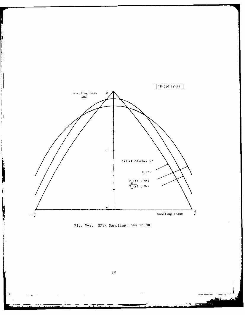
The curves of Fig. V-I show the variation of SNR with sampling phase
for this filter, for the two cases M = 1 (6 = A) and M = 2 (6 = A/2). The
curve corresponding to the original matched filter is also shown. Expanded
plots of SNR loss, in dB, are presented in Fig. V-2. Explicit formulas are
obtained in Appendix A-I.
A second approach to optimization is to choose G(o ) to maximize the aver-
age SNR, averaged over sampling phase, i.e.
6/2
Lk E Lk (s)ds0 -6/2 0
This is a somewhat more difficult problem, but an explicit solution can be
found, and a derivation is presented in Appendix 2. The corresponding filter
is almost identical to the one just derived, with almost identical performance.
Average SNR losses (in dB) are given in Table I for three filters:
"A" Filter maximizing average SNR
"B" Filter matched to average pulse Po(t), and
"C" Filter matched to the pulse P (t).0
TABLE I
AVERAGE SNR LOSS IN dB FOR THREE FILTERS
M "A" "B" "C"
1 1.70 1.82 2.672 0.78 0.80 1.194 0.38 0.38 0.57
Worst-case losses for filters "B" and "C" are as follows:
TABLE II
WORST-CASE SNR LOSSES (IN dB)
M "B" "C"
1 4.26 6.022 1.71 2.504 0.78 1.16
26

14
04 C4
4)4
00 C.
*00
434
.PO
27.
P (t) M4=20
-6
2Sampling Phase 2
Fig. V-2. BPSK Sampling Loss in dB.
28

It is also possible to design a filter which yields a loss independent
of sampling phase, for the one output sample having the largest SNR. The
penalty paid for this uniformity is a relatively large loss, as follows:
TABLE III
SNR LOSSES FOR FILTER HAVING CONSTANT LOSS (IN dB)
M Constant Loss
1 3.012 1.254 0.58
Derivation of this filter and its performance is presented in Appendix 3.
A broader class of sampled-data receivers emerges if every cell of the
delay structure is tapped, forming an output of the form
Wk = A£ ZI[(k+Z)61z
The sum would range over NM terms, corresponding to the signal duration. A
sub-class results if the weights, A, , are equal in groups of M, and corre-
spond to the code bits, so that
MWk = 7 an I ZI(k6 + nA + m )
n m=1
This output can be written
Wk = X an Z2(k + n',)n
where
M2 (kA) = M Z1 l(k + m)6]
m-I
In other words, the summation over the M terms per chip can be carried out
once and for all, ahead of the delay structure, since these terms always have
equal weight. Moreover, the same result can be achieved ahead of the sampling
step by forming
29

MZ'(t) = I Z(t + m
- m= 1
and sampling Z,(t). Finally, substituting for Z (t), we obtain
Z,(t) = o ; ) Z(o + t + m dom I
f (;2 () Z( c + t) dC2
where G ( ) ( - m
In other words, the effect of the multiple, equal-weight taps can be
achieved in the prefiltering, and hence this subclass offers no performance
aLa'1t e, since we have a Iready opt imized the pre filter. It is interesting
to note that the f il" r we obtained by matching to the average pulse, P 0( co
-II be writtel in the form of (( ) above, namely a sum of M terms, each a
di.- licod version of the simple triangle function:
of . Ivexed delay). Thus a receiver using a prefilter characterized
ci imiylk, triangular impulse response, in conjuction with a delay struc-
t in, everv cell in the special wav described above, would be exactly
i, i,,nt to the receiver we discussed earlier, with prefilter "B".
Vi . q-iace aproach to sampled-data receiver optimization can be applied
L , he inning with the gt-ieralized prefiltered modulation
/i (t) = G ( c ) Z'(C + t-) d,.
i,., ret iined the prime in our notation to emphasize the assumption of the
,r requlencv, . + v, as carrier frequency. The remaining part of the
30
-~ -w ----- _ _|-
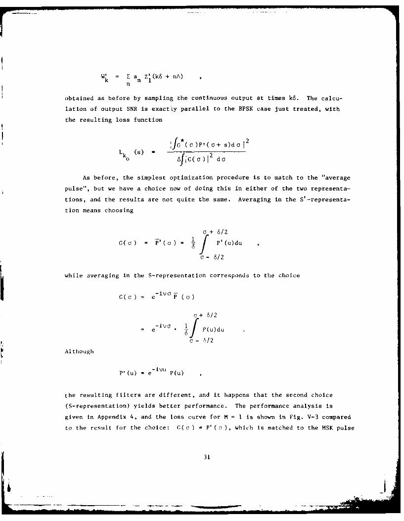
W = Ea nzj(k6 + nA)n
obtained as before by sampling the continuous output at times k6. The calcu-
lation of output SNR is exactly parallel to the BPSK case just treated, with
the resulting loss function
J*(oa)P'(o+ s)do12
Lk0 (s) = AJiG d) To G~o)I 2 do
As before, the simplest optimization procedure is to match to the "average
pulse", but we have a choice now of doing this in either of the two representa-
tions, and the results are not quite the same. Averaging in the S'-representa-
tion means choosing
o + 6/2
G(O) = P'(a) = P'(u)du
o- 6/2
while averaging in the S-representation corresponds to the choice
-ivo
G(o) = e P ( )
c+ 6/2-ivo 1 f
= e 6] P(u)du
a- 6/2
Although
P'(u) = e ivu P(u)
the resulting filters are different, and it happens that the second choice
(S-representation) yields better performance. The performance analysis is
given in Appendix 4, and the loss curve for M = I is shown in Fig. V-3 compared
to the result for the choice: G(o ) = P' (7), which is matched to the MSK pulse
31
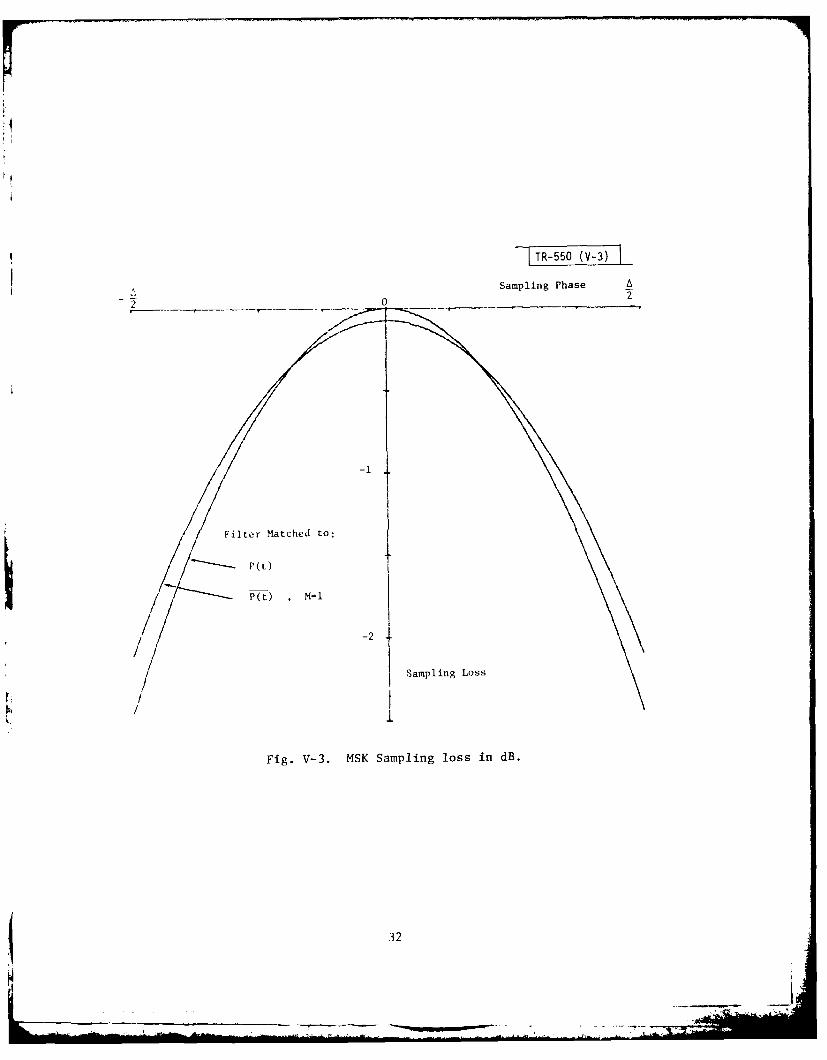
Sampling Phase
. 2 0
-i
Filter Matched to:
P(t) M=
/ -2
Sampling Loss
Fig. V-3. MSK Sampling loss in dB.
32
.- . . . . . x . ... . ..__.. . . . . __.. . . . . . .. . . .. .. . . . . . . j .. ... . . . . . . . .N . .

itself. It is seen that the results are very close, and similar curves for
M > 2 show insignificant differences between matching to the MSK pulse and
matching to an averaged MSK pulse. Average losses are shown in Table IV for
filter "B": matched to the average pulse, and filter "C": matched to the MSK
pulse itself:
TABLE IV
AVERAGE SNR LOSS FOR TWO MSK FILTERS (IN dB)
M" "C"
1 0.742 0.8252 0.204 0.2134 0.054 0.055
No explicit solutions have been obtained to the problems of optimizing
average SNR and of obtaining a constant loss function, in the MSK case. In
view of the small actual improvement of filter "B" above, relative to the
conventional choice "C", there is probably little to be gained by these other
approaches to optimization.
By the very nature of its autocorrelation function, p(t), MSK shows less
sensitivity to sampling phase than does BPSK. There is little to gain by
filter optimization, and only about 0.5 dB average improvement of double-rate
(M = 2) sampling over the single-rate (M = 1) case. This compares with a 1 dB
to 1.5 dB improvement (depending on filter choice) in the BPSK average SNR,
when going from single-rate to double-rate sampling. Worst-case SNR losses
are also milder for MSK. The following Table compares the worst case losses
of the filter "B" for BPSK (the "recommended filter", matched to an average
BPSK pulse) with "C" for MSK (the conventional MSK filter, matched to the
MSK pulse itself):
TABLE V
WORST-CASE SNR LOSSES (IN dB)
M BPSK "B" MSK "C"
1 4.26 2.442 1.71 0.634 0.78 0.16
33

We have found that the sampled-data MSK receiver uses the same discrete
delay structure as BPSK, where each cell delays by one sample, and the struc-
ture has one tap per chip. For BPSK we showed that every cell could be tapped.
with weights equal in groups of M, and the result was the same, provided a
suitable change was made in the prefilter. Specifically, the receiver with
prefilter g(c), and M taps per chip was equivalent to a receiver having one
tap pur chip and prefilter
MG(o) = E g(- m() , ( = A/M
m=l
The same result holds for MSK, since the original proof depended only on the
architecture of the receiver, and not on the signal modulation itself. For a
given receiver tapping every sample, it is easy to find the equivalent pre-
filter corresponding to one tap per chip, since we start with g( c) and find
G( c) by the above formula. It is not always easy to go the other way however,
representing a given G(a) in the form required to find g(a). It is per iaps
of interest to note that this problem can be solved for the "C" filter, since
G(a) = P'(a) =fH(s) Po(s - u) du.
We simply represent the basic pulse, P09 as a sum of M pulses, back-to-back,
each lasting one sample instead of one chip, and substitute in this integral.
The result is a representation of G(a ) in the desired form. The receiver
prefilter was factured into a cascade of two filters, with impulse responses
H(s) and P (s), hence it is only necessary to change the second from a filter
matched to a pulse one chip in duration to a filter matched to a pulse one
sample in duration. Combined with a change from one tap per chip to one tap
per cell, the result is the equivalent receiver.
34

VI. CONCLUSIONS
The two modulations discussed in this report, BPSK and MSK, are common
examples of spreading waveforms useful in a wide range of spread-spectrum
systems. A great variety of signals can be designed, using these coded pulses
as basic building blocks, hence the results of this study have a wide range of
application. Also, it appears that sampled-data receiver structures of the
kind treated here are well suited to these waveforms, where the major part of
the processing gain is achieved by coherent integration of chips in a CCD or
digital correlator.
One result of this study is a systematic method for the design of sampled-
data receivers which can easily be extended to other spread-spectrum modulations.
This method begins with the exact, continuous-time matched filter, and the dis-
crete portion of the receiver is then inferred from the requirement that its
output samples should be identical with samples of the true matched-filter out-
put. The second step of the design process is to choose the prefilter, imple-
mented at bandpass or base band in analog form, to optimize SNR performance as
a function of sampling phase.
The other result of this analysis is the design and performance of a num-
ber of prefilters for use with BPSK and MSK. The differences in performance
are not great, but the few dB they offer can in some cases be effectively
traded off against some other parameter which may be near a practical bound
in value. For example, on, would ordinarily not use BPSK with only one sample
per chip, but the fact that the 6-dB worst-case loss associated with the con-
ventional filter can be reduced to a 3-dB loss (independent of sampling phase)
might make this choice interesting in some application in which the sampling
rate cannot easily be doubled. In another case, with MSK and an unconven-
tional filter (filter "B"), double-rate sampling buys only 0.5 dB in average
SNR performance, compared to single-rate sampling, a difference which could
perhaps be achieved more easily by changing some link parameter, rather than
doubling the clocking rate of a substantial portion of the receiver hardware.
35
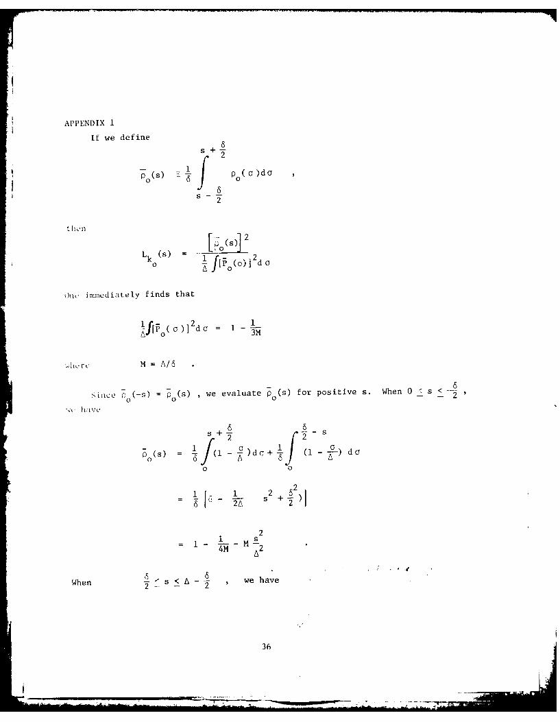
APPENDIX 1
if we define
2
pp as p)d a
2
P s2
L (S) , 0 2k lf[f/sCdo
0 ~ JP d o
Oine immediately finds that
j[(\)l 2 do -1-
A~[\) 0 3M
Sic (-s) =p (s) ,we evaluate P 0(s) for positive s. Whn0- -2'
s 6
f(2
2
P(S) o Ji-)d o + (1- doa
0 0
2 2
1 +
4M 2
When s, we have
36

s +~
2-
1 Ap S) (1 )do
2
I [A + - s - (A 2 s2 + s6 - 2~
M(s L)_
For larger s, O Cs) vanishes. Collecting the formulas:
1 - L_ _M( _j)2 0; --
< 1 d <L,!-<1A2M-A 2M
and A 2M'
L k 0Cs)=1 13M
37
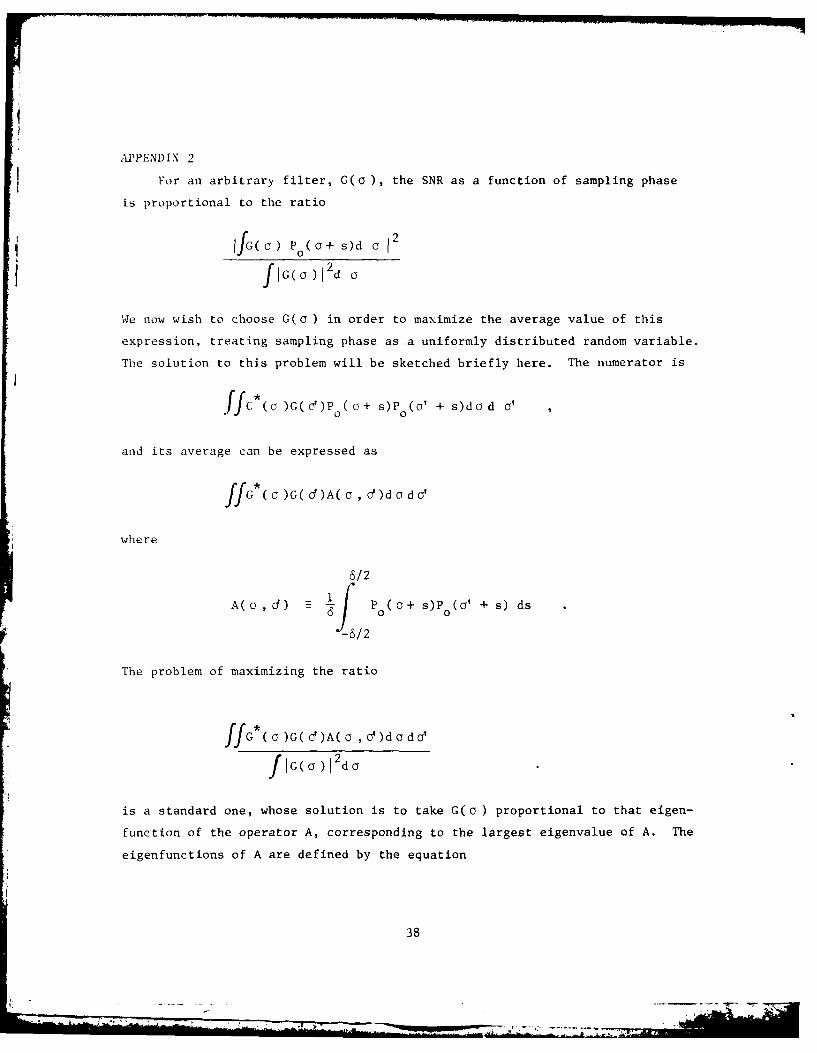
APPENDIX 2
For an arbitrary filter, G(o), the SNR as a function of sampling phase
is proportional to the ratio
IJG( o) PO(a+ s)d a 2
f G( 7) 12d a
We now wish to choose G(o ) in order to maximize the average value of this
expression, treating sampling phase as a uniformly distributed random variable.
The solution to this problem will be sketched briefly here. The numerator is
.ffc*(a )C( O')P ( G+ s)P (' + s)dod '
and its average can be expressed as
ff6 ()G(d)A(u d)do d'
where
6/2
A(, d) Po(a+ s)Po(a' + s) ds
-6/2
The problem of maximizing the ratio
ffG a )G( ()A( o , o)d a do'
JG(a )12 do
is a standard one, whose solution is to take G(a ) proportional to that eigen-
function of the operator A, corresponding to the largest eigenvalue of A. The
eigenfunctions of A are defined by the equation
38
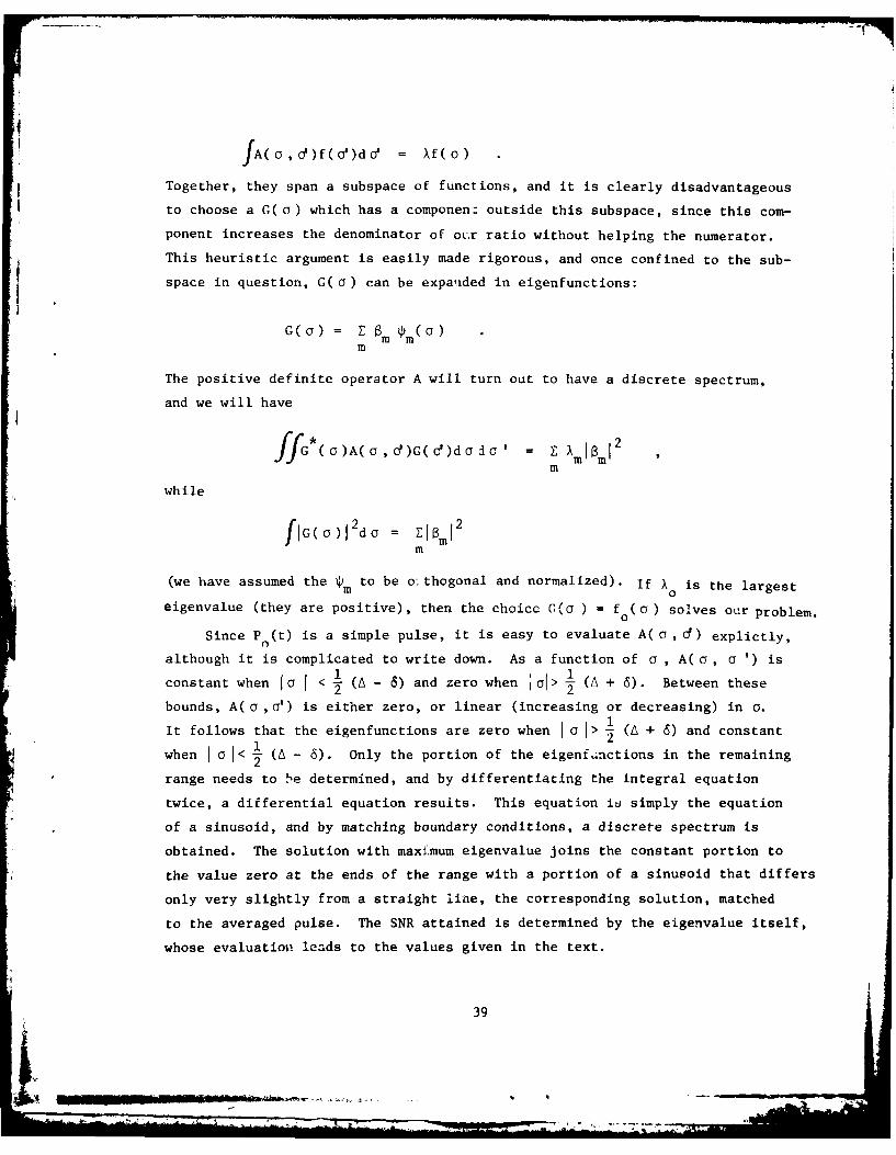
fA(C , o)f ( )da' = Xf(o)
Together, they span a subspace of functions, and it is clearly disadvantageous
to choose a G( a) which has a componen: outside this subspace, since this com-
ponent increases the denominator of our ratio without helping the numerator.
This heuristic argument is easily made rigorous, and once confined to the sub-
space in question, G(a) can be expaided in eigenfunctions:
G(G) = Z Bm m(O)m
The positive definite operator A will turn out to have a discrete spectrum,
and we will have
ffG*()A(a,d)G(d)dada' = M mIB 2
m
while
fiG(a)I2do = El~mI2m
(we have assumed the m to be o: thogonal and normalized). If Xo is the largest
eigenvalue (they are positive), then the choice G(o ) = f (a) solves our problem.
Since P (t) is a simple pulse, it is easy to evaluate A( a, d) explictly,
although it is complicated to write down. As a function of a , A( a, a ') is
constant when Ia I < - (A - 6) and zero when a01> - (A + 6). Between these
bounds, A( a ,a') is either zero, or linear (increasing or decreasing) in a.
It follows that the eigenfunctions are zero when a 0 > 1 (A + 6) and constant
when a < i (A - 6). Only the portion of the eigenfLnctions in the remaining
range needs to be determined, and by differentiating the integral equation
twice, a differential equation resuits. This equation is simply the equation
of a sinusoid, and by matching boundary conditions, a discrete spectrum is
obtained. The solution with maxi.mum eigenvalue joins the constant portion to
the value zero at the ends of the range with a portion of a sinusoid that differs
only very slightly from a straight line, the corresponding solution, matched
to the averaged pulse. The SNR attained is determined by the eigenvalue itself,
whose evaluation leads to the values given in the text.
39

APPENDIX 3
To obtain a SNR independent of sampling phase, it is necessary to choose
G(a) so that
fG( ) Po(a+ s)d a
A
2 G(a)da
is independent of s, for Is j< 6/2 By differentiating this expression,
it is seen that we require
AA 6 6G(21+ s) = G(- + s) ,< s <
Thus, we can put
G(a) = a(a) for jal < A 62
and
G(a ) = G(- A + a) =b(a) , for ll<06/2
where a( o) and b( o) are arbitrary, and G( a) is taken equal to zero elsewhere.
Since SNR is now independent of s, we can choose s = -6/2, and the loss factor
will be
+___ 6/2 2
S a(a ) dc + fb( a )d a
A-6 -6/22
L
40

A- 6 6/2222
f2(o)da + 2fb2(o) do
A- 6 -6/22
It is not hard to show, by means of the calculus of variations, that this
ratio is maximized when a( o) and b(o) are constant, with b = a/2. This is
the filter referred to in the text, and the loss factor resulting is given by
L 6 i1
L - - = 1 -
2A 2M
M4

APPENDIX 4
The basic expression for the loss factor can be written in the form
IBM() 1I4(s) = Bs)
DM
where
BN(s) M (O)P(a + s)do
DM ~ G = (a )12d
and GM(O) = P(a) Cy JP(G+uOdu
62
The MSK autocorrelation function is
P(t) (a -f(O)P(O + t)daic
t 1 si
n
t(
1 - cos (2s) +T Itl < 2A
otherwise
In terms of p(t), we have
M(S) f P(oa+ u)du P(o+ s)da
6 +
422
42
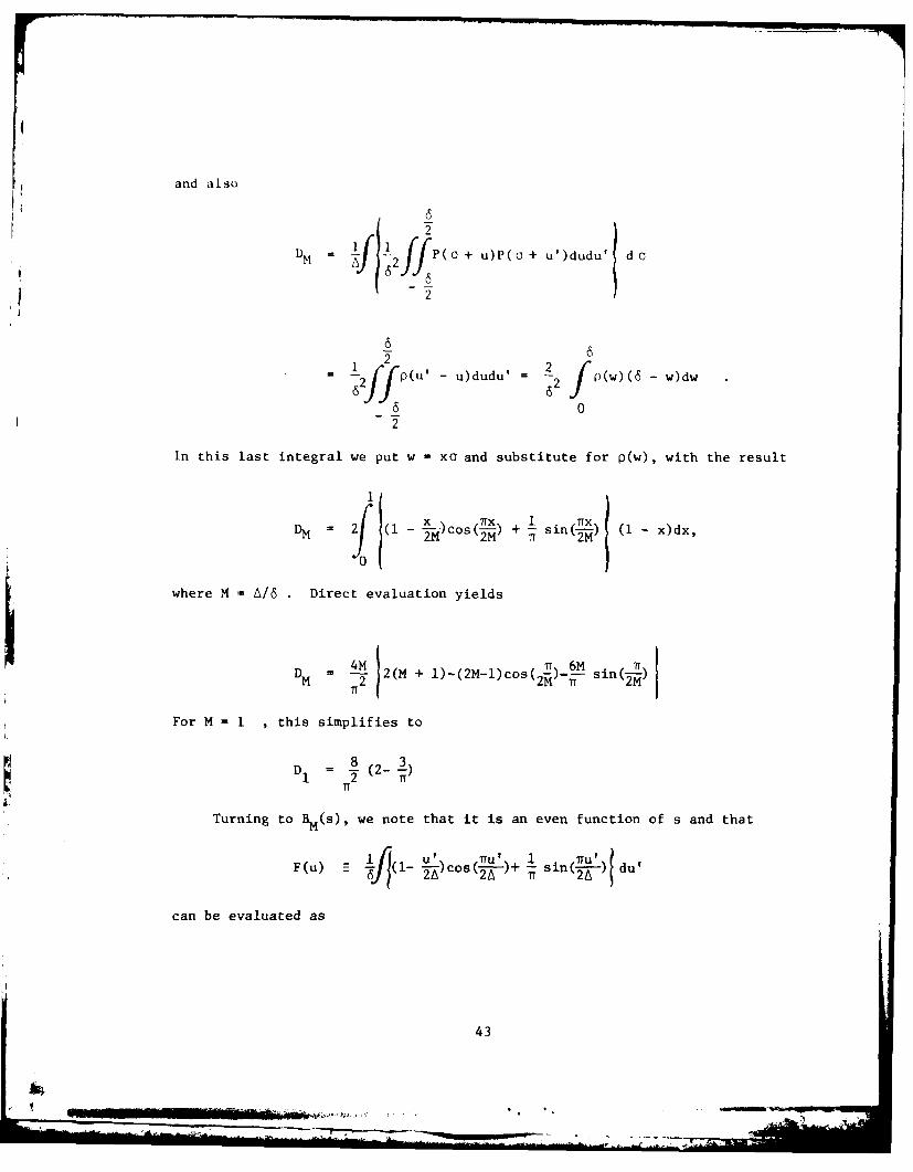
and also
D P(0 + u)P(o + u')dudu' doM 2
1 2 2
fpjj 6 j~uu2 Pw( d
60
In this last integral we put w = xo and substitute for p(w), with the result
xlrx 1 lix
-*)cos(--) + - sin(x-) (1 - x)dx,
where M = A/6 . Direct evaluation yields
DM 4M 2(M + I)-(2M-l)cos( t - Mn - 2
For M = I , this simplifies to
D - (2- 3)
Turning to BM(s), we note that it is an even function of s and that
F(u) csLL . i( )du
can be evaluated as
43
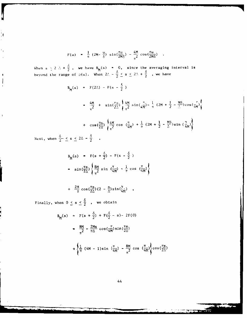
F(u) (2M- u) nU 4M C u
TT sin(j) - 2 c 2s(--)TT
When s > 2 A + , we have BM(s) = 0, since the averaging interval is
beyond the range of o(u). When 2/.- - < s < 2, + - we have• ° 2- - 2
5BM(s) = F(2A) - F(sM
4M 4M T, 1 1 MS
+ + sin(\4 sin(4 ) (2M + )Cos(
(s 14M C 1 2 MS)sin T)
2A 7T 2 1 72 4M
Next, when < s < 2A -2 -2
6 6BM(s) = F(s + .) - F(s
= is ( 8M si 1 iT
sinCS) in (-) ~ cos (7- )
+ 2 cos(I--) (2 s in (I)
6
Finally, when 0 < s < , we obtain
2x
BM(S) - (s + f) + F(- s)- 2F(O)
8M 2Ms ) ins
2 iTA cos(M s 2in()T
+ (4M - l)sin (7-) cos (-) cos(-)
44
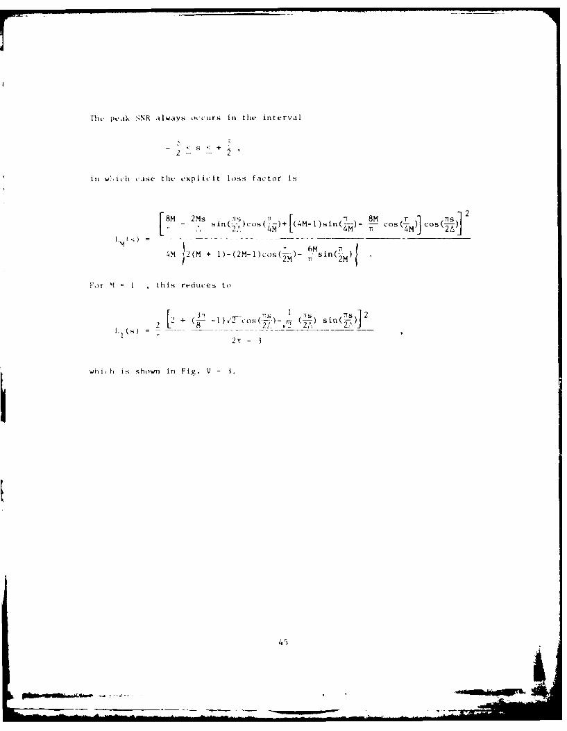
l1h, pe.ik SNR always occurs in the interval
2 - + 1
in W. ih CASe thL expl icit loss factor is
8M 2Ms , TT i 8M cos (M S-7s in( () Cos( (4M)+ (4M-I1) sin (7 Cs(M)0
4M 2(M + I)-(2M-l)cos(-m)- , in (M)
For M = 1 , this reduces to
2 + (- )72 cos( - 7 S sin(7S 2
2~~~ 1T 3__sn~~j2,- I
whi, h is shown in Fig. V- 3.
45

SEUIT L UNC LASSIFIEDS E C RI T C L PN' A T IO N O F T H IS P A G E (W h en D u . Ie ed )
/ . ...... ...... . ......-1R AU RIUCTIONS
REPORT DOCUMENTATION PAGE BEFORE COMPLETING FORM1]-, ----POftA[_ -R -- , ' ] '/ ( 0 GOVT ACCESSION NO. 3. RECIPIENT'S CATALOG NUMBER
TESO R-8J-24VY_ _ _ _ __ _ _ _ _
4. TITLE ,ind Subjslel 5, TYPE OF REPORT & PERIOD COVERED
Sampled-Data Receiver Design and Performance Th l .for BPSK and MSK Spreading Modulations. 6. PERFORMING ORG. REPORT NUMBER
Technical Report 550-1. AUTHOR ,' 8. CONTRACT OR GRANT NUMBERs)
-t hdvard J I Kelly F F 19628-89-C-0002
9. PERFORMING ORGANIZATION NAME AND ADDRESS 10. PROGRAM ELEMENT, PROJECT, TASK
Lincoln Laboratory, M.I.T. AREA & WORK UNIT NUMBERS
P.O..Box 73Lexington, MA 02173
II. CONTR1OLLING OFFICE NAME AND ADDRESS 1 1i1T DATEDepartment of Defense 19 91Janin 8l
[he PentagonWashington, DC 20301 "T NUMBER OF PAGES
54Is. MONITORING AGENCY NAME & ADDRESS (N5dik...4tom C.noin.f'xgfj) 15. SECURITY CLASS. (of ths report)
i..lectronic Systems Division Unclassifiedflanscom AFB / I . 2. "Bedford, MA 01731 1 . 15a. DECLASSIFICATION DOWNGRADING
SCHEDULE
16. DISTRIBUTION STATEMENT (ofthis Report)
Approved for public release; distribution unlimited.
17, DISTRIBUTION STATEMENT (of the abstract entered in Block 20, if differeat from Report)
18. SUPPLEMENTARY NOTES
None
19. KEY ORDS (Conttnue on reverse side if necessary and identify by block number)
spread-spectrum BPSKmatched filter MSK
70. BSTRACT (Continue on reverse side if necessary and identify by block number)
-' Certain spread-spectrum systems make use of waveforms built of basic pulses spread by PN mod-ulation of some kind. In this study the two most common modulation waveforms, BPSK and MSK arediscussed in detail. The objective is to derive receiver structures utilizing sampled-data integrationof the chips, for example, using CCD or digital correlators. A constructive design procedure is de-scribed, together with an analysis of performance in terms of SNR loss due to sampling. It is shownthat sampling loss can be reduced by proper choice of the prefilter which precedes the sampling of thedata.
FOR 1473 EDITION OF I NOV 65 IS OBSOLETE UNCLASSIFIED1D JAN 73 UI_______LASSIFIED_________________
SECURITY CLASSIFICAYION OF THIS PA Data Entered)
or / ~
-. . . _ - . ~ 3~en.j


