
SOUTH
Pole
NORTH
Pole
S N
MAGNET MAGNETIC FIELD

S N
Needle Paper
Copper
Cable
Thumb Nail
MAGNETIC CIRCUIT,
ELECTROMAGNETISM AND
ELECTROMAGNETIC
INDUCTION

The end of lesson, students should be ;
Understand magnetism
Understand the composite series magnetic circuit
Understand the electrical and magnetic quantities
Understand hysteresis
Understand electromagnetism
Determine the magnetic field direction.
Understand electromagnetic induction

iNTRoDUctION
MAGNET is
the material that have two poles NORTH and SOUTH
S N
SOUTH
Pole
NORTH
Pole

iNTRoDUctION
MAGNET can be define as
Material that can attract piece of iron or metal
S N
Needle
Thumb Nail

iNTRoDUctION
MATERIAL that ATTRACTED by the MAGNET is known as
MAGNETIC SUBSTANCES
S
Needle
Thumb Nail
iNTRoDUctION
The ABILITY to ATTRACT the MAGNETIC SUBSTANCES is known as
MAGNETISM
S
Needle
Thumb Nail

iNTRoDUctION
MAGNETIC FIELD is
the force around the MAGNET which can attract any MAGNETIC MATERIAL around it.

FLUX MAGNET is the line around the MAGNET bar which form MAGNETIC FIELD.
S N

TYpEs of MAGNET
There are 2 types of MAGNET
PURE MAGNET
MANUFACTURE MAGNET

PURE MAGNET
Known as MAGNET STONE
The stone ORIGINALY have the
NATURAL MAGNETIC
Basically the stone is found in the form
of IRON ORE

MANUFACTURE
MAGNET
There are 2 types of MANUFACTURE MAGNET
PERMANENT MAGNET
TEMPORARY MAGNET

PERMANENT MAGNET
The ABILITY of the MAGNET to kept its MAGNETISM
The basic shape of PERMANENT MAGNET
U shape horseshoe
ROD Cylinder BAR

PERMANENT MAGNET
U shape Horseshoe Rod
Cylinder
Bar

Permanent magnet can be obtained by:
naturally or magnetic induction
( metal rub against natural
magnet)
placing a magnet into the coil and then supplied with a high
electrical current.
PERMANENT MAGNET
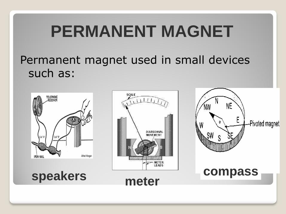
Permanent magnet used in small devices such as:
PERMANENT MAGNET
speakers meter compass

TEMPORARY MAGNET
BECOME MAGNET only when
there is CURRENT SUPPLY to the metal
It has magnetic properties when subjected to magnetic force and it will be lost when power is removed.

TEMPORARY MAGNET
Example :
relay
electric bells

Magnetic flux lines have direction and pole.
The direction of movement outside of the magnetic field lines is from north to south.
CHARACTERISTICS OF MAGNETIC
FORCE LINES (FLUX).
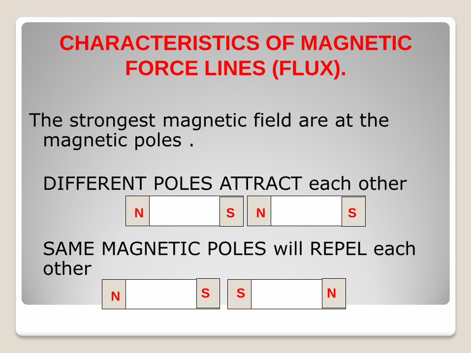
The strongest magnetic field are at the magnetic poles .
DIFFERENT POLES ATTRACT each other SAME MAGNETIC POLES will REPEL each
other
S N S N
S N S N
CHARACTERISTICS OF MAGNETIC
FORCE LINES (FLUX).

FLUX form a complete loop and never intersect with each other.
FLUX will try to form a loop as small as possible.
S N
CHARACTERISTICS OF MAGNETIC
FORCE LINES (FLUX).

MAGNETIC QUANTITY CHARACTERISTICS
Magnetic Flux Magnetic flux is the amount of
magnetic field produced by a magnetic source.
The symbol for magnetic flux is .
The unit for magnetic flux is the
weber, Wb.

MAGNETIC QUANTITY CHARACTERISTICS
Magnet Flux density
The symbol for magnetic flux
density is B.
The unit is tesla, T
the unit for area A is m2 where
1 T = 1 Wb/m.

MAGNETIC QUANTITY CHARACTERISTICS
Magnet Flux density
Magnetic flux density is the amount of flux passing through a defined area that is perpendicular to the direction of flux

MAGNETIC QUANTITY CHARACTERISTICS
Magnetic flux density =
area
flux magnetic
A
ΦB Tesla

MAGNETIC QUANTITY CHARACTERISTICS
Example 3
A magnetic pole face has rectangular section having dimensions 200mm by 100mm. If the total flux emerging from the pole is 150Wb, calculate the flux density.
A
ΦB
Area, A
Flux, Φ
B?

MAGNETIC QUANTITY CHARACTERISTICS
Solution 3 Magnetic flux, = 150 Wb = 150 x 10-6 Wb
Cross sectional area, A = 200mm x 100mm = 20 000 x 10-6 m2
Flux density,
= 7.5 mT
6
6
1020000
10150
A
ΦB

MAGNETOMOTIVE FORCE (MMF) The force which creates the magnetic flux in a
magnetic circuit is called magnetomotive force (mmf)
- The mmf is produced when a current passes through a coil of wire. The mmf is the product of the number of turns(N) and current (I) through the coil.
Unit = Ampere Turns (A.T)
Formula , Fm = N x I
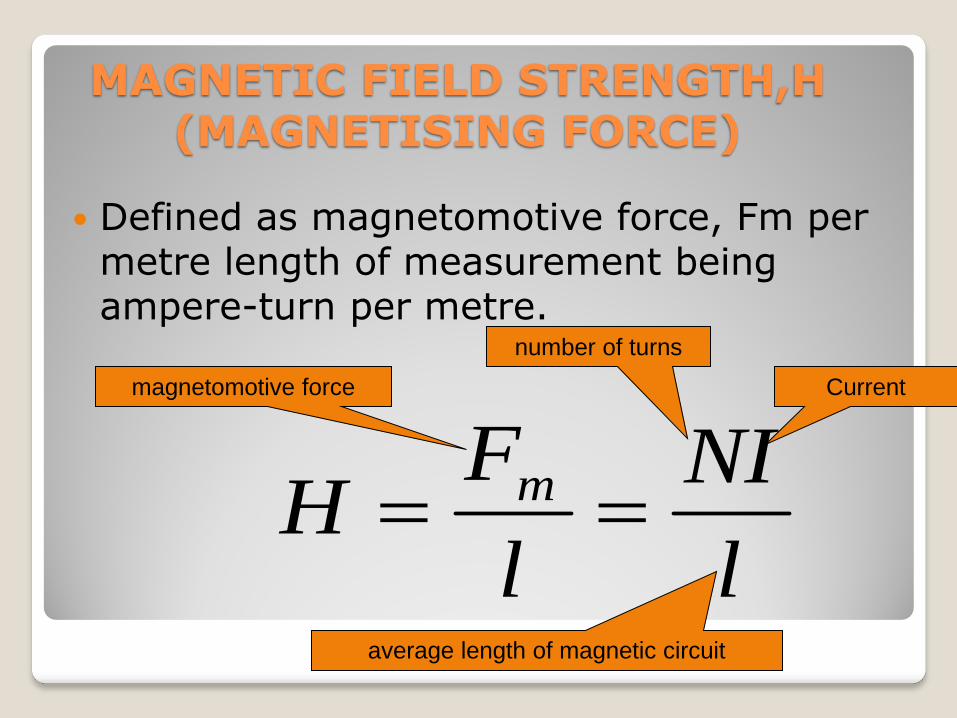
MAGNETIC FIELD STRENGTH,H (MAGNETISING FORCE)
Defined as magnetomotive force, Fm per metre length of measurement being ampere-turn per metre.
Current
l
NI
l
FH m
magnetomotive force
number of turns
average length of magnetic circuit

MAGNETIC FIELD STRENGTH,H (MAGNETISING FORCE)
Example 1
A current of 500mA is passed through a 600 turn coil wound of a toroid of mean diameter 10cm. Calculate the magnetic field strength.
l
NI
l
FH m
Current, I
Turn, N
Diameter, d
H?

MAGNETIC FIELD STRENGTH,H (MAGNETISING FORCE)
Solution 1 I = 0.5A
N = 600
l = x 10 x 10-2m
mATH
H
metreampereturnl
NIH
/81.954
3142.0
5.0600
/

MAGNETIC FIELD STRENGTH,H (MAGNETISING FORCE)
Example 2 An iron ring has a cross-sectional area of 400 mm2. The coil resistance is 474 Ω and the supply voltage is 240 V and a mean diameter of 25 cm. it is wound with 500 turns. Calculate the magnetic field strength, H
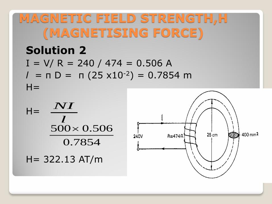
MAGNETIC FIELD STRENGTH,H (MAGNETISING FORCE)
Solution 2 I = V/ R = 240 / 474 = 0.506 A
l = π D = π (25 x10-2) = 0.7854 m
H=
H=
H= 322.13 AT/m
l
NI
7854.0
506.0500

PERMEABILITY
For air, or any other non-magnetic medium, the ratio of magnetic flux density to magnetic field strength is constant ,
This constant is called the permeability of free space and is equal to 4 x 10⁻⁷ H/m.
H
B
µ0

PERMEABILITY
For any other non-magnetic medium, the ratio
For all media other than free space
r
rH
B0

PERMEABILITY
r is the relative permeability and is defined as
r varies with the type of magnetic material.
in vacuumdensity flux
materialin density flux r

PERMEABILITY
r for a vacuum is 1 is called the absolute permeability.
The approximate range of values of
relative permeability r for some common magnetic materials are :
Cast iron r = 100 – 250 Mild steel r = 200 – 800 Cast steel r = 300 – 900

PERMEABILITY
Example 4 A flux density of 1.2 T is produced in a piece of cast steel by a magnetizing force of 1250 A/m. Find the relative permeability of the steel under these conditions.
HB r0
Flux density,
B
H
µr?

PERMEABILITY
Solution 4
HB r0
764
)1250)(104(
2.17
0
H
Br

RELUCTANCE
Reluctance,S is the magnetic resistance of a magnetic circuit to presence of magnetic flux.
Reluctance, The unit for reluctance is 1/H or H-1 or A-T/Wb
AAHBBA
HlFS
r
m
0)/(

RELUCTANCE
Example 5
Determine the reluctance of a piece of metal of length 150mm and cross sectional area is 1800mm2when the relative permeability is 4 000. Find also the absolute permeability of the metal.
S?
Length, l µr µ?

RELUCTANCE
Solution 5 Reluctance, = = 16 579 H-1
Absolute permeability,
=
AS
r0
)101800)(4000)(104(
1015067
3
r 0)4000)(104( 7
= 5.027 x 10⁻³ H/m

ELECTROMAGNET
Is a magnetic iron core produced when the current flowing through the coil.
Thus, the magnetic field can be produced when there is a current flow through a conductor.
The direction of the magnetic field can be determined using the method:
1. Right Hand Grip Rules 2. Maxwell's screw Law. 3. Compass Three rules may be used to indicate the
direction of the current and the flux produced by current carrying conductor.

Right Hand Grip Rule
is a physics principle applied to electric current passing through a solenoid, resulting in a magnetic field.

Right Hand Grip Rule
When you wrap your right hand around the solenoid
your fingers in
the direction of
the conventional
current
your thumb points
in the direction of
the magnetic
north pole

Right Hand Grip Rule It can also be applied to electricity passing through a straight wire
the thumb points in the direction of the conventional current (from +ve to -ve)
the fingers point in the direction of the magnetic lines of flux.

Another way to determine the direction of the flux and current in a conductor is to use Maxwell's screw rule.
MAXWELL’S SCREW LAW

a right-handed screw is turned so that it moves forward in the same direction as the current, its direction of rotation will give the direction of the magnetic field.
MAXWELL’S SCREW
LAW

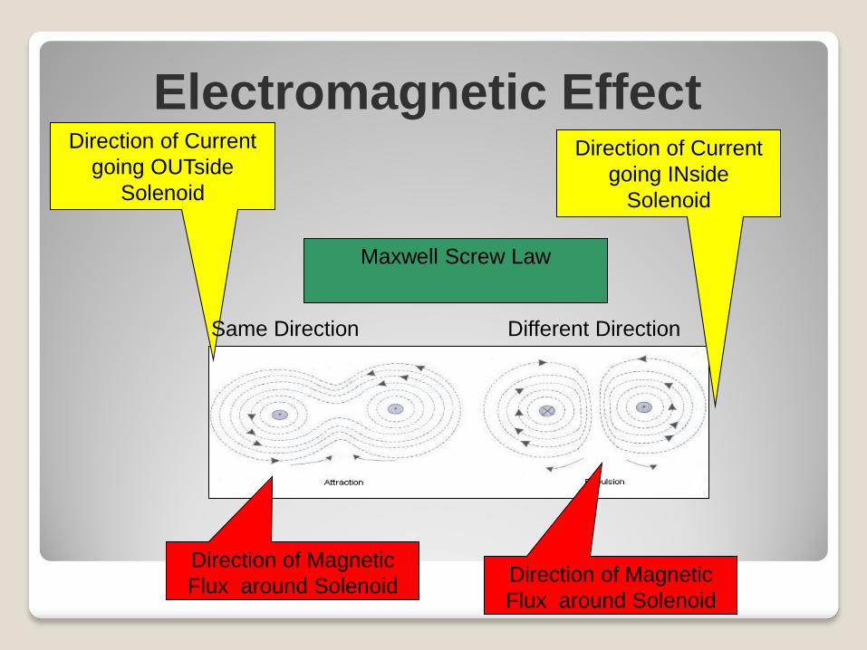
Electromagnetic Effect Direction of Current
going INside
Solenoid
Direction of Magnetic
Flux around Solenoid
Direction of Current
going OUTside
Solenoid
Direction of Magnetic
Flux around Solenoid
Right Hand Grip
Rule
Electromagnetic Effect Direction of Current
going INside
Solenoid
Direction of Magnetic
Flux around Solenoid
Direction of Current
going OUTside
Solenoid
Direction of Magnetic
Flux around Solenoid
Same Direction Different Direction
Maxwell Screw Law

Electromagnetic Effect
Factors that influence the strength of the magnetic field of a solenoid
The number of turns
The value of current flow
Types of conductors to produce coil
The thickness of the conductor

ELECTROMAGNETIC INDUCTION
Definition : When a conductor is moved across a magnetic field so as to cut through the flux, an electromagnetic force (emf) is produced in the conductor.
This effect is known as electromagnetic induction.
The effect of electromagnetic induction will cause induced current.

ELECTROMAGNETIC INDUCTION
2 laws of electromagnetic induction:
i. Faraday’s law
ii.Lenz’z Law

Faraday’s law It is a relative movement of the magnetic
flux and the conductor then causes an emf and thus the current to be induced in the conductor.
Induced emf on the conductor could be produced by 2 methods
flux cuts conductor or
conductor cuts flux.

Faraday’s law
Faraday’s First Law : Flux cuts conductor
When the magnet is moved towards the coil, a deflection is noted on the galvanometer showing that a current has been produced in the coil.

Faraday’s law
Faraday’s Second Law :Conductor cuts flux
When the conductor is moved through a magnetic field . An emf is induced in the conductor and thus a source of emf is created between the ends of the conductor.

Faraday’s law
This induced electromagnetic field is given by E = Blv volts
B =flux density, T l =length of the conductor in the magnetic
field, m v =conductor velocity, m/s
If the conductor moves at the angle to
the magnetic field, then E = Blv sin volts
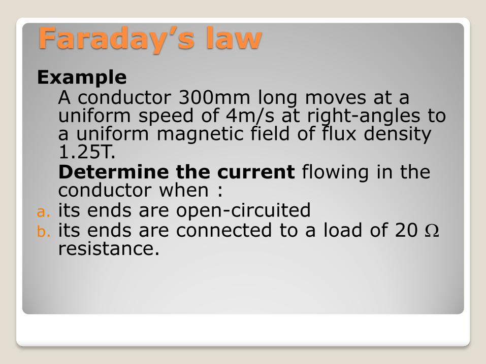
Faraday’s law
Example A conductor 300mm long moves at a
uniform speed of 4m/s at right-angles to a uniform magnetic field of flux density 1.25T.
Determine the current flowing in the conductor when :
a. its ends are open-circuited b. its ends are connected to a load of 20
resistance.

Faraday’s law
Solution a. If the ends of the conductor are open
circuited no current will flow .

Faraday’s law Solution b. E.m.f. can only produce a current if there is a
closed circuit. When a conductor moves in a magnetic field it will have an e.m.f. induced.
Induced e.m.f. , E = Blv =(1.25)(0.3)(4) = 1.5 v From Ohm’s law
mAI
I
R
EI
75
20
5.1

Lenz’z law
The direction of an induced emf is always such that it tends to set up a current opposing the motion or the change of flux responsible for inducing that emf

Formula
AS
r0
l
NI
l
FH m
A
ΦB
MAGNETIC FIELD STRENGTH
RELUCTANCE
MAGNETIC FLUX DENSITY
PERMEABILITY H
Br0
AAHBBA
HlFS
r
m
0)/(
MAGNETOMOTIVE FORCE (MMF), Fm = N x I


Composite magnetic circuit
A series magnetic circuit that has parts of
different dimensions and material is called
composite magnetic circuit.
Each part will have its own reluctance. Total
reluctance is equal to the sum of reluctances
of individual parts.
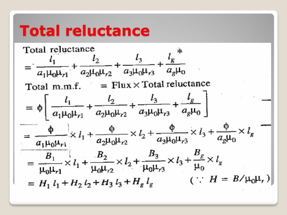
Total reluctance

Comparison between magnetic and electric circuit

Similarities & dissimilarities between magnetic circuit and electric circuit
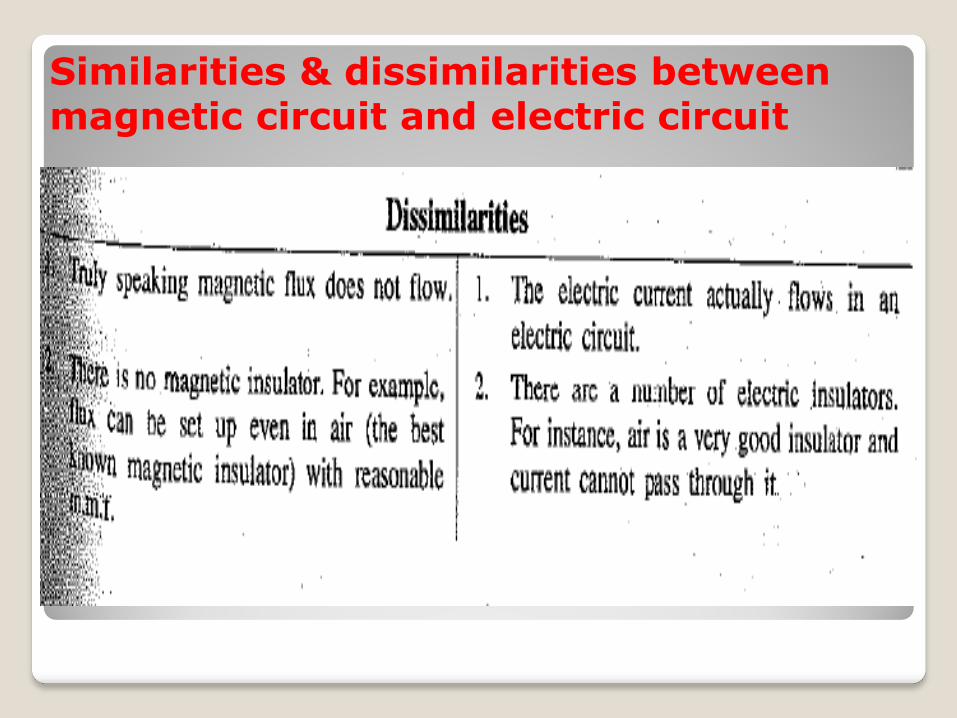
Similarities & dissimilarities between magnetic circuit and electric circuit

Hysterisis and hysterisis loss
Figure 7.6


