Download - USER MANUAL Vacuum Source Connection

USER MANUAL
Vacuum Source
Connection
11-01-18
Revision 5.0
Culturing Cells in a Mechanically Active Environment™ Flexcell® International Corporation 2730 Tucker Street, Suite 200 Burlington, NC 27215
800-728-3714 (919) 732-1591 FAX: (919) 732-5196 www.flexcellint.com
COPYRIGHT © 2009 FLEXCELL INTERNATIONAL CORPORATION

FLEXCELL® INTERNATIONAL CORPORATION
i
TABLE OF CONTENTS
Introduction ............................................................................................................ 1
Vacuum Source Requirements for the Flexcell® Tension System ......................................... 1
Equibiaxial Strain.................................................................................................................... 1
Unconstrained Distension ....................................................................................................... 1
Uniaxial Strain ........................................................................................................................ 1
House Vacuum Systems ......................................................................................................... 2
Pressure Reservoir .................................................................................................................. 2
Pressure Reservoir Features / Benefits ............................................................................. 3
Connecting Vacuum Systems to the Flexcell® Tension System ......................... 3
General Information ................................................................................................................ 3
Setting up the Leybold D8B Vacuum Pump........................................................................... 4
Remove Protective Shipping Covers ................................................................................ 4
Connect the Smoke Eliminator Exhaust Filter.................................................................. 4
Connecting the Leybold D8B Vacuum Pump and Pressure Reservoir .................................. 5
Connect the Pressure Reservoir to the Vacuum Pump ..................................................... 5
Connect the Pressure Reservoir to the FlexLink®............................................................. 5
Final Assembly of Vacuum Pump and Pressure Reservoir .............................................. 6
Connecting the Leybold D8B Vacuum Pump without the Pressure Reservoir ...................... 7
Connecting a House Vacuum System and the Pressure Reservoir ......................................... 8
Connecting a House Vacuum System without the Pressure Reservoir................................... 9
Physical Specifications ........................................................................................... 9
FLEXCELL® INTERNATIONAL CORPORATION
1
INTRODUCTION
VACUUM SOURCE REQUIREMENTS FOR
THE FLEXCELL® TENSION SYSTEM
Optimizing performance on the Tension
System requires a vacuum source with
predetermined minimum specifications. The
system can be used with the following
configurations:
• Equibiaxial strain (with cylindrical
Loading Stations™),
• Unconstrained distension (without
Loading Stations™),
• Uniaxial strain (with Arctangle®
Loading Stations™).
Each configuration has different vacuum
requirements. These requirements do not
demand the purchase of two pumps, but
determine the minimum pump specifications
that the user will need to use the Tension
System with their chosen configuration.
EQUIBIAXIAL STRAIN
The equibiaxial strain configuration uses the
BioFlex® plate with the cylindrical Loading
Stations™ such that the membrane deforms
over the top planar surface of the Loading
Station™ (loading posts). Distension of the
membrane in this way results in equibiaxial
strain on the area of the membrane over the
Loading Station™. The vacuum requirement
to produce a maximum strain of 22% on the
BioFlex® membrane in this configuration is
-90 kPa. To operate the Tension System in
this configuration, a pump is required that
will provide the following minimum
specifications:
Maximum Vacuum: -100 kPa
Minimum Free Airflow Rate: 5.7 cfm (161
L/min)
Flexcell® recommends the Leybold D8B Oil-
Sealed Rotary Vane Vacuum Pump with the
ARP 4-8 Oil Return accessory. This pump is
used to calibrate the Tension System for both
the equibiaxial and unconstrained
configurations. It is highly recommended for
strong performance and durability. This
vacuum pump can be purchased directly from
Flexcell®.
UNCONSTRAINED DISTENSION
The unconstrained distension configuration
uses the BioFlex® plate without the Loading
Stations™ such that the BioFlex® membrane
deforms freely downward. Distension of the
membrane in this way results in a non-
uniform strain profile on the membrane. The
vacuum requirement to produce a maximum
strain of 30% on the BioFlex® membrane in
this configuration is only -30 kPa. To operate
the Tension System in this configuration, a
vacuum pump is required that will provide
the following minimum specifications:
Maximum Vacuum: -50 kPa
Minimum Free Airflow Rate: 1.3 cfm (37
L/min)
UNIAXIAL STRAIN
The uniaxial strain configuration uses the
UniFlex® plate, the linear Tissue Train® plate
or the trapezoidal Tissue Train® plate with
the Arctangle® Loading Stations™ such that
the membrane deforms over the top planar
surface of the Loading Station™ (loading
posts) only at the east and west poles.
Distension of the membrane in this way
results in uniaxial strain on the area of the
membrane over the Loading Station™. The
vacuum requirement to produce a maximum
strain of 12% on the UniFlex® membrane in

FLEXCELL® INTERNATIONAL CORPORATION
2
this configuration is -90 kPa. The vacuum
requirement to produce a maximum strain of
20% on the either Tissue Train® membrane in
this configuration is -90 kPa. To operate the
Tension System in this configuration, a pump
is required that will provide the following
minimum specifications:
Maximum Vacuum: -100 kPa
Minimum Free Airflow Rate: 5.7 cfm (161
L/min)
Again, Flexcell® recommends the Leybold
D8B Oil-Sealed Rotary Vane Vacuum Pump
with the ARP 4-8 Oil Return accessory. This
pump is used to calibrate the Tension System
for both uniaxial configuration.
HOUSE VACUUM SYSTEMS
If a house vacuum system is being used in the
laboratory, the system capabilities must be
known to determine if it is sufficient to
operate the Tension system in the desired
configuration. Finding the maximum vacuum
level of the vacuum system should not be a
problem. The free airflow rate of the pump
used for house vacuum will likely be greater
than that required by the system. However,
because house vacuum systems are often
shared, neither the airflow rate nor maximum
vacuum level available are certain to be
stable at all times.
If access of equipment to measure the
capabilities of the house vacuum system is
limited, the Tension system can be safely
tested by connecting it directly to the house
vacuum system. The performance of the unit
can be noted with respect to the house
vacuum system to determine if it will be
effective enough for experimental purposes.
The house vacuum system can be tested by
programming a regimen with the following
parameters: Sine wave, 0-20% elongation,
1.0 Hz, DC% = 50, 1000 cycles.
This regimen should be run with standard
FLEX IN and FLEX OUT tubing lengths and
a BioFlex® baseplate with four culture plates
in place and four 25 mm cylindrical Loading
Stations™. If the actual output maximum %
elongation is 14% or higher, then the house
vacuum system is providing enough vacuum
to run the unit at its maximum capability. If
the output maximum % elongation is lower
than 14%, then the house vacuum system is
going to be a limitation in the performance of
the system. This will only be a problem if the
% elongation and frequency combination that
are desired for particular experiments is
unachievable. Using the Tension system with
a vacuum system that does not allow it to run
at its maximum capability will not damage
the unit. The Tension system will adjust to
make the best possible use of the vacuum
system that is being used.
If there are questions about the operation of
the Tension System with the house vacuum
system, call Flexcell® and ask to speak with a
technical service representative.
PRESSURE RESERVOIR
The Flexcell Pressure Reservoir (Fig. 1)
enhances the performance of the Tension
System. The Pressure Reservoir serves two
primary roles: 1) a system-matched
volumetric storage device, and 2) a
pneumatic pulse dampener or “shock
absorber”. Whether this device is used in
conjunction with a house vacuum source or
with a stand-alone vacuum pump, the system
performance is enhanced by the addition of
the Pressure Reservoir.

FLEXCELL® INTERNATIONAL CORPORATION
3
Figure 1. Pressure Reservoir.
Pressure Reservoir Features & Benefits
• Suitable with either vacuum or positive
pressure sources.
• Isolates or buffers research equipment
from transient spikes or surges from
vacuum or positive pressure sources.
• Dampens the pressure demand
fluctuations seen by the vacuum pump or
positive pressure source.
• Provides high volume capacity important
for rigorous testing regimens.
• Stabilizes the Flexcell® Tension System
performance while operating multiple
baseplates.
• Constructed from highest quality
components including ASME approved
vessel for durable service.
• Includes a large, 3 ½” diameter easy to
read compound gauge to monitor the
system source pressure as seen by either
the vacuum or positive pressure source.
• Quick disconnect fittings included to
adapt to your Flexcell® Tension System.
• Interface to pressure or vacuum source is
accomplished via a 5 foot length of ½” ID
wire reinforced clear tubing.
• Large 7.5 gal (28.4 liter) capacity in
compact design.
• Onboard valve to seal reservoir from
equipment.
• Equipped with handle and wheels for
portability.
CONNECTING VACUUM SYSTEMS TO THE FLEXCELL® TENSION SYSTEM
GENERAL INFORMATION
The Flexcell® Tension System has a single
connection for the vacuum source. This
connection port is located on the back of the
FlexLink® and is labeled SYSTEM as shown
in Figure 2.
All of the following vacuum source
configurations will need a single source line
coming from the pressure reservoir, or
directly from the vacuum source, to the
SYSTEM port on the back of the FlexLink®.
The SYSTEM port requires tubing
dimensions of 3/8” (9.5 mm) outer diameter
by ¼” (6.4 mm) inner diameter. Flexcell®
recommends the green vacuum tubing that is
provided with the Tension System. If you do
not use the pressure reservoir or pump
recommended by Flexcell®, this tubing or
other rigid-walled tubing with the same
dimensions must be adapted to your vacuum
source.

FLEXCELL® INTERNATIONAL CORPORATION
4
Figure 2A. Vacuum source tubing connected to an FX-6000TM Tension FlexLink®.
Figure 2B. Vacuum source tubing connected to a Flex Jr.TM Tension FlexLink®.
SETTING UP THE LEYBOLD D8B VACUUM PUMP
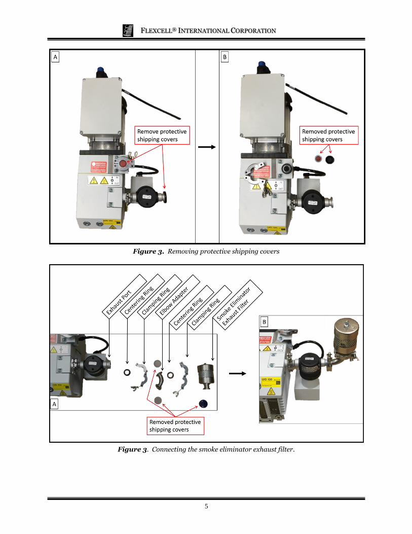
REMOVE PROTECTIVE SHIPPING
COVERS
Remove the Leybold D8B Vacuum Pump
from its box and set on a flat surface for
assembly. Remove the orange and black
protective covers from the vacuum pump
inlet and exhaust ports as shown in Figure 3.
To remove the orange cover, unscrew the
wingnut clamping ring until the ring can be
opened. Leave the rubber centering ring with
mesh in place.
CONNECT THE SMOKE ELIMINATOR
EXHAUST FILTER
Take out the fittings and parts shown below
in Figure 4A to attach the smoke eliminator
exhaust filter. Remove the protective
shipping covers from the elbow adapter and
smoke eliminator exhaust filter. Connect the
elbow adapter to the exhaust port using a
centering ring and a clamping ring. The
centering ring should be inserted to fit
between the flanges of the exhaust port and
the elbow adapter. The clamping ring is
secured around the flanges and centering
ring, then tightened with the wingnut. Install
the elbow such that the open end is facing
upwards. Use the same technique to connect
the smoke eliminator exhaust filter to the
elbow adapter using a centering ring and a
clamping ring. The assembled smoke
eliminator exhaust filter should appear as
shown in Figure 4B.
FLEXCELL® INTERNATIONAL CORPORATION
5
Figure 3. Removing protective shipping covers
Figure 3. Connecting the smoke eliminator exhaust filter.
FLEXCELL® INTERNATIONAL CORPORATION
6
CONNECTING THE LEYBOLD D8B VACUUM PUMP AND PRESSURE
RESERVOIR
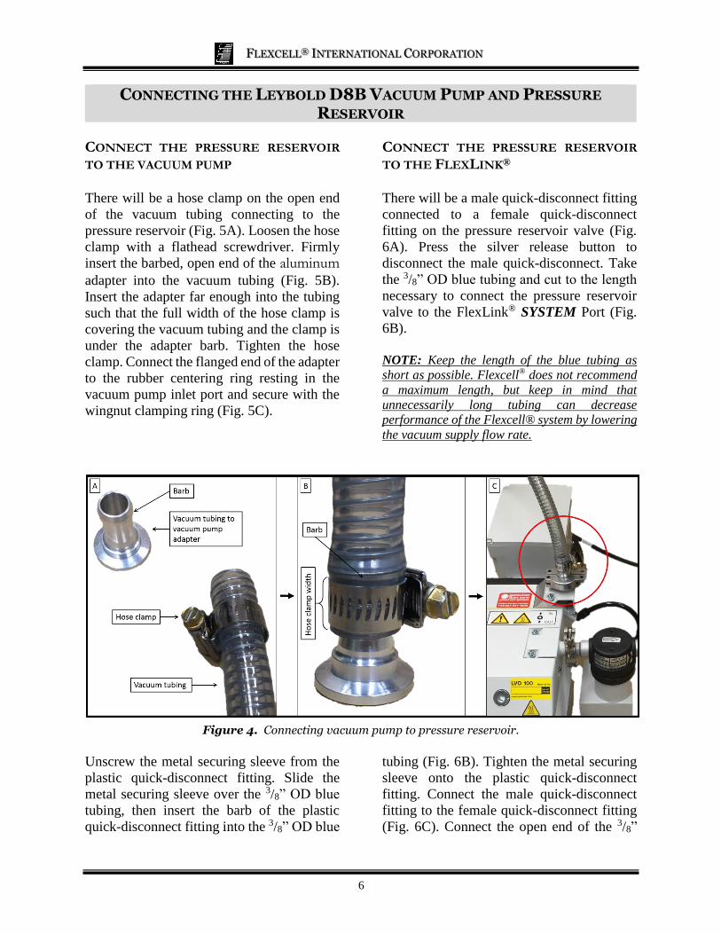
CONNECT THE PRESSURE RESERVOIR
TO THE VACUUM PUMP
There will be a hose clamp on the open end
of the vacuum tubing connecting to the
pressure reservoir (Fig. 5A). Loosen the hose
clamp with a flathead screwdriver. Firmly
insert the barbed, open end of the aluminum
adapter into the vacuum tubing (Fig. 5B).
Insert the adapter far enough into the tubing
such that the full width of the hose clamp is
covering the vacuum tubing and the clamp is
under the adapter barb. Tighten the hose
clamp. Connect the flanged end of the adapter
to the rubber centering ring resting in the
vacuum pump inlet port and secure with the
wingnut clamping ring (Fig. 5C).
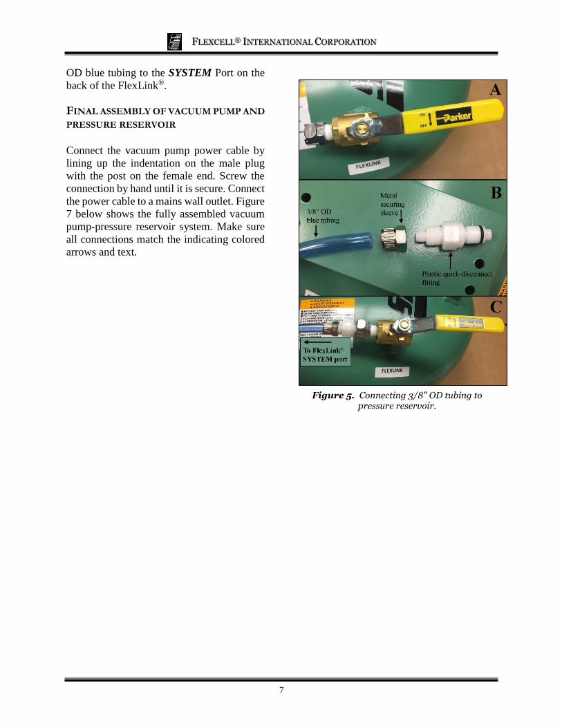
CONNECT THE PRESSURE RESERVOIR
TO THE FLEXLINK®
There will be a male quick-disconnect fitting
connected to a female quick-disconnect
fitting on the pressure reservoir valve (Fig.
6A). Press the silver release button to
disconnect the male quick-disconnect. Take
the 3/8” OD blue tubing and cut to the length
necessary to connect the pressure reservoir
valve to the FlexLink® SYSTEM Port (Fig.
6B).
NOTE: Keep the length of the blue tubing as
short as possible. Flexcell® does not recommend
a maximum length, but keep in mind that
unnecessarily long tubing can decrease
performance of the Flexcell® system by lowering
the vacuum supply flow rate.
Figure 4. Connecting vacuum pump to pressure reservoir.
Unscrew the metal securing sleeve from the
plastic quick-disconnect fitting. Slide the
metal securing sleeve over the 3/8” OD blue
tubing, then insert the barb of the plastic
quick-disconnect fitting into the 3/8” OD blue
tubing (Fig. 6B). Tighten the metal securing
sleeve onto the plastic quick-disconnect
fitting. Connect the male quick-disconnect
fitting to the female quick-disconnect fitting
(Fig. 6C). Connect the open end of the 3/8”
FLEXCELL® INTERNATIONAL CORPORATION
7
OD blue tubing to the SYSTEM Port on the
back of the FlexLink®.
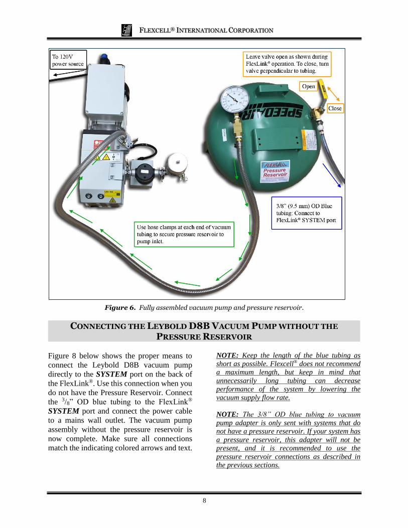
FINAL ASSEMBLY OF VACUUM PUMP AND
PRESSURE RESERVOIR
Connect the vacuum pump power cable by
lining up the indentation on the male plug
with the post on the female end. Screw the
connection by hand until it is secure. Connect
the power cable to a mains wall outlet. Figure
7 below shows the fully assembled vacuum
pump-pressure reservoir system. Make sure
all connections match the indicating colored
arrows and text.
Figure 5. Connecting 3/8" OD tubing to pressure reservoir.
FLEXCELL® INTERNATIONAL CORPORATION
8
Figure 6. Fully assembled vacuum pump and pressure reservoir.
CONNECTING THE LEYBOLD D8B VACUUM PUMP WITHOUT THE
PRESSURE RESERVOIR
Figure 8 below shows the proper means to
connect the Leybold D8B vacuum pump
directly to the SYSTEM port on the back of
the FlexLink®. Use this connection when you
do not have the Pressure Reservoir. Connect
the 3/8” OD blue tubing to the FlexLink®
SYSTEM port and connect the power cable
to a mains wall outlet. The vacuum pump
assembly without the pressure reservoir is
now complete. Make sure all connections
match the indicating colored arrows and text.
NOTE: Keep the length of the blue tubing as
short as possible. Flexcell® does not recommend
a maximum length, but keep in mind that
unnecessarily long tubing can decrease
performance of the system by lowering the
vacuum supply flow rate.
NOTE: The 3/8” OD blue tubing to vacuum
pump adapter is only sent with systems that do
not have a pressure reservoir. If your system has
a pressure reservoir, this adapter will not be
present, and it is recommended to use the
pressure reservoir connections as described in
the previous sections.

FLEXCELL® INTERNATIONAL CORPORATION
9
Figure 7. Connecting vacuum pump without pressure reservoir.
CONNECTING A HOUSE VACUUM SYSTEM AND THE PRESSURE
RESERVOIR
Figure 9 below shows the proper means to connect a house vacuum system to the pressure reservoir
and FlexLink®. Use this connection when you have a house vacuum system and a pressure
reservoir. Make all connections as indicated by the colored arrows and text.
NOTE: Keep the length of the blue tubing as short as possible. Flexcell® does not recommend a maximum
length, but keep in mind that unnecessarily long tubing can decrease performance of the system by lowering
the vacuum supply flow rate.
NOTE: The outlet on your house vacuum system may need to be adapted to fit the reinforced vacuum
supply tubing shown in Figure 9.
Figure 9. Connecting the Pressure Reservoir to a house vacuum supply.

FLEXCELL® INTERNATIONAL CORPORATION
10
CONNECTING A HOUSE VACUUM SYSTEM WITHOUT THE PRESSURE
RESERVOIR
To connect a house vacuum system directly
to the FlexLink®, you will need to adapt the
outlet on your house vacuum to fit the 3/8”
(9.5mm) OD blue vacuum tubing supplied
with the Tension System. The blue vacuum
tubing should be connected directly from the
house vacuum source to the SYSTEM port on
the back of the FlexLink®.
NOTE: Keep the length of the blue tubing as
short as possible. Flexcell® does not recommend
a maximum length, but keep in mind that
unnecessarily long tubing can decrease
performance of the system by lowering the
vacuum supply flow rate.
PHYSICAL SPECIFICATIONS
Oerlikon D8B Vacuum Pump w/ ARP 4-8 Oil Return
(Item# LBV-4000): Size (unit only), L x W x H: 19 ½” x 10 ¾” x 10” (49.5 x 27.3 x 25.4 cm) Power Requirements: 115 volts, 60 Hz
Weight (unit only): 55.8 lbs (25.3 kg)
Oerlikon D8B Vacuum Pump w/ ARP 4-8 Oil Return, Power Cable, and Smoke Eliminator
Size L x W x H: 21 ½” x 14 ½” x 13 7/8” (54.6 x 36.8 x 35.2 cm) Power Requirements: 115 volts, 60 Hz
Weight (unit only): 57.6 lbs (26.1 kg)
Pressure Reservoir
(Item# PR-4000): Size (unit only), L x W x H: 16 3/16” x 16 3/16” x 9 3/8” (41.1 x 41.1 x 23.8 cm)
Power Requirements: N/A
Weight (unit only): 26.5 lbs (12.0 kg)


