Download - Validation Master Plan
PharmaceuticalMaster Validation PlanThe Ultimate Guide toFDA, GMP, and GLP Compliance

SL3305_ FM_fm Page ii Thursday, November 8, 2001 3:07 PM
ST. LUCIE PRESSA CRC Press Company
Boca Raton London New York Washington, D.C.
PharmaceuticalMaster Validation PlanThe Ultimate Guide toFDA, GMP, and GLP Compliance
Syed Imtiaz Haider, Ph.D.
Every effort has been made to ensure that the contents of this generic validation master planare accurate and that recommendations are appropriate and made in good faith. The authoraccepts no responsibility for inaccuracies or actions taken by companies subsequent to theserecommendations.
This book contains information obtained from authentic and highly regarded sources. Reprinted materialis quoted with permission, and sources are indicated. A wide variety of references are listed. Reasonableefforts have been made to publish reliable data and information, but the authors and the publisher cannotassume responsibility for the validity of all materials or for the consequences of their use.
Neither this book nor any part may be reproduced or transmitted in any form or by any means, electronicor mechanical, including photocopying, microfilming, and recording, or by any information storage orretrieval system, without prior permission in writing from the publisher.
The consent of CRC Press LLC does not extend to copying for general distribution, for promotion, forcreating new works, or for resale. Specific permission must be obtained in writing from CRC Press LLCfor such copying.
Direct all inquiries to CRC Press LLC, 2000 N.W. Corporate Blvd., Boca Raton, Florida 33431.
Trademark Notice:
Product or corporate names may be trademarks or registered trademarks, and areused only for identification and explanation, without intent to infringe.
Visit the CRC Press Web site at www.crcpress.com
© 2002 by CRC Press LLC St. Lucie Press is an imprint of CRC Press LLC
No claim to original U.S. Government worksInternational Standard Book Number 1-57444-330-5
Library of Congress Card Number 2001048618Printed in the United States of America 1 2 3 4 5 6 7 8 9 0
Printed on acid-free paper
Library of Congress Cataloging-in-Publication Data
Haider, Syed Imtiaz.Pharmaceutical master validation plan : the ultimate guide to FDA, GMP, and GLP
compliance / by Syed Imtiaz Haider.p. cm.
Includes bibliographical references and index.ISBN 1-57444-330-5 (alk. paper)1. Pharmaceutical technology—Quality control. 2. Pharmaceutical industry—Quality
control. I. Title.[DNLM: 1. Drug Industry—standards. 2. Drug and Narcotic Control. 3. Facility
Regulation and Control. 4. Guideline Adherence—organization & administration. 5.Quality Control. 6. Technology, Pharmaceutical—standards. QV 736 H149p 2001]RS192 .H3533 2001615'.19'021873—dc21 2001048618
SL3305_ FM_fm Page iv Thursday, November 8, 2001 3:07 PM
LIMITED WARRANTY
CRC Press LLC warrants the physical disk(s) enclosed herein to be free of defects in materials andworkmanship for a period of thirty days from the date of purchase. If within the warranty periodCRC Press LLC receives written notification of defects in materials or workmanship, and suchnotification is determined by CRC Press LLC to be correct, CRC Press LLC will replace the defectivedisk(s).
The entire and exclusive liability and remedy for breach of this Limited Warranty shall be limitedto replacement of defective disk(s) and shall not include or extend to any claim for or right to coverany other damages, including but not limited to, loss of profit, data, or use of the software, or special,incidental, or consequential damages or other similar claims, even if CRC Press LLC has beenspecifically advised of the possibility of such damages. In no event will the liability of CRC PressLLC for any damages to you or any other person ever exceed the lower suggested list price or actualprice paid for the software, regardless of any form of the claim.
CRC Press LLC specifically disclaims all other warranties, express or implied, including but notlimited to, any implied warranty of merchantability or fitness for a particular purpose. Specifically,CRC Press LLC makes no representation or warranty that the software is fit for any particular purposeand any implied warranty of merchantability is limited to the thirty-day duration of the LimitedWarranty covering the physical disk(s) only (and not the software) and is otherwise expressly andspecifically disclaimed.
Since some states do not allow the exclusion of incidental or consequential damages, or thelimitation on how long an implied warranty lasts, some of the above may not apply to you.
DISCLAIMER OF WARRANTY AND LIMITS OF LIABILITY
The author(s) of this book have used their best efforts in preparing this material. These efforts includethe development, research, and testing of the theories and programs to determine their effectiveness.Neither the author(s) nor the publisher make warranties of any kind, express or implied, with regardto these programs or the documentation contained in this book, including without limitation warrantiesof merchantability or fitness for a particular purpose. No liability is accepted in any event for anydamages, including incidental or consequential damages, lost profits, costs of lost data or programmaterial, or otherwise in connection with or arising out of the furnishing, performance, or use of theprograms in this book.
SL3305_ FM_fm Page v Thursday, November 8, 2001 3:07 PM
vi
DEDICATION
This book is dedicated to the loving memory of my mother, Khursheedun-nissa, whose encouragement and love have added
substantial value to my career.
SL3305_ FM_fm Page vi Thursday, November 8, 2001 3:07 PM
vii
PREFACE
The regulatory guidelines such as those of the FDA, Current Good Man-ufacturing Practices (cGMP) for Pharmaceuticals, and Good LaboratoryPractices (GLP) require comprehensively documented systems. The guide-lines mentioned above provide only a set of rules to be followed andleave the specificity of the working documents to the individual companies.
The purpose of this book is to provide a generic format for a MasterValidation Plan, also often called a Validation Master Plan (VMP), using apharmaceutical manufacturing site with both sterile and non-sterile oper-ations as the case facility. The intent is to show basic format and samplesof contents for all the sections of the plan, because it provides a roadmap for validation to establish FDA requirements master validation pro-cedures, validation programmes, execution protocols, and resources plan-ning and scheduling.
The pharmaceutical, medical device, and biotech industries are regu-lated worldwide to be in compliance with cGMP and GLP principles. Eachcompany is required to create a VMP to qualify its equipment, utilities,buildings, and personnel. The template VMP available enables the endusers to understand the principles and elements of a VMP and providesdocumentation language that is generic to very specific depending on thedepth of the requirements.
Compliance with FDA regulations by the health care industry over thepast decade has been a major goal, especially for those companiesintending to export their product to the U.S. market. As a result, the FDAinspects nearly 300 companies throughout the world every year for cGMPand GLP compliance, but only five or six are able to seek approval forexportation. One reason for this is the absence or inadequacy of a VMP.The key benefits of a VMP include, but are not limited to:
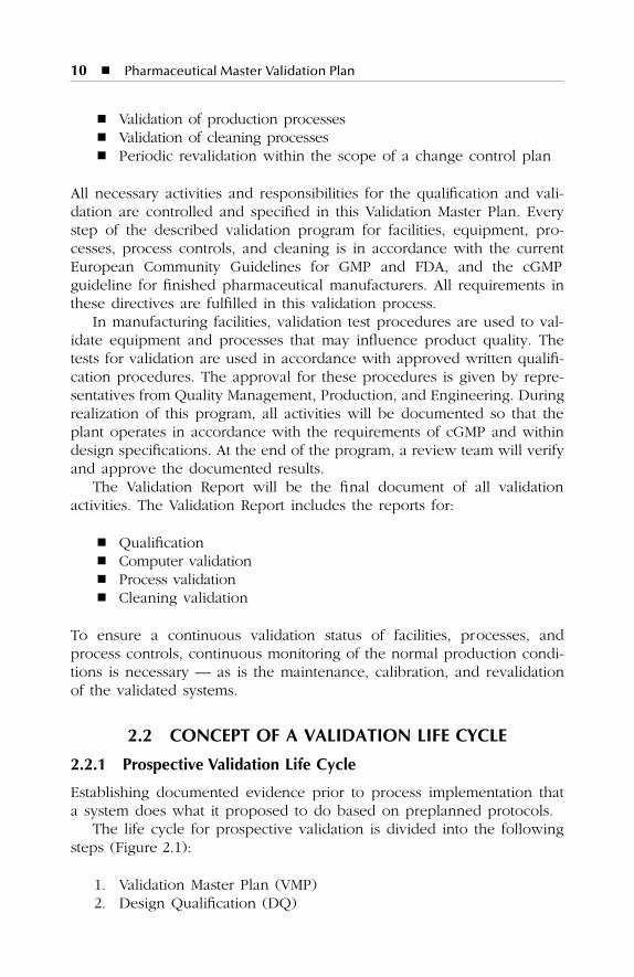
�
Minimize noncompliance
�
Reduce reworks
SL3305_ FM_fm Page vii Thursday, November 8, 2001 3:07 PM
viii
�
Pharmaceutical Master Validation Plan
�
Reduce rejected lots
�
Avoid recalled lots
�
Helps in new drug approval
�
Satisfactory inspections
�
Corporate image
�
Financial gain
�
Secure third-party contracts
�
Corporate legal protection
�
Utility cost reduction
�
Minimize capital expenditures
�
Fewer complaints
�
Reduced testing
�
Improved employee awareness
The Validation Master Plan on CD-ROM is a valuable tool for thosecompanies that are in a process of developing or revising a VMP to achieveFDA, GMP, and GLP compliance. The documentation package is especiallyrelevant to quality assurance (QA) personnel, engineers, utilities engineers,computer engineers, validation designers, internal and external auditors,and to anyone interested in developing a qualification documentationmatrix. The VMP provides administrative solutions for management, bothin text and software.
The author believes that following the broadly based example of aValidation Master Plan, both new and experienced companies can benefitand enhance their existing documentation of a Validation Master Plan tomeet FDA and other regulatory requirements worldwide.
Syed Imtiaz Haider, Ph.D.
September 2001
SL3305_ FM_fm Page viii Thursday, November 8, 2001 3:07 PM
ix
ACKNOWLEDGMENTS
I would like to thank friends and colleagues, especially Javed Zamir,for their help and encouragement in this endeavor and for creating theprofessional environment that demanded that this book be developed.I would like to thank the staff of CRC Press, particularly Drew Giermanand Gail Renard for their patience and diligence in the production ofthis work.
SL3305_ FM_fm Page ix Thursday, November 8, 2001 3:07 PM

SL3305_ FM_fm Page x Thursday, November 8, 2001 3:07 PM
xi
ABOUT THE AUTHOR
Syed Imtiaz Haider
has a Ph.D. in chemistry and is a quality assurancespecialist with more than 12 years of experience in pharmaceutical vali-dation, in-process control, and auditing. He has more than 40 researchpublications in international refereed journals dealing with compounds ofpharmaceutical interest, their isolation, purification, and structure devel-opment. Dr. Haider is a professional consultant, technical writer, andauthor of more than 2000 Standard Operating Procedures based on FDAregulations, ISO 9001, and ISO 14000; a Standard Certified Lead Auditorof IRCA; and registered provisional auditor of EARA. He has written morethan ten manuals for multidisciplinary industries. Dr. Haider has also written
ISO 9001:2000 Document Development Compliance Manual: A CompleteGuide
and CD-ROM, published by CRC Press, Boca Raton, FL, and holdsa copyright certificate of registration on an electronic documentation pack-age on ISO 14001 from the Canadian Intellectual Property Office.
SL3305_ FM_fm Page xi Thursday, November 8, 2001 3:07 PM

SL3305_ FM_fm Page xii Thursday, November 8, 2001 3:07 PM

xiii
PROLOGUE
The purpose of this book is to provide a generic template for a ValidationMaster Plan (VMP), using a broadly based pharmaceutical facility as anexample. The contents of the VMP are based on a hypothetical, newlyconstructed ABC Pharmaceutical facility. The facility is comprised of threebuildings: A, B, and C.
�
Building A is dedicated to the manufacture of dry oral products.
�
Building B is designed to manufacture liquid and semisolid oralproducts.
�
Building C is constructed to manufacture injectables in ampoules,vials, and disposable ready-to-use syringes, and lyophilized prod-ucts in vials.
The information provided in this introduction is intended to help thosewho use this book and its CD-ROM understand the basic elements of aVMP; download the electronic files provided on the CD-ROM on a personalcomputer; and execute the desired changes or directly adopt the contentsfor the development of a VMP in accordance with the operational require-ments of their companies.
VALIDATION MASTER PLAN
What is a Validation Master Plan? There is no official definition; however,based on the interpretation of FDA regulatory guidelines on current GoodManufacturing Practice (cGMP), Good Laboratory Practice, and processvalidation, a suitable definition may be described as:
SL3305_ FM_fm Page xiii Thursday, November 8, 2001 3:07 PM
xiv
�
Pharmaceutical Master Validation Plan
A comprehensive document describing the applicable validationrequirements for a given facility, and providing a plan for meetingthose requirements. The VMP provides a “road map” for validation,to establish a sequence of events followed by facilities audits andinspections.
The benefits of a VMP are not limited to proactive regulatory compli-ance but help in the prevention of omissions and inappropriate or labo-rious testing, scheduling and tracking of tasks, identification of personnelqualifications, and human resource optimization. The overall programgains regulatory and management credibility and helps to avoid unforeseendelays in facility start-up operations for commercial production. The keybenefits involved are:
�
Minimize noncompliance costs
�
Reduce rework
�
Reduce rejected lots
�
Avoid recalled lots
�
Helps in new drug approval
�
Satisfactory inspections
�
Corporate image
�
Financial gain
�
Secure third-party contracts
�
Corporate legal protection
The observations made during the execution of the VMP providestrength to significantly reduce the regulatory risks related to the systemsand initiation of the proactive corrective actions required. The plan pro-vides visibility for the completion of individual tasks and assures systemevaluation, process validation, equipment validation, facility and utilitiesqualification, documentation, environmental control, and monitoring;implementation and execution of the VMP assures process reproducibilitycontrol over the applicable changes and modifications as a result infacilities, equipment, personnel, and materials.
WRITING A VALIDATION MASTER PLAN
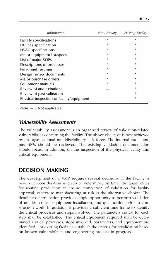
The VMP can be written for a new or existing facility. The followingunique information should be established as a minimal requirement.
For a new facility, this information is readily available and the scopeof the work is easily defined. However, an existing facility may have tobe assessed for vulnerability prior to planning.
SL3305_ FM_fm Page xiv Thursday, November 8, 2001 3:07 PM
�
xv
Vulnerability Assessments
The vulnerability assessment is an organized review of validation-relatedvulnerabilities concerning the facility. The above objective is best achievedby an organizational multidisciplinary task force. The internal audits andpast 483s should be reviewed. The existing validation documentationshould focus, in addition, on the inspection of the physical facility andcritical equipment.
DECISION MAKING
The development of a VMP requires several decisions. If the facility isnew, due consideration is given to determine, on time, the target datesfor routine production to ensure completion of validation for facilityapproval; otherwise manufacturing at risk is the alternative choice. Thedeadline determination provides ample opportunity to perform validationof utilities, critical equipment installation, and qualification prior to con-struction work. In addition, it provides a sufficient time frame to identifythe critical processes and steps involved. The parameters critical for eachstep shall be established. The critical equipment required shall be deter-mined. Critical processes, steps involved, parameters, and equipment areidentified. For existing facilities, establish the criteria for revalidation basedon known vulnerabilities and engineering projects in progress.
Information New Facility Existing Facility
Facility specifications * *Utilities specification * *HVAC specifications * *Major equipment list/specs. * *List of major SOPs * *Descriptions of processes * *Personnel resumes * *Design review documents * *Major purchase orders * *Equipment manuals * *Review of audit citations — *Review of past validation — *Physical inspection of facility/equipment — *
Note: —
= Not applicable.
SL3305_ FM_fm Page xv Thursday, November 8, 2001 3:07 PM
xvi
�
Pharmaceutical Master Validation Plan
In general, a key decision should be taken regarding development ofthe multidisciplinary team supporting the quality matrix of the VMP (i.e.,adequacy of in-house personnel or is contract help necessary). The avail-ability of validation supporting procedures is also essential. Responsibilityand authority for the generation of protocols and their pre- andpost-approval should be clear. The mechanism for reviewing and routingprotocols shall be clear, including types of protocols and formats; wherepossible, equipment may be grouped under specific systems. The groupresponsible for the execution of protocols shall be identified. Above all,the final acceptance of the facility should be after the formal review bythe quality function responsible. The validation of utilities should ideallycommence prior to that of support process equipment, and installationqualification prior to the operational qualification.
Define whether the facility is a new or existing one. Identify types ofproducts or materials to be produced. Establish if any outside facility isinvolved as part of plan.
RESOURCE REQUIREMENT ESTIMATES
The effective execution of the VMP is based on how precisely theman-hour requirements are calculated for each task. Use input fromexperienced validation and engineering personnel. Consideration shouldbe given to the time frame for protocol preparation, review, correction,and approval. Consider the analysis involved, the test equipment, andthe time frame for procurement.
ELEMENTS OF VALIDATION MASTER PLAN
The elements described in the VMP are not the policy requirements.However, they can be manipulated according to individual needs.
PLAN APPROVAL
Formal approval of the plan, indicating the top-level management for eachfunction, is essential to share the responsibility. The VMP shall be sup-ported with approval signatures from multidisciplinary functions, includingEngineering, Manufacturing, Quality Control, Quality Assurance, and Val-idation at a minimum.
SL3305_ FM_fm Page xvi Thursday, November 8, 2001 3:07 PM

�
xvii
REASONS FOR REVISION
At the end of approvals, indicate reasons for revisions with dates for thecircumstances requiring revision and reapproval.
1. Introduction. The VMP should have well-defined limits pertainingto the facility. The context of the plan should include a descriptionof the project, definitions, validation team members, and theirresponsibilities.
2. Concept of qualification/validation. This takes into consideration theconcept of validation life cycle for the company’s facilities, equip-ment and processes, documentation format, and numbering system.
3. Revalidation. Revalidation criteria shall be established and definedfor facilities, equipment, processes, and utilities.
4. Facility description. The facility description addresses locations,numbers of employees covered and uncovered in area, specificityof processes and line capacities, etc.
5. Description of building. The facility description considers:a. Facility sizeb. Details of physical constructionc. Critical design criteriad. Defined activitye. Defined personnel flow (where applicable)
6. Equipment description. The major or critical equipment shall beidentified by equipment name or asset control number. There shouldbe a brief summary of the most relevant equipment attributes,including a brief summary of process applications if possible.
7. HVAC description. The points to be considered for utilities andHVAC descriptions should include identification sources for allproduct contact utilities and all product contact utilities applica-tions. The air handling system supporting controlled areas shouldbe identified with air classification for all applicable areas, includingdiagrams or descriptions of air flow directions, design, etc.
8. Utilities description. The description of utilities shall be defined fortheir final quality and, where necessary, the surface quality, par-ticularly where the product is in direct contact with the surface.The following utilities are the most pertinent but the list is notlimited to:
Deionized water Compressed airPurified water NitrogenWater for injection Carbon dioxideChilled water Electric powerPure steam Potable water
SL3305_ FM_fm Page xvii Thursday, November 8, 2001 3:07 PM
xviii
�
Pharmaceutical Master Validation Plan
9. Validation program overview. Describe the validation group orga-nization to establish the responsibilities of each group and/orindividual. The organization of the system documents should bedefined. Define project management responsibility, design reviewresponsibility, classification of equipment, and general understand-ing of overall certification package (i.e., IQ, OQ, and PQ). Definecontents of validation reports. Briefly describe the required proto-cols and their contents.
10. Calibration program summary. The instrument calibration programshould describe calibration policy for validation of test equipment,pre- and post-calibration, and NIST traceability of calibration stan-dards. The responsibility of calibration shall be defined.
11. Preventive maintenance program summary. The preventive main-tenance program should be summarized for the facility with respon-sibility for tracking.
12. Key SOPs. The list of key standard operation procedures (SOPs)shall be included with a remark to be updated. Key proceduressuch as internal audit should be highlighted. Identify applicableprocess-related documents.
13. Validation of building. Define test functions and acceptance criteriafor building finishes.
14. Validation of utility systems. Define test functions and acceptancecriteria for the utilities, including workmanship.
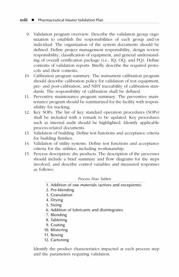
15. Process description: dry products. The description of the processesshould include a brief summary and flow diagrams for the stepsinvolved, and describe control variables and measured responsesas follows:
Identify the product characteristics impacted at each process stepand the parameters requiring validation.
Process Flow Tablets
1. Addition of raw materials (actives and excepients)2. Pre-blending3. Granulation4. Drying5. Sizing6. Addition of lubricants and disintegrates7. Blending8. Tableting9. Coating
10. Blistering11. Boxing12. Cartoning
SL3305_ FM_fm Page xviii Thursday, November 8, 2001 3:07 PM
�
xix
16. Process description: liquid and semisolid products. Apply a similarapproach as defined in Step 15 and as appropriate to the processrequirement.
17. Process description: parenterals. Apply a similar approach asdefined in Step 15 and as appropriate to the process requirement.
18. Qualification of process equipment. Define test functions andacceptance criteria for major equipment. A comprehensive listidentifying the protocols required shall be finalized, or alternatively,shall be provided by the validation program overview in Step 9.
19. Validation of support processes. Define test functions and acceptancecriteria for critical validation support processes such as washing ofcomponents, sterilization of components, depyrogenation, etc.
20. Quality assurance/control laboratory validation. Describe the vali-dation approach for the laboratory equipment and test methods.Define test functions and acceptance criteria.
21. cGMP procedures and programs. Define the following programs:engineering change control, calibration, preventive maintenance,personal training, facility cleaning and sanitization, environmentalmonitoring, HEPA filter integrity testing, etc.
22. Validation schedule. Provide time line chart for the on-time com-pletion of validation tasks of equipment, utilities, processes, clean-ing etc., to ensure compliance with government regulations, quality,and cost reduction.
23. Drawings. Identify all key drawings related to the civil layout,utilities, personnel flow, materials flow, etc. Assign a number toeach drawing.
CD-ROM
An electronic copy of the generic Validation Master Plan is provided. Seethe inside back cover of this book for the CD-ROM.
SL3305_ FM_fm Page xix Thursday, November 8, 2001 3:07 PM
xx
�
Pharmaceutical Master Validation Plan
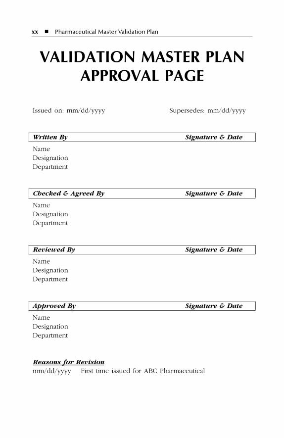
VALIDATION MASTER PLAN APPROVAL PAGE
Issued on: mm/dd/yyyy Supersedes: mm/dd/yyyy
Written By Signature & Date
NameDesignationDepartment
Checked & Agreed By Signature & Date
NameDesignationDepartment
Reviewed By Signature & Date
NameDesignationDepartment
Approved By Signature & Date
NameDesignationDepartment
Reasons for Revision
mm/dd/yyyy First time issued for ABC Pharmaceutical
SL3305_ FM_fm Page xx Thursday, November 8, 2001 3:07 PM
xxi
ABOUT THE BOOK
This book and CD-ROM take into account all major international regula-tions, such as FDA, cGMP, GLP, GCP and industry standard ISO 9000, tobe in compliance with documentation guidelines. No other book in printdeals exclusively with the key elements of a Validation Master Plan for apharmaceutical plant and provides a hands-on template to be tailor madeto achieve documentation compliance for FDA inspection.
The Validation Master Plan (VMP) is written to provide explicit instruc-tions on how to achieve it for anyone responsible for writing and executinga VMP for drug, drug-device combination, diagnostic, pharmaceutical,biotechnology, and bulk pharmaceutical chemicals products. Included isthe ready-to-use template that one can immediately use as one’s ownwithout reinventing the wheel, thus saving time and money withoutmissing any critical element.
This book provides instant answers to validation engineers, validationspecialists, quality professionals, quality assurance auditors, and protocolwriters regarding what should be made part of the VMP and how toenhance productivity.
Introduction
�
Validation Master Plan
�
Resource requirement estimates
�
Writing a Validation Master Plan
�
Elements of Validation Master Plan
�
Vulnerability assessments
�
CD-ROM
�
Decision making
� Acknowledgment� Disclaimer
SL3305_ FM_fm Page xxi Thursday, November 8, 2001 3:07 PM
xxii � Pharmaceutical Master Validation Plan
Master Validation Plan
Plan approval Reasons for revision
Introduction Project description What is a Validation Master Plan Scope of Validation Master Plan Definition for the term validation Validation team member Validation team responsibility
Concept of qualification/validation Fundamentals Concept of a validation life cycle Elements of validation Documentation format of qualification programs Numbering system
Revalidation Facility description Description of building
Dry Production facility Liquid and semisolid production facility Parenterals production facility
Equipment description Dry production Liquid and semi-solid production Parenterals production Over printing area Quality assurance (in-process) Product development laboratories
HVAC description Dry production facility Liquid and semi-solid production facility Parenterals production facility Over printing area Quality control Quality assurance (in-process)Product development laboratories
Utilities description Validation program overview
Validation project management Validation responsibilities Design and validability review
SL3305_ FM_fm Page xxii Thursday, November 8, 2001 3:07 PM
� xxiii
Enhanced turn-over package Installation qualification protocols Operational qualification protocols Change control initiation Cycle development Performance qualification protocol Process validation protocols Validation final reports Validation package Certificate for use in manufacturing Required protocols and procedures for dry production Required protocols and procedures for liquid and semisolid
products Required protocols and procedures for parenterals production
Calibration program summary Preventive maintenance program summary Key SOPs Validation of building Test functions and acceptance criteria
Civil work Drainage system
Validation of utility systems Test functions and acceptance criteria
Plant steam Pure steam Water for injection Compressed air Nitrogen (N2) Carbon dioxide (CO2) Heating ventilation and air conditioning (HVAC) Emergency power
Process description: dry products Process flow, variables, and responses: tablets Process flow, variables, and responses: powder for suspension Process flow, variables, and responses: capsules
Process description: liquids and semisolid products Process flow, variables, and responses: syrups, suspension, and
drops products Process flow, variables, and responses: cream, ointment, and
suppository products Process description: parenterals product
Process flow, variables, and responses: aseptic fill products
SL3305_ FM_fm Page xxiii Thursday, November 8, 2001 3:07 PM
xxiv � Pharmaceutical Master Validation Plan
Process flow, variables, and responses: aseptic fill ready-to-usedisposable syringes
Process flow, variables, and responses: terminal sterilizationproducts
Process flow, variables, and responses: lyophilized products Qualification of process equipment test functions and acceptance
criteria Commuting mill Oven V-shell blender Tablet compression Capsulation Powder filling Capsule polisher Tablet coating Syrup manufacturing vessel Suspension manufacturing vessel Drops manufacturing vessel Mixer Emulsifying mixer Filter press Cream/ointment/suppository manufacturing vessel Syrup, suspension, and drop filling machine Cream and ointment filling machine Suppository filling machine Labeling machine Capping machine Cartonator Shrink wrapping machine Over printing machine Trays and rack washer Autoclave (steam sterilizer) Hot air tunnel (dry heat sterilizer) Vials/ampoules washing machine Vials/ampoules/syringes filling Freeze dryer (lyophilizer) Laminar flow unit Pass-through
Validation of support processes test functions and acceptancecriteria
Washing of components Sterilization of components Depyrogenation of components
SL3305_ FM_fm Page xxiv Thursday, November 8, 2001 3:07 PM
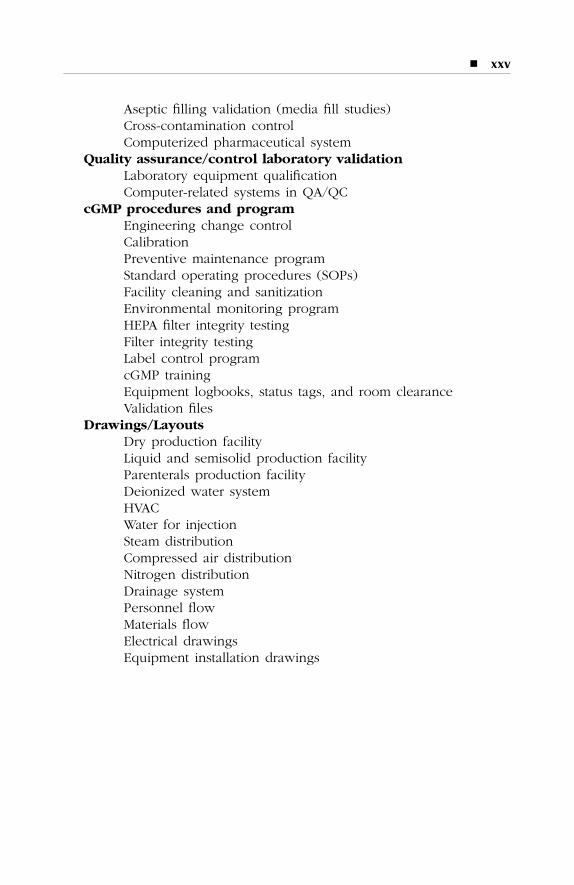
� xxv
Aseptic filling validation (media fill studies) Cross-contamination control Computerized pharmaceutical system
Quality assurance/control laboratory validation Laboratory equipment qualification Computer-related systems in QA/QC
cGMP procedures and program Engineering change control Calibration Preventive maintenance program Standard operating procedures (SOPs) Facility cleaning and sanitization Environmental monitoring program HEPA filter integrity testing Filter integrity testing Label control program cGMP training Equipment logbooks, status tags, and room clearance Validation files
Drawings/Layouts Dry production facility Liquid and semisolid production facility Parenterals production facility Deionized water system HVAC Water for injection Steam distribution Compressed air distribution Nitrogen distribution Drainage system Personnel flow Materials flow Electrical drawings Equipment installation drawings
SL3305_ FM_fm Page xxv Thursday, November 8, 2001 3:07 PM

SL3305_ FM_fm Page xxvi Thursday, November 8, 2001 3:07 PM
xxvii
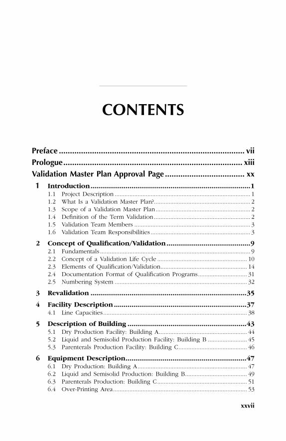
CONTENTS
Preface .................................................................................... viiPrologue................................................................................. xiiiValidation Master Plan Approval Page .................................... xx1 Introduction..................................................................................1
1.1 Project Description ................................................................................... 11.2 What Is a Validation Master Plan?........................................................... 21.3 Scope of a Validation Master Plan.......................................................... 21.4 Definition of the Term Validation........................................................... 21.5 Validation Team Members ....................................................................... 31.6 Validation Team Responsibilities ............................................................. 3
2 Concept of Qualification/Validation...........................................92.1 Fundamentals ............................................................................................ 92.2 Concept of a Validation Life Cycle ....................................................... 102.3 Elements of Qualification/Validation..................................................... 142.4 Documentation Format of Qualification Programs.............................. 312.5 Numbering System ................................................................................. 32
3 Revalidation ................................................................................35
4 Facility Description ....................................................................374.1 Line Capacities........................................................................................ 38
5 Description of Building .............................................................435.1 Dry Production Facility: Building A...................................................... 445.2 Liquid and Semisolid Production Facility: Building B ........................ 455.3 Parenterals Production Facility: Building C.......................................... 46
6 Equipment Description..............................................................476.1 Dry Production: Building A................................................................... 476.2 Liquid and Semisolid Production: Building B...................................... 496.3 Parenterals Production: Building C....................................................... 516.4 Over-Printing Area.................................................................................. 53
SL3305_ FM_fm Page xxvii Thursday, November 8, 2001 3:07 PM
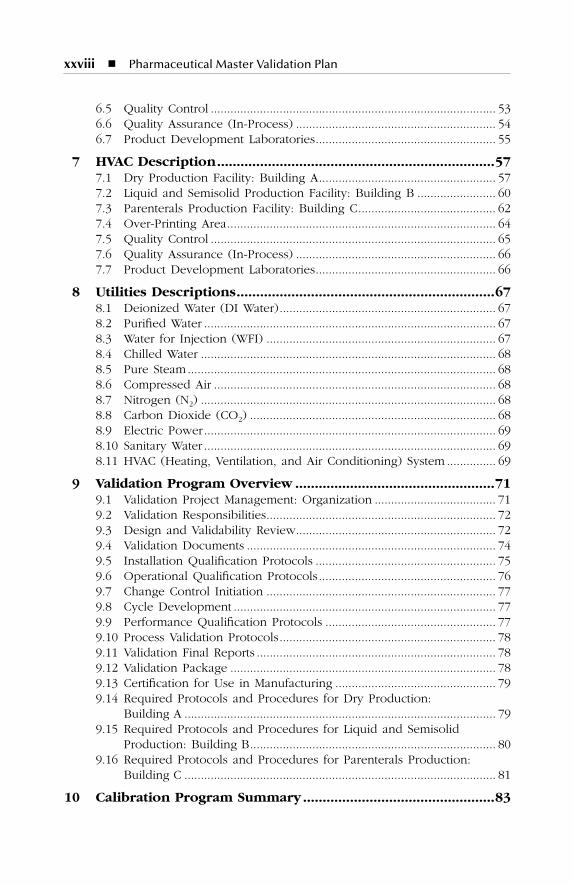
xxviii � Pharmaceutical Master Validation Plan
6.5 Quality Control ....................................................................................... 536.6 Quality Assurance (In-Process) ............................................................. 546.7 Product Development Laboratories....................................................... 55
7 HVAC Description.......................................................................577.1 Dry Production Facility: Building A...................................................... 577.2 Liquid and Semisolid Production Facility: Building B ........................ 607.3 Parenterals Production Facility: Building C.......................................... 627.4 Over-Printing Area.................................................................................. 647.5 Quality Control ....................................................................................... 657.6 Quality Assurance (In-Process) ............................................................. 667.7 Product Development Laboratories....................................................... 66
8 Utilities Descriptions..................................................................678.1 Deionized Water (DI Water).................................................................. 678.2 Purified Water ......................................................................................... 678.3 Water for Injection (WFI) ...................................................................... 678.4 Chilled Water .......................................................................................... 688.5 Pure Steam .............................................................................................. 688.6 Compressed Air ...................................................................................... 688.7 Nitrogen (N2) .......................................................................................... 688.8 Carbon Dioxide (CO2) ........................................................................... 688.9 Electric Power......................................................................................... 698.10 Sanitary Water ......................................................................................... 698.11 HVAC (Heating, Ventilation, and Air Conditioning) System ............... 69
9 Validation Program Overview ...................................................719.1 Validation Project Management: Organization ..................................... 719.2 Validation Responsibilities...................................................................... 729.3 Design and Validability Review............................................................. 729.4 Validation Documents ............................................................................ 749.5 Installation Qualification Protocols ....................................................... 759.6 Operational Qualification Protocols...................................................... 769.7 Change Control Initiation ...................................................................... 779.8 Cycle Development ................................................................................ 779.9 Performance Qualification Protocols .................................................... 779.10 Process Validation Protocols.................................................................. 789.11 Validation Final Reports ......................................................................... 789.12 Validation Package ................................................................................. 789.13 Certification for Use in Manufacturing ................................................. 799.14 Required Protocols and Procedures for Dry Production:
Building A ............................................................................................... 799.15 Required Protocols and Procedures for Liquid and Semisolid
Production: Building B........................................................................... 809.16 Required Protocols and Procedures for Parenterals Production:
Building C ............................................................................................... 81
10 Calibration Program Summary .................................................83
SL3305_ FM_fm Page xxviii Thursday, November 8, 2001 3:07 PM
� xxix
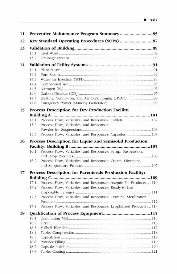
11 Preventive Maintenance Program Summary ...........................85
12 Key Standard Operating Procedures (SOPs) ...........................87
13 Validation of Building ................................................................8913.1 Civil Work............................................................................................. 8913.2 Drainage System................................................................................... 90
14 Validation of Utility Systems .....................................................9114.1 Plant Steam........................................................................................... 9114.2 Pure Steam............................................................................................ 9214.3 Water for Injection (WFI) .................................................................... 9314.4 Compressed Air .................................................................................... 9514.5 Nitrogen (N2) ........................................................................................ 9614.6 Carbon Dioxide (CO2) ......................................................................... 9714.7 Heating, Ventilation, and Air Conditioning (HVAC).......................... 9814.8 Emergency Power (Standby Generator)............................................. 99
15 Process Description for Dry Production Facility: Building A..................................................................................10115.1 Process Flow, Variables, and Responses: Tablets ........................... 10215.2 Process Flow, Variables, and Responses:
Powder for Suspensions .................................................................... 10315.3 Process Flow, Variables, and Responses: Capsules ........................ 104
16 Process Description for Liquid and Semisolid Production Facility: Building B ...................................................................10516.1 Process Flow, Variables, and Responses: Syrup, Suspension,
and Drop Products ............................................................................ 10616.2 Process Flow, Variables, and Responses: Cream, Ointment,
and Suppository Products ................................................................. 107
17 Process Description for Parenterals Production Facility:Building C..................................................................................10917.1 Process Flow, Variables, and Responses: Aseptic Fill Products..... 11017.2 Process Flow, Variables, and Responses: Ready-to-Use
Disposable Syringes ........................................................................... 11117.3 Process Flow, Variables, and Responses: Terminal Sterilization
Products .............................................................................................. 11217.4 Process Flow, Variables, and Responses: Lyophilized Products .... 113
18 Qualification of Process Equipment.......................................11518.1 Commuting Mill.................................................................................. 11518.2 Dryer ................................................................................................... 11618.3 V-Shell Blender................................................................................... 11718.4 Tablet Compression ........................................................................... 11818.5 Capsulation ......................................................................................... 11918.6 Powder Filling .................................................................................... 11918.7 Capsule Polisher................................................................................. 12018.8 Tablet Coating .................................................................................... 121
SL3305_ FM_fm Page xxix Thursday, November 8, 2001 3:07 PM

xxx � Pharmaceutical Master Validation Plan
18.9 Syrup Manufacturing Vessel .............................................................. 12218.10 Suspension Manufacturing Vessel ..................................................... 12318.11 Drops Manufacturing Vessel.............................................................. 12418.12 Mixer ................................................................................................... 12518.13 Emulsifying Mixer .............................................................................. 12618.14 Filter Press .......................................................................................... 12718.15 Cream/Ointment/Suppository Manufacturing Vessel....................... 12818.16 Syrup, Suspension, and Drop Filling Machine................................ 12918.17 Cream and Ointment Filling Machine .............................................. 13018.18 Suppository Filling Machine.............................................................. 13018.19 Labeling Machine ............................................................................... 13118.20 Capping Machine ............................................................................... 13218.21 Cartonator ........................................................................................... 13318.22 Shrink-Wrapping Machine ................................................................. 13418.23 Over-Printing Machine....................................................................... 13418.24 Trays and Rack Washer ..................................................................... 13518.25 Autoclave (Steam Sterilizer) .............................................................. 13618.26 Hot Air Tunnel (Dry Heat Sterilizer)................................................ 13818.27 Vials/Ampoules Washing Machine.................................................... 13918.28 Vials/Ampoules/Syringes Filling Machine ........................................ 14018.29 Freeze Dryer (Lyophilizer) ................................................................ 14118.30 Laminar Flow Unit ............................................................................. 14318.31 Pass-Through ..................................................................................... 144
19 Validation of Support Processes .............................................14719.1 Washing of Components ................................................................... 14719.2 Sterilization of Components .............................................................. 14819.3 Depyrogenation of Components ...................................................... 15019.4 Aseptic Filling Validation (Media Fill Studies)................................. 15119.5 Cross-Contamination Control ............................................................ 15219.6 Computerized Pharmaceutical System.............................................. 153
20 Quality Assurance/Control Laboratory Validation ................15520.1 Laboratory Equipment Qualification................................................. 15520.2 Computer-Related Systems in the QA/QC Laboratory.................... 156
21 cGMP Procedures and Programs ............................................15721.1 Engineering Change Control ............................................................. 15721.2 Calibration........................................................................................... 15721.3 Preventive Maintenance Program ..................................................... 15821.4 Standard Operating Procedure (SOPs)............................................. 15821.5 Facility Cleaning and Sanitization..................................................... 15921.6 Environmental Monitoring Program ................................................. 15921.7 HEPA Filter Integrity Testing............................................................. 15921.8 Filter Integrity Testing........................................................................ 16021.9 Label Control Program ...................................................................... 16021.10 cGMP Training.................................................................................... 16121.11 Equipment Logbook, Status Tags, and Room Clearance Checklists.... 16121.12 Validation Files ................................................................................... 161
SL3305_ FM_fm Page xxx Thursday, November 8, 2001 3:07 PM
� xxxi
22 Validation Schedule ..................................................................163
23 Drawings for ABC Pharmaceutical Plant ...............................165
Recommended Reading....................................................................169
Index..................................................................................................171
SL3305_ FM_fm Page xxxi Thursday, November 8, 2001 3:07 PM

SL3305_ FM_fm Page xxxii Thursday, November 8, 2001 3:07 PM

1
1
INTRODUCTION
1.1 PROJECT DESCRIPTION
This Validation Master Plan (VMP) specifies and coordinates all qualifi-cation/validation activities to ensure the production of pharmaceuticalproducts according to accepted international standards. It also specifiesthe responsibilities for validation procedures and helps to plan thenecessary activities.
The plant is designed to produce oral solid dosage forms as well asliquid dosage forms, ointments, creams, suppositories, and sterile inject-able products.
The production of each product group is divided into the processingstages listed below. The general production stages for all products are:
�
Receipt of raw materials and sampling
�
Interim storage of raw materials
�
Weighing
�
Manufacturing
�
Packaging
�
Storage of finished product
�
Dispatch
SL3305_C01_fm Page 1 Thursday, November 8, 2001 3:09 PM
2
�
Pharmaceutical Master Validation Plan
To ensure the manufacturing of pharmaceutical products in ABC Phar-maceutical according to international standards, there are several guide-lines that are considered for the planning, construction, start-up, andvalidation of the buildings, equipment, and processes.
1.2 WHAT IS A VALIDATION MASTER PLAN?
A Validation Master Plan (VMP) is a comprehensive document describingthe applicable validation requirements for the facility, and providing aplan for meeting those requirements.
1.3 SCOPE OF A VALIDATION MASTER PLAN
The Validation Master Plan (VMP) includes all relevant aspects relating tothe production of pharmaceuticals in the production facility at ABC Phar-maceutical. The principles of validation, the organization of qualificationand validation, and the design and nomenclature of the documentationand equipment are also described. The VMP covers all facilities used inthe production of tablets, liquids, ointments, creams, suppositories, andsterile products; the facilities for storing raw materials, interim and finishedproducts, storage, services, and the rooms for staff.
1.4 DEFINITION OF THE TERM VALIDATION
Validation
is documented evidence that provides a high degree of assur-ance that a specific process will consistently produce a product that meetsits predetermined specifications and quality attributes.
After the requirement for each aspect is determined, the responsibleengineers complete the design and it is again reviewed by the validationteam. After the approved designs are constructed and/or installed, thevalidation cycle continues with the preparation and execution of thevalidation documents.
Validation is a systematic approach to gathering and analyzing suffi-cient data that will give reasonable assurance (documented evidence),based on scientific judgment, that a process, when operating withinspecified parameters, will consistently produce results within predeter-mined specifications.
SL3305_C01_fm Page 2 Thursday, November 8, 2001 3:09 PM
Introduction
�
3
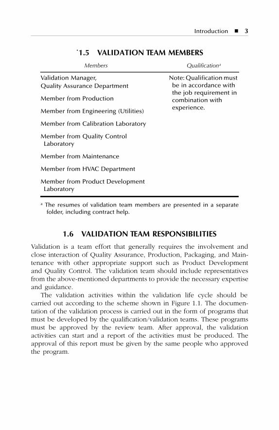
˙1.5 VALIDATION TEAM MEMBERS
1.6 VALIDATION TEAM RESPONSIBILITIES
Validation is a team effort that generally requires the involvement andclose interaction of Quality Assurance, Production, Packaging, and Main-tenance with other appropriate support such as Product Developmentand Quality Control. The validation team should include representativesfrom the above-mentioned departments to provide the necessary expertiseand guidance.
The validation activities within the validation life cycle should becarried out according to the scheme shown in Figure 1.1. The documen-tation of the validation process is carried out in the form of programs thatmust be developed by the qualification/validation teams. These programsmust be approved by the review team. After approval, the validationactivities can start and a report of the activities must be produced. Theapproval of this report must be given by the same people who approvedthe program.
Members Qualification
a
Validation Manager, Note: Qualification must be in accordance with the job requirement in combination with experience.
Quality Assurance Department
Member from Production
Member from Engineering (Utilities)
Member from Calibration Laboratory
Member from Quality Control Laboratory
Member from Maintenance
Member from HVAC Department
Member from Product Development Laboratory
a
The resumes of validation team members are presented in a separatefolder, including contract help.
SL3305_C01_fm Page 3 Thursday, November 8, 2001 3:09 PM
4
�
Pharmaceutical Master Validation Plan
If test procedures do not fulfill acceptance criteria, the review teammust decide whether or not tests must be repeated or test specificationsmust be edited. The review team can decide whether or not test results,even if they will not fulfill acceptance criteria, should be accepted as“within specification.” (See Figure 1.2.)
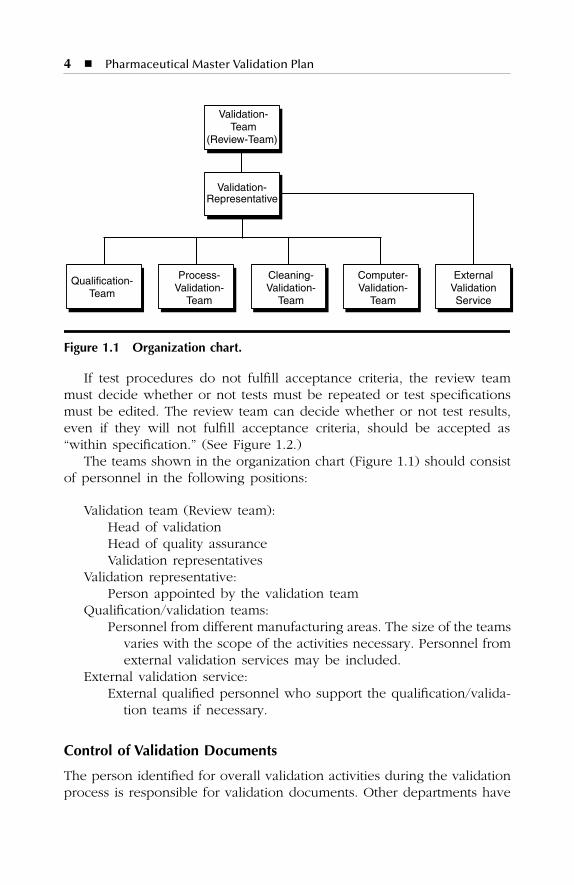
The teams shown in the organization chart (Figure 1.1) should consistof personnel in the following positions:
Validation team (Review team):Head of validationHead of quality assuranceValidation representatives
Validation representative:Person appointed by the validation team
Qualification/validation teams:Personnel from different manufacturing areas. The size of the teams
varies with the scope of the activities necessary. Personnel fromexternal validation services may be included.
External validation service:External qualified personnel who support the qualification/valida-
tion teams if necessary.
Control of Validation Documents
The person identified for overall validation activities during the validationprocess is responsible for validation documents. Other departments have
Figure 1.1 Organization chart.
Qualification-Team
Cleaning-Validation-
Team
Process-Validation-
Team
Computer-Validation-
Team
Validation- Representative
Validation-Team
(Review-Team)
ExternalValidationService
SL3305_C01_fm Page 4 Thursday, November 8, 2001 3:09 PM
Introduction
�
5
access to these documents during the validation process so that they canfurther develop validation documentation. At the end of all validationactivities, the documents are stored and controlled by the validationresponsible. The updating of documentation is done during the Changeor Revalidation procedure. This is also valid for documents from externalvalidation services. The validation responsible is responsible for the dis-tribution of updated documents.
Figure 1.2 Testing and approving procedures.
Work Out theProgram
Validation-Team
Testing +Approving
Review-Team Editing Validation-
Team
OK?
Carry Out theProgram
Validation-Team
AcceptanceCriteria
Fulfilled?
No
Check of TestSpecification
Review-Team
Repeat TestProcedure?
Edit TestSpecifications?
Approvalof Reports
Review-Team
No
No
Yes
Yes
Yes
Yes
No
SL3305_C01_fm Page 5 Thursday, November 8, 2001 3:09 PM
6
�
Pharmaceutical Master Validation Plan
The Engineering department is responsible for the technical documen-tation, for example, manuals, inspection reports, maintenance reports,specification sheets, etc. These documents are stored and updated bypersonnel from this department.
Quality Assurance
Validation officers from Quality Assurance (QA) coordinate the entirevalidation process by scheduling meetings and discussions with the vali-dation team, preparing the validation protocols, monitoring the validationprocess, compiling and analyzing validation data and test results, andpreparing the Final Report. All documentation associated with validationshould be reviewed by the QA Manager for completeness and compliancewith cGMP requirements.
Production
A validation team member from the Production department is responsibleto participate in performing the validation steps during manufacturingprocesses and equipment qualification. This department should preparethe necessary SOPs for the new process or equipment and assist in thecollection of validation data.
Packaging
A validation team member from the Packaging department is responsibleto participate in performing the validation steps during packaging pro-cesses and equipment qualification. The Packaging department shouldprepare the necessary SOPs for the new packaging process or equipmentand assist in the collection of validation data.
Utilities/Calibration/HVAC
A validation team member from the Maintenance department participatesin performing the validation; defining the necessary equipment specifica-tions, limitations, capacity, calibration, and maintenance requirements; andproviding the necessary training on the proper operation and maintenanceof the equipment. The Maintenance department should be responsible forproviding the necessary utilities and equipment accessories.
In some cases, the Maintenance department is required to participatein equipment installation and operational qualification and providetechnical support to ensure proper and efficient function during thevalidation process.
SL3305_C01_fm Page 6 Thursday, November 8, 2001 3:09 PM
Introduction
�
7
Quality Control
A validation team member from the Quality Control department is respon-sible for providing the necessary support for sampling, testing, and report-ing of test results for validation. A support group in Quality Control shouldalso perform the microbiological testing and environmental monitoringduring the validation process.
Product Development Laboratory
A validation team member from Product Development Laboratories isresponsible for defining the process (new product or process) to bevalidated and for providing technical assistance to the validation team bydefining specifications, limits, and manufacturing methods.
SL3305_C01_fm Page 7 Thursday, November 8, 2001 3:09 PM

SL3305_C01_fm Page 8 Thursday, November 8, 2001 3:09 PM
9
2
CONCEPT OF QUALIFICATION/VALIDATION
2.1 FUNDAMENTALS
The aim of production facilities and processes qualification/validation inthe ABC Pharmaceutical facility is to establish and provide documentaryevidence that:
�
The facilities, equipment, and processes have been designed inaccordance with the requirements of current GMP.
�
The facilities and the equipment have been built and installed incompliance with their design specifications.
�
The facilities and equipment operate in accordance with theirdesign specifications to repeatedly and reliably produce a finishedproduct of the required quality.
To fulfill these requirements, a complete program for validation has beendeveloped for ABC Pharmaceutical Company to ensure that all processesand equipment affecting the quality, integrity, safety, and efficacy of thepharmaceutical product are qualified and validated.
With the successful conclusion of validation, the ABC PharmaceuticalCompany management can prove that all pharmaceutical products pro-duced in the validated plant are unobjectionable, suitable for use, andcorrespond to the requirements of the product licence.
The concept of validation in this master plan covers the followingfields of activity.
�
Qualification of buildings, rooms, and supply systems
�
Qualification of equipment and service units
�
Validation of computer systems
SL3305_C02_fm Page 9 Thursday, November 8, 2001 3:10 PM
10
�
Pharmaceutical Master Validation Plan
�
Validation of production processes
�
Validation of cleaning processes
�
Periodic revalidation within the scope of a change control plan
All necessary activities and responsibilities for the qualification and vali-dation are controlled and specified in this Validation Master Plan. Everystep of the described validation program for facilities, equipment, pro-cesses, process controls, and cleaning is in accordance with the currentEuropean Community Guidelines for GMP and FDA, and the cGMPguideline for finished pharmaceutical manufacturers. All requirements inthese directives are fulfilled in this validation process.
In manufacturing facilities, validation test procedures are used to val-idate equipment and processes that may influence product quality. Thetests for validation are used in accordance with approved written qualifi-cation procedures. The approval for these procedures is given by repre-sentatives from Quality Management, Production, and Engineering. Duringrealization of this program, all activities will be documented so that theplant operates in accordance with the requirements of cGMP and withindesign specifications. At the end of the program, a review team will verifyand approve the documented results.
The Validation Report will be the final document of all validationactivities. The Validation Report includes the reports for:
�
Qualification
�
Computer validation
�
Process validation
�
Cleaning validation
To ensure a continuous validation status of facilities, processes, andprocess controls, continuous monitoring of the normal production condi-tions is necessary — as is the maintenance, calibration, and revalidationof the validated systems.
2.2 CONCEPT OF A VALIDATION LIFE CYCLE
2.2.1 Prospective Validation Life Cycle
Establishing documented evidence prior to process implementation thata system does what it proposed to do based on preplanned protocols.
The life cycle for prospective validation is divided into the followingsteps (Figure 2.1):
1. Validation Master Plan (VMP)2. Design Qualification (DQ)
SL3305_C02_fm Page 10 Thursday, November 8, 2001 3:10 PM
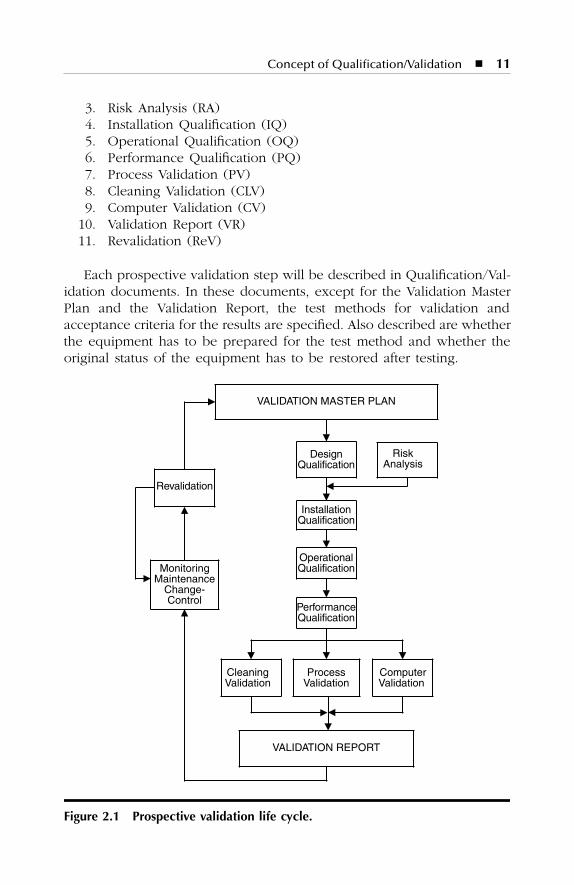
Concept of Qualification/Validation
�
11
3. Risk Analysis (RA)4. Installation Qualification (IQ)5. Operational Qualification (OQ)6. Performance Qualification (PQ)7. Process Validation (PV)8. Cleaning Validation (CLV)9. Computer Validation (CV)
10. Validation Report (VR)11. Revalidation (ReV)
Each prospective validation step will be described in Qualification/Val-idation documents. In these documents, except for the Validation MasterPlan and the Validation Report, the test methods for validation andacceptance criteria for the results are specified. Also described are whetherthe equipment has to be prepared for the test method and whether theoriginal status of the equipment has to be restored after testing.
Figure 2.1 Prospective validation life cycle.
DesignQualification
InstallationQualification
PerformanceQualification
VALIDATION REPORT
VALIDATION MASTER PLAN
RiskAnalysis
MonitoringMaintenance
Change-Control
Revalidation
ProcessValidation
ComputerValidation
CleaningValidation
OperationalQualification
SL3305_C02_fm Page 11 Thursday, November 8, 2001 3:10 PM
12
�
Pharmaceutical Master Validation Plan
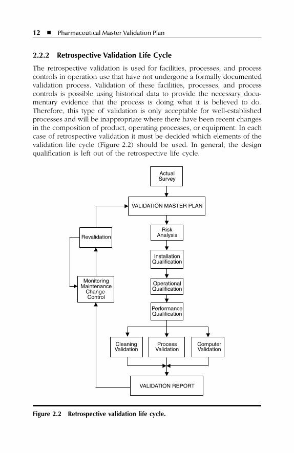
2.2.2 Retrospective Validation Life Cycle
The retrospective validation is used for facilities, processes, and processcontrols in operation use that have not undergone a formally documentedvalidation process. Validation of these facilities, processes, and processcontrols is possible using historical data to provide the necessary docu-mentary evidence that the process is doing what it is believed to do.Therefore, this type of validation is only acceptable for well-establishedprocesses and will be inappropriate where there have been recent changesin the composition of product, operating processes, or equipment. In eachcase of retrospective validation it must be decided which elements of thevalidation life cycle (Figure 2.2) should be used. In general, the designqualification is left out of the retrospective life cycle.
Figure 2.2 Retrospective validation life cycle.
RiskAnalysis
InstallationQualification
PerformanceQualification
VALIDATION REPORT
VALIDATION MASTER PLAN
MonitoringMaintenance
Change-Control
Revalidation
ProcessValidation
ComputerValidation
ActualSurvey
CleaningValidation
OperationalQualification
SL3305_C02_fm Page 12 Thursday, November 8, 2001 3:10 PM
Concept of Qualification/Validation
�
13
The life cycle for retrospective validation is divided into the fol-lowing steps:
1. Actual survey of facilities, processes, and process controls2. Validation Master Plan (VMP)3. Design Qualification (DQ)4. Risk Analysis (RA)5. Installation Qualification (IQ)6. Operational Qualification (OQ)7. Performance Qualification (PQ)8. Process Validation (PV)9. Cleaning Validation (CLV)
10. Computer Validation (CV)11. Validation Report (VR)12. Revalidation (ReV)
2.2.3 Concurrent Validation Life Cycle
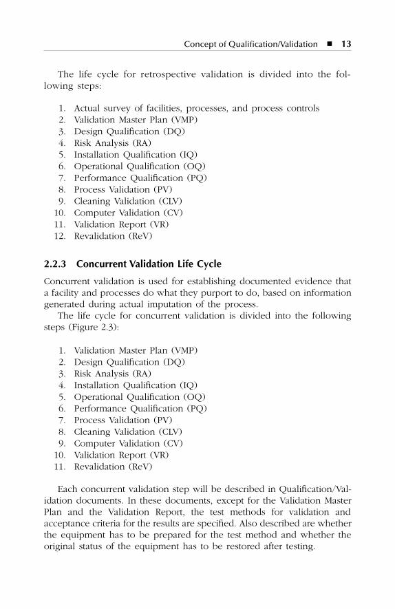
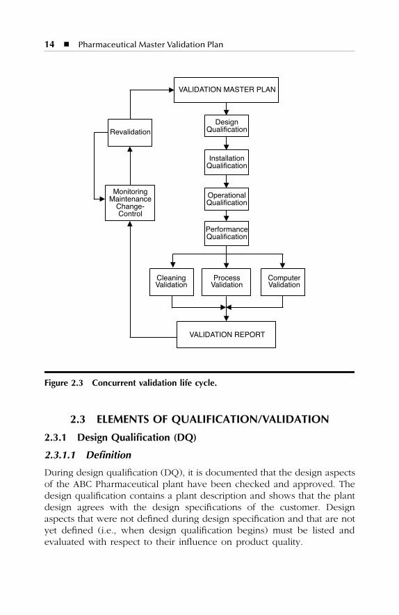
Concurrent validation is used for establishing documented evidence thata facility and processes do what they purport to do, based on informationgenerated during actual imputation of the process.
The life cycle for concurrent validation is divided into the followingsteps (Figure 2.3):
1. Validation Master Plan (VMP)2. Design Qualification (DQ)3. Risk Analysis (RA)4. Installation Qualification (IQ)5. Operational Qualification (OQ)6. Performance Qualification (PQ)7. Process Validation (PV)8. Cleaning Validation (CLV)9. Computer Validation (CV)
10. Validation Report (VR)11. Revalidation (ReV)
Each concurrent validation step will be described in Qualification/Val-idation documents. In these documents, except for the Validation MasterPlan and the Validation Report, the test methods for validation andacceptance criteria for the results are specified. Also described are whetherthe equipment has to be prepared for the test method and whether theoriginal status of the equipment has to be restored after testing.
SL3305_C02_fm Page 13 Thursday, November 8, 2001 3:10 PM
14
�
Pharmaceutical Master Validation Plan
2.3 ELEMENTS OF QUALIFICATION/VALIDATION
2.3.1 Design Qualification (DQ)
2.3.1.1 Definition
During design qualification (DQ), it is documented that the design aspectsof the ABC Pharmaceutical plant have been checked and approved. Thedesign qualification contains a plant description and shows that the plantdesign agrees with the design specifications of the customer. Designaspects that were not defined during design specification and that are notyet defined (i.e., when design qualification begins) must be listed andevaluated with respect to their influence on product quality.
Figure 2.3 Concurrent validation life cycle.
DesignQualification
InstallationQualification
PerformanceQualification
VALIDATION REPORT
VALIDATION MASTER PLAN
MonitoringMaintenanceChange-Control
Revalidation
ProcessValidation
ComputerValidation
CleaningValidation
OperationalQualification
SL3305_C02_fm Page 14 Thursday, November 8, 2001 3:10 PM
Concept of Qualification/Validation
�
15
Within the design qualification process, the design is checked to ensurethat the important aspects of GMP are fulfilled and compliance with theseimportant GMP aspects is documented. In the definition of the designqualification as well as in the further stages of the DQ process, all qualifiedpersonnel from various departments of the company must be involved.The involvement of qualified personnel is important in the process ofdesign qualification as well as in the definition of tests that must beperformed; for example, checking the technical and pharmaceuticaldemands. In subsequent stages of the validation process, the involvementof these qualified personnel will not be required to such a large extent.In this Validation Master Plan, Chapter 9 shows the qualification matrix.This matrix indicates the facilities for which a design qualification mustbe produced. Normally, when not otherwise specified, a design qualifi-cation is produced for all buildings, rooms, and process plants. However,when plants are to be validated retrospectively, no design qualificationprocess occurs.
2.3.1.2 Contents
The Design Qualification should be divided into the following sections:
�
History of DQ
�
Fundamentals
�
Purpose
�
Implementation procedure
�
Acceptance criteria
�
Tests specification
�
Summary of DQ evaluation
�
Additional design aspects
The basis of the DQ is the design specification of ABC Pharmaceutical.The DQ is done by the personnel responsible from the ABC Pharmaceu-tical Company and the plant designers. The design specifi cationsdemanded by the customer are compared with the actual design of theplant. Written evidence of this comparison is produced which confirmswhether or not the actual design agreed with the customer’s designspecifications.
Once the DQ is approved, the status of the design specifications isfrozen. From this point on, the DQ and the specifications are under thecontrol of change management.
SL3305_C02_fm Page 15 Thursday, November 8, 2001 3:10 PM
16
�
Pharmaceutical Master Validation Plan
2.3.2 Risk Analysis (RA)
2.3.2.1 Definition
The purpose of validation is to obtain written evidence that processesand equipment work within their specifications to produce products ofthe demanded quality. However, when working with processes andequipment, there are always risks that may or may not be acceptable.To prove whether or not possible risks are acceptable for the productquality, a risk analysis (RA) must be done. The purpose of the RA is toidentify critical and noncritical parts of processes and equipment. Thisrisk analysis also identifies the activities necessary for validation, main-tenance, and calibration.
The RA must be done for prospective as well as retrospective validationprocesses. For a realistic opinion of possible risks to be obtained and tocover the most relevant aspects, it is necessary to involve qualified personnelwith different specialist knowledge in the process of RA. For example, QualityControl personnel, Production personnel, Engineering personnel, etc.
In this Validation Master Plan, Chapter 9 shows the qualification matrix.This matrix indicates the processes and parts of the plant for which anRA must be produced.
2.3.2.2 Contents
The risk analysis should be divided into the following sections:
�
History of RA
�
Fundamentals
�
Purpose
�
Implementation procedure
�
Participants
�
Risk analysis
2.3.2.3 Risk Analysis Procedure
The RA is systematically carried out by personnel/departments specifiedin Section 1.5 of this master plan. Documents used for the analysis ofprocesses and equipment might include:
�
P&I diagrams
�
System descriptions
�
Manufacturer’s documentation
�
Recordings from logbooks, batch documents, etc. (for plants in use)
�
Literature
SL3305_C02_fm Page 16 Thursday, November 8, 2001 3:10 PM
Concept of Qualification/Validation
�
17
The RA procedure is divided into the following steps:
1. List of all parts of the plant and their functions2. Classification (critical or noncritical)3. Reason for classification4. Possible influence on quality parameters5. Estimation of failure probability6. List of measurements taken
2.3.3 Installation Qualification (IQ)
2.3.3.1 Definition
In the installation qualification (IQ) process, written evidence is given thatall parts of the equipment are installed according to the equipmentsupplier’s and purchase specifications. For complicated or large pieces ofequipment, it may be decided to undertake a predelivery check of theequipment at the supplier’s assembly facility. This predelivery check willalso be part of the IQ. It is documented that the operating criteria for theequipment, as installed, are in compliance with the P&I diagrams, plantfunctional specifications, and process flow diagrams.
The IQ represents the status of the plant where the completeness andcorrectness of all required documents are checked. At this point, ifnecessary, documents must be completed and corrected.
In the case of retrospective validation, processes and purchase speci-fications as well as manuals from the manufacturer of equipment are rarelyavailable. Therefore, the IQ is, for many parts, equivalent to the actualsurvey of the plant and uncompleted documentation can be replaced bythe IQ documentation.
The IQ refers as often as possible to engineering documents (e.g., P&Idiagrams, plant functional specifications, process flow diagrams, inventorylists, etc.) to avoid redundant documentation and to minimize the expen-diture of updating.
2.3.3.2 Contents
The IQ procedure is divided into the following steps:
1. History of the IQ2. Fundamentals3. Purpose4. Implementation procedure5. Identification of signatures6. Acceptance criteria
SL3305_C02_fm Page 17 Thursday, November 8, 2001 3:10 PM
18
�
Pharmaceutical Master Validation Plan
7. Description of the systems8. Specification of tests9. Results of the tests
The specifications of the test procedures should be divided into thefollowing sections:
�
Check completeness and current status of documentation
�
Check delivered equipment from manufacturer
�
Check if all parts of the plant are according to their specifications
�
Check the identity of all parts of the plant
�
Visual check of complete and craftsmanship installation of all partsof the plant
�
Check if materials used are within their specifications
2.3.3.3 IQ Process and Documentation
In the IQ process, the first documents to be written are the IQ programs.Persons responsible for the release of IQ programs are identified inChapter 9. An auditor and a witness carry out the test procedures givenin the approved IQ programs. During the test procedures, the auditor willdecide whether or not the tests’ acceptance criteria are fulfilled. Thewitness certifies by signature that the test procedures are carried out bythe auditor in accordance with their test specifications. If the IQ programsare filled in with all results of the test procedures, they become the IQreport. The persons named in Section 1.5 will approve the IQ reportsagain, and they become the final IQ documents.
2.3.4 Operational Qualification (OQ)
2.3.4.1 Definition
During the OQ process, documented evidence is given that all parts ofthe plant and equipment work within their specifications and processparameters are within the acceptance criteria. Process controls that arepart of the equipment (e.g., PLC [programmable logic controller]) will bequalified during the OQ process. Computerized process controls (i.e., forcomplex processes) should be qualified in the Computer Validation (CV)process. To ensure that the systems tested during OQ are doing whatthey are believed to do, a simulation of normal production conditionsmust be done.
The given definition of OQ is valid for retrospective validation as wellas for prospective validation.
SL3305_C02_fm Page 18 Thursday, November 8, 2001 3:10 PM
Concept of Qualification/Validation
�
19
SOPs for use, maintenance, calibration, and cleaning of the plant mustbe developed during the OQ process, as well as schedules for maintenanceand calibration. Each OQ document contains a list of required SOPs forthe use of the plant. At this point, training of the technical staff of theplant should take place. The training must be documented and checkedusing prepared forms. Within the OQ process, the calibration of measuringand controlling devices must be checked. Critical parameters and circum-stances identified in the risk analysis (RA) must be checked for conformityto the acceptance criteria.
The OQ refers as often as possible to start-up protocols and engineeringdocuments (e.g., P&I diagrams, plant functional specifications, processflow diagrams, inventory lists, etc.) to avoid redundant documentationand to minimize the expenditure of updating.
2.3.4.2 Contents
The OQ procedure is divided into the following steps:
1. History of the OQ2. Fundamentals3. Purpose4. Implementation procedure5. Description of the systems6. Measuring instruments7. Services of the processes8. Consumables9. Specification of tests
10. Results of the tests11. Malfunction protocol
To avoid extensive documentation, the specifications of the test pro-cedures in OQ should be divided into sub-sections as in the IQ procedure.An example of some essential sections is given below.
�
Purpose of test specification
�
Required equipment
�
Preparative measures
�
Testing procedures
�
Acceptance criteria
�
Data to be recorded
�
Additional measures
SL3305_C02_fm Page 19 Thursday, November 8, 2001 3:10 PM
20
�
Pharmaceutical Master Validation Plan
2.3.4.3 OQ Process and Documentation
To start the OQ process for a given part of the plant, it is necessarythat the IQ process for this part has been completed. As in the IQprocess, the first documents that must be written in the OQ process arethe OQ programs. The persons named in Section 1.5 and Chapter 9 givethe approval/release of these OQ programs. The test procedures givenin the approved OQ programs are carried out by an auditor and awitness. During test procedures, the auditor will decide whether or notthe tests acceptance criteria are fulfilled. The witness certifies by signaturethat the test procedures are carried out by the auditor in accordancewith their test specifications. If the OQ programs are filled in with allresults of the test procedures, they become the OQ report. The OQreports will be approved again by the persons named in Section 1.5 andChapter 9 and they become the final OQ document.
2.3.5 Performance Qualification (PQ)
2.3.5.1 Definition
The PQ process provides documented evidence that all parts of the plantand the processes validated produce products of the specified qualityunder conditions of normal production for a longer period of time. It isshown that product quality is within the specifications as long as thequality of raw materials stays within specification. The PQ includes criticalvariable studies, for example, by simulating conditions of upper and lowerprocessing, processing at the operating limits of the equipment, or cir-cumstances like worst-case conditions. It is shown that such conditionsshould not necessarily induce process or product failure.
In contrast to the OQ procedures where all parts of the plant andequipment are qualified separately, the PQ procedures qualify the entireplant with respect to the production process. The definition given for PQis valid for retrospective validation as well as for prospective validation.While carrying out PQ processes, all necessary SOPs (e.g., for the use orcleaning of the plant) should be approved. Values of critical and noncriticalprocess parameters recorded during PQ must be collected to evaluate theefficiency and performance of the plant.
In this Validation Master Plan, the qualification matrix is presented inChapter 9. This matrix indicates processes and parts of the plant for whicha PQ must be produced.
SL3305_C02_fm Page 20 Thursday, November 8, 2001 3:10 PM
Concept of Qualification/Validation
�
21
2.3.5.2 Contents
The PQ procedure is divided into the following steps:
1. History of the PQ2. Fundamentals3. Purpose4. Implementation procedure5. Description of the systems6. Measuring instruments7. Services of the processes8. Consumables9. Specification of tests
10. Results of the tests11. Malfunction protocol
For the same reasons as in the OQ, the specifications of the PQ testprocedures should be divided into sub-sections. Some essential sectionsare listed below.
�
Purpose of test specification� Required equipment� Preparative measures� Testing procedures� Acceptance criteria� Data to be recorded� Additional measures
2.3.5.3 PQ Process and Documentation
The OQ procedures must be completed before starting the PQ process.The PQ process and documentation are carried out in a similar mannerto the OQ process. As in OQ documentation, the PQ documents are thePQ programs, the PQ report, and the approved final PQ document. Withthis, document qualification of the plant is completed.
At this point, a summary of the activities during DQ, RA, IQ, OQ,and PQ must be written and qualification activities remaining open shouldbe listed.
SL3305_C02_fm Page 21 Thursday, November 8, 2001 3:10 PM

22 � Pharmaceutical Master Validation Plan
2.3.6 Process Validation (PV)
2.3.6.1 Definition
Process Validation (PV) ensures and provides documented evidence thatprocesses within their specified design parameters are capable of repeat-edly and reliably producing a finished product of predetermined quality.
The PV process is divided into the steps shown in Figure 2.4. First, aplan for the process validation must be developed. This process validationplan (PV plan) regulates the validation procedures for the manufacturingprocesses for each product. The process validation program is a singledocument and contains the specifications and test procedures for eachsingle product. The process validation report contains the results of eachvalidation program. In contrast to PQ documentation, where the programand report are together in one document, the validation program andreport of PV are stated in two different documents. A summary of all PVactivities is given in the final PV document at the end of the PV process.
Figure 2.4 The PV process.
Processvalidation plan
(PV-plan)
PV-program 2
PV-program 3
PV-program 1
PV- report 2 PV- report 3PV- report 1
Final PVdocument
SL3305_C02_fm Page 22 Thursday, November 8, 2001 3:10 PM

Concept of Qualification/Validation � 23
2.3.6.2 Contents of PV Plan
The PV plan contains several essential sections, for example, the pointslisted below:
� Which manufacturing processes must be validated (product matrix)� Which kind of validation (prospective, retrospective, or concurrent)
must be done� Schedule of the validation of product processes� Number of batches that must be used for validation (normally 3 to
10 batches of the quantity assigned for production)� Responsibilities
2.3.6.3 Contents of PV Program
The following points should be included in the Process Validation program:
� History of development and a description of the product (if avail-able, the development report would be useful)
� A manufacturing procedure and flowchart of the manufacturingprocess
� A list of all equipment required for production� A list of production stages that may be critical for product quality� A schedule for PV test procedures� A detailed description for all test procedures, including:
– Sampling procedure– Labeling of the samples– Test procedure– Evaluation procedure– Specifications for the intermediate and finished products– Acceptance criteria
� Responsibilities
2.3.6.4 PV Process and Documentation
All qualification procedures for equipment and services of the manufac-turing process must be completed before starting the PV process. Amanufacturing process achieves the status of “validated” if all batchesdefined in the PV plan fulfill the specifications for the intermediate andfinished products.
Schedules and other requirements for the PV process and documen-tation are stated in the PV plan document.
SL3305_C02_fm Page 23 Thursday, November 8, 2001 3:10 PM
24 � Pharmaceutical Master Validation Plan
2.3.7 Cleaning Validation (CLV)
2.3.7.1 Definition
During the CLV process, written evidence is given that specified cleaningprocedures will lead to reliable and repeatable results in the cleaning ofsurfaces with and without contact with the product. It is shown that thefollowing criteria will be fulfilled if cleaning procedures are used asspecified in cleaning SOPs:
� The concentration of active substances on product contact surfaceswill not exceed specified limits.
� The concentration of highly active substances (e.g., hormones orcytostatics) on surfaces without contact with the product will notexceed specified limits.
� The concentration of other pharmacologically active substances (e.g.,process and cleaning materials or disinfectants) in the product tofollow will not exceed specified limits
� The number of germs on product contact surfaces will not exceedspecified limits.
The procedures within the CLV process must be specified in a CLVplan. Cleaning procedures for products and processes that are very similardo not need to be individually validated. It is acceptable to select arepresentative range of similar products and processes and then to justifya validation program that addresses the critical issues relating to theselected products and processes. A single validation study can be carriedout that takes into account the relevant criteria. This practice is termed“bracketing.” The criteria for the bracketing of products and processesmust be given in the CLV plan.
For nondedicated multi-purpose equipment (i.e., equipment for theproduction of products from different defined product groups), the clean-ing procedures must be validated for each and every product group. Forsingle-purpose equipment (i.e., equipment for the production of one singleproduct), it is acceptable to visually confirm that the equipment is cleanafter batch-to-batch cleaning procedures. The validation of these proce-dures is not necessary, but it must be established that the equipment ismicrobiologically clean after these cleaning procedures and the stabilityof the product due to the reduced cleaning. For products that decomposeinto intermediate or final products, acceptance criteria for the concentrationof degradation product on the equipment inside surface must be given toensure that all validation requirements are fulfilled. The development and
SL3305_C02_fm Page 24 Thursday, November 8, 2001 3:10 PM
Concept of Qualification/Validation � 25
validation of cleaning procedures are usually part of product developmentand therefore should be validated prospectively.
Figure 2.5 illustrates the steps of the CLV process. The different pro-grams represent the selected brackets of products.
2.3.7.2 Contents of CLV Plan
The CLV plan should contain essential sections for example the pointslisted below:
� Which manufacturing processes must be validated (product matrix)� Which kind of validation (prospective, retrospective or concurrent)
must be done� Schedule of the validation of product processes� Number of batches that must be used for validation (normally three
to ten batches of the quantity assigned for production)� Responsibilities
Figure 2.5 The CLV process.
Cleaningvalidation plan
(CLV-plan)
CLV-program 2
CLV-program 3
CLV-program 1
CLV- report 2 CLV- report 3CLV- report 1
Final CLVdocument
SL3305_C02_fm Page 25 Thursday, November 8, 2001 3:10 PM
26 � Pharmaceutical Master Validation Plan
2.3.7.3 Contents of CLV Program
The following points should be included in the Cleaning Validation program:
� Purpose of validation� Responsibilities� Composition of the product (formulation)� A short master formula� A description of:
– Substance that should be detected– Cleaning procedure– Sampling method– Analytical method used– Evaluation method used for the result– Acceptance criteria
� Description of the plant to be cleaned and of the sampling locations� Description of the sampling procedure� Time between end of production and sampling� Number of test runs (test runs must be performed by qualified
personnel only)� Description of procedures necessary in the case of exceeded accep-
tance criteria
As in the PV process, the CLV program and CLV report are two separatedocuments. A final CLV document summarizes the results of all CLVactivities.
2.3.7.4 Bracketing of Products and Equipment
As shown above, similar products can be validated together on the sameequipment by selecting representative products for the validation proce-dure (“bracketing”). The Cleaning Validation procedures must be carriedout according to the critical parameters of these products.
Criteria for the selection of a representative range of similar productsinclude:
� Identical dosage form� Identical manufacturing process� Similar formulation� Properties of active substances� Similar therapeutical efficacy� Toxicity
SL3305_C02_fm Page 26 Thursday, November 8, 2001 3:10 PM
Concept of Qualification/Validation � 27
As with similar products, the production plants should be divided intosimilar plants. Plants with similar layouts and functionalities should beselected, and representative plants should be used to carry out the CleaningValidation procedures. Essential for this type of bracketing is that theselected plants will be cleaned in exactly the same way, that is, accordingto the same cleaning SOP.
2.3.8 Computer Validation (CV)
Validation of computerized systems differs from the validation processespreviously described because of the complexity and key-function in theprocess controls of such systems. Therefore, computer validation has aspecial life cycle (system development life cycle [SDLC]) that containsthe hardware and the software. The sub-sections of the SDLC are similarto the subsections of the life cycles for prospective/retrospective valida-tion processes.
2.3.8.1 Definition
The CV provides documented evidence that processes controlled bycomputerized systems are checkable and produce the specified productquality repeatedly and reliably.
The life cycle for computer validation (SDLC) contains planning, spec-ification, programming, testing, start-up, documentation, operation, check-ing, and changing. To validate the software according to the requirementsgiven above, the following activities should be part of the SDLC:
� Documentation– Project plan/application– Quality plan– User requirements– Functional specifications– User manual– System operator manual
� SDLC document standards� Risk analysis� Coding modules/setting of parameters/configuration� Planning and performing module and integration tests� Software installation� Planning and performing acceptance tests� Validation report/release� Putting out of action
SL3305_C02_fm Page 27 Thursday, November 8, 2001 3:10 PM
28 � Pharmaceutical Master Validation Plan
The comprehensive activities that must be considered for the pointslisted above include:
� Management of configuration� Failure investigation and corrective activities� Change control� Training� Responsibilities� Planning and performing of audits� Planning and performing of reviews
The life cycle for the hardware is divided into the following steps:
1. Obtaining and Installation2. Operation3. Putting out of action
The physical conditions in the computer systems’ surroundings couldhave an effect on the operation. Therefore, these conditions must becontrolled or protective measures must be taken. The physical quantitiesthat must be controlled include:
� Temperature� Humidity� Voltage stability� Smoke
Controls and protective measures must be considered during planningor modification of all rooms with computerized systems for the followingfactors:
� Aggressive gases� Voltage fluctuation� Flash of lightning� Fire� Water� Vibration� Electrostatic charge
The range of controls and protective measures should be specified foreach system separately according to the sensitivity of the system and theassociated risk.
SL3305_C02_fm Page 28 Thursday, November 8, 2001 3:10 PM
Concept of Qualification/Validation � 29
The Validation Report is the final document of all validation activities.It summarizes the essential parts of the activities and marks the end ofthe validation process. Separate reports for the validation sub-sectionslisted below must be written.
2.3.9 Validation Report
2.3.9.1 Definition
� Qualification Includes: DQ, RA, IQ, OQ, PQ� Process validation PV� Cleaning validation CLV� Computer validation CV
The Validation Report refers to these sub-sections.
2.3.9.2 Contents
A detailed discussion of the following points should be included in theValidation Report:
1. Changes and deviations of the qualification/validation activitiesfrom the documentation must be listed. The measures taken insteadmust be justified and incomplete measures must be listed.
2. Critical points found during qualification/validation that are notincluded in the risk analysis must be listed and the measures takendescribed.
3. The Validation Report must include an overview of all documen-tation, including appendices.
4. At the end of the Validation Report, a statement must be given asto whether or not the equipment and the processes have the status“qualified/validated.”
2.3.10 General Acceptance Criteria
The general acceptance criteria for the tests during IQ, OQ, and PQprocesses are listed in subsequent chapters. Specific acceptance criteriathat belong to individual test procedures are listed in each separatequalification document.
SL3305_C02_fm Page 29 Thursday, November 8, 2001 3:10 PM
30 � Pharmaceutical Master Validation Plan
2.3.10.1 Installation Qualification
1. All parts of the plant must be produced and installed according toapproved documents from the manufacturer. These could be:a. Process and service flow sheetsb. Construction/P&I diagramsc. Layout and installation specificationsd. Manufacturer’s manuals and statements
2. All documents listed must be available.3. All critical parameters, equipment models, capacity, and material
must be checked and proved against approved construction andorder specifications.
4. The performance of electrical devices must be checked.5. Manuals and lists of spare parts must be available.6. Results of equipment test runs by the manufacturer must be
satisfactory.
2.3.10.2 Operational Qualification
1. Tests must be done according to approved plans for testing andusing suitable test procedures.
2. Automatic systems (e.g., locks, alarms, or timers) that are connectedto systems to be validated must work according to their approveddesign specifications.
3. All systems and equipment parts must work reliably under normalplant operating conditions.
4. The operating status of systems that contain programmable processcontrols as part of the equipment must be equivalent to the statusdefined in the program.
5. Indicating and recording instruments used in test procedures andnormal operation must be calibrated by qualified personnel.
6. The first draft of SOPs for normal operation, control, and mainte-nance must be available.
7. The first calibration of measurement and control devices must bechecked.
8. Operational staff must be trained in their areas of responsibility.
2.3.10.3 Performance Qualification
1. The system must operate within the specifications for a longerperiod of time.
2. Samples must have the specified quality.
SL3305_C02_fm Page 30 Thursday, November 8, 2001 3:10 PM

Concept of Qualification/Validation � 31
2.4 DOCUMENTATION FORMAT OF QUALIFICATION PROGRAM
2.4.1 The Coversheet
The coversheets of the different qualification programs should be designedas follows.
The header contains the name of the pharmaceutical manufacturer, thespecific plant name, and the document number.
Each coversheet should contain the following points below the header:
� Title� Area of application� Number of pages� Version number
The author as well as the person approving the document should benamed in the next section of the coversheet. The position of these personsshould also be given. All following pages should contain the number ofpages and the current page number within the header.
2.4.2 Document Structure
The documentation of each qualification procedure is divided into twosections. The first section is a general section that includes, for example,the coversheet, the history, the table of contents, and all other pointsexcept for the test specifications and the results of the tests. The secondsection includes the test specifications and the results of the tests. Eachtest specification should be listed in the table of contents.
2.4.2.1 Header Test Specification
The structure of the test specification header is the same as the headerof the general section except for the number of pages. The pages of eachtest specification should be counted separately so that the page numberZ represents the pages of a single test specification.
ABC ABC Pharmaceutical Company Doc.-No.:
SL3305_C02_fm Page 31 Thursday, November 8, 2001 3:10 PM
32 � Pharmaceutical Master Validation Plan
2.4.3 Change of Documents
If it is necessary to edit or remove test specifications from the documen-tation, this should be done according to the following procedure.
1. The version number of the test specification should be increasedby one after the specification is edited (i.e., version V01 becomesversion V02).
2. The results of the test should be updated.3. The version number of the general section should be increased
by one.4. The history should be updated.5. The table of contents should be updated.6. The changes should be approved by qualified personnel by
signature on a new coversheet. (The approval is valid for thechanges only.)
Each qualification document could contain sections/specifications withdifferent version numbers.
2.5 NUMBERING SYSTEM
2.5.1 Numbering System for Equipment
To identify the main parts of the plant and equipment, a numbering systemis used based on the ABC Pharmaceutical Equipment Code.
2.5.2 Numbering System for Validation/Qualification Documentation
The purpose of a numbering system for the documentation is to ensurean unambiguous identification of each validation/qualification documentproduced within the field of application of the Validation Master Plan.The document number is a combination of letters and numbers with alength of 10 or 11 characters. An example of such a document numbermight be:
MM001IQ.V01 or RO001CLP.D01
The letters in the first and second positions represent the area that iscovered by the document (e.g., qualification of rooms or validation ofliquids). A legend for the first two letters is given below:
Rooms = ROManufacturing machines = MM
SL3305_C02_fm Page 32 Thursday, November 8, 2001 3:10 PM
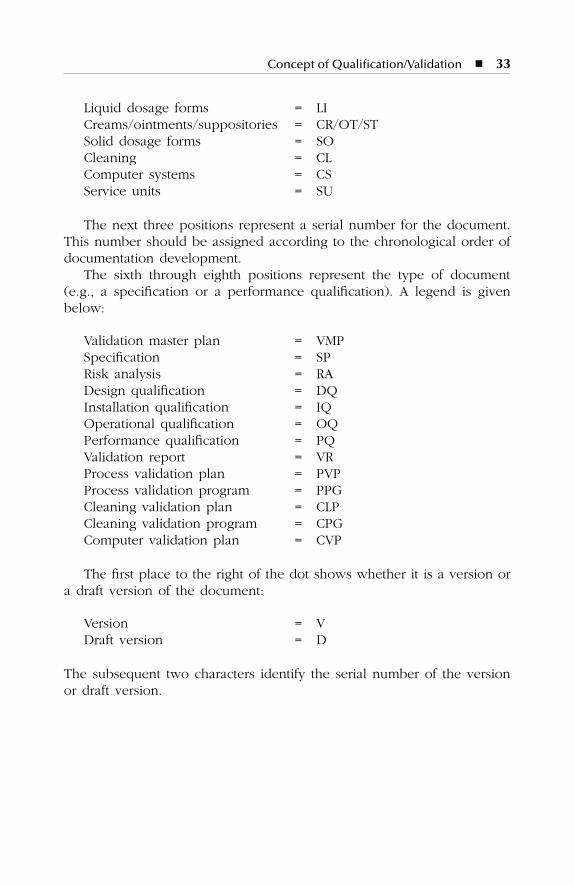
Concept of Qualification/Validation � 33
Liquid dosage forms = LICreams/ointments/suppositories = CR/OT/STSolid dosage forms = SOCleaning = CLComputer systems = CSService units = SU
The next three positions represent a serial number for the document.This number should be assigned according to the chronological order ofdocumentation development.
The sixth through eighth positions represent the type of document(e.g., a specification or a performance qualification). A legend is givenbelow:
Validation master plan = VMPSpecification = SPRisk analysis = RADesign qualification = DQInstallation qualification = IQOperational qualification = OQPerformance qualification = PQValidation report = VRProcess validation plan = PVPProcess validation program = PPGCleaning validation plan = CLPCleaning validation program = CPGComputer validation plan = CVP
The first place to the right of the dot shows whether it is a version ora draft version of the document:
Version = VDraft version = D
The subsequent two characters identify the serial number of the versionor draft version.
SL3305_C02_fm Page 33 Thursday, November 8, 2001 3:10 PM

SL3305_C02_fm Page 34 Thursday, November 8, 2001 3:10 PM
35
3
REVALIDATION
The revalidation process is essential to maintain the validated status ofthe plant, equipment, manufacturing processes, and computer systems. Itshould be as important as calibration and maintenance.
Possible reasons for starting the revalidation process include:
1. The transfer of a product from one plant to another2. Changes to the product, the plant, the manufacturing process, the
cleaning process, or other changes that could affect product quality3. The necessity of periodic checking of the validation results
Note to point 1:
For the transfer of a product from one plant to anotherqualified production plant, it is essential to revalidate the entire manufac-turing process in the new plant. It is possible that several new critical ornoncritical parameters must be determined.
Note to point 2:
In the case of the following changes, revalidation mightbe necessary:
�
Changes in the plant
�
Changes in product composition
�
Changes in manufacturing processes
�
Changes in the packaging materials
�
Changes to computer systems
�
Changes in the cleaning processes or agents
�
Changes which may affect the quality and efficacy of product
The scope of revalidation procedures depends on the extent of the changesand the effect upon the product.
Note to point 3:
Periodic revalidation must be done to ensure that nounintentional changes were made and to prove that the results of theprevious validation procedures are still valid.
SL3305_C03_fm Page 35 Thursday, November 8, 2001 3:11 PM

36
�
Pharmaceutical Master Validation Plan
The period of time between the revalidation activities is fixed by thereview team. The members of this team should consider the followingquestions:
1. Are the manufacturing processes sterile, or not?2. Are the results of the plant (product, performance) expected?3. Are maintenance and calibrating procedures carried out regularly?4. What are the critical stages of the processes?
SL3305_C03_fm Page 36 Thursday, November 8, 2001 3:11 PM
37
4
FACILITY DESCRIPTION
ABC Pharmaceutical is a medium-sized pharmaceutical industry in NewYork state and employs approximately 500 employees. The plant intendsto produce millions of units annually. The annual sales of the plant areabove U.S. $200 million. The total covered area is 50,000 square feet. ABCPharmaceutical places basic emphasis on the concept of quality and onstrict compliance with the rules of current Good Manufacturing Practice(cGMP) in all steps of manufacturing, shipping, and marketing.
The Head Office of ABC Pharmaceutical is located at Kennedy AirportRoad, approximately 60 km east of New York City, New York, U.S.A.
Building “A” of ABC Pharmaceutical is designed to manufacture dryoral products. The conventional pharmaceutical dosage forms includetablets, capsules, and powders for suspension.
Building “B” of ABC Pharmaceutical is designed to manufacture liquidsand semisolid products. The conventional pharmaceutical dosage formsinclude drops, syrups, suspensions, creams/ointments, and suppositories.
Building “C” is designed to manufacture injectables in ampoules, vials,and disposable ready-to-use syringes, and lyophilized products in vials.
The products manufactured are shipped in market packages to cus-tomers worldwide.
The plant operations are administered through the AdministrationDivision, Quality Affairs Division, and Technical Affairs Division as below:
Quality Affairs Division
�
Quality Assurance
�
Quality Control
�
Product Development Laboratory
�
RegistrationTechnical Affairs Division
�
Production
�
Packaging
SL3305_C04_fm Page 37 Thursday, November 8, 2001 3:12 PM
38
�
Pharmaceutical Master Validation Plan
�
Materials Planning
�
Maintenance
�
Shipping
�
PurchasingAdministration Division
�
Marketing
�
Personnel
�
Accounts
�
Management Information System
4.1 LINE CAPACITIES
Production line capacities for ABC Pharmaceutical would be as followsin the different dosage forms:
�
The capsule line, with an annual production capacity of about 50million capsules.
�
The tablets line, with an annual production capacity of about 1 billiontablets.
�
The powder for suspension line, with an annual production capacityof about 3 million bottles.
�
The syrup and suspension line, with an annual production capacityof about 60 million bottles.
�
The drops line, with an annual production capacity of about 10million bottles.
�
The cream and ointment line, with an annual production capacity ofabout 15 million tubes.
�
The suppositories line, with an annual production capacity of about20 million suppositories.
�
The injectable line, with the following annual production capacity of– Ampoules 12 million– Disposable syringes 5 million– Lyophilized vials 3 million– Vials 10 million
The following is a detailed description of ABC Pharmaceutical, which inaddition to the warehouse, reception, and cafeteria, consists of threebuildings A, B, and C:
A: Dry productsB: Liquids and semisolid productsC: Parenteral products
SL3305_C04_fm Page 38 Thursday, November 8, 2001 3:12 PM
Facility Description
�
39
The buildings can be divided into three sections:
1. Description of building2. Description of equipment3. Description of process
4.1.1 Building Description
The design and material selection will be done according to cGMPregulations. All walls and ceilings inside the production area are designedas recommended by cGMP, and cleanroom walls and ceilings are designedas cleanroom sandwich steel panels with a chemical-resistant coating andnonporous surfaces. The panel joints are sealed with silicon or acrylicsealants. The wall bases as well as the floor are covered with seamlessepoxy coating. For room specifications, climate, and utilities, refer toChapter 5:
1. Building for dry production2. Building for liquid and semisolid production3. Building for parenterals production
4.1.2 Equipment Description
This section provides facility, HVAC, and major equipment descriptionsfor the following areas of all three manufacturing buildings.
1. Equipment for dry production2. Equipment for liquid and semisolid production3. Equipment for parenterals production4. HVAC of dry production area5. HVAC of liquid and semisolid production area6. HVAC of parenterals production area7. Raw material stores and weighing area8. Over-printing9. Quality Control
10. Quality Assurance (in-process)11. Product Development Laboratory
4.1.3 Process Description
This description provides a summary of process steps and control param-eters for the following dosage forms:
SL3305_C04_fm Page 39 Thursday, November 8, 2001 3:12 PM
40
�
Pharmaceutical Master Validation Plan
1. Tablets2. Capsules3. Powder for suspensions4. Drops5. Syrups6. Suspensions7. Creams/ointments8. Suppositories9. Injectables
a. Aseptic fill (ampoules/vials/syringes)b. Terminally sterilized (ampoules/vials)c. Lyophilized (vials)
The pharmaceutical products of ABC Pharmaceutical include the fol-lowing dosage forms and processes.
4.1.3.1 Dry Oral Production
The conventional pharmaceutical products include the following dosageforms and processes.
4.1.3.2 Liquids and Semisolid Oral Production
The conventional pharmaceutical products include the following dosageforms and processes.
Tablets CapsulesPowder for Suspensions
Milling Milling MixingBlending Blending FillingCompression Capsulation PackingBlistering BlisteringPacking Packing
Syrups Drops Suppositories Creams/Ointments
Mixing Mixing Compounding CompoundingFilling Filling Filling FillingPacking Packing Packing Packing
SL3305_C04_fm Page 40 Thursday, November 8, 2001 3:12 PM
Facility Description
�
41
4.1.3.3 Injectables
Aseptic FillAmp./Vials
Terminally SterilizedAmp./Vials
LyophilizedVials
Ready-to-Use Disposable
Syringes
Solution preparation
Solution preparation
Solution preparation
Solution preparation
Sterile filtration Filtration Sterile filtration Sterile filtrationAseptic
filling/sealingFilling/sealing Aseptic filling Aseptic filling
Leak test Steam sterilization Pre-stoppering StopperingOptical checking Leak test Shelf chamber
loadingInspection
Labeling/packing Optical checking Lyophilization Plunger rod assembly
Labeling/packing Freezing Blister packingSublimationDesorption
Full stopperingChamber
unloadingContainer sealingOptical checkingLabeling/packing
SL3305_C04_fm Page 41 Thursday, November 8, 2001 3:12 PM

SL3305_C04_fm Page 42 Thursday, November 8, 2001 3:12 PM
43
5
DESCRIPTION OF BUILDING
SL3305_C05_fm Page 43 Thursday, November 8, 2001 3:14 PM
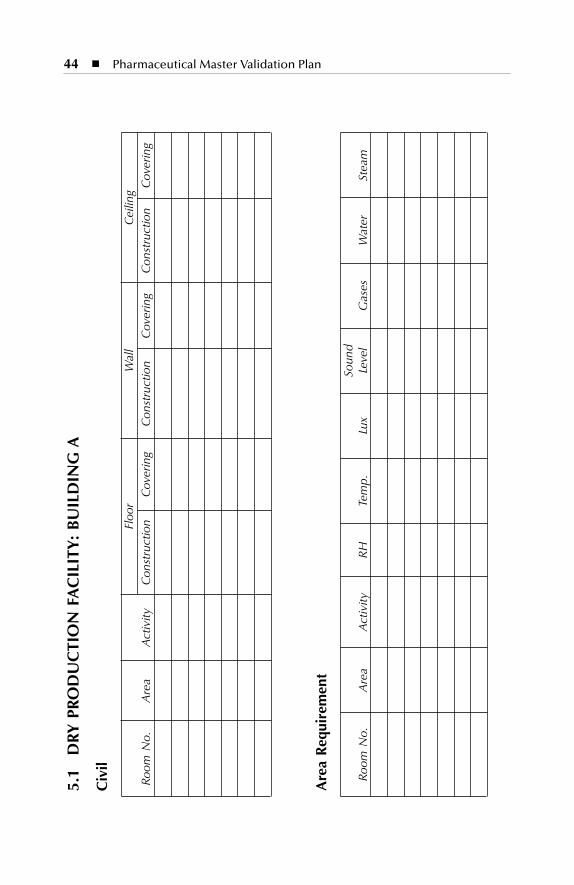
44
�
Pharmaceutical Master Validation Plan
5.1
DRY
PRO
DU
CTI
ON
FA
CIL
ITY
: B
UIL
DIN
G A
Civ
il
Floo
rW
all
Cei
ling
Roo
m N
o.A
rea
Act
ivity
Con
stru
ctio
nC
over
ing
Con
stru
ctio
nC
over
ing
Con
stru
ctio
nC
over
ing
Are
a R
equi
rem
ent
Roo
m N
o.A
rea
Act
ivity
RH
Tem
p.Lu
xSo
und
Leve
lG
ases
Wat
erSt
eam
SL3305_C05_fm Page 44 Thursday, November 8, 2001 3:14 PM
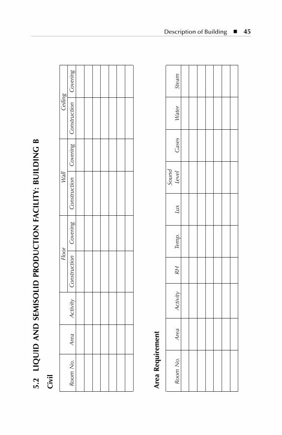
Description of Building
�
45
5.2
LIQ
UID
AN
D S
EMIS
OLI
D P
ROD
UC
TIO
N F
AC
ILIT
Y:
BU
ILD
ING
B
Civ
il
Floo
rW
all
Cei
ling
Roo
m N
o.A
rea
Act
ivity
Con
stru
ctio
nC
over
ing
Con
stru
ctio
nC
over
ing
Con
stru
ctio
nC
over
ing
Are
a R
equi
rem
ent
Roo
m N
o.A
rea
Act
ivity
RH
Tem
p.Lu
xSo
und
Leve
lG
ases
Wat
erSt
eam
SL3305_C05_fm Page 45 Thursday, November 8, 2001 3:14 PM
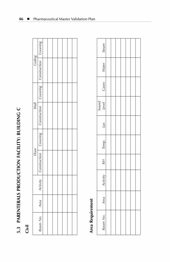
46
�
Pharmaceutical Master Validation Plan
5.3
PAR
ENTE
RALS
PRO
DU
CTI
ON
FA
CIL
ITY
: B
UIL
DIN
G C
Civ
il
Floo
rW
all
Cei
ling
Roo
m N
o.A
rea
Act
ivity
Con
stru
ctio
nC
over
ing
Con
stru
ctio
nC
over
ing
Con
stru
ctio
nC
over
ing
Are
a R
equi
rem
ent
Roo
m N
o.A
rea
Act
ivity
RH
Tem
p.Lu
xSo
und
Leve
lG
ases
Wat
erSt
eam
SL3305_C05_fm Page 46 Thursday, November 8, 2001 3:14 PM
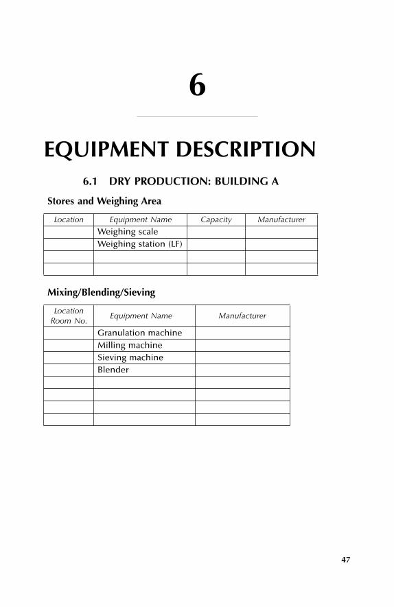
47
6
EQUIPMENT DESCRIPTION
6.1 DRY PRODUCTION: BUILDING A
Stores and Weighing Area
Location Equipment Name Capacity Manufacturer
Weighing scaleWeighing station (LF)
Mixing/Blending/Sieving
LocationRoom No.
Equipment Name Manufacturer
Granulation machineMilling machineSieving machineBlender
SL3305_C06-_fm Page 47 Thursday, November 8, 2001 3:15 PM
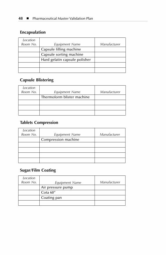
48
�
Pharmaceutical Master Validation Plan
Encapsulation
LocationRoom No. Equipment Name Manufacturer
Capsule filling machineCapsule sorting machineHard gelatin capsule polisher
Capsule Blistering
LocationRoom No. Equipment Name Manufacturer
Thermoform blister machine
Tablets Compression
LocationRoom No. Equipment Name Manufacturer
Compression machine
Sugar/Film Coating
LocationRoom No. Equipment Name Manufacturer
Air pressure pumpCota 60”Coating pan
SL3305_C06-_fm Page 48 Thursday, November 8, 2001 3:15 PM
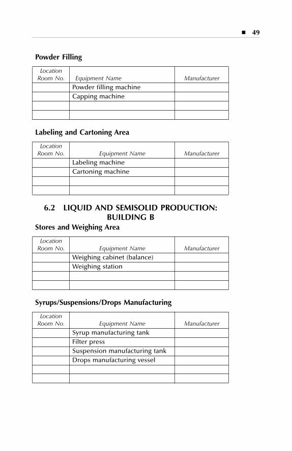
�
49
Powder Filling
LocationRoom No. Equipment Name Manufacturer
Powder filling machineCapping machine
Labeling and Cartoning Area
LocationRoom No. Equipment Name Manufacturer
Labeling machineCartoning machine
6.2 LIQUID AND SEMISOLID PRODUCTION: BUILDING B
Stores and Weighing Area
LocationRoom No. Equipment Name Manufacturer
Weighing cabinet (balance)Weighing station
Syrups/Suspensions/Drops Manufacturing
LocationRoom No. Equipment Name Manufacturer
Syrup manufacturing tankFilter pressSuspension manufacturing tankDrops manufacturing vessel
SL3305_C06-_fm Page 49 Thursday, November 8, 2001 3:15 PM
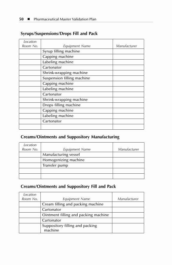
50
�
Pharmaceutical Master Validation Plan
Syrups/Suspensions/Drops Fill and Pack
LocationRoom No. Equipment Name Manufacturer
Syrup filling machineCapping machineLabeling machineCartonatorShrink-wrapping machineSuspension filling machineCapping machineLabeling machineCartonatorShrink-wrapping machineDrops filling machineCapping machineLabeling machine Cartonator
Creams/Ointments and Suppository Manufacturing
LocationRoom No. Equipment Name Manufacturer
Manufacturing vesselHomogenizing machineTransfer pump
Creams/Ointments and Suppository Fill and Pack
LocationRoom No. Equipment Name Manufacturer
Cream filling and packing machineCartonatorOintment filling and packing machineCartonatorSuppository filling and packing
machine
SL3305_C06-_fm Page 50 Thursday, November 8, 2001 3:15 PM
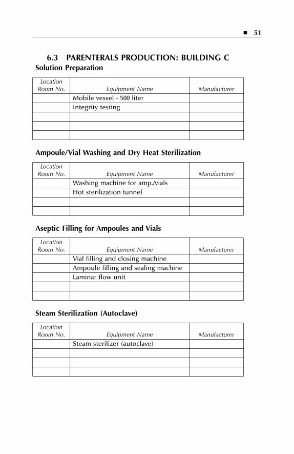
�
51
6.3 PARENTERALS PRODUCTION: BUILDING C
Solution Preparation
LocationRoom No. Equipment Name Manufacturer
Mobile vessel - 500 literIntegrity testing
Ampoule/Vial Washing and Dry Heat Sterilization
LocationRoom No. Equipment Name Manufacturer
Washing machine for amp./vialsHot sterilization tunnel
Aseptic Filling for Ampoules and Vials
LocationRoom No. Equipment Name Manufacturer
Vial filling and closing machineAmpoule filling and sealing machineLaminar flow unit
Steam Sterilization (Autoclave)
LocationRoom No. Equipment Name Manufacturer
Steam sterilizer (autoclave)
SL3305_C06-_fm Page 51 Thursday, November 8, 2001 3:15 PM
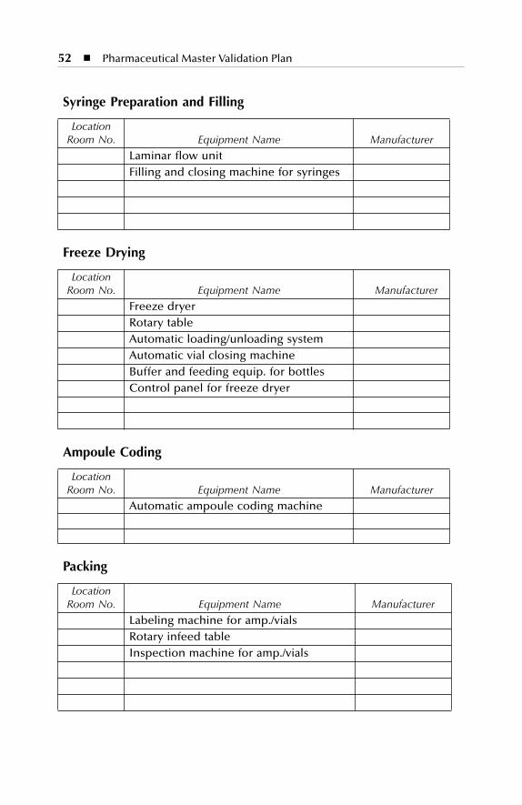
52
�
Pharmaceutical Master Validation Plan
Syringe Preparation and Filling
LocationRoom No. Equipment Name Manufacturer
Laminar flow unitFilling and closing machine for syringes
Freeze Drying
LocationRoom No. Equipment Name Manufacturer
Freeze dryerRotary tableAutomatic loading/unloading systemAutomatic vial closing machineBuffer and feeding equip. for bottlesControl panel for freeze dryer
Ampoule Coding
LocationRoom No. Equipment Name Manufacturer
Automatic ampoule coding machine
Packing
LocationRoom No. Equipment Name Manufacturer
Labeling machine for amp./vials Rotary infeed tableInspection machine for amp./vials
SL3305_C06-_fm Page 52 Thursday, November 8, 2001 3:15 PM
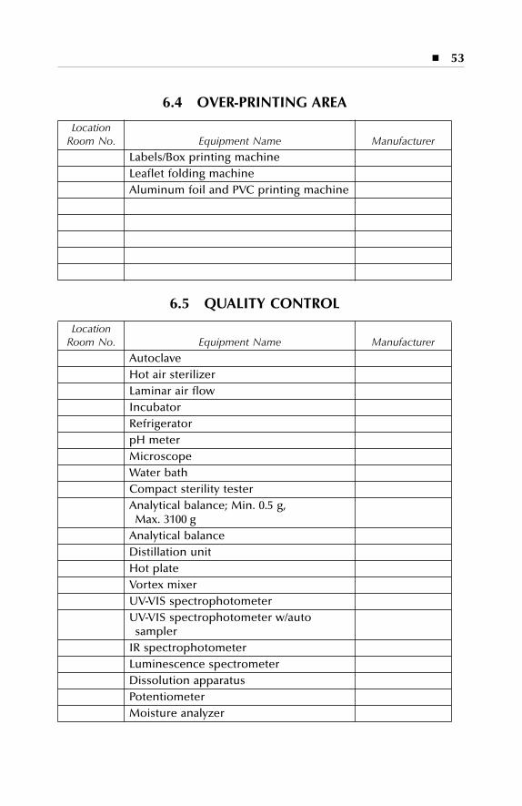
�
53
6.4 OVER-PRINTING AREA
LocationRoom No. Equipment Name Manufacturer
Labels/Box printing machineLeaflet folding machineAluminum foil and PVC printing machine
6.5 QUALITY CONTROL
LocationRoom No. Equipment Name Manufacturer
AutoclaveHot air sterilizerLaminar air flowIncubatorRefrigeratorpH meterMicroscopeWater bathCompact sterility testerAnalytical balance; Min. 0.5 g,
Max. 3100 gAnalytical balanceDistillation unitHot plateVortex mixerUV-VIS spectrophotometerUV-VIS spectrophotometer w/auto
samplerIR spectrophotometer Luminescence spectrometerDissolution apparatusPotentiometerMoisture analyzer
SL3305_C06-_fm Page 53 Thursday, November 8, 2001 3:15 PM
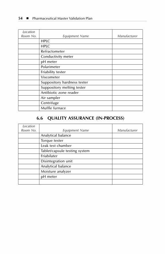
54
�
Pharmaceutical Master Validation Plan
LocationRoom No. Equipment Name Manufacturer
HPLCHPLCRefractometerConductivity meterpH meterPolarimeterFriability testerViscometerSuppository hardness testerSuppository melting testerAntibiotic zone readerAir samplerCentrifugeMuffle furnace
6.6 QUALITY ASSURANCE (IN-PROCESS)
LocationRoom No. Equipment Name Manufacturer
Analytical balanceTorque testerLeak test chamberTablet/capsule testing systemFriabilaterDisintegration unitAnalytical balanceMoisture analyzerpH meter
SL3305_C06-_fm Page 54 Thursday, November 8, 2001 3:15 PM
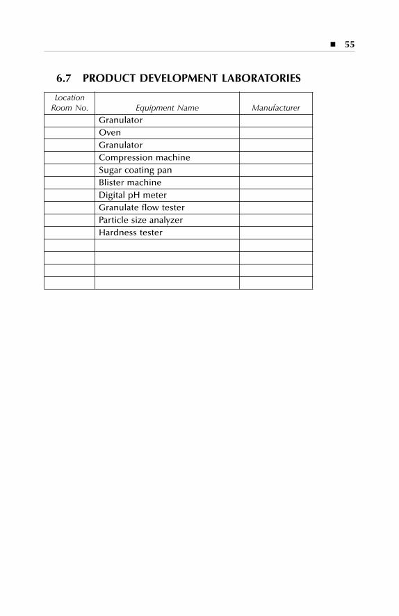
�
55
6.7 PRODUCT DEVELOPMENT LABORATORIES
LocationRoom No. Equipment Name Manufacturer
GranulatorOvenGranulatorCompression machineSugar coating panBlister machineDigital pH meterGranulate flow testerParticle size analyzerHardness tester
SL3305_C06-_fm Page 55 Thursday, November 8, 2001 3:15 PM

SL3305_C06-_fm Page 56 Thursday, November 8, 2001 3:15 PM
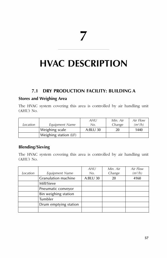
57
7
HVAC DESCRIPTION
7.1 DRY PRODUCTION FACILITY: BUILDING A
Stores and Weighing Area
The HVAC system covering this area is controlled by air handling unit(AHU) No.
Blending/Sieving
The HVAC system covering this area is controlled by air handling unit(AHU) No.
Location Equipment NameAHUNo.
Min. AirChange
Air Flow(m
3
/h)
Weighing scale A:BLU 30 20 1440Weighing station (LF)
Location Equipment NameAHUNo.
Min. AirChange
Air Flow (m
3
/h)
Granulation machine A:BLU 30 20 4160Mill/SievePneumatic conveyorBin weighing stationTumblerDrum emptying station
SL3305_C07_fm Page 57 Thursday, November 8, 2001 3:16 PM
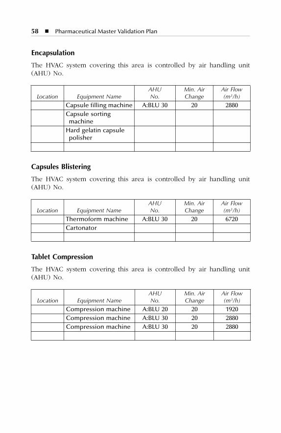
58
�
Pharmaceutical Master Validation Plan
Encapsulation
The HVAC system covering this area is controlled by air handling unit(AHU) No.
Capsules Blistering
The HVAC system covering this area is controlled by air handling unit(AHU) No.
Tablet Compression
The HVAC system covering this area is controlled by air handling unit(AHU) No.
Location Equipment NameAHUNo.
Min. AirChange
Air Flow (m
3
/h)
Capsule filling machine A:BLU 30 20 2880Capsule sorting
machineHard gelatin capsule
polisher
Location Equipment NameAHUNo.
Min. AirChange
Air Flow (m
3
/h)
Thermoform machine A:BLU 30 20 6720Cartonator
Location Equipment NameAHUNo.
Min. AirChange
Air Flow (m
3
/h)
Compression machine A:BLU 20 20 1920Compression machine A:BLU 30 20 2880Compression machine A:BLU 30 20 2880
SL3305_C07_fm Page 58 Thursday, November 8, 2001 3:16 PM
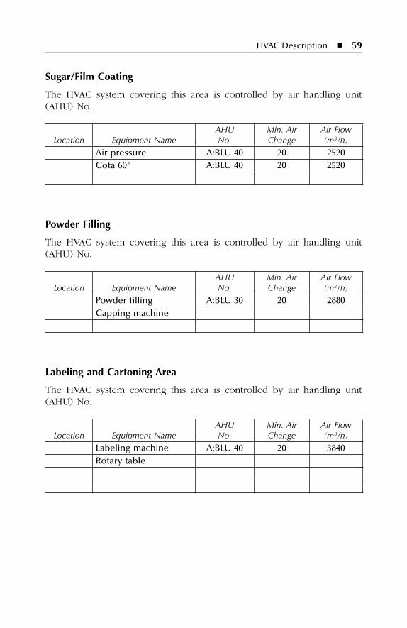
HVAC Description
�
59
Sugar/Film Coating
The HVAC system covering this area is controlled by air handling unit(AHU) No.
Powder Filling
The HVAC system covering this area is controlled by air handling unit(AHU) No.
Labeling and Cartoning Area
The HVAC system covering this area is controlled by air handling unit(AHU) No.
Location Equipment NameAHUNo.
Min. AirChange
Air Flow (m
3
/h)
Air pressure A:BLU 40 20 2520Cota 60" A:BLU 40 20 2520
Location Equipment NameAHUNo.
Min. AirChange
Air Flow (m
3
/h)
Powder filling A:BLU 30 20 2880Capping machine
Location Equipment NameAHUNo.
Min. AirChange
Air Flow (m
3
/h)
Labeling machine A:BLU 40 20 3840Rotary table
SL3305_C07_fm Page 59 Thursday, November 8, 2001 3:16 PM
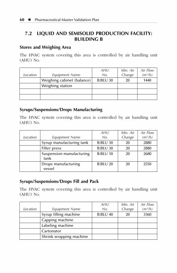
60
�
Pharmaceutical Master Validation Plan
7.2 LIQUID AND SEMISOLID PRODUCTION FACILITY: BUILDING B
Stores and Weighing Area
The HVAC system covering this area is controlled by air handling unit(AHU) No.
Syrups/Suspensions/Drops Manufacturing
The HVAC system covering this area is controlled by air handling unit(AHU) No.
Syrups/Suspensions/Drops Fill and Pack
The HVAC system covering this area is controlled by air handling unit(AHU) No.
Location Equipment NameAHUNo.
Min. AirChange
Air Flow(m
3
/h)
Weighing cabinet (balance) B:BLU 30 20 1440Weighing station
Location Equipment NameAHUNo.
Min. AirChange
Air Flow(m
3
/h)
Syrup manufacturing tank B:BLU 30 20 2880Filter press B:BLU 30 20 2880Suspension manufacturing
tankB:BLU 10 20 2680
Drops manufacturing vessel
B:BLU 20 20 2550
Location Equipment NameAHUNo.
Min. AirChange
Air Flow(m
3
/h)
Syrup filling machine B:BLU 40 20 3360Capping machineLabeling machine CartonatorShrink wrapping machine
SL3305_C07_fm Page 60 Thursday, November 8, 2001 3:16 PM
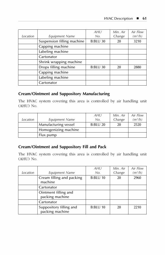
HVAC Description
�
61
Cream/Ointment and Suppository Manufacturing
The HVAC system covering this area is controlled by air handling unit(AHU) No.
Cream/Ointment and Suppository Fill and Pack
The HVAC system covering this area is controlled by air handling unit(AHU) No.
Location Equipment NameAHUNo.
Min. AirChange
Air Flow(m
3
/h)
Suspension filling machine B:BLU 30 20 3210Capping machineLabeling machine CartonatorShrink wrapping machineDrops filling machine B:BLU 30 20 2880Capping machineLabeling machine Cartonator
Location Equipment NameAHUNo.
Min. AirChange
Air Flow(m
3
/h)
Manufacturing vessel B:BLU 20 20 2520Homogenizing machineFlux pump
Location Equipment NameAHUNo.
Min. AirChange
Air Flow(m
3
/h)
Cream filling and packing machine
B:BLU 10 20 2960
CartonatorOintment filling and
packing machineCartonatorSuppository filling and
packing machineB:BLU 10 20 2210
SL3305_C07_fm Page 61 Thursday, November 8, 2001 3:16 PM
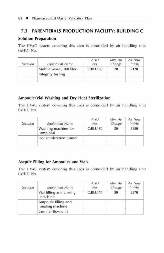
62
�
Pharmaceutical Master Validation Plan
7.3 PARENTERALS PRODUCTION FACILITY: BUILDING C
Solution Preparation
The HVAC system covering this area is controlled by air handling unit(AHU) No.
Ampoule/Vial Washing and Dry Heat Sterilization
The HVAC system covering this area is controlled by air handling unit(AHU) No.
Aseptic Filling for Ampoules and Vials
The HVAC system covering this area is controlled by air handling unit(AHU) No.
Location Equipment NameAHUNo.
Min. AirChange
Air Flow(m
3
/h)
Mobile vessel, 300 liter C:BLU 50 20 2120Integrity testing
Location Equipment NameAHUNo.
Min. AirChange
Air Flow(m
3
/h)
Washing machine for amp./vial
C:BLU 50 20 5880
Hot sterilization tunnel
Location Equipment NameAHUNo.
Min. AirChange
Air Flow(m
3
/h)
Vial filling and closing machine
C:BLU 50 30 2970
Ampoule filling and sealing machine
Laminar flow unit
SL3305_C07_fm Page 62 Thursday, November 8, 2001 3:16 PM
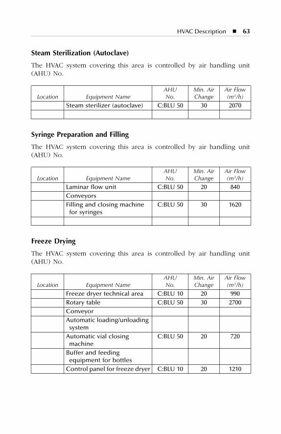
HVAC Description
�
63
Steam Sterilization (Autoclave)
The HVAC system covering this area is controlled by air handling unit(AHU) No.
Syringe Preparation and Filling
The HVAC system covering this area is controlled by air handling unit(AHU) No.
Freeze Drying
The HVAC system covering this area is controlled by air handling unit(AHU) No.
Location Equipment NameAHUNo.
Min. AirChange
Air Flow(m
3
/h)
Steam sterilizer (autoclave) C:BLU 50 30 2070
Location Equipment NameAHUNo.
Min. AirChange
Air Flow(m
3
/h)
Laminar flow unit C:BLU 50 20 840ConveyorsFilling and closing machine
for syringesC:BLU 50 30 1620
Location Equipment NameAHUNo.
Min. AirChange
Air Flow(m
3
/h)
Freeze dryer technical area C:BLU 10 20 990Rotary table C:BLU 50 30 2700ConveyorAutomatic loading/unloading
systemAutomatic vial closing
machine C:BLU 50 20 720
Buffer and feeding equipment for bottles
Control panel for freeze dryer C:BLU 10 20 1210
SL3305_C07_fm Page 63 Thursday, November 8, 2001 3:16 PM
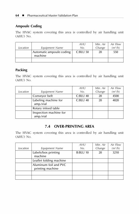
64
�
Pharmaceutical Master Validation Plan
Ampoule Coding
The HVAC system covering this area is controlled by air handling unit(AHU) No.
Packing
The HVAC system covering this area is controlled by air handling unit(AHU) No.
7.4 OVER-PRINTING AREA
The HVAC system covering this area is controlled by air handling unit(AHU) No.
Location Equipment NameAHUNo.
Min. AirChange
Air Flow(m
3
/h)
Automatic ampoule coding machine
C:BLU 50 20 550
Location Equipment NameAHUNo.
Min. AirChange
Air Flow(m
3
/h)
Conveyor belt C:BLU 40 20 4500Labeling machine for
amp./vialC:BLU 40 20 4020
Rotary infeed tableInspection machine for
amp./vial
Location Equipment NameAHUNo.
Min. AirChange
Air Flow(m
3
/h)
Labels/box printing machine
B:BLU 10 20 3210
Leaflet folding machineAluminum foil and PVC
printing machine
SL3305_C07_fm Page 64 Thursday, November 8, 2001 3:16 PM
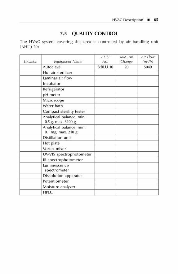
HVAC Description
�
65
7.5 QUALITY CONTROL
The HVAC system covering this area is controlled by air handling unit(AHU) No.
Location Equipment NameAHUNo.
Min. AirChange
Air Flow(m
3
/h)
Autoclave B:BLU 10 20 5040Hot air sterilizerLaminar air flowIncubatorRefrigeratorpH meterMicroscopeWater bathCompact sterility testerAnalytical balance, min.
0.5 g, max. 3100 gAnalytical balance, min.
0.1 mg, max. 210 gDistillation unitHot plateVortex mixerUV-VIS spectrophotometerIR spectrophotometerLuminescence
spectrometerDissolution apparatusPotentiometerMoisture analyzerHPLC
SL3305_C07_fm Page 65 Thursday, November 8, 2001 3:16 PM
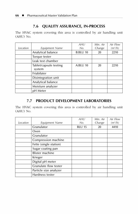
66
�
Pharmaceutical Master Validation Plan
7.6 QUALITY ASSURANCE, IN-PROCESS
The HVAC system covering this area is controlled by air handling unit(AHU) No.
7.7 PRODUCT DEVELOPMENT LABORATORIES
The HVAC system covering this area is controlled by air handling unit(AHU) No.
Location Equipment NameAHUNo.
Min. AirChange
Air Flow(m
3
/h)
Analytical balance B:BLU 10 20 2210Torque testerLeak test chamberTablet/capsule testing
systemA:BLU 10 20 2210
FriabilaterDisintegration unitAnalytical balanceMoisture analyzerpH Meter
Location Equipment NameAHUNo.
Min. AirChange
Air Flow(m
3
/h)
Granulator BLU 15 20 4410OvenGranulatorCompression machineFette (single station)Sugar coating panBlister machineKriegerDigital pH meterGranulate flow testerParticle size analyzerHardness tester
SL3305_C07_fm Page 66 Thursday, November 8, 2001 3:16 PM
67
8
UTILITIES DESCRIPTIONS
The major utilities involved in the routine operation of the plant are asfollows:
8.1 DEIONIZED WATER (DI WATER)
DI water is produced using an XYZ rapid, high-performance, twin-beddeionizer. The plant consists of two glass-reinforced plastic pressurevessels that hold the ion exchange resins together with a process pump,pipe work, valves, flowmeters, and controls to enable the plant to producehigh-quality deionized water and automatically regenerate the resins.
8.2 PURIFIED WATER
The water treatment plant produces Purified Water. The unit that fills the1000-liter storage tank is located in building C first floor from where aloop will start to distribute water in building C. A separate distributionloop starts in building C and allows filling of tanks in buildings A and B.
8.3 WATER FOR INJECTION
The Water for Injection (WFI) is produced by an XYZ multi-effect waterstill (type 300-S), which is intended to produce pure, pyrogen-free distilledwater from pretreated feed water by evaporating and condensing the feedwater (i.e., DI Water). The water still consists of pressure vessels, fivecolumns, and a condenser. The piping between the pressure vessels isstainless steel (S.S.) 316L.
The WFI distribution system (storage tanks, circulation pumps, pipe-work) is steam sterilized. The sterilization cycle is controlled and monitoredby temperature indicators located at critical points.
SL3305_C08_fm Page 67 Thursday, November 8, 2001 3:16 PM
68
�
Pharmaceutical Master Validation Plan
8.4 CHILLED WATER
Two chillers (300-ton capacity each) provide Chilled Water for various airhandling units and all machinery in need of chilled water. Another chiller(15-ton capacity) provides chilled water to boiler, compressor, and deion-ized water plant.
8.5 PURE STEAM
Pure Steam is produced by an XYZ 1500-S pure steam generator. Thegenerator is fed with deionized water that descends the inside tubes whereit is converted into steam. The steam generator is located in building Cfirst floor, from where the loop diverts to different use points; steam trapsare installed to collect condensate when necessary. The quality of puresteam condensate is the same as for Water for Injection.
8.6 COMPRESSED AIR
The plant has two reciprocating oil-free compressors, with a total capacityof 20 m
3
/h. The oil-free Compressed Air is supplied to a stainless steelair receiver. The air then passes through the air filter along with the oiland water separator system and passes through the air dryer and isdistributed through S.S. use points in the three buildings. Terminal sterilefiltration (0.01 µm) is used at critical use points.
8.7 NITROGEN (N
2
)
Nitrogen is supplied by a membrane generator with a capacity of 20 m
3
/hand a minimum purity of 97%. Nitrogen is distributed by an S.S. 316Lpipe network with TIG welding to all required use points. Nitrogen isutilized for the following:
�
Purging during solution preparation
�
Pressurizing process vessels for product transfer and filtration
�
Purging during filling of oxygen-sensitive products
�
Vacuum break during freeze drying
�
Removal of air during filling of liquids
8.8 CARBON DIOXIDE (CO
2
)
Carbon Dioxide is supplied in cylinders and distributed by stores fromthe gas cylinders storage area. Carbon dioxide is utilized during manu-facturing of liquids for blanketing oxygen-sensitive products.
SL3305_C08_fm Page 68 Thursday, November 8, 2001 3:16 PM
Utilities Descriptions
�
69
8.9 ELECTRIC POWER
ABC Pharmaceutical’s total peak power consumption is about 4000 kWh,and is obtained from Water and Electricity Supply Corporation, New York.ABC Pharmaceutical also has three (2) standby generators totalling 4500KVA, which are to be used during main power failure.
8.10 SANITARY WATER
ABC Pharmaceutical’s average water consumption (based on 3 months,i.e., June, July, and August) is about 80,000 gal/day; the water obtainedfrom Water and Electricity Supply Corporation, New York.
The water is stored in an underground tank having a capacity of200,000 gal.
8.11 HVAC (HEATING, VENTILATION, AND AIR-CONDITIONING) SYSTEM
Buildings A, B, and C of ABC Pharmaceutical have a total of 35 AirHandling Units (AHUs). Each building has its own HVAC system withabsolutely separate air handling units.
Building A Dry productionBuilding B Liquids and semisolid productionBuilding C Parenterals production
No contamination is allowed between the three buildings. They arecompletely segregated.
All air handling units (AHUs) are intended to be in continuous oper-ation. The AHU fans are equipped with built-in air flow measuring devicesof the direct-read type (Q-nozzles). This will facilitate monitoring of thedelivered air at remote locations. All exhaust fans are also provided withair flow measuring devices. Some of the parameters will be continuouslymonitored in the critical areas, as shown in the monitoring document.Table 8.1, a monitoring document for buildings A, B, and C, respectively,provides the following information:
Room numberActivityCleanliness classPressure (Pascal)Temperature (°C)Relative humidity (%)Number of air changesAHU number
SL3305_C08_fm Page 69 Thursday, November 8, 2001 3:16 PM
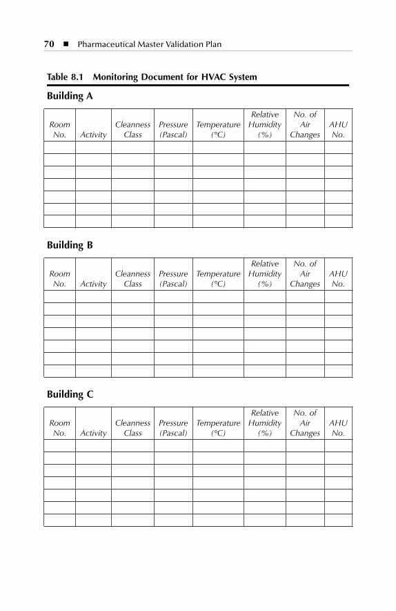
70
�
Pharmaceutical Master Validation Plan
Table 8.1 Monitoring Document for HVAC System
Building A
Room No. Activity
Cleanness Class
Pressure (Pascal)
Temperature (°C)
Relative Humidity
(%)
No. of Air
ChangesAHU No.
Building B
Room No. Activity
Cleanness Class
Pressure (Pascal)
Temperature (°C)
Relative Humidity
(%)
No. of Air
ChangesAHU No.
Building C
Room No. Activity
Cleanness Class
Pressure (Pascal)
Temperature (°C)
Relative Humidity
(%)
No. of Air
ChangesAHU No.
SL3305_C08_fm Page 70 Thursday, November 8, 2001 3:16 PM
71
9
VALIDATION PROGRAM OVERVIEW
9.1 VALIDATION PROJECT MANAGEMENT: ORGANIZATION
SL3305_C09_fm Page 71 Thursday, November 8, 2001 3:17 PM
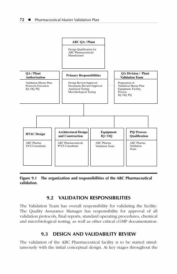
72
�
Pharmaceutical Master Validation Plan
9.2 VALIDATION RESPONSIBILITIES
The Validation Team has overall responsibility for validating the facility.The Quality Assurance Manager has responsibility for approval of allvalidation protocols, final reports, standard operating procedures, chemicaland microbiological testing, as well as other critical cGMP documentation.
9.3 DESIGN AND VALIDABILITY REVIEW
The validation of the ABC Pharmaceutical facility is to be started simul-taneously with the initial conceptual design. At key stages throughout the
Figure 9.1 The organization and responsibilities of the ABC Pharmaceutical validation.
ABC QA / Plant
Design Qualification forABC PharmaceuticalsManufacturer
QA / PlantAuthorization
Primary Responsibilities QA Division / PlantValidation Team
Validation Master Plan Design Review/Approval Preparation ofProtocols Execution Documents Review/Approval Validation Master PlanIQ, OQ, PQ Analytical Testing Equipment, Facility,
Microbiological Testing ProcessIQ, OQ, PQ
HVAC DesignArchitectural Designand Construction
EquipmentIQ / OQ
PQ/ ProcessQualification
ABC Pharma. ABC Pharmaceuticals ABC Pharma. ABC Pharma.XYZ Consultants WYZ Consultants Validation Team Validation
Team
SL3305_C09_fm Page 72 Thursday, November 8, 2001 3:17 PM

Validation Program Overview
�
73
design process, design review meetings are to be held to review andmake key cGMP design decisions.
Through these design review meetings, cGMP and functionality require-ments have and continue to be determined for each aspect of the facility,including:
�
Architectural layout
�
Civil work execution
�
HVAC and cleanroom
�
Water for Injection/Purified water
�
Steam
�
Oil-free compressed air
�
Personnel and material flow
�
Mechanical equipment
�
Material receipt, storage, and shipping
�
Quality Assurance/Control testing and inspection
�
Drainage system
�
Process equipment design
�
Maintenance and calibration access
�
Emergency power
�
Safety engineering
�
Waste disposal
Class Equipment and Systems
1. Class I Equipment and Systems: systems representing processes,equipment, and areas with the highest degree of product qualityand regulatory impact. For example:a. Product/commodity sterilization and depyrogenationb. Utilities utilized during manufacturing (e.g., distilled/deionized
water facilities, compressed air, etc.)c. HVAC system
2. Class II Equipment and Systems: systems representing processes,equipment, and areas with a high degree of product quality andimpact, but which are established processes generally recognizedas prevalent throughout the drug industry. For example:a. Equipment used in product processing (e.g., manufacturing
tanks, mixers, blenders, dryers, etc.)b. Product fill/seal machinesc. Commodity washersd. Granulators.
SL3305_C09_fm Page 73 Thursday, November 8, 2001 3:17 PM
74
�
Pharmaceutical Master Validation Plan
3. Class III Equipment and Systems: systems representing processes,equipment, and areas with a low regulatory and product impact.For example:a. Cap assemblers, cleaners, and washersb. Drying equipmentc. Incubators
9.4 VALIDATION DOCUMENTS
Enhanced Turn-Over Package (ETOP)
The Enhanced Turn-Over Package (ETOP) consists of documentationbinders or files that contain all relative design, installation, and testingdocumentation generated during the design and construction of a partic-ular engineered system such as HVAC or Pure Steam. ETOPs serve tocapture all engineering documentation generated throughout the designconstruction process.
This information is compiled into single-source packages, which thenprovide the foundation for Installation and Operational Qualification.
The Enhanced Turn-Over Package (ETOP) for each system containsall information relating to the following areas:
�
General
�
Equipment
�
Piping
�
Instrumentation
�
Controls and automation
�
Electrical
�
Operating procedures
�
Maintenance procedures and schedules
�
Calibration procedures and schedules
�
Calibration specifications (accuracy requirements)
An Enhanced Turn-Over Package (ETOP) is prepared for each of thefollowing systems:
�
Water for Injection (WFI) system
�
Pure steam
�
Plant steam
�
Drainage and waste decontamination system
�
Compressed gas system
�
Electrical system
SL3305_C09_fm Page 74 Thursday, November 8, 2001 3:17 PM

Validation Program Overview
�
75
�
Building automation system
�
HVAC system
�
Civil work execution
Certification Package Requirements
The following table summarizes the documentation package requirementsfor each equipment system classification.
9.5 INSTALLATION QUALIFICATION PROTOCOLS
The Installation Qualification (IQ) verifies that the equipment or systemand/or corresponding utilities are installed in accordance with designspecifications, manufacturer recommendations, and cGMPs. In addition,the IQ will confirm that critical instruments are calibrated and that systemcomponents are properly identified. Any exceptions will be documented,corrected, and/or justified.
Where possible and applicable, pre-shipment inspection of equipmentand documentation is included as part of the Installation Qualification.
Pre-shipment inspection can be performed along with vendor audits toaddress issues such as software development and quality assurance plans,operational reports, and specific vendor/purchaser inspection reports.
Typical Installation Qualification test functions include, but are notlimited to, the following:
�
Manufacturer specifications
�
Purchase order specifications
�
Piping and installation drawing (P&ID)
�
Construction and installation
�
Test equipment calibration
�
Required spare parts
�
Cleaning/passivation
�
Weld inspection
�
System installation compliance to cGMPs
Equipment Class Certification Package Requirements
a
Class I IQ, OQ, and PQClass II IQ and PQ
a
IQ = Installation Qualification; OQ = Operational Qual-ification; PQ = Performance Qualification
SL3305_C09_fm Page 75 Thursday, November 8, 2001 3:17 PM
76
�
Pharmaceutical Master Validation Plan
The IQ is performed in accordance with a preapproved written pro-tocol. The specific IQ attributes to be verified during the performance ofthe IQ protocol will be developed from system and component designcriteria, cGMP requirements, and other specifying documentation. They,along with the acceptance criteria, will be approved as part of the protocolapproval process.
9.6 OPERATIONAL QUALIFICATION PROTOCOLS
The Operational Qualification (OQ) verifies that the system or equipmentoperates in accordance with design specifications, manufacturer recom-mendations, and cGMPs. OQ testing is designed to simulate the full rangeof operating conditions to establish a system capabilities baseline and toensure that the system operates as intended.
Operational Qualification test functions include, but are not limited to,the following:
�
General operational and control verification
�
Functional testing of computer-related systems
�
Specific operational testing (generation of baseline data)
�
Utility system capability
�
Calibration of test equipment
�
Standard operating procedures (SOPs)
�
Maintenance procedures
�
Cleaning or sanitizing procedures
For equipment or systems controlled or monitored by a computer-related system, the functional testing cycle approach to computer valida-tion is included and performed as part of the Operational Qualification.Functional testing verifies that the integrated hardware and software pro-gram perform in accordance with the functional specifications developedduring the requirements phase.
The Operational Qualification is performed in accordance with apreapproved written protocol. The specific Operational Qualificationattributes to be verified during the performance protocol will bedeveloped from the design specifications, manufacturer documentation,cGMP requirements, and other specific documentation. They, alongwith the acceptance criteria, will be approved as part of the protocolapproval process.
SL3305_C09_fm Page 76 Thursday, November 8, 2001 3:17 PM
Validation Program Overview
�
77
9.7 CHANGE CONTROL INITIATION
Each system/equipment/process will be covered by the EngineeringChange Control program immediately following the completion of the OQtest functions. Any change(s) made to the system during OQ must bedocumented in the Final Report. Any engineering changes proposed afterOQ (i.e., during cycle development, performance qualification, or manu-facturing) must be preapproved and follow the Engineering Change Con-trol procedure.
If changes are made prior to approval of the Final Report, the ChangeControl documentation must be included in the Validation Packages, andthe change and its justification must be documented in the Final Report.
9.8 CYCLE DEVELOPMENT
Critical processes other than the actual product manufacturing process —such as sterilization, component washing, and equipment cleaning — requireprevalidation cycle development work. This may include establishment ofappropriate sterilization cycle types, cleaning agents, etc. This test workis performed during or after Operational Qualification.
Cycle Development does not have to be performed per a writtenprocedure; however, the procedure and results of all work must berecorded in laboratory notebooks, performed in accordance with cGMPdocumentation practices and sound scientific methods, and retained aspart of the Validation Package. At the completion of Cycle Developmentwork, a brief Cycle Development Report will be prepared that identifiesparameters having a high probability of successfully meeting the Perfor-mance Qualification requirements.
9.9 PERFORMANCE QUALIFICATION PROTOCOLS
Performance Qualification (PQ) verifies the performance of critical utilitysystems or processes. Critical utility systems such as WFI and Pure Steamare challenged throughout proposed operating ranges for extended peri-ods of time, while an extensive program of quality monitoring is per-formed. Critical processes such as sterilization of components ar echallenged three (3) consecutive times under worst-case conditions.
Performance Qualification is carried out in accordance with apreapproved written protocol. The specific PQ attributes to be verifiedduring the performance of the protocol will be developed from the finishedproduct specifications, research and development data, cGMP require-ments, and other specific documentation. They, along with the acceptancecriteria, will be approved as part of the protocol approval process.
SL3305_C09_fm Page 77 Thursday, November 8, 2001 3:17 PM
78
�
Pharmaceutical Master Validation Plan
9.10 PROCESS VALIDATION PROTOCOLS
Process Validation (PV) verifies the performance of the overall productmanufacturing process. PV is performed on the entire product manufac-turing process, which includes all support, processes, preparation ofmedia, components, buffers, formulation, filtration, filling, and packaging.
During Process Validation, three (3) consecutive batches are manufac-tured, and all in-process and finished product specifications are verifiedat much higher than normal inspection quantities and frequencies. Criticalparameters are set at different ranges during the manufacturing processto verify that the product consistently meets its predetermined qualityspecification over the range of critical parameter settings. Consequently,a proven acceptable range for each critical parameter is developed.
All equipment, processes, and quality assurance test procedures mustbe validated (or verified if using a compendial method) prior to the startof Process Validation.
Process Validation is performed in accordance with a preapprovedwritten protocol. The specific PV attributes and process parameters to beverified during the performance of the protocol will be developed fromthe finished product specifications, research and development data, themanufacturing process capability, cGMP requirements, and other specificdocumentation. These, along with the acceptance criteria, will be approvedas part of the protocol approval process.
9.11 VALIDATION FINAL REPORTS
The Final Report summarizes the results of the validation process andprovides an analysis of the test data in support of the conclusion that theequipment or system demonstrates consistent performance within theestablished acceptance criteria. Deviations and/or exceptions to approvedprotocols, along with suitable explanations and justifications, are alsodocumented in the Final Report.
9.12 VALIDATION PACKAGE
The Final Report, completed protocols, and all supporting documenta-tion are then gathered into a Final Report Package for review, approval,and retention.
SL3305_C09_fm Page 78 Thursday, November 8, 2001 3:17 PM
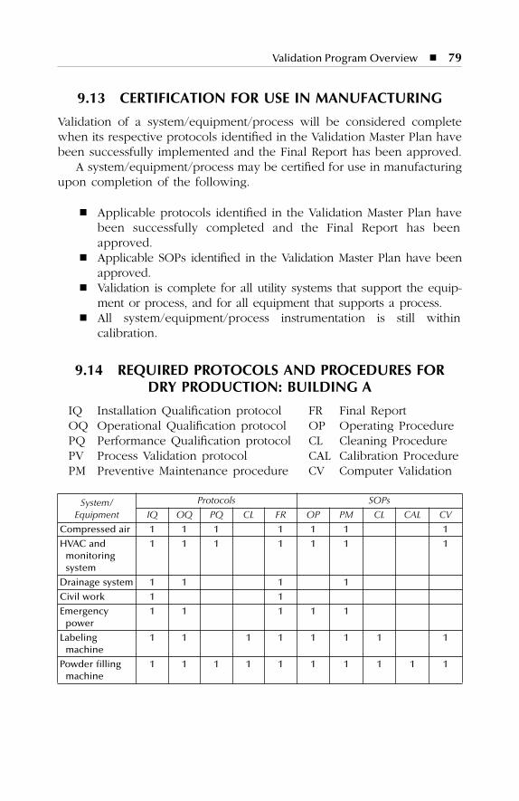
Validation Program Overview
�
79
9.13 CERTIFICATION FOR USE IN MANUFACTURING
Validation of a system/equipment/process will be considered completewhen its respective protocols identified in the Validation Master Plan havebeen successfully implemented and the Final Report has been approved.
A system/equipment/process may be certified for use in manufacturingupon completion of the following.
�
Applicable protocols identified in the Validation Master Plan havebeen successfully completed and the Final Report has beenapproved.
�
Applicable SOPs identified in the Validation Master Plan have beenapproved.
�
Validation is complete for all utility systems that support the equip-ment or process, and for all equipment that supports a process.
�
All system/equipment/process instrumentation is still withincalibration.
9.14 REQUIRED PROTOCOLS AND PROCEDURES FOR DRY PRODUCTION: BUILDING A
IQ Installation Qualification protocol FR Final ReportOQ Operational Qualification protocol OP Operating ProcedurePQ Performance Qualification protocol CL Cleaning ProcedurePV Process Validation protocol CAL Calibration ProcedurePM Preventive Maintenance procedure CV Computer Validation
System/ Equipment
Protocols SOPs
IQ OQ PQ CL FR OP PM CL CAL CV
Compressed air 1 1 1 1 1 1 1
HVAC and monitoring system
1 1 1 1 1 1 1
Drainage system 1 1 1 1
Civil work 1 1
Emergency power
1 1 1 1 1
Labeling machine
1 1 1 1 1 1 1 1
Powder filling machine
1 1 1 1 1 1 1 1 1 1
SL3305_C09_fm Page 79 Thursday, November 8, 2001 3:17 PM
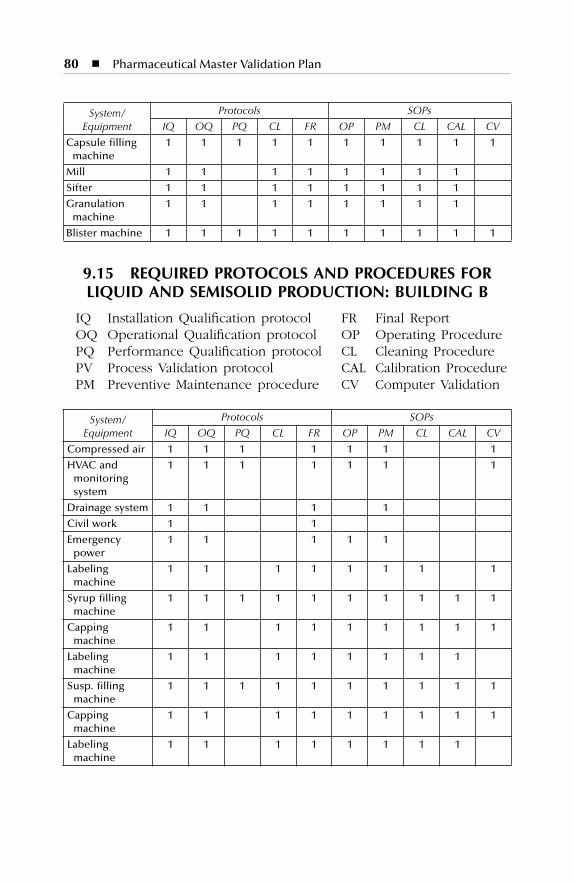
80 � Pharmaceutical Master Validation Plan
9.15 REQUIRED PROTOCOLS AND PROCEDURES FOR LIQUID AND SEMISOLID PRODUCTION: BUILDING B
IQ Installation Qualification protocol FR Final ReportOQ Operational Qualification protocol OP Operating ProcedurePQ Performance Qualification protocol CL Cleaning ProcedurePV Process Validation protocol CAL Calibration ProcedurePM Preventive Maintenance procedure CV Computer Validation
System/ Equipment
Protocols SOPs
IQ OQ PQ CL FR OP PM CL CAL CV
Capsule filling machine
1 1 1 1 1 1 1 1 1 1
Mill 1 1 1 1 1 1 1 1
Sifter 1 1 1 1 1 1 1 1
Granulation machine
1 1 1 1 1 1 1 1
Blister machine 1 1 1 1 1 1 1 1 1 1
System/ Equipment
Protocols SOPs
IQ OQ PQ CL FR OP PM CL CAL CV
Compressed air 1 1 1 1 1 1 1
HVAC and monitoring system
1 1 1 1 1 1 1
Drainage system 1 1 1 1
Civil work 1 1
Emergency power
1 1 1 1 1
Labeling machine
1 1 1 1 1 1 1 1
Syrup filling machine
1 1 1 1 1 1 1 1 1 1
Capping machine
1 1 1 1 1 1 1 1 1
Labeling machine
1 1 1 1 1 1 1 1
Susp. filling machine
1 1 1 1 1 1 1 1 1 1
Capping machine
1 1 1 1 1 1 1 1 1
Labeling machine
1 1 1 1 1 1 1 1
SL3305_C09_fm Page 80 Thursday, November 8, 2001 3:17 PM
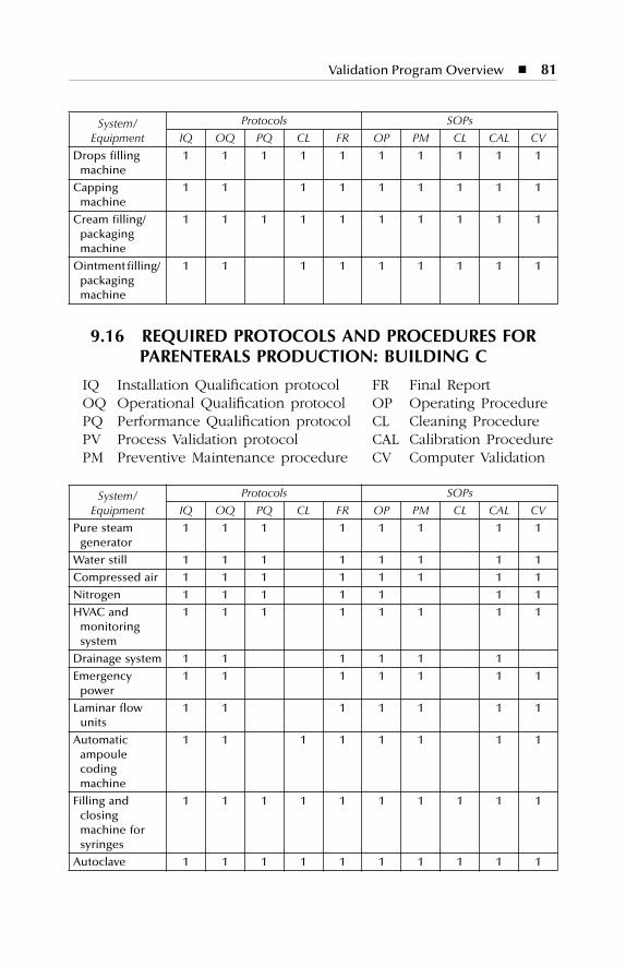
Validation Program Overview � 81
9.16 REQUIRED PROTOCOLS AND PROCEDURES FOR PARENTERALS PRODUCTION: BUILDING C
IQ Installation Qualification protocol FR Final ReportOQ Operational Qualification protocol OP Operating ProcedurePQ Performance Qualification protocol CL Cleaning ProcedurePV Process Validation protocol CAL Calibration ProcedurePM Preventive Maintenance procedure CV Computer Validation
System/ Equipment
Protocols SOPs
IQ OQ PQ CL FR OP PM CL CAL CV
Drops filling machine
1 1 1 1 1 1 1 1 1 1
Capping machine
1 1 1 1 1 1 1 1 1
Cream filling/ packaging machine
1 1 1 1 1 1 1 1 1 1
Ointment filling/ packaging machine
1 1 1 1 1 1 1 1 1
System/ Equipment
Protocols SOPs
IQ OQ PQ CL FR OP PM CL CAL CV
Pure steam generator
1 1 1 1 1 1 1 1
Water still 1 1 1 1 1 1 1 1
Compressed air 1 1 1 1 1 1 1 1
Nitrogen 1 1 1 1 1 1 1
HVAC and monitoring system
1 1 1 1 1 1 1 1
Drainage system 1 1 1 1 1 1
Emergency power
1 1 1 1 1 1 1
Laminar flow units
1 1 1 1 1 1 1
Automatic ampoule coding machine
1 1 1 1 1 1 1 1
Filling and closing machine for syringes
1 1 1 1 1 1 1 1 1 1
Autoclave 1 1 1 1 1 1 1 1 1 1
SL3305_C09_fm Page 81 Thursday, November 8, 2001 3:17 PM
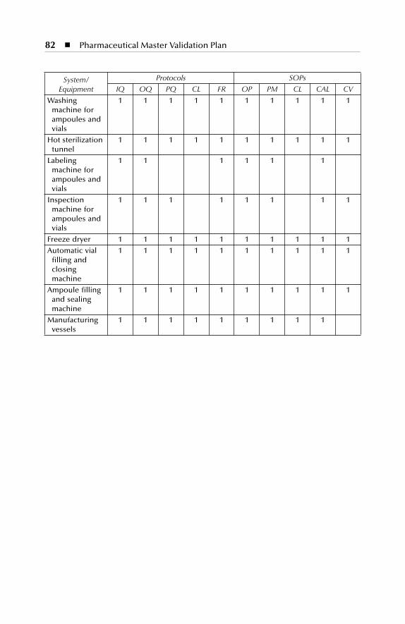
82 � Pharmaceutical Master Validation Plan
System/ Equipment
Protocols SOPs
IQ OQ PQ CL FR OP PM CL CAL CV
Washing machine for ampoules and vials
1 1 1 1 1 1 1 1 1 1
Hot sterilization tunnel
1 1 1 1 1 1 1 1 1 1
Labeling machine for ampoules and vials
1 1 1 1 1 1
Inspection machine for ampoules and vials
1 1 1 1 1 1 1 1
Freeze dryer 1 1 1 1 1 1 1 1 1 1
Automatic vial filling and closing machine
1 1 1 1 1 1 1 1 1 1
Ampoule filling and sealing machine
1 1 1 1 1 1 1 1 1 1
Manufacturing vessels
1 1 1 1 1 1 1 1 1
SL3305_C09_fm Page 82 Thursday, November 8, 2001 3:17 PM
83
10
CALIBRATION PROGRAM SUMMARY
Below is a summary of ABC Pharmaceutical’s Calibration Program, whichis defined in related SOP(s).
1. All process and facility instruments are classified as to their cali-bration status into one of the three following categories:a. Calibrationb. Preventive Maintenancec. No Calibration/No Preventive Maintenance
2. All instruments providing critical process information necessary tomake a quality determination are calibrated with the availablestandards.
3. ABC Pharmaceutical is in the process of procuring calibrationstandards. The Calibration Engineer will be responsible for sched-uling, tracking, and maintenance of standards, records, etc. Allstandards will be traceable to NIST standards.
4. Pre- and post-calibration of instruments utilized in validation studiesare performed to ensure data accuracy.
5. All instruments providing critical process information should becalibrated before performing the validation studies.
SL3305_C10_fm Page 83 Thursday, November 8, 2001 3:18 PM

SL3305_C10_fm Page 84 Thursday, November 8, 2001 3:18 PM
85
11
PREVENTIVE MAINTENANCE PROGRAM SUMMARY
Below is a summary of key points of ABC Pharmaceutical’s PreventiveMaintenance Program, which is defined in related SOP(s).
1. An appropriate Preventive Maintenance Program is defined for theequipment that will be checked at the time of validation.
2. The Supervisor of the related area and the Engineer concernedwill sign the register and verify if repairs are required.
SL3305_C11_fm Page 85 Thursday, November 8, 2001 3:19 PM

SL3305_C11_fm Page 86 Thursday, November 8, 2001 3:19 PM
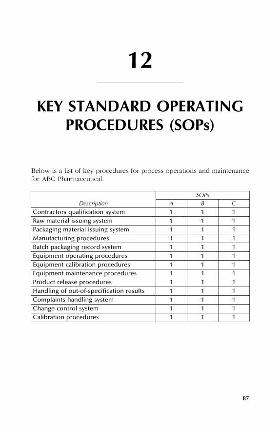
87
12
KEY STANDARD OPERATING PROCEDURES (SOPs)
Below is a list of key procedures for process operations and maintenancefor ABC Pharmaceutical.
DescriptionSOPs
A B C
Contractors qualification system 1 1 1Raw material issuing system 1 1 1Packaging material issuing system 1 1 1Manufacturing procedures 1 1 1Batch packaging record system 1 1 1Equipment operating procedures 1 1 1Equipment calibration procedures 1 1 1Equipment maintenance procedures 1 1 1Product release procedures 1 1 1Handling of out-of-specification results 1 1 1Complaints handling system 1 1 1Change control system 1 1 1Calibration procedures 1 1 1
SL3305_C12_fm Page 87 Thursday, November 8, 2001 3:20 PM

SL3305_C12_fm Page 88 Thursday, November 8, 2001 3:20 PM
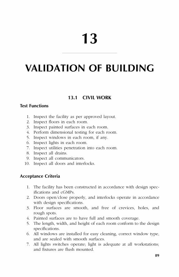
89
13
VALIDATION OF BUILDING
13.1 CIVIL WORK
Test Functions
1. Inspect the facility as per approved layout.2. Inspect floors in each room.3. Inspect painted surfaces in each room.4. Perform dimensional testing for each room.5. Inspect windows in each room, if any.6. Inspect lights in each room.7. Inspect utilities penetration into each room.8. Inspect all drains.9. Inspect all communicators.
10. Inspect all doors and interlocks.
Acceptance Criteria
1. The facility has been constructed in accordance with design spec-ifications and cGMPs.
2. Doors open/close properly, and interlocks operate in accordancewith design specifications.
3. Floor surfaces are smooth, and free of crevices, holes, andrough spots.
4. Painted surfaces are to have full and smooth coverage.5. The length, width, and height of each room conform to the design
specifications.6. All windows are installed for easy cleaning, correct window type,
and are sealed with smooth surfaces.7. All lights switches operate; light is adequate at all workstations;
and fixtures are flush mounted.
SL3305_C13_fm Page 89 Thursday, November 8, 2001 3:20 PM
90
�
Pharmaceutical Master Validation Plan
8. All utilities penetrations are correctly installed, labeled, and sealed.9. All drains are located according to the design specifications.
10. All communicators are correctly installed and sealed.
13.2 DRAINAGE SYSTEM
Test Functions
1. Inspect the drainage system as per the approved layout.2. Inspect floor drain locations as per the approved design.3. Check that process drains are segregated from the sanitary waste.4. Ensure that process drains are provided with deep-seal traps.
Acceptance Criteria
1. The system is constructed and installed in accordance with designspecifications, manufacturer recommendations, and cGMPs.
2. No open floor drains are to be located in Aseptic Core areas:Classes 100, 10,000, and 100,000.
3. Process drains must be separated from sanitary waste drainagesystem.
4. Process drains must have adequate back-flow prevention devices(deep-seal traps) at tie-in to sewer line.
5. Tie-in to sewer line must be located outside immediate building,away from the production area.
SL3305_C13_fm Page 90 Thursday, November 8, 2001 3:20 PM
91
14
VALIDATION OF UTILITY SYSTEMS
This chapter provides a summary of the key validation test functions andacceptance criteria for each utility system. These are provided as a guide-line for those involved in the validation of ABC Pharmaceutical. Approvalof this Master Plan neither provides approval of these test functions andacceptance criteria nor does it limit the test functions and acceptancecriteria included in any protocol. Final approval of test functions andacceptance criteria is made by approval of the Installation, Operational,and where applicable, Performance Qualification protocols.
14.1 PLANT STEAM
Test Functions
1. Perform Installation Qualification of deionizer and distillationequipment, holding tanks, clean steam generator, and distributionsystem.
2. Complete and document all required pre-start-up maintenanceprocedures (including cleaning).
3. Perform general operational controls verification testing.4. Operate system throughout the range of operating design specifi-
cations or range of intended use.5. Confirm that the pressure-reducing regulators in the sub-branches
are set at the predetermined operating pressure ±2 psi.6. Verify that the system has adequate steam capacity during peak
hours of operation. Confirm that the steam pressure is within 5 psiof the recommended operating pressure.
SL3305_C14_fm Page 91 Thursday, November 8, 2001 3:21 PM
92
�
Pharmaceutical Master Validation Plan
7. Record the range of all process or equipment parameters (setpoints, pressure, timing sequences, etc.) verified during operationaland performance qualification testing.
8. Test the water produced by the system to ensure adequateconductivity.
9. Check that the holding tank water quality does not changeadversely during storage in holding tanks.
Acceptance Criteria
1. The system is installed in accordance with design specifications,manufacturer recommendations, and cGMPs. Instruments are cali-brated, identified, and entered into the calibration program.
2. General controls and alarms operate in accordance with designspecifications.
3. The system operates in accordance with design specificationsthroughout the operating range or range of intended use.
4. System regulators must operate within ±2 psi of design levels.5. The system capacity must be sufficient to operate all systems at
peak demand periods.
14.2 PURE STEAM
Test Functions
1. Perform Installation Qualification.2. Perform general operational controls verification testing.3. Operate system throughout range of operating design specifications
or range of intended use.4. Verify that clean steam is fed by a purified water system or WFI
system.5. Confirm that the pressure-reducing regulators in the sub-branches
are set at the predetermined operating pressure ±2 psi.6. Verify that the system has adequate steam capacity during peak
hours of operation. Confirm that the steam pressure is within 5psi of the recommended operating pressure.
7. Operate the system per applicable SOPs. Perform sampling as perthe sampling procedure and schedule. Test steam condensate sam-ples for conformance to current USP Water for Injection monograph(also endotoxin, sterility).
SL3305_C14_fm Page 92 Thursday, November 8, 2001 3:21 PM
Validation of Utility Systems
�
93
8. Record the range of all process or equipment parameters (setpoints, pressure, timing sequences, etc.) verified during Operationaland Performance Qualification testing.
Acceptance Criteria
1. The system is installed in accordance with design specifications,manufacturer recommendations, and cGMPs. Instruments are cali-brated, identified, and entered into the calibration program.
2. General controls and alarms operate in accordance with designspecifications.
3. The system operates in accordance with design specificationsthroughout the operating range or range of intended use.
4. The system capacity must be sufficient to operate all systems atpeak demand periods.
5. Operate the system per applicable SOPs. Perform sampling overa 1-month period as per the sampling procedure and schedule.Test samples for conformance to current USP Water for Injectionmonograph.
6. All samples must meet following criteria:a. Chemical Testing. Test samples must meet the acceptance criteria
of the chemical tests as described in USP 24 Monograph onWater for Injection.
b. Bacteriological Purity. All samples must contain no more than10 cfu/100 ml; no pseudomonas or coliform are detected.
c. Endotoxins. Less than 0.25 EU/ml.
14.3 WATER FOR INJECTION (WFI)
Test Functions
1. Perform Installation Qualification. Verify piping, fittings, properdimensions, drawings, wiring, PC software, calibration, and qualityof materials.
2. Check flow rates, low volume of water supply, excessive pressuredrop, resistivity drops below set point, and temperature drop orincrease beyond set level.
3. Perform general operational controls verification testing.4. Operate system throughout the range of operating design specifi-
cations or range of intended use.5. System regulators must operate within ±2 psi of design level.
SL3305_C14_fm Page 93 Thursday, November 8, 2001 3:21 PM
94
�
Pharmaceutical Master Validation Plan
6. Operate the system per applicable SOPs. Perform sampling overa 1-month period per the sampling procedure and schedule. Testsamples for conformance to current USP Water for Injection mono-graph, microbial content, and endotoxin content. Identify all mor-phologically distinct colony forming units (CFUs) to at least thegenus level.
7. Measure the flow rate and calculate the velocity of the water, ormeasure the velocity directly at a point between the last use pointand the storage tank.
8. Record the range of all process or equipment parameters (setpoints, flow rates, timing sequences, concentrations, etc.) verifiedduring Operational and Performance Qualification testing.
Acceptance Criteria
1. The system is installed in accordance with design specifications,manufacturer recommendations, and cGMPs. Instruments are cali-brated, identified, and entered into the calibration program.
2. General controls and alarms operate in accordance with designspecifications.
3. The system operates in accordance with design specificationsthroughout the operating range or range of intended use.
4. The system flow rate must be in compliance with design specifications.5. All samples must meet the following criteria:
a. Chemical Testing. Test samples must meet the acceptance criteriaof the chemical tests as described in USP 24 Monograph onWater for Injection.
b. Bacteriological Purity. All samples must contain no more than10 cfu/100 ml; no pseudomonas or coliform are detected.
c. Endotoxins. All samples must contain no more than 0.25 EU/ml.d. Physical Properties. The temperature of the hot Water for Injec-
tion must be greater than 80°C.e. Particulate Matter. Small Volume Injection: The Small Volume
Injection meets the requirements of the test if the averagenumber of particles it contains is not more than 10,000 percontainer that are equal to or greater than 10 µm in effectivespherical diameter and not more than 1000 per container equalto or greater than 25 µm in effective spherical diameter.
SL3305_C14_fm Page 94 Thursday, November 8, 2001 3:21 PM
Validation of Utility Systems
�
95
14.4 COMPRESSED AIR
Test Functions
1. Perform Installation Qualification.2. Perform general operational controls verification testing.3. Operate system throughout the range of operating design specifi-
cations or range of intended use.4. Verify that the compressed air system is capable of supplying
pressurized compressed air to all use points. Perform an operationaltest of the distribution system and pressure regulators by monitor-ing the pressure output at the respective use points.
5. Perform a capacity test to verify that the system is capable ofsupplying the required gas, pressure, and flow rate at each use point.
6. Verify that in-line filters are integrity tested. Confirm that all doc-umentation clearly indicates acceptable test results.
7. Perform dew point measurement.8. Perform hydrocarbon content measurement.9. Perform viable particulate count, microbiological at critical use
points after sterile filters (refer to Federal Standard 209E).10. Identification of oxygen content.11. Record the range of all process or equipment parameters (set
points, flow rates, timing sequences, concentrations, etc.) verifiedduring Operational and Performance Qualifications testing.
Acceptance Criteria
1. The system is installed in accordance with design specifications,manufacturer recommendations, and cGMPs. Instruments are cali-brated, identified, and entered into the calibration program.
2. General controls, alarms, and interlocks operate in accordance withdesign specifications.
3. The system operates in accordance with design specificationsthroughout the operating range or range of intended use.
4. The compressed air distribution system must consistently deliverpressurized compressed air to the use points at the design pressureas specified.
5. All in-line filters are integrity tested and qualify per manufacturer’soperating specifications.
6. Dew point must be <0° or lower.
SL3305_C14_fm Page 95 Thursday, November 8, 2001 3:21 PM

96
�
Pharmaceutical Master Validation Plan
7. Hydrocarbon content must be
≤
1 ppm.8. Viable particulate must be
≤
1.0 cfu/10 ft
3
.9. Nonviable particulate counts must be
≤
100/ft
3
of 0.5
µ
or larger atall critical use points.
14.5 NITROGEN (N
2
)
Test Functions
1. Perform Installation Qualification.2. Perform general operational controls verification testing.3. Operate system throughout the range of operating design specifi-
cations or range of intended use.4. Verify that the nitrogen gas system is capable of supplying pres-
surized nitrogen to all use points. Perform an operational test ofthe distribution system and pressure regulators by monitoring thepressure output at the respective use points.
5. Perform a capacity test to verify that the system is capable ofsupplying the required gas, pressure, and flow rate at each use point.
6. Verify that the filters are integrity tested. Confirm that all documen-tation clearly indicates acceptable test results.
7. Perform dew point measurement.8. Perform hydrocarbon content measurement.9. Perform nitrogen gas identification (USP 24 Monograph).
10. Check bioburden if necessary.11. Record the range of all process or equipment parameters (set
points, pressure, timing sequences, etc.) verified during Operationaland Performance Qualifications testing.
Acceptance Criteria
1. The system is installed in accordance with design specifications,manufacturer recommendations, and cGMPs. Instruments are cali-brated, identified, and entered into the calibration program.
2. General controls, alarms, and interlocks operate in accordance withdesign specifications.
3. The system operates in accordance with design specificationsthroughout the operating range or range of intended use.
4. The nitrogen distribution system must consistently deliver pressur-ized nitrogen to the use points at the design pressure specified.
5. All filters are integrity tested and qualified per manufacturer oper-ating specifications.
SL3305_C14_fm Page 96 Thursday, November 8, 2001 3:21 PM
Validation of Utility Systems
�
97
6. Dew point must be –20°C or lower.7. Hydrocarbon level must be
≤
1 ppm.8. Gas quality must conform to the USP 24 Monograph for nitrogen
purity.9. The microbiological test must meet the approved specification
requirements.
14.6 CARBON DIOXIDE (CO
2
)
Test Functions
1. Perform Installation Qualification.2. Perform general operational controls verification testing.3. Operate system throughout the range of operating design specifi-
cations or range of intended use.4. Verify that the carbon dioxide gas system is capable of supplying
pressurized carbon dioxide to all use points. Perform an operationaltest of the distribution system and pressure regulators by monitor-ing the pressure output at the respective use points.
5. Perform a capacity test to verify that the system is capable ofsupplying the required gas, pressure, and flow rate at each use point.
6. Verify that the filters are integrity tested. Confirm that all documen-tation clearly indicates acceptable test results.
7. Perform dew point measurement.8. Perform hydrocarbon content measurement.9. Perform viable particulate count (microbiological particulates).
10. Perform nonviable particulate count.11. Perform CO
2
gas identification (USP 24 Monograph)12. Record the range of all process or equipment parameters (set
points, pressure, timing sequences, etc.) verified during operationaland performance qualifications testing.
Acceptance Criteria
1. The system is installed in accordance with design specifications,manufacturer recommendations, and cGMPs. Instruments are cali-brated, identified, and entered into the calibration program.
2. General controls, alarms, and interlocks operate in accordance withdesign specifications.
3. The system operates in accordance with design specificationsthroughout the operating range or range of intended use.
4. The carbon dioxide distribution system must consistently deliverpressurized carbon dioxide to the use points at the design pressurespecified.
SL3305_C14_fm Page 97 Thursday, November 8, 2001 3:21 PM
98
�
Pharmaceutical Master Validation Plan
5. All filters are integrity tested and qualified per manufacturer’soperating specifications.
6. Dew point must be –20°C or lower.7. Hydrocarbon level must be
≤
1 ppm.8. Viable particulates must be
≤
1.0 cfu per 10 ft
3
.9. Nonviable particulate counts must be
≤
100/ft
3
at 0.5
µ
or larger.10. Gas quality must conform to USP 24 Monograph for carbon dioxide
purity.
14.7 HEATING, VENTILATION, AND AIR CONDITIONING (HVAC)
Test Functions
1. Perform Installation Qualification.2. Perform general operational controls verification testing.3. Operate system throughout the range of operating design specifi-
cations or range of intended use.4. Integrity test all HEPA filters with dioctylphthalate (DOP) smoke
(0.3
µ
).5. Measure the average face velocity of each terminal HEPA filter.
Measure the average velocity 1 ft above the workspace, exposedproduct areas, or exposed component areas in all Class 100 laminarflow rooms or areas.
6. Verify that system air flows have been balanced to within ±10% ofdesign criteria.
7. Verify that directional air flows are consistent with design drawingsby verifying relative differential air pressures.
8. Verify that each room maintains the design temperature range forthree (3) consecutive days.
9. Verify that each room maintains the design relative humidity rangefor three (3) consecutive days.
10. Verify that air flow patterns within Class 100 laminar flow areasare nonturbulent and unidirectional by performing smoke-stick airflow studies and recording the test on videotape.
11. Verify that rooms identified with particulate classifications are cer-tified per Federal Standard 209E for their respective classification(Class 100, 10,000, and 100,000).
12. Verify that AHUs, fans, and heat exchangers operate per designratings.
13. Record the range of all process or equipment parameters (setpoints, flow rates, timing sequences, etc.) verified during opera-tional and performance qualifications testing.
SL3305_C14_fm Page 98 Thursday, November 8, 2001 3:21 PM
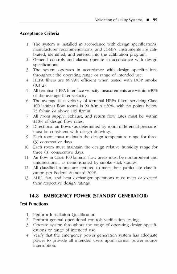
Validation of Utility Systems
�
99
Acceptance Criteria
1. The system is installed in accordance with design specifications,manufacturer recommendations, and cGMPs. Instruments are cali-brated, identified, and entered into the calibration program.
2. General controls and alarms operate in accordance with designspecifications.
3. The system operates in accordance with design specificationsthroughout the operating range or range of intended use.
4. HEPA filters are 99.99% efficient when tested with DOP smoke(0.3
µ
).5. All terminal HEPA filter face velocity measurements are within ±30%
of the average filter velocity.6. The average face velocity of terminal HEPA filters servicing Class
100 laminar flow rooms is 90 ft/min ±20%, with no points below75 ft/min or above 105 ft/min.
7. All room supply, exhaust, and return flow rates must be within±10% of design flow rates.
8. Directional air flows (as determined by room differential pressure)must be consistent with design drawings.
9. Each room must maintain the design temperature range for three(3) consecutive days.
10. Each room must maintain the design relative humidity range forthree (3) consecutive days.
11. Air flow in Class 100 laminar flow areas must be nonturbulent andunidirectional, as demonstrated by smoke-stick studies.
12. All classified rooms are certified to meet their particulate classifi-cation per Federal Standard 209E.
13. AHU, fan, and heat exchanger operations must meet or exceedtheir respective design ratings.
14.8 EMERGENCY POWER (STANDBY GENERATOR)
Test Functions
1. Perform Installation Qualification.2. Perform general operational controls verification testing.3. Operate system throughout the range of operating design specifi-
cations or range of intended use.4. Verify that the emergency power generation system has adequate
power to provide all intended users upon normal power sourceinterruption.
SL3305_C14_fm Page 99 Thursday, November 8, 2001 3:21 PM
100
�
Pharmaceutical Master Validation Plan
5. Record the range of all process or equipment parameters (setpoints, etc.) verified during operational and performance qualifi-cations testing.
Acceptance Criteria
1. The system is installed in accordance with design specifications,manufacturer recommendations, and cGMPs. Instruments are cali-brated, identified, and entered into the calibration program.
2. General controls and alarms operate in accordance with designspecifications.
3. The system operates in accordance with design specificationsthroughout the operating range or range of intended use.
4. All intended users must operate under normal power source inter-ruption conditions.
SL3305_C14_fm Page 100 Thursday, November 8, 2001 3:21 PM
101
15
PROCESS DESCRIPTION FOR DRY PRODUCTION FACILITY:
BUILDING A
SL3305_C15_fm Page 101 Thursday, November 8, 2001 3:22 PM
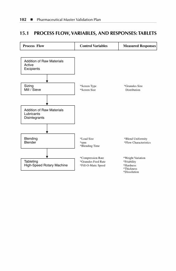
102
�
Pharmaceutical Master Validation Plan
15.1 PROCESS FLOW, VARIABLES, AND RESPONSES: TABLETS
Process Flow Control Variables Measured Responses
Addition of Raw MaterialsActiveExcipients
Sizing *Screen Type *Granules SizeMill / Sieve *Screen Size Distribution
Addition of Raw MaterialsLubricantsDisintegrants
Blending *Load Size *Blend UniformityBlender *rpm *Flow Characteristics
*Blending Time
*Compression Rate *Weight VariationTableting *Granules Feed Rate *FriabilityHigh-Speed Rotary Machine *Fill-O-Matic Speed *Hardness
*Thickness*Dissolution
SL3305_C15_fm Page 102 Thursday, November 8, 2001 3:22 PM
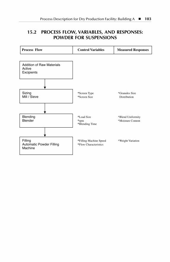
Process Description for Dry Production Facility: Building A
�
103
15.2 PROCESS FLOW, VARIABLES, AND RESPONSES: POWDER FOR SUSPENSIONS
Process Flow Control Variables Measured Responses
Addition of Raw MaterialsActiveExcipients
Sizing *Screen Type *Granules SizeMill / Sieve *Screen Size Distribution
Blending *Load Size *Blend UniformityBlender *rpm *Moisture Content
*Blending Time
Filling *Filling Machine Speed *Weight VariationAutomatic Powder Filling *Flow CharacteristicsMachine
SL3305_C15_fm Page 103 Thursday, November 8, 2001 3:22 PM

104
�
Pharmaceutical Master Validation Plan
15.3 PROCESS FLOW, VARIABLES, AND RESPONSES: CAPSULES
Process Flow Control Variables Measured Responses
Addition of Raw MaterialsActiveExcipients
Mixing * Load Size * Mixing UniformityMixer * rpm
* Mixing Time
Addition of Raw MaterialsLubricantsDisintegrants
Blending *Load Size *Blend UniformityBlender *rpm *Flow Characteristics
*Blending Time
Capsulating *Capsulation Speed *Weight VariationHigh-Speed Capsulation *Powder Feed Rate *Disintegration TimeMachine *Locking
SL3305_C15_fm Page 104 Thursday, November 8, 2001 3:22 PM
105
16
PROCESS DESCRIPTION FOR LIQUID AND SEMISOLID PRODUCTION FACILITY:
BUILDING B
SL3305_C16_fm Page 105 Thursday, November 8, 2001 3:23 PM
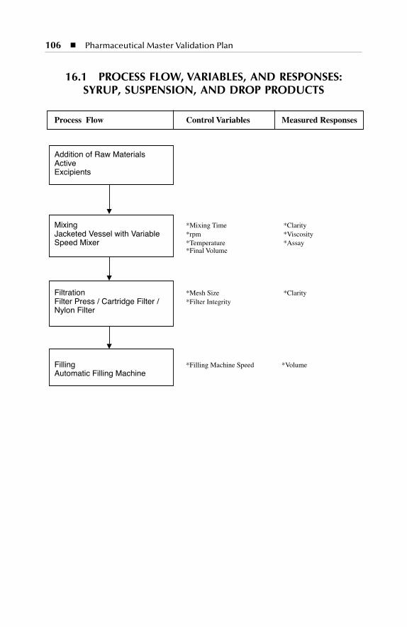
106
�
Pharmaceutical Master Validation Plan
16.1 PROCESS FLOW, VARIABLES, AND RESPONSES: SYRUP, SUSPENSION, AND DROP PRODUCTS
Process Flow Control Variables Measured Responses
Addition of Raw MaterialsActiveExcipients
Mixing *Mixing Time *ClarityJacketed Vessel with Variable *rpm *ViscositySpeed Mixer *Temperature *Assay
*Final Volume
Filtration *Mesh Size *ClarityFilter Press / Cartridge Filter / *Filter IntegrityNylon Filter
Filling *Filling Machine Speed *VolumeAutomatic Filling Machine
SL3305_C16_fm Page 106 Thursday, November 8, 2001 3:23 PM

Process Description for Liquid and Semisolid Production Facility: Building B
�
107
16.2 PROCESS FLOW, VARIABLES, AND RESPONSES: CREAM, OINTMENT, AND SUPPOSITORY PRODUCTS
Process Flow Control Variables Measured Responses
Addition of Raw MaterialsActiveExcipients
Mixing *Mixing Time *ClarityJacketed Vessel with Variable *rpm *Viscosity
Speed Mixer *Temperature *Assay*Amount of Stiffening Agent *Final Volume
FillingAutomatic Filling Machine *Filling Machine Speed *Volume Variation
SL3305_C16_fm Page 107 Thursday, November 8, 2001 3:23 PM

SL3305_C16_fm Page 108 Thursday, November 8, 2001 3:23 PM
109
17
PROCESS DESCRIPTION FOR PARENTERALS PRODUCTION
FACILITY: BUILDING C
SL3305_C17_fm Page 109 Thursday, November 8, 2001 3:23 PM
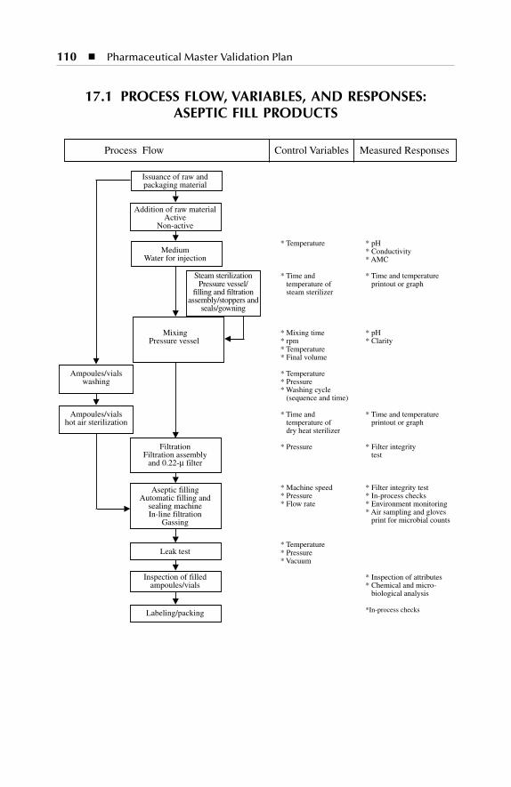
110
�
Pharmaceutical Master Validation Plan
17.1 PROCESS FLOW, VARIABLES, AND RESPONSES: ASEPTIC FILL PRODUCTS
Process Flow Control Variables Measured Responses
Issuance of raw andpackaging material
Addition of raw materialActive
Non-active
* Temperature * pHMedium * Conductivity
Water for injection * AMC
Steam sterilization * Time and * Time and temperaturePressure vessel/ temperature of printout or graph
filling and filtration steam sterilizerassembly/stoppers and
seals/gowning
MixingPressure vessel
* Mixing time * pH* rpm * Clarity* Temperature* Final volume
Ampoules/vials * Temperaturewashing * Pressure
* Washing cycle (sequence and time)
Ampoules/vials * Time and * Time and temperaturehot air sterilization temperature of printout or graph
dry heat sterilizer
Filtration * Pressure * Filter integrity Filtration assembly test
and 0.22-µ filter
Aseptic filling * Machine speed * Filter integrity testAutomatic filling and * Pressure * In-process checks
sealing machine * Flow rate * Environment monitoringIn-line filtration * Air sampling and gloves
Gassing print for microbial counts
* TemperatureLeak test * Pressure
* Vacuum
Inspection of filled * Inspection of attributesampoules/vials * Chemical and micro-
biological analysis
Labeling/packing *In-process checks
SL3305_C17_fm Page 110 Thursday, November 8, 2001 3:23 PM
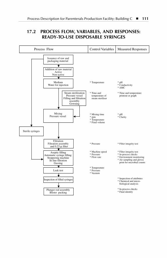
Process Description for Parenterals Production Facility: Building C
�
111
17.2 PROCESS FLOW, VARIABLES, AND RESPONSES: READY-TO-USE DISPOSABLE SYRINGES
Process Flow Control Variables Measured Responses
Issuance of raw andpackaging material
Addition of raw materialActive
Non-active
Medium * Temperature * pHWater for injection * Conductivity
* AMC
Steam sterilization * Time and * Time and temperaturePressure vessel temperature of printout or graph
Filling and filtration steam sterilizerassemblyGowning
MixingPressure vessel
* Mixing time * pH* rpm * Clarity* Temperature* Final volume
Sterile syringes
FiltrationFiltration assembly * Pressure * Filter integrity test
and 0.22-µ filter
Aseptic filling * Machine speed * Filter integrity testAutomatic syringe filling * Pressure * In-process checks
Stoppering machine * Flow rate * Environment monitoringIn-line filtration * Air sampling and gloves
Gassing print for microbial counts
* TemperatureLeak test * Pressure
* Vacuum
Inspection of filled syringes * Inspection of attributes* Chemical and micro- biological analysis
Plunger rod assembly * In-process checksBlister packing * Final identity
SL3305_C17_fm Page 111 Thursday, November 8, 2001 3:23 PM
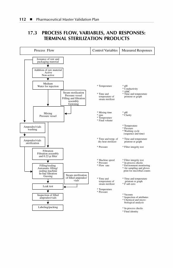
112
�
Pharmaceutical Master Validation Plan
17.3 PROCESS FLOW, VARIABLES, AND RESPONSES: TERMINAL STERILIZATION PRODUCTS
Issuance of raw andpackaging material
Addition of raw material Active
Non-active
Medium* Temperature * pH
* Conductivity* AMC
Water for injection
Steam sterilization * Time and * Time and temperaturePressure vessel temperature of printout or graph
Filling and filtration steam sterilizerassemblyGowning
MixingPressure vessel
* Mixing time * pH* rpm * Clarity* Temperature* Final volume
Ampoules/vials * Temperature
washing * Pressure* Washing cycle (sequence and time)
Ampoules/vials * Time and temp. of * Time and temperature
sterilization dry heat sterilizer printout or graph
Filtration
* Pressure * Filter integrity test
Filtration assemblyand 0.22-µ filter
Filling/sealing
* Machine speed * Filter integrity test
Automatic filling/
* Pressure * In-process checks
sealing machine
* Flow rate * Environment monitoring
In-line filtration
* Air sampling and gloves
Gassing
print for microbial counts
Steam sterilization* Time and * Time and temperatureof filled ampoules/ temperature of printout or graphvials steam sterilizer * F sub-zero
Leak test* Temperature* Pressure
* VacuumInspection of filled* Inspection of attributesampoules/vials* Chemical and micro- biological analysis
Labeling/packing * In-process checks* Final identity
Process Flow Control Variables Measured Responses
SL3305_C17_fm Page 112 Thursday, November 8, 2001 3:23 PM
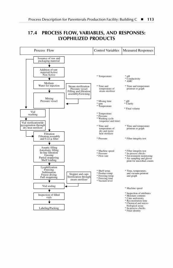
Process Description for Parenterals Production Facility: Building C
�
113
17.4 PROCESS FLOW, VARIABLES, AND RESPONSES: LYOPHILIZED PRODUCTS
Issuance of raw andpackaging material
Addition of raw material/Active
Non Active
Medium
* Temperature * pH
Water for injection
* Conductivity * AMC
Steam sterilization * Time and * Time and temperaturePressure vessel temperature of printout or graph
Filling and filtration steam sterilizerassembly/Gowning
MixingPressure vessel * Mixing time * pH
* rpm * Clarity* Temperature
* Final volumeVial
* Temperaturewashing* Pressure* Washing cycle (sequence and time)
Vial sterilization/de-
Stopper and caps
* Time and * Time and temperaturepyrogenation through
Sterilization through
temperature of printout or graphdry heat sterilizer
steam sterilizer
dry and moist heat sterilizer Filtration
* Pressure * Filter integrity test Filtration assembly
and 0.22-µ filter
Aseptic filling* Machine speed * Filter integrity testAutomatic filling* Pressure * In-process checksIn-line filtration* Flow rate * Environment monitoringGassing
* Air sampling and glovesPartial stoppering print for microbial countsShelf loading
Lyophilization* Shelf temp. * Time, temperature,Freezing* Product temp. and vacuum printoutSublimation* Freezing temp. and graphFreeze drying* Freezing timeFull stoppering* Vacuum level
Vial sealing * Machine speed
* Inspection of attributesInspection of filled * Moisture contents
vials * Cake uniformity * Reconstitution time * Chemical and micro- biological assay
Labeling/Packing * In-process checks * Final identity
Process Flow Control Variables Measured Responses
SL3305_C17_fm Page 113 Thursday, November 8, 2001 3:23 PM

SL3305_C17_fm Page 114 Thursday, November 8, 2001 3:23 PM

115
18
QUALIFICATION OF PROCESS EQUIPMENT
18.1 COMMUTING MILL
Test Functions
1. Perform Installation Qualification. Verify equipment identification,required documents, utilities, manual, and drawings.
2. Perform general operational controls verification testing. Verifycalibration requirements.
3. Operate system throughout the range of operating design specifi-cations or range of intended use. Verify switches and push-buttons,motor speed, empty and loaded mill, rotor blade arrow directions,auger speed arrow direction, rotor blade rotation speeds, and augerfeed speed.
4. Verify that all safety devices are operating as specified in themanual.
5. Verify that recommended lubricants are used during machineoperation.
6. Verify that all lubricants such as oil and grease are kept in clean,sealed containers so that no dust or moisture penetrates and theoxidizing effect of the air is minimal.
7. Perform controller security challenges to verify that specified param-eters cannot be altered without appropriate supervisory control.
8. Perform the particle size test to check the fineness of each productas per product specification.
SL3305_C18_fm Page 115 Thursday, November 8, 2001 3:24 PM
116
�
Pharmaceutical Master Validation Plan
Acceptance Criteria
1. The system is installed in accordance with design specifications,manufacturer recommendations, and cGMPs. Instruments are cali-brated, identified, and entered into the calibration program.
2. General alarms and controls operate in accordance with designspecifications.
3. The system operates in accordance with design specificationsthroughout the operating range or range of intended use.
4. The safety devices operate as specified in the manual.5. The quality of lubricants is adequate, and their storage is dry and
cool.6. Unauthorized changes to cycle parameters must not be allowed
without supervisory control or password.7. The particle size of the mill granules should meet specifications.
18.2 DRYER
Test Functions
1. Perform Installation Qualification. Verify equipment identification,required documents, utilities, manual, and drawings.
2. Perform general operational controls verification testing. Verifycalibration requirements.
3. Operate system throughout the range of operating design specifi-cations or range of intended use. Verify switches and push-buttons,open-door leaks, differential pressure, timer operations, circulationair flow, exhaust air flow, high-temperature limit, and oven-dooropening.
4. Verify that all safety devices of oven drying are operating asspecified in the manual.
5. Verify that recommended lubricants are used during machineoperation.
6. Perform controller security challenges to verify that specifiedparameters cannot be altered without appropriate supervisorycontrol.
7. Perform studies to check the moisture removal on each productas per SOP.
8. Perform the study for establishing the drying time as per acceptablemoisture level.
SL3305_C18_fm Page 116 Thursday, November 8, 2001 3:24 PM
Qualification of Process Equipment
�
117
Acceptance Criteria
1. The system is installed in accordance with design specifications,manufacturer recommendations, and cGMPs. Instruments are cali-brated, identified, and entered into the calibration program.
2. General alarms and controls operate in accordance with designspecifications.
3. The system operates in accordance with design specificationsthroughout the operating range or range of intended use.
4. The safety devices operate as specified in the manual.5. The quality of lubricants is adequate, and their storage is dry and
cool.6. Unauthorized changes to cycle parameters must not be allowed
without supervisory control or password.7. The moisture level should meet specifications.
18.3 V-SHELL BLENDER
Test Functions
1. Perform Installation Qualification. Verify equipment identification,required documents, utilities, manual, and drawings.
2. Verify components material.3. Verify equipment safety features.4. Operate the blender throughout the range of operating design
specifications or range of intended use.5. Verify equipment switches, push-buttons, rotation direction, and
motor fixed speed.6. Perform the assay to check the content uniformity on blended
granules at different locations.
Acceptance Criteria
1. The system is installed in accordance with design specifications,manufacturer recommendations, and cGMPs. Instruments are cali-brated, identified, and entered into the calibration program.
2. General alarms and controls operate in accordance with designspecifications.
3. The system operates in accordance with design specificationsthroughout the operating range or range of intended use.
4. The safety devices operate as specified in the manual.
SL3305_C18_fm Page 117 Thursday, November 8, 2001 3:24 PM
118
�
Pharmaceutical Master Validation Plan
5. The quality of lubricants is adequate and the lubricants are properlystored.
6. Unauthorized changes to cycle parameters are not allowed withoutsupervisory control or password.
7. Assay results should be within the specifications.
18.4 TABLET COMPRESSION
Test Functions
1. Perform Installation Qualification.2. Perform general operational controls verification testing.3. Operate system throughout the range of operating design specifi-
cations or range of intended use.4. Verify that all safety devices of the tablet press are operating as
specified in the manual.5. Verify that recommended lubricants are used during machine
operation.6. Perform controller security challenges to verify that specified param-
eters cannot be altered without appropriate supervisory control.7. Perform capability and consistency studies to check the weight
variation of each product as per SOP.
Acceptance Criteria
1. The system is installed in accordance with design specifications,manufacturer recommendations, and cGMPs. Instruments are cali-brated, identified, and entered into the calibration program.
2. General controls and alarms operate in accordance with designspecifications.
3. The system operates in accordance with design specificationsthroughout the operating range or range of intended use.
4. The safety devices must operate as specified in the manual.5. The recommended lubricants must be used as specified in the
manual.6. The storage location of the lubricants must be according to man-
ufacturer recommendations.7. Unauthorized changes to cycle parameters must not be allowed
without supervisory control or password.8. The machine must be in statistical control as per capability and
consistency studies.
SL3305_C18_fm Page 118 Thursday, November 8, 2001 3:24 PM
Qualification of Process Equipment
�
119
18.5 CAPSULATION
Test Functions
1. Perform Installation Qualification.2. Perform general operational controls verification testing.3. Operate system throughout the range of operating design specifi-
cations or range of intended use.4. Verify that all safety devices on the capsulation machine are oper-
ating as specified in the manual.5. Verify that recommended lubricants are used during machine
operation.6. Verify that all lubricants such as oil and grease are kept in clean,
sealed containers so that no dust or moisture penetrates.7. Perform controller security challenges to verify that specified param-
eters cannot be altered without appropriate supervisory control.8. Perform capability and consistency studies to check the weight
variation of each product as per SOP.
Acceptance Criteria
1. The system is installed in accordance with design specifications,manufacturer recommendations, and cGMPs. Instruments are cali-brated, identified, and entered into the calibration program.
2. General controls and alarms operate in accordance with designspecifications.
3. The system operates in accordance with design specificationsthroughout the operating range or range of intended use.
4. The safety devices must operate as specified in the manual.5. The recommended lubricants must be used as specified in the
manual.6. The storage location of the lubricants must be according to man-
ufacturer recommendations.7. Unauthorized changes to cycle parameters must not be allowed
without supervisory control or password.8. Machine must be in statistical control as per capability and con-
sistency studies.
18.6 POWDER FILLING
Test Functions
1. Perform Installation Qualification.
SL3305_C18_fm Page 119 Thursday, November 8, 2001 3:24 PM
120
�
Pharmaceutical Master Validation Plan
2. Perform general operational controls verification testing.3. Operate system throughout the range of operating design specifi-
cations or range of intended use.4. Verify that all safety devices of the powder filling machine are
operating as specified in the manual.5. Verify that recommended lubricants are used during machine
operation.6. Verify that all lubricants such as oil and grease are kept in clean,
sealed containers so that no dust or moisture penetrates.7. Perform controller security challenges to verify that specified param-
eters cannot be altered without appropriate supervisory control.8. Perform capability and consistency studies to check the weight
variation of each product as per SOP.
Acceptance Criteria
1. The system is installed in accordance with design specifications,manufacturer recommendations, and cGMPs. Instruments are cali-brated, identified, and entered into the calibration program.
2. General controls and alarms operate in accordance with designspecifications.
3. The system operates in accordance with design specificationsthroughout the operating range or range of intended use.
4. Safety devices must operate as specified in the manual.5. The recommended lubricants must be used as specified in the
manual.6. The storage location of the lubricants must be according to the
manufacturer recommendations.7. Unauthorized changes to cycle parameters must not be allowed
without supervisory control or password.8. Machine must be in statistical control as per capability and con-
sistency studies.
18.7 CAPSULE POLISHER
Test Functions
1. Perform Installation Qualification.2. Perform general operational controls verification testing.3. Operate system throughout the range of operating design specifi-
cations or range of intended use.
SL3305_C18_fm Page 120 Thursday, November 8, 2001 3:24 PM
Qualification of Process Equipment
�
121
4. Verify that all safety devices of the capsule polisher are operatingas specified in the manual.
5. Verify that recommended lubricants are used during machineoperation.
6. Verify that all lubricants such as oil and grease are kept in clean,sealed containers so that no dust or moisture penetrates.
7. Perform controller security challenges to verify that specified param-eters cannot be altered without appropriate supervisory control.
8. Perform studies to check the capsule polishing of each product asper SOP.
Acceptance Criteria
1. The system is installed in accordance with design specifications,manufacturer recommendations, and cGMPs. Instruments are cali-brated, identified, and entered into the calibration program.
2. General alarms and controls operate in accordance with designspecifications.
3. The system operates in accordance with design specificationsthroughout the operating range or range of intended use.
4. Safety devices operate as specified in the manual.5. The quality of lubricants is adequate and as per supplier’s
recommendation.6. Unauthorized changes to cycle parameters must not be allowed
without supervisory control or password.7. The machine must be in statistical control as per study.
18.8 TABLET COATING
Test Functions
1. Perform Installation Qualification. Verify equipment identification,required documents, utilities, component materials, drawings, andmanuals.
2. Perform general operational controls verification testing. Verify coat-ing pan motor, supply blower, exhaust motor, and spray system.
3. Operate system throughout the range of operating design specifi-cations or range of intended use. Verify switches and push-buttons,rotator direction, motor variable speed, supply temperature, differ-ential pressure, and pan air flow.
4. Verify that all safety devices are operating as specified in themanual.
SL3305_C18_fm Page 121 Thursday, November 8, 2001 3:24 PM
122
�
Pharmaceutical Master Validation Plan
5. Verify that recommended lubricants are used during machineoperation.
6. Verify that all lubricants such as oil and grease are kept in clean,sealed containers so that no dust or moisture penetrates.
7. Perform controller security challenges to verify that specified param-eters cannot be altered without appropriate supervisory control.
8. Perform physical attribute characteristic studies to check the uni-formity of the coating on each product as per SOP and acceptancecriteria.
Acceptance Criteria
1. The system is installed in accordance with design specifications,manufacturer recommendations, and cGMPs. Instruments are cali-brated, identified, and entered into the calibration program.
2. General alarms and controls operate in accordance with designspecifications.
3. The system operates in accordance with design specificationsthroughout the operating range or range of intended use.
4. Safety devices operate as specified in the manual.5. The quality of lubricants is adequate and their storage as recom-
mended by the manufacturer.6. Unauthorized changes to cycle parameters must not be allowed
without supervisory control or password.7. Coating must be in compliance with SOP and acceptable quality
levels.
18.9 SYRUP MANUFACTURING VESSEL
Test Functions
1. Perform Installation Qualification.2. Perform general operational controls verification testing.3. Operate system throughout the range of operating design specifi-
cations of mixing speed, temperature, and vacuum, or the rangeof intended use.
4. Verify that all safety devices of vessel are operating as specified inthe manual.
5. Verify that recommended lubricants are used during machineoperation.
6. Verify that all lubricants such as oil and grease are kept in clean,sealed containers so that no dust or moisture penetrates.
SL3305_C18_fm Page 122 Thursday, November 8, 2001 3:24 PM
Qualification of Process Equipment
�
123
7. Perform controller security challenges to verify that specified param-eters cannot be altered without appropriate supervisory control.
8. Assay the final mix to check the content uniformity of each productas per SOP.
Acceptance Criteria
1. The system is installed in accordance with design specifications,manufacturer recommendations, and cGMPs. Instruments are cali-brated, identified, and entered into the calibration program.
2. General controls and alarms operate in accordance with designspecifications.
3. The system operates in accordance with design specificationsthroughout the operating range or range of intended use.
4. Safety devices must operate as specified in the manual.5. The recommended lubricants must be used as specified in the
manual.6. The storage location of the lubricants must be according to man-
ufacturer recommendations.7. Unauthorized changes to cycle parameters must not be allowed
without supervisory control or password.8. Assay results should meet specifications.
18.10 SUSPENSION MANUFACTURING VESSEL
Test Functions
1. Perform Installation Qualification.2. Perform general operational controls verification testing.3. Operate system throughout the range of operating design specifi-
cations of mixing speed, temperature, and vacuum and homoge-nization, or the range of intended use.
4. Verify that all safety devices of the vessel are operating as specifiedin the manual.
6. Verify that all lubricants such as oil and grease are kept in clean,sealed containers so that no dust or moisture penetrates.
7. Perform controller security challenges to verify that specified param-eters cannot be altered without appropriate supervisory control.
8. Assay the final mix to check the content uniformity of each productas per SOP.
9. Perform particle size distribution and re-suspendibility tests overthe final blend as per SOP.
SL3305_C18_fm Page 123 Thursday, November 8, 2001 3:24 PM
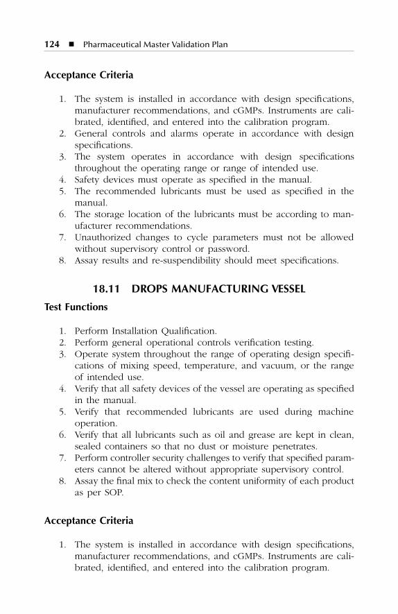
124
�
Pharmaceutical Master Validation Plan
Acceptance Criteria
1. The system is installed in accordance with design specifications,manufacturer recommendations, and cGMPs. Instruments are cali-brated, identified, and entered into the calibration program.
2. General controls and alarms operate in accordance with designspecifications.
3. The system operates in accordance with design specificationsthroughout the operating range or range of intended use.
4. Safety devices must operate as specified in the manual.5. The recommended lubricants must be used as specified in the
manual.6. The storage location of the lubricants must be according to man-
ufacturer recommendations.7. Unauthorized changes to cycle parameters must not be allowed
without supervisory control or password.8. Assay results and re-suspendibility should meet specifications.
18.11 DROPS MANUFACTURING VESSEL
Test Functions
1. Perform Installation Qualification.2. Perform general operational controls verification testing.3. Operate system throughout the range of operating design specifi-
cations of mixing speed, temperature, and vacuum, or the rangeof intended use.
4. Verify that all safety devices of the vessel are operating as specifiedin the manual.
5. Verify that recommended lubricants are used during machineoperation.
6. Verify that all lubricants such as oil and grease are kept in clean,sealed containers so that no dust or moisture penetrates.
7. Perform controller security challenges to verify that specified param-eters cannot be altered without appropriate supervisory control.
8. Assay the final mix to check the content uniformity of each productas per SOP.
Acceptance Criteria
1. The system is installed in accordance with design specifications,manufacturer recommendations, and cGMPs. Instruments are cali-brated, identified, and entered into the calibration program.
SL3305_C18_fm Page 124 Thursday, November 8, 2001 3:24 PM

Qualification of Process Equipment
�
125
2. General controls and alarms operate in accordance with designspecifications.
3. The system operates in accordance with design specificationsthroughout the operating range or range of intended use.
4. The safety devices must operate as specified in the manual.5. The recommended lubricants must be used as specified in the
manual.6. The storage location of the lubricants must be according to man-
ufacturer recommendations.7. Unauthorized changes to cycle parameters must not be allowed
without supervisory control or password.8. Assay results should meet specifications.
18.12 MIXER
Test Functions
1. Perform Installation Qualification.2. Perform general operational controls verification testing.3. Operate system throughout the range of mixing speed or range of
intended use.4. Verify that all safety devices of the mixer are operating as specified
in the manual.5. Verify that recommended lubricants are used during machine
operation.6. Verify that all lubricants such as oil and grease are kept in clean,
sealed containers so that no dust or moisture penetrates.7. Perform controller security challenges to verify that specified param-
eters cannot be altered without appropriate supervisory control.8. Assay the mixed blend to check the content uniformity of each
product as per SOP.
Acceptance Criteria
1. The system is installed in accordance with design specifications,manufacturer recommendations, and cGMPs. Instruments are cali-brated, identified, and entered into the calibration program.
2. General controls and alarms operate in accordance with designspecifications.
3. The system operates in accordance with design specificationsthroughout the operating range or range of intended use.
4. Safety devices must operate as specified in the manual.
SL3305_C18_fm Page 125 Thursday, November 8, 2001 3:24 PM
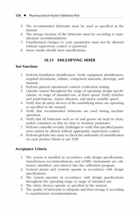
126
�
Pharmaceutical Master Validation Plan
5. The recommended lubricants must be used as specified in themanual.
6. The storage location of the lubricants must be according to man-ufacturer recommendations.
7. Unauthorized changes to cycle parameters must not be allowedwithout supervisory control or password.
8. Assay results should meet specifications.
18.13 EMULSIFYING MIXER
Test Functions
1. Perform Installation Qualification. Verify equipment identification,required documents, utilities, component materials, drawings, andmanuals.
2. Perform general operational controls verification testing.3. Operate system throughout the range of operating design specifi-
cations, or range of intended use, at fixed speed. Verify switchesand push-buttons, rotator direction, and motor variable speed.
4. Verify that all safety devices of the emulsifying mixer are operatingas specified in the manual.
5. Verify that recommended lubricants are used during machineoperation.
6. Verify that all lubricants such as oil and grease are kept in clean,sealed containers so that no dust or moisture penetrates.
7. Perform controller security challenges to verify that specified param-eters cannot be altered without appropriate supervisory control.
8. Perform globule size assay to check the uniformity of emulsificationon each product blend as per SOP.
Acceptance Criteria
1. The system is installed in accordance with design specifications,manufacturer recommendations, and cGMPs. Instruments are cali-brated, identified, and entered into the calibration program.
2. General alarms and controls operate in accordance with designspecifications.
3. The system operates in accordance with design specificationsthroughout the operating range or range of intended use.
4. The safety devices operate as specified in the manual.5. The quality of lubricants is adequate and their storage is according
to manufacturer recommendations.
SL3305_C18_fm Page 126 Thursday, November 8, 2001 3:24 PM
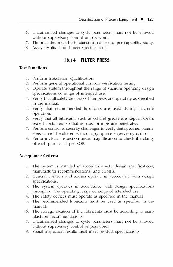
Qualification of Process Equipment
�
127
6. Unauthorized changes to cycle parameters must not be allowedwithout supervisory control or password.
7. The machine must be in statistical control as per capability study.8. Assay results should meet specifications.
18.14 FILTER PRESS
Test Functions
1. Perform Installation Qualification.2. Perform general operational controls verification testing.3. Operate system throughout the range of vacuum operating design
specifications or range of intended use.4. Verify that all safety devices of filter press are operating as specified
in the manual.5. Verify that recommended lubricants are used during machine
operation.6. Verify that all lubricants such as oil and grease are kept in clean,
sealed containers so that no dust or moisture penetrates.7. Perform controller security challenges to verify that specified param-
eters cannot be altered without appropriate supervisory control.8. Perform visual inspection under magnification to check the clarity
of each product as per SOP.
Acceptance Criteria
1. The system is installed in accordance with design specifications,manufacturer recommendations, and cGMPs.
2. General controls and alarms operate in accordance with designspecifications.
3. The system operates in accordance with design specificationsthroughout the operating range or range of intended use.
4. The safety devices must operate as specified in the manual.5. The recommended lubricants must be used as specified in the
manual.6. The storage location of the lubricants must be according to man-
ufacturer recommendations.7. Unauthorized changes to cycle parameters must not be allowed
without supervisory control or password.8. Visual inspection results must meet product specifications.
SL3305_C18_fm Page 127 Thursday, November 8, 2001 3:24 PM
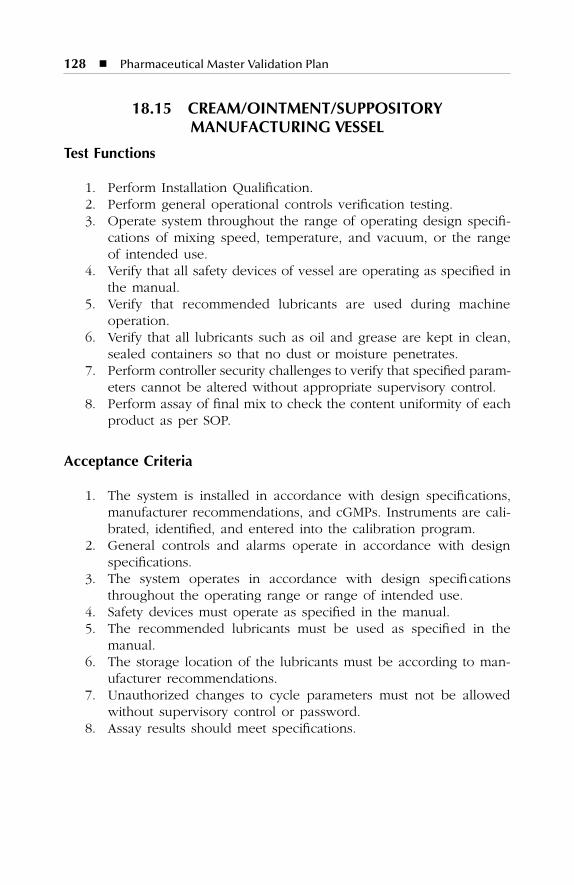
128
�
Pharmaceutical Master Validation Plan
18.15 CREAM/OINTMENT/SUPPOSITORY MANUFACTURING VESSEL
Test Functions
1. Perform Installation Qualification.2. Perform general operational controls verification testing.3. Operate system throughout the range of operating design specifi-
cations of mixing speed, temperature, and vacuum, or the rangeof intended use.
4. Verify that all safety devices of vessel are operating as specified inthe manual.
5. Verify that recommended lubricants are used during machineoperation.
6. Verify that all lubricants such as oil and grease are kept in clean,sealed containers so that no dust or moisture penetrates.
7. Perform controller security challenges to verify that specified param-eters cannot be altered without appropriate supervisory control.
8. Perform assay of final mix to check the content uniformity of eachproduct as per SOP.
Acceptance Criteria
1. The system is installed in accordance with design specifications,manufacturer recommendations, and cGMPs. Instruments are cali-brated, identified, and entered into the calibration program.
2. General controls and alarms operate in accordance with designspecifications.
3. The system operates in accordance with design specificationsthroughout the operating range or range of intended use.
4. Safety devices must operate as specified in the manual.5. The recommended lubricants must be used as specified in the
manual.6. The storage location of the lubricants must be according to man-
ufacturer recommendations.7. Unauthorized changes to cycle parameters must not be allowed
without supervisory control or password.8. Assay results should meet specifications.
SL3305_C18_fm Page 128 Thursday, November 8, 2001 3:24 PM
Qualification of Process Equipment
�
129
18.16 SYRUP, SUSPENSION, AND DROP FILLING MACHINE
Test Functions
1. Perform Installation Qualification.2. Perform general operational controls verification testing.3. Operate system throughout the range of operating design specifi-
cations or range of intended use (e.g., different packages).4. Verify that all safety devices of vessel are operating as specified in
the manual.5. Verify that recommended lubricants are used during machine
operation.6. Verify that all lubricants such as oil and grease are kept in clean,
sealed containers so that no dust or moisture penetrates.7. Perform controller security challenges to verify that specified param-
eters cannot be altered without appropriate supervisory control.8. Perform capability studies to check the volume variation on each
size of product as per SOP.
Acceptance Criteria
1. The system is installed in accordance with design specifications,manufacturer recommendations, and cGMPs. Instruments are cali-brated, identified, and entered into the calibration program.
2. General controls and alarms operate in accordance with designspecifications.
3. The system operates in accordance with design specificationsthroughout the operating range or range of intended use.
4. Safety devices must operate as specified in the manual.5. The recommended lubricants must be used as specified in the
manual.6. The storage location of the lubricants must be according to man-
ufacturer recommendations.7. Unauthorized changes to cycle parameters must not be allowed
without supervisory control or password.8. The machine must be in statistical control as per capability study.
SL3305_C18_fm Page 129 Thursday, November 8, 2001 3:24 PM
130
�
Pharmaceutical Master Validation Plan
18.17 CREAM AND OINTMENT FILLING MACHINE
Test Functions
1. Perform Installation Qualification.2. Perform general operational controls verification testing.3. Operate system throughout the range of operating design specifi-
cations or range of intended use.4. Verify that all safety devices of filling machine are operating as
specified in the manual.5. Verify that recommended lubricants are used during machine
operation.6. Verify that all lubricants such as oil and grease are kept in clean,
sealed containers so that no dust or moisture penetrates.7. Perform controller security challenges to verify that specified param-
eters cannot be altered without appropriate supervisory control.8. Perform capability studies to check the weight variation of each
product as per SOP.
Acceptance Criteria
1. The system is installed in accordance with design specifications,manufacturer recommendations, and cGMPs. Instruments are cali-brated, identified, and entered into the calibration program.
2. General controls and alarms operate in accordance with designspecifications.
3. The system operates in accordance with design specificationsthroughout the operating range or range of intended use.
4. Safety devices must operate as specified in the manual.5. The recommended lubricants must be used as specified in the
manual.6. The storage location of the lubricants must be according to man-
ufacturer recommendations.7. Unauthorized changes to cycle parameters must not be allowed
without supervisory control or password.8. The machine must be in statistical control as per capability study.
18.18 SUPPOSITORY FILLING MACHINE
Test Functions
1. Perform Installation Qualification.2. Perform general operational controls verification testing.
SL3305_C18_fm Page 130 Thursday, November 8, 2001 3:24 PM

Qualification of Process Equipment
�
131
3. Operate system throughout the range of operating design specifi-cations of mixing speed, temperature, fill volume/weight, or therange of intended use.
4. Verify that all safety devices of the suppository filling machine areoperating as specified in the manual.
5. Verify that recommended lubricants are used during machineoperation.
6. Verify that all lubricants such as oil and grease are kept in clean,sealed containers so that no dust or moisture penetrates.
7. Perform controller security challenges to verify that specified param-eters cannot be altered without appropriate supervisory control.
8. Perform capability and consistency studies to check the weightvariation of each product as per SOP.
Acceptance Criteria
1. The system is installed in accordance with design specifications,manufacturer recommendations, and cGMPs. Instruments are cali-brated, identified, and entered into the calibration program.
2. General controls and alarms operate in accordance with designspecifications.
3. The system operates in accordance with design specificationsthroughout the operating range or range of intended use.
4. Safety devices must operate as specified in the manual.5. The recommended lubricants must be used as specified in the
manual.6. The storage location of the lubricants must be as per manufacturer
recommendations.7. Unauthorized changes to cycle parameters must not be allowed
without supervisory control or password.8. Machine must be in statistical control as per capability and con-
sistency studies.
18.19 LABELING MACHINE
Test Functions
1. Perform Installation Qualification.2. Perform general operational controls verification testing.3. Operate system throughout the range of operating design speci-
fications of speed, temperature, and vacuum, or the range ofintended use.
SL3305_C18_fm Page 131 Thursday, November 8, 2001 3:24 PM
132
�
Pharmaceutical Master Validation Plan
4. Verify that all safety devices of labeling machine are operating asspecified in the manual.
5. Perform controller security challenges to verify that specified param-eters cannot be altered without appropriate supervisory control.
6. Perform inspection to check the labeling on each product asper SOP.
Acceptance Criteria
1. The system is installed in accordance with design specifications,manufacturer recommendations, and cGMPs. Instruments are cali-brated, identified, and entered into the calibration program.
2. General controls and alarms operate in accordance with designspecifications.
3. The system operates in accordance with design specificationsthroughout the operating range or range of intended use.
4. The safety devices must operate as specified in the manual.5. Unauthorized changes to cycle parameters must not be allowed
without supervisory control or password.6. The labeling is performed in accordance with the acceptance
criteria.
18.20 CAPPING MACHINE
Test Functions
1. Perform Installation Qualification.2. Perform general operational controls verification testing.3. Operate system throughout the range of operating design specifi-
cations of speed, or the range of intended use.4. Verify that all safety devices of capping machine are operating as
specified in the manual.5. Verify that recommended lubricants are used during machine
operation.6. Verify that all lubricants such as oil and grease are kept in clean,
sealed containers so that no dust or moisture penetrates.7. Perform controller security challenges to verify that specified param-
eters cannot be altered without appropriate supervisory control.8. Perform the torque test on different bottle sizes and check the
capping on each product as per SOP.
SL3305_C18_fm Page 132 Thursday, November 8, 2001 3:24 PM
Qualification of Process Equipment
�
133
Acceptance Criteria
1. The system is installed in accordance with design specifications,manufacturer recommendations, and cGMPs.
2. General controls and alarms operate in accordance with designspecifications.
3. The system operates in accordance with design specificationsthroughout the operating range or range of intended use.
4. Safety devices must operate as specified in the manual.5. The recommended lubricants must be used as specified in the
manual.6. The storage location of the lubricants must be according to man-
ufacturer recommendations.7. Unauthorized changes to cycle parameters must not be allowed
without supervisory control or password.8. Torque of the caps should meet specifications.
18.21 CARTONATOR
Test Functions
1. Perform Installation Qualification.2. Perform general operational controls verification testing.3. Operate system throughout the range of operating design specifi-
cations of feeding speed, or the range of intended use.4. Verify that all safety devices of cartonator are operating as specified
in the manual.5. Perform controller security challenges to verify that specified param-
eters cannot be altered without appropriate supervisory control.6. Check that change parts of each size are available.7. Perform inspection to check the cartoning on each product as
per SOP.
Acceptance Criteria
1. The system is installed in accordance with design specifications,manufacturer recommendations, and cGMPs.
2. General controls and alarms operate in accordance with designspecifications.
3. The system operates in accordance with design specificationsthroughout the operating range or range of intended use.
SL3305_C18_fm Page 133 Thursday, November 8, 2001 3:24 PM

134
�
Pharmaceutical Master Validation Plan
4. Safety devices must operate as specified in the manual.5. Unauthorized changes to cycle parameters must not be allowed
without supervisory control or password.6. The cartoning operation meets the acceptance criteria.
18.22 SHRINK-WRAPPING MACHINE
Test Functions
1. Perform Installation Qualification.2. Perform general operational controls verification testing.3. Operate system throughout the range of operating design specifi-
cations of shrink-wrapping speed, temperature, and vacuum, orthe range of intended use.
4. Verify that all safety devices of the shrink-wrapping machine areoperating as specified in the manual.
5. Perform controller security challenges to verify that specified param-eters cannot be altered without appropriate supervisory control.
6. Perform inspection to check the shrink-wrapping on each productas per SOP.
Acceptance Criteria
1. The system is installed in accordance with design specifications,manufacturer recommendations, and cGMPs.
2. General controls and alarms operate in accordance with designspecifications.
3. The system operates in accordance with design specificationsthroughout the operating range or range of intended use.
4. Safety devices must operate as specified in the manual.5. Unauthorized changes to cycle parameters must not be allowed
without supervisory control or password.6. The shrink-wrapping operation meets the acceptance criteria.
18.23 OVER-PRINTING MACHINE
Test Functions
1. Perform Installation Qualification2. Perform general operational controls verification testing.3. Operate system throughout the range of operating design specifi-
cations of printing speed, or the range of intended use.
SL3305_C18_fm Page 134 Thursday, November 8, 2001 3:24 PM
Qualification of Process Equipment � 135
4. Verify that all safety devices of the over-printing machine areoperating as specified in the manual.
5. Verify that recommended lubricants are used during machineoperation.
6. Perform inspection to check the over-printing on each product asper SOP.
Acceptance Criteria
1. The system is installed in accordance with design specifications,manufacturer recommendations, and cGMPs. Instruments are cali-brated, identified, and entered into the calibration program.
2. General controls and alarms operate in accordance with designspecifications.
3. The system operates in accordance with design specificationsthroughout the operating range or range of intended use.
4. Safety devices must operate as specified in the manual.5. The recommended lubricants must be used as specified in the
manual.6. The over-printing operation meets the acceptance criteria.
18.24 TRAYS AND RACK WASHER
Test Functions
1. Perform Installation Qualification. Verify equipment identification,required documents, utilities, components material, drawings, andmanuals.
2. Perform general operational controls verification testing. Checkheader drive circulation pump, rinse pump, detergent pump,exhaust fan, and drying fan.
3. Operate system throughout the range of operating design specifi-cations or range of intended use at fixed speed. Verify switchesand push-buttons and calibration requirements.
4. Verify that all safety devices of tray/rack washer are operating asspecified in the manual.
5. Verify that recommended lubricants are used during machineoperation.
6. Perform controller security challenges to verify that specified param-eters cannot be altered without appropriate supervisory control.
7. Perform the study to check the time of washing and detergentcontamination on each product as per SOP.
SL3305_C18_fm Page 135 Thursday, November 8, 2001 3:24 PM
136 � Pharmaceutical Master Validation Plan
Acceptance Criteria
1. The system is installed in accordance with design specifications,manufacturer recommendations, and cGMPs. Instruments are cali-brated, identified, and entered into the calibration program.
2. General alarms and controls operate in accordance with designspecifications.
3. The system operates in accordance with design specificationsthroughout the operating range or range of intended use.
4. The safety devices operate as specified in the manual.5. Unauthorized changes to cycle parameters must not be allowed
without supervisory control or password.6. The tray and rack washer operation shall meet the acceptance
criteria.
18.25 AUTOCLAVE (STEAM STERILIZER)
Test Functions
1. Perform Installation Qualification.2. Perform general operational controls verification testing.3. Operate system throughout the range of operating design specifi-
cations or range of intended use.4. Perform vacuum pump evacuation rate test to verify that the
vacuum pump evacuates the chamber at the rate specified.5. Perform chamber vacuum and positive pressure integrity verifica-
tion studies to verify that the chamber does not leak.6. Perform controller security challenges to verify that sterilization
cycle parameters cannot be altered without appropriate supervisorycontrol.
7. Take pressure and temperature measurements to verify that thesteam is 100% saturated during the dwell period.
8. Perform simulated steam supply failures to verify that the controllereither resets the dwell timer or stops incrementing upon a dropin temperature below the set point.
9. Perform three (3) empty chamber heat distribution studies todetermine the thermal characteristics of the sterilization cycles. AKaye Validator equipped with thermocouples shall be used to mapthe internal chamber temperatures.
10. Perform three (3) loaded chamber heat penetration studies todetermine the coolest point within a specified load and configu-ration. A Kaye Validator equipped with thermocouple-probed con-tainers will be used to provide an equal representation amonglayers in the chamber.
SL3305_C18_fm Page 136 Thursday, November 8, 2001 3:24 PM
Qualification of Process Equipment � 137
11. Perform microbiological challenge studies to determine the degreeof process lethality provided by the sterilization cycle. The micro-organisms most frequently utilized to challenge steam sterilizationcycles are Bacillus Stearothermophilus and Clostridium Sporogenesof 106 population.
A Kaye Validator equipped with thermocouple-probed containersand the containers previously inoculated with the biological indi-cator will be positioned in the detected cool points of the loadconfiguration. After the sterilization cycle is complete, the inocu-lated containers are recovered and subjected to microbiologicaltest procedures.
12. Record the range of all process or equipment parameters (setpoints, flow rates, timing sequences, concentrations, etc.) verifiedduring operational and performance qualifications testing.
13. Air filters must be tested for integrity.
Acceptance Criteria
1. The system is installed in accordance with design specifications,manufacturer recommendations, and cGMPs. Instruments are cali-brated, identified, and entered into the calibration program.
2. General controls and alarms operate in accordance with designspecifications.
3. The system operates in accordance with design specificationsthroughout the operating range or range of intended use.
4. The vacuum pump evacuates the chamber to the target pressureat a rate equal to or greater than specified.
5. The average chamber leak rate is in accordance with the manu-facturer recommendations.
6. Unauthorized changes to cycle parameters are not allowed withoutsupervisory control or password.
7. The temperature and pressure during the dwell period must indi-cate 100% saturated steam.
8. The controller must either reset the dwell timer or stop increment-ing upon a drop in temperature below the set point.
9. The chamber temperature recorded by the sterilizer temperaturecontrol system must be within ±0.5°C of the set point during thestabilized portion of the dwell period.
10. The maximum temperature deviation from the mean chambertemperature at any one print interval during the stabilized dwellperiod is within ±0.5°C.
SL3305_C18_fm Page 137 Thursday, November 8, 2001 3:24 PM
138 � Pharmaceutical Master Validation Plan
11. Heat distribution thermocouples at each 1-minute print interval mustbe within ±1.0°C of the mean chamber temperature of all distributionthermocouples during the dwell period after stabilization.
12. The slowest-to-heat location (coolest point) in each test run mustreceive an F0 (121°C) of at least 20 minutes, as calculated duringthe dwell period only.
13. A minimum Solution Microbiological Challenge Spore Log Reduc-tion (SLR) of equal to or greater than 6 must be shown for each run.
14. Air filters must pass integrity test.
18.26 HOT AIR TUNNEL (DRY HEAT STERILIZER)
Test Functions
1. Perform Installation Qualification.2. Perform general operational controls verification testing.3. Operate system throughout the range of operating design specifi-
cations or range of intended use.4. Document the system operation, including performance checks of
safety interlocks and values of operating parameters, during aminimum of three (3) consecutive acceptable runs.
5. Verify that particulate levels within the chamber are within accept-able limits.
6. Perform three (3) empty chamber heat distribution studies todetermine the thermal characteristics of the sterilization cycles. AKaye Validator equipped with thermocouples should be used tomap the internal chamber temperatures.
7. Perform three (3) loaded chamber heat penetration studies to verifythat the temperature distribution is uniform for the load configu-ration, and that all measured points within each load configurationreceive thermal treatment sufficient for depyrogenation and steril-ization. A Kaye Validator equipped with thermocouple-probedcontainers shall be used to provide an equal representation amonglayers in the chamber.
8. Perform microbiological challenge test. Confirm through laboratorytesting that all endotoxin samples in each load are reduced by aminimum of 3 logs. Endotoxin reduction of 3 logs or greater willalso ensure a greater than 12 log reduction of biological organisms.
9. Record the range of all process or equipment parameters (setpoints, flow rates, timing sequences, concentrations, etc.) verifiedduring Operational and Performance Qualifications testing.
SL3305_C18_fm Page 138 Thursday, November 8, 2001 3:24 PM
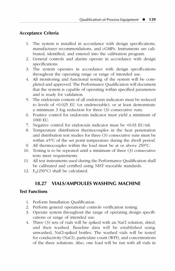
Qualification of Process Equipment � 139
Acceptance Criteria
1. The system is installed in accordance with design specifications,manufacturer recommendations, and cGMPs. Instruments are cali-brated, identified, and entered into the calibration program.
2. General controls and alarms operate in accordance with designspecifications.
3. The system operates in accordance with design specificationsthroughout the operating range or range of intended use.
4. All monitoring and functional testing of the system will be com-pleted and approved. The Performance Qualification will documentthat the system is capable of operating within specified parametersand is ready for validation.
5. The endotoxin content of all endotoxin indicators must be reducedto levels of <0.025 EU (or undetectable), or at least demonstratea minimum 3 log reduction for three (3) consecutive runs.
6. Positive control for endotoxin indicator must yield a minimum of1000 EU.
7. Negative control for endotoxin indicator must be <0.03 EU/ml.8. Temperature distribution thermocouples in the heat penetration
and distribution test studies for three (3) consecutive runs must bewithin ±5°C of the set point temperature during the dwell period.
9. All thermocouples within the load must be at or above 250°C.10. Testing is to be repeated until a minimum of three (3) consecutive
tests meet requirements.11. All test instruments used during the Performance Qualification shall
be calibrated and certified using NIST traceable standards.12. FH(250°C) shall be calculated.
18.27 VIALS/AMPOULES WASHING MACHINE
Test Functions
1. Perform Installation Qualification.2. Perform general operational controls verification testing.3. Operate system throughout the range of operating design specifi-
cations or range of intended use.4. Three (3) sets of vials will be spiked with an NaCl solution, dried,
and then washed. Baseline data will be established usingunwashed, NaCl-spiked bottles. The washed vials will be testedfor conductivity (NaCl), particulate count (WFI), and concentrationsof the three solutions. Also, one load will be run with all vials in
SL3305_C18_fm Page 139 Thursday, November 8, 2001 3:24 PM
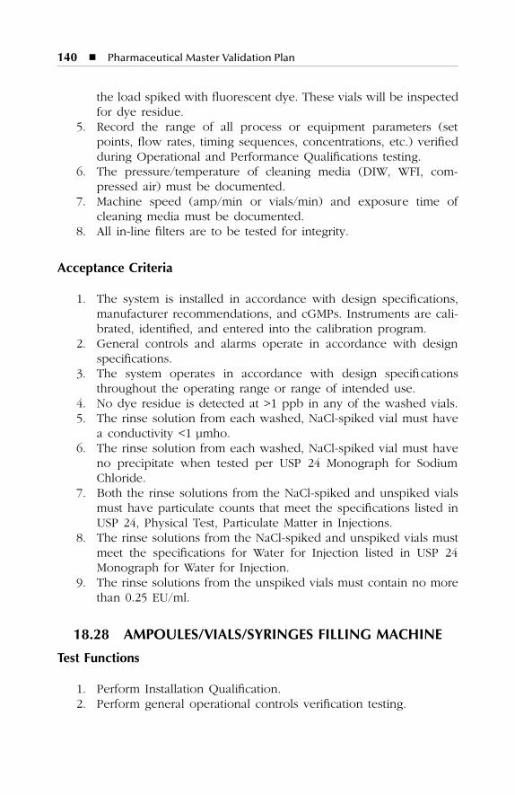
140 � Pharmaceutical Master Validation Plan
the load spiked with fluorescent dye. These vials will be inspectedfor dye residue.
5. Record the range of all process or equipment parameters (setpoints, flow rates, timing sequences, concentrations, etc.) verifiedduring Operational and Performance Qualifications testing.
6. The pressure/temperature of cleaning media (DIW, WFI, com-pressed air) must be documented.
7. Machine speed (amp/min or vials/min) and exposure time ofcleaning media must be documented.
8. All in-line filters are to be tested for integrity.
Acceptance Criteria
1. The system is installed in accordance with design specifications,manufacturer recommendations, and cGMPs. Instruments are cali-brated, identified, and entered into the calibration program.
2. General controls and alarms operate in accordance with designspecifications.
3. The system operates in accordance with design specificationsthroughout the operating range or range of intended use.
4. No dye residue is detected at >1 ppb in any of the washed vials.5. The rinse solution from each washed, NaCl-spiked vial must have
a conductivity <1 µmho.6. The rinse solution from each washed, NaCl-spiked vial must have
no precipitate when tested per USP 24 Monograph for SodiumChloride.
7. Both the rinse solutions from the NaCl-spiked and unspiked vialsmust have particulate counts that meet the specifications listed inUSP 24, Physical Test, Particulate Matter in Injections.
8. The rinse solutions from the NaCl-spiked and unspiked vials mustmeet the specifications for Water for Injection listed in USP 24Monograph for Water for Injection.
9. The rinse solutions from the unspiked vials must contain no morethan 0.25 EU/ml.
18.28 AMPOULES/VIALS/SYRINGES FILLING MACHINE
Test Functions
1. Perform Installation Qualification.2. Perform general operational controls verification testing.
SL3305_C18_fm Page 140 Thursday, November 8, 2001 3:24 PM
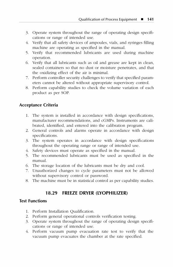
Qualification of Process Equipment � 141
3. Operate system throughout the range of operating design specifi-cations or range of intended use.
4. Verify that all safety devices of ampoules, vials, and syringes fillingmachine are operating as specified in the manual.
5. Verify that recommended lubricants are used during machineoperation.
6. Verify that all lubricants such as oil and grease are kept in clean,sealed containers so that no dust or moisture penetrates, and thatthe oxidizing effect of the air is minimal.
7. Perform controller security challenges to verify that specified param-eters cannot be altered without appropriate supervisory control.
8. Perform capability studies to check the volume variation of eachproduct as per SOP.
Acceptance Criteria
1. The system is installed in accordance with design specifications,manufacturer recommendations, and cGMPs. Instruments are cali-brated, identified, and entered into the calibration program.
2. General controls and alarms operate in accordance with designspecifications.
3. The system operates in accordance with design specificationsthroughout the operating range or range of intended use.
4. Safety devices must operate as specified in the manual.5. The recommended lubricants must be used as specified in the
manual.6. The storage location of the lubricants must be dry and cool.7. Unauthorized changes to cycle parameters must not be allowed
without supervisory control or password.8. The machine must be in statistical control as per capability studies.
18.29 FREEZE DRYER (LYOPHILIZER)
Test Functions
1. Perform Installation Qualification.2. Perform general operational controls verification testing.3. Operate system throughout the range of operating design specifi-
cations or range of intended use.4. Perform vacuum pump evacuation rate test to verify that the
vacuum pump evacuates the chamber at the rate specified.
SL3305_C18_fm Page 141 Thursday, November 8, 2001 3:24 PM
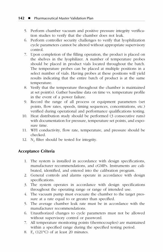
142 � Pharmaceutical Master Validation Plan
5. Perform chamber vacuum and positive pressure integrity verifica-tion studies to verify that the chamber does not leak.
6. Perform controller security challenges to verify that lyophilizationcycle parameters cannot be altered without appropriate supervisorycontrol.
7. Upon completion of the filling operation, the product is placed onthe shelves in the lyophilizer. A number of temperature probesshould be placed in product vials located throughout the batch.The temperature probes can be placed at multiple positions in aselect number of vials. Having probes at these positions will yieldresults indicating that the entire batch of product is at the sametemperature.
8. Verify that the temperature throughout the chamber is maintainedat set point(s). Gather baseline data on time vs. temperature profilein the event of a power failure.
9. Record the range of all process or equipment parameters (setpoints, flow rates, speeds, timing sequences, concentrations, etc.)verified during operational and performance qualifications testing.
10. Heat distribution study should be performed (3 consecutive runs)with documentation for pressure, temperature set points, and expo-sure time.
11. WFI conductivity, flow rate, temperature, and pressure should bechecked.
12. N2 filter should be tested for integrity.
Acceptance Criteria
1. The system is installed in accordance with design specifications,manufacturer recommendations, and cGMPs. Instruments are cali-brated, identified, and entered into the calibration program.
2. General controls and alarms operate in accordance with designspecifications.
3. The system operates in accordance with design specificationsthroughout the operating range or range of intended use.
4. The vacuum pump must evacuate the chamber to the target pres-sure at a rate equal to or greater than specified.
5. The average chamber leak rate must be in accordance with themanufacturer recommendations.
6. Unauthorized changes to cycle parameters must not be allowedwithout supervisory control or password.
7. All temperature monitoring points (thermocouples) are maintainedwithin a specified range during the specified testing period.
8. F0 (121°C) of at least 20 minutes.
SL3305_C18_fm Page 142 Thursday, November 8, 2001 3:24 PM
Qualification of Process Equipment � 143
9. Water for Injection (WFI) must meet specifications.10. N2 filter must pass the integrity test.
18.30 LAMINAR FLOW UNIT
Test Functions
1. Perform Installation Qualification.2. Perform general operational controls verification testing.3. Operate system throughout the range of operating design specifi-
cations or range of intended use.4. Integrity test all HEPA filters with dioctylphthalate (DOP) smoke.5. Measure the average face velocity of each terminal HEPA filter.
Measure the average velocity 1 ft above the workspace, exposedproduct areas, or exposed component areas in all Class 100 laminarflow rooms or areas.
6. Verify that system air flows have been balanced to within ±10% ofdesign criteria.
7. Verify that air flow patterns within Class 100 laminar flow areasare nonturbulent and unidirectional by performing smoke-stick airflow studies and recording the test on videotape.
8. Record the range of all process or equipment parameters (setpoints, flow rates, timing sequences, concentrations, etc.) verifiedduring Operational and Performance Qualifications testing.
9. Verification of particle count (Class 100).10. Verification of decontamination time.
Acceptance Criteria
1. The system is installed in accordance with design specifications,manufacturer recommendations, and cGMPs. Instruments are cali-brated, identified, and entered into the calibration program.
2. General controls and alarms operate in accordance with designspecifications.
3. The system operates in accordance with design specificationsthroughout the operating range or range of intended use.
4. HEPA filters are 99.99% efficient when tested with DOP smoke.5. All terminal HEPA filter face velocity measurements are within ±30%
of the average filter velocity.6. The average face velocity of terminal HEPA filters servicing Class
100 laminar flow rooms is 90 ft/min ±20% with no points below75 ft/min or above 105 ft/min.
SL3305_C18_fm Page 143 Thursday, November 8, 2001 3:24 PM
144 � Pharmaceutical Master Validation Plan
7. Directional air flows (as determined by room differential pressure)must be consistent with design drawings.
8. Each room must maintain the design temperature range.9. Air flow in Class 100 laminar flow areas must be nonturbulent and
unidirectional, as demonstrated by smoke-stick studies.10. AHU, fans, and heat exchanger operations meet or exceed their
respective design ratings.11. Particle count must meet specifications.
18.31 PASS-THROUGH
Test Functions
1. Perform Installation Qualification.2. Perform general operational controls verification testing.3. Operate system throughout the range of operating design specifi-
cations or range of intended use.4. Verify that both doors of the pass- through cannot be open
simultaneously.5. Verify that directional air flows are consistent with design drawings
by verifying relative differential air pressures.6. Verify air flow patterns by performing smoke-stick air flow studies
and recording the test on videotape.7. Integrity test HEPA filter with dioctylpthalate (DOP) smoke.8. Particle count test (Class 100).9. Air velocity.
Acceptance Criteria
1. The system is installed in accordance with design specifications,manufacturer recommendations, and cGMPs.
2. General controls and alarms operate in accordance with designspecifications.
3. The system operates in accordance with design specificationsthroughout the operating range or range of intended use.
4. Both doors of the pass-through should not be open simultaneously.5. Pass-through shall be under positive pressure in relation to adjacent
areas of other than an equal or higher Class 100 classification. Insterile powder handling areas, an airlock must be under negativepressure to prevent the movement of dust from one sterile areato another.
SL3305_C18_fm Page 144 Thursday, November 8, 2001 3:24 PM
Qualification of Process Equipment � 145
6. Air flow in Class 100 pass-through must be outward directional,as demonstrated by smoke-stick studies.
7. HEPA filter is 99.99% efficient when tested with DOP smoke.8. Particle count must meet specifications.9. Face velocity = 0.45 ±20%.
SL3305_C18_fm Page 145 Thursday, November 8, 2001 3:24 PM

SL3305_C18_fm Page 146 Thursday, November 8, 2001 3:24 PM
147
19
VALIDATION OF SUPPORT PROCESSES
19.1 WASHING OF COMPONENTS
The washing of components will be validated for each load configurationin the vial washer. Cycle Development Testing and Performance Qualifi-cation testing will qualify each washing process. A separate performancequalification and cycle development testing report will be written for eachload configuration. The processes will be considered validated when theacceptance criteria is met for three (3) successful consecutive runs.
Cycle Development Testing
Perform one or more cycle development test runs with vials to determineappropriate time for each cycle (wash and rinse), temperature for eachcycle, load size, WFI supply pressure, and air supply pressure.
Performance Qualification Test Functions
1. Identify and document the quantity and placement of vials in theload configuration. Determine load configuration from Cycle Devel-opment Test studies.
2. Prepare a full load of vials spiked with dye. Wash the vials as perthe proposed operating procedure. Inspect each vial for dye residue.
3. Spike three (3) sets of vials with NaCl solution. Allow vials to dryand then wash them per the proposed procedure. Baseline datawill be established using unwashed, NaCl-spiked vials. Test thewashed vials for conductivity (NaCl) and particulate count (WFI).
SL3305_C19_fm Page 147 Thursday, November 8, 2001 3:25 PM
148
�
Pharmaceutical Master Validation Plan
Acceptance Criteria
1. No dye residue is detected at >1 ppb in any of the washed vials.2. The rinse solution from each washed, NaCl-spiked vial must have
a conductivity <2 µmho.3. The rinse solution from each washed, NaCl-spiked vial must have
no precipitate when tested per USP 24 Monograph for SodiumChloride.
4. Both the rinse solutions from the NaCl-spiked and unspiked vialsmust have particulate counts that meet the specifications listed inUSP 24 Monograph for Physical Test, and Particulate Matter inInjections.
5. The rinse solutions from the NaCl spiked and unspiked vials mustmeet the specifications for Water for Injection listed in USP 24Monograph for Water for Injection.
6. The rinse solutions from the unspiked vials must have no morethan 0.25 EU/ml.
19.2 STERILIZATION OF COMPONENTS
The sterilization of components and equipment will be validated for eachload configuration using the cGMP autoclave. Cycle Development Testingand Performance Qualification Testing will qualify each sterilization pro-cess. A separate Performance Qualification and Cycle Development TestingReport will be written for each load configuration. The process will beconsidered validated when the acceptance criteria is met for three (3)successful consecutive runs.
Cycle Development Testing
Perform one or more cycle development test runs used in the loadconfiguration to determine appropriate cycle type, temperature and dwellperiod, hard-to-heat items or areas, load item preparation, and minimumand maximum load configurations.
Performance Qualification Test Functions
1. Identify and document the quantity, placement, and physicaldescription of each component to be included in the load config-uration. Determine the load configuration from Cycle DevelopmentTest studies.
SL3305_C19_fm Page 148 Thursday, November 8, 2001 3:25 PM
Validation of Support Processes
�
149
2. Perform load and chamber temperature mapping and verify thatthe temperature distribution in the chamber is uniform for the loadconfiguration, and that all measured points within the load con-figuration receive thermal treatment sufficient for sterilization. Per-form three (3) runs on the maximum load and a minimum of three(3) runs on the minimum load.
3. Perform microbiological challenge studies using the OverkillApproach Sterilization Validation. Place
Bacillus stearothermophilus
spores throughout the load configuration, at points where steampenetration may be incomplete, and at hard-to-heat locations.Perform a minimum of three (3) runs on the maximum loadconfiguration and a minimum of three (3) runs on the minimumload configuration. Perform spore quantification verification oneach manufacturer’s lot of spore strips or suspensions. Performmicrobiological challenge studies simultaneously with loadedchamber heat penetration and distribution studies.
4. Record the range of all process or equipment parameters (setpoints, flow rates, timing sequences, concentrations, etc.) verifiedduring cycle Development and Performance Qualifications testing.
Acceptance Criteria
1. During load and chamber temperature mapping, the maximumload configuration, the mean of the F
0
values from the singleslowest-to-heat point from each of the three (3) test runs minus 3standard deviations of the these three F
0
values must be greaterthan 20 min.
2. During load and chamber temperature mapping, the minimum loadconfiguration, the mean of the F
0
values from the single slowest-to-heat point from each of the three (3) test runs minus 3 standarddeviations of the these three F
0
values must be greater than 20 min.3. During microbiological challenge studies, all
Bacillus stearother-mophilus
spore strips/suspensions must show negative test for thegrowth of
B. stearothermophilus
.4. During microbiological challenge studies, positive controls for the
B. stearothermophilus
spore strips/suspensions must test positivefor the growth of
B. stearothermophilus
.5. During Microbiological Challenge studies, spore strips/suspension
quantification test must indicate that the population of each man-ufacturer’s lot of spore strips/suspensions is within ±50% of theirlabeled population.
SL3305_C19_fm Page 149 Thursday, November 8, 2001 3:25 PM
150
�
Pharmaceutical Master Validation Plan
19.3 DEPYROGENATION OF COMPONENTS
The depyrogenation of components will be validated for each load con-figuration using the depyrogenation hot air sterilization tunnel. CycleDevelopment Testing and Performance Qualification Testing will qualifyeach depyrogenation process. A separate Performance Qualification andCycle Development Testing Report will be written for each load configu-ration. The processes will be considered validated when the acceptancecriteria is met for three (3) successful consecutive runs.
Cycle Development Testing
Perform one or more cycle development test runs with item used in theload configuration to determine appropriate cycle type, temperature anddwell period, hard-to-heat items or areas, load item preparation, andminimum and maximum load configurations.
Performance Qualification Test Functions
1. Identify and document the quantity, placement, and physicaldescription of each component to be included in the load config-uration. Determine load configurations from Cycle DevelopmentTest studies.
2. Perform load and chamber temperature mapping and verify thatthe temperature distribution in the chamber is uniform for the loadconfiguration, and that all measured points within the load con-figuration receive thermal treatment sufficient for depyrogenation.Perform three (3) runs on the maximum load and a minimum ofthree (3) runs on the minimum load.
3. Perform pyrogen challenge studies and verify through laboratorytesting that the endotoxin contents of all indicators in each loadare reduced by a minimum of 3 logs. Endotoxin reduction of 3logs or greater will also ensure a greater than 12 log reduction ofbiological organisms.
4. Record the range of all process or equipment parameters (setpoints, flow rates, timing sequences, concentrations, etc.) verifiedduring Cycle Development and Performance Qualifications Testing.
Acceptance Criteria
1. Temperature distribution thermocouples in the heat penetrationand distribution test studies for three (3) consecutive runs must bewithin ±5°C of the mean chamber temperature during the dwellperiod at any one print interval.
SL3305_C19_fm Page 150 Thursday, November 8, 2001 3:25 PM
Validation of Support Processes
�
151
2. During heat penetration studies, all thermocouples must receive aminimum temperature of 250°C. F
H
(250°C) must be calculated.3. The endotoxin content of all endotoxin indicators must be reduced
to levels of <0.025 EU (or undetectable), or at least demonstratea minimum of 3 log reduction for three (3) consecutive runs athalf-cycle.
4. Positive controls for endotoxin indicators must yield a minimumof 1000 EU.
5. Negative controls for endotoxin indicators must be <0.03 EU/ml.
19.4 ASEPTIC FILLING VALIDATION (MEDIA FILL STUDIES)
Protocols will be developed to demonstrate that the product is asepticallyfilled into a final dosage container. These studies will consist of exposingmedia capable of supporting a broad spectrum of microbiological growthto all operations and procedures normally performed during the manu-facturing process. Vials will be filled at the normal working volume. Eachstudy will include fi lling approximately 3000 vials/ampoules. Thevials/ampoules will be incubated at 20 to 25°C for 14 days.
“Worst-case,” challenges such as personnel breaks, equipment adjust-ments, and additional personnel in the fill room will be incorporated intoall media fill studies. Stoppers and vials or ampoules will be sterilized.The time between sterilization and the start of the first media fill will bethe maximum validated storage time for sterile stoppers, vials, andampoules, provided the media fills meet all other acceptance criteria.
All environmental monitoring supplies will be growth promoted onthe release date and fill date. Agar strips will be growth promoted afterbeing exposed to the same environmental conditions as those experiencedduring the fill. Growth promotion will be performed for organisms requiredby USP 24 Monograph for Indigenous Organisms and Anaerobes usingvials/ampoules collected during the fill and upon completion of the 14-dayincubation period.
The protocol will include acceptance criteria for sterility assurance leveland growth promotion.
Also included will be details of data collection, growth promotionsampling, environmental and personnel monitoring schedule, personnelmovement documentation, incubation time and temperature, etc.
Acceptance Criteria
Upon successful completion (end-point contamination level of not morethan 0.1%) of three (3) consecutive media fills for the vial/stopper com-bination and ampoules, the aseptic process will be considered validated.
SL3305_C19_fm Page 151 Thursday, November 8, 2001 3:25 PM
152
�
Pharmaceutical Master Validation Plan
19.5 CROSS-CONTAMINATION CONTROL
Test Functions
1. Verification of HVAC design, zoning of air handling units, airlocks,room pressure differentials, recirculation vs. once-through air han-dling systems, room air distribution, use of HEPA filters on mainreturn ducts to air handling plants, supply and return duct work,fresh air intakes and exhaust for buildings A, B, and C.
2. Verification of materials and product dispersal around manufactur-ing facility in buildings A, B, and C.
3. Verification of spread of materials and products during maintenanceand cleaning of environmental and process air handling plant andequipment.
4. Verification of containment of materials and products duringprocessing.
5. Verification of dust collection system as per design.6. Verification of movement of personnel, gowning, and laundry as
per design.7. Verification of utilities design, mix-up, identification, check valves,
and back-flow prevention.8. Verification of facility design, architectural finishes, and room layout.9. Verification of equipment design, construction materials, clean
in-place (CIP) units where possible, and cleaning out-of-placepractice.
10. Verification of cross-contamination prevention by performing airsampling and machine swabs.
11. Verification of prevention of cross-contamination by cleaning sys-tem validation.
12. Verification of prevention of cross-contamination through residualanalysis of finished products.
13. Verification of pallets transfer and interlocks as per design.
Acceptance Criteria
1. The system is installed in accordance with design specificationsbased on manufacturer recommendations and cGMP guidelinesand documented.
2. Materials and product dispersal around manufacturing facility inbuildings A, B, and C with design specification.
3. Spread of materials and products during maintenance and cleaningof environmental and process air handling plant and equipment ismaintained and demonstrated through environmental monitoring.
SL3305_C19_fm Page 152 Thursday, November 8, 2001 3:25 PM

Validation of Support Processes
�
153
4. Containment of materials and products during processing is dem-onstrated through environmental monitoring.
5. Dust collection system operates in accordance with design speci-fications throughout the operating range or range of intended use.
6. General control of movement of personnel, gowning, and laundryis demonstrated through SOP compliance and training.
7. General controls, alarms, identification, and interlocks operate inaccordance with design specifications.
8. Facility construction and architectural finishes demonstrate adher-ence to specifications and cGMPs.
9. Equipment design, construction materials, CIP, and cleaningout-of-place practice are in compliance with cGMPs.
10. Air sampling and machine swabs results meet the acceptancecriteria established.
11. Area/equipment cleaned in accordance with the written SOPs andmeet the acceptance criteria.
12. The pallet transfer units and interlocks operate as per design andin accordance with the written SOPs.
19.6 COMPUTERIZED PHARMACEUTICAL SYSTEM
Test Functions
1. Perform Installation Qualification.2. Confirm that hardware and software descriptions are available.3. Confirm that the documentation is appropriate, up-to-date, relevant,
and complete.4. Verify the digital transmission inputs and outputs as appropriate.5. Verify analog transmission inputs and outputs as appropriate.6. Verify data entry and boundary testing as appropriate.7. Verify access control testing as appropriate.8. Verify SOPs for operation, maintenance, and change control.9. Verify training records.
10. Verify system recovery procedure.
Acceptance Criteria
1. The system is installed in accordance with design specificationsbased on manufacturer recommendations and cGMP guidelines.Instruments are calibrated, identified, and entered into the calibra-tion program.
2. Hardware and software systems are verified as per manual.
SL3305_C19_fm Page 153 Thursday, November 8, 2001 3:25 PM
154
�
Pharmaceutical Master Validation Plan
3. The documentation is appropriate, up-to-date, relevant, and com-plete as per protocol.
4. The digital transmission inputs and outputs are verified.5. The analog transmission inputs and outputs are verified.6. The data entry and boundary testing meets the specification design.7. The access control testing meets the specification design.8. SOPs are available for operation, maintenance, and change control.9. Training records are available.
10. System recovery procedure is available.
SL3305_C19_fm Page 154 Thursday, November 8, 2001 3:25 PM
155
20
QUALITY ASSURANCE/CONTROL
LABORATORY VALIDATION
The Quality Assurance/Control Laboratory serves one of the most criticalfunctions in the ABC Pharmaceutical facility. Consequently, a comprehen-sive validation program will be initially performed for procedures andequipment used for all products, as well as any analytical proceduresrequired for the first scheduled product. Thereafter, the analytical methodsrequirements and resulting validation will be evaluated and performed asnecessary for each new product.
The Quality Assurance/Control staff will evaluate in detail the analyticalrequirements and the procedures. Where applicable, the validated labo-ratory equipment and analytical methods will be utilized.
Equipment and methods will be operated/performed in accordancewith cGMPs. Instruments will be calibrated, automatic analyzers andequipment will be qualified; computer-related systems will be validated;analytical methods from USP/NF will be verified; and glassware prepara-tion, media preparation, and noncompendial methods will be validated.
20.1 LABORATORY EQUIPMENT QUALIFICATION
Laboratory equipment such as incubators, refrigerators, laminar flowhoods, depyrogenation ovens, sterilizers, etc., will be qualified using thesame approach as that used for process equipment and utility systems.
The processes of sterilization and depyrogenation of laboratory equip-ment and microbiological media will be validated using the same approachas that used for production processes. Test functions and acceptance
SL3305_C20_fm Page 155 Thursday, November 8, 2001 3:26 PM
156
�
Pharmaceutical Master Validation Plan
criteria for these validation protocols are summarized in Chapter 19.2 and19.3, respectively.
Automatic analyzers will be qualified by performance of Installationand Operation Qualifications. The purpose of the qualification for auto-matic analyzers is the same as that for any other piece of cGMP equipment:to verify that it has been installed and operates in accordance with designspecifications, manufacturer recommendations, and cGMPs.
Test Functions
1. Perform Installation Qualification.2. Perform general operational controls verification testing.3. Operate system throughout the range of operating design specifi-
cations or range of intended use.
Acceptance Criteria
1. The system is installed in accordance with design specifications,manufacturer recommendations, and cGMPs. Instruments are cali-brated, identified, and entered into the calibration program.
2. General controls and alarms operate in accordance with designspecifications.
3. The system operates in accordance with design specificationthroughout the operating range of intended use.
20.2 COMPUTER-RELATED SYSTEMS USED IN THE QA/QC LABORATORY
Computer-related systems used in the laboratory for control of automaticanalyzers and/or laboratory information management systems will bevalidated; however, additional emphasis will be placed on the followingspecific concerns:
�
Authorization for data entry
�
Features to prevent deletion of data (changes must be made asamendments; deletion of data is not permitted)
�
Security of the database (database must be as tamper-proof aspossible)
�
Procedures for ensuring the validity of the data
SL3305_C20_fm Page 156 Thursday, November 8, 2001 3:26 PM
157
21
cGMP PROCEDURES AND PROGRAMS
21.1 ENGINEERING CHANGE CONTROL
Change Control will be written to ensure that systems and processesremain in a state of validation. The procedure outlines steps to followwhen a change is proposed. The change control program ensures thatproposed changes are reviewed and approved by appropriate departmen-tal representatives prior to initiating changes. The review also defines therequired tests and documentation to be performed to verify that the system,equipment, and process remain in a validated state.
21.2 CALIBRATION
The calibration program will ensure that all critical instruments used aremaintained in a calibrated state. Specific acceptance criteria limits will beestablished based on system and processing requirements.
Periodic calibration orders generated by the calibration program willcontain information such as department, location, accuracy, data sheetnumber, SOP number, etc. needed by the calibration technician. Instru-mentation in this program will include, but is not limited to, timers,monitoring probes (temperature, relative humidity, etc.), pressure gauges,balances, etc.
Each instrument will be placed in one of three categories: Critical,Non-critical, and Convenience. A critical instrument is one whose failureor precision directly affects the quality, purity, and/or integrity of theproduct. A non-critical instrument does not fall into the Critical category,but can be used in troubleshooting, mainting, controlling, or monitoring
SL3305_C21_fm Page 157 Thursday, November 8, 2001 3:27 PM
158
�
Pharmaceutical Master Validation Plan
a process or test that is potentially hazardous. A Convenience instrumentis any instrument that does not fall into the Critical or Non-critical category.
Instrument calibrations are required at intervals based on the criticalityof the instruments, instrument capability, and instrument calibration his-tory. An instrument will also be calibrated following the repair of theinstrument, following the repair of the system that the instrument ismonitoring/controlling, if the repair could have affected the instrumentaccuracy, and/or after installing the instrument into a system. All equip-ment used to perform calibrations will be calibrated to standards traceableto the National Institute of Standards and Technology (NIST) or otherapproved standards and maintain the following:
�
Standards
�
Instrument numbering system
�
Instrument calibration files
21.3 PREVENTIVE MAINTENANCE PROGRAM
A preventive maintenance program is developed and implemented tomaintain production systems in proper working condition and reduceequipment malfunctions.
The manufacturer’s specifications, past experience, and history of theequipment will be used to establish the preventive maintenance schedule.Procedures will be developed for issuing work orders, performing themaintenance work, documenting the work in the proper logbooks andfiles, frequency of performing preventive maintenance, reviewing theimpact of maintenance on validation state, etc.
21.4 STANDARD OPERATING PROCEDURES (SOPs)
The standard operating procedure (SOP) system is established, procedurenumber WXY-001 “for Preparation, Approval and Issue of Standard Oper-ating Procedure.” The procedure includes instructions for preparation,review, approval, issuance, control, modification, and document retention.The modification to procedure WXY-001 will include establishment of thereview and approval.
All new procedures will be written to address all activities performedin the facility, including documentation systems, raw materials handlingand control, personnel movement, equipment operation, product formu-lation, handling and testing, etc.
SL3305_C21_fm Page 158 Thursday, November 8, 2001 3:27 PM
cGMP Procedures and Programs
�
159
21.5 FACILITY CLEANING AND SANITIZATION
A comprehensive Facility Cleaning and Sanitization Program with an initialschedule for each room will be developed, with procedures based on theinitial sanitization validation results, the criticality of operation performedin each area, and the frequency of use. The initial schedule will be modifiedas necessary based on routine environmental monitoring. The environ-mental monitoring results will be compared against alert and action levels.
The program will include a schedule for rotation of sanitizing agentsto prevent the proliferation of resistant organisms in the facility. Cleaningand sanitizing will be documented in logbooks, the status of each roomwill be marked, and all cleaning will be performed per written procedures(SOPs). Sanitizing agents will be routinely monitored for bacterial con-tamination. Logbooks will be periodically reviewed by Quality Assurance.
21.6 ENVIRONMENTAL MONITORING PROGRAM
A comprehensive Environmental Monitoring Program will be developedto ensure that the environmental conditions are maintained within vali-dated limits. The program will include critical utility systems, microbio-logical testing areas, and manufacturing areas. Parameters that may affectthe integrity of the product or manufacturing process, personnel safety,or the cleaning and sanitization program will be monitored. These param-eters include nonviable particulate, bioburden, purity, identity, temperatureand relative humidity.
Most of the testing procedures required for this program will be adaptedfrom Quality Assurance and Quality Control procedures. The existinganalytical and microbiological procedures have been validated or verified.Any additional analytical or microbiological test procedures will be vali-dated or verified.
Alert and action levels for each parameter in each area or critical utilitywill be established based on the results from validation testing, compendiarequirements, and cGMPs. Area or room limits will be based on theenvironmental data collected during the validation of the aseptic fillingprocess validation. Specific action plans will be developed for addressingexcursions beyond alert and action limits for each area or utility.
21.7 HEPA FILTER INTEGRITY TESTING
A procedure will be developed that identifies the certification requirementsfor all High Efficiency Particulate Air (HEPA) filters in the Injectable facility.This will include HEPA filters mounted in ceilings, flow hoods, biosafety
SL3305_C21_fm Page 159 Thursday, November 8, 2001 3:27 PM
160
�
Pharmaceutical Master Validation Plan
cabinets, cleanroom vacuum cleaners, microbiology testing rooms, and airhandling units. HEPA filters will be certified by the DOP test method forproper face velocity profile, velocity at the workspace, and integrity. HEPAfilters will be initially tested as part of the installation, and all testdocumentation will be verified and included in the Validation Package forthe HVAC system, biosafety cabinets, and laminar flow hoods. TerminalHEPA filters servicing Class 100 areas will be certified more frequentlythan those in Class 1000 or greater areas.
21.8 FILTER INTEGRITY TESTING
A filter testing procedure will be developed to ensure that bacterialretentive air and liquid filters are integrity tested and replaced as necessary.This program will include those filters not directly in the process stream,such as vent filters on tanks and autoclaves, and compressed gas filters.This procedure will include filter integrity testing instructions, schedules,and acceptable test results.
Filters that are directly in the process stream, such as product steril-izing filters and media sterilizing filters, will be tested before and afterthe processing of each batch and documented in the actual batchproduction records.
The automatic filter integrity tester will be operationally qualified, andall test parameters and acceptable test results will be verified in theOperational and Performance Qualifications of the equipment, for exam-ple, the Sterilizing Filter and the Media Preparation System.
21.9 LABEL CONTROL PROGRAM
The label control program and procedure includes labeling requirements.The program is structured to ensure the following:
�
Issuance is strictly controlled and performed by authorized per-sonnel only.
�
Labeling materials issued are carefully examined for identity andconformity to the labeling specified in the batch production recordfor the product being labeled.
�
Reconciliation of quantities issued, used, and returned, as well asinvestigation of any discrepancies.
�
Excess labeling bearing lot numbers is destroyed.
�
Returned labeling is stored in a manner to prevent mix-ups andprovide proper identification.
SL3305_C21_fm Page 160 Thursday, November 8, 2001 3:27 PM
cGMP Procedures and Programs
�
161
21.10 cGMP TRAINING
A GMP training system which ensures that all personnel are trained incurrent Good Manufacturing Practices as required by Title 21 CFR Part211.25 (a) will be developed in all operations that they are required toperform. The program will be designed so that training is performedand/or coordinated by the Quality Assurance Manager. All training willbe documented and retained in a training file.
21.11 EQUIPMENT LOGBOOKS, STATUS TAGS, AND ROOM CLEARANCE CHECKLISTS
A system for determining the day-to-day status of critical systems, areas,and activities will be developed. Activities such as batch production,cleaning, preventive maintenance, calibration, load sterilization, etc. willbe controlled and documented by procedure in logbooks and reviewedand filed as critical processing documentation.
Status tags will be utilized to indicate the status, such as under cleaning,clean, in-process, quarantine, released, etc. Procedures will be developedfor the placement and removal of status tags.
A checklist will be developed to establish proper room clearance priorto initiating a production batch. Checklist development, handling, control,and review will be incorporated into procedures for ongoing control.
21.12 VALIDATION FILES
A program to ensure control of critical system documentation will beestablished. The files will be controlled by QA. Validation and centralizedfor easy retrieval. Equipment validation data such as operating and servicemanuals, purchase orders, manufacturer specifications, as-built drawingsand schematics, spare parts lists, and any other information pertaining tothe system will be included in the file. Separate validation files for Facility,Systems, and Process validation of each product, including all related data,will be maintained. Procedures will be developed to create files for newequipment, update information for existing equipment, control, removal,and return of information, etc.
SL3305_C21_fm Page 161 Thursday, November 8, 2001 3:27 PM

SL3305_C21_fm Page 162 Thursday, November 8, 2001 3:27 PM
163
22
VALIDATION SCHEDULE
Validation schedule is the last but not the least important component ofoverall validation activity. The validation schedule prepared for ABCPharmaceutical Industries defines a time line chart for the execution ofIQ, OQ, PQ, PV, CLV, etc., to attain sufficient documented evidence togive reasonable assurance that the process under consideration doesand/or will do what it purports to do.
Room No.
Description of Equipment/Facility/Utilities/
Process/Cleaning
Validation Requirement
IQ/OQ/PQ/PV/CLV etc.
YearQuarter
1Q 2Q 3Q 4Q
SL3305_C22_fm Page 163 Thursday, November 8, 2001 3:28 PM

SL3305_C22_fm Page 164 Thursday, November 8, 2001 3:28 PM

165
23
DRAWINGS FOR ABC PHARMACEUTICAL PLANT
SL3305_C23_fm Page 165 Thursday, November 8, 2001 3:29 PM
166
�
Pharmaceutical Master Validation Plan
S. No. Description Drawing No.
1
Machine Layout
Building A Machine - 01Building B Machine - 02Building C Machine - 03
2
Civil Layout
Building A Civil - 01Building B Civil - 02Building C Civil - 03
3
Nitrogen Piping Layout
Building A Piping - 01Building B Piping - 02Building C Piping - 03
4
Chilled Water Piping Layout
Building A Piping - 01Building B Piping - 02Building C Piping - 03
5
Steam Piping Layout
Building A Piping - 01Building B Piping - 02Building C Piping - 03
6
Hot Water Piping Layout
Building A Piping - 01Building B Piping - 02Building C Piping - 03
7
Compressed Air Piping Layout
Building A Piping - 01Building B Piping - 02Building C Piping - 03
8
Deionized Water Piping Layout
Building A Water - 01Building B Water - 02Building C Water - 03
SL3305_C23_fm Page 166 Thursday, November 8, 2001 3:29 PM
Drawings for ABC Pharmaceutical Plant
�
167
9
Water for Injection Piping Layout
Building C Water - 01
10
HVACGA & Ducting Layout
Building A HVAC - 01Building B HVAC - 02Building C HVAC - 03
S. No. Description Drawing No.
SL3305_C23_fm Page 167 Thursday, November 8, 2001 3:29 PM

SL3305_C23_fm Page 168 Thursday, November 8, 2001 3:29 PM
169
RECOMMENDED READING
Baker, G.S. and Rhodes, C.T.,
Modern Pharmaceutics
, Marcel Dekker, New York, 1996.Berry, I.R. and Harpaz, D.,
Validation of Bulk Pharmaceutical Chemicals
, InterpharmPress, Buffalo Grove, IL, 1997.
Berry, I.R. and Nash, R.A.,
Pharmaceutical Process Validation
, Marcel Dekker,New York, 1993.
British Pharmacopoeia
, 1993.Carleton, F.J. and Agalloco, J.P,
Validation of Aseptic Pharmaceutical Processes
, MarcelDekker, New York, 1986.
Cloud, P.,
How to Develop and Manage Qualification Protocols for FDA Compliance
,Interpharm Press, Buffalo Grove, IL, 1999.
Cloud, P.,
Pharmaceutical Equipment Validation Qualification
, Interpharm Press,Buffalo Grove, IL, 1998.
Commission of the European Communities, The Rules Governing Medicinal Products inthe European Community, Vol. 4, Guide to II / 2244 / 87-EN, Rev. 3, January 1989.
DeSain, C.,
Documentation Basics That Support Good Manufacturing Practices
,Advanstar Communications, Cleveland, OH, 1993.
Development Pharmaceutics and Process Validation, CPMP, 1988.European Community,
Good Manufacturing Practice for Medical Products
, 1992.FIP, Guidelines for Good Validation Practice, 1988.Gibson, W. and Evans, K.P.,
Validation Fundamentals How to, What to, When toValidate
, Interpharm Press, Buffalo, Grove, IL, 1998.
Guide to Inspection of High Purity Water System
, Interpharm Press, Buffalo Grove,IL, 1993.
Guide to Inspection of Microbiological Pharmaceutical Quality Control Laboratories
,Interpharm Press, Buffalo Grove, IL, 1993.
Guideline of the Commission for Principles of Good Manufacturing Practice for MedicalProducts, Directive 91/356/EEC, 1991.
Huber, L.,
Validation and Qualification in Analytical Laboratories
, Interpharm Press,Buffalo Grove, IL, 1998.
Huber, L.,
Validation of Computerized Analytical System
, Interpharm Press, BuffaloGrove, IL, 2000.
Isaacs, A., Validating machinery with electronic control systems,
Manufacturing Chem-ist
, p. 19, February 1992.ISPE, Bulk Pharmaceutical Chemicals, 1996.ISPE, Oral Solid Dosage Forms, 1997.Knapp, J.Z. and Kushner, H.K., generalized methodology for evaluation of parenteral
inspection,
J. Parenteral Drug Assoc.
, Vol. 34 (I), January–February 1980).Loftus, B.T and Nash, R.A.,
Pharmaceutical Process Validation
, Marcel Dekker,New York, 1984.
Parenteral Drug Association, Validation of Dry Heat Process Used for Sterilization andDepyrogeneration, Technical Report No. 3, 1981.
SL3305_CRecRead_fm Page 169 Thursday, November 8, 2001 3:30 PM
170
�
Pharmaceutical Master Validation Plan
PIC, Principles of Qualification and Validation in Pharmaceutical Manufacture, PICDocument PH 1/96, 1996.
PMA’s Computer Systems Validation Committee, Computer system validation — stayingcurrent: introduction,
Pharm. Technol.
, 13(5), 60, 1989.PMA’s Computer Systems Validation Committee, Validation concepts for computer
systems used in the manufacture of drug products,
Pharm. Technol
., 10(5),24, 1986.
Stokes, T., Branning, R.C., Chapman, K.G., Hamblock, H., and Trill, A.J.,
Good ComputerValidation Practices: Common Sense Implementation
, Interpharm Press, BuffaloGrove, IL, 1994.
United States Pharmacopoeia 24
, 2000.
Validation Documentation Inspection Guide
, Interpharm Press, Buffalo Grove, IL, 1993.WHO,
Guidelines on the Validation of Manufacturing Process
, 1996.Wingate, G., Validating Automated Manufacturing and Laboratory Applications: Putting
Principles into Practice, Interpharm Press. Buffalo Grove, IL, 1997.
SL3305_CRecRead_fm Page 170 Thursday, November 8, 2001 3:30 PM
171
INDEX
A
Air, compressed, 68Air-conditioning,
see
HVAC systemAseptic fill products, process flow,
variables, responses, 110Autoclave
performance qualification of, 148–149qualification of, 136–138
B
Bracketing, products and equipment, 26–27
Building(s)description of, 39, 44–46validation of, 89–90
C
Calibration program, 83, 157–158validation team member from, 6
Capping machine, qualification of, 132–133
Capsulation, qualification of, 119Capsule(s), process flow, variables,
responses, 104Capsule polisher, qualification of,
120–121Carbon dioxide, 68
validation of, 97–98Cartonater, qualification of, 133–134Certification, for use in manufacturing, 79Certification package requirements, 75Chilled water, 68Civil work, 89–90Class I equipment, 73Class II equipment, 73Class III equipment, 73Cleaning/sanitization, facility, 159Cleaning validation, 24–27
Commuting mill, qualification of, 115–116
Compressed air, 68validation of, 95–96
Computer systems, in quality control/assurance laboratory, 156
Computer validation, 27–29Computerized pharmaceutical system,
153–154Coversheet, 31Cream/ointment filling machine,
qualification of, 130Cross-contamination control, 152–153Current good manufacturing practice
(cGMP), xiii, 37, 76calibration in, 157–158Engineering Change Control in, 157environmental monitoring system in,
159equipment logbooks in, 161facility cleaning and sanitization in,
159filter testing in, 160HEPA filter testing in, 159–160label control program in, 160preventive maintenance in, 158room clearance checklists in, 161standard operating procedures in, 158status tags in, 161training in, 161validation files in, 161
Cycle development, 77Cycle development testing,
see
specific equipment
D
Decision-making, xv–xviDeionized water, 67Design, validation, 72–74
SL3305_Index_fm Page 171 Thursday, November 8, 2001 3:31 PM
172
�
Pharmaceutical Master Validation Plan
Design qualification, 14–15Disposable syringe(s), process flow,
variables, responses, 111Document control, validation team, 4–6Document structure, 31Drainage system, facility, 90Drop(s), process flow, variables,
responses, 106Drop filling machine, qualification of, 129Drop manufacturing vessel, qualification
of, 124–125Dry heat sterilizer, qualification of,
138–139Dry production, 40
building description for, 44equipment description for, 47–49HVAC description for, 57–59process description for, 101–104protocols and procedures for, 79–80
Dryer, qualification of, 116–117
E
Electric power, 69Emergency power, validation of, 99–100Emulsifying mixer, qualification of,
126–127Engineering Change Control in, 157Engineering Change Control program, 77Enhanced Turn-Over Package (ETOP),
74–75Environmental monitoring system, 159Equipment
certification package requirements for, 75
classification of, 73–74description of,
see
Equipment description
numbering system for, 32process, qualification of, 115–145
autoclave, 136–138capping machine, 132–133capsulation machine, 119capsule polisher, 120–121cartonater, 133–134commuting mill, 115–116cream/ointment filling machine,
130drop filling machine, 129
drop manufacturing vessel, 124–125
dry heat sterilizer, 138–139dryer, 116–117emulsifying mixer, 126–127filter press, 127freeze dryer, 141–143labeling machine, 131–132laminar flow units, 143–144lyophilizer, 141–143mixer, 125–126overprinting machine, 134–135pass-through, 144–145powder filling machine, 119–120semisolids manufacturing vessel,
128shrink-wrapping machine, 134steam sterilizer, 136–138suppository filling machine,
130–131suspension filling machine, 129suspension manufacturing vessel,
123–124syrup filling machine, 129syrup manufacturing vessel,
122–123tablet coating machine, 121–122tablet compression machine, 118tray and rack washer, 135–136V-shell blender, 117–118vials/ampoules/syringes filling
machine, 140–141vials/ampoules washer, 139–140
Equipment description, 39dry production, 47–49liquid and semisolid production, 49–50overprinting, 53parenterals production, 51–53product development laboratories, 55quality assurance, 54quality control, 53–54
Equipment logbooks, 161
F
Facilitycleaning and sanitization of, 159description of, 37–38
building(s), 39
SL3305_Index_fm Page 172 Thursday, November 8, 2001 3:31 PM
Index
�
173
equipment, 39process, 39–42
drawings of, 166–167line capacity of, 38–39
Filling equipment, qualification ofcream/ointment filling machine, 130drop filling machine, 129powder filling machine, 119–120suppository filling machine, 130–131suspension filling machine, 129syrup filling machine, 129vials/ampoules/syringes filling
machine, 140–141Filling process validation, 151Filter press, qualification of, 127Filter testing, 159–160, 160Final Report, 78Final Report Package, 78Freeze dryer, qualification of, 141–143
G
Good laboratory practice, xiii
H
Heating, ventilation, and air-conditioning,
see
HVAC system
HEPA filter testing, 159–160Hot air tunnel
performance qualification of, 150–151qualification of, 138–139
HVAC system, 69–70description of,
see
HVAC system description
monitoring document for, 70validation of, 98–99validation team member for, 6
HVAC system descriptionfor dry production, 57–59for liquid and semisolid production,
60–61for overprinting area, 64for parenterals production, 62–64for product development laboratory,
66for quality assurance, 66for quality control, 65
I
Injectables production, 41Installation Qualification, 17–18, 74–75
general acceptance criteria for, 30protocols for, 75–76
L
Label control program, 160Labeling machine, qualification of,
131–132Laminar flow unit, qualification of,
143–144Line capacity, 38–39Liquids and semisolids production, 40
building description for, 45equipment description for, 49–50equipment validation of,
see
Equipment
HVAC description for, 60–61process description for, 105–107protocols and procedures for, 80–81
Lyophilized products, process flow, variables, responses, 113
Lyophilizer, qualification of, 141–143
M
Maintenance, preventive, 85Media fill studies, 151Mixer, qualification of, 125–126
N
Nitrogen, 68validation of, 96–97
Numbering system, 32–33
O
Ointments, process flow, variables, responses, 107
Operational Qualification, 18–20, 74–75general acceptance criteria for, 30protocols for, 76
Overprinting areaequipment description for, 53
SL3305_Index_fm Page 173 Thursday, November 8, 2001 3:31 PM
174
�
Pharmaceutical Master Validation Plan
HVAC description for, 64Overprinting machine, qualification of,
134–135
P
Packaging, validation team member from, 6
Parenterals productionbuilding description for, 46equipment description for, 51–53HVAC description for, 62–64process descriptions for, 109–113protocols and procedures for, 81–82
Pass-through equipment, qualification of, 144–145
Performance Qualification, 20–21general acceptance criteria for, 30protocols for, 77for support processes, 147–154
Plant steam, validation of, 91–92Powder filling, qualification of, 119–120Powder for suspensions, process flow,
variables, responses, 103Power,
see
Electric power; Emergency power
Preventive maintenance program, 85, 158Process description, 39–42,
see
also
Dry production; Liquids and semisolids production; Parenterals production
Process equipment,
see
EquipmentProcess Validation, 22–23
protocols for, 78,
see
also
Dry production; Liquids and semisolids production; Parenterals production
Product development laboratoryequipment description for, 55HVAC description for, 66validation team member from, 7
Productiondry oral, 40injectables, 41liquid and semisolid oral, 40validation team member from, 6
Pure steam, 68validation of, 92–93
Purified water, 67
Q
Qualification,
see
Validation/qualificationQuality assurance
computer related systems used in, 156equipment description for, 54HVAC description for, 66qualification of laboratory equipment
for, 155–156validation of, 155validation team member from, 6
Quality Assurance Manager, 72Quality control
computer related systems used in, 156equipment description for, 53–54HVAC description for, 65qualification of laboratory equipment
for, 155–156validation of, 155validation team member from, 7
R
Resource requirement estimates, xviRevalidation, reasons for, 35–36Revisions, reasons for, xvii–xixRisk analysis, 16–17Room clearance checklists, 161
S
Sanitary water, 69Semisolids manufacturing vessel,
qualification of, 128Semisolids production,
see
Liquids and semisolids production
Shrink-wrapping machine, qualification of, 134
Standard operating procedures, key, 87Standard operating procedures (SOPs),
158Status tags, 161Steam, pure, 68Steam utilities, validation of, 91–93Sterilization process
hot air, validation of, 150–151steam, validation of, 148–149
Sterilization products, process flow, variables, responses, 112
SL3305_Index_fm Page 174 Thursday, November 8, 2001 3:31 PM
Index
�
175
Support process validation, 147–154Suppository(ies), process flow, variables,
responses, 107Suppository filling machine, qualification
of, 130–131Suspension(s), process flow, variables,
responses, 106Suspension filling machine, qualification
of, 129Suspension manufacturing vessel,
qualification of, 123–124Syringe(s), process flow, variables,
responses, 111Syringe filling machine, qualification of,
140–141Syrup(s), process flow, variables,
responses, 106Syrup filling machine, qualification of,
129Syrup manufacturing vessel, qualification
of, 122–123System development life cycle (SDLC),
27–29
T
Tablet(s), process flow, variables, responses, 102
Tablet coating, qualification of, 121–122Tablet compression, qualification of, 118Terminal sterilization products, process
flow, variables, responses, 112Test specification header, 31Title 21 CFR Part 211.25 (a), 161Tray and rack washer, qualification of,
135–136
U
Utility descriptioncarbon dioxide, 68chilled water, 68compressed air, 68deionized water, 67electric power, 69heating, ventilation and
air-conditioning, 69–70nitrogen, 68pure steam, 68
purified water, 67sanitary water, 69water for injection, 67
Utility system validationcarbon dioxide, 97–98compressed air, 95–96emergency power, 99–100HVAC, 98–99nitrogen, 96–97plant steam, 91–92pure steam, 92–93team member for, 6water for injection, 93–94
V
V-shell blender, qualification of, 117–118Validation, definition of, 2Validation documents, 74–75Validation files, 161Validation life cycle
concurrent, 13–14prospective, 10–11retrospective, 12–13
Validation master plan, 2,
see
also
Validation/qualification
approval of, xviapproval page for, xxbenefits of, xivCD-ROM copy of, xixin decision-making, xv–xvielements of, xviFDA definition of, xiii–xivresource requirement estimates in, xvirevision of, xvii–xix,
see
also
Revalidation
scope of, 2vulnerability assessment of, xvwriting, xiv–xv
Validation process, 72–74, 78in certification for use in
manufacturing, 79Cycle development, 77dry production protocols and
procedures, 79–80Engineering Change Control program,
77Installation Qualification protocols,
75–76
SL3305_Index_fm Page 175 Thursday, November 8, 2001 3:31 PM
176
�
Pharmaceutical Master Validation Plan
liquid and semisolid production protocols and procedures, 80–81
Operational Qualification protocols, 76
parenterals production protocols and procedures, 81–82
Performance Qualification protocols, 77
reporting, 78Validation project management, 71–72Validation/qualification
acceptance criteria in, 29–30,
see
also
specific process or equipment
cleaning, 24–27computer, 27–29concept of, 9–10design, 14–15documentation changes in, 32documentation format for, 31–32documentation numbering system for,
32–33general acceptance criteria in, 29–30,
see
also
specific process or equipment
installation, 17–18numbering system in, 32–33operational, 18–20performance, 20–21process, 22–23reporting, 29risk analysis, 16–17of support processes, 147–154
Validation report, 29
Validation schedule, 163Validation team
document control by, 4–6members of, 3organization chart of, 4packaging member of, 6product development laboratory
member of, 7production member of, 6quality assurance member of, 6quality control member of, 7responsibilities of, 3–7, 72in testing and procedure approval, 5utilities/calibration/HVAC member of,
6Ventilation,
see
HVAC systemVial/ampoule/syringe filling machine,
qualification of, 140–141Vial/ampoule washer
performance qualification of, 147–148
qualification of, 139–140
W
Washer(s)tray and rack, , qualification of,
135–136validation of, 147–148vials/ampoules, qualification of,
139–140Water consumption, 69Water production, 67–68
validation of, 93–94
SL3305_Index_fm Page 176 Thursday, November 8, 2001 3:31 PM


