GE Energy
Variable Frequency Transformers Grid Inter-tie
Variable Frequency Transformers
GE Energy revolutionizes the world of transmission solutions with its new Variable
Frequency Transformer (VFT). The VFT provides a simpler way to control power
between electrical grids than has previously been available.
What Is the VFT?
The VFT system is based on a combination of hydro generator and transformer
technologies. It consists of a rotary transformer, for continuously controllable phase
shift, together with a drive system and control, that adjust the angle and speed of the
rotary transformer, to regulate the power flow through the VFT.
What Function Does the VFT Provide?
The VFT system provides a means to control power between two grids. The grids
need not be synchronous. A common situation is where two grids of the same nominal
frequency cannot economically be directly connected with ac lines. The VFT allows
controlled power exchange between the grids, while retaining many of the inherent
virtues of an ac interconnection.
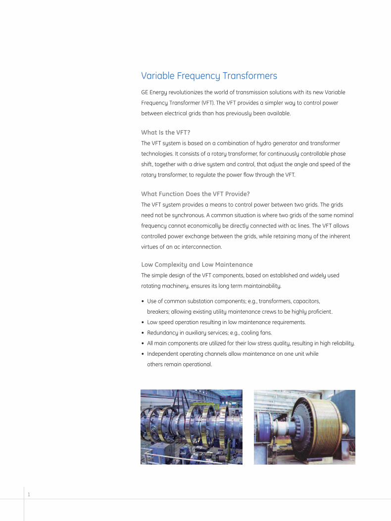
Low Complexity and Low Maintenance
The simple design of the VFT components, based on established and widely used
rotating machinery, ensures its long term maintainability.
• Use of common substation components; e.g., transformers, capacitors,
breakers; allowing existing utility maintenance crews to be highly proficient.
• Low speed operation resulting in low maintenance requirements.
• Redundancy in auxiliary services; e.g., cooling fans.
• All main components are utilized for their low stress quality, resulting in high reliability.
• Independent operating channels allow maintenance on one unit while
others remain operational.
1

VFT HVDC VSCHVDC
High Efficiency ✓ ✓High Availability ✓ ✓ ✓Low Complexity ✓Low Maintenance ✓Small Space Requirements ✓ ✗Black Start Capability ✓ ✗Low Control Interactions ✓ ✗ ✗Low Harmonic Generation ✓ ✗ ✗Low Impact on Adjacent Generators ✓ ✗ ✗Modular Design ✓Easy Integration with Grid ✓ ✗Bump-less Startup ✓ ✗ ✓Familiarity to Typical Power Engineer ✓ ✗ ✗
2
VFT – Variable Frequency Transformer ✓ – Best in Class
HVDC – High-Voltage Direct Current BLANK – Industry Standard
VSC – Voltage Source Converter ✗ – Unable to Perform
VFT vs HVDC Back to Back
When compared to existing technologies, the VFT provides self-standing “Plug and Play”
capability to provide controlled transmission solutions, independent of grid interconnec-
tion considerations. The low grid interaction of the VFT, in terms of harmonics, control
interactions, and impact on nearby generators, allows the installation and operation
to be decoupled from other grid issues.
Comparison of Technologies for Controllable Transmission of Electrical Power

VFT – Compact and Modular Design
VFT Offers Compact Substation Layout
The simplicity of the VFT, unlike traditional HVDC technology, lacks high-voltage filters and
allows for a more compact substation design. The drawing illustrates this comparison,
with a 200MW VFT station layout superimposed on a 200MW HVDC layout.
VFT systems can be made very compact by using gas insulated switchgear. A recent
project was designed for a 300MW VFT system fitting within a 70m x 70m area.
Modular Design
GE Energy has designed the VFT as a modular system in 100 MW
channels. Each 100 MW channel operates independently
providing for maintenance flexibility.
First Commercial VFT Installation
The first commercial installation of a VFT is at the Langlois
transmission substation in Quebec, Canada. The substation is
located in St.-Timothée, southwest of Montréal, near the borders
of Ontario and New York State. TransÉnergie, the transmission division
of Hydro-Québec, is able to transfer an additional 100MW of power to
and from neighboring power grids.
3
130m

Rotary systems
Main transformers
Drive transformer
VAR banks to yield unity power factor
Control room
High-voltage lines
100m
130m
1
2
3
4
5
6
PSP30428-14
4
90m
1
2
3
4
5
6
2
6

5
Operation & Control
Steady-state power control is smooth and continuous, including at zero power.
The remote operator sets the VFT’s power command in a manner similar to
dispatching generation on the system. Startup and shutdown are bump-less
to the grid.
The VFT’s inertia smoothes responses to grid faults and transients, and looks
much more like a transformer to the grid than a sensitive power-electronic
device like HVDC.
Grid studies and field tests show that the VFT inherently improves stability of
adjacent electric power networks.
VFT Control System
The VFT uses field-proven GE utility and industrial digital control technologies.
The control system is simpler and has far less electronics than HVDC. This means
easier maintenance and support. The control system includes:
• Redundant GE PowerLink Advantage™ HMI PC’s provide for superior user interface &
monitoring, multi-level dispatch, ramp rate setting and sequence of events recording
• Main control cabinet is based on a GE D200 substation automation platform for multi-
unit functions, SCADA interface for unmanned operation, and data concentration
from individual protective devices and unit controls.
• Individual unit control cabinet, for each 100 MW unit utilizes GE Fanuc PLCs, GE’s
Multilin Universal Relays, and GE’s Turbine Static Starter Control for the fast power
and torque regulators.
• GE’s DC2000 Drive System for shaft torque control.
Each 100 MW unit can be operated at its individual unit control, without need for HMI,
SCADA or main control cabinet
Stator Frequency (Hz)
Rotor Speed (RPM)
VFT Power (MW)
Nov. 1, 2003 – Langlois VFT response to a Hydro-Quebec generator trip, while VFT was ramping.
0 sec
40
50
0
5
59.8
60
20 sec 40 sec

6
Rotor bus duct
Air housing
Three-phase collection
DC torque drive motor
Upper bearing
Stator bus duct
Rotating transformer ventilation fan
Windings/connections
Lower thrust and guide bearing
Rotor core
Stator core
DC motor ventilation fan
VFT Rotary System includes:• rotating transformer• DC drive• collector
PSP3
0428
-11
The rotary system is the heart of the VFT. It is comprised of an assembly of well-proven
components and sub-systems to form this new offering. The machine design is based
on a vertical, air-cooled concept for simplicity and reliability.
GE Energy
For more information, please visit our
web site at gepower.com.
GE Energy
4200 Wildwood Parkway
Atlanta, GA 30339
GEA-13526B (08/04)


