
Vehicle electrics inPolo Model Year 2002
Self-Study Programme 265
Service.

2
Please always refer to the relevant service
literature for up-to-date inspection, adjustment
and repair instructions.
The Self-Study Programme describes the
design and function of new developments!
The contents are not updated.
The range of electrical systems in new vehicles is expanding increasingly as a result of the ever more effective safety systems and enhanced convenience systems.The vehicle electrics in the Polo Model Year 2002 have been reorganised with the aim of retaining a clear arrangement within the comprehensive onboard power supply.
A major role in this connection is played by a onboard power supply control unit. It monitors the capacity utilisation of the onboard power supply and performs functions which, until now, were executed by separate relays and control units. Moreover, the databus diagnostic interface, which permits data transfer between diffe-rent CAN databus systems, is also integrated in the onboard power supply control unit.
NEW ImportantNote
265_061

3
At a glance
Introduction . . . . . . . . . . . . . . . . . . . . . . . . . . . . . . . . . . . . . .4
Onboard power supply . . . . . . . . . . . . . . . . . . . . . . . . . . . . .6
Onboard power supply control unit . . . . . . . . . . . . . . . . . . 13
Function diagram . . . . . . . . . . . . . . . . . . . . . . . . . . . . . . . . . . . . . .22
CAN databus . . . . . . . . . . . . . . . . . . . . . . . . . . . . . . . . . . . .24
Databus diagnostic interface . . . . . . . . . . . . . . . . . . . . . . . . . . . .26
Special functions . . . . . . . . . . . . . . . . . . . . . . . . . . . . . . . . .30
Convenience and safety electronics . . . . . . . . . . . . . . . . . .32
Sliding/tilting roof . . . . . . . . . . . . . . . . . . . . . . . . . . . . . . . .37
Dash panel insert . . . . . . . . . . . . . . . . . . . . . . . . . . . . . . . . .38
Lighting . . . . . . . . . . . . . . . . . . . . . . . . . . . . . . . . . . . . . . . . .42
Self-diagnosis. . . . . . . . . . . . . . . . . . . . . . . . . . . . . . . . . . . .44
Test your knowledge . . . . . . . . . . . . . . . . . . . . . . . . . . . . . .46

4
The vehicle electrics of the Polo Model Year 2002 have been redesigned in terms of its concept and its structure.
The onboard power supply control unit plays a central role in this connection. It performs a wide range of new check, monitoring and relay functions.
The other control units are located decentralized within the vehicle.
In the pages which follow you will be able to familiarize yourself with the following subjects of the electrical system of the Polo Model Year 2002:
– Design of onboard power supply
– Tasks and functions of onboard power supply control unit
– Design of CAN databus system
– Tasks of databus diagnostic interface
– Presentation of convenience and safety elec-tronics
– Design and functions of the dash panel insert
– Lighting concept
Introduction
ABS control unit
Power steering control unit
Airbag control unit
Climatic/CLIMAtronic control unit
Radio orRadio-navigation system
Overview of control units in the Polo
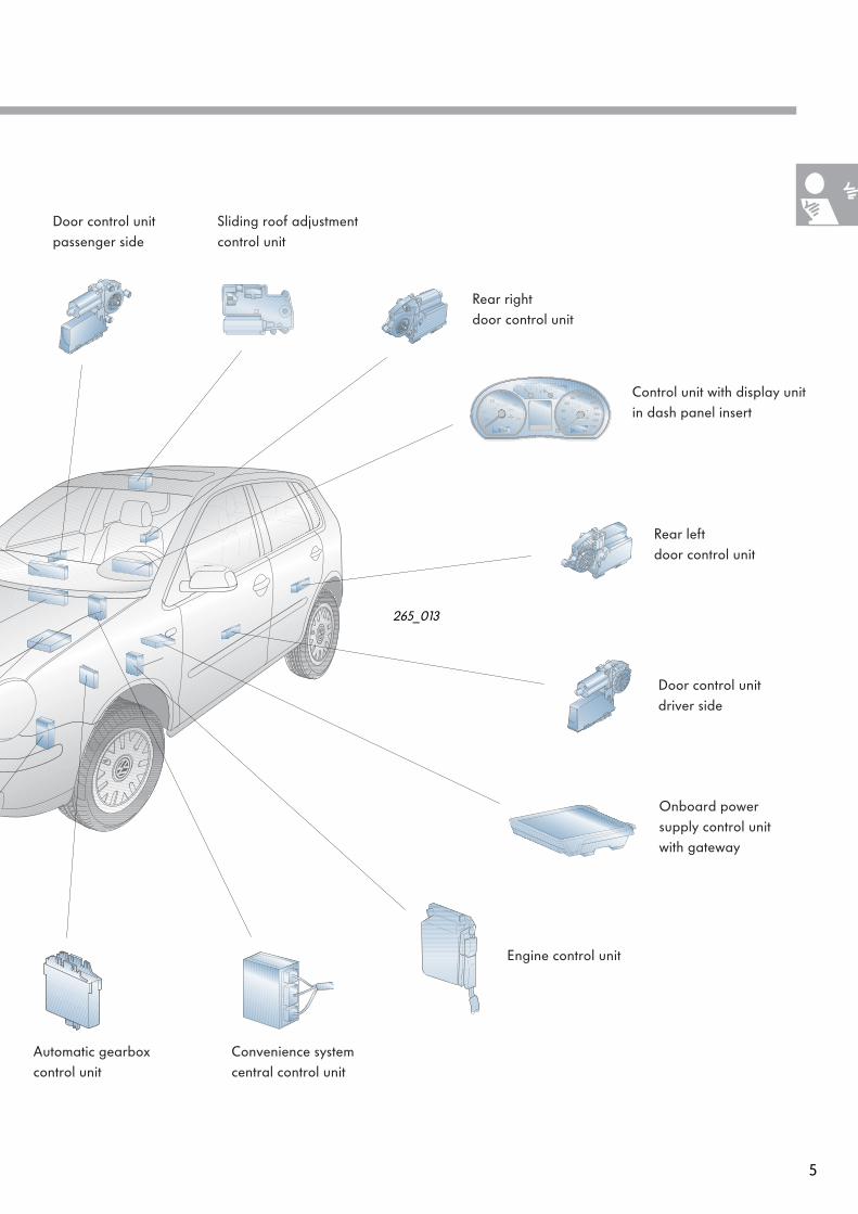
5
Rear left door control unit
Convenience system central control unit
Onboard power supply control unit with gateway
Door control unit driver side
Rear right door control unit
Sliding roof adjustment control unit
265_013
Control unit with display unit in dash panel insert
Engine control unit
Automatic gearbox control unit
Door control unitpassenger side

6
Onboard power supply
Onboard power supply
The onboard power supply is a decentralized design. The most important stations are:
Coupling stations in A-pillar and B-pillar
265_011
265_008
265_007265_006
265_009
L K I H D C B A
P N M G F E
Onboard power supply control unit
Main fuse carrier
Fuse holder
Compact connector
Relay carrier
1 2 3
5 6 7 8 9
11 12 13 14 15
4
10
265_021
265_012
265_005
265_010
Voltage distributor

7
265_009
Main fuse carrier
The main fuse carrier is located on battery cover.
The number of fuses always depends on the equipment fitted to the particular model.
The main fuse carrier houses up to 6 strip fuses and 10 plug-in fuses. A voltage cable provides the connection to the battery (positive). The fuses protect the individual power circuits immediately downstream of the battery from overloads.
Voltage distributor
The voltage distributor is located on the driver side behind the dash panel cover.
The voltage distributor is responsible for distribu-ting the current of terminal +30 from the main fuse carrier on the battery to the individual elec-trical components.
265_010

8
Onboard power supply
Fuse holder
The fuse holder is located behind the cover in the left side of the dash panel.
There are two types of fuses for protecting the power circuits:
– Mini-fuses up to 15 A– Little fuses more than 15 A
This combination offers the following advan-tages:
– greater number of fuses within the same space
– greater number of individually protected cir-cuits
These fuses are identified in the current flow diagram with the abbreviated designation „SB“.
Relay carrier
The relay carrier is located on the driver side behind the dash panel cover.
Compared to the design consisting of mini elec-trical centre and additional relay carrier, the relay carrier of the Polo is a single component with standardized design for accommodating the relays.
1 2 3
5 6 7 8 9
11 12 13 14 15
4
10
Position Relay
1 Not assigned
2 Motronic power supply relay
3 Glow plug relay
4 Fuel pump relay(diesel engines)
5 Entry warning light relay
6 Headlight washer system relay
7 Starter lockout relay
8 Low heating capacity relay
9 High heating capacity relay
10 Simos control unit power supply relay
11 Relief relay for X contact
12 Fuel supply relay
13 Fuel pump relay(petrol engines)
14 Fuse carrier for electric auxiliary heater
15 Diesel direct injection system relay
265_021
265_008
Mini-fuse
Little fuse

9
Coupling stations
The purpose of the coupling stations is to link the electrical components in the doors to the rest of the onboard power supply.
The coupling stations permit:
– easy access– separation of the wiring looms to the doors– simplified fault finding
A-pillar coupling station:
It is located close to the top door hinge at the A-pillar.
This coupling station combines the plug connec-tions to the following electrical components in the doors:
– loudspeaker– exterior mirror– lock unit– warning light
B-pillar coupling station:
It is located close to the top door hinge of the rear door at the B-pillar.
This coupling station combines the plug connec-tions to the following electrical components in the doors:
– loudspeaker– lock unit
265_006
265_007

10
Onboard power supply
Compact connector
The compact connector links the part of the onboard power supply in the engine compart-ment to the part of the onboard power supply in the interior.
The onboard power supply is designed in such a way that all the cables of the components or the two wiring looms (engine compartment, interior) merge in their individual connectors of the modules on the relevant side of the compact connector.
The connection is created by means of the indivi-dual connectors of the modules, irrespective of the equipment or version variants.
The connector provides a straightforward means of separating the onboard power supply at this point.This greatly facilitates test operations as well as removal and installation work.
Middle part of dash panel
Bulkhead Coupling stations
Roof module
Battery Compact connector
Fuse carrier
Coupling station
Coupling connector
265_022
Coupling connector
11
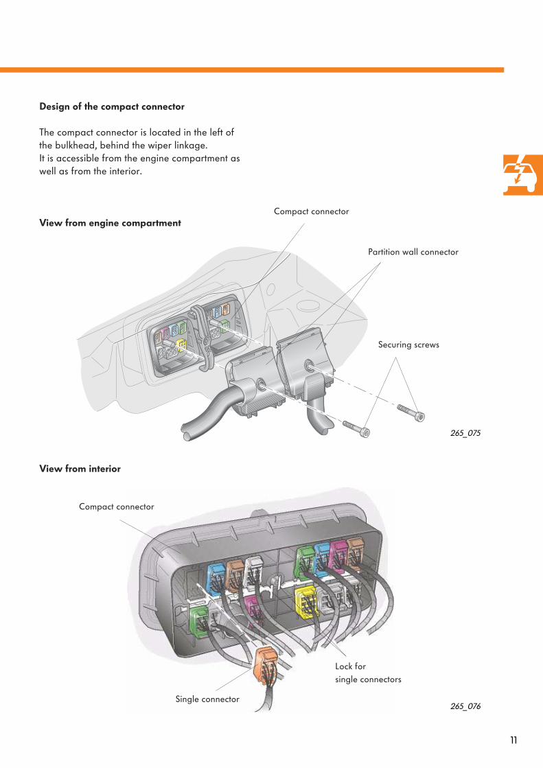
Design of the compact connector
The compact connector is located in the left of the bulkhead, behind the wiper linkage.It is accessible from the engine compartment as well as from the interior.
View from engine compartment
View from interior
Compact connector
265_075
Partition wall connector
Securing screws
265_076
Compact connector
Single connector
Lock forsingle connectors

12
Onboard power supply
265_005
The compact connector is subdivided into various modules. The connections are created by means of mechanically coded connectors of dif-ferent colours for the individual modules.
Compact connectorView from engine
compartment
L K I H D C B A
P N M G F E
Connector assignment
Module Responsible for Module Responsible for
A ABS, ESP H Not assigned
B Gearbox, engine, K wire,clutch pedal switch
I Additional heater, accelerator pedal position sender, brake pedal switch
C Engine power supply K Engine, dash panel insert
D Light, cruise control system, drivetrain CAN databus
L AC, radiator fan control
E Anti-theft alarm system M ABS, ESP
F Battery +30 N Diesel glow plug system
G Dash panel insert P Windscreen wash and wipe system
13
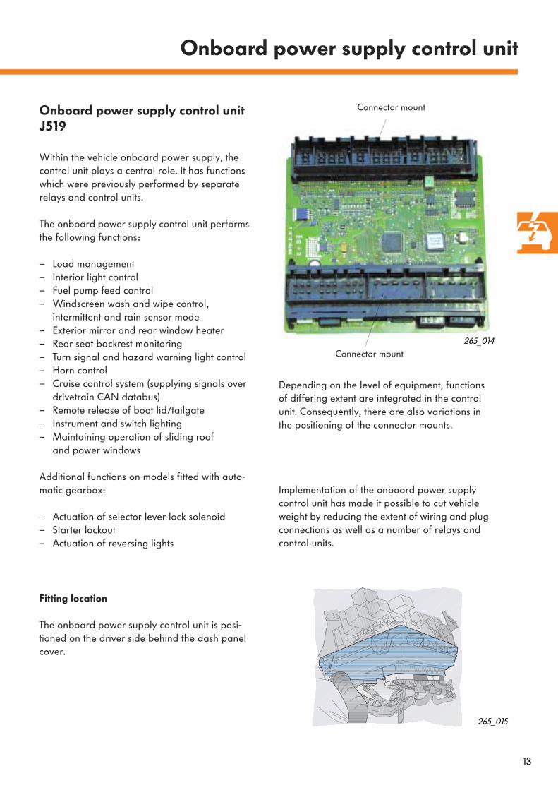
Onboard power supply control unit J519
Within the vehicle onboard power supply, the control unit plays a central role. It has functions which were previously performed by separate relays and control units.
The onboard power supply control unit performs the following functions:
– Load management– Interior light control– Fuel pump feed control– Windscreen wash and wipe control,
intermittent and rain sensor mode– Exterior mirror and rear window heater– Rear seat backrest monitoring– Turn signal and hazard warning light control– Horn control– Cruise control system (supplying signals over
drivetrain CAN databus)– Remote release of boot lid/tailgate– Instrument and switch lighting– Maintaining operation of sliding roof
and power windows
Additional functions on models fitted with auto-matic gearbox:
– Actuation of selector lever lock solenoid– Starter lockout– Actuation of reversing lights
Onboard power supply control unit
265_014
Depending on the level of equipment, functions of differing extent are integrated in the control unit. Consequently, there are also variations in the positioning of the connector mounts.
265_015
Fitting location
The onboard power supply control unit is posi-tioned on the driver side behind the dash panel cover.
Connector mount
Connector mount
Implementation of the onboard power supply control unit has made it possible to cut vehicle weight by reducing the extent of wiring and plug connections as well as a number of relays and control units.

14
Load management
The wide range of convenience functions and electrically heated components such as seat hea-ter, rear window heater, exterior mirror heaters and electric auxiliary heater (heating element for auxiliary heater Z35) can result in an overload of the alternator when driving and thus in a drain on the battery.
This is particularly the case when driving extre-mely short distances and in winter as well as stop- and go journeys and vehicles with a high level of equipment.
Onboard power supply control unit
The load management of the onboard power supply control unit regularly monitors the battery voltage, while taking into account the power demand of short-term consumers.
If it detects a voltage deficit in the onboard power supply, the control unit initiates measures to maintain vehicle operation and to ensure that the vehicle can be restarted.
265_046
Electrical circuit
A BatteryC AlternatorJ... Engine control unitJ131 Heated driver seat control unitJ132 Heated passenger seat
control unitJ255 CLIMAtronic control unitJ301 AC control unitJ519 Onboard power supply control unitJ533 Databus diagnostic interfaceZ1 Heated rear windowZ4 Heated exterior mirror,
driver sideZ5 Heated exterior mirror,
passenger sideZ6 Heated driver seatZ7 Heated driver backrestZ8 Heated passenger seatZ9 Heated passenger backrest
J131 J132
G C
J519
A
Z1 Z4 Z5
Z6 Z7
J255/J301
Z8 Z9
J ...
J533

15
Idling speed is increased if onboardonboard power supply voltage drops below 12.7 V. If voltage drops below 12.2 V, onboard power supply control unit additionally switches off the following components:
If specified voltage is again reached, onboard power supply control unit takes the following measures:
1 5
2 4
3 3
4 2
5AC
AC
1
Increases idling speed
Switches off rear window heater
Switches off seat heaters
Switches off exterior mirror heaters
Reduces AC compressor capacity
Reduces idling speed
Switches on rear window heater
Switches on seat heaters
Switches on exterior mirror heaters
Increases AC compressor capacity
16
Onboard power supply control unit
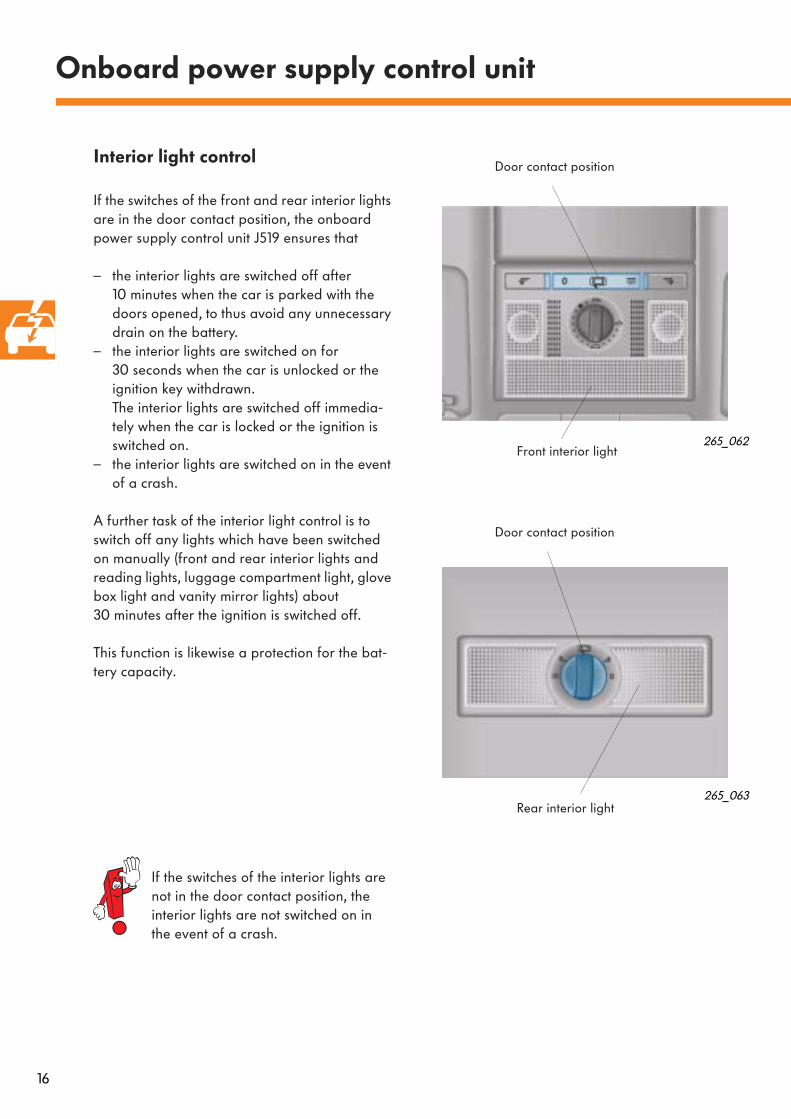
Interior light control
If the switches of the front and rear interior lights are in the door contact position, the onboard power supply control unit J519 ensures that
– the interior lights are switched off after 10 minutes when the car is parked with the doors opened, to thus avoid any unnecessary drain on the battery.
– the interior lights are switched on for 30 seconds when the car is unlocked or the ignition key withdrawn. The interior lights are switched off immedia-tely when the car is locked or the ignition is switched on.
– the interior lights are switched on in the event of a crash.
A further task of the interior light control is to switch off any lights which have been switched on manually (front and rear interior lights and reading lights, luggage compartment light, glove box light and vanity mirror lights) about 30 minutes after the ignition is switched off.
This function is likewise a protection for the bat-tery capacity.
Front interior light
Door contact position
If the switches of the interior lights are not in the door contact position, the interior lights are not switched on in the event of a crash.
Rear interior light
Door contact position
265_062
265_063

17
J519 Onboard power supply control unitW Front interior lightW6 Glove box lightW13 Reading light passenger sideW14 Illuminated vanity mirror
(passenger side)W18 Left luggage compartment lightW19 Reading light driver sideW20 Illuminated vanity mirror
(driver side)W43 Rear interior light
* on models not fitted with central locking** on models fitted with central locking
265_059
Electrical circuit
CAN-A Drivetrain CAN databusCAN-K Convenience CAN databusD Ignition/start switchF2 Door contact switch, driver sideF3 Door contact switch, passenger sideF10 Left rear door contact switchF11 Right rear door contact switchF220 Central locking lock unit,
driver sideF221 Central locking lock unit,
passenger sideF222 Central locking lock unit,
rear leftF223 Central locking lock unit,
rear right
J519
+30F2*F220** +15
W20 W14 W19 W W13W6 W43
F3*F221**
F10*F222**
F11*F223** CAN-K CAN-AD
W18
18
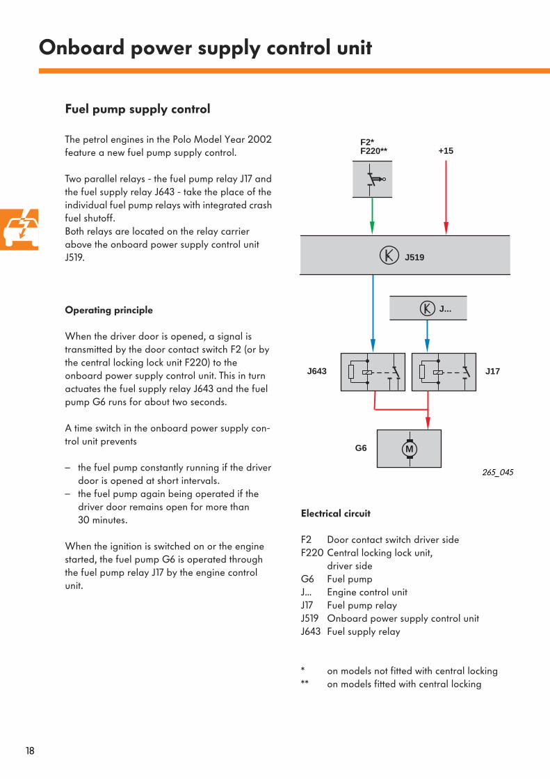
Fuel pump supply control
The petrol engines in the Polo Model Year 2002 feature a new fuel pump supply control.
Two parallel relays - the fuel pump relay J17 and the fuel supply relay J643 - take the place of the individual fuel pump relays with integrated crash fuel shutoff.Both relays are located on the relay carrier above the onboard power supply control unit J519.
Operating principle
When the driver door is opened, a signal is transmitted by the door contact switch F2 (or by the central locking lock unit F220) to the onboard power supply control unit. This in turn actuates the fuel supply relay J643 and the fuel pump G6 runs for about two seconds.
A time switch in the onboard power supply con-trol unit prevents
– the fuel pump constantly running if the driver door is opened at short intervals.
– the fuel pump again being operated if the driver door remains open for more than 30 minutes.
When the ignition is switched on or the engine started, the fuel pump G6 is operated through the fuel pump relay J17 by the engine control unit.
Electrical circuit
F2 Door contact switch driver sideF220 Central locking lock unit,
driver sideG6 Fuel pumpJ... Engine control unitJ17 Fuel pump relayJ519 Onboard power supply control unitJ643 Fuel supply relay
* on models not fitted with central locking** on models fitted with central locking
Onboard power supply control unit
J519
+15
J643
G6
F2*F220**
J...
M
J17
265_045

19
F266
V
J519
E22
M
Activating rear screen wiper
When reverse gear is engaged, the rear screen wiper automatically makes a single sweep.The following conditions must be met for this pur-pose:
– windscreen wiper switched on with stage 1 or 2or
– intermittent wipe (speed-responsive intermit-tent mode or rain sensor mode) switched on
Electrical circuit
E22 Intermittent wiper switchF4 Reversing light switchJ519 Onboard power supply control unitV Windscreen wiper motorV12 Rear screen wiper motor
Blocking windscreen wipers
If the windscreen wipers are operating in the intermittent wipe mode (speed-responsive inter-mittent mode or rain sensor mode) and at the same time the bonnet is opened, a signal is transmitted by the bonnet contact switch F266 to the onboard power supply control unit. The control unit blocks the movement of the windscreen wipers until the bonnet is again closed.This function is intended as a safety measure when carrying out work on the car.
Electrical circuit
E22 Intermittent wiper switchF266 Bonnet contact switchJ519 Onboard power supply control unitV Windscreen wiper motor
265_038
F4 E22 V
V12
J519
M
M
265_037
20
Onboard power supply control unit
J519
F316 +15
K
J285
K193
CAN-K
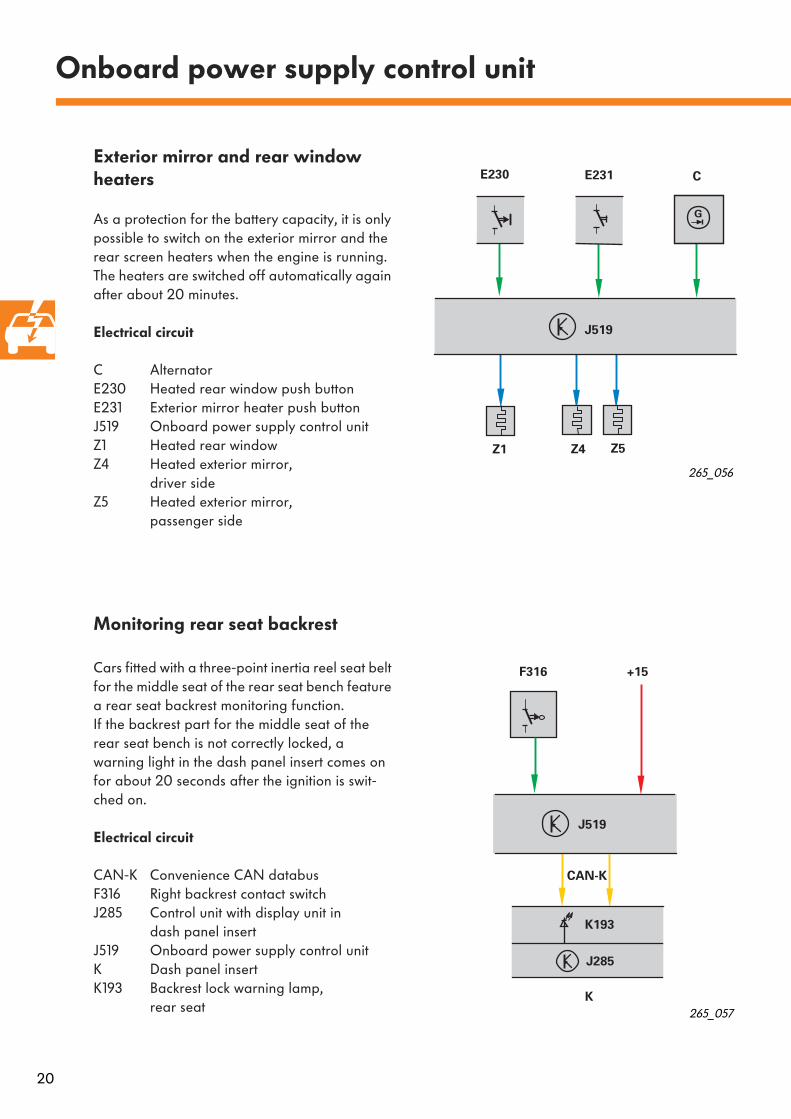
Exterior mirror and rear window heaters
As a protection for the battery capacity, it is only possible to switch on the exterior mirror and the rear screen heaters when the engine is running.The heaters are switched off automatically again after about 20 minutes.
Electrical circuit
C AlternatorE230 Heated rear window push buttonE231 Exterior mirror heater push buttonJ519 Onboard power supply control unitZ1 Heated rear windowZ4 Heated exterior mirror,
driver sideZ5 Heated exterior mirror,
passenger side
Monitoring rear seat backrest
Cars fitted with a three-point inertia reel seat belt for the middle seat of the rear seat bench feature a rear seat backrest monitoring function.If the backrest part for the middle seat of the rear seat bench is not correctly locked, a warning light in the dash panel insert comes on for about 20 seconds after the ignition is swit-ched on.
Electrical circuit
CAN-K Convenience CAN databusF316 Right backrest contact switchJ285 Control unit with display unit in
dash panel insertJ519 Onboard power supply control unitK Dash panel insertK193 Backrest lock warning lamp,
rear seat
265_057
265_056
J519
E231E230
Z1 Z4 Z5
G
C
21
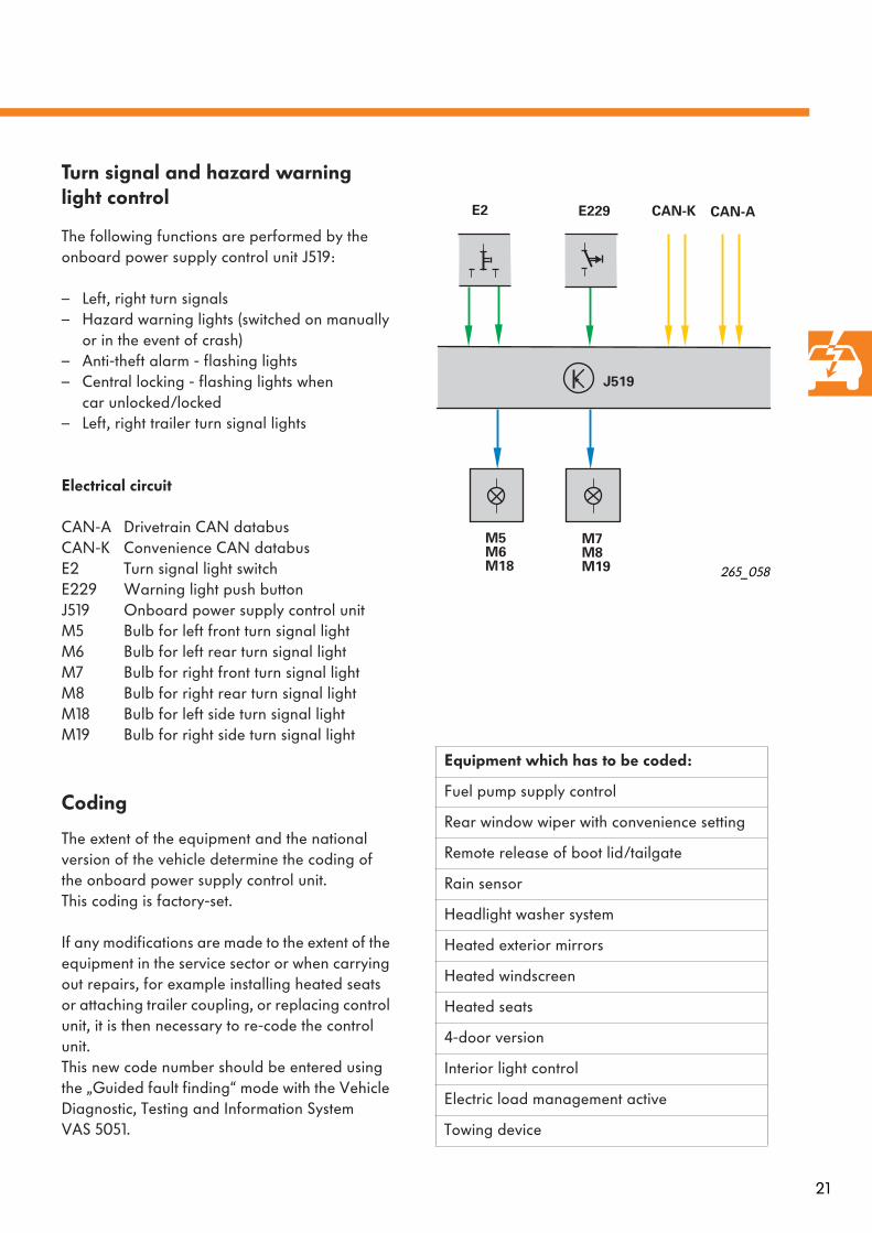
Turn signal and hazard warning light control
The following functions are performed by the onboard power supply control unit J519:
– Left, right turn signals– Hazard warning lights (switched on manually
or in the event of crash)– Anti-theft alarm - flashing lights– Central locking - flashing lights when
car unlocked/locked– Left, right trailer turn signal lights
Electrical circuit
CAN-A Drivetrain CAN databusCAN-K Convenience CAN databusE2 Turn signal light switchE229 Warning light push buttonJ519 Onboard power supply control unitM5 Bulb for left front turn signal lightM6 Bulb for left rear turn signal lightM7 Bulb for right front turn signal lightM8 Bulb for right rear turn signal lightM18 Bulb for left side turn signal lightM19 Bulb for right side turn signal light
Coding
The extent of the equipment and the national version of the vehicle determine the coding of the onboard power supply control unit. This coding is factory-set.
If any modifications are made to the extent of the equipment in the service sector or when carrying out repairs, for example installing heated seats or attaching trailer coupling, or replacing control unit, it is then necessary to re-code the control unit. This new code number should be entered using the „Guided fault finding“ mode with the Vehicle Diagnostic, Testing and Information System VAS 5051.
J519
E229E2 CAN-K
M5M6M18
CAN-A
M7M8M19
265_058
Equipment which has to be coded:
Fuel pump supply control
Rear window wiper with convenience setting
Remote release of boot lid/tailgate
Rain sensor
Headlight washer system
Heated exterior mirrors
Heated windscreen
Heated seats
4-door version
Interior light control
Electric load management active
Towing device

M
31
+15
+30
D/50
E2/R
J39
E1/SRA
G213 Y7
E2/LD/86s
D/75
M M
J519
31
BJ207*
ST
+
-
A
F4**
C/L
H H1
E38
E34
VZ1E230 K10
V5
E229 L76
M5 M18 M6 M7 M19 M8
V12
E22
L76
V11
J59
F266
F2 F3 F10 F11
1
M M
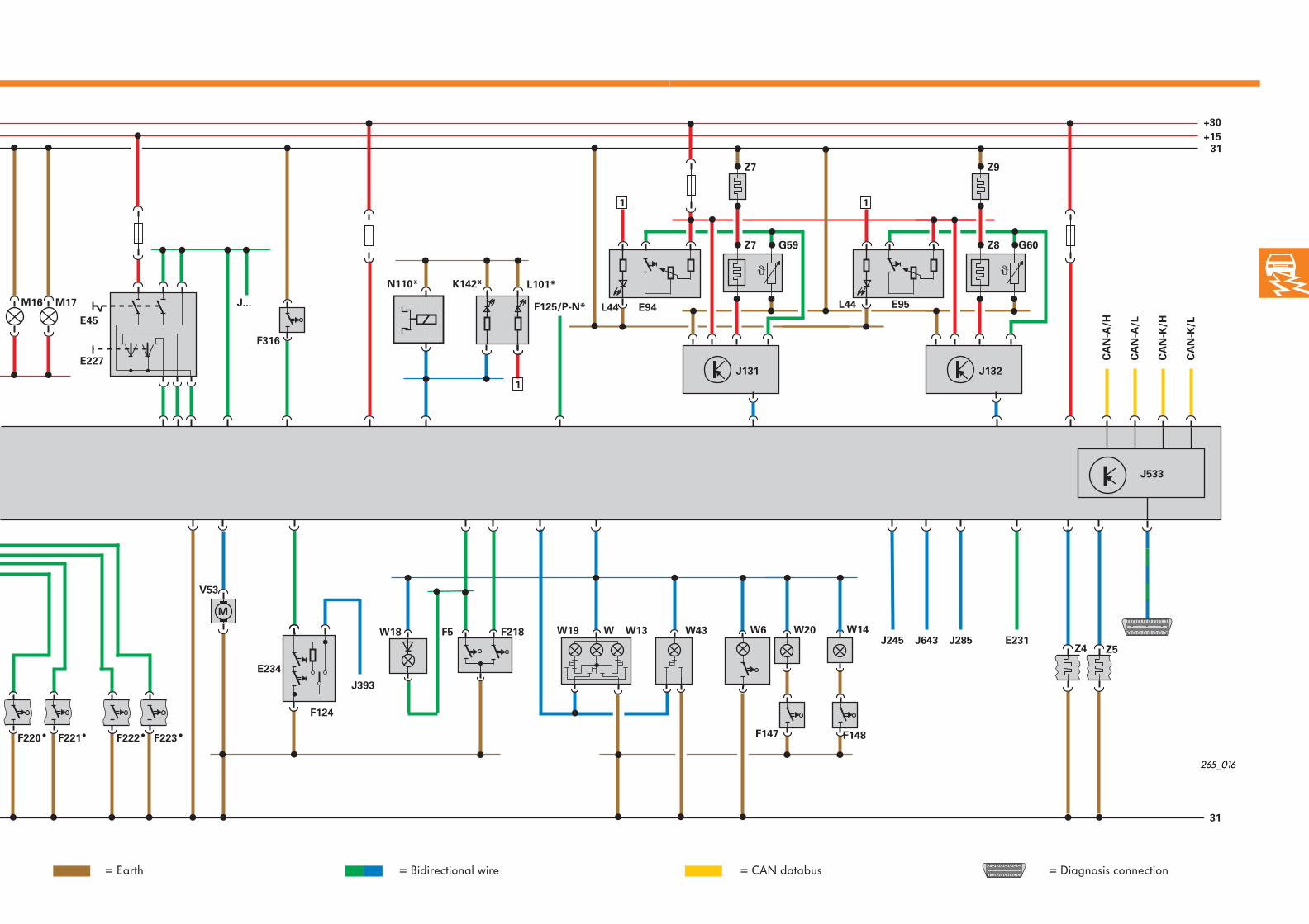
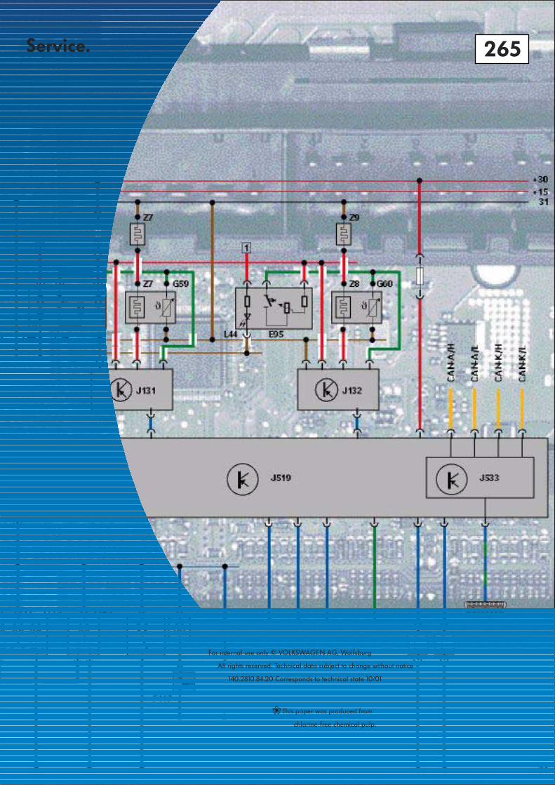
Onboard power supply control unit
Legend
A BatteryB StarterC/L Alternator/terminal LCAN-A/H Drivetrain CAN/HighCAN-A/L Drivetrain CAN/LowCAN-K/H Convenience CAN/HighCAN-A/L Convenience CAN/LowD/50 Ignition/starter switch/terminal 50D/75 Ignition/starter switch/terminal 75D/86s Ignition/starter switch/terminal 86sE1/SRA Light switch/terminal HWSE2/L,R Turn signal switch/positive connection left,
right turn signalE22 Intermittent wiper switchE34 Rear wiper switchE38 Intermittent wiper controlE45 CCS switchE94 Heated driver seat adjusterE95 Heated front passenger seat adjusterE227 CCS button (set)E229 Hazard warning lights buttonE230 Heated rear window buttonE231 Exterior mirror heating buttonE234 Tailgate/boot lid handle release buttonF2 Door contact switch - driver sideF3 Door contact switch - front passenger sideF4 Reversing light switchF5 Luggage compartment light switchF10 Rear left door contact switchF11 Rear right door contact switch F124 Contact switch in lock cylinder for tailgate/
boot lid anti-theft alarm system/central locking system
F125/P-N Multifunction switch/terminal P-NF147 Vanity mirror contact switch,
driver sideF148 Vanity mirror contact switch,
front passenger sideF218 Tailgate/boot lid central locking switchF220 Central locking lock unit,
driver sideF221 Central locking lock unit,
front passenger sideF222 Central locking lock unit,
rear leftF223 Central locking lock unit,
rear rightF266 Bonnet contact switchF316 Right backrest contact switchG59 Driver seat temperature sensorG60 Front passenger seat temperature sensorG213 Rain sensorH Horn plateH1 Horn J... Engine control unit
J17 Fuel pump relayJ39 Headlight washer system relayJ59 X contact relief relayJ131 Heated driver seat control unitJ132 Heated front passenger seat control unitJ207 Starter inhibitor relayJ245 Sliding roof adjustment control unitJ285 Control unit with display in
dash panel insertJ393 Convenience system central control unitJ519 Onboard power supply control unitJ533 Databus diagnostic interfaceJ643 Fuel supply relayK10 Heated rear window warning lampK142 Selector lever position P/N warning lampL44 Seat heating switch light bulbL76 Button illuminationL101 Selector lever display illuminationM5 Front left turn signal light bulbM6 Rear left turn signal light bulbM7 Front right turn signal light bulbM8 Rear right turn signal light bulbM16 Left reversing light bulbM17 Right reversing light bulbM18 Left side turn signal light bulbM19 Right side turn signal light bulbN110 Selector lever lock solenoidST Fuse carrier on batteryV Windscreen wiper motorV5 Windscreen washer pumpV11 Headlight washer system pumpV12 Rear window wiper motorV53 Central locking motor - tailgate/boot lidW Front interior lightW6 Glove box lightW13 Front passenger reading lightW14 Illuminated vanity mirror - front passenger sideW18 Left luggage compartment lightW19 Reading lamp - driver sideW20 Illuminated vanity mirror - driver sideW43 Rear interior lightY7 Automatic anti-dazzle interior mirrorZ1 Heated rear windowZ4 Heated exterior mirror, driver sideZ5 Heated exterior mirror, front passenger sideZ6 Heated driver seat cushionZ7 Heated driver seat backrestZ8 Heated front passenger seat cushionZ9 Heated front passenger seat backrest
* On models fitted with automatic gearbox** On models not fitted with automatic gearbox• On models fitted with central locking•• On models not fitted with central locking
= Input signal = Positive= Output signal
Function diagram
22
1
F222 F223
M
V53
E234
J393
W18 W19 W6 W20 W14
F148F147
J245W
1
Z4 Z5
J533
CA
N-A
/H
CA
N-A
/L
CA
N-K
/H
CA
N-K
/L
J643W13F5 F218
J285 E231
F220 F221
W43
F124
Z7
Z7
1
Z9
Z8G59 G60
J...
E45
E227
L44F125/P-N*
J131
L44
J132
E94 E95
+30
+1531
31
F316
M16 M17
N110* K142* L101*
= Earth = CAN databus= Bidirectional wire = Diagnosis connection
265_016

24
CAN databus
The drivetrain CAN databus operates with a transmission rate of 500 kBit/s in order to achieve rapid data transfer within the safety-relevant systems.
Drivetrain CAN databus
The Polo features a CAN databus system, consi-sting of the drivetrain CAN databus and the con-venience CAN databus.They differ in terms of their transmission rate and their data content.
265_023
Onboard power supply controlunit J519 with databus diagnosticinterface J533 (gateway)
Control unit with display unit in dashpanel insert J285
ABS control unit J104
Automatic gearbox control unit J217 Power steering
control unit J500
Airbag control unit J234
Engine control unit J...
Diagnostic connectionSteering angle sender G85
25
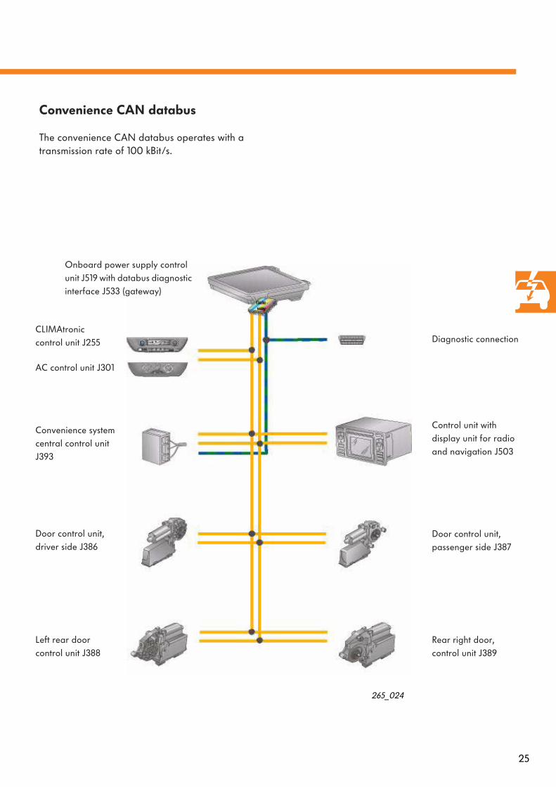
Convenience CAN databus
The convenience CAN databus operates with a transmission rate of 100 kBit/s.
265_024
Diagnostic connection
Onboard power supply control unit J519 with databus diagnostic interface J533 (gateway)
Control unit with display unit for radio and navigation J503
AC control unit J301
Door control unit,passenger side J387
Rear right door,control unit J389
Left rear doorcontrol unit J388
Door control unit,driver side J386
CLIMAtronic control unit J255
Convenience system central control unit J393

26
The databus diagnostic interface J533 (gateway) is integrated in the onboard power supply con-trol unit J519.
The databus diagnostic interface J533 performs 2 tasks:
1st task
It is responsible for the data transfer between the two CAN databus systems
– drivetrain CAN databus and– convenience CAN databus.
CAN databus
Databus diagnostic interface J533
265_018
Drivetrain CAN databus Convenience CAN databus
The gateway receives the data arriving from a BUS system and relays the data to each other BUS system.
Databus diagnostic interface J533
Gateway
265_065
Direct communication between the systems is not possible because of the different transmission rates.A link is required for exchanging information between the systems.This link is achieved by means of the databus diagnostic interface J533.
27
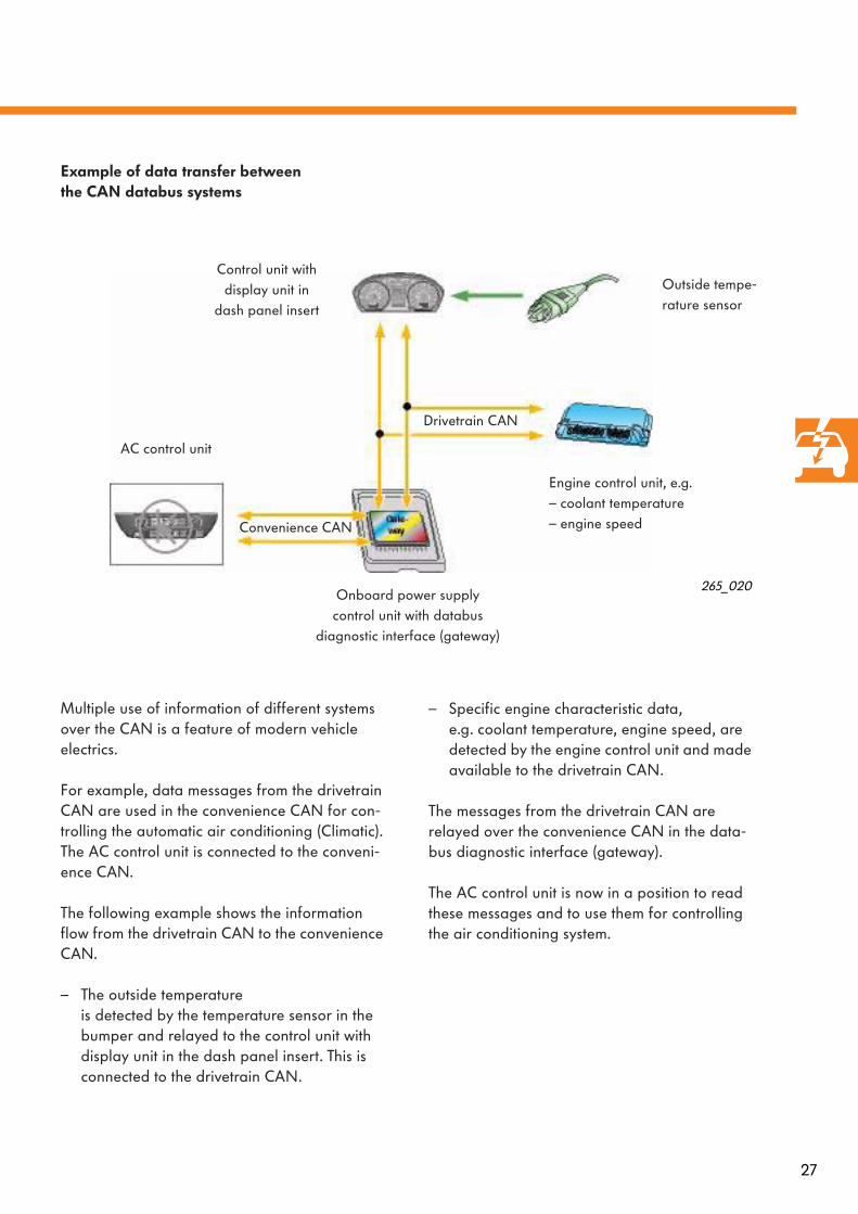
Example of data transfer betweenthe CAN databus systems
Multiple use of information of different systems over the CAN is a feature of modern vehicle electrics.
For example, data messages from the drivetrain CAN are used in the convenience CAN for con-trolling the automatic air conditioning (Climatic). The AC control unit is connected to the conveni-ence CAN.
The following example shows the information flow from the drivetrain CAN to the convenience CAN.
– The outside temperature is detected by the temperature sensor in the bumper and relayed to the control unit with display unit in the dash panel insert. This is connected to the drivetrain CAN.
– Specific engine characteristic data,e.g. coolant temperature, engine speed, are detected by the engine control unit and made available to the drivetrain CAN.
The messages from the drivetrain CAN are relayed over the convenience CAN in the data-bus diagnostic interface (gateway).
The AC control unit is now in a position to read these messages and to use them for controlling the air conditioning system.
265_020
AC control unit
Onboard power supply control unit with databus
diagnostic interface (gateway)
Engine control unit, e.g.– coolant temperature– engine speed
Outside tempe-rature sensor
Control unit with display unit in
dash panel insert
Drivetrain CAN
Convenience CAN

28
CAN databus
+30 -31
2nd task
The databus diagnostic interface J533 receives diagnostic data from the drivetrain CAN data-bus and from the convenience CAN databus and relays it over the K wire, and vice versa. This makes it possible to use data from the Vehicle Diagnostic, Testing and Information System VAS 5051 for self-diagnosis.
The engine control unit, the automatic gearbox control unit and the convenience system central control unit have a separate K wire.
Diagnostic connection
Databus diagnostic interface J533
265_019
K wire
Drivetrain CAN databus
Convenience CAN databus
Engine control unit
Automatic gearbox control unit
Convenience system central control unit

29
Example for data exchangefor diagnosis
The following example shows the flow of infor-mation from the drivetrain CAN over the K wire.
– Because of a fault in the cable connection, the brake light switch does not supply any infor-mation to the ABS control unit.
– The ABS control unit is connected to the drivetrain CAN and thereupon sets a fault in its fault memory.
To enable the Vehicle Diagnostic, Testing and Information System VAS 5051 to process such diagnosis data, the databus diagnostic interface in the onboard power supply control unit relays the diagnostic information from the drivetrain CAN databus over the K wire. The data are not changed as a result of this; in other words, the information content transmitted over the K wire and the CAN databus is the same.
Gate- way
265_077
Onboard power supply control unit with databus
diagnostic interface (gateway)
Brake light switch
ABS control unit
Diagnostic connection
K wire
Dri
vetr
ain
CA
N

30
M
Special functions
Special functions in the event of a crash
The safety system of the Polo features automatic circuits which, in the event of a crash, contribute to minimizing the severity of an emergency situa-tion.
The following actions are set in motion:
– central locking system is unlocked– interior lights are switched on– hazard warning lights system is switched on– fuel supply is interrupted
265_039
Airbag control unitEngine control unit
Onboard power supply control unit with integrated databus diagnostic interface (gateway)
Conveniencesystem centralcontrol unit
Door con-trol unit
Fuel pump
Door con-trol unit
Fuelpumprelay
Operating principle
If the airbags are deployed in a crash, the air-bag control unit simultaneously transmits a crash signal over the drivetrain CAN.This signal causes the engine control unit to switch off the fuel supply through the fuel pump relay.
The crash signal is relayed over the databus dia-gnostic interface (gateway) to the convenience CAN and the convenience system central control unit thereupon unlocks all the doors. In addition, the onboard power supply control unit switches on the interior lights (if the switches are in the door contact position) and also the hazard warning lights.

31
Energy saving functions
Sleep mode
To minimize current consumption when the igni-tion is switched off, the control units which are connected to the CAN databus are switched into a sleep mode.
In the case of the drivetrain CAN databus, this is the normal situation after the ignition is switched off as data only require to be transmitted in the drivetrain CAN databus if the ignition is on.In the case of the convenience CAN databus, the sleep mode is activated after the ignition is switched off and provided the following conditi-ons exist:
– hazard warning light system off– function retention elapsed– no transfer of diagnostic data– exterior lights off
Electrical circuit
J285 Control unit with display unit in dashpanel insert
J519 Onboard power supply control unitJ533 Databus diagnostic interface
= CAN databus
= Wake-up cable
Wake-up mode
In the event that the control unit detects a wake-up command resulting from one of the actions listed below, it relays this to the other control units so that these control units are also activa-ted.
In the case of the drivetrain CAN databus, the wake-up command is always relayed after the ignition is switched on.In the case of the convenience CAN databus, the wake-up command is transmitted after the follo-wing actions:
– ignition switched on– hazard warning light system active– change in status of doors, tailgate, bonnet
and ignition lock– exterior lights on
265_017
Exception:The control unit with display unit in the dash panel insert, which is connected to the drivetrain CAN databus, also requires data from the convenience CAN databus even when no supply voltage is present (ignition off). For this reason, either a direct convenience CAN connection or a cable connection (wake-up cable) to the onboard power supply control unit is required.This depends on the equipment version of the dash panel insert.
J533J519
J285Drivetrain CAN databus
Convenience CAN databus

32
Convenience and safety electronics
The convenience system
is a decentralized design. It consists of a central control unit and at least 2 door control units.
– Central locking of rear lock
– Convenience closing functions(power windows, sliding roof)
– Single door opening of driver door
– Central locking of doors
– Unlocking and locking of complete vehiclewith interior push button (Lock-Unlock)
– Anti-theft alarm system which can be deactivated only with remote control
– Ultrasound interior monitoring with deactivate function
– Self-diagnosis
– Actuation of central locking warning lamp -SAFE-
– Electrically adjustable exterior mirrors withfold-in function
– Power windows with excess force limiterand with gentle opening/closing to minimize noise
Functions of the door control units
Functions of the central control unit
You can obtain further information on the interactions of the convenience system in Self-Study Programme 193. Only supplementary details are pre-sented here.

33
H
J
J519
R
G
F
F
F
G
F
A
E
A
B
C
D
M
M
E
A M
E
B
A M
CA
N
CAN CAN
CA
N
CA
N
J393
G
K
S
M
N
L
T
Overview of convenience system (schematic diagram)
J393 Convenience system central control unitJ519 Onboard power supply control unitA Door control unitB Electrically adjustable rear-view mirrorC Mirror and heater adjustment switchD Driver door operating panelE Power window switchF Central locking door lockG Entry warning lampH Tailgate/boot lid rotary tumbler switch
J Tailgate push buttonK Central locking warning lamp
-SAFE-L Interior monitor sensor
unitM Interior monitor push buttonN Alarm hornR Relay for warning lights, doorsS Remote controlT Sliding roof adjustment control unit
Driver door Front passenger door
Diagnostic connection
Right reardoor
Left rear door
Tailgate/boot lid265_025
Coupling station

34
Remote control
Remote release of tailgate/boot lid
Models fitted with a remote control feature an additional push button for separate remote release of the tailgate/boot lid.
If the remote release push button is pressed, only the tailgate/boot lid is unlocked. If the tailgate/boot lid is not opened within two minutes, it is automatically relocked.
This function is coded in the onboard power sup-ply control unit (refer also to Onboard power supply control unit page 21).
Single door opening of driver door
This function is intended for personal safety. If the remote control Unlock button is pressed briefly only once, only the driver door is unlok-ked. This is indicated by all the turn signal lights flashing briefly.
If the Unlock button is pressed a second time, all the locks of the car are unlocked.
If the car has been completely unlocked and no door or boot lid/tailgate is opened within 30 seconds, the car is locked again.This prevents the car being left unlocked uninten-tionally for a lengthy period.This option is coded in the convenience system central control unit in the delivery state of the vehicle in conformity with the vehicle equipment.
Convenience and safety electronics
265_052
Remote releasebutton for tailgate/boot lid
Unlock button
265_066

35
Anti-theft alarm with interiormonitoring
The anti-theft alarm
monitors the following areas
– doors,– bonnet,– boot lid/tailgate and– ignition
for unauthorized opening or operation.
Sensor unit
Alarm horn withintegrated battery
Convenience systemcentral control unit
Interior monitoring
operates as an ultrasound monitoring system and is used only in combination with the anti-theft alarm.This system additionally monitors the interior of the car for any unauthorized attempt to enter the car.
An audible alarm is provided by the alarm horn of the anti-theft system and a visual alarm by the turn signal lights.
The system is safe against false alarm resulting from:
– knocking on the car roof or against the win-dows,
– movements of air caused by wind or vehicles passing, temperature changes such as interior of car heating up as a result of extreme sunl-light penetration and
– noises of any type (e.g. horns, sirens and bells).
Interior monitorpush button
265_064
36
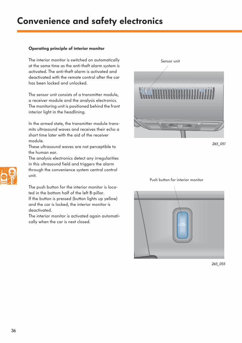
Operating principle of interior monitor
The interior monitor is switched on automatically at the same time as the anti-theft alarm system is activated. The anti-theft alarm is activated and deactivated with the remote control after the car has been locked and unlocked.
The sensor unit consists of a transmitter module, a receiver module and the analysis electronics. The monitoring unit is positioned behind the front interior light in the headlining.
In the armed state, the transmitter module trans-mits ultrasound waves and receives their echo a short time later with the aid of the receiver module.These ultrasound waves are not perceptible to the human ear.The analysis electronics detect any irregularities in this ultrasound field and triggers the alarm through the convenience system central control unit.
The push button for the interior monitor is loca-ted in the bottom half of the left B-pillar.If the button is pressed (button lights up yellow) and the car is locked, the interior monitor is deactivated. The interior monitor is activated again automati-cally when the car is next closed.
Convenience and safety electronics
265_051
265_055
Sensor unit
Push button for interior monitor

37
Comfort position
The sliding roof features a comfort position. If the sliding roof adjustment switch in the front interior light is turned into this position, the sliding roof is not opened fully. Consequently, there is scarcely any wind noise inside the car when travelling at higher speeds with the roof set in this position.
The sliding/tilting roof offers the following addi-tional functions:
– Closing the sliding/tilting roof as part of the convenience closing function by operating the central locking system
– Function maintained for 10 minutes after igni-tion is switched off provided none of the front doors is opened
– Force limit if the sliding/tilting roof is obstruc-ted because of difficult operation or because of an obstacle during the closing operation
Sliding/tilting roof
265_080
265_079
The sliding roof adjustment switch cannot be replaced separately in the event of a repair. It is then necessary to replace the complete interior light.
Comfort position
Comfort position
38
Dash panel insert
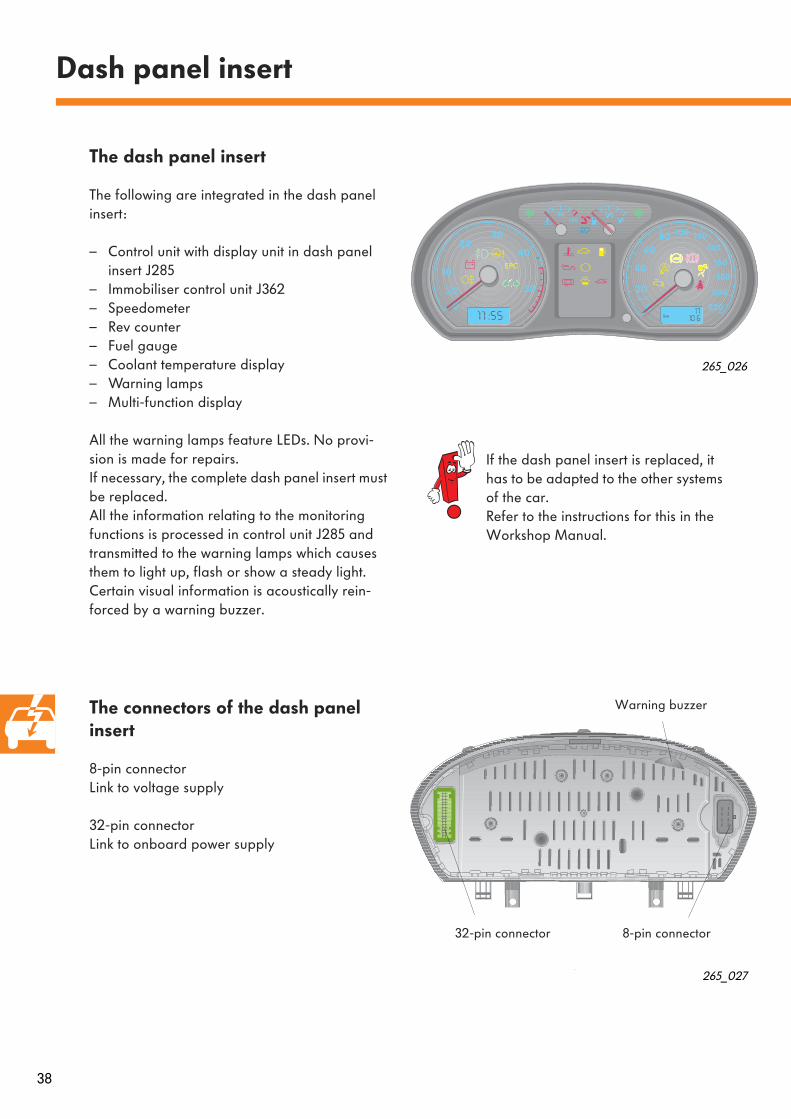
The dash panel insert
The following are integrated in the dash panel insert:
– Control unit with display unit in dash panel insert J285
– Immobiliser control unit J362– Speedometer– Rev counter– Fuel gauge– Coolant temperature display– Warning lamps– Multi-function display
All the warning lamps feature LEDs. No provi-sion is made for repairs. If necessary, the complete dash panel insert must be replaced.All the information relating to the monitoring functions is processed in control unit J285 and transmitted to the warning lamps which causes them to light up, flash or show a steady light. Certain visual information is acoustically rein-forced by a warning buzzer.
The connectors of the dash panel insert
8-pin connectorLink to voltage supply
32-pin connectorLink to onboard power supply
265_026
265_027
If the dash panel insert is replaced, it has to be adapted to the other systems of the car. Refer to the instructions for this in the Workshop Manual.
8-pin connector32-pin connector
Warning buzzer

39
Display symbols
The number and the location of the warning lamps depend on the model and engine version.Warning lamps which are fitted only to certain models are marked with (*).
Display symbol
Designation Type and meaning of indication
Fog lights come on when fog lights operating;switched on by pulling out light switch as far as first detent into side light or low beam position
The symbols are only visible when the correspon-ding LEDs behind them are illuminated.The ignition must be switched on for this purpose. The table presents new warning lamps which have been added in the Polo Model Year 2002.
265_028

40
Dash panel insert
Display symbol
Designation Type and meaning of indication
Electrically powered hydraulic steering
lights up for a short time after ignition switched on and goes out after engine started,lights up continuously if fault in steering system; car should be driven to nearest workshop
Engine oil level(too low)
Engine oil level(engine oil level sensorfaulty)
Engine oil pressure
lights up yellow if engine oil level is too low;check oil level and replenish if necessary;if bonnet remains open for more than 30 seconds, oil level warning is reset;if no oil has been replenished, warning is displayed again after about 100 km
flashes yellow, i.e. engine oil level sensor is faulty; audible signal sounds in addition;drive car to nearest workshop
flashes red, i.e. engine oil pressure is too low; in addition an audible signal sounds 3 times at engine speeds of more than 1500 rpm;stop; switch engine off!Check oil level and replenish if necessary;if warning lamp continues flashing although oil is at correct level - do not drive car any further!
Cruise control system lights up if cruise control system operating
Rear seat backrest lock lights up for about 20 seconds when ignition switched on if backrest of rear seat is not correctly locked;lights up and remains on if backrest is unlocked when driving
*
*
*
* Models fitted with optional equipment
*
*

41
*
*
*
*
Display symbol
Designation Type and meaning of indication
Electronic immobiliser lights up for about 3 seconds when ignition switched on; automatic scanning of data of car key performed during this time; if authorized key is detected, car can be started;an alarm activated by the anti-theft system is switched off;if a non-authorized key is detected, car cannot be started and the warning lamp switches to „continuous flashing mode“
Brake pad wear indicator lights up if minimum permissible brake pad thickness is reached;car must be driven to nearest workshop to have brake pads inspected or replaced
Washer fluid level lights up if insufficient fluid in windscreen washer reservoir;replenish windscreen washer fluid
Door open lights up if not all the doors are closed
Trailer turn signal system lights up if turn signal system switched on when towing a trailer.If a turn signal light at trailer or car is not operating, warning lamp does not flash.
* Models fitted with optional equipment

42
Lighting
265_029
265_030
Turn signal light(yellow bulb)
Brake light
Tail light/rear fog light
Reversing light
Main beam(H1 bulb)
Low beam(H7 bulb)
Turn signal light
Headlights
The new headlights are designed as a twin unit and feature clear plastic lenses for the light beams.
The headlight unit has two reflectors. The reflec-tor for main beam and side light is a single chamber, while the reflector for low beam and turn signal light is split into two chambers.
The bulb for the turn signal light is coloured yel-low. The light beam is produced by the respective shape of the reflector chamber.
The fog lights are integrated not in the headlight unit but in the bumper.
Rear light units
The reflector is a single unit and is divided into four main chambers; the chamber for the tail light/rear fog light is once again divided inter-nally. The upper half of the chamber includes a bulb for the tail light. The bottom half of the chamber includes a twin-filament bulb for the tail light/rear fog light.
When the lights are switched on, one filament of this twin-filament bulb is illuminated as a tail light together with the tail light in the top half of the chamber.This provides enhanced safety in the event of one of the tail lights not operating.When the rear fog light is switched on, the second filament of the twin-filament bulb is also illuminated.
Reflectors are integrated in the full area of the lens of the tail light cluster.
Tail light
Side light
43
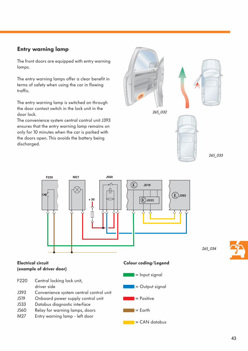
Entry warning lamp
The front doors are equipped with entry warning lamps.
The entry warning lamps offer a clear benefit in terms of safety when using the car in flowing traffic.
The entry warning lamp is switched on through the door contact switch in the lock unit in the door lock.The convenience system central control unit J393 ensures that the entry warning lamp remains on only for 10 minutes when the car is parked with the doors open. This avoids the battery being discharged.
265_032
Electrical circuit(example of driver door)
F220 Central locking lock unit,driver side
J393 Convenience system central control unitJ519 Onboard power supply control unitJ533 Databus diagnostic interfaceJ560 Relay for warning lamps, doorsM27 Entry warning lamp - left door
Colour coding/Legend
= Input signal
= Output signal
= Positive
= Earth
= CAN databus
J519
J393
M27 J560
30+
F220
J533
265_034
265_033
44
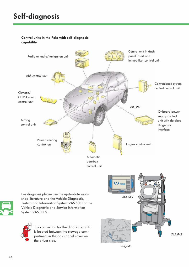
Control units in the Polo with self-diagnosis capability
Self-diagnosis
ABS control unit
Automatic gearboxcontrol unit
Airbag control unit
Power steering control unit
Control unit in dashpanel insert andimmobiliser control unit
Climatic/CLIMAtronic control unit
265_041
For diagnosis please use the up-to-date work-shop literature and the Vehicle Diagnostic, Testing and Information System VAS 5051 or the Vehicle Diagnostic and Service Information System VAS 5052.
265_042
Onboard power supply control unit with databus diagnostic interface
Convenience systemcentral control unit
Engine control unit
Radio or radio/navigation unit
IrDA + - VAS 5052
WOR KSH OPEQUIPMENTWOR KSH OPEQUIPMENT
265_054
265_043
The connection for the diagnostic units is located between the stowage com-partment in the dash panel cover on the driver side.

45
Notes

46
Test your knowledge
1. The onboard power supply control unit ...
A. replaces the convenience system central control unit.B. is the central monitoring and control unit of the onboard power supply.C. controls the power demand of the onboard power supply.
2. The databus diagnostic interface ...
A. transmits the diagnostic data of the K wire over the CAN and vice versa.B. monitors the function of the onboard power supply control unit.C. is the connection point of the CAN databus systems.
3. There are two CAN databus systems in the onboard power supply operating ...
A. each on their own.B. together through the connections of the compact connectors.C. together through the gateway in the onboard power supply control unit.
4. The tasks of the compact connector in the bulkhead consist of ...
A. connecting the „engine compartment“ and „interior“ sections of the wiring looms.B. facilitating service work.C. creating installation space.
5. The code numbers are ...
A. secret numbers for the operation of the immobiliser.B. count numbers transmitted to the control units.C. values for coding control units in accordance with the vehicle equipment.
Which answers are correct?Sometimes only one.But perhaps also more than one – or all of them!

47
6. The drivetrain CAN databus operates with...
A. a transmission rate of 500 kBit/s.B. a transmission rate of 100 kBit/s.C. a transmission rate of 50 kBit/s.
7. The wake-up function is designed to ...
A. wake up the driver out of the „sleep state“.B. wake up the control units connected to the CAN databus systems
out of the „sleep state“.C. control the fuel pump supply.
8. The entry warning lamp is switched off automatically at a certain time if a door is open ...
A. by the onboard power supply control unit.B. by the databus diagnostic interface.C. by the convenience system central control unit.
9. The following conditions must be met in order to create the „sleep state“ ...
A. ignition „Off“.B. warning light system „Off“.C. exterior light „Off“.
10. The interior monitoring system includes ...
A. alarm horn.B. signal horn control.C. sensor unit.
Answers: 1. B.; 2. A., C.; 3. A., C.; 4. A., B, C.; 5. C.; 6. A.; 7. B.; 8. C; 9. A., B., C.; 10. A., C.
265Service.
❀ This paper was produced from
chlorine-free chemical pulp.
For internal use only © VOLKSWAGEN AG, Wolfsburg
All rights reserved. Technical data subject to change without notice
140.2810.84.20 Corresponds to technical state 10/01


