
GESensing & Inspection Technologies
VeriDriTM
Moisture Transmitter
User’s Manual
GESensing & Inspection Technologies
VeriDriTM
Moisture Transmitter
User’s Manual916-095BJanuary 2009
January 2009
Table of ContentsIntroduction . . . . . . . . . . . . . . . . . . . . . . . . . . . . . . . . . . . . . . . . . . . . . . . 1
Sample System Guidelines . . . . . . . . . . . . . . . . . . . . . . . . . . . . . . . . . 2
Inserting the Transmitter in the Sample System/Process . . . . . 4
Making Wiring Connections . . . . . . . . . . . . . . . . . . . . . . . . . . . . . . . . 6
Operating the Transmitter. . . . . . . . . . . . . . . . . . . . . . . . . . . . . . . . . . 8
Powering Up . . . . . . . . . . . . . . . . . . . . . . . . . . . . . . . . . . . . . . . . . . . 8
Error Handling . . . . . . . . . . . . . . . . . . . . . . . . . . . . . . . . . . . . . . . . . 8
Cleaning the Transmitter Probe. . . . . . . . . . . . . . . . . . . . . . . . . . . . . 9
Removing the Transmitter . . . . . . . . . . . . . . . . . . . . . . . . . . . . 10
Soaking the Sensor and Shield . . . . . . . . . . . . . . . . . . . . . . . . 11
Evaluating the Probe . . . . . . . . . . . . . . . . . . . . . . . . . . . . . . . . . 12
Specifications . . . . . . . . . . . . . . . . . . . . . . . . . . . . . . . . . . . . . . . . . . . 13
Moisture Ranges . . . . . . . . . . . . . . . . . . . . . . . . . . . . . . . . . . . . . 13
Operating Temperature . . . . . . . . . . . . . . . . . . . . . . . . . . . . . . 13
Storage Temperature . . . . . . . . . . . . . . . . . . . . . . . . . . . . . . . . 13
Warm-up Time. . . . . . . . . . . . . . . . . . . . . . . . . . . . . . . . . . . . . . . 14
Calibrated Accuracy @ 77°F (25°C) . . . . . . . . . . . . . . . . . . . . 14
Repeatability . . . . . . . . . . . . . . . . . . . . . . . . . . . . . . . . . . . . . . . . 14
Response Time. . . . . . . . . . . . . . . . . . . . . . . . . . . . . . . . . . . . . . . 14
Electronics. . . . . . . . . . . . . . . . . . . . . . . . . . . . . . . . . . . . . . . . . . . 14
Mechanical . . . . . . . . . . . . . . . . . . . . . . . . . . . . . . . . . . . . . . . . . . 15
Moisture Sensor. . . . . . . . . . . . . . . . . . . . . . . . . . . . . . . . . . . . . . 16
iii

January 2009
Introduction
The GE Sensing & Inspection Technologies VeriDriTM is a low-cost, loop-powered transmitter that provides accurate dew/frost point measurements covering an overall range of –110o to 40°C(-166o to 104oF). It can also be provided to cover a number of moisture ranges from 0 to 10,000 PPMv.
The VeriDri is supplied with one 4 to 20 mA analog output that is factory-configured for a specified range.
The VeriDri is easy to install, operate and maintain. This manual contains the following sections:
• Sample System Guidelines
• Inserting the Transmitter in the Sample System/Process
• Making Wiring Connections
• Operating the Transmitter
• Cleaning the Transmitter Probe
• Specifications
VeriDri Moisture Transmitter 1

January 2009
Sample System Guidelines
You can install the VeriDri transmitter into a sample system or directly into the process. GE recommends that the unit be installed in a sample system to protect the probe from coming into contact with damaging elements in the process.
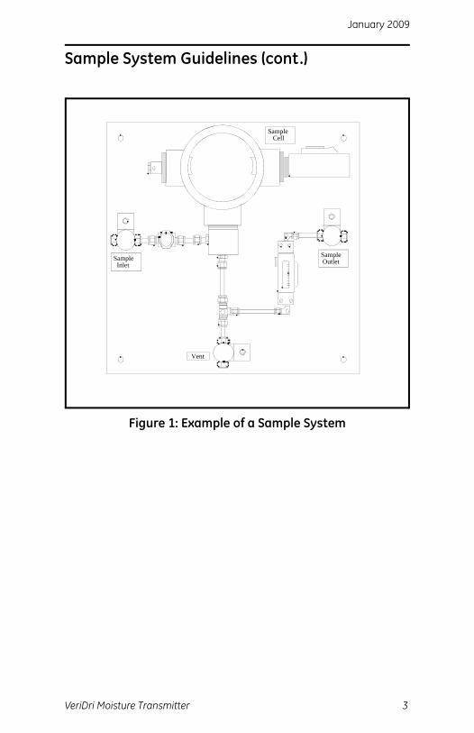
Before constructing a sample system, you should consult a GE Applications Engineer and adhere to the guidelines below. See Figure 1 on the next page for an example of a sample system.
• Consult Specifications on page 13 for dimensions and other requirements.
• Sample systems should be kept very simple.
• The transmitter should be installed so it is perpendicular to the sample inlet.
• The sample system should contain as few components as possible and all or most of those components should be located downstream of the measurement location.
• If possible, you should use stainless steel material for all wetted parts.
• Sample system components should not be made of any material that will affect measurement. Most common filters and pressure regulators are not suitable for sample systems because they have wetted parts that may absorb or release components (such as moisture) into the sample system. They may also allow ambient contamination to enter the sample system.
2 VeriDri Moisture Transmitter
January 2009
Sample System Guidelines (cont.)
Figure 1: Example of a Sample System
Sample Cell
Sample Inlet
Sample Outlet
Vent
VeriDri Moisture Transmitter 3

January 2009
Inserting the Transmitter in the Sample System/Process
!CAUTION!If you are mounting the VeriDri directly into
the process line, you must consult the factoryfor proper installation instructions and precautions
before beginning the following procedure.
Use the steps below to install the VeriDri:
1. Make sure the sintered or sheet stainless-steel shield is in place. The shield protects the aluminum oxide sensor from damaging elements in the process.
2. The probe is mounted into the process via the 3/4-16 straight male thread located on the probe. Thread the probe end of the transmitter into the process/sample system fitting. Make sure not to cross thread it.
Shield
3/4-16 UNF-2A
4 VeriDri Moisture Transmitter

January 2009
Inserting the Transmitter in the Sample System/Process (cont.)3. Using a 1-1/8 in. wrench, tighten the probe securely into the
process using the probe hex nut.
!CAUTION!Do not apply force to the transmitter
module to tighten the unit into its fitting.
Probe Hex Nut
VeriDri Moisture Transmitter 5
January 2009
Making Wiring Connections
You must wire the transmitter using the factory-supplied cable which is available in a variety of lengths.
Note: If you need to lengthen cables, refer to Table 1 below to splice an extension onto the existing cable. Connect positive to positive and negative to negative.
Use the following steps to wire the transmitter to your system.
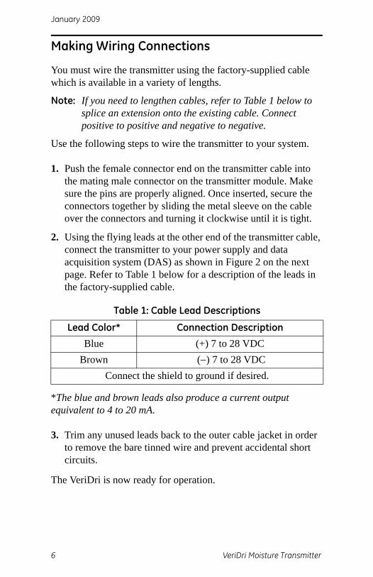
1. Push the female connector end on the transmitter cable into the mating male connector on the transmitter module. Make sure the pins are properly aligned. Once inserted, secure the connectors together by sliding the metal sleeve on the cable over the connectors and turning it clockwise until it is tight.
2. Using the flying leads at the other end of the transmitter cable, connect the transmitter to your power supply and data acquisition system (DAS) as shown in Figure 2 on the next page. Refer to Table 1 below for a description of the leads in the factory-supplied cable.
*The blue and brown leads also produce a current output equivalent to 4 to 20 mA.
3. Trim any unused leads back to the outer cable jacket in order to remove the bare tinned wire and prevent accidental short circuits.
The VeriDri is now ready for operation.
Table 1: Cable Lead Descriptions
Lead Color* Connection DescriptionBlue (+) 7 to 28 VDC
Brown (−) 7 to 28 VDCConnect the shield to ground if desired.
6 VeriDri Moisture Transmitter

January 2009
Making Wiring Connections (cont.)
Figure 2: Wiring Connections
Pow
er a
ndM
easu
rem
ent
Circ
uits
+ 7-28
VD
C
7-28
VD
C−
Blue
Brow
n
Not
e: T
he b
lue
and
brow
n le
ads
also
gen
erat
e a
curr
ent o
utpu
t equ
ival
ent t
o 4
to 2
0 m
A.
VeriDri Moisture Transmitter 7

January 2009
Operating the Transmitter
After proper installation, the VeriDri Transmitter is very easy to use; simply power the unit up and you are ready to begin taking measurements. Since the VeriDri stores moisture calibration data in non-volatile FLASH memory, you do not have to enter data manually or worry about losing data during a power loss.
Probes may need to be cleaned occasionally depending on the application. Consult a GE Applications Engineer for required cleaning intervals.
If a problem should arise with the probe, see Error Handling below for how the transmitter reacts to error conditions.
!CAUTION!Any attempt to open the module or remove
the sensor probe will void the warranty.
Powering Up
After the VeriDri is wired as described in the previous section, you may apply power to the unit. The transmitter takes approximately 20 seconds to initialize and begin normal operation. The unit will meet specified accuracy in 3 minutes.
Error Handling
In the event of an error condition, the analog output reading is forced to the following values:
• ≥ 22 mA to indicate a shorted probe
• ≤ 3.5 mA to indicate an open probe
8 VeriDri Moisture Transmitter
January 2009
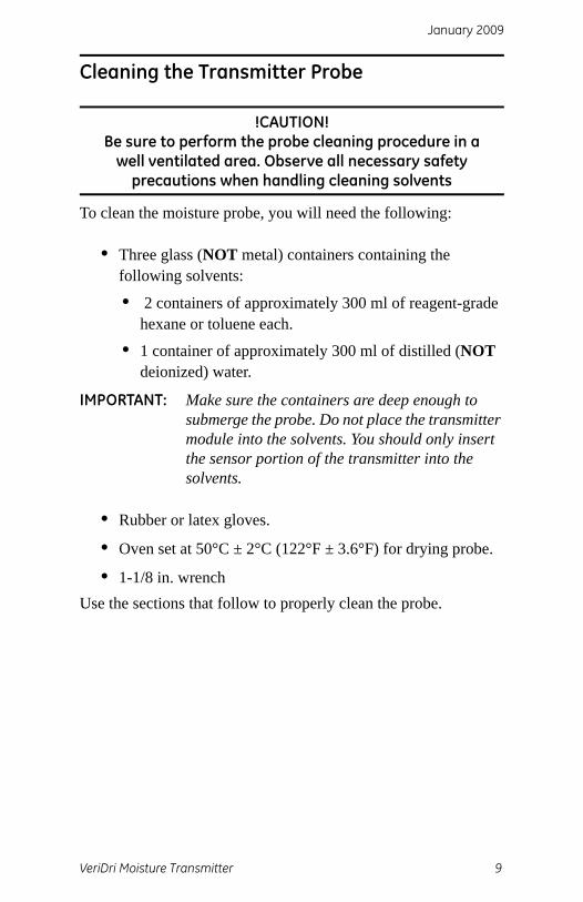
Cleaning the Transmitter Probe
!CAUTION!Be sure to perform the probe cleaning procedure in a
well ventilated area. Observe all necessary safety precautions when handling cleaning solvents
To clean the moisture probe, you will need the following:
• Three glass (NOT metal) containers containing the following solvents:
• 2 containers of approximately 300 ml of reagent-grade hexane or toluene each.
• 1 container of approximately 300 ml of distilled (NOT deionized) water.
IMPORTANT: Make sure the containers are deep enough to submerge the probe. Do not place the transmitter module into the solvents. You should only insert the sensor portion of the transmitter into the solvents.
• Rubber or latex gloves.
• Oven set at 50°C ± 2°C (122°F ± 3.6°F) for drying probe.
• 1-1/8 in. wrenchUse the sections that follow to properly clean the probe.
VeriDri Moisture Transmitter 9

January 2009
Removing the Transmitter
Use the following steps to remove the transmitter from the installation site:
Note: Once the probe is cleaned, it must dry in the oven for 24 hours.
1. Using a 1-1/8 in. wrench, unthread the transmitter from the fitting on the sample system/process using the probe hex nut as shown below.
2. Record the dew point of the ambient air.
3. Disconnect the cable from the module.
4. Unscrew the stainless-steel shield from the probe mount and carefully remove it without touching the sensor.
!CAUTION!Any attempt to open the module or remove
the probe from the module will void the warranty.
Probe Hex Nut
Shield
10 VeriDri Moisture Transmitter

January 2009
Soaking the Sensor and Shield
!CAUTION!Do not place the transmitter module into the solvents.
You should only insert the sensor portion of the transmitter into the solvents. Also, do not allow the sensor to come into contact with the surfaces of the
cleaning containers or any other hard surface.
1. Wearing gloves, place the sensor in the first container of hexane or toluene and allow it to soak for 10 minutes.
2. Remove the sensor from the hexane or toluene and soak it in the container of distilled water for 10 minutes.
3. Remove the sensor from the distilled water and soak it in the second (clean) container of hexane or toluene for 10 minutes.
4. Remove the sensor from the hexane or toluene and set it aside until the shield has completed the cleaning cycle.
5. Repeat steps 1 to 3, above, to clean the shield. To ensure the removal of any contaminants that may have become embedded in the porous walls of the shield, swirl the shield in the solvents during the soaking procedure.
6. Remove the shield from the hexane or toluene.
7. Carefully replace the shield over the exposed sensor without touching it.
8. Place the sensor with the shield in an oven set at 50°C ± 2°C (122°F ± 3.6°F) for 24 hours.
VeriDri Moisture Transmitter 11

January 2009
Evaluating the Probe1. Re-connect the cable to the transmitter module and measure
the dew point. Make sure you measure the same ambient air as measured in step 2 on page 10.
2. Compare the two ambient air readings. If the new ambient air reading is within ±2°C (±3.6°F) of the first reading, the cleaned probe is properly calibrated and may be reinstalled. If it is not, proceed to step 3 below.
3. If the probe is still not reading the ambient air accurately, repeat the cleaning procedure using soaking times that are 5 times the previous cleaning sequence, until two consecutive ambient air readings are identical.
If the above cleaning procedure does not result in accurate readings, contact the factory for assistance.
12 VeriDri Moisture Transmitter

January 2009
Specifications
Moisture Ranges
• –110o to 20°C
• –110o to –50°C
• –90°C to 10°C
• –80°C to –30°C
• –80° to 20°C
• –30o to 20°C
• –130o to 70°F
• –130o to –40°F
• –40o to 70°F
• –50o to 50°F
• -100° to 0°F
• 0 to 10 PPMv
• 0 to 100 PPMv
• 0 to 1000 PPMv
• 0 to 10,000 PPMv
Note: PPMv ranges based on constant pressure, provided at time of order placement.
Operating Temperature
–40° to 60°C (–40° to 140°F)
Storage Temperature
70°C (158oF) maximum. The probe should be stored with the plastic cover and desiccant packet threaded onto the probe. Store in a cool, dry environment.
VeriDri Moisture Transmitter 13
January 2009
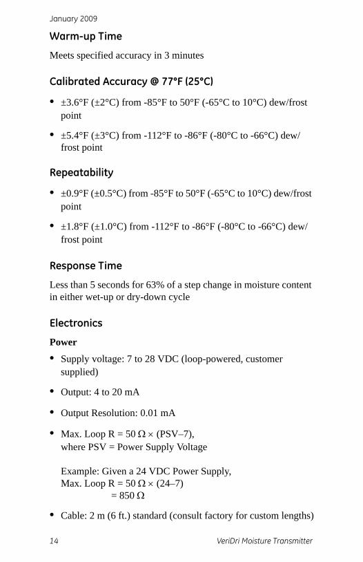
Warm-up Time
Meets specified accuracy in 3 minutes
Calibrated Accuracy @ 77°F (25°C)
• ±3.6°F (±2°C) from -85°F to 50°F (-65°C to 10°C) dew/frost point
• ±5.4°F (±3°C) from -112°F to -86°F (-80°C to -66°C) dew/frost point
Repeatability
• ±0.9°F (±0.5°C) from -85°F to 50°F (-65°C to 10°C) dew/frost point
• ±1.8°F (±1.0°C) from -112°F to -86°F (-80°C to -66°C) dew/frost point
Response Time
Less than 5 seconds for 63% of a step change in moisture content in either wet-up or dry-down cycle
Electronics
Power
• Supply voltage: 7 to 28 VDC (loop-powered, customer supplied)
• Output: 4 to 20 mA
• Output Resolution: 0.01 mA
• Max. Loop R = 50 Ω × (PSV–7),where PSV = Power Supply Voltage
Example: Given a 24 VDC Power Supply,Max. Loop R = 50 Ω × (24–7) = 850 Ω
• Cable: 2 m (6 ft.) standard (consult factory for custom lengths)
14 VeriDri Moisture Transmitter

January 2009
Mechanical
Sample Connection
• 3/4 in. (16 mm) 16 straight male thread with O-ring
• G 1/2 in with optional adapter
Operating Pressure5 µHg to 5,000 psig (345 bar)
EnclosureType 4X/IP67
European ComplianceComplies with the following:
• EMC Directive 2004/108/EC and PED 97/23/EC for DN<25
• EN 61326:1998Class A, Annex A, Continuous Unmonitored Operation (For EN 61000-4-3 transmitter meets performance criteria A and in a number of frequencies, criteria B per EN 61326)
Dimensions
• Overall: 6.76 × 1.13 in. (17.17 × 2.87 cm)
• Electronics with cable: 4.08 × 1.13 in. diameter(10.36 × 2.87 cm)
• Weight: 5 oz (140 grams)
VeriDri Moisture Transmitter 15

January 2009
Moisture Sensor
Sensor TypeThin-film aluminum oxide moisture sensor probe
CalibrationEach sensor is individually computer-calibrated against known moisture concentrations, traceable to NIST
Calibration IntervalSensor recalibration at GE Sensing is recommended every six to 12 months depending on application
Calibration DataFactory-calibrated, stored in FLASH
Flow Rate
• Gases: Static to 10,000-cm/s linear velocity at a pressure of 1 atm.
• Liquids: Static to 10-cm/s linear velocity at density of1 g/cc
16 VeriDri Moisture Transmitter
January 2009
Warranty
Each instrument manufactured by GE Sensing, Inc. is warranted to be free from defects in material and workmanship. Liability under this warranty is limited to restoring the instrument to normal operation or replacing the instrument, at the sole discretion of GE Sensing, Inc. Fuses and batteries are specifically excluded from any liability. This warranty is effective from the date of delivery to the original purchaser. If GE Sensing, Inc. determines that the equipment was defective, the warranty period is:
• one year from delivery for electronic or mechanical failures
• one year from delivery for sensor shelf life
If GE Sensing, Inc. determines that the equipment was damaged by misuse, improper installation, the use of unauthorized replacement parts, or operating conditions outside the guidelines specified by GE Sensing, Inc., the repairs are not covered under this warranty.
The warranties set forth herein are exclusive and are in lieu of all other warranties whether statutory, express or
implied (including warranties or merchantability and fitness for a particular purpose, and warranties arising from course
of dealing or usage or trade).
January 2009
Return Policy
If a GE Sensing, Inc. instrument malfunctions within the warranty period, the following procedure must be completed:
1. Notify GE Sensing, Inc., giving full details of the problem, and provide the model number and serial number of the instrument. If the nature of the problem indicates the need for factory service, GE Sensing, Inc. will issue a RETURN AUTHORIZATION NUMBER (RAN), and shipping instructions for the return of the instrument to a service center will be provided.
2. If GE Sensing, Inc. instructs you to send your instrument to a service center, it must be shipped prepaid to the authorized repair station indicated in the shipping instructions.
3. Upon receipt, GE Sensing, Inc. will evaluate the instrument to determine the cause of the malfunction.
Then, one of the following courses of action will then be taken:
• If the damage is covered under the terms of the warranty, the instrument will be repaired at no cost to the owner and returned.
• If GE Sensing, Inc. determines that the damage is not covered under the terms of the warranty, or if the warranty has expired, an estimate for the cost of the repairs at standard rates will be provided. Upon receipt of the owner’s approval to proceed, the instrument will be repaired and returned.
GESensing DECLARATION
OFCONFORMITY
We, GE Sensing 1100 Technology Park Drive
Billerica, MA 01821USA
declare under our sole responsibility that the
VeriDri™ Moisture Transmitter
to which this declaration relates, is in conformity with the following standards:
• EN 61326:1998, Class A, Annex A, Continuous Unmonitored Operation(For EN 61000-4-3, the above units meet performance Criteria A, and in a limitednumber of frequencies, performance Criteria B per EN 61326.)
• EN 60529:1991+A1:2000IP67
following the provisions of the 2004/108/EC EMC Directive.
The units listed above and any ancillary sample handling systems supplied with them do not bear CE marking for the Pressure Equipment Directive, as they are supplied in accordance with Article 3, Section 3 (sound engineering practices and codes of good workmanship) of the Pressure Equipment Directive 97/23/EC for DN<25.
January 8, 2009Date of Issue Mr. Gary Kozinski
Certification & Standards, Lead Engineer
CERT-DOC-H1 (August 2004)

GESensing DECLARATION
DECONFORMITE
Nous, GE Sensing 1100 Technology Park Drive
Billerica, MA 01821USA
déclarons comme étant de notre seule responsabilité que le
Transmetteur d’humidité VeriDri™
sur lequel porte ce document, est conforme aux spécifications suivantes :
• EN 61326:1998, Classe A, Annexe A, Fonctionnement continu sans surveillance(Pour EN 61000-4-3, les appareils ci-dessus sont conformes au critère A de performance et, dans un nombre limité de fréquences, au critère B de performance, selon EN 61326.)
• EN 60529:1991+A1:2000IP67
conformément aux dispositions de la directive 2004/108/EC (compatibilité électromagnétique).
Les appareils indiqués plus haut et tous les accessoires d’échantillonnage fournis avec ne portent pas la marque CE pour la directive concernant les équipements de pression, dans la mesure où ils sont fournis conformément à l’article 3, section 3 (pratiques d’ingénierie sûres et codes de bienfacture) de la directive concernant les équipements de pression 97/23/EC pour DN<25.
8 janvier 2009Date d’émission Mr. Gary Kozinski
Certification et normes, ingénieur de fil
CERT-DOC-H1 (August 2004)

GESensing KONFORMITÄTS-
ERKLÄRUNG
Wir, GE Sensing 1100 Technology Park Drive
Billerica, MA 01821USA
erklären unter alleiniger Eigenverantwortlichkeit, dass die Produkte
VeriDri™ Feuchtigkeitsmesswandler
auf das sich diese Deklaration bezieht, die folgenden Normen erfüllen:
• EN 61326:1998, Class A, Annex A, kontinuierlicher, überwachungsfreier Betrieb(Für EN 61000-4-3 erfüllen die obigen Geräte die Leistungskriterien A und in bei einer begrenzten Anzahl von Frequenzen die Leistungskriterien B gemäß EN 61326.)
• EN 60529:1991+A1:2000IP67
und dass sie die Anforderungen der EMC-Direktive 2004/108/EC einhalten.
Die oben aufgeführten Geräte und zugehörige, mitgelieferte Schallwandler (Messrohre werden in einer separaten Konformitätserklärung behandelt) tragen keineCE-Kennzeichnung gemäß der Druckgeräte-Richtlinie, da sie in Übereinstimmung mit Artikel 3, Absatz 3 (gute Ingenieurpraxis) der Druckgeräte-Richtlinie 97/23/EG für DN<25 geliefert werden.
8. Januar 2009Außtellungsdatum Hr. Gary Kozinski
Bescheinigung und Normen, Leitungsingenieur
CERT-DOC-H1 (August 2004)

USA1100 Technology Park DriveBillerica, MA 01821-4111Web: www.gesensinginspection.com
IrelandShannon Industrial EstateShannon, County ClareIreland


