
Technical Guide
FEATURE OVERVIEW AND CONFIGURATION GUIDE
VRF-lite
IntroductionIn IP-based networks, VRF stands forVirtual Routing and Forwarding. This technology allowsmultiple routing domains to co-exist within the same device at the same time. As the routingdomains are independent, overlapping IP addresses can be used without causing conflict. Inlarge service provider networks, virtual routing and forwarding is used in conjunction withMPLS - Multi Protocol Label Switching - to separate each customer’s traffic into its own wideareaVPN.VRF is also known asVPN Routing and Forwarding (when used with MPLS), and isalso known as Multi-VRF.
What is VRF-lite?
VRF-lite is VRF without the need to run MPLS in the network. VRF-lite is used for isolating
customer networks - it allows multiple secure customer routing domains to co-exist in one
physical device simultaneously, which remain completely isolated from each other.
VRF-lite also allows the re-use of IP addresses on the same physical device. An IP addressrange in oneVLAN used in oneVRF domain can simultaneously be used in anotherVLAN ina differentVRF domain within the same device. WhileVRF-lite will segregate traffic fromdifferent customers/clients, VRF-lite can also allow for route leakage betweenVRF domains(inter-VRF communication), by using static inter-VRF routes and/or dynamic route leakage viaBGP and associated route maps. This provides filtered access from oneVRF routing domainto another where the IP address ranges do not overlap.
This guide describesVRF-lite’s key features and the generic commands used to configureVRF-lite. There are a number of simple configuration examplesprovided to illustrate its use with OSPF, RIP, and BGP routing protocols.
alliedtelesis.com xC613-22046-00 REV B

Introduction
This is followed with a configuration breakdown of a complex inter-VRF scenario, whichincludes overlapping IP addresses and a range of routing protocols. Dynamic inter-VRFcommunication between the global VRF domain and aVRF instance is also explained. Finally,a short list of diagnostics commands are provided to help troubleshootVRF-related issues.
Which products and software version does it apply to?
The information provided in this document applies to:
SwitchBlade x908™ and x900 series switches running 5.4.1and above.
x930 switches running AlliedWare Plus™ version 5.4.2 and above.
AT-DC2552XS/L3 switch running 5.4.1and above
x610 switches running AlliedWare Plus™ version 5.4.2 and above.
SBx8100 series switches with CFC-960 controller running AlliedWare Plus 5.4.4 and
above.
Software feature licenses
The VRF-lite feature requires a special software license. Without a proper license installed,
configuring VRFs is not possible. A VRF-lite feature license key is distributed in the Advanced
Layer 3 License Bundle that allows up to 8 VRF-lite instances to be configured.
The number of configurableVRF-lite instances can be increased via an additionalVRF-lite-63 license.
The Advanced Layer 3 License Bundle containing theVRF-lite feature and the additionalVRF-lite-63 license are available through the AlliedWare Plus licensing web portal: (http://licensing.alliedtelesis.com/).
AVRF-lite-63 license requires an Advanced Layer 3 License Bundle to work.
Note: Enabling multiple VRFs means there will be more routing entries on the device system-
wide. This may affect the number of routes used by BGP or OSPF specified by the
licence key on the device.
Command summary
All the existing CLI commands available in the current non-VRF environment are availablewith no change.
Page 2 | VRF-lite

Introduction
ContentIntroduction ............................................................................................................................................................................ 1
What isVRF-lite? ......................................................................................................................................................... 1
Which products and software version does it apply to?..................................................................... 2
Software feature licenses ....................................................................................................................................... 2
Command summary................................................................................................................................................. 2
Glossary .................................................................................................................................................................................... 5
UnderstandingVRF-lite ..................................................................................................................................................... 6
VRF-lite security domains ...................................................................................................................................... 7
Route table and interface management withVRF-lite ........................................................................... 7
Inter-VRF communication ...................................................................................................................................... 9
Static and dynamic inter-VRF routing............................................................................................................10
VRF-lite features in AlliedWare Plus..............................................................................................................11
Route limiting perVRF instance........................................................................................................................12
VRF-aware utilities within AlliedWare Plus................................................................................................12
ConfiguringVRF-lite ..........................................................................................................................................................14
Static inter-VRF routing .........................................................................................................................................18
Dynamic inter-VRF Communication Explained ................................................................................................19
The Forwarding Information Base (FIB) and routing protocols.....................................................19
Inter-VRF communication via BGP .................................................................................................................21
HowVRF-lite security is maintained ..............................................................................................................25
SimpleVRF-lite Configuration Examples ..............................................................................................................26
MultipleVRFs without inter-VRF communication ..................................................................................26
Dynamic inter-VRF communication with RIP routing to external peers ..................................29
Dynamic inter-VRF communication with BGP routing to external peers ...............................30
Dynamic inter-VRF communication with OSPF routing to external peers.............................31
Inter-VRF Configuration Examples with Internet Access ............................................................................34
Configuring a Complex Inter-VRF Solution ........................................................................................................45
Network description..............................................................................................................................................45
Configuration breakdown....................................................................................................................................47
VCStack andVRF-lite .......................................................................................................................................................72
SharingVRF routing and double tagging on the same port .............................................................76
Configuring DNS Relay and DHCP Relay to beVRF Aware....................................................................79
Introduction .................................................................................................................................................................79
DNS operation withVRF-lite.............................................................................................................................79
Configuring DNS operation withVRF-lite..................................................................................................80
DHCP operation withVRF-lite.........................................................................................................................81
Combined DNS Relay DHCP Relay solution..........................................................................................82
Device configuration...............................................................................................................................................83
Dynamic Inter-VRF Routing Between the Global VRF Domain and aVRF Instance ...................87
BGP configuration tips...........................................................................................................................................88
VRF-lite | Page 3
Introduction
Dynamic inter-VRF communication with i-BGP routing to external peer .............................. 90
Dynamic inter-VRF communication with e-BGP routing to external peer............................. 91
Route Limits ......................................................................................................................................................................... 93
Configuring static route limits ........................................................................................................................... 93
Configuring dynamic route limits .................................................................................................................... 94
Utilities Available withinVRF-lite............................................................................................................................... 96
Utilities Unavailable withinVRF-lite ......................................................................................................................... 97
VRF-lite Usage Guidelines ............................................................................................................................................ 98
Useful VRF-Related Diagnostics Command List .............................................................................................. 99
Page 4 | VRF-lite
Glossary
Glossary
ACRONYM DESCRIPTION
AS Autonomous System
ACL Access Control List
BGP Border Gateway Protocol
FIB Forwarding Information Base
MPLS Multi-Protocol Label Switching
OSPF Open Shortest Path First
RIP Routing Information Protocol
VPN Virtual Private Network
VR Virtual Router
VRF Virtual Routing and Forwarding
VRF-lite VRF without MPLS network
CE Customer edge
PE Provider edge
RD Route Distinguisher
RT RouteTarget
VCStack Virtual Chassis Stacking
VRF-lite | Page 5

Understanding VRF-lite
Understanding VRF-lite
VPN 1Customer A
VPN 2Customer B
VPN 1Customer A
VPN 2Customer B
MPLSnetwork
CE = Customer edge device
PE = Provider edge router
MPLS-VRFdevice
MPLS-VRFdevice
CE PE CEPE
The purpose ofVRF is to enable separate IP networks, possibly using overlapping IPaddresses, to share the same links and routers. IP traffic is constrained to a set of separate IPVirtual Private Networks (VPNs). TheseVPNs provide a secure way for a service providerto carry multiple customers’ IP networks across a common infrastructure. The differentcustomers’ IP networks are able to operate in complete isolation from each other, so there isno requirement for them to use separate IP address ranges, and there is no leakage of trafficfrom oneVPN to another, unless specifically requested.
A fullVRF solution commonly involves different portions of the IP networks being connectedto each other by an MPLS backbone network. The separate IP networks will be allocateddifferent tags in the MPLS network. So the full VRF solution involves not only managingmultiple separate IP networks within the same routers, but also a network-to-MPLS tagmapping process.
In the full VRF solution a distinction is made between Customer Edge (CE) routers andProvider Edge (PE) routers. CE routers aggregate the separate IP networks of the serviceprovider’s different clients. PE routers connect the IP networks to the MPLS backbone.
VRF-lite is a subset of the full VRF solution. In aVRF-lite solution there are multiple IPnetworks sharing the same routers, but no MPLS core is involved. So, VRF-lite is just thecustomer edge router part ofVRF, without the provider edge router part.
VRF-lite facilitates multiple separate routing tables within a single router - one routing tableassociated with each of the customerVPNs connected to the device. MultipleVRF instancesare defined within a router. One or more Layer 3 interfaces (VLAN) are associated with eachVRF instance forming an isolatedVRF routing domain. A Layer 3 interface cannot belong tomore than oneVRF instance at any time.
Page 6 | VRF-lite

Understanding VRF-lite
PC1
PC2
SW
PC5
PC6
vlan1 1.1.1.1/24
PC3
PC4
Company A
VRF green
VRF blue
VRF red
vlan2 10.1.1.1/8
vlan6 10.1.1.1/24
vlan5 1.1.1.1/24
vlan3 1.1.1.1/24
vlan4 10.1.1.1/16
Company B
Company C
VRF-lite security domains
VRF-lite provides network isolation on a single device at Layer 3. EachVRF domain can usethe same or overlapping network addresses, as they have independent routing tables. Thisseparation of the routing tables prevents communication to Layer 3 interfaces in otherVRFdomains on the same device. Each Layer 3 interface belongs to exactly oneVRF instance andtraffic between two Layer 3 interfaces on the sameVRF instance is allowed as normal. But bydefault, interfaces in otherVRF instances are not reachable as no route exits between theinterfaces unless explicitly configured via Inter-VRF routing.
For example, on a device threeVRF instances (VRF red, VRF green, andVRF blue) areconfigured for three different companies. Devices PC1 and PC2 from Company A cancommunicate normally within the confines ofVRF red, but none of PC1’s and PC2’s trafficcan be seen by other devices inVRF green andVRF blue.
Route table and interface management with VRF-lite
A key feature that VRF-lite introduces to a router is the existence of multiple IP route tables
within the one router.
By default, before anyVRF is configured, a router will have one route table, and routes via allIP interfaces of the router will be stored in this one table. AsVRF instances are configured onthe router, the original route table remains. This default route table, and its associated IPinterfaces, are then referred to as the default global VRF domain.
Interface management with VRF
Each network interface can belong to only oneVRF. As mentioned above, initially everyinterface is in the default globalVRF domain. As Layer 3 interfaces are moved to the createdVRF instances, they are removed from the global VRF domain, so the global VRF domainmanages a decreasing set of Layer 3 interfaces.
VRF-lite | Page 7

Understanding VRF-lite
awplus(config)#arp ?A.B.C.D IP address of the ARP entrylog Arp logvrf VRF instance
awplus(config)#arp vrf <name> ?A.B.C.D IP address of the ARP entry
When a Layer 3 interface is moved to aVRF instance from the default globalVRF domain, orwhen a Layer 3 interface is moved from oneVRF instance to another via command, theinterface name and id (ifindex) are never changed as a result of the interface movement.However IP configuration on the interface in the previousVRF is unset (removed) beforemoving the interface to a newVRF.
ARP entries associated with the Layer 3 interface are cleared when the interface is movedfrom oneVRF instance to another. In addition (static and dynamic) ARP entries areVRFaware, as the same IP address can be used in other VRF instances.
Adding a VRF-aware static ARP
Route management with VRF
Each VRF instance maintains its own IPv4 routing table independent from the routing table
of the global VRF domain or other VRFs.
Routing entries can be added statically by user command or dynamically by a routing
protocol module such as BGP, OSPF, or RIP within the VRF instance. Use of a dynamic
routing protocol allows for each VRF network to maintain a consistent routing table across
all the devices within the VRF network.
The way that each routing is able to define a separate instance of itself on multiple VRF
instances varies from protocol to protocol:
For BGP, one BGP routing instance will be running for an Autonomous System in the
global VRF domain and individual BGP routing tables will be managed per VRF by using
the address-family feature. One address-family is created for each VRF instance.
For OSPF, one OSPF routing instance is configurable per VRF, and one OSPF instance
is configurable within the global VRF domain.
For RIP, one RIP routing instance will be running in the default global VRF domain and
individual RIP routing tables will be managed per VRF by using the address-family
feature. One address-family is created for each VRF instance.
Note: The command show ip route displays the routes associated with each VRF instance.
Page 8 | VRF-lite
Understanding VRF-lite
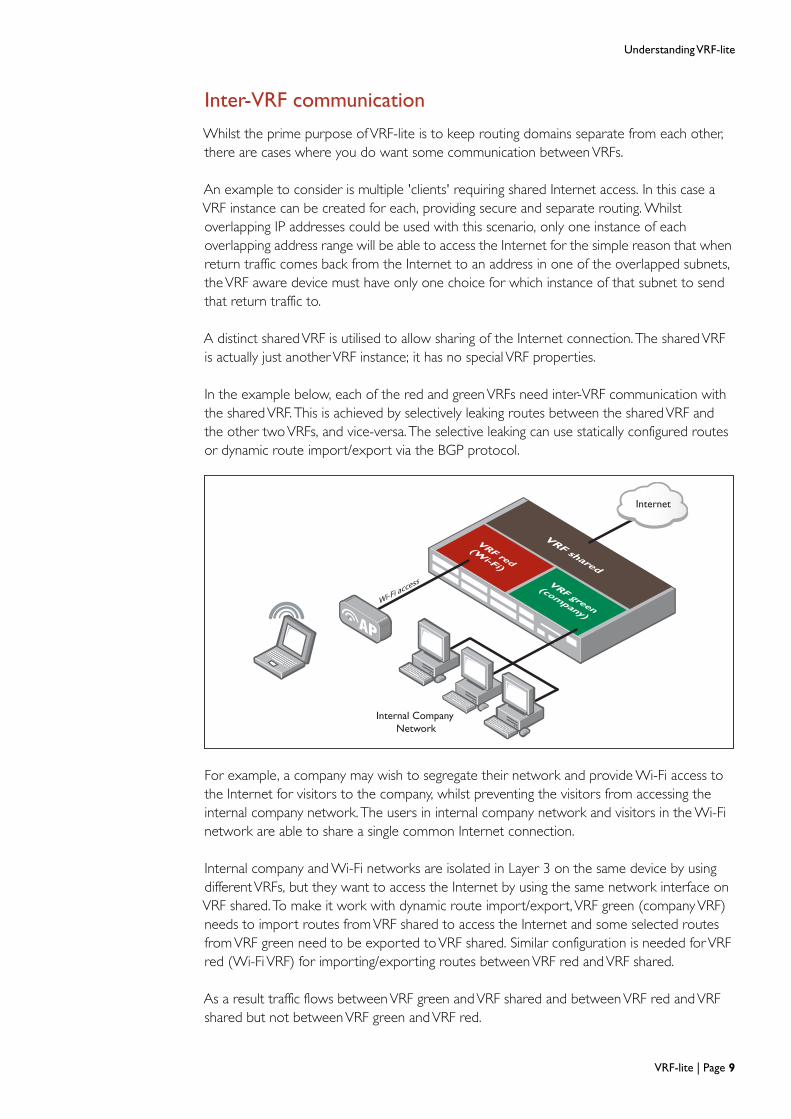
Inter-VRF communication
Whilst the prime purpose of VRF-lite is to keep routing domains separate from each other,
there are cases where you do want some communication between VRFs.
Internal Company
Network
VRF red
(Wi-Fi)
VRF green
(company)
VRF shared
Internet
Wi-Fi access
An example to consider is multiple 'clients' requiring shared Internet access. In this case aVRF instance can be created for each, providing secure and separate routing. Whilstoverlapping IP addresses could be used with this scenario, only one instance of eachoverlapping address range will be able to access the Internet for the simple reason that whenreturn traffic comes back from the Internet to an address in one of the overlapped subnets,theVRF aware device must have only one choice for which instance of that subnet to sendthat return traffic to.
A distinct sharedVRF is utilised to allow sharing of the Internet connection. The sharedVRFis actually just anotherVRF instance; it has no special VRF properties.
In the example below, each of the red and greenVRFs need inter-VRF communication withthe sharedVRF. This is achieved by selectively leaking routes between the sharedVRF andthe other twoVRFs, and vice-versa. The selective leaking can use statically configured routesor dynamic route import/export via the BGP protocol.
For example, a company may wish to segregate their network and provide Wi-Fi access tothe Internet for visitors to the company, whilst preventing the visitors from accessing theinternal company network. The users in internal company network and visitors in the Wi-Finetwork are able to share a single common Internet connection.
Internal company and Wi-Fi networks are isolated in Layer 3 on the same device by usingdifferentVRFs, but they want to access the Internet by using the same network interface onVRF shared. To make it work with dynamic route import/export, VRF green (companyVRF)needs to import routes fromVRF shared to access the Internet and some selected routesfromVRF green need to be exported toVRF shared. Similar configuration is needed forVRFred (Wi-Fi VRF) for importing/exporting routes betweenVRF red andVRF shared.
As a result traffic flows betweenVRF green andVRF shared and betweenVRF red andVRFshared but not betweenVRF green andVRF red.
VRF-lite | Page 9

Understanding VRF-lite
Static and dynamic inter-VRF routing
As mentioned above, "Inter-VRF communication" on page 9, in some circumstances it isrequired to (selectively) allow traffic between two interfaces that are not in the sameVRF.This will be useful if there is common network equipment (e.g. Internet connections orshared resources) that multipleVRFs need to share.
Inter-VRF routing is achieved by statically or dynamically taking a route entry and its next-hopinterface from oneVRF, and adding it into the routing table of another. A dynamic inter-VRFroute can be added by using the BGP route import/export feature. A static inter-VRF routecan be added by a user command. For more information on static routing, see "Static inter-VRF routing" on page 18.
Static and dynamic inter-VRF communication can be used simultaneously or separately.Dynamic inter-VRF communication is only achieved via use of the BGP routing protocol.OSPF and RIP cannot be used to achieve inter-VRF communication.
Internally transferring routes betweenVRF instances is quite separate from the sharing ofroutes of a specificVRF routing domain, with external routers that are members of that samedomain. As mentioned above, all dynamic routing protocols can be used to distribute routinginformation to external peer devices. OSPF, RIP, and BGP can all be used to dynamicallydistribute routes to external peers withinVRF routing domains.
When BGP is used for dynamic inter-VRF communication, routes from other routingprotocols (including connected routes, static routes, OSPF or RIP) are redistributed into aVRF instance’s BGP route table (BGP must be configured and associated with theVRFinstance). OtherVRF instances that are configured with BGP can selectively copy theseroutes into their own separate BGP route tables.
Inter-VRF route leakage interoperates with the exchange of route information. Routes learntfrom external peers in oneVRF domain can be leaked to otherVRF instances and routesleaked into aVRF instance can then be advertised to external peers connected to thatinstance.
The details of dynamic inter-VRF routing are described in "Dynamic inter-VRFCommunication Explained" on page 19.
Page 10 | VRF-lite
Understanding VRF-lite
VRF-lite features in AlliedWare Plus
Here is a summary of the features provided by the AlliedWare PlusVRF-lite implementation:
Multiple independent routing table instances may co-exist within the same device. Thesame or overlapping IP addresses can be present in different route table instances withoutconflicting. All routing table instances remain securely isolated from those existing in otherrouting tables.
By default, no communication occurs betweenVRF instances, facilitating multiple securerouting domains within the sameVRF aware device.
However, inter-VRF communication between routing domains is possible by using eitherstatic inter-VRF routes and/or dynamic filtered route leakage via BGP and its associatedroute maps.
A single device configuration file simplifies management by providing the ability to create,manage, and monitor all VRF instances.
Detailed diagnostic and debugging information is available.
Ability to view routing table information perVRF.
All appropriateVRF related information and error messages can be viewed in thesystem wide log.
Separate instances of routing protocols can be mapped toVRF instances so thatdistribution of route information can be performed on a perVRF domain basis. Thisenables route information to be distributed securely within eachVRF routing domain.
For example:
VRF1 = OSPF routing instance1
VRF2 = OSPF routing instance2
All Layer 3 interfaces and associated switch ports remain in the default globalVRF domainuntil associated with a specificVRF instance.
VRF is supported in HW and SW (including Inter-VRF communications).
The default global VRF domain always exists and cannot be removed. Initially duringstartup, everyVLAN belongs to the default global VRF domain. Also, when aVLAN isremoved from aVRF, it is automatically returned to the default global VRF domain. Onlyone default global VRF domain exists in each physical device.
Static and dynamic routes can be leaked from aVRF instance to the global default VRF.
Selected routes within aVRF instance can be dynamically leaked to otherVRF routingdomains. This applies both to routes that have been statically configured, and to routesthat have been learnt into aVRF instance on the device by routing protocol exchangeswith external peer routers.
When aVRF instance has received routes leaked from otherVRF instances, that instancecan advertise those routes to external peer routers connected to interfaces in thatVRFinstance, via the routing protocol operating within theVRF instance.
VRF-lite | Page 11

Understanding VRF-lite
Route limiting per VRF instance
In a multi-VRF network environment, it may be problematic if oneVRF injects too manyroutes and fills up the hardware forwarding table (FIB) on the device, which can affect otherVRFs as well as the global VRF. For more information see "Route Limits" on page 93
VRF-aware utilities within AlliedWare Plus
Some network utility and management features such as ping, traceroute, telnet client, SSHclient, and tcpdump are supported in aVRF aware manner.
VRF aware services include
Ping
awplus#ping ?WORD Ping destination address or hostnameip IP echoipv6 IPv6 echovrf VRF instance (source VRF)<cr>
awplus#ping vrf <name> ?WORD Ping destination address or hostnameip IP echo
awplus#ping vrf <name> x.x.x.x
awplus#ping vrf <name> x.x.x.x ?broadcast Ping to a broadcast addressdf-bit Enable do-not-fragment bit in IP headerinterval Specify interval between pingspattern Specify data patternrepeat Specify repeat countsize Specify datagram sizesource Specify source address or interface nametimeout Specify timeout intervaltos Specify type of service<cr>
Trace route
awplus#traceroute ?WORD Trace route to destination address or hostnameip IP Traceipv6 IPv6 tracevrf VRF instance<cr>
awplus#traceroute vrf <name> ?WORD Trace route to destination address or hostnameip IP Trace
awplus#traceroute vrf <name> x.x.x.x
Page 12 | VRF-lite

Understanding VRF-lite
Telnet client
awplus#telnet ?WORD IPv4/IPv6 address or hostname of a remote systemip IP telnetipv6 IPv6 telnetvrf VRF instance
awplus#telnet vrf <name> ?WORD IPv4 address or hostname of a remote systemip IP telnet
awplus#telnet vrf <name> ip x.x.x.x
SSH client
awplus#ssh ?HOSTNAME IP/IPv6 address or hostname of a remote serverclient Configure global SSH client parametersip IP SSHipv6 IPv6 SSHport SSH server portuser Login userversion SSH client versionvrf VRF instance
awplus#ssh vrf <name> ?HOSTNAME IP/IPv6 address or hostname of a remote serverip IP SSHport SSH server portuser Login userversion SSH client version
awplus#ssh vrf <name> x.x.x.x
TCP dump
awplus#tcpdump ?LINE Execute tcpdumpvrf VRF instance<cr>
awplus#tcpdump vrf <name> ?LINE Execute tcpdump<cr>
awplus#tcpdump vrf <name>
In thisVRF-lite implementation, other Layer 4+ services and applications are not supportedon a per-VRF basis - such asTelnet server, SSH server, file copy, system log, SNMP server,DHCP server, NTP server, etc. However, these services will remain supported in the globalVRF domain context, which is same as in a non-VRF environment.
VRF-lite | Page 13

Configuring VRF-lite
Configuring VRF-lite
The following section describes the generic commands used to configure VRF-lite.
CONFIGURING ACLS PURPOSE
Step 1 Enter Global Configuration mode.
Step 2 Optional. This command configures astandard named access-control-list (ACL).Matching networks (routes) are eitherimported to or exported from aVRFinstance to BGP. Alternatively, matchingnetworks are denied from being importedto or exported from aVRF instance to BGP.This command is optionally used in thecontext ofVRF when using BGP to facilitateinter-VRF communications. These optionalACLs should be configured before anyinter-VRF communication is configured, toprevent unnecessary routes from beingleaked from oneVRF to another.
CONFIGURINGVRFS PURPOSE
Step 1 Create a namedVirtual Router Forwarding(VRF) instance. If the optional LocalInterface (LO) parameter not specified, alocal interface is automatically created andassociated with theVRF instance. If the LOparameter is specified, it allows the user tocontrol which LO is associated with aparticularVRF instance.
Step 2 Optional. Create a route distinguisher (rd)in the form of an ASN, which alsoreferences a specificVRF instance. Format isin the form ASN:VRF instance. Thiscommand is required if using BGP tofacilitate inter-VRF communication.
Step 3 Optional. Exports routes from theVRFinstance to BGP.
Step 4 Optional. Imports routes from BGP intotheVRF instance.
Step 5 Optional. Configure an import map, whichreferences a route map, and associatedACL. Used to selectively import routes intotheVRF instance from BGP.
Step 6 Optional. Configure an export map, whichreferences a route map, and associatedACL. Used to selectively export routesfrom theVRF instance to BGP.
Step 7 Return to Global Configuration mode.
awplus# conf t
awplus(config)# access-list standard<access-list-name> {deny|permit}<network>
awplus(config)#ip vrf <vrf-name> <lo-interface-number>
awplus(config-vrf)#rd <routedistinguisher>
awplus(config-vrf)#route-target export<ASN>
awplus(config-vrf)#route-target import<ASN>
awplus(config-vrf)#import map <route-map-name>
awplus(config-vrf)#export map <route-map-name>
awplus(config-vrf)#exit
Page 14 | VRF-lite
Configuring VRF-lite
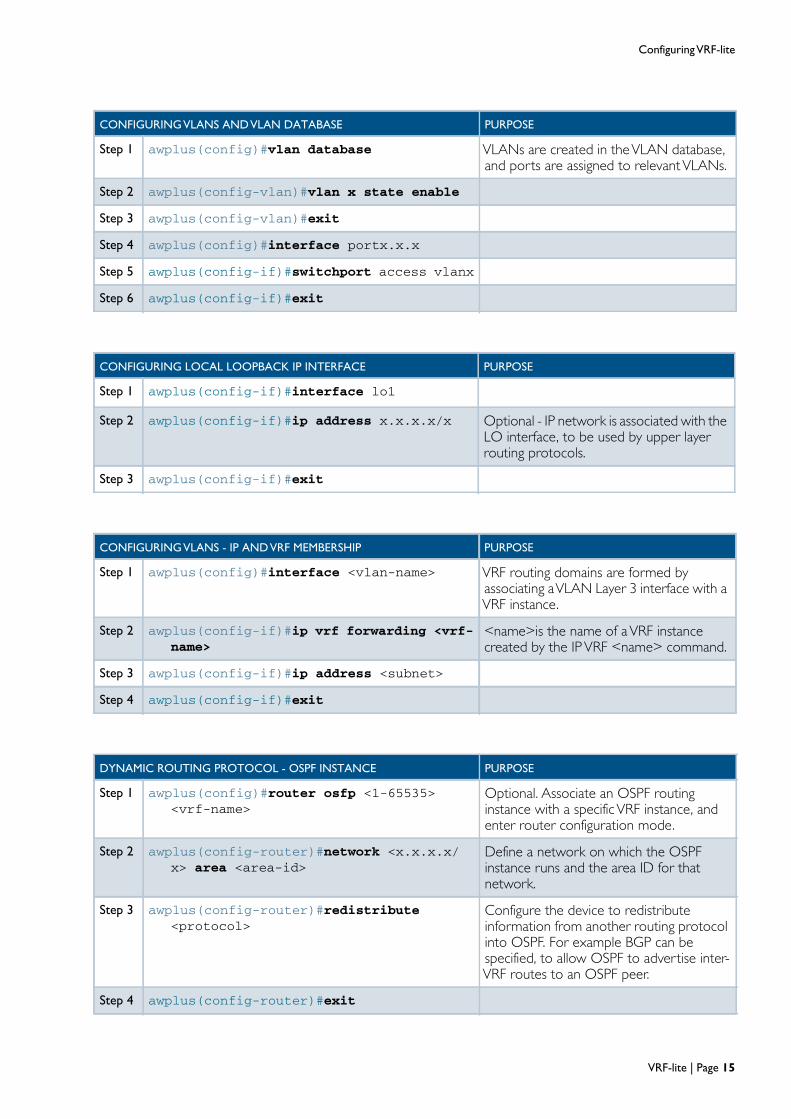
CONFIGURINGVLANS ANDVLAN DATABASE PURPOSE
Step 1 awplus(config)#vlan database VLANs are created in theVLAN database,and ports are assigned to relevantVLANs.
Step 2 awplus(config-vlan)#vlan x state enable
Step 3 awplus(config-vlan)#exit
Step 4 awplus(config)#interface portx.x.x
Step 5 awplus(config-if)#switchport access vlanx
Step 6 awplus(config-if)#exit
CONFIGURING LOCAL LOOPBACK IP INTERFACE PURPOSE
Step 1 awplus(config-if)#interface lo1
Step 2 awplus(config-if)#ip address x.x.x.x/x Optional - IP network is associated with theLO interface, to be used by upper layerrouting protocols.
Step 3 awplus(config-if)#exit
CONFIGURINGVLANS - IP ANDVRF MEMBERSHIP PURPOSE
Step 1 awplus(config)#interface <vlan-name> VRF routing domains are formed byassociating aVLAN Layer 3 interface with aVRF instance.
Step 2 awplus(config-if)#ip vrf forwarding <vrf-name>
<name>is the name of aVRF instancecreated by the IPVRF <name> command.
Step 3 awplus(config-if)#ip address <subnet>
Step 4 awplus(config-if)#exit
DYNAMIC ROUTING PROTOCOL - OSPF INSTANCE PURPOSE
Step 1 awplus(config)#router osfp <1-65535><vrf-name>
Optional. Associate an OSPF routinginstance with a specificVRF instance, andenter router configuration mode.
Step 2 awplus(config-router)#network <x.x.x.x/x> area <area-id>
Define a network on which the OSPFinstance runs and the area ID for thatnetwork.
Step 3 awplus(config-router)#redistribute<protocol>
Configure the device to redistributeinformation from another routing protocolinto OSPF. For example BGP can bespecified, to allow OSPF to advertise inter-VRF routes to an OSPF peer.
Step 4 awplus(config-router)#exit
VRF-lite | Page 15

Configuring VRF-lite
DYNAMIC ROUTING PROTOCOL - RIP ADDRESS-FAMILY PURPOSE
Step 1 awplus(config)#router rip Optional. Enter router configuration modefor RIP.
Step 2 awplus(config-router)#address-familyipv4 vrf <vrf-name>
Associate a RIP address-family with aspecificVRF instance.
Step 3 awplus(config-router-af)#networkx.x.x.x/x
Define a network on which the RIPaddress-family runs.
Step 4 awplus(config-router-af)#redistribute<protocol>
Configure the device to redistributeinformation from another routing protocolinto the RIP address-family. For exampleBGP can be specified, to allow RIP toadvertise inter-VRF routes to a RIPneighbor.
Step 5 awplus(config-router)#exit-address-family
Step 6 awplus(config-router)#exit
DYNAMIC ROUTING PROTOCOL - BGP ADDRESS-FAMILY PURPOSE
Step 1 awplus(config)#router bgp <ASN> Mandatory if BGP is used for inter-VRFcommunications. Not required if staticinter-VRF routes are used instead of BGP toprovide inter-VRF communications. Enterrouter configuration mode for BGP andassign the BGP ASN. Define a single BGPASN for the device. Multiple ASNs notsupported.
Step 2 awplus(config-router)#address-familyipv4 vrf <vrf-name>
Associate a BGP address-family with aspecificVRF instance.
Step 3 awplus(config-router-af)#redistribute<protocol>
Configure the device to redistributeinformation from another routing protocolinto the BGP address-family. For example1) connected, or static can be specified, toallow BGP to advertise connected or staticroutes to BGP neighbor - if external BGPneighbor is configured. 2) Ensure theconnected or static routes are redistributedinto BGP to be used for inter-VRFcommunications.
Step 4 awplus(config-router-af)#neighborx.x.x.x <remote-ASN>
If required, define a BGP neighbor and itsassociated ASN.
Step 5 awplus(config-router-af)#neighborx.x.x.x activate
Activate the BGP neighbor to allow theBGPTransport LayerTCP connection toestablish to the specified BGP neighbor.
Step 6 awplus(config-router-af)#exit-address-family
Page 16 | VRF-lite

Configuring VRF-lite
Step 7 awplus(config-router)#exit
DYNAMIC ROUTING PROTOCOL - BGP ADDRESS-FAMILY PURPOSE
STATIC ROUTES PURPOSE
Step 1 awplus(config)# ip route vrf <name><network> {<gateway> <interface>|<interface>}
Optional. To add a static route into theRouting table for aVRF instance. This canbe a route pointing externally to a nexthopreachable via an interface in thisVRFinstance, or it can be used to facilitate inter-VRF routing, in which case it would point toan interface in a differentVRF instance.Static inter-VRF routes can be used insteadof BGP, or in conjunction with BGP toprovide inter-VRF communications.
ROUTE MAPS THAT REFERENCE ACLS ANDVRFS PURPOSE
Step 1 awplus(config)#route-map word (deny|permit) <1-65535>
Optional. Configure a route map name thatis referenced by aVRF import or exportmap.
Step 2 awplus(config-route-map)#match ipaddress <ACL name>
Configure a route map entry whichreferences an ACL.
Step 3 awplus(config-route-map)#exit
Step 4 awplus(config)#exit
VRF-lite | Page 17
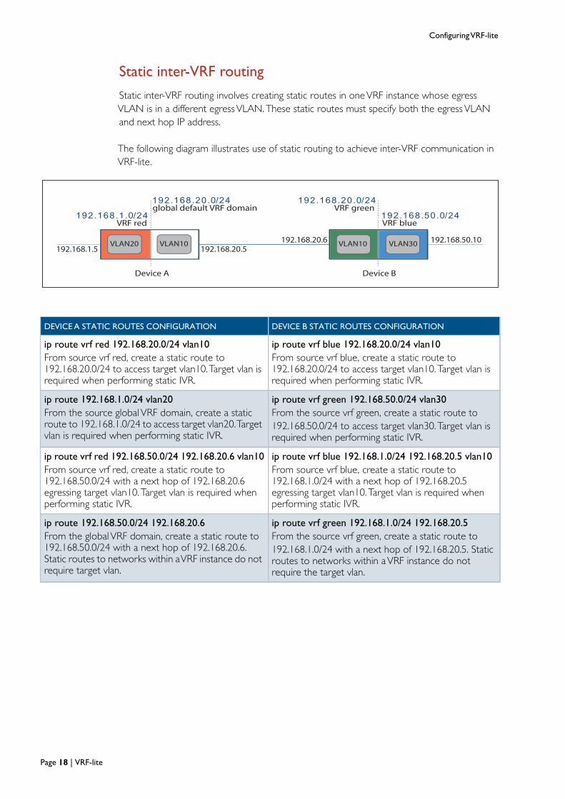
Configuring VRF-lite
Static inter-VRF routing
Static inter-VRF routing involves creating static routes in one VRF instance whose egress
VLAN is in a different egress VLAN. These static routes must specify both the egress VLAN
and next hop IP address.
192.168.1.0/24
192.168.20.0/24 192.168.20.0/24
192.168.50.0/24VRF red
VLAN20
global default VRF domain
VLAN10 VLAN10 VLAN30
VRF green
VRF blue
192.168.20.6192.168.20.5192.168.1.5
192.168.50.10
Device A Device B
The following diagram illustrates use of static routing to achieve inter-VRF communication inVRF-lite.
DEVICE A STATIC ROUTES CONFIGURATION DEVICE B STATIC ROUTES CONFIGURATION
ip route vrf red 192.168.20.0/24 vlan10
From source vrf red, create a static route to192.168.20.0/24 to access target vlan10.Target vlan isrequired when performing static IVR.
ip route vrf blue 192.168.20.0/24 vlan10
From source vrf blue, create a static route to192.168.20.0/24 to access target vlan10. Target vlan isrequired when performing static IVR.
ip route 192.168.1.0/24 vlan20
From the source global VRF domain, create a staticroute to 192.168.1.0/24 to access target vlan20.Targetvlan is required when performing static IVR.
ip route vrf green 192.168.50.0/24 vlan30
From the source vrf green, create a static route to192.168.50.0/24 to access target vlan30. Target vlan isrequired when performing static IVR.
ip route vrf red 192.168.50.0/24 192.168.20.6 vlan10
From source vrf red, create a static route to192.168.50.0/24 with a next hop of 192.168.20.6egressing target vlan10. Target vlan is required whenperforming static IVR.
ip route vrf blue 192.168.1.0/24 192.168.20.5 vlan10
From source vrf blue, create a static route to192.168.1.0/24 with a next hop of 192.168.20.5egressing target vlan10. Target vlan is required whenperforming static IVR.
ip route 192.168.50.0/24 192.168.20.6
From the global VRF domain, create a static route to192.168.50.0/24 with a next hop of 192.168.20.6.Static routes to networks within aVRF instance do notrequire target vlan.
ip route vrf green 192.168.1.0/24 192.168.20.5
From the source vrf green, create a static route to192.168.1.0/24 with a next hop of 192.168.20.5. Staticroutes to networks within aVRF instance do notrequire the target vlan.
Page 18 | VRF-lite

Dynamic inter-VRF Communication Explained
Dynamic inter-VRF Communication Explained
The following section explains how VRF routing domain isolation is maintained, and how
routes that exist in one VRF instance are leaked to another VRF instance via BGP. Only BGP
can be used to dynamically leak routes from one VRF instance to another.
VRF Device
VRF blueFIB
BGPaddress-
familyblue RIPaddress-
familyblueOSPF 2
VRF redFIB
BGPaddress-
familyred
RIPaddress-
familyred
OSPF 1
BGP routes copied between BGP
address-families to facilitate inter-VRF
communication
The Forwarding Information Base (FIB) and routing protocols
Associated with eachVRF instance is an IP route table, also known as the ForwardingInformation Base (FIB). When BGP address-families (associated withVRF instances) areconfigured, a corresponding BGP route table is created for eachVRF instance on which aBGP address-family is configured.
Similarly, when RIP address-families (associated withVRF instances) are configured, acorresponding RIP route table is created for eachVRF instance on which a RIP address-familyis configured.
Similarly, when OSPF instances (associated withVRF instances) are configured, acorresponding OSPF route table is created for eachVRF instance on which an OSPF instanceis configured.
Each dynamic routing protocol automatically selects appropriate routes and copies them tothe FIB.
Static and connected routes are automatically added to the FIB when they are created.
VRF-lite | Page 19

Dynamic inter-VRF Communication Explained
The command redistribute <protocol> can be configured in an OSPF instance, BGPaddress-family, or RIP address-family. Via this command, routes are imported from the FIBassociated with theVRF instance into the dynamic routing protocol table. Any routingprotocol (OSPF, BGP, RIP static, connected, etc.) can be redistributed.
For example, if OSPF instance1 is configured onVRF red, and if OSPF 1 contains thecommand redistribute BGP, then BGP routes will be copied fromVRF red FIB to OSPFinstance1.
Similarly, if BGP address-family is configured onVRF red, and if the address-family containsthe command redistribute OSPF, then OSPF instance1 routes will be copied from theVRF red FIB into the BGP red address-family route table.
Dual role ofBGP
The first role that BGP plays in aVRF-lite environment is to facilitate BGP peering to anexternal router operating within theVRF routing domain via the neighbor x.x.x.x commandconfigured in a BGP address-family.
The second role that BGP plays is to facilitate route leakage betweenVRF routing domains.
Dynamic routing protocols (RIP and OSPF) do not facilitate route leakage. RIP and OSPFonly operate within aVRF routing domain.
Page 20 | VRF-lite
Dynamic inter-VRF Communication Explained
VRF Device
Redistribute BGPfrom VRF red FIB
Redistribute OSPFfrom VRF red FIB
Redistribute BGPfrom VRF blue FIB
Redistribute OSPFfrom VRF blue FIB
BGPaddress-
familyblue
VRFblueFIB OSPF 2
BGPaddress-
familyred
OSPF 1
BGP routes copied between BGP
address-families to facilitate inter-VRF
communication
OSFP peer
router
OSFP peer
router
VRFredFIB
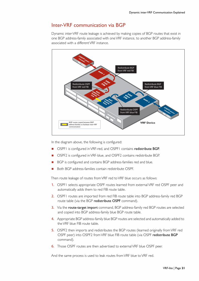
Inter-VRF communication via BGP
Dynamic inter-VRF route leakage is achieved by making copies of BGP routes that exist inone BGP address-family associated with oneVRF instance, to another BGP address-familyassociated with a differentVRF instance.
In the diagram above, the following is configured:
OSPF1 is configured inVRF-red, and OSPF1 contains redistribute BGP.
OSPF2 is configured inVRF-blue, and OSPF2 contains redistribute BGP.
BGP is configured and contains BGP address-families red and blue.
Both BGP address-families contain redistribute OSPF.
Then route leakage of routes fromVRF red toVRF blue occurs as follows:
1. OSPF1 selects appropriate OSPF routes learned from external VRF red OSPF peer andautomatically adds them to red FIB route table.
2. OSPF1 routes are imported from red FIB route table into BGP address-family red BGProute table (via the BGP redistribute OSPF command).
3. Via the route-target import command, BGP address-family red BGP routes are selectedand copied into BGP address-family blue BGP route table.
4. Appropriate BGP address-family blue BGP routes are selected and automatically added totheVRF blue FIB route table.
5. OSPF2 then imports and redistributes the BGP routes (learned originally fromVRF redOSPF peer) into OSPF2 fromVRF blue FIB route table (via OSPF redistribute BGP
command).
6. Those OSPF routes are then advertised to external VRF blue OSPF peer.
And the same process is used to leak routes fromVRF blue toVRF red.
VRF-lite | Page 21

Dynamic inter-VRF Communication Explained
Using the route-target command
When BGP is used for inter-VRF communication, dynamic route leakage of BGP routes fromoneVRF instance to another is achieved via theVRF route-target command.
There are three variations of the route-target command:
1. route-target export <ASN:VRFinstance>
for example:ip vrf redrd 100:1route-target export 100:1
2. route-target import <ASN:VRFinstance>
for example:ip vrf redrd 100:1route-target import 100:2
3. route-target both <ASN:VRFinstance>*
for example:ip vrf redrd 100:1route-target export 100:1route-target export 100:2route-target export 100:3route-target import 100:2
can be replaced with:ip vrf redrd 100:1route-target export 100:1route-target export 100:3route-target both 100:2
*Use of the command route-target both is uncommon in aVRF-lite environment.
The command route-target export applies a BGP extended community attribute to eachBGP prefix stored in the BGP route table of the address-family associated with theVRFinstance. The content of this attribute is the (ASN) that was specified in the route-target
export command.
Page 22 | VRF-lite

Dynamic inter-VRF Communication Explained
The following three examples demonstrate how the route-target command facilitates inter-VRF communication:
1. If VRF red configuration includes:ip vrf redrd 100:1route-target export 100:1
And ifVRF red initially has routes to networks 10.0.0.0/24, 20.0.0.0/24, then the entries in theaddress-family red BGP route table for each of those two routes would have the extended-community attribute applied as follows:10.0.0.0/24 100:120.0.0.0/24 100:1
Also, if VRF shared configuration includes:ip vrf sharedrd 100:2route-target import 100:1
thenVRF shared will check all otherVRFs’ BGP tables searching for routes with theextended-community attribute 100:1, and those specific routes will be copied into theVRFshared BGP route table from the otherVRFs, and they will be marked as copied BGP routes.
VRF shared will then have copied BGP routes that have been leaked fromVRF red:(copy)10.0.0.0/24 100:1(copy)20.0.0.0/24 100:1
2. If VRF red initially includes:ip vrf redrd 100:1route-target export 100:1route-target import 100:210.0.0.0/24 100:120.0.0.0/24 100:1
And if VRF shared initially includes:ip vrf sharedrd 100:2route-target export 100:2route-target import 100:130.0.0.0/24 100:240.0.0.0/24 100:2
Then via BGP inter-VRF routing (IVR), VRF red will end up with the routes:10.0.0.0/24 100:120.0.0.0/24 100:1(copy)30.0.0.0/24 100:2(copy)40.0.0.0/24 100:2
And via BGP IVR,VRF shared will end up with the routes:(copy)10.0.0.0/24 100:1(copy)20.0.0.0/24 100:130.0.0.0/24 100:240.0.0.0/24 100:2
EachVRF instance now contains dynamic inter-VRF routes.
VRF-lite | Page 23
Dynamic inter-VRF Communication Explained
3. If VRF red configuration includes*:ip vrf redrd 100:1route-target export 100:1route-target export 100:2route-target export 100:3route-target export 100:4route-target import 100:5route-target import 100:6
And if VRF red initially has routes to networks 10.0.0.0/24, 20.0.0.0/24, then each of thosetwo routes would have multiple extended community attributes (as defined in the route-
target export command configured in theVRF instance) as follows:10.0.0.0/24 100:1 100:2 100:3 100:420.0.0.0/24 100:1 100:2 100:3 100:4
And If VRF shared configuration includes:ip vrf sharedrd 100:5route-target export 100:5route-target import 100:2
And ifVRF shared initially has routes to networks 30.0.0.0/24, 40.0.0.0/24, then each of thosetwo routes would have an extended community attribute applied (as defined in the route-
target export command) as follows:30.0.0.0/24 100:540.0.0.0/24 100:5
Then via BGP IVR,VRF red will end up with the routes:10.0.0.0/24 100:1 100:2 100:3 100:420.0.0.0/24 100:1 100:2 100:3 100:4(copy)30.0.0.0/24 100:5(copy)40.0.0.0/24 100:5
And via BGP IVR,VRF shared will end up with the routes:(copy)10.0.0.0/24 100:1 100:2 100:3 100:4(copy)20.0.0.0/24 100:1 100:2 100:3 100:430.0.0.0/24 100:540.0.0.0/24 100:5
*Use of the command route-target export, as per example 3 above, to tag routes in aVRFinstance with ASNs associated with otherVRF instances is uncommon in aVRF-liteenvironment.
Page 24 | VRF-lite
Dynamic inter-VRF Communication Explained
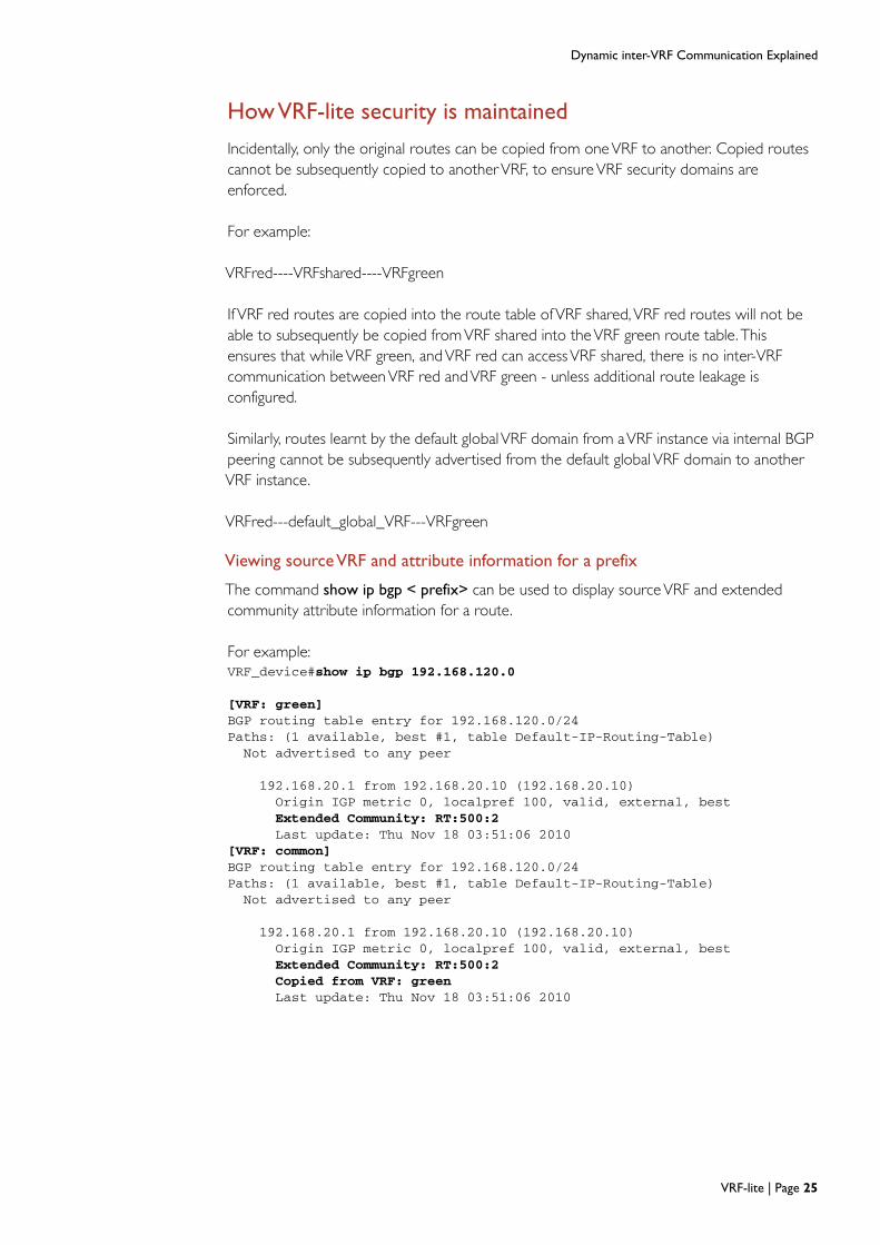
How VRF-lite security is maintained
Incidentally, only the original routes can be copied from oneVRF to another. Copied routescannot be subsequently copied to anotherVRF, to ensureVRF security domains areenforced.
For example:
VRFred----VRFshared----VRFgreen
If VRF red routes are copied into the route table ofVRF shared,VRF red routes will not beable to subsequently be copied fromVRF shared into theVRF green route table. Thisensures that whileVRF green, andVRF red can accessVRF shared, there is no inter-VRFcommunication betweenVRF red andVRF green - unless additional route leakage isconfigured.
Similarly, routes learnt by the default globalVRF domain from aVRF instance via internal BGPpeering cannot be subsequently advertised from the default global VRF domain to anotherVRF instance.
VRFred---default_global_VRF---VRFgreen
Viewing source VRF and attribute information for a prefix
The command show ip bgp < prefix> can be used to display sourceVRF and extendedcommunity attribute information for a route.
For example:VRF_device#show ip bgp 192.168.120.0
[VRF: green]BGP routing table entry for 192.168.120.0/24Paths: (1 available, best #1, table Default-IP-Routing-Table)Not advertised to any peer
192.168.20.1 from 192.168.20.10 (192.168.20.10)Origin IGP metric 0, localpref 100, valid, external, bestExtended Community: RT:500:2Last update: Thu Nov 18 03:51:06 2010
[VRF: common]BGP routing table entry for 192.168.120.0/24Paths: (1 available, best #1, table Default-IP-Routing-Table)Not advertised to any peer
192.168.20.1 from 192.168.20.10 (192.168.20.10)Origin IGP metric 0, localpref 100, valid, external, bestExtended Community: RT:500:2Copied from VRF: greenLast update: Thu Nov 18 03:51:06 2010
VRF-lite | Page 25

Simple VRF-lite Configuration Examples
Simple VRF-lite Configuration Examples
The following section contains simple configuration examples to explain the basics ofVRF-liteconfiguration used in conjunction with a variety of routing protocols.
Firstly, always create a clearVRF communication plan. This includes researching the variousrouting protocols and likely IP network plans for eachVRF, and the likely content of eachVRFrouting table. Also confirm any overlapping IP address space requirements, and if there areany inter-VRF communication requirements.
Multiple VRFs without inter-VRF communication
The partial configuration example below shows the key components required to support
multiple VRF instances with OSPF peering to external neighbors within each VRF instance.
There is no inter-VRF communication used in this first example.
PC1
vlan 14
Customer1 (VRF red)
vlan 13
vlan 12
vlan 11
PC2
PC3
PC4
VRF
R1
R2
R4
R3
Customer2 (VRF green)
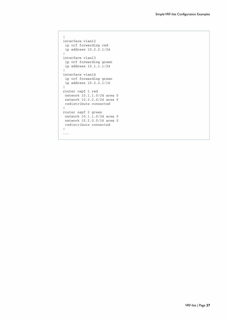
...!ip vrf reddescription Customer1!ip vrf greendescription Customer2!interface vlan11ip vrf forwarding redip address 10.1.1.1/24[cont...]
Two interfaces, vlan11 and vlan12 are configured for Customer1 (VRF red), and two otherinterfaces, vlan13 and vlan14 are configured for Customer2 (VRF green). In this example,overlapping IP addresses are used. OSPF is used as the routing protocol within each VRFinstance.
Page 26 | VRF-lite
Simple VRF-lite Configuration Examples
!interface vlan12ip vrf forwarding redip address 10.2.2.1/24!interface vlan13ip vrf forwarding greenip address 10.1.1.1/24!interface vlan14ip vrf forwarding greenip address 10.2.2.1/16!router ospf 1 rednetwork 10.1.1.0/24 area 0network 10.2.2.0/24 area 0redistribute connected!router ospf 2 greennetwork 10.1.1.0/24 area 0network 10.2.0.0/16 area 0redistribute connected!...
VRF-lite | Page 27

Simple VRF-lite Configuration Examples
VRFs accessing a shared network. An example of static inter-VRF routing
100.100.100.0/24
- Inter VRF (IVR) communications
via static IVR routes
VRF red
VRF green
Global default
VRF domain
vlan 100
1.20.1.0/24
vlan 14
1.10.1.0/24
vlan 12
...!ip vrf red!ip vrf green!interface vlan12ip vrf forwarding redip address 1.10.1.1/24!interface vlan14ip vrf forwarding greenip address 1.20.1.1/24!interface vlan100ip address 100.100.100.100/24!ip route vrf red 0.0.0.0/0 vlan100ip route vrf green 0.0.0.0/0 vlan100ip route 1.10.1.0/24 vlan12ip route 1.20.1.0/24 vlan14!...
The partial configuration example below shows the key components required to supportstatic inter-VRF routing.
Two companies (VRF red andVRF green) are able to access shared vlan100. Shared vlan100exists in the Global default VRF. Static inter-VRF routing is used in this example to facilitateinter-VRF communication. There are no overlapping IP addresses. As there is no externalrouter in vlan100 and there is no Internet access via vlan100, ACLs are not required.
Page 28 | VRF-lite

Simple VRF-lite Configuration Examples
...!ip vrf redrd 100:1route-target export 100:1route-target import 100:2!ip vrf greenrd 100:2route-target export 100:2route-target import 100:1!router rip!address-family ipv4 vrf rednetwork vlan20redistribute bgpexit-address-family!address-family ipv4 vrf greennetwork vlan60redistribute bgpexit-address-family!router bgp 100address-family ipv4 vrf redredistribute connectedredistribute ripexit-address-family!address-family ipv4 vrf greenredistribute connectedredistribute ripexit-address-family!...
Dynamic inter-VRF communication with RIP routing to external peers
The partial configuration example below shows the key components required to supportdynamic inter-VRF communication between twoVRF instances using BGP, with RIP routing toexternal peers.
RIP address-families are created, and each RIP address-family is associated with aVRFinstance. To achieve inter-VRF communications, BGP is redistributed into each RIP family.Conversely, BGP address-families are created and each BGP address-family is associated withaVRF instance, and RIP is redistributed into each BGP address-family. Connected routes arealso redistributed into BGP to be leaked betweenVRF instances.
VRF-lite | Page 29

Simple VRF-lite Configuration Examples
...!ip vrf redrd 100:1route-target export 100:1route-target import 100:2!ip vrf greenrd 100:2route-target export 100:2route-target import 100:1!router bgp 100!address-family ipv4 vrf redredistribute connectedneighbor 1.1.1.1 remote-as 100neighbor 1.1.1.1 activateexit-address-family!address-family ipv4 vrf greenneighbor 2.2.2.2 remote-as 200neighbor 2.2.2.2 activateredistribute connectedexit-address-family!...
Dynamic inter-VRF communication with BGP routing to external peers
The partial configuration example below shows the key components required to supportdynamic inter-VRF communication using BGP, with BGP routing to external peers.
BGP address-families are created. Each BGP address-family is associated with aVRF instance.Routes within theVRF domain are advertised to external BGP peers. Selected BGP routes(including connected routes redistributed into BGP, and BGP routes learned from externalBGP neighbors) are copied betweenVRF instances.
Page 30 | VRF-lite
Simple VRF-lite Configuration Examples
redrouter
192.168.35.0/24
vlan 1
OSPF1
192.168.10.0/24
OSPF2
192.168.20.0/24
192.168.30.0/24 192.168.33.0/24
192.168.34.0/24
- Inter VRF (IVR) communications
via Route leakage
VRF red100:1
VRF green100:2
VRF shared100:3
greenrouter
vlan 2
sharedrouter
vlan 3
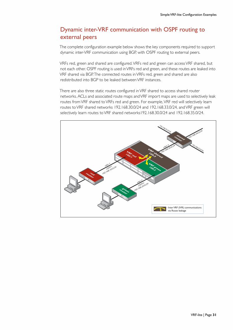
Dynamic inter-VRF communication with OSPF routing to external peers
The complete configuration example below shows the key components required to supportdynamic inter-VRF communication using BGP, with OSPF routing to external peers.
VRFs red, green and shared are configured.VRFs red and green can accessVRF shared, butnot each other. OSPF routing is used inVRFs red and green, and these routes are leaked intoVRF shared via BGP.The connected routes inVRFs red, green and shared are alsoredistributed into BGP to be leaked betweenVRF instances.
There are also three static routes configured inVRF shared to access shared routernetworks. ACLs and associated route maps andVRF import maps are used to selectively leakroutes fromVRF shared toVRFs red and green. For example, VRF red will selectively learnroutes toVRF shared networks 192.168.30.0/24 and 192.168.33.0/24, andVRF green willselectively learn routes toVRF shared networks192.168.30.0/24 and 192.168.35.0/24.
VRF-lite | Page 31

Simple VRF-lite Configuration Examples
!access-list standard greenBlock3334 deny 192.168.33.0/24access-list standard greenBlock3334 deny 192.168.34.0/24access-list standard greenBlock3334 permit anyaccess-list standard redBlock3435 deny 192.168.34.0/24access-list standard redBlock3435 deny 192.168.35.0/24access-list standard redBlock3435 permit any!ip vrf redrd 100:1route-target export 100:1route-target import 100:3import map red33!ip vrf greenrd 100:2route-target export 100:2route-target import 100:3import map green35!ip vrf sharedrd 100:3route-target import 100:1route-target import 100:2route-target export 100:3!vlan databasevlan 2-3 state enable!interface port1.0.1switchportswitchport mode access!interface port1.0.2switchportswitchport mode accessswitchport access vlan 2!interface port1.0.3switchportswitchport mode accessswitchport access vlan 3!interface port1.0.4-1.0.26switchportswitchport mode access![cont...]
Page 32 | VRF-lite

Simple VRF-lite Configuration Examples
interface vlan1ip vrf forwarding redip address 192.168.10.1/24!interface vlan2ip vrf forwarding greenip address 192.168.20.1/24!interface vlan3ip vrf forwarding sharedip address 192.168.30.1/24!router ospf 1 rednetwork 192.168.10.0/24 area 0redistribute bgp!router ospf 2 greennetwork 192.168.20.0/24 area 0redistribute bgp!router bgp 100 address-family ipv4 vrf red redistribute ospf redistribute connected exit-address-family ! address-family ipv4 vrf green redistribute ospf redistribute connected exit-address-family ! address-family ipv4 vrf shared redistribute staticredistribute connected exit-address-family!ip route vrf shared 192.168.33.0/24 192.168.30.3ip route vrf shared 192.168.34.0/24 192.168.30.3ip route vrf shared 192.168.35.0/24 192.168.30.3!route-map red33 permit 1 match ip address redBlock3435!route-map green35 permit 1 match ip address greenBlock3334!line con 0line vty 0 4!end
VRF-lite | Page 33
Inter-VRF Configuration Examples with Internet Access
Inter-VRF Configuration Examples with Internet Access
The following three complete examples are using a similar topology, however, each exampleinvolves a different communication plan and a variety of routing protocols. All of thefollowing examples utilize one or more Internet connections.
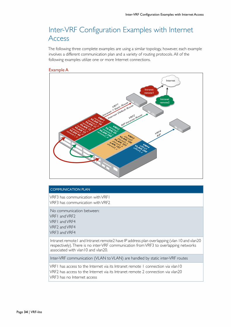
Example A
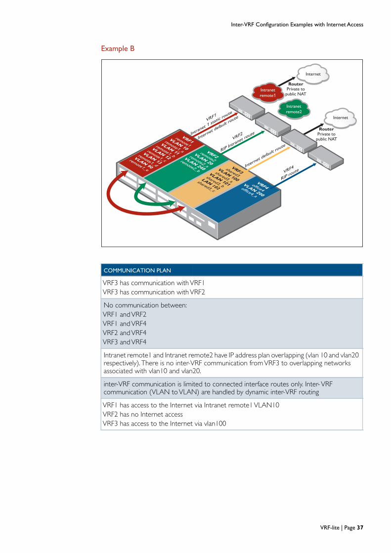
COMMUNICATION PLAN
VRF3 has communication withVRF1VRF3 has communication withVRF2
No communication between:VRF1 andVRF2VRF1 andVRF4VRF2 andVRF4VRF3 andVRF4
Intranet remote1 and Intranet remote2 have IP address plan overlapping (vlan 10 and vlan20respectively). There is no inter-VRF communication fromVRF3 to overlapping networksassociated with vlan10 and vlan20.
Inter-VRF communication (VLAN toVLAN) are handled by static inter-VRF routes
VRF1 has access to the Internet via its Intranet remote 1 connection via vlan10VRF2 has access to the Internet via its Intranet remote 2 connection via vlan20VRF3 has no Internet access
Internet
Intranet
remote1
VRF1
Intranet 1 St
atic R
oute
Intranet
remote2
Internet D
efault R
oute
VRF2
RIP Intra
net Route
VRF4
RIP
VRF1remote1
VLAN 10remote1_a
VLAN 11remote1_b
VLAN 12remote1_c
VLAN 13remote1_d
VLAN 90remote1_e
VRF2remote2
VLAN 20remote2_a
VLAN 248remote2_b
VRF3shared3
VLAN 100shared3_a
VLAN 101shared3_b
LAN 102shared3_c
VRF4office4VLAN 200
office4_a
Page 34 | VRF-lite

Inter-VRF Configuration Examples with Internet Access
Configuration!ip vrf remote1 1!ip vrf remote2 2!ip vrf shared3 3!ip vrf office4 4!vlan databasevlan 10 name remote1_avlan 11 name remote1_bvlan 12 name remote1_cvlan 13 name remote1_dvlan 20 name remote2_avlan 90 name remote1_evlan 100 name shared3_avlan 101 name shared3_bvlan 102 name shared3_cvlan 200 name office4_avlan 248 name remote2_bvlan 10-13,20,90,100-102,200,248 state enable!interface port1.0.1switchportswitchport mode trunkswitchport trunk allowed vlan add 10-13,90!interface port1.0.2switchportswitchport mode trunkswitchport trunk allowed vlan add 20,248!interface port1.0.3switchportswitchport mode trunkswitchport trunk allowed vlan add 100-102!interface port1.0.4switchportswitchport mode trunkswitchport trunk allowed vlan add 200!interface port1.0.5switchportswitchport mode accessswitchport access vlan 100!interface port1.0.6-1.0.26switchportswitchport mode access!interface vlan10ip vrf forwarding remote1ip address 10.0.0.1/8!interface vlan11ip vrf forwarding remote1ip address 11.0.0.1/8!interface vlan12ip vrf forwarding remote1
VRF-lite | Page 35

Inter-VRF Configuration Examples with Internet Access
ip address 12.0.0.1/8!interface vlan13ip vrf forwarding remote1ip address 13.0.0.1/8!interface vlan20ip vrf forwarding remote2ip address 10.0.0.1/8!interface vlan90ip vrf forwarding remote1ip address 14.0.0.1/8!interface vlan100ip vrf forwarding shared3ip address 30.0.0.1/8!interface vlan101ip vrf forwarding shared3ip address 31.0.0.1/8!interface vlan102ip vrf forwarding shared3ip address 32.0.0.1/8!interface vlan200ip vrf forwarding office4ip address 40.0.0.1/8!interface vlan248ip vrf forwarding remote2ip address 20.0.0.1/8!router rip!address-family ipv4 vrf remote2network vlan20redistribute connectedexit-address-family!address-family ipv4 vrf office4network vlan200exit-address-family!ip route vrf remote1 0.0.0.0/0 10.0.0.2ip route vrf remote1 30.0.0.0/8 vlan100ip route vrf remote1 31.0.0.0/8 vlan101ip route vrf remote1 32.0.0.0/8 vlan102ip route vrf remote1 80.0.0.0/8 10.0.0.2ip route vrf remote2 0.0.0.0/0 10.0.0.2ip route vrf remote2 30.0.0.0/8 vlan100ip route vrf remote2 31.0.0.0/8 vlan101ip route vrf remote2 32.0.0.0/8 vlan102ip route vrf shared3 11.0.0.0/8 vlan11ip route vrf shared3 12.0.0.0/8 vlan12ip route vrf shared3 13.0.0.0/8 vlan13ip route vrf shared3 14.0.0.0/8 vlan90ip route vrf shared3 20.0.0.0/8 vlan248!line con 0line vty 0 4!end
Page 36 | VRF-lite
Inter-VRF Configuration Examples with Internet Access
Internet
Intranet
remote1
VRF1
Intranet 1 st
atic r
oute
Intranet
remote2
Internet d
efault r
oute
VRF2
RIP Intra
net route
VRF4
RIP ro
ute
Internet
RouterPrivate to
public NAT
RouterPrivate to
public NAT
Internet d
efault r
oute
VRF1remote1
VLAN 10remote1_a
VLAN 11remote1_b
VLAN 12remote1_c
VLAN 13remote1_d
VLAN 90
remote1_e
VRF2remote2
VLAN 20remote2_a
VLAN 248remote2_b
VRF3shared3
VLAN 100shared3_a
VLAN 101shared3_b
LAN 102shared3_c
VRF4office4VLAN 200
office4_a
COMMUNICATION PLAN
VRF3 has communication withVRF1VRF3 has communication withVRF2
No communication between:VRF1 andVRF2VRF1 andVRF4VRF2 andVRF4VRF3 andVRF4
Intranet remote1 and Intranet remote2 have IP address plan overlapping (vlan 10 and vlan20respectively). There is no inter-VRF communication fromVRF3 to overlapping networksassociated with vlan10 and vlan20.
inter-VRF communication is limited to connected interface routes only. Inter-VRFcommunication (VLAN toVLAN) are handled by dynamic inter-VRF routing
VRF1 has access to the Internet via Intranet remote1VLAN10VRF2 has no Internet accessVRF3 has access to the Internet via vlan100
Example B
VRF-lite | Page 37
Inter-VRF Configuration Examples with Internet Access
Configuration!access-list standard deny_overlap deny 10.0.0.0/8access-list standard deny_overlap permit any!ip vrf remote1 1rd 100:1route-target export 100:1route-target import 100:3export map block10!ip vrf remote2 2rd 100:2route-target export 100:2route-target import 100:3export map block10!ip vrf shared3 3rd 100:3route-target import 100:1route-target import 100:2route-target export 100:3!ip vrf office4!vlan databasevlan 10 name remote1_avlan 11 name remote1_bvlan 12 name remote1_cvlan 13 name remote1_dvlan 20 name remote2_avlan 90 name remote1_evlan 100 name shared3_avlan 101 name shared3_bvlan 102 name shared3_cvlan 200 name office4_avlan 248 name remote2_bvlan 10-13,20,90,100-102,200,248 state enable!interface port1.0.1switchportswitchport mode trunkswitchport trunk allowed vlan add 10-13,90!interface port1.0.2switchportswitchport mode trunkswitchport trunk allowed vlan add 20,248!interface port1.0.3switchportswitchport mode trunkswitchport trunk allowed vlan add 100-102!interface port1.0.4switchportswitchport mode trunkswitchport trunk allowed vlan add 200!interface port1.0.5switchportswitchport mode accessswitchport access vlan 100!
Page 38 | VRF-lite

Inter-VRF Configuration Examples with Internet Access
interface port1.0.6-1.0.26switchportswitchport mode access!interface vlan10ip vrf forwarding remote1ip address 10.0.0.1/8!interface vlan11ip vrf forwarding remote1ip address 11.0.0.1/8!interface vlan12ip vrf forwarding remote1ip address 12.0.0.1/8!interface vlan13ip vrf forwarding remote1ip address 13.0.0.1/8!interface vlan20ip vrf forwarding remote2ip address 10.0.0.1/8!interface vlan90ip vrf forwarding remote1ip address 14.0.0.1/8!interface vlan100ip vrf forwarding shared3ip address 30.0.0.1/8!interface vlan101ip vrf forwarding shared3ip address 31.0.0.1/8!interface vlan102ip vrf forwarding shared3ip address 32.0.0.1/8!interface vlan200ip vrf forwarding office4ip address 40.0.0.1/8!interface vlan248ip vrf forwarding remote2ip address 20.0.0.1/8!router rip!address-family ipv4 vrf remote2network vlan20redistribute connectedexit-address-family!address-family ipv4 vrf office4network vlan200exit-address-family!router bgp 100address-family ipv4 vrf remote1redistribute connectedexit-address-family!
VRF-lite | Page 39
Inter-VRF Configuration Examples with Internet Access
address-family ipv4 vrf remote2redistribute connectedexit-address-family!address-family ipv4 vrf shared3redistribute connectedexit-address-family!ip route vrf remote1 0.0.0.0/0 10.0.0.2ip route vrf shared3 0.0.0.0/0 30.0.0.2ip route vrf remote1 80.0.0.0/8 10.0.0.2!route-map block10 permit 1match ip address deny_overlap!
Additional note:
If VRF remote2 needs to have its own Internet access via vlan20, either :
add a static default route into this device:
ip route vrf remote2 0.0.0.0/0 10.0.0.2
Or
Configure Intranet remote2 RIP peer with default-originate (redistribute default route toRIP peer) and hence ensure Intranet remote2 RIP peer advertises the default route viaRIP to thisVRF aware device.
Page 40 | VRF-lite
Inter-VRF Configuration Examples with Internet Access
Example C
Intranet
remote1
VRF1
Intranet 1 st
atic r
oute
Intranet
remote2
Internet d
efault r
oute
VRF2
RIP Intra
net route
VRF4
RIP ro
ute
Internet
RouterPrivate to
public NATVRF1
remote1VLAN 10
remote1_a
VLAN 11remote1_b
VLAN 12remote1_c
VLAN 13remote1_d
VLAN 90
remote1_e
VRF2remote2
VLAN 20remote2_a
VLAN 248remote2_b
VRF3shared3
VLAN 100shared3_a
VLAN 101shared3_b
LAN 102shared3_c
VRF4office4VLAN 200
office4_a
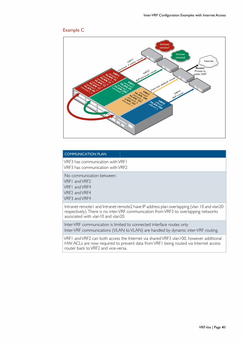
COMMUNICATION PLAN
VRF3 has communication withVRF1VRF3 has communication withVRF2
No communication between:VRF1 andVRF2VRF1 andVRF4VRF2 andVRF4VRF3 andVRF4
Intranet remote1 and Intranet remote2 have IP address plan overlapping (vlan 10 and vlan20respectively). There is no inter-VRF communication fromVRF3 to overlapping networksassociated with vlan10 and vlan20.
Inter-VRF communication is limited to connected interface routes only.Inter-VRF communications (VLAN toVLAN) are handled by dynamic inter-VRF routing.
VRF1 andVRF2 can both access the Internet via sharedVRF3 vlan100, however additionalHW ACLs are now required to prevent data fromVRF1 being routed via Internet accessrouter back toVRF2 and vice-versa.
VRF-lite | Page 41

Inter-VRF Configuration Examples with Internet Access
Configuration!access-list standard deny_overlap deny 10.0.0.0/8access-list standard deny_overlap permit any!ip vrf remote1 1rd 100:1route-target export 100:1route-target import 100:3export map block10!ip vrf remote2 2rd 100:2route-target export 100:2route-target import 100:3export map block10!ip vrf shared3 3rd 100:3route-target import 100:1route-target import 100:2route-target export 100:3!ip vrf office4 4!access-list hardware deny_to_vrf1deny ip any 11.0.0.0/8deny ip any 12.0.0.0/8deny ip any 13.0.0.0/8deny ip any 14.0.0.0/8access-list hardware deny_to_vrf2deny ip any 20.0.0.0/8!vlan databasevlan 10 name remote1_avlan 11 name remote1_bvlan 12 name remote1_cvlan 13 name remote1_dvlan 20 name remote2_avlan 90 name remote1_evlan 100 name shared3_avlan 101 name shared3_bvlan 102 name shared3_cvlan 200 name office4_avlan 248 name remote2_bvlan 10-13,20,90,100-102,200,248 state enable!interface port1.0.1switchportswitchport mode trunkswitchport trunk allowed vlan add 10-13,90access-group deny_to_vrf2!interface port1.0.2switchportswitchport mode trunkswitchport trunk allowed vlan add 20,248access-group deny_to_vrf1!interface port1.0.3switchportswitchport mode trunkswitchport trunk allowed vlan add 100-102!
Page 42 | VRF-lite

Inter-VRF Configuration Examples with Internet Access
interface port1.0.4switchportswitchport mode trunkswitchport trunk allowed vlan add 200!interface port1.0.5switchportswitchport mode accessswitchport access vlan 100!interface port1.0.6-1.0.26switchportswitchport mode access!interface vlan10ip vrf forwarding remote1ip address 10.0.0.1/8!interface vlan11ip vrf forwarding remote1ip address 11.0.0.1/8!interface vlan12ip vrf forwarding remote1ip address 12.0.0.1/8!interface vlan13ip vrf forwarding remote1ip address 13.0.0.1/8!interface vlan20ip vrf forwarding remote2ip address 10.0.0.1/8!interface vlan90ip vrf forwarding remote1ip address 14.0.0.1/8!interface vlan100ip vrf forwarding shared3ip address 30.0.0.1/8!interface vlan101ip vrf forwarding shared3ip address 31.0.0.1/8!interface vlan102ip vrf forwarding shared3ip address 32.0.0.1/8!interface vlan200ip vrf forwarding office4ip address 40.0.0.1/8!interface vlan248ip vrf forwarding remote2ip address 20.0.0.1/8!router rip!address-family ipv4 vrf remote2network vlan20redistribute connectedexit-address-family
VRF-lite | Page 43

Inter-VRF Configuration Examples with Internet Access
!address-family ipv4 vrf office4network vlan200exit-address-family!router bgp 100address-family ipv4 vrf remote1redistribute connectedexit-address-family!address-family ipv4 vrf remote2redistribute connectedexit-address-family!address-family ipv4 vrf shared3redistribute connectedexit-address-family!ip route vrf remote1 0.0.0.0/0 30.0.0.2 vlan100ip route vrf remote2 0.0.0.0/0 30.0.0.2 vlan100ip route vrf shared3 0.0.0.0/0 30.0.0.2ip route vrf remote1 80.0.0.0/8 10.0.0.2!route-map block10 permit 1match ip address deny_overlap
Page 44 | VRF-lite

Configuring a Complex Inter-VRF Solution
Configuring a Complex Inter-VRF Solution
VRF overlap
L06=6.6.6.6VRF red
L01=1.1.1.1
OSPF-1 VRF green
L02=2.2.2.2
i-BGPVRF blue
L03=3.3.3.3RIP VRF orange
L04=4.4.4.4
OSPF-2
VRF shared
L05=5.5.5.5e-BGP
VRF-aware
device
i-BGP peer
router
RIP peer
router
OSFP peer
router
orangerouter
sharedrouter
e-BGPInternet
peer router
192.168.13.0/24
192.168.14.0/24
Internet
vlan 1192.168.10.0/24
vlan 2
192.168.20.0/24
OSFP peer
router
vlan 7192.168.50.0/24
vlan 6192.168.10.0/24
vlan 5192.168.100.0/24
192.168.15.0/24
192.168.16.0/24
vlan 3
192.168.30.0/24
192.168.17.0/24192.168.18.0/24
vlan 4
192.168.40.0/24
192.168.19.0/24
192.168.20.0/24
192.168.140.0/24
192.168.43.0/24
192.168.44.0/24192.168.45.0/24
Red type - over lapping IP address ranges
- Inter VRF (IVR) communications
via Route leakage
A network comprising of multiple devices that demonstrates inter-VRF routing. A variety ofrouting protocols are used in this example.
Network description
TheVRF-aware device has six separateVRFs configured, they are named: red, green, blue,orange, shared and overlap. TheVRF-aware device has static routes to two router networks(orange router and shared router). It also peers to two OSPF routers (OSPF red peer andOSPF orange peer), one i-BGP peer (i-BGP green peer) and one RIPv2 peer (RIP blue peer),and one e-BGP peer (e-BGP shared Internet peer) that allows Internet access. None of thepeer devices areVRF aware. Dynamic inter-VRF communication allows selectedVRFs toaccess a common shared Internet connection.
EachVLAN(s) is associated with aVRF instance.
EachVRF instance also has its own unique IP local interface and associated local IP address.
EachVRF contains its own separate IP routing domain and separate (OSPF) routingprotocol instance or (BGP/RIP) address-family.
TheVRF instances red, green, blue, and orange, are all able to access the Internet viaVRFshared.They also have filtered access to ‘shared router’ subnets. All inter-VRF communicationbetweenVRFs red, green, blue, and orange is blocked.
BGP, route-maps, and Access Control Lists (ACLs) are used to ‘leak’ selected routes betweenVRFs to allow filtered inter-VRF (IVR) communication.
VRF-lite | Page 45
Configuring a Complex Inter-VRF Solution
VRF communication plan
VRF shared can access all VRFs red, green, blue and orange (excludingVRF overlap).
VRFs red, green, blue, and orange are only able to accessVRF shared.They cannot accesseach other in this example.
VRF overlap remains completely isolated from all otherVRFs, and it has a connected routeto subnet 192.168.10.0/24, which is also configured inVRF red. No routes are exportedfrom or imported toVRF overlap, ensuring there is no IP address range overlap conflictwhen performing inter-VRF communication.
VRF red can access the Internet, andVRF shared subnets, 192.168.100.0/24, 192.168.43.0/24, butVRF red cannot accessVRF shared subnets 192.168.44.0/24, 192.168.45.0/24.
VRF red has a connected route to subnet 192.168.10.0/24, which is also configured inVRFoverlap. This connected route inVRF red is leaked to otherVRFs.
VRF green can access the Internet, andVRF shared subnets, 192.168.100.0/24,192.168.44.0/24, butVRF green cannot accessVRF shared subnets 192.168.43.0/24,192.168.45.0/24.
VRF green has a connected route to subnet 192.168.20.0/24, which overlaps a static routeconfigured inVRF orange. This connected route inVRF green is leaked to otherVRFs.
VRF blue can access the Internet, andVRF shared subnets, 192.168.100.0/24,192.168.45.0/24, butVRF blue cannot accessVRF shared subnets 192.168.43.0/24,192.168.44.0/24.
VRF orange can access the Internet, and can also access all VRF shared subnets,192.168.100.0/24, 192.168.43.0/24,192.168.44.0/24, 192.168.45.0/24.
VRF orange has static route to subnet 192.168.20.0/24, which overlaps a connected routeconfigured inVRF green. Therefore this subnet is not leaked fromVRF orange to otherVRF instances, ensuring there is no IP address range overlap conflict when performinginter-VRF communication.
Page 46 | VRF-lite

Configuring a Complex Inter-VRF Solution
CONFIGURE STANDARD ACLS
Configuration breakdown
When configuring a complex inter-VFR aware device, such as in our example, theconfiguration order is important. We have provided a breakdown before each step toexplain the key points you will need to consider.
Configure the standard ACLs
These standard ACL's are associated with routes maps. The route maps are referenced byVRF import and export maps. VRF export maps filter routes exported to BGP.VRF importmaps filter routes imported into theVRF domain from BGP. BGP is used to leak routesbetweenVRFs.
These ACLs should be configured before any inter-VRF communication is configured, toprevent unnecessary routes from being leaked from oneVRF to another.
Configure the VRFs
Next we configure the six numberedVRFs named red, green, blue, orange, shared andoverlap, via the command ip vrf-name number
The optional number parameter creates and assigns a local interface (LO) to theVRFinstance. This number parameter allows the user to manually control which local interface isassociated with eachVRF. If not specified, a local interface is automatically created andassigned to theVRF instance in the order ofVRF creation. Once an LO is created, it remainsassigned to theVRF (including over a reboot), unless manually changed by the user.
Only a single local interface perVRF is supported, and each local interface can be configuredwith its own local ip address.
A local interface (also referred to as an internal loopback interface) is an internal interfacethat is always available for higher layer protocols to use and advertise to the network.Although a local interface is assigned an IP address, it does not have the usual requirement ofconnecting to a lower layer physical entity.
awplus#conf t
Enter configuration commands, one per line. End with CNTL/Z.
awplus(config)#access-list standard blueBlock4344 deny 192.168.43.0/24
awplus(config)#access-list standard blueBlock4344 deny 192.168.44.0/24
awplus(config)#access-list standard blueBlock4344 permit any
awplus(config)#access-list standard greenBlock4345 deny 192.168.43.0/24
awplus(config)#access-list standard greenBlock4345 deny 192.168.45.0/24
awplus(config)#access-list standard greenBlock4345 permit any
awplus(config)#access-list standard orangeBlock20Export140 deny 192.168.20.0/24
awplus(config)#access-list standard orangeBlock20Export140 permit any
awplus(config)#access-list standard orangeNoBlock permit any
awplus(config)#access-list standard redBlock4445 deny 192.168.44.0/24
awplus(config)#access-list standard redBlock4445 deny 192.168.45.0/24
awplus(config)#access-list standard redBlock4445 permit any
VRF-lite | Page 47
Configuring a Complex Inter-VRF Solution
Local interfaces can be utilized by a number of protocols for various purposes. They can beused as a reliable address via which to access a device - an address that is always accessible,irrespective of the link status of any individual external interface.
Within eachVRF, configure optional route distinguisher (RD), route-targets andVRF importand export maps. The RD, route-targets andVRF import and export maps are used whenleaking routes via BGP.They are not required when inter-VRF communication is achieved viastatic inter-VRF routes. BGP is used to facilitate inter-VRF communication in this example.
The RD is a BGP ASN (xxx:). TheVRF RD is also used by MPLS to facilitateVRFVPNs,which are currently not supported, and thus serves little purpose in the context ofVRF-lite.However the RD command is required if using BGP to facilitate inter-VRF communications.Each RD references a uniqueVRF instance (:xxx). A completeVRF ASN uses the syntaxxxx:xxx. For example 100:1 denotes BGP ASN 100,VRF instance1.
The command route-target export xxx:xxx enables routes in theVRF domain with amatchingVRF ASN tag to be exported via BGP to be subsequently leaked to otherVRFs.
The command route-target import xxx:xxx enables routes from otherVRF domains with amatchingVRF ASN tag to be imported via BGP into theVRF domain.
The command export map name references a route map, which in turn references the ACLspreviously configured. This command ensures (via the associated ACLs) that only selectedroutes are exported from theVRF domain to BGP.
In this exampleVRF orange has a static route to network 192.168.20.0/24. This same IPsubnet is assigned to vlan 2, which is a part ofVRF green. Therefore there is an export map(orange 140) and associated ACL orangeBlock20Export140 deny 192.168.20.0/24 to ensurethe network 192.168.20.0 is not exported into BGP, whilst still allowing the export of othernetworks that do not match the ACL.
The command import map name references a route map, which in turn references the ACLspreviously configured. This commands ensures (via the associated ACLs) that only selectedroutes are imported into theVRF domain from BGP.
There is no route leakage to or fromVRF overlap. VRF overlap (and its associatedVLANs)remain completely isolated from all otherVRF domains. VRF overlap contains network192.168.10.0/24 associated with vlan6. This same subnet is also contained inVRF red vlan1.This is OK, asVRF overlap has no associated route-target import and route-target export
commands.
Page 48 | VRF-lite

Configuring a Complex Inter-VRF Solution
CONFIGUREVRFS
awplus(config)#ip vrf red 1
awplus(config-vrf)#rd 100:1
awplus(config-vrf)#route-target export 100:1
awplus(config-vrf)#route-target import 100:5
awplus(config-vrf)#import map red43
awplus(config-vrf)#exit
awplus(config)#ip vrf green 2
awplus(config-vrf)#rd 100:2
awplus(config-vrf)#route-target export 100:2
awplus(config-vrf)#route-target import 100:5
awplus(config-vrf)#import map green44
awplus(config-vrf)#exit
awplus(config)#ip vrf blue 3
awplus(config-vrf)#rd 100:3
awplus(config-vrf)#route-target export 100:3
awplus(config-vrf)#route-target import 100:5
awplus(config-vrf)#import map blue45
awplus(config-vrf)#exit
awplus(config)#ip vrf orange 4
awplus(config-vrf)#rd 100:4
awplus(config-vrf)#route-target export 100:4
awplus(config-vrf)#route-target import 100:5
awplus(config-vrf)#import map orange434445
awplus(config-vrf)#export map orange140
awplus(config-vrf)#exitawplus(config)#ip vrf shared 5
awplus(config-vrf)#rd 100:5
awplus(config-vrf)#route-target import 100:1
awplus(config-vrf)#route-target import 100:2
awplus(config-vrf)#route-target import 100:3
awplus(config-vrf)#route-target import 100:4
awplus(config-vrf)#route-target export 100:5
awplus(config-vrf)#exit
awplus(config)#ip vrf overlap 6
awplus(config-vrf)#exit
VRF-lite | Page 49
Configuring a Complex Inter-VRF Solution
Configure the hardware ACLs
The command access-list hardware <name> creates the hardware access list.The access listis associated with individual switch ports as an access-group. Each access group contains oneor more filters, which filter source traffic ingressing the switch port based on the filter entryorder.
Each individual filter in the example below match on IP traffic destined to a specific networkfrom any source IP.
Any IP traffic not matching an ACL is implicitly permitted.This allows traffic not filtered to beable to access the Internet.
Note - these traffic filters are being used for quite a different purpose than the ACLs that areused in the route-maps for controlling which routes are leaked betweenVRFs.
Instead, these filters are checking individual packets that are coming into the switch, andblocking those packets that are trying to reach IP addresses that should not be reachablefrom theirVRF domain.
Via the filters, the switch knows which IP subnets should not be reachable from a givendomain, and so can drop any packets that are trying to reach IP addresses in those subnets.
The dropping (filtering) of those ingress packets is important in the case where aVRF has adefault route to a sharedVRF and there is an external router that exists in the sharedVRF. Ifthere is no external router in the sharedVRF orVRF has no default route via the sharedVRF,then these IP hardware filters are not required.
Without these filters, traffic which has source IP within oneVRF to destination IP withinanotherVRF will be routed via the sharedVRF to the external router (the external InternetBGP router in this example). The external router will route the traffic back to the sharedVRF, which will in turn route the traffic to the destination IP within the destinationVRF. Andthe packet will be replied to. In effect, the external router inadvertently breaks the inter-VRFsecurity.
Without the external router, although the sharedVRF has routes to the otherVRF domains,theVRF device will maintain the inter-VRF security. Traffic from oneVRF will be unable toaccess anotherVRF via the sharedVRF. In that case the hardware traffic filters are not soimportant, but they can still be used to prevent any accidental forwarding (by some externaldevice) of traffic from oneVRF to anotherVRF that the traffic should not be able to access.
Page 50 | VRF-lite

Configuring a Complex Inter-VRF Solution
CONFIGURE HARDWARE ACLS
Configure the VLANs
VLANs are created in theVLAN database, and ports are assigned to relevantVLANs.
The access lists are assigned in order to the individual switch ports as access groups. Theorder in which the access groups are attached to a port is important - packets are matchedagainst the ACLs in the order they are attached to the interface.
In this example, three access groups are attached to port 1.0.1.
The first access group allow_to_self_10 permits traffic that has destination IP (192.168.10.0/24) within the same IP subnet that the switch port is a member of.
The second access group access43 permits traffic that has destination IP (192.168.43.0/24)within the external shared router subnet. This allowsVRF red to access the subnet192.168.43.0/24 via the sharedVRF.
awplus(config)#access-list hardware access43
awplus(config-ip-hw-acl)#permit ip any 192.168.43.0/24
awplus(config-ip-hw-acl)#exit
awplus(config)#access-list hardware access44
awplus(config-ip-hw-acl)#permit ip any 192.168.44.0/24
awplus(config-ip-hw-acl)#exit
awplus(config)#access-list hardware access45
awplus(config-ip-hw-acl)#permit ip any 192.168.45.0/24
awplus(config-ip-hw-acl)#exit
awplus(config)#access-list hardware allow100_deny_private
awplus(config-ip-hw-acl)#permit ip any 192.168.100.0/24
awplus(config-ip-hw-acl)#deny ip any 192.168.0.0/16
awplus(config-ip-hw-acl)#exit
awplus(config)# access-list hardware allow_to_self_10
awplus(config-ip-hw-acl)#permit ip any 192.168.10.0/24
awplus(config-ip-hw-acl)#exit
awplus(config)# access-list hardware allow_to_self_20
awplus(config-ip-hw-acl)#permit ip any 192.168.20.0/24
awplus(config-ip-hw-acl)#exit
awplus(config)# access-list hardware allow_to_self_30
awplus(config-ip-hw-acl)#permit ip any 192.168.30.0/24
awplus(config-ip-hw-acl)#exit
awplus(config)# access-list hardware allow_to_self_40
awplus(config-ip-hw-acl)#permit ip any 192.168.40.0/24
awplus(config-ip-hw-acl)#exit
VRF-lite | Page 51

Configuring a Complex Inter-VRF Solution
CONFIGUREVLAN DATABASE
The third access group allow100_deny_private permitsVRF red to access sharedVRFnetwork 192.168.100.0/24. Subsequently traffic to all networks within the 192.168.0.0/16address ranges is denied.
The order of filtering is:
1. Allow access to the subnet in which the port resides.
2. Allow access to specific remote networks via shared.
3. Allow access to the 192.168.100.0/24 address range, then deny access to all othernetworks within the 192.168.0.0/16 address ranges.
4. And implicitly, all other traffic not matching the ACLs is allowed to access the Internet.
awplus(config)#vlan database
awplus(config-vlan)#vlan 2-7 state enable
awplus(config-vlan)#exit
awplus(config)#interface port1.0.1
awplus(config-if)#access-group allow_to_self_10
awplus(config-if)#access-group access43
awplus(config-if)#access-group allow100_deny_private
awplus(config)#interface port1.0.2
awplus(config-if)#switchport access vlan 2
awplus(config-if)#access-group allow_to_self_20
awplus(config-if)#access-group access44
awplus(config-if)#access-group allow100_deny_private
awplus(config-if)#exit
awplus(config)#interface port1.0.3
awplus(config-if)#switchport access vlan 3
awplus(config-if)#access-group allow_to_self_30
awplus(config-if)#access-group access45
awplus(config-if)#access-group allow100_deny_private
awplus(config-if)#exit
awplus(config)#interface port1.0.4-1.0.5
awplus(config-if)#switchport access vlan 4
awplus(config-if)#access-group allow_to_self_40
awplus(config-if)#access-group access43
awplus(config-if)#access-group access44
awplus(config-if)#access-group access45
awplus(config-if)#access-group allow100_deny_private
awplus(config-if)#exit
awplus(config)#interface port1.0.6-1.0.7
awplus(config-if)#switchport access vlan 5
awplus(config-if)#exit
[cont...]
Page 52 | VRF-lite
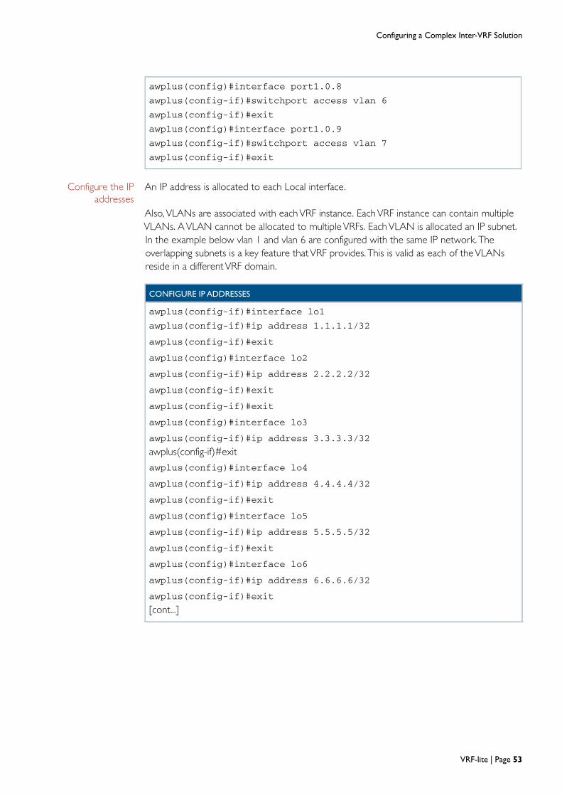
Configuring a Complex Inter-VRF Solution
CONFIGURE IP ADDRESSES
awplus(config-if)#exit
[cont...]
Configure the IP addresses
An IP address is allocated to each Local interface.
Also, VLANs are associated with eachVRF instance. EachVRF instance can contain multipleVLANs. AVLAN cannot be allocated to multipleVRFs. EachVLAN is allocated an IP subnet.In the example below vlan 1 and vlan 6 are configured with the same IP network. Theoverlapping subnets is a key feature thatVRF provides. This is valid as each of theVLANsreside in a differentVRF domain.
awplus(config)#interface port1.0.8
awplus(config-if)#switchport access vlan 6
awplus(config-if)#exit
awplus(config)#interface port1.0.9
awplus(config-if)#switchport access vlan 7
awplus(config-if)#exit
awplus(config-if)#interface lo1
awplus(config-if)#ip address 1.1.1.1/32
awplus(config-if)#exit
awplus(config)#interface lo2
awplus(config-if)#ip address 2.2.2.2/32
awplus(config-if)#exit
awplus(config-if)#exit
awplus(config)#interface lo3
awplus(config-if)#ip address 3.3.3.3/32
awplus(config)#interface lo4
awplus(config-if)#ip address 4.4.4.4/32
awplus(config-if)#exit
awplus(config)#interface lo5
awplus(config-if)#ip address 5.5.5.5/32
awplus(config-if)#exit
awplus(config)#interface lo6
awplus(config-if)#ip address 6.6.6.6/32
awplus(config-if)#exit
VRF-lite | Page 53

Configuring a Complex Inter-VRF Solution
awplus(config)#interface vlan1
awplus(config-if)#ip vrf forwarding red
awplus(config-if)#ip address 192.168.10.1/24
awplus(config)#interface vlan2
awplus(config-if)#ip vrf forwarding green
awplus(config-if)#ip address 192.168.20.1/24
awplus(config-if)#exit
awplus(config)#interface vlan3
awplus(config-if)#ip vrf forwarding blue
awplus(config-if)#ip address 192.168.30.1/24
awplus(config-if)#exit
awplus(config)#interface vlan4
awplus(config-if)#ip vrf forwarding orange
awplus(config-if)#ip address 192.168.40.1/24
awplus(config-if)#exit
[awplus(config)#interface vlan5
awplus(config-if)#ip vrf forwarding shared
awplus(config-if)#ip address 192.168.100.1/24
awplus(config-if)#exit
awplus(config)#interface vlan6
awplus(config-if)#ip vrf forwarding overlap
awplus(config-if)#ip address 192.168.10.1/24
awplus(config-if)#exit
awplus(config)#interface vlan7
awplus(config-if)#ip vrf forwarding overlap
awplus(config-if)#ip address 192.168.50.1/24
awplus(config-if)#exit
Page 54 | VRF-lite
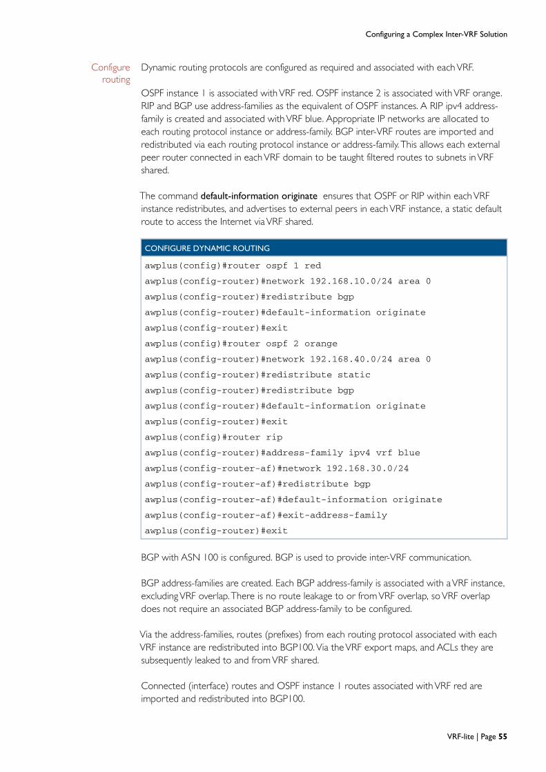
Configuring a Complex Inter-VRF Solution
CONFIGURE DYNAMIC ROUTING
Configure routing
Dynamic routing protocols are configured as required and associated with eachVRF.
OSPF instance 1 is associated withVRF red. OSPF instance 2 is associated withVRF orange.RIP and BGP use address-families as the equivalent of OSPF instances. A RIP ipv4 address-family is created and associated withVRF blue. Appropriate IP networks are allocated toeach routing protocol instance or address-family. BGP inter-VRF routes are imported andredistributed via each routing protocol instance or address-family. This allows each externalpeer router connected in eachVRF domain to be taught filtered routes to subnets inVRFshared.
The command default-information originate ensures that OSPF or RIP within eachVRFinstance redistributes, and advertises to external peers in eachVRF instance, a static defaultroute to access the Internet viaVRF shared.
BGP with ASN 100 is configured. BGP is used to provide inter-VRF communication.
BGP address-families are created. Each BGP address-family is associated with aVRF instance,excludingVRF overlap. There is no route leakage to or fromVRF overlap, soVRF overlapdoes not require an associated BGP address-family to be configured.
Via the address-families, routes (prefixes) from each routing protocol associated with eachVRF instance are redistributed into BGP100.Via theVRF export maps, and ACLs they aresubsequently leaked to and fromVRF shared.
Connected (interface) routes and OSPF instance 1 routes associated with VRF red areimported and redistributed into BGP100.
awplus(config)#router ospf 1 red
awplus(config-router)#network 192.168.10.0/24 area 0
awplus(config-router)#redistribute bgp
awplus(config-router)#default-information originate
awplus(config-router)#exit
awplus(config)#router ospf 2 orange
awplus(config-router)#network 192.168.40.0/24 area 0
awplus(config-router)#redistribute static
awplus(config-router)#redistribute bgp
awplus(config-router)#default-information originate
awplus(config-router)#exit
awplus(config)#router rip
awplus(config-router)#address-family ipv4 vrf blue
awplus(config-router-af)#network 192.168.30.0/24
awplus(config-router-af)#redistribute bgp
awplus(config-router-af)#default-information originate
awplus(config-router-af)#exit-address-family
awplus(config-router)#exit
VRF-lite | Page 55

Configuring a Complex Inter-VRF Solution
Connected routes associated withVRF green are redistributed into BGP, and also advertisedto the external BGP neighbor router. VRF green has an i-BGP peering relationship to itsneighbor as the neighbor ASN is the same (ASN 100). BGP routes learned from the externali-BGP neighbor are added to BGP 100. As the connection is i-BGP (not e-BGP), the BGPcommand next-hop-self is required to ensure the next-hop IP address is modified for eachprefix advertised to the external i-BGP peer. The next hop address becomes theVRF greenvlan2 ip address ‘192.168.20.1’. Without this command inter-VRF routes advertised to theexternal i-BGP peer would retain the original next-hop IP address associated withVRFshared.
For example, the i-BGP standard dictates that without the command next-hop-self, theVRFshared route 192.168.44.0/24 leaked intoVRF green would be advertised to the externalVRF green i-BGP peer retaining the originalVRF shared next-hop IP 192.168.100.2, instead ofbeing modified to become theVRF green vlan2 IP 192.168.20.1.
The e-BGP standard dictates that the next-hop IP is automatically modified when advertisinga prefix to an e-BGP neighbor, so the command next-hop-self is not required for external e-BGP peering relationships.
The default-originate command is required to ensure BGP redistributes theVRF green staticdefault route toVRF green external i-BGP neighbor.
Connected routes and RIPv2 routes associated withVRF blue are imported andredistributed into BGP to be leaked toVRF shared.
Connected routes, OSPF instance 2 routes, and the static route associated withVRF orangeare redistributed into BGP.VRF orange also has two static routes to orange router subnets192.168.140.0/24 and 192.168.20.0/24. Only static route 192.168.140.0/24 is redistributedinto BGP. Previously, VRF orange static route 192.168.20.0/24 was filtered viaVRF exportACL as the network address range is also used elsewhere - withVRF green vlan2.
Connected routes and static routes associated withVRF shared are redistributed into BGP.VRF shared has static routes to external shared router networks 192.168.43.0/24,192.168.44.0/24 and 192.168.45.0/24 as well as a static default route to the Internet. VRFshared has an e-BGP peering relationship to its Internet-facing neighbor as the neighbor ASNis different (peer ASN = 300 instead of 100).The external Internet router learns routes to allnetworks associated withVRFs red, green, blue and orange via the e-BGP peeringrelationship.
Note: A unique AS number (ASN) is allocated to each AS for use in BGP routing. Thenumbers are assigned by IANA and the Regional Internet Registries (RIR), the sameauthorities that allocate IP addresses. There are public numbers, which may be usedon the Internet and range from 1 to 64511, and private numbers from 64512 to65535, which can be used within an organization.
Page 56 | VRF-lite
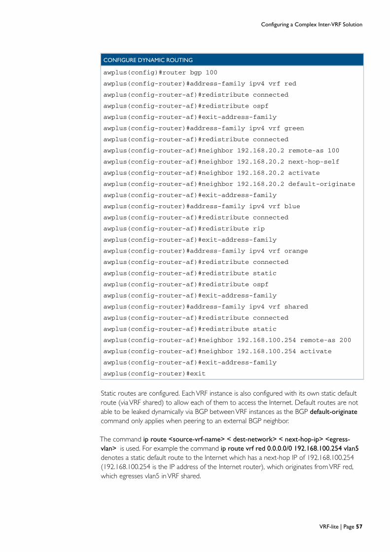
Configuring a Complex Inter-VRF Solution
Static routes are configured. EachVRF instance is also configured with its own static defaultroute (viaVRF shared) to allow each of them to access the Internet. Default routes are notable to be leaked dynamically via BGP betweenVRF instances as the BGP default-originate
command only applies when peering to an external BGP neighbor.
The command ip route <source-vrf-name> < dest-network> < next-hop-ip> <egress-
vlan> is used. For example the command ip route vrf red 0.0.0.0/0 192.168.100.254 vlan5
denotes a static default route to the Internet which has a next-hop IP of 192.168.100.254(192.168.100.254 is the IP address of the Internet router), which originates fromVRF red,which egresses vlan5 inVRF shared.
CONFIGURE DYNAMIC ROUTING
awplus(config)#router bgp 100
awplus(config-router)#address-family ipv4 vrf red
awplus(config-router-af)#redistribute connected
awplus(config-router-af)#redistribute ospf
awplus(config-router-af)#exit-address-family
awplus(config-router)#address-family ipv4 vrf green
awplus(config-router-af)#redistribute connected
awplus(config-router-af)#neighbor 192.168.20.2 remote-as 100
awplus(config-router-af)#neighbor 192.168.20.2 next-hop-self
awplus(config-router-af)#neighbor 192.168.20.2 activate
awplus(config-router-af)#neighbor 192.168.20.2 default-originate
awplus(config-router-af)#exit-address-family
awplus(config-router)#address-family ipv4 vrf blue
awplus(config-router-af)#redistribute connected
awplus(config-router-af)#redistribute rip
awplus(config-router-af)#exit-address-family
awplus(config-router)#address-family ipv4 vrf orange
awplus(config-router-af)#redistribute connected
awplus(config-router-af)#redistribute static
awplus(config-router-af)#redistribute ospf
awplus(config-router-af)#exit-address-family
awplus(config-router)#address-family ipv4 vrf shared
awplus(config-router-af)#redistribute connected
awplus(config-router-af)#redistribute static
awplus(config-router-af)#neighbor 192.168.100.254 remote-as 200
awplus(config-router-af)#neighbor 192.168.100.254 activate
awplus(config-router-af)#exit-address-family
awplus(config-router)#exit
VRF-lite | Page 57

Configuring a Complex Inter-VRF Solution
CONFIGURE STATIC ROUTING
CONFIGURE ROUTE MAPS
The routes configured onVRF shared do not need to specify the egressVLAN, as they arenot inter-VRF routes. So, the command ip route vrf shared 192.168.45.0/24 192.168.100.2
denotes a static route to destination network 192.168.45.0/24 which has a next hop of192.168.100.2, which originates fromVRF shared, which egressesVLAN5 inVRF shared. Inthis example eachVRF instance red, green, blue, orange and shared has their own staticdefault route to the Internet viaVRF shared.
Configure route maps
The final part of this configuration example is the route-map configuration. The commandroute-map routemap-name permit 1 is used to create a route-map. Each route-map in turnreferences a particular standard ACL.
VRF export maps filter routes exported to BGP.VRF import maps filter routes imported intotheVRF domain from BGP. BGP is used to leak routes betweenVRFs.
awplus(config)#ip route vrf red 0.0.0.0/0 192.168.100.254 vlan5
awplus(config)#ip route vrf green 0.0.0.0/0 192.168.100.254 vlan5
awplus(config)#ip route vrf blue 0.0.0.0/0 192.168.100.254 vlan5
awplus(config)#ip route vrf orange 0.0.0.0/0 192.168.100.254 vlan5
awplus(config)#ip route vrf orange 192.168.20.0/24 192.168.40.2
awplus(config)#ip route vrf orange 192.168.140.0/24 192.168.40.2
awplus(config)#ip route vrf shared 0.0.0.0/0 192.168.100.254
awplus(config)#ip route vrf shared 192.168.43.0/24 192.168.100.2
awplus(config)#ip route vrf shared 192.168.44.0/24 192.168.100.2
awplus(config)#ip route vrf shared 192.168.45.0/24 192.168.100.2
awplus(config)#route-map red43 permit 1
awplus(config-route-map)#match ip address redBlock4445
awplus(config-route-map)#exit
awplus(config)#route-map green44 permit 1
awplus(config-route-map)#match ip address greenBlock4345
awplus(config-route-map)#exit
awplus(config)#route-map blue45 permit 1
awplus(config-route-map)#match ip address blueBlock4344
awplus(config-route-map)#exit
awplus(config)#route-map orange434445 permit 1
awplus(config-route-map)#match ip address orangeNoBlock
awplus(config-route-map)#exit
awplus(config)#route-map orange140 permit 1
awplus(config-route-map)#match ip address orangeBlock20Export140
awplus(config-route-map)#exit
awplus(config)#exits
Page 58 | VRF-lite
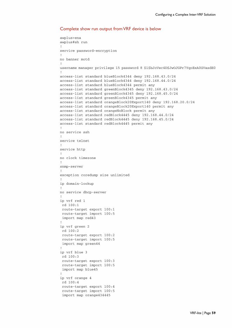
Configuring a Complex Inter-VRF Solution
Complete show run output from VRF device is below
awplus>enaawplus#sh run!service password-encryption!no banner motd!username manager privilege 15 password 8 $1$bJoVec4D$JwOJGPr7YqoExA0GVasdE0!access-list standard blueBlock4344 deny 192.168.43.0/24access-list standard blueBlock4344 deny 192.168.44.0/24access-list standard blueBlock4344 permit anyaccess-list standard greenBlock4345 deny 192.168.43.0/24access-list standard greenBlock4345 deny 192.168.45.0/24access-list standard greenBlock4345 permit anyaccess-list standard orangeBlock20Export140 deny 192.168.20.0/24access-list standard orangeBlock20Export140 permit anyaccess-list standard orangeNoBlock permit anyaccess-list standard redBlock4445 deny 192.168.44.0/24access-list standard redBlock4445 deny 192.168.45.0/24access-list standard redBlock4445 permit any!no service ssh!service telnet!service http!no clock timezone!snmp-server!exception coredump size unlimited!ip domain-lookup!no service dhcp-server!ip vrf red 1rd 100:1route-target export 100:1route-target import 100:5import map red43!ip vrf green 2rd 100:2route-target export 100:2route-target import 100:5import map green44!ip vrf blue 3rd 100:3route-target export 100:3route-target import 100:5import map blue45!ip vrf orange 4rd 100:4route-target export 100:4route-target import 100:5import map orange434445
VRF-lite | Page 59

Configuring a Complex Inter-VRF Solution
export map orange140!ip vrf shared 5rd 100:5route-target import 100:1route-target import 100:2route-target import 100:3route-target import 100:4route-target export 100:5!ip vrf overlap 6!no ip multicast-routing!spanning-tree mode rstp!access-list hardware access43permit ip any 192.168.43.0/24access-list hardware access44permit ip any 192.168.44.0/24access-list hardware access45permit ip any 192.168.45.0/24access-list hardware allow100_deny_privatepermit ip any 192.168.100.0/24deny ip any 192.168.0.0/16access-list hardware allow_to_self_10permit ip any 192.168.10.0/24access-list hardware allow_to_self_20permit ip any 192.168.20.0/24access-list hardware allow_to_self_30permit ip any 192.168.30.0/24access-list hardware allow_to_self_40permit ip any 192.168.40.0/24!switch 1 provision x900-24!vlan databasevlan 2-7 state enable!interface port1.0.1switchportswitchport mode accessaccess-group allow_to_self_10access-group access43access-group allow100_deny_private!interface port1.0.2switchportswitchport mode accessswitchport access vlan 2access-group allow_to_self_20access-group access44access-group allow100_deny_private!interface port1.0.3switchportswitchport mode accessswitchport access vlan 3access-group allow_to_self_30access-group access45access-group allow100_deny_private!interface port1.0.4-1.0.5switchport
Page 60 | VRF-lite

Configuring a Complex Inter-VRF Solution
switchport mode accessswitchport access vlan 4access-group allow_to_self_40access-group access43access-group access44access-group access45access-group allow100_deny_private!interface port1.0.6-1.0.7switchportswitchport mode accessswitchport access vlan 5!interface port1.0.8switchportswitchport mode accessswitchport access vlan 6!interface port1.0.9switchportswitchport mode accessswitchport access vlan 7!interface port1.0.10-1.0.24switchportswitchport mode access!interface lo1ip address 1.1.1.1/32!interface lo2ip address 2.2.2.2/32!interface lo3ip address 3.3.3.3/32!interface lo4ip address 4.4.4.4/32!interface lo5ip address 5.5.5.5/32!interface lo6ip address 6.6.6.6/32!interface vlan1ip vrf forwarding redip address 192.168.10.1/24!interface vlan2ip vrf forwarding greenip address 192.168.20.1/24!interface vlan3ip vrf forwarding blueip address 192.168.30.1/24!interface vlan4ip vrf forwarding orangeip address 192.168.40.1/24!interface vlan5ip vrf forwarding sharedip address 192.168.100.1/24
VRF-lite | Page 61

Configuring a Complex Inter-VRF Solution
!interface vlan6ip vrf forwarding overlapip address 192.168.10.1/24!interface vlan7ip vrf forwarding overlapip address 192.168.50.1/24!router ospf 1 rednetwork 192.168.10.0/24 area 0redistribute bgpdefault-information originate!router ospf 2 orangenetwork 192.168.40.0/24 area 0redistribute staticredistribute bgpdefault-information originate!router rip!address-family ipv4 vrf bluenetwork 192.168.30.0/24redistribute bgpdefault-information originateexit-address-family!router bgp 100!address-family ipv4 vrf redredistribute connectedredistribute ospfexit-address-family!address-family ipv4 vrf greenredistribute connectedneighbor 192.168.20.2 remote-as 100neighbor 192.168.20.2 next-hop-selfneighbor 192.168.20.2 activateneighbor 192.168.20.2 default-originateexit-address-family!address-family ipv4 vrf blueredistribute connectedredistribute ripexit-address-family!address-family ipv4 vrf orangeredistribute connectedredistribute staticredistribute ospfexit-address-family!address-family ipv4 vrf sharedredistribute connectedredistribute staticneighbor 192.168.100.254 remote-as 200neighbor 192.168.100.254 activateexit-address-family!ip route vrf red 0.0.0.0/0 192.168.100.254 vlan5ip route vrf green 0.0.0.0/0 192.168.100.254 vlan5ip route vrf blue 0.0.0.0/0 192.168.100.254 vlan5
Page 62 | VRF-lite

Configuring a Complex Inter-VRF Solution
ip route vrf orange 0.0.0.0/0 192.168.100.254 vlan5ip route vrf orange 192.168.20.0/24 192.168.40.2ip route vrf orange 192.168.140.0/24 192.168.40.2ip route vrf shared 0.0.0.0/0 192.168.100.254ip route vrf shared 192.168.43.0/24 192.168.100.2ip route vrf shared 192.168.44.0/24 192.168.100.2ip route vrf shared 192.168.45.0/24 192.168.100.2!route-map red43 permit 1match ip address redBlock4445!route-map green44 permit 1match ip address greenBlock4345!route-map blue45 permit 1match ip address blueBlock4344!route-map orange434445 permit 1match ip address orangeNoBlock!route-map orange140 permit 1match ip address orangeBlock20Export140!!line con 0line vty 0 4!end
IP route table from VRF device is below
awplus#show ip routeNo entries in route table
[VRF: red]Codes: C - connected, S - static, R - RIP, B - BGP
O - OSPF, IA - OSPF inter areaN1 - OSPF NSSA external type 1, N2 - OSPF NSSA external type 2E1 - OSPF external type 1, E2 - OSPF external type 2* - candidate default
Gateway of last resort is 192.168.100.254 to network 0.0.0.0
S* 0.0.0.0/0 [1/0] via 192.168.100.254, vlan5C 1.1.1.1/32 is directly connected, lo1B 5.5.5.5/32 [20/0] is directly connected, lo5, 00:07:21C 192.168.10.0/24 is directly connected, vlan1O 192.168.13.0/24 [110/2] via 192.168.10.2, vlan1, 00:06:27O 192.168.14.0/24 [110/2] via 192.168.10.2, vlan1, 00:06:27B 192.168.43.0/24 [20/0] via 192.168.100.2, vlan5, 00:07:17B 192.168.100.0/24 [20/0] is directly connected, vlan5, 00:07:17
[VRF: green]S* 0.0.0.0/0 [1/0] via 192.168.100.254, vlan5C 2.2.2.2/32 is directly connected, lo2B 5.5.5.5/32 [20/0] is directly connected, lo5, 00:07:21B 192.168.15.0/24 [200/0] via 192.168.20.2, vlan2, 00:06:15B 192.168.16.0/24 [200/0] via 192.168.20.2, vlan2, 00:06:14C 192.168.20.0/24 is directly connected, vlan2B 192.168.44.0/24 [20/0] via 192.168.100.2, vlan5, 00:07:17B 192.168.100.0/24 [20/0] is directly connected, vlan5, 00:07:17
VRF-lite | Page 63

Configuring a Complex Inter-VRF Solution
[VRF: blue]S* 0.0.0.0/0 [1/0] via 192.168.100.254, vlan5C 3.3.3.3/32 is directly connected, lo3B 5.5.5.5/32 [20/0] is directly connected, lo5, 00:07:21R 192.168.17.0/24 [120/2] via 192.168.30.2, vlan3, 00:06:48R 192.168.18.0/24 [120/2] via 192.168.30.2, vlan3, 00:06:48C 192.168.30.0/24 is directly connected, vlan3B 192.168.45.0/24 [20/0] via 192.168.100.2, vlan5, 00:07:17B 192.168.100.0/24 [20/0] is directly connected, vlan5, 00:07:17
[VRF: orange]S* 0.0.0.0/0 [1/0] via 192.168.100.254, vlan5C 4.4.4.4/32 is directly connected, lo4B 5.5.5.5/32 [20/0] is directly connected, lo5, 00:07:20O E2 192.168.19.0/24 [110/20] via 192.168.40.3, vlan4, 00:06:29S 192.168.20.0/24 [1/0] via 192.168.40.2, vlan4C 192.168.40.0/24 is directly connected, vlan4B 192.168.43.0/24 [20/0] via 192.168.100.2, vlan5, 00:07:17B 192.168.44.0/24 [20/0] via 192.168.100.2, vlan5, 00:07:17B 192.168.45.0/24 [20/0] via 192.168.100.2, vlan5, 00:07:16B 192.168.100.0/24 [20/0] is directly connected, vlan5, 00:07:17S 192.168.140.0/24 [1/0] via 192.168.40.2, vlan4
[VRF: shared]S* 0.0.0.0/0 [1/0] via 192.168.100.254, vlan5B 1.1.1.1/32 [20/0] is directly connected, lo1, 00:07:21B 2.2.2.2/32 [20/0] is directly connected, lo2, 00:07:21B 3.3.3.3/32 [20/0] is directly connected, lo3, 00:07:21B 4.4.4.4/32 [20/0] is directly connected, lo4, 00:07:21C 5.5.5.5/32 is directly connected, lo5B 192.168.10.0/24 [20/0] is directly connected, vlan1, 00:07:17B 192.168.13.0/24 [20/2] via 192.168.10.2, vlan1, 00:06:26B 192.168.14.0/24 [20/2] via 192.168.10.2, vlan1, 00:06:26B 192.168.15.0/24 [200/0] via 192.168.20.2, vlan2, 00:06:15B 192.168.16.0/24 [200/0] via 192.168.20.2, vlan2, 00:06:15B 192.168.17.0/24 [20/2] via 192.168.30.2, vlan3, 00:06:47B 192.168.18.0/24 [20/2] via 192.168.30.2, vlan3, 00:06:47B 192.168.19.0/24 [20/20] via 192.168.40.3, vlan4, 00:06:28B 192.168.20.0/24 [20/0] is directly connected, vlan2, 00:07:17B 192.168.30.0/24 [20/0] is directly connected, vlan3, 00:07:17B 192.168.40.0/24 [20/0] is directly connected, vlan4, 00:07:17S 192.168.43.0/24 [1/0] via 192.168.100.2, vlan5S 192.168.44.0/24 [1/0] via 192.168.100.2, vlan5S 192.168.45.0/24 [1/0] via 192.168.100.2, vlan5C 192.168.100.0/24 is directly connected, vlan5B 192.168.140.0/24 [20/0] via 192.168.40.2, vlan4, 00:07:15
[VRF: overlap]C 6.6.6.6/32 is directly connected, lo6C 192.168.10.0/24 is directly connected, vlan6C 192.168.50.0/24 is directly connected, vlan7awplus#
Page 64 | VRF-lite

Configuring a Complex Inter-VRF Solution
Configuration files for each external router used in the topology and its associated route table is below. None of the external routers are VRF aware.
hostname Internet_router!vlan databasevlan 2 state enable!interface port1.0.2switchport access vlan 2!interface vlan1ip address 192.168.100.254/24!interface vlan2ip address 192.168.200.1/24!router bgp 200bgp router-id 192.168.200.1neighbor 192.168.100.1 remote-as 100neighbor 192.168.100.1 activate!ip route 0.0.0.0/0 192.168.200.254!
Internet_router#show ip routeCodes: C - connected, S - static, R - RIP, B - BGP
O - OSPF, IA - OSPF inter areaN1 - OSPF NSSA external type 1, N2 - OSPF NSSA external type 2E1 - OSPF external type 1, E2 - OSPF external type 2* - candidate default
Gateway of last resort is 192.168.200.254 to network 0.0.0.0
S* 0.0.0.0/0 [1/0] via 192.168.200.254, vlan2B 1.1.1.1/32 [20/0] via 192.168.100.1, vlan1, 00:09:30B 2.2.2.2/32 [20/0] via 192.168.100.1, vlan1, 00:09:30B 3.3.3.3/32 [20/0] via 192.168.100.1, vlan1, 00:09:30B 4.4.4.4/32 [20/0] via 192.168.100.1, vlan1, 00:09:30B 5.5.5.5/32 [20/0] via 192.168.100.1, vlan1, 00:09:30B 192.168.10.0/24 [20/0] via 192.168.100.1, vlan1, 00:09:30B 192.168.13.0/24 [20/0] via 192.168.100.1, vlan1, 00:09:30B 192.168.14.0/24 [20/0] via 192.168.100.1, vlan1, 00:09:30B 192.168.15.0/24 [20/0] via 192.168.100.1, vlan1, 00:09:30B 192.168.16.0/24 [20/0] via 192.168.100.1, vlan1, 00:09:30B 192.168.17.0/24 [20/0] via 192.168.100.1, vlan1, 00:09:30B 192.168.18.0/24 [20/0] via 192.168.100.1, vlan1, 00:09:30B 192.168.19.0/24 [20/0] via 192.168.100.1, vlan1, 00:09:30B 192.168.20.0/24 [20/0] via 192.168.100.1, vlan1, 00:09:30B 192.168.30.0/24 [20/0] via 192.168.100.1, vlan1, 00:09:30B 192.168.40.0/24 [20/0] via 192.168.100.1, vlan1, 00:09:30B 192.168.43.0/24 [20/0] via 192.168.100.2, vlan1, 00:09:30B 192.168.44.0/24 [20/0] via 192.168.100.2, vlan1, 00:09:30B 192.168.45.0/24 [20/0] via 192.168.100.2, vlan1, 00:09:30C 192.168.100.0/24 is directly connected, vlan1B 192.168.140.0/24 [20/0] via 192.168.100.1, vlan1, 00:09:30C 192.168.200.0/24 is directly connected, vlan2Internet_router#
VRF-lite | Page 65

Configuring a Complex Inter-VRF Solution
hostname shared_router!vlan databasevlan 2-4 state enable!interface port1.0.2switchport access vlan 2!interface port1.0.3switchport access vlan 3!interface port1.0.4switchport access vlan 4!interface vlan1ip address 192.168.100.2/24!interface vlan2ip address 192.168.43.1/24!interface vlan3ip address 192.168.44.1/24!interface vlan4ip address 192.168.45.1/24!ip route 0.0.0.0/0 192.168.100.1!
shared_router#show ip routeCodes: C - connected, S - static, R - RIP, B - BGP
O - OSPF, IA - OSPF inter areaN1 - OSPF NSSA external type 1, N2 - OSPF NSSA external type 2E1 - OSPF external type 1, E2 - OSPF external type 2* - candidate default
Gateway of last resort is 192.168.100.1 to network 0.0.0.0
S* 0.0.0.0/0 [1/0] via 192.168.100.1, vlan1C 192.168.43.0/24 is directly connected, vlan2C 192.168.44.0/24 is directly connected, vlan3C 192.168.45.0/24 is directly connected, vlan4C 192.168.100.0/24 is directly connected, vlan1shared_router#
Page 66 | VRF-lite

Configuring a Complex Inter-VRF Solution
hostname red_ospf_peer!vlan databasevlan 2-3 state enable!interface port1.0.2switchport access vlan 2!interface port1.0.3switchport access vlan 3!interface vlan1ip address 192.168.10.2/24!interface vlan2ip address 192.168.13.1/24!interface vlan3ip address 192.168.14.1/24!router ospf 1ospf router-id 192.168.10.2network 192.168.10.0/24 area 0redistribute connected!
red_ospf_peer#show ip routeCodes: C - connected, S - static, R - RIP, B - BGP
O - OSPF, IA - OSPF inter areaN1 - OSPF NSSA external type 1, N2 - OSPF NSSA external type 2E1 - OSPF external type 1, E2 - OSPF external type 2* - candidate default
Gateway of last resort is 192.168.10.1 to network 0.0.0.0
O*E2 0.0.0.0/0 [110/10] via 192.168.10.1, vlan1, 00:00:07O E2 5.5.5.5/32 [110/1] via 192.168.10.1, vlan1, 00:00:07C 192.168.10.0/24 is directly connected, vlan1C 192.168.13.0/24 is directly connected, vlan2C 192.168.14.0/24 is directly connected, vlan3O E2 192.168.43.0/24 [110/1] via 192.168.10.1, vlan1, 00:00:07O E2 192.168.100.0/24 [110/1] via 192.168.10.1, vlan1, 00:00:07red_ospf_peer#
VRF-lite | Page 67

Configuring a Complex Inter-VRF Solution
hostname green_i_BGP_peer!vlan databasevlan 2-3 state enable!interface port1.0.2switchport access vlan 2!interface port1.0.3switchport access vlan 3!interface vlan1ip address 192.168.20.2/24!interface vlan2ip address 192.168.15.1/24!interface vlan3ip address 192.168.16.1/24!router bgp 100bgp router-id 192.168.20.2redistribute connectedneighbor 192.168.20.1 remote-as 100neighbor 192.168.20.1 activate!
green_i_bgp_peer#show ip routeCodes: C - connected, S - static, R - RIP, B - BGP
O - OSPF, IA - OSPF inter areaN1 - OSPF NSSA external type 1, N2 - OSPF NSSA external type 2E1 - OSPF external type 1, E2 - OSPF external type 2* - candidate default
Gateway of last resort is 192.168.20.1 to network 0.0.0.0
B* 0.0.0.0/0 [200/0] via 192.168.20.1, vlan1, 00:02:58B 2.2.2.2/32 [200/0] via 192.168.20.1, vlan1, 00:02:58B 5.5.5.5/32 [200/0] via 192.168.20.1, vlan1, 00:02:58C 192.168.15.0/24 is directly connected, vlan2C 192.168.16.0/24 is directly connected, vlan3C 192.168.20.0/24 is directly connected, vlan1B 192.168.44.0/24 [200/0] via 192.168.20.1, vlan1, 00:02:58B 192.168.100.0/24 [200/0] via 192.168.20.1, vlan1, 00:02:58green_i_BGP_peer#
Page 68 | VRF-lite

Configuring a Complex Inter-VRF Solution
hostname blue_rip_peer!vlan databasevlan 2-3 state enable!interface port1.0.2switchport access vlan 2!interface port1.0.3switchport access vlan 3!interface vlan1ip address 192.168.30.2/24!interface vlan2ip address 192.168.17.1/24!interface vlan3ip address 192.168.18.1/24!router ripnetwork 192.168.30.0/24redistribute connected!
blue_rip_peer#show ip routeCodes: C - connected, S - static, R - RIP, B - BGP
O - OSPF, IA - OSPF inter areaN1 - OSPF NSSA external type 1, N2 - OSPF NSSA external type 2E1 - OSPF external type 1, E2 - OSPF external type 2* - candidate default
Gateway of last resort is 192.168.30.1 to network 0.0.0.0
R* 0.0.0.0/0 [120/2] via 192.168.30.1, vlan1, 00:00:02R 5.5.5.5/32 [120/2] via 192.168.30.1, vlan1, 00:00:02C 192.168.17.0/24 is directly connected, vlan2C 192.168.18.0/24 is directly connected, vlan3C 192.168.30.0/24 is directly connected, vlan1R 192.168.45.0/24 [120/2] via 192.168.30.1, vlan1, 00:00:02R 192.168.100.0/24 [120/2] via 192.168.30.1, vlan1, 00:00:02blue_rip_peer#
VRF-lite | Page 69
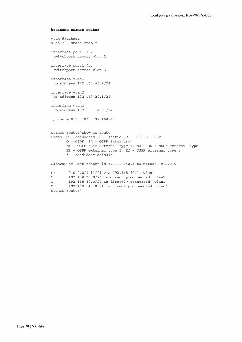
Configuring a Complex Inter-VRF Solution
hostname orange_router!vlan databasevlan 2-3 state enable!interface port1.0.2switchport access vlan 2!interface port1.0.3switchport access vlan 3!interface vlan1ip address 192.168.40.2/24!interface vlan2ip address 192.168.20.1/24!interface vlan3ip address 192.168.140.1/24!ip route 0.0.0.0/0 192.168.40.1!
orange_router#show ip routeCodes: C - connected, S - static, R - RIP, B - BGP
O - OSPF, IA - OSPF inter areaN1 - OSPF NSSA external type 1, N2 - OSPF NSSA external type 2E1 - OSPF external type 1, E2 - OSPF external type 2* - candidate default
Gateway of last resort is 192.168.40.1 to network 0.0.0.0
S* 0.0.0.0/0 [1/0] via 192.168.40.1, vlan1C 192.168.20.0/24 is directly connected, vlan2C 192.168.40.0/24 is directly connected, vlan1C 192.168.140.0/24 is directly connected, vlan3orange_router#
Page 70 | VRF-lite

Configuring a Complex Inter-VRF Solution
hostname orange_ospf_peer!vlan databasevlan 2 state enable!interface port1.0.2switchport access vlan 2!interface vlan1ip address 192.168.40.3/24!interface vlan2ip address 192.168.19.1/24!router ospf 1ospf router-id 192.168.40.3network 192.168.40.0/24 area 0redistribute connected!orange_ospf_peer# show ip routeCodes: C - connected, S - static, R - RIP, B - BGP
O - OSPF, IA - OSPF inter areaN1 - OSPF NSSA external type 1, N2 - OSPF NSSA external type 2E1 - OSPF external type 1, E2 - OSPF external type 2* - candidate default
Gateway of last resort is 192.168.40.1 to network 0.0.0.0
O*E2 0.0.0.0/0 [110/10] via 192.168.40.1, vlan1, 00:05:34O E2 5.5.5.5/32 [110/1] via 192.168.40.1, vlan1, 00:05:34C 192.168.19.0/24 is directly connected, vlan2O E2 192.168.20.0/24 [110/20] via 192.168.40.2, vlan1, 00:05:34C 192.168.40.0/24 is directly connected, vlan1O E2 192.168.43.0/24 [110/1] via 192.168.40.1, vlan1, 00:05:34O E2 192.168.44.0/24 [110/1] via 192.168.40.1, vlan1, 00:05:34O E2 192.168.45.0/24 [110/1] via 192.168.40.1, vlan1, 00:05:34O E2 192.168.100.0/24 [110/1] via 192.168.40.1, vlan1, 00:05:34O E2 192.168.140.0/24 [110/20] via 192.168.40.2, vlan1, 00:05:34orange_ospf_peer#
VRF-lite | Page 71

VCStack and VRF-lite
VCStack and VRF-lite
x900
x610 DUTAstack member 1
Port1.0.11VLAN 11 grey
e-BGP peering VRF greyfrom x900 lo8 80.80.80.2 to DUTA lo8 8.8.8.1via VLAN 15
Port2.0.10VLAN 10 violet
Port2.0.15
VLAN 15 grey
Port1.0.14
VLAN 14 violet
Port1.0.14
VLAN 14 violet
Port1.0.15
VLAN 15 grey
Port1.0.1Port1.0.1
Port2.0.1
Port1.0.2
stack member 2
VLAN 14
violet
VLAN 15
grey
e-BGP peering VRF violetfrom x900 lo7 70.70.70.2 to DUTA lo7 7.7.7.1 via VLAN 14
The following example illustrates how to configureVRF-lite in aVCStacked environment.
In the example below, each port from the x900 connects to a different x610VCStackmember. Each port also belongs to a differentVRF domain.
E-BGP peering between IP local addresses is used between the x900 and x610VCStackmembers on a perVRF basis - in order for the x900 device to learn routes to x610 subnetsassociated with eachVRF.
Other features used in this configuration
In the configuration below, you will notice a couple of features in use that have not beenpreviously discussed, namely stack provisioning and virtual-chassis ID.
Stack provisioning
Provisioning provides the ability to pre-configure a switch for stacking.
With provisioning, you can configure stack members and their ports, even though they arenot currently physically present, and configure them ready for future addition to the stack.This means that you can either pre-configure ports belonging to a switch that has not yetbeen installed, or load a configuration that references these ports.
For example:
switch 1 provision x610-48
switch 2 provision x610-48
Note: You can only stack, and therefore provision, switches of the same basic model.
Page 72 | VRF-lite

VCStack and VRF-lite
Virtual Chassis ID
Also, the optional command stack virtual-chassis-id <value> specifies theVCS virtual chassisID.
If not configured, the stack will automatically select a virtual-chassis-id from a number withinthe assigned range 0-4095. The ID selected will determine which virtual MAC address thestack will automatically use. The MAC address assigned to a stack must be unique within itsnetwork.
For more information aboutVCStack, refer to http://www.alliedtelesis.com/media/fount/how_to_note_alliedware_plus/overview_aw_plus__stacking_REVD.pdf.
X610 VCStack configuration!hostname DUTA!stack virtual-chassis-id 2034!ip vrf violet 7rd 100:7!ip vrf grey 8rd 100:8!switch 1 provision x610-48switch 2 provision x610-48!vlan databasevlan 10-11,14-15 state enable!interface port1.0.1switchport access vlan 14!interface port1.0.11switchport access vlan 11!interface port1.0.14switchport access vlan 14!interface port2.0.1switchport access vlan 15!interface port2.0.10switchport access vlan 10!interface port2.0.15switchport access vlan 15!interface lo7ip address 7.7.7.1/32!interface lo8ip address 8.8.8.1/32!interface vlan10ip vrf forwarding violetip address 10.10.10.1/24!interface vlan11ip vrf forwarding grey
VRF-lite | Page 73
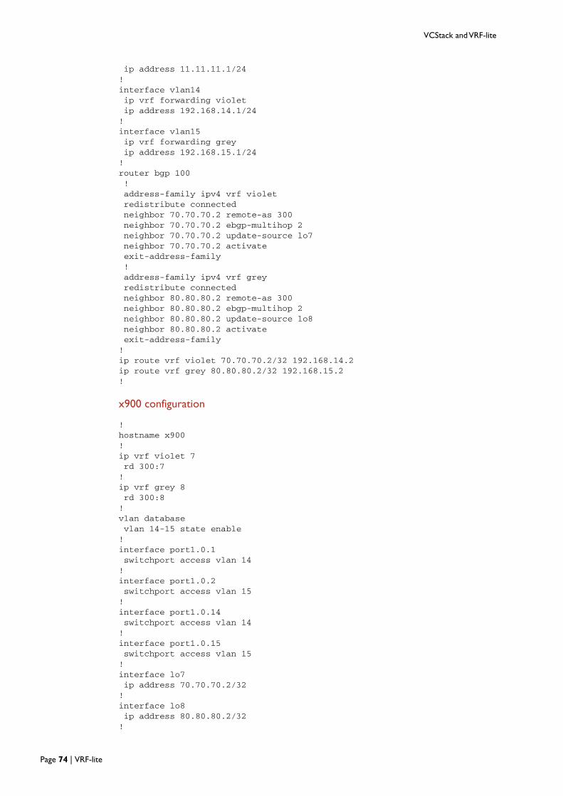
VCStack and VRF-lite
ip address 11.11.11.1/24!interface vlan14ip vrf forwarding violetip address 192.168.14.1/24!interface vlan15ip vrf forwarding greyip address 192.168.15.1/24!router bgp 100!address-family ipv4 vrf violetredistribute connectedneighbor 70.70.70.2 remote-as 300neighbor 70.70.70.2 ebgp-multihop 2neighbor 70.70.70.2 update-source lo7neighbor 70.70.70.2 activateexit-address-family!address-family ipv4 vrf greyredistribute connectedneighbor 80.80.80.2 remote-as 300neighbor 80.80.80.2 ebgp-multihop 2neighbor 80.80.80.2 update-source lo8neighbor 80.80.80.2 activateexit-address-family!ip route vrf violet 70.70.70.2/32 192.168.14.2ip route vrf grey 80.80.80.2/32 192.168.15.2!
x900 configuration
!hostname x900!ip vrf violet 7rd 300:7!ip vrf grey 8rd 300:8!vlan databasevlan 14-15 state enable!interface port1.0.1switchport access vlan 14!interface port1.0.2switchport access vlan 15!interface port1.0.14switchport access vlan 14!interface port1.0.15switchport access vlan 15!interface lo7ip address 70.70.70.2/32!interface lo8ip address 80.80.80.2/32!
Page 74 | VRF-lite

VCStack and VRF-lite
interface vlan14ip vrf forwarding violetip address 192.168.14.2/24!interface vlan15ip vrf forwarding greyip address 192.168.15.2/24!router bgp 300!address-family ipv4 vrf greynetwork 80.80.80.2/32redistribute connectedneighbor 8.8.8.1 remote-as 100neighbor 8.8.8.1 ebgp-multihop 2neighbor 8.8.8.1 update-source lo8neighbor 8.8.8.1 activateexit-address-family!address-family ipv4 vrf violetnetwork 70.70.70.2/32redistribute connectedneighbor 7.7.7.1 remote-as 100neighbor 7.7.7.1 ebgp-multihop 2neighbor 7.7.7.1 update-source lo7neighbor 7.7.7.1 activateexit-address-family!ip route vrf violet 7.7.7.1/32 192.168.14.1ip route vrf grey 8.8.8.1/32 192.168.15.1!
VRF-lite | Page 75
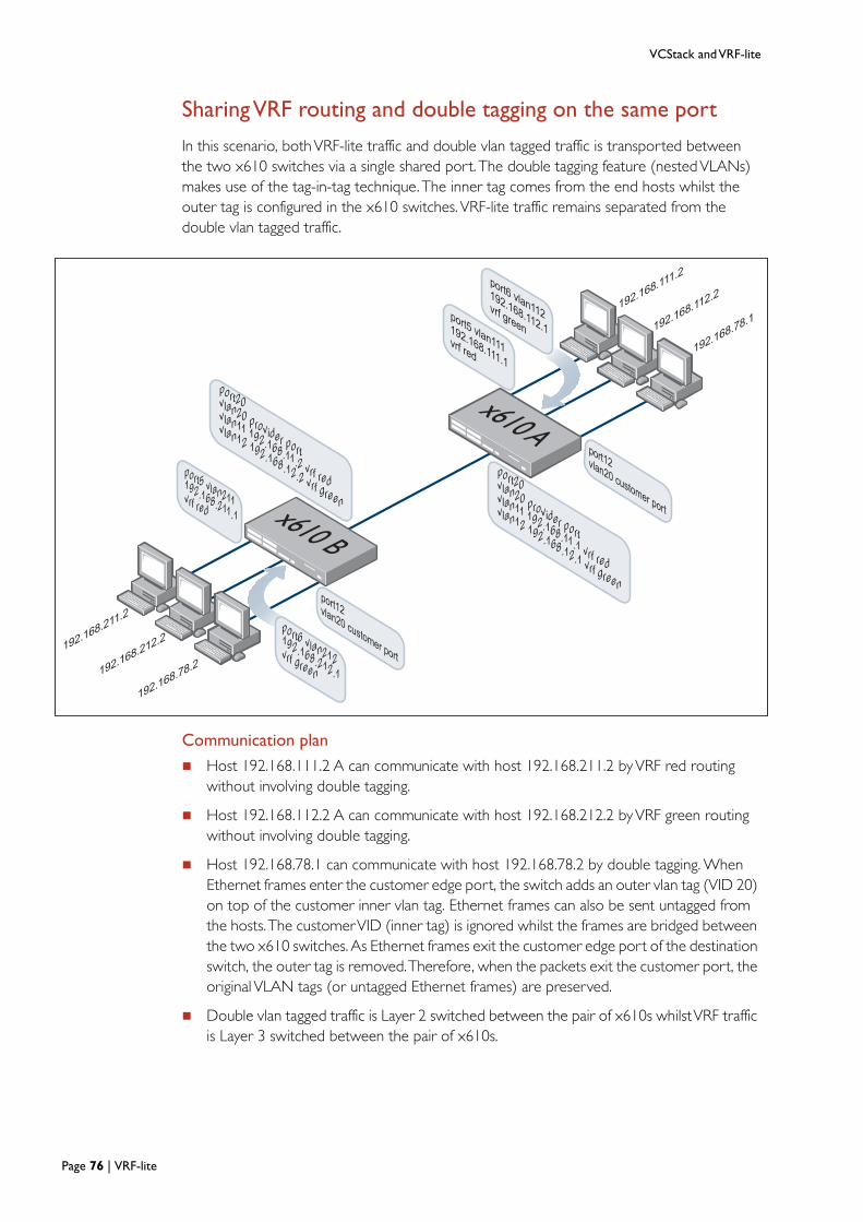
VCStack and VRF-lite
x610 A
192.168.78.2
x610 B
192.168.78.1
192.168.212.2192.168.211.2
192.168.111.2
192.168.112.2
port20vlan20 provider port
vlan11 192.168.11.1 vrf red
vlan12 192.168.12.1 vrf green
port5 vlan211192.168.211.1vrf red
port5 vlan111192.168.111.1vrf red
port12vlan20 customer port
port12vlan20 customer port
port6 vlan112192.168.112.1
vrf green
port6 vlan212192.168.212.1
vrf green
port20vlan20 provider port
vlan11 192.168.11.2 vrf red
vlan12 192.168.12.2 vrf green
Sharing VRF routing and double tagging on the same port
In this scenario, bothVRF-lite traffic and double vlan tagged traffic is transported betweenthe two x610 switches via a single shared port. The double tagging feature (nestedVLANs)makes use of the tag-in-tag technique. The inner tag comes from the end hosts whilst theouter tag is configured in the x610 switches. VRF-lite traffic remains separated from thedouble vlan tagged traffic.
Communication plan
Host 192.168.111.2 A can communicate with host 192.168.211.2 byVRF red routingwithout involving double tagging.
Host 192.168.112.2 A can communicate with host 192.168.212.2 byVRF green routingwithout involving double tagging.
Host 192.168.78.1 can communicate with host 192.168.78.2 by double tagging. WhenEthernet frames enter the customer edge port, the switch adds an outer vlan tag (VID 20)on top of the customer inner vlan tag. Ethernet frames can also be sent untagged fromthe hosts.The customerVID (inner tag) is ignored whilst the frames are bridged betweenthe two x610 switches. As Ethernet frames exit the customer edge port of the destinationswitch, the outer tag is removed.Therefore, when the packets exit the customer port, theoriginal VLAN tags (or untagged Ethernet frames) are preserved.
Double vlan tagged traffic is Layer 2 switched between the pair of x610s whilstVRF trafficis Layer 3 switched between the pair of x610s.
Page 76 | VRF-lite

VCStack and VRF-lite
Configurations
x610 Aip vrf red 1ip vrf green 2
vlan databasevlan 20 name nestedvlan 11-12,20,111-112 state enable
interface port1.0.5switchport access vlan 111
interface port1.0.6switchport access vlan 112
interface port1.0.12switchport access vlan 20switchport vlan-stacking customer-edge-port
interface port1.0.20switchport mode trunkswitchport trunk allowed vlan add 11-12,20switchport trunk native vlan noneswitchport vlan-stacking provider-port
interface vlan11ip vrf forwarding redip address 192.168.11.1/24
interface vlan12ip vrf forwarding greenip address 192.168.12.1/24
interface vlan111ip vrf forwarding redip address 192.168.111.1/24
interface vlan112ip vrf forwarding greenip address 192.168.112.1/24
ip route vrf red 192.168.211.0/24 192.168.11.2ip route vrf green 192.168.212.0/24 192.168.12.2
x610 Bip vrf red 1ip vrf green 2
vlan databasevlan 20 name nestedvlan 11-12,20,111-112 state enable
interface port1.0.5switchport access vlan 111
interface port1.0.6switchport access vlan 112
interface port1.0.12switchport access vlan 20switchport vlan-stacking customer-edge-port
VRF-lite | Page 77
VCStack and VRF-lite
interface port1.0.20switchport mode trunkswitchport trunk allowed vlan add 11-12,20switchport trunk native vlan noneswitchport vlan-stacking provider-port
interface vlan11ip vrf forwarding redip address 192.168.11.2/24
interface vlan12ip vrf forwarding greenip address 192.168.12.2/24
interface vlan111ip vrf forwarding redip address 192.168.211.1/24
interface vlan112ip vrf forwarding greenip address 192.168.212.1/24
ip route vrf red 192.168.111.0/24 192.168.11.1ip route vrf green 192.168.112.0/24 192.168.12.1
Page 78 | VRF-lite
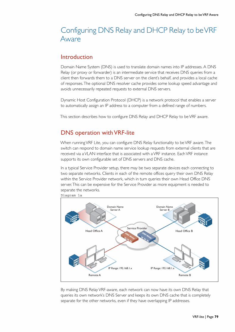
Configuring DNS Relay and DHCP Relay to be VRF Aware
Configuring DNS Relay and DHCP Relay to be VRF Aware
Introduction
Domain Name System (DNS) is used to translate domain names into IP addresses. A DNSRelay (or proxy or forwarder) is an intermediate service that receives DNS queries from aclient then forwards them to a DNS server on the client’s behalf, and provides a local cacheof responses. The optional DNS resolver cache provides some lookup speed advantage andavoids unnecessarily repeated requests to external DNS servers.
Dynamic Host Configuration Protocol (DHCP) is a network protocol that enables a serverto automatically assign an IP address to a computer from a defined range of numbers.
This section describes how to configure DNS Relay and DHCP Relay to beVRF aware.
DNS operation with VRF-lite
When running VRF Lite, you can configure DNS Relay functionality to be VRF aware. The
switch can respond to domain name service lookup requests from external clients that are
received via a VLAN interface that is associated with a VRF instance. Each VRF instance
supports its own configurable set of DNS servers and DNS cache.
In a typical Service Provider setup, there may be two separate devices each connecting to
two separate networks. Clients in each of the remote offices query their own DNS Relay
within the Service Provider network, which in turn queries their own Head Office DNS
server. This can be expensive for the Service Provider as more equipment is needed to
separate the networks.
DNS Relay
DNS Relay
Head Office A Head Office B
Remote A Remote B
Domain Name Server A
Domain Name Server B
IP Range: 192.168.1.x IP Range: 192.168.1.x
Service Provider
Diagram 1a
By making DNS RelayVRF-aware, each network can now have its own DNS Relay thatqueries its own network’s DNS Server and keeps its own DNS cache that is completelyseparate for the other networks, even if they have overlapping IP addresses.
VRF-lite | Page 79

Configuring DNS Relay and DHCP Relay to be VRF Aware
Configuring DNS operation with VRF-lite
The command ip name-server [vrf <name>] <ip-address>, configures a name-server for thespecifiedVRF. This command assigns the address of one or more name-servers to aVRFtable to be used for name and address resolution. If noVRF-lite instance (vrf <name>) isspecified, the name-server is configured for the global VRF. A name-server that is configuredon the globalVRF will apply to both the DNS relay and DNS client.
Note that the DNS client is notVRF aware. VRF aware client services that can utilize the DNS client such as ping, traceroute, telnet, and ssh will only perform DNS lookup if the URLis not specified in the command. For example, the command ping VRF <instance>
<address> is supported, but pingVRF <instance> <URL> is not supported.
AVRF specific name-cache is created within the DNS relay for everyVRF instance that has aname-server configured.
A maximum of three name-servers may be defined for each DNS-relay instance.
The configuration command, ip dns forwarding applies the DNS forwarding cache to allVRFinstances configured on the device and not on a perVRF basis.
The configuration commands listed below apply to allVRF instances configured on the deviceand not on a perVRF basis. Timeouts are in seconds as per existing commands:
ip dns forwarding retry
ip dns forwarding timeout
ip dns forwarding dead-time
ip dns forwarding source-interface
ip dns forwarding cache
The following show commands provide output information for theVRF instance specified. IfaVRF instance is not specified, output is shown for all VRF instances including the globalinstance and the output will be formatted in a way that distinguishes the information for eachVRF.
show ip dns [vrf <name>|global]forwarding server
show ip dns [vrf <name>|global] forwarding cache
show ip name-server [vrf <name>|global]
The DNS cache can also be cleared on a perVRF instance basis by using the clear ip dns [vrf<name>|global] forwarding cache command.
The following commands show how to configure a DNS relay name-server for both thespecifiedVRF instanceVRF red, and the global VRF instance.
Page 80 | VRF-lite

Configuring DNS Relay and DHCP Relay to be VRF Aware
To configure a DNS relay name-server for theVRF-lite instance red:
awplus# configure terminal
awplus(config)# ip name-server vrf red 192.168.0.1
awplus# ip domain-lookup
To configure a DNS relay name-server for the global VRF instance:
awplus# configure terminal
awplus(config)# ip name-server 192.168.1.1
awplus# ip domain-lookup
DHCP operation with VRF-lite
You can configure DHCP relay to forward packets within aVRF-lite instance.
DHCP messages between DHCP clients and a DHCP server are then able to be relayedbetweenVLAN interfaces within aVRF instance.
When an DHCP relay instance is enabled on aVLAN interface using the command ip dhcp-
relay <server>, the relay will be placed within the sameVRF instance that theVLAN belongsto. If theVLAN does not belong to aVRF instance, then the DHCP relay will be placed in thedefault (global)VRF.
Note that DHCP option 82 is still supported on a DHCP relay operating within aVRFinstance.
The following commands can be used to monitor DHCP relay functions:
show counter dhcp-relay [vrf<vrf-name>|global]
show ip dhcp-relay [vrf <name>|global] [interface<ifname>]
The following example shows how to configure DHCP relay for aVLAN interface that isassociated with namedVRF instanceVRF red:
awplus# configure terminal
awplus(config)# interface vlan1
awplus (config if)# ip vrf red
awplus (config if)#ip address 192.168.0.1/24
awplus (config if)#ip dhcp-relay server-address 192.168.1.1
VRF-lite | Page 81

Configuring DNS Relay and DHCP Relay to be VRF Aware
Combined DNS Relay DHCP Relay solution
A single pair of x610 switches is used to service multiple separate customer networks. Eachcustomer network is contained within aVRF instance to provide separation.VRF aware DNSRelay and DHCP Relay services are configured in the x610 switches.
One global and threeVRF instancesVRF#1VRF#2 andVRF#3 is configured.
The Global instance consists of the following:
Global
Hosts network 192.168.10.X/24 is configured with a DNS Server and a DHCP Serverlocated atVLAN200 192.168.1.1/24
Each of theVRF instances has following configuration:
VRF#1
Hosts network192.168.10.X/24 is configured with a DNS Server and a DHCP Serverlocated atVLAN10 192.168.1.1/24
VRF#2
Hosts network192.168.20.X/24 is configured with a DNS Server and a DHCP Serverlocated atVLAN20 192.168.2.1/24
VRF#3
Hosts network192.168.30.X/24 is configured with a DNS Server and a DHCP Serverlocated atVLAN30 192.168.3.1/24
DNS ServerDHCP Server
DNS ServerDHCP Server
DNS ServerDHCP Server
DNS ServerDHCP Server
VLAN 10, VRF#1192.168.1.0/24
VLAN 200, GLOBAL192.168.1.0/24
VLAN 30, VRF#3192.168.3.0/24
VLAN 20, VRF#2192.168.2.0/24
x610Core (VRF)
x610Dist (VRF)
VLAN 1, VRF#1192.168.10.0/24
VLAN 2, VRF#2192.168.20.0/24
VLAN 3, VRF#3192.168.30.0/24
VLAN 300, GLOBAL192.168.10.0/24
VLAN 100, Global : 172.16.1.0/24VLAN 11 VRF#1 : 172.16.1.0/24VLAN 12 VRF#2 : 172.16.2.0/24VLAN 13 VRF#3 : 172.16.3.0/24
Page 82 | VRF-lite
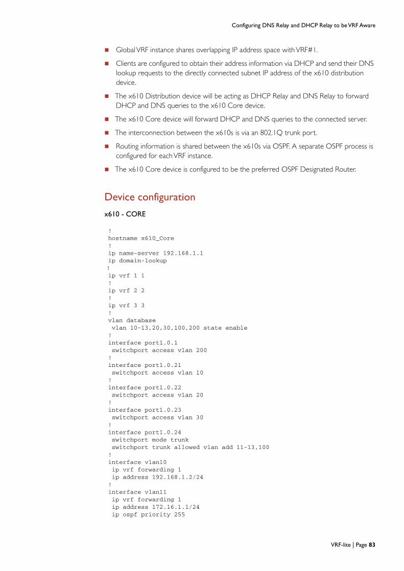
Configuring DNS Relay and DHCP Relay to be VRF Aware
GlobalVRF instance shares overlapping IP address space withVRF#1.
Clients are configured to obtain their address information via DHCP and send their DNSlookup requests to the directly connected subnet IP address of the x610 distributiondevice.
The x610 Distribution device will be acting as DHCP Relay and DNS Relay to forwardDHCP and DNS queries to the x610 Core device.
The x610 Core device will forward DHCP and DNS queries to the connected server.
The interconnection between the x610s is via an 802.1Q trunk port.
Routing information is shared between the x610s via OSPF. A separate OSPF process isconfigured for eachVRF instance.
The x610 Core device is configured to be the preferred OSPF Designated Router.
Device configuration
x610 - CORE
!hostname x610_Core!ip name-server 192.168.1.1ip domain-lookup!ip vrf 1 1!ip vrf 2 2!ip vrf 3 3!vlan databasevlan 10-13,20,30,100,200 state enable!interface port1.0.1switchport access vlan 200!interface port1.0.21switchport access vlan 10!interface port1.0.22switchport access vlan 20!interface port1.0.23switchport access vlan 30!interface port1.0.24switchport mode trunkswitchport trunk allowed vlan add 11-13,100!interface vlan10ip vrf forwarding 1ip address 192.168.1.2/24!interface vlan11ip vrf forwarding 1ip address 172.16.1.1/24ip ospf priority 255
VRF-lite | Page 83
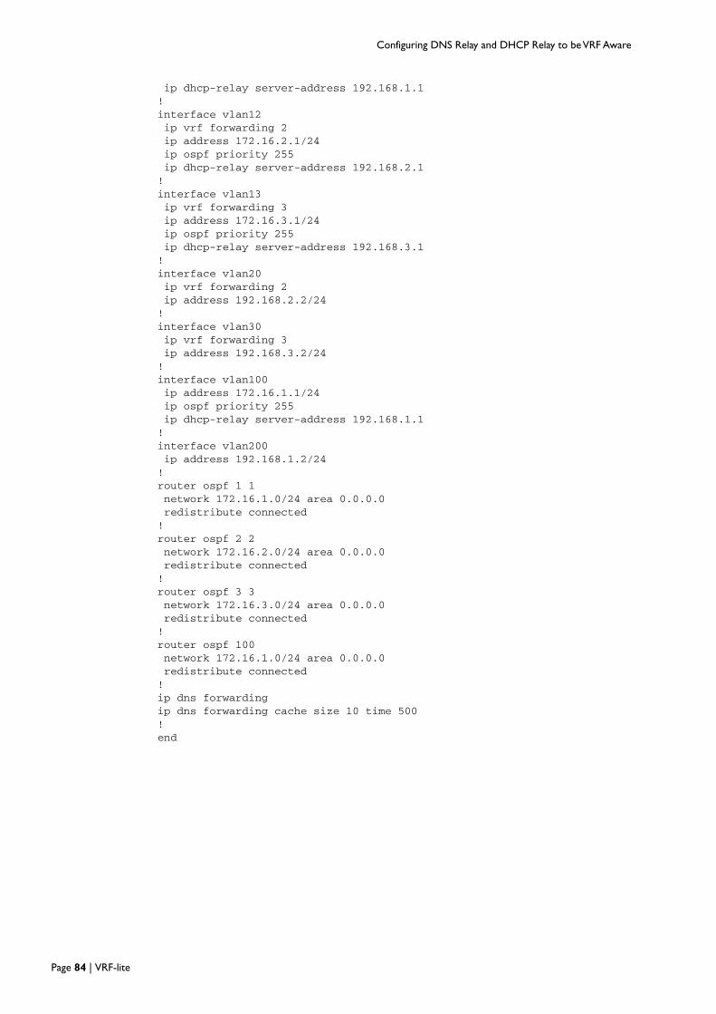
Configuring DNS Relay and DHCP Relay to be VRF Aware
ip dhcp-relay server-address 192.168.1.1!interface vlan12ip vrf forwarding 2ip address 172.16.2.1/24ip ospf priority 255ip dhcp-relay server-address 192.168.2.1!interface vlan13ip vrf forwarding 3ip address 172.16.3.1/24ip ospf priority 255ip dhcp-relay server-address 192.168.3.1!interface vlan20ip vrf forwarding 2ip address 192.168.2.2/24!interface vlan30ip vrf forwarding 3ip address 192.168.3.2/24!interface vlan100ip address 172.16.1.1/24ip ospf priority 255ip dhcp-relay server-address 192.168.1.1!interface vlan200ip address 192.168.1.2/24!router ospf 1 1network 172.16.1.0/24 area 0.0.0.0redistribute connected!router ospf 2 2network 172.16.2.0/24 area 0.0.0.0redistribute connected!router ospf 3 3network 172.16.3.0/24 area 0.0.0.0redistribute connected!router ospf 100network 172.16.1.0/24 area 0.0.0.0redistribute connected!ip dns forwardingip dns forwarding cache size 10 time 500!end
Page 84 | VRF-lite

Configuring DNS Relay and DHCP Relay to be VRF Aware
x610 - Distribution
!hostname x610_Distribution!ip name-server vrf 1 192.168.1.1ip name-server vrf 2 192.168.2.1ip name-server vrf 3 192.168.3.1ip name-server 192.168.1.1ip domain-lookup!ip vrf 1 1!ip vrf 2 2!ip vrf 3 3!vlan databasevlan 2-3,11-13,100,300 state enable!interface port1.0.1switchport access vlan 300
!interface port1.0.21switchport access vlan 1!interface port1.0.22switchport access vlan 2!interface port1.0.23switchport access vlan 3!interface port1.0.24switchport mode trunkswitchport trunk allowed vlan add 11-13,100!interface vlan1ip address 192.168.10.2/24ip dhcp-relay server-address 172.16.1.1!interface vlan2ip vrf forwarding 2ip address 192.168.20.2/24ip dhcp-relay server-address 172.16.2.1!interface vlan3ip vrf forwarding 3ip address 192.168.30.2/24ip dhcp-relay server-address 172.16.3.1!interface vlan11ip vrf forwarding 1ip address 172.16.1.2/24!interface vlan12ip vrf forwarding 2ip address 172.16.2.2/24!interface vlan13ip vrf forwarding 3ip address 172.16.3.2/24!interface vlan100
VRF-lite | Page 85

Configuring DNS Relay and DHCP Relay to be VRF Aware
ip address 172.16.1.2/24!interface vlan300ip address 192.168.10.2/24ip dhcp-relay server-address 172.16.1.1!router ospf 1 1network 172.16.1.0/24 area 0.0.0.0redistribute connected!router ospf 2 2network 172.16.2.0/24 area 0.0.0.0redistribute connected!router ospf 3 3network 172.16.3.0/24 area 0.0.0.0redistribute connected!router ospf 100network 172.16.1.0/24 area 0.0.0.0redistribute connected!ip dns forwardingip dns forwarding cache size 1000 timeout 3600!end
Page 86 | VRF-lite
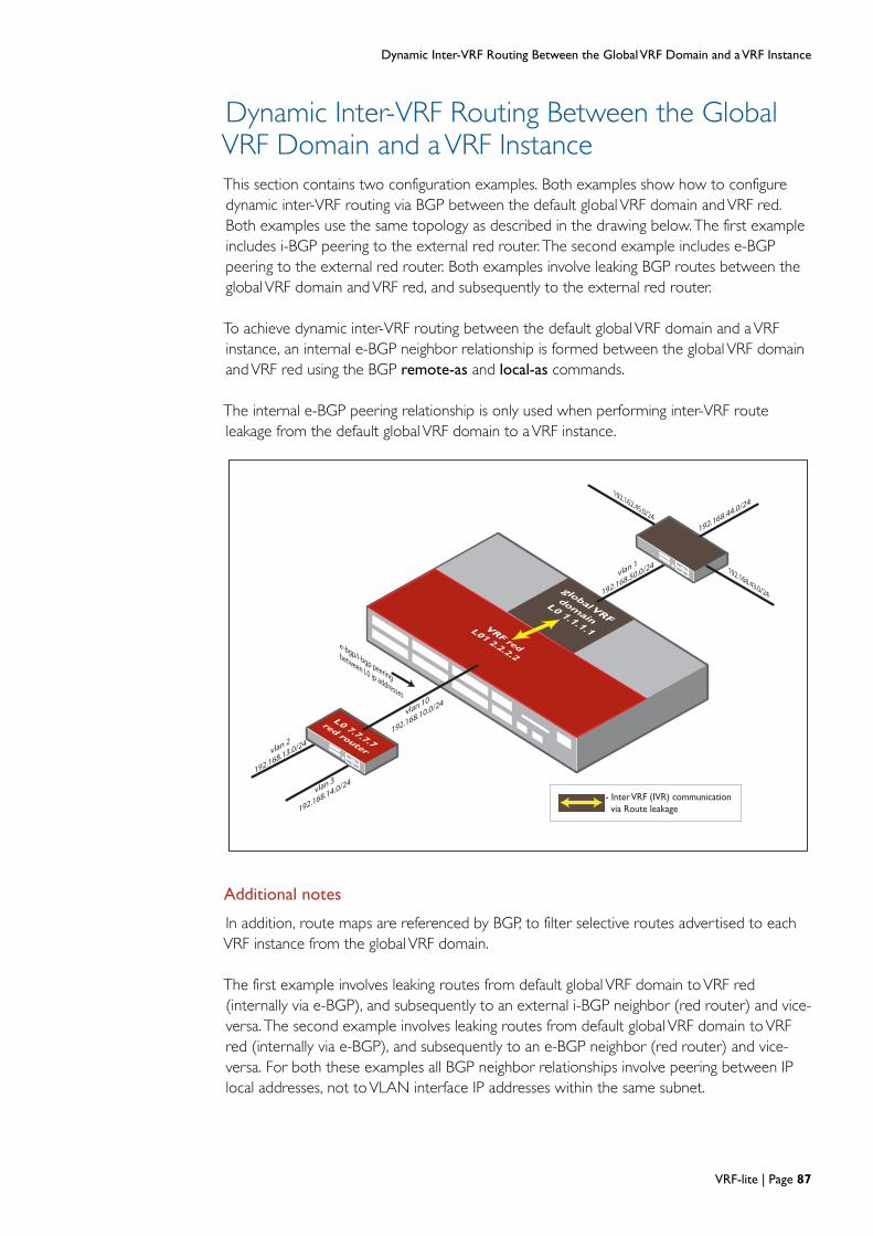
Dynamic Inter-VRF Routing Between the Global VRF Domain and a VRF Instance
Dynamic Inter-VRF Routing Between the Global VRF Domain and a VRF Instance
global VRF
domain
L0 1.1.1.1
L0 7.7.7.7
red router
e-bgp/i-bgp peering
between L0 ip addresses
192.162.45.0/24
192.168.43.0/24
vlan 10
192.168.10.0/24
vlan 1
192.168.50.0/24
192.168.44.0/24
vlan 3
192.168.14.0/24
vlan 2
192.168.13.0/24
- Inter VRF (IVR) communication
via Route leakage
VRF red
L01 2.2.2.2
This section contains two configuration examples. Both examples show how to configuredynamic inter-VRF routing via BGP between the default global VRF domain andVRF red.Both examples use the same topology as described in the drawing below.The first exampleincludes i-BGP peering to the external red router. The second example includes e-BGPpeering to the external red router. Both examples involve leaking BGP routes between theglobal VRF domain andVRF red, and subsequently to the external red router.
To achieve dynamic inter-VRF routing between the default global VRF domain and aVRFinstance, an internal e-BGP neighbor relationship is formed between the global VRF domainandVRF red using the BGP remote-as and local-as commands.
The internal e-BGP peering relationship is only used when performing inter-VRF routeleakage from the default global VRF domain to aVRF instance.
Additional notes
In addition, route maps are referenced by BGP, to filter selective routes advertised to eachVRF instance from the global VRF domain.
The first example involves leaking routes from default global VRF domain toVRF red(internally via e-BGP), and subsequently to an external i-BGP neighbor (red router) and vice-versa. The second example involves leaking routes from default global VRF domain toVRFred (internally via e-BGP), and subsequently to an e-BGP neighbor (red router) and vice-versa. For both these examples all BGP neighbor relationships involve peering between IPlocal addresses, not toVLAN interface IP addresses within the same subnet.
VRF-lite | Page 87
Dynamic Inter-VRF Routing Between the Global VRF Domain and a VRF Instance
BGP configuration tips
The following BGP configuration tips are included to explain the use of some BGP specificcommands used in the i-BGP and e-BGP example configuration files below.
neighbor x.x.x.x update-source lo
The command neighbor x.x.x.x update-source lo is used to ensure the lo is used as theupdate source when establishing the BGP neighbor relationship instead of the egressVLANinterface IP.
neighbor x.x.x.x ebgp-multihop 2
The command neighbor x.x.x.x ebgp-multihop 2 is not applicable for an i-BGP connection,but is required for e-BGP when peering to an IP address in a remote network. For example,when forming an e-BGP neighbor relationship to the IP local address configured in a remotepeer, the command is required.
This command above, is automatically generated when using e-BGP peering in conjunctionwith the neighbor x.x.x.x update-source command.The command defaults to hop count of2 when automatically generated, but it can be explicitly configured to allow e-BGP peering todevices up to 255 hops away.
I-BGP doesn't default to peers being in the same subnet, as it supports multi-hop
automatically. This is because the default configuration of i-BGP is a full mesh of all the
routers in the AS and there’s no expectation that all i-BGP peers within the mesh will be in
the same subnet. So, unlike e-BGP it can be quite common for an i-BGP TCP connection to
be formed to IP address in a remote network, instead of peering to an IP address in same
subnet.
In the case of e-BGP, it is uncommon to peer to a local loopback address, and similarly, theconnection is not typically via a multi-hop Layer 3 routed path - and the concept of a fullmesh between all peers doesn’t apply. Hence e-BGP defaults to not allowing peering beyonda single hop.
neighbor x.x.x.x next-hop-selfI-BGP does not change the next hop address contained in BGP routes. To get i-BGP tochange the nexthop IP, you need to use the neighbor x.x.x.x next-hop-self command.
neighbor x.x.x.x route-map <xx> out
The command neighbor x.x.x.x route-map <xx> out is used to reference and apply a routemap.The route map in turn references an access-list. The out parameter in the commandneighbor x.x.x.x route-map <xx> out specifies that the access list (used to filter routes),applies to outgoing advertisements.
The global parameter in the command neighbor x.x.x.x remote-as <64515> global isrequired to facilitate an e-BGP peering to the global VRF domain fromVRF red.
Conversely, the target vrf-name in the command neighbor x.x.x.x remote-as <64512> vrf
<red> is required to be configured to facilitate an e-BGP peering toVRF red from the globalVRF domain.
Page 88 | VRF-lite

Dynamic Inter-VRF Routing Between the Global VRF Domain and a VRF Instance
Additionally, the globalVRF domain contains remote-as 64512, and local-as 64515 to ensuree-BGP is used for internal peering toVRF red.
Conversely, VRF red contains remote-as 64515, and local-as 64512 to ensure e-BGP is usedfor internal peering to the global VRF domain.
VRF-lite | Page 89

Dynamic Inter-VRF Routing Between the Global VRF Domain and a VRF Instance
Dynamic inter-VRF communication with i-BGP routing to external peer
VRF device
access-list standard redblock4445 deny 192.168.44.0/24access-list standard redblock4445 deny 192.168.45.0/24access-list standard redblock4445 permit any!ip vrf red 1rd 100:1!vlan databasevlan 10 state enable!interface port1.0.3switchport access vlan 10!interface loip address 1.1.1.1/32!interface lo1ip address 2.2.2.2/32!interface vlan1ip address 192.168.50.1/24!interface vlan10ip vrf forwarding redip address 192.168.10.1/24!router bgp 100redistribute connectedredistribute staticneighbor 2.2.2.2 remote-as 64512 vrf redneighbor 2.2.2.2 local-as 64515neighbor 2.2.2.2 update-source 1.1.1.1neighbor 2.2.2.2 route-map 43 out!address-family ipv4 vrf redredistribute connectedredistribute staticneighbor 1.1.1.1 remote-as 64515 globalneighbor 1.1.1.1 local-as 64512neighbor 1.1.1.1 update-source lo1neighbor 1.1.1.1 activateneighbor 7.7.7.7 remote-as 100neighbor 7.7.7.7 update-source lo1neighbor 7.7.7.7 activateneighbor 7.7.7.7 next-hop-selfexit-address-family!ip route 2.2.2.2/32 lo1ip route 192.168.43.0/24 192.168.50.2ip route 192.168.44.0/24 192.168.50.2ip route 192.168.45.0/24 192.168.50.2ip route vrf red 1.1.1.1/32 loip route vrf red 7.7.7.7/32 192.168.10.2!route-map 43 permit 1match ip address redblock4445
Page 90 | VRF-lite

Dynamic Inter-VRF Routing Between the Global VRF Domain and a VRF Instance
red routervlan databasevlan 2-3 state enable!interface port1.0.13switchport access vlan 2!interface port1.0.14switchport access vlan 3!interface loip address 7.7.7.7/32!interface vlan1ip address 192.168.10.2/24!interface vlan2ip address 192.168.13.1/24!interface vlan3ip address 192.168.14.1/24!router bgp 100redistribute connectedredistribute staticneighbor 2.2.2.2 remote-as 100neighbor 2.2.2.2 update-source lo!ip route 2.2.2.2/32 192.168.10.1ip route 172.16.50.0/24 192.168.13.2ip route 172.16.55.0/24 192.168.14.2!
Dynamic inter-VRF communication with e-BGP routing to external peeraccess-list standard redblock4445 deny 192.168.44.0/24access-list standard redblock4445 deny 192.168.45.0/24access-list standard redblock4445 permit any!ip vrf red 1rd 100:1!vlan databasevlan 10 state enable!interface port1.0.3switchport access vlan 10!interface loip address 1.1.1.1/32!interface lo1ip address 2.2.2.2/32!interface vlan1ip address 192.168.50.1/24!interface vlan10ip vrf forwarding redip address 192.168.10.1/24!router bgp 100
VRF-lite | Page 91
Dynamic Inter-VRF Routing Between the Global VRF Domain and a VRF Instance
redistribute connectedredistribute staticneighbor 2.2.2.2 remote-as 64512 vrf redneighbor 2.2.2.2 local-as 64515neighbor 2.2.2.2 update-source 1.1.1.1neighbor 2.2.2.2 route-map 43 out!address-family ipv4 vrf redredistribute connectedredistribute staticneighbor 1.1.1.1 remote-as 64515 globalneighbor 1.1.1.1 local-as 64512neighbor 1.1.1.1 update-source lo1neighbor 1.1.1.1 activateneighbor 7.7.7.7 remote-as 300neighbor 7.7.7.7 ebgp-multihop 2neighbor 7.7.7.7 update-source lo1neighbor 7.7.7.7 activateexit-address-family!ip route 2.2.2.2/32 lo1ip route 192.168.43.0/24 192.168.50.2ip route 192.168.44.0/24 192.168.50.2ip route 192.168.45.0/24 192.168.50.2ip route vrf red 1.1.1.1/32 loip route vrf red 7.7.7.7/32 192.168.10.2!route-map 43 permit 1match ip address redblock4445
red router!vlan databasevlan 2-3 state enable!interface port1.0.13switchport access vlan 2!interface port1.0.14switchport access vlan 3!interface loip address 7.7.7.7/32!interface vlan1ip address 192.168.10.2/24!interface vlan2ip address 192.168.13.1/24!interface vlan3ip address 192.168.14.1/24!router bgp 300redistribute connectedredistribute staticneighbor 2.2.2.2 remote-as 100neighbor 2.2.2.2 ebgp-multihop 255neighbor 2.2.2.2 update-source lo!ip route 2.2.2.2/32 192.168.10.1ip route 172.16.50.0/24 192.168.13.2ip route 172.16.55.0/24 192.168.14.2!
Page 92 | VRF-lite

Route Limits
Route Limits
In multi-VRF network environment, it may be disastrous if oneVRF injects too many routesand fills up the hardware forwarding table (FIB) on a device which can affect otherVRFs (aswell as the global VRF).
In software version 5.4.2 and later, it is possible to mitigate this risk, as route limits can nowbe configured on a perVRF basis.
Existing AlliedWare Plus commands max-static-routes and max-fib-routes have beenextended in 5.4.2 to allow configurable static and dynamic route limits on a perVRF instancebasis.
Note: The command max-fib-routes only counts dynamic routes (not including static andconnected routes).
Note: By default, there is no preset allocation of the number of route table entries availableto eachVRF instance. When static and/or dynamicVRF instances are configured(without setting limits via the commands max-static-routes and max-fib-routes), thenumber of route table entries available to eachVRF instance are not automaticallyreserved.
Configuring static route limits
AlliedWare Plus supports the ability to limit static routes via the max-static-routes commandin the global VRF domain, with a default maximum limit of 1000 (routes). This sameAlliedWare Plus command is now also able to be applied on a perVRF basis.
Static route limits can be applied as part ofVRF Configuration Mode via the command:
awplus(vrf-config)# max-static-routes <1-1000>
The following example shows how to configure a limit of 200 static routes, applied toVRFred:
awplus(config)# ip vrf red
awplus(config-vrf)# max-static-routes 200
Note: Static routes limits are applied before adding routes to the RIB. Rejected static routeswill not be in the running config.
VRF-lite | Page 93

Route Limits
Configuring dynamic route limits
AlliedWare Plus supports the ability to limit dynamic routes via the max-fib-routes
command in the globalVRF domain, which is unlimited by default. This same AlliedWare Pluscommand is now also able to be applied on a perVRF basis.
max-fib-routes
Description Use the command max-fib-routes to set the maximum number of dynamic routes in FIB(Forwarding Information Base). Static and Connected routes are not included. Dynamicroutes to be added to the HW FIB table that exceed the configured limit are rejected.
When an additional threshold value (in percentage) is configured, a warning message isgenerated if the number of dynamic routes in the FIB exceeds the threshold, and the routesexceeding the limit are rejected.If warning-only is specified, routes are still allowed to beadded, but a warning message is generated when the threshold is reached.
When this command is executed inVRF Configuration mode, it sets the maximum numberof dynamic routes that can be added to the HW FIB table associated with theVRF instance.
Command Syntax
max-fib-routes <1-4294967294> (<1-100>|warning-only|)
Default By default, the maximum number of dynamic routes is 4294967294 and no warningthreshold is set.
Command Level
Warning thresholds (percentage) can be configured for dynamic route limits.
awplus(vrf-config)# max-fib-routes <1-4294967294> WARNING-THRESHOLD%
Examples To set the maximum number of dynamic routes to 2000 and warning threshold with 75%,applied toVRF red HW FIB, configure the following:
awplus(config)# ip vrf red
awplus(config-vrf)# max-fib-routes 2000 75
PARAMETER DESCRIPTION
max-fib-routes Set maximum fib routes number
<1- 4294967294> Allowed number of fib routes excluding Connect and Static
<1-100> Warning threshold in percentage
warning-only Allow to add more routes than the limit but with warning message
PROMPT MODE PRIVILEGE LEVEL
(config) CONFIG_MODE PRIVILEGE_MAX
(config-vrf) VRF_MODE PRIVILEGE_VR_MAX
Page 94 | VRF-lite
Route Limits
PARAMETER DESCRIPTION
no Negate a command or set its defaults
max-fib-routes Set maximum fib routes number
PROMPT MODE PRIVILEGE LEVEL
(config) CONFIG_MODEPRIVILEGE_MAX
PRIVILEGE_MAX
(config-vrf) VRF_MODEPRIVILEGE_VR_MAX
PRIVILEGE_VR_MAX
Alternatively, to ensure a warning message is generated when the number of routes exceedsthe limit (whilst ensuring routes exceeding the limit can still be added), configure thefollowing:
awplus(config)# ip vrf red
awplus(vrf-config)# max-fib-routes <1-4294967294> warning-only
Note: Dynamic limits routes are applied before adding routes to the FIB. All routes, includingrejected dynamic routes can be displayed via the command show ip route database.
See Also max-fib-routes
no max-fib-routes
show ip route
no max-fib-routes
Description Use this command to reset the maximum number of dynamic routes in FIB.
When this command is executed inVRF Configuration mode, it sets the maximum numberof dynamic routes that can be added to the HW FIB table associated with theVRF instance.
Command Syntax
no max-fib-routes
Default By default, the maximum number of dynamic routes is 4294967294 and no warningthreshold is set.
Command Level
See Also max-fib-routes
show ip route
VRF-lite | Page 95

Utilities Available within VRF-lite
Utilities Available withinVRF-liteA number of network utility and management features are now supported within aVFR-liteenvironment. These include:
Ping
Trace Route
Telnet Client
SSH Client
TCP Dump
Note that unless specifically configured with either static or leaked routes, these commandswill not operate across routing domains. This is shown in the following examples:
Example 1 In the example diagram shown below, use the following command to ping the IP address192.168.30.15 from the global routing domain, to a destination that resides within the samedomain:
awplus# ping 192.168.30.15
Example 2 In the example diagram shown below, use the following command to ping from withinVRFgreen to destination 192.168.20.10 that resides within the same routing domain:
awplus# ping vrf green 192.168.20.10
Figure 1: Using the Ping command with VRF-lite
Note: Running the ping command acrossVRF instances, or from the Global Routing Domainto a target located within aVRF instance, will not work unless either static or leakedroutes exist on both the source and target devices.
Global Routing Domain
Global Routing Domain
externalrouter
greenrouter
externalrouter
192.168.30.15 192.168.20.10
192.168.20.2192.168.30.1
VRF Green
VRF_routing_ping-example.eps
Page 96 | VRF-lite

Utilities Unavailable within VRF-lite
Utilities Unavailable withinVRF-liteIn thisVRF-lite implementation, the following applications and Layer 4+ services are notsupported on a per-VRF basis.
Telnet Server
SSH Server
File Copy
System Log
SNMP Server
DHCP Server
NTP Server
Although not supported withinVRF instances, these services are supported in the globalVRF domain context, which is equivalent to a non-VRF environment.
VRF-lite | Page 97

VRF-lite Usage Guidelines
VRF-lite Usage Guidelines
VRF-LITE SPECIFIC GUIDELINES
Utility services such asTFTP, SNMP, SSH server, telnet server, system log, file copy, DHCPserver, DHCP snooping, NTP server are notVRF aware and remain available in the globalVRF domain only.
VRF-lite is supported for IPv4 unicast and broadcast traffic only. Layer 2 and Layer 3 multicastservices, including IGMP snooping, IGMP querier, IGMP proxy, PIM remain available via theglobal VRF domain only.
IPv6 routing protocols are notVRF aware and remain available in the globalVRF domainonly.
SNMP and syslog services remain available via the global VRF domain only.
In the case of NestedVLANs (VLAN double tagging), all VLANs (and associated switchports) must be a member of the global VRF domain only.
GVRP is not supported in conjunction withVRF-lite.
QoS services remain available via the global VRF domain only.
Subnet-basedVLAN classification is not supported in conjunction withVRF-lite.
All privateVLANs must be a member of the global VRF domain only.
802.1Q trunked links are able to span multipleVRF instances with the x610 product only.802.1Q trunked links are not able to span multipleVRF instances with x900 series switchand the Switchblade x908 switch - all VLANs associated with an 802.1Q trunked link mustexist within a singleVRF instance for these products.
All dataVLANs and associated control VLAN associated with an EPSR domain must existwithin the sameVRF instance. For example, EPSR dataVLAN(s) cannot reside in a differentVRF instance than the associated control VLAN for an EPSR domain.
Both RSTP or MSTP can be used in conjunction withVRF.VLANs associated with an MSTPinstance should exist within sameVRF instance.
802.1x authentication services remain available via the global VRF domain only.
VRRP instances continue to operate on a per port basis - VRRP monitored interfacesdefined in aVRRP instance should exist within the sameVRF instance as theVRRP instance.
Filtering services (routemaps, access groups, ACLs) continue to work independently ofVRF-lite.
Static aggregation and LACP continue to work independently ofVRF-lite.
LLDP continues to work independently ofVRF-lite.
The general guideline is that all current services remain available in the default global VRFdomain only, unless the service is either explicitlyVRF aware, or the service runs completelyindependently ofVRF and therefore has no requirement to beVRF aware.
Page 98 | VRF-lite
Useful VRF-Related Diagnostics Command List
Useful VRF-Related Diagnostics Command List
Below is a summary list of diagnostics commands that you may find helpful whentroubleshootingVRF-related issues. Many existing commands have been madeVRF awareand some are included below. Please refer to the software reference manual for a completelist ofVRF aware commands.
Generalawplus#show tech-supportawplus#show running-configawplus#show running-config vrfawplus#show systemawplus#show bootawplus#show clockawplus#show license
VRFawplus#show ip vrfawplus#show ip vrf ?WORD VRF instance namebrief Brief VRF instance informationdetail Detailed VRF instance informationinterface Interface information| Output modifiers> Output redirection>> Output redirection (append)<cr>
awplus#show ip vrf interfaceawplus#show ip vrf detail
Routing generalawplus#show ip route(selected routes listed for each VRF)Codes: C - connected, S - static, R - RIP, B - BGP
O - OSPF, IA - OSPF inter areaN1 - OSPF NSSA external type 1, N2 - OSPF NSSA external type 2E1 - OSPF external type 1, E2 - OSPF external type 2* - candidate default
[VRF: <VRFname A>][VRF: <VRFnameB>][VRF: <VRFnameC>]
awplus#show ip route database
(complete route table database listed for each VRF)
Codes: C - connected, S - static, R - RIP, B - BGPO - OSPF, IA - OSPF inter areaN1 - OSPF NSSA external type 1, N2 - OSPF NSSA external type 2E1 - OSPF external type 1, E2 - OSPF external type 2* - candidate default
[VRF: <VRFname A>][VRF: <VRFnameB>][VRF: <VRFnameC>]
awplus#show ip route ?A.B.C.D Network in the IP routing table to displayA.B.C.D/M IP prefix <network>/<length>, e.g., 35.0.0.0/8bgp Border Gateway Protocol (BGP)
VRF-lite | Page 99

Useful VRF-Related Diagnostics Command List
connected Connecteddatabase IP routing table databaseglobal Global Routing/Forwarding tableospf Open Shortest Path First (OSPF)rip Routing Information Protocol (RIP)static Static routessummary Summary of all routesvrf Display routes from a VRF instance| Output modifiers> Output redirection>> Output redirection (append)<cr>
awplus#show ip route vrf <name>
awplus#show ip route vrf <name> ?bgp Border Gateway Protocol (BGP)connected Connecteddatabase IP routing table databaseospf Open Shortest Path First (OSPF)rip Routing Information Protocol (RIP)static Static routes| Output modifiers> Output redirection>> Output redirection (append)<cr>
Routing protocolsawplus#show ip rip(rip routes listed for each VRF)
awplus#show ip rip vrf <name> ?database IP RIP databaseinterface IP RIP interface status and configuration| Output modifiers> Output redirection>> Output redirection (append)<cr>
awplus#show ip rip database
awplus#sh ip rip database full(complete rip routes database listed for each VRF)
awplus#show ip rip vrf <name> ?database IP RIP databaseinterface IP RIP interface status and configuration| Output modifiers> Output redirection>> Output redirection (append)<cr>
awplus#show ip ospfawplus#show ip ospf neighbor(neighbor information lisyed by OSPF process ID - each OSPF process isassociated with a VRF instance)
OSPF process 1:Neighbor ID Pri State Dead Time Address InterfaceOSPF process 2:Neighbor ID Pri State Dead Time Address Interface
awplus#sh ip ospf interface
Page 100 | VRF-lite

Useful VRF-Related Diagnostics Command List
awplus#sh ip ospf ?<0-65535> Process ID numberborder-routers Border and Boundary Router Informationdatabase Database summaryinterface Interface informationneighbor Neighbor listroute OSPF routing tablevirtual-links Virtual link information| Output modifiers> Output redirection>> Output redirection (append)<cr>
awplus#sh ip ospf 1awplus#sh ip ospf 1 ?border-routers Border and Boundary Router Informationdatabase Database summaryneighbor Neighbor listroute OSPF routing tablevirtual-links Virtual link information| Output modifiers> Output redirection>> Output redirection (append)<cr>
awplus#show ip ospf 1 neighbor
awplus#show ip bgp
[VRF: <VRFnameA list>][VRF: <VRFnameB list>]
awplus#show ip bgp ?A.B.C.D IP prefix <network>, e.g., 35.0.0.0A.B.C.D/M IP prefix <network>/<length>, e.g., 35.0.0.0/8attribute-info List all bgp attribute informationcidr-only Display only routes with non-natural netmaskscommunity Display routes matching the communitiescommunity-info List all bgp community informationcommunity-list Display routes matching the community-listdampening Display detailed information about dampeningdefer-delete peer defer delete statusfilter-list Display routes conforming to the filter-listglobal Global Routing/Forwarding tableinconsistent-as Display routes with inconsistent AS Pathsmulticast Address family modifierneighbors Detailed information on TCP and BGP neighbor connectionspaths Path informationprefix-list Display routes matching the prefix-listquote-regexp Display routes matching the AS path "regular expression"regexp Display routes matching the AS path regular expressionroute-map Display routes matching the route-mapscan BGP scan statussummary Summary of BGP neighbor statusunicast Address family modifierview BGP viewvrf VRF instance| Output modifiers> Output redirection>> Output redirection (append)<cr>
VRF-lite | Page 101

awplus#show ip bgp vrf <name> ?A.B.C.D IP prefix <network>, e.g., 35.0.0.0A.B.C.D/M IP prefix <network>/<length>, e.g., 35.0.0.0/8cidr-only Display only routes with non-natural netmaskscommunity Display routes matching the communitiescommunity-list Display routes matching the community-listdampening BGP Specific commandsfilter-list Display routes conforming to the filter-listinconsistent-as Display routes with inconsistent AS Pathsneighbors Detailed information on TCP and BGP neighbor connectionsprefix-list Display routes matching the prefix-listquote-regexp Display routes matching the AS path "regular expression"regexp Display routes matching the AS path regular expressionroute-map Display routes matching the route-mapsummary Summary of BGP neighbor status| Output modifiers> Output redirection>> Output redirection (append)<cr>
awplus#show ip bgp x.x.x.x
ARPawplus#show arpIP Address MAC Address Interface Port Type
[VRF: <VRFnameA>]IP Address MAC Address Interface Port Type
[VRF: <VRFname B>]IP Address MAC Address Interface Port Type
[VRF: <VRFnameC>]IP Address MAC Address Interface Port Type
awplus#show arp vrf <name>[VRF: <name>]IP Address MAC Address Interface Port Type
HW platform table commandsawplus#show platform table ipawplus#show platform table mac
TCPdumpawplus#tcpdump ?LINE Execute tcpdumpvrf VRF instance<cr>
awplus#tcpdump vrf <name> ?LINE Execute tcpdump
C613-22046-00 REV B
North America Headquarters | 19800 North Creek Parkway | Suite 100 | Bothell | WA 98011 | USA | T: +1 800 424 4284 | F: +1 425 481 3895
Asia-Pacifi c Headquarters | 11 Tai Seng Link | Singapore | 534182 | T: +65 6383 3832 | F: +65 6383 3830
EMEA & CSA Operations | Incheonweg 7 | 1437 EK Rozenburg | The Netherlands | T: +31 20 7950020 | F: +31 20 7950021
alliedtelesis.com© 2015 Allied Telesis Inc. All rights reserved. Information in this document is subject to change without notice. All company names, logos, and product designs that are trademarks or registered trademarks are the property of their respective owners.


