
WAR DEPARTMENT TECHNICAL MANUAL
. /
LIGHT METER
1947
DEPARTMENT • MARCH 1945
Genera
ted o
n 2
01
4-0
9-1
3 2
3:2
1 G
MT /
htt
p:/
/hd
l.hand
le.n
et/
20
27
/uc1
.b3
24
54
90
Public
Dom
ain
, G
oog
le-d
igit
ized
/
htt
p:/
/ww
w.h
ath
itru
st.o
rg/a
ccess
_use
#pd-g
oogle

Genera
ted o
n 2
01
4-0
9-1
3 2
3:2
1 G
MT /
htt
p:/
/hd
l.hand
le.n
et/
20
27
/uc1
.b3
24
54
90
Public
Dom
ain
, G
oog
le-d
igit
ized
/
htt
p:/
/ww
w.h
ath
itru
st.o
rg/a
ccess
_use
#pd-g
oogle

WAR DEPARTMENT TECHNICAL MANUAL
TM 11-2313
LIGHT METER
WAR DEPARTMENT • MARCH 1945
Washington: 1945
Genera
ted o
n 2
01
4-0
9-1
3 2
3:2
1 G
MT /
htt
p:/
/hd
l.hand
le.n
et/
20
27
/uc1
.b3
24
54
90
Public
Dom
ain
, G
oog
le-d
igit
ized
/
htt
p:/
/ww
w.h
ath
itru
st.o
rg/a
ccess
_use
#pd-g
oogle

WAR DEPARTMENT
Washington 25, D. C., 9 March 1945
TM 11-2313, Light Meter, is published for the information and
guidance of all concerned.
[AG 300.7 (17Feb45).]
BY ORDER OF TEIE SECRETARY OF WAR:
OFFICIAL: G. C. MARSHALL
J. A. ULIO Chief of Staff
Major General
The Adjutant General
DISTRIBUTION:
AAF (2) ; AGF (2) ; ASF (2) ; T of Opn (2); Dept (2); Def
Comd (2) ; 'Arm & Sv Bd (2) ; S Div ASF (1) ; Tech Sv (2);
SvC (2); PE (2) ; Gen Oversea SOS Dep (Sig Sec) (2) ; Dep
11 (2) ; Gen & Sp Sv Sch (2) ; USMA (2) ; WDGS Lib (S);
Lab 11 (2) ; A (2) ; Three (3) copies to each of the following
T/O & E's: 11-107: 11-127; 11-587; 11-592; 11-597; 12-601
Base Post Office, (DA) Sig Team No. 1, (DB) Sig Team No. 2,
(DC) Sig Tearr No. 3, (DD) Sig Team No. 4.
For explanation of symbols, see FM 21-6.
Genera
ted o
n 2
01
4-0
9-1
3 2
3:2
1 G
MT /
htt
p:/
/hd
l.hand
le.n
et/
20
27
/uc1
.b3
24
54
90
Public
Dom
ain
, G
oog
le-d
igit
ized
/
htt
p:/
/ww
w.h
ath
itru
st.o
rg/a
ccess
_use
#pd-g
oogle

CONTENTS
CHAPTER I. GENERAL.
Section I. Description. Paragraph Page
General 1'
Detailed description 2 1
II. Application.
Varied uses 3 2
III. Installation and assembly.
Unpacking and checking 4 3
Installation 5 3
IV. Initial adjustments.
Preoperational adjustments 6 4
CHAPTER 2. OPERATING INSTRUCTIONS—STEP-BY-STEP PROCEDURE.
Regulating voltage on Recorder PH-283 7 5
Regulating voltage on Enlarger PH-285 .' 8 7
Matching recorder lamps 9 9
Evaluating film densities 10 10
CHAPTER 3. PREVENTIVE MAINTENANCE.
Section I. Preventive maintenance techniques.
Meaning of preventive maintenance 11 13
Preventive maintenance for light meter 12 13
//. Lubrication.
Lubrication 13 13
CHAPTER 4. AUXILIARY EQUIPMENT.
Ill
M558405
Genera
ted o
n 2
01
4-0
9-1
3 2
3:2
1 G
MT /
htt
p:/
/hd
l.hand
le.n
et/
20
27
/uc1
.b3
24
54
90
Public
Dom
ain
, G
oog
le-d
igit
ized
/
htt
p:/
/ww
w.h
ath
itru
st.o
rg/a
ccess
_use
#pd-g
oogle

CHAPTER 5. REPAIR INSTRUCTIONS.
Paragraph Page
Theory of equipment—Electrical, optical, and mechanical
design 14 IS
Trouble shooting 15 16
Repair 16 17
Unsatisfactory Equipment Report 17 17
APPENDIX. MAINTENANCE PARTS LIST AND REFERENCES. 19
IV
Genera
ted o
n 2
01
4-0
9-1
3 2
3:2
1 G
MT /
htt
p:/
/hd
l.hand
le.n
et/
20
27
/uc1
.b3
24
54
90
Public
Dom
ain
, G
oog
le-d
igit
ized
/
htt
p:/
/ww
w.h
ath
itru
st.o
rg/a
ccess
_use
#pd-g
oogle

DESTRUCTION NOTICE
WHY—To prevent the enemy from using or salvaging this equipment for
his benefit.
WHEN—When ordered by your commander.
HOW—1. Smash—Use hand axes, hammers, heavy tools.
i
2. Cut—Use hand axes, machetes.
3. Burn—Use gasoline, kerosene, oil.
4. Explosives—Use firearms, grenades, TNT.
5. Disposal—Bury in slit trenches, fox holes, other holes. Throw
in streams. Scatter.
USE ANYTHING IMMEDIATELY AVAILABLE FOR
DESTRUCTION OF THIS EQUIPMENT
WHAT—1. Smash—Light meter completely.
2. Cut—Wires and springs.
3. Burn—Remains of light meter.
4. Bend—Multiplying plate.
5. Bury or scatter—Smashed parts.
DESTROY EVERYTHING
Genera
ted o
n 2
01
4-0
9-1
3 2
3:2
1 G
MT /
htt
p:/
/hd
l.hand
le.n
et/
20
27
/uc1
.b3
24
54
90
Public
Dom
ain
, G
oog
le-d
igit
ized
/
htt
p:/
/ww
w.h
ath
itru
st.o
rg/a
ccess
_use
#pd-g
oogle

Figure 1. Light Meter (V-Mail).
VI
Genera
ted o
n 2
01
4-0
9-1
3 2
3:2
1 G
MT /
htt
p:/
/hd
l.hand
le.n
et/
20
27
/uc1
.b3
24
54
90
Public
Dom
ain
, G
oog
le-d
igit
ized
/
htt
p:/
/ww
w.h
ath
itru
st.o
rg/a
ccess
_use
#pd-g
oogle
CHAPTER I
GENERAL
Section I. DESCRIPTION
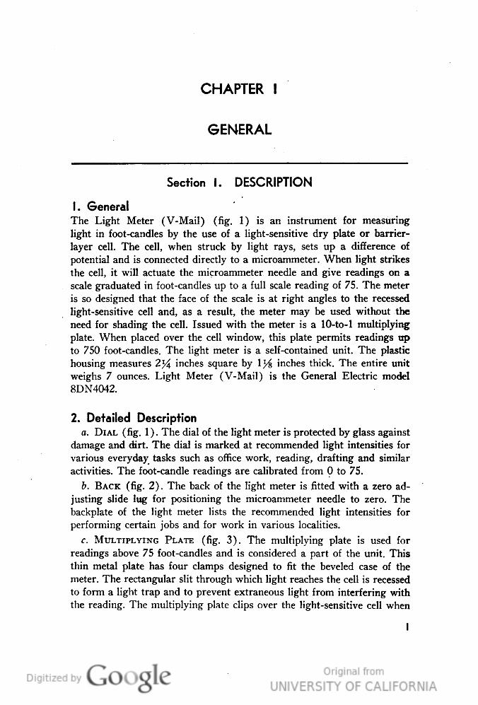
1. General
The Light Meter (V-Mail) (fig. 1) is an instrument for measuring
light in foot-candles by the use of a light-sensitive dry plate or barrier-
layer cell. The cell, when struck by light rays, sets up a difference of
potential and is connected directly to a microammeter. When light strikes
the cell, it will actuate the microammeter needle and give readings on a
scale graduated in foot-candles up to a full scale reading of 75. The meter
is so designed that the face of the scale is at right angles to the recessed
light-sensitive cell and, as a result, the meter may be used without the
need for shading the cell. Issued with the meter is a 10-to-l multiplying
plate. When placed over the cell window, this plate permits readings up
to 750 foot-candles. The light meter is a self-contained unit. The plastic
housing measures 2^4 inches square by 1% inches thick. The entire unit
weighs 7 ounces. Light Meter (V-Mail) is the General Electric model
8DN4042.
2. Detailed Description
a. DIAL (fig. 1). The dial of the light meter is protected by glass against
damage and dirt. The dial is marked at recommended light intensities for
various everyday tasks such as office work, reading, drafting and similar
activities. The foot-candle readings are calibrated from 0 to 75.
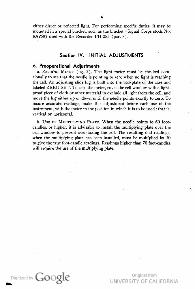
b. BACK (fig. 2). The back of the light meter is fitted with a zero ad-
justing slide lug for positioning the microammeter needle to zero. The
backplate of the light meter lists the recommended light intensities for
performing certain jobs and for work in various localities.
c. MULTIPLYING PLATE (fig. 3). The multiplying plate is used for
readings above 75 foot-candles and is considered a part of the unit. This
thin metal plate has four clamps designed to fit the beveled case of the
meter. The rectangular slit through which light reaches the cell is recessed
to form a light trap and to prevent extraneous light from interfering with
the reading. The multiplying plate clips over the light-sensitive cell when
I
Genera
ted o
n 2
01
4-0
9-1
3 2
3:2
1 G
MT /
htt
p:/
/hd
l.hand
le.n
et/
20
27
/uc1
.b3
24
54
90
Public
Dom
ain
, G
oog
le-d
igit
ized
/
htt
p:/
/ww
w.h
ath
itru
st.o
rg/a
ccess
_use
#pd-g
oogle

4.
GENERAL
ELECTRI
RECOMMENDED MINIMUM FOOT CANDIES
UNDER 10-FOOT-CANDLES-CORRIDORS; AUDITORIUMS: RAIL-
WAY PLATFORMS: BULK STORAGE; COAL AND ASH HANDLING;
FOUNDRY CHARGING AND CASTING FLOORS
10 FOOT-CANDLES-SHiPHw. ANU RECEIVING; ROUGH BENCH
WORK. MACHINE WORK AND ASSEMBLY; WELDING: GLASS BLOWiNG;
PAINT MANUFACTURING; LEATHER TANNING AND STRETCHING.
20 FOOT-CANDLES-KNiTTiNG MA-
CHINES; PRINTING PRESSES; ElECTROTYP-
ING; LIGHT COLORED LEATHER AND CLOTH
FABRICATION; RUBBER PRODUCTS FABRICA-
TION: RETI" STORES. 2196830
50 FOQT-CANDLES-ORAFTiNG; FINE
MACHINE WORK. ASSEMBLY AND INSPEC- %H^P
TION; HAND SEWING; JEWELRY REPAIRING; SHOW CASES AND
SPECIAL DISPLAYS
100 FOOT-CANDLES AND ABOVE-PROOF READING AUTOMO-
BILE 800Y INSPECTION; DARK LEATHER CUTTING AND GRAD*G
TOBACCO GRADING; SHOW WINDOWS,
— BRIGHT DISTRICTS. LARGE'CITIES:
HOSPITAL OPERATING TABLES,
NELA PARK
CLEVELAND
i
)4|46]
'TL94846
I'iyure 2. Backplate of light meter.
in use. By multiplying the resulting meter scale readings by 10, approxi-
mate readings up to 750 foot-candles may be taken. When not in use, the
multiplying plate is clipped to the bottom of the meter.
Section II. APPLICATION
3. Varied Uses
The light meter has many uses as an illumination measuring instrument.
Its use in determining the efficiency of lighting methods has resulted in
more economical operation of various pieces of equipment under various
operating conditions. In V-Mail operations at Photomail stations, the
light meter is used in the following ways:
a. To determine the proper lamp voltage on Recorder PH-283.
Genera
ted o
n 2
01
4-0
9-1
3 2
3:2
1 G
MT /
htt
p:/
/hd
l.hand
le.n
et/
20
27
/uc1
.b3
24
54
90
Public
Dom
ain
, G
oog
le-d
igit
ized
/
htt
p:/
/ww
w.h
ath
itru
st.o
rg/a
ccess
_use
#pd-g
oogle

Figure 3. Liyht meter with multiplying plate.
b. To check the projection lamp efficiency with the voltmeter on En-
larger PH-285.
c. To match the illumination efficiency of individual lamps used in
Recorder PH-283.
d. To estimate the densities of rolls of film to be printed on continuous
Enlarger PH-285.
Section III. INSTALLATION AND ASSEMBLY
4. Unpacking and Checking
The light meter, when received, is packed in a small cardboard box, which
should be retained at all times for storage of the meter when not in use.
Check the meter for damage which may have resulted in shipping. To
determine the accuracy of the readings, check the meter against another of
definite known quality, or against a light source of uniform known
intensity.
5 Installation
The installation of the light meter will vary, depending upon the uses to
which it will be put. It may be hand-held to obtain illumination data of
Genera
ted o
n 2
01
4-0
9-1
3 2
3:2
1 G
MT /
htt
p:/
/hd
l.hand
le.n
et/
20
27
/uc1
.b3
24
54
90
Public
Dom
ain
, G
oog
le-d
igit
ized
/
htt
p:/
/ww
w.h
ath
itru
st.o
rg/a
ccess
_use
#pd-g
oogle
either direct or reflected light. For performing specific duties, it may be
mounted in a special bracket, such as the bracket (Signal Corps stock No.
8A258) used with the Recorder PH-283 (par. 7).
Section IV. INITIAL ADJUSTMENTS
6. Preoperational Adjustments
a. ZEROI'NG METER (fig. 2). The light meter must be checked occa-
sionally to see that the needle is pointing to zero when no light is reaching
the cell. An adjusting slide lug is built into the backplate of the case and
labeled ZERO SET. To zero the meter, cover the cell window with a light-
proof piece of cloth or other material to exclude all light from the cell, and
move the lug either up or down until the needle points exactly to zero. To
insure accurate readings, make this adjustment before each use of the
instrument, with the meter in the position in which it is to be used; that is,
vertical or horizontal.
b. USE OF MULTIPLYING PLATE. When the needle points to 60 foot-
candles, or higher, it is advisable to install the multiplying plate over the
cell window to prevent over-taxing the cell. The resulting dial readings,
when the multiplying plate has been installed, must be multiplied by 10
to give the true foot-candle readings. Readings higher than 70 foot-candles
will require the use of the multiplying plate.
Genera
ted o
n 2
01
4-0
9-1
3 2
3:2
1 G
MT /
htt
p:/
/hd
l.hand
le.n
et/
20
27
/uc1
.b3
24
54
90
Public
Dom
ain
, G
oog
le-d
igit
ized
/
htt
p:/
/ww
w.h
ath
itru
st.o
rg/a
ccess
_use
#pd-g
oogle

CHAPTER 2
OPERATING INSTRUCTIONS—STEP-BY-STEP
PROCEDURE
Note. For information on destroying this equipment to prevent enemy use, see
destruction notice at the front of this manual.
Figure 4. Light meter in recorder light testing bracket.
7. Regulating Voltage on Recorder PH-283
To adjust the lamp voltage on Recorder PH-283, follow the steps below:
a. Plug the recorder line cord into a suitable power source.
b. Press the noncrank button on the right side of the recorder, and open
the rear cover.
c. While the rear cover is open, raise the front cover.
d. Turn the main switch to ON.
e. Turn the motor switch to OFF, or remove the motor line cord plug
from its power receptacle.
Genera
ted o
n 2
01
4-0
9-1
3 2
3:2
1 G
MT /
htt
p:/
/hd
l.hand
le.n
et/
20
27
/uc1
.b3
24
54
90
Public
Dom
ain
, G
oog
le-d
igit
ized
/
htt
p:/
/ww
w.h
ath
itru
st.o
rg/a
ccess
_use
#pd-g
oogle

/. Select a clean sheet of white paper of the same tone value as the work
to be photographed.
g. Feed the sheet of paper into the recorder by turning the drive wheel
in a clockwise direction by hand, until the paper covers the drum area
behind the glass guide.
h. Remove the multiplying plate from the light meter, and install the
meter into the bracket (fig. 4).
i. Lower the meter and bracket into the front compartment of the re-
corder, and hook the tips of the bracket into the slots of the aperture
assembly (fig. 5).
RECORDER
FRONT COVER
OPENED
Figure 5. Meter bracket attached to Recorder PH-283.
j. With the meter bracket in place, move the bracket handle up and
down until the highest meter reading is obtained.
k. With the bracket held in this position, adjust the rheostat in the back
of the recorder (fig. 6) until the desired meter reading, which may vary
with different recorders, is obtained.
Genera
ted o
n 2
01
4-0
9-1
3 2
3:2
1 G
MT /
htt
p:/
/hd
l.hand
le.n
et/
20
27
/uc1
.b3
24
54
90
Public
Dom
ain
, G
oog
le-d
igit
ized
/
htt
p:/
/ww
w.h
ath
itru
st.o
rg/a
ccess
_use
#pd-g
oogle

Figure 6. Location of rheostat on Recorder PH-283.
Note. The predetermined light meter reading usually is marked on a piece of adhesive
tape and stuck to the recorder near the lamp failure reset switch.
/. When the rheostat is adjusted properly, remove the meter bracket
from the recorder.
m. Remove the light meter from the bracket, replace the multiplying
plate, and place the meter in its cardboard box.
n. Turn the recorder drive motor switch to ON, or plug the motor cord
into its power receptacle, to move the sheet of paper around the drum and
into the receiving hopper.
o. Turn the main switch to OFF.
p. Lower the front cover, and then the rear cover.
8. Regulating Voltage on Enlarger PH-285 (fig. 7)
The light intensity of the projection lamp of the continuous enlarger
requires an occasional check to determine the proper voltage for the lamp.
The voltmeter on Enlarger PH-285 is used to maintain constant illumina-
tion while the machine is in operation. If the lamp illumination efficiency
Genera
ted o
n 2
01
4-0
9-1
3 2
3:2
1 G
MT /
htt
p:/
/hd
l.hand
le.n
et/
20
27
/uc1
.b3
24
54
90
Public
Dom
ain
, G
oog
le-d
igit
ized
/
htt
p:/
/ww
w.h
ath
itru
st.o
rg/a
ccess
_use
#pd-g
oogle
Figure 7. Adjusting running voltage on Enlarger PH-285.
becomes impaired by long usage, it then becomes necessary to establish a
new running voltage to produce a beam of light of a definite intensity. To
readjust the running voltage, proceed as follows:
a. Set the light meter on top of the paper slit as shown in figure 7.
b. Insert a sheet of paper between the paper idler roller and the paper
signal switch actuating lever.
c. Adjust the lens aperture to the predetermined setting.
d. Push the START switch to turn on the enlarger light.
e. Turn off the room lights.
/. Adjust the rheostat until the light meter registers the desired foot-
candle reading.
Genera
ted o
n 2
01
4-0
9-1
3 2
3:2
1 G
MT /
htt
p:/
/hd
l.hand
le.n
et/
20
27
/uc1
.b3
24
54
90
Public
Dom
ain
, G
oog
le-d
igit
ized
/
htt
p:/
/ww
w.h
ath
itru
st.o
rg/a
ccess
_use
#pd-g
oogle

g. Note the voltage setting from the voltmeter to obtain the new run-
ning voltage.
h. Push the STOP button, and remove the sheet of paper from between
the paper idler roller and the paper signal switch.
i. Return the light meter to its cardboard box.
Note. Various other uses may be found for the light meter in connection with the
operation of Enlarger PH-285. Meter readings may be taken of the light beam projected
through the film, and average readings noted for several sections of the film. A chart
may be made for the film, showing approximate light transmission, to aid in determining
the voltage setting and lens setting for printing exposure. In using the light meter in
this manner, it is advisable to place a sheet of transluscent glass about midway between
the lens and the meter, to diffuse the light and prevent abrupt changes in the meter
readings.
9. Matching Recorder Lamps
The eight exposure lamps of Recorder PH-283 must be matched carefully,
to provide even illumination over the entire area of the document being
recorded. When one lamp burns out on the recorder, it is necessary to
replace the entire set of eight lamps to be certain the lamps are of equal
brilliance. The remainder of the lamps may be used later by rigging a
lampholder about 2 feet from a light meter, as shown in figure 8, and
recording the light intensity from individual lamps, matching them in sets
accordingly. The lampholder will require wiring to a power source. A 100-
to 125-ohm, 10- to 15-watt resistor must be installed in the lamp circuit
RECOBOER
L GMT METER
BLOCK OF WOOD -
WOOD BASE
Figure 8. Diagram for testing lamps.
Genera
ted o
n 2
01
4-0
9-1
3 2
3:2
1 G
MT /
htt
p:/
/hd
l.hand
le.n
et/
20
27
/uc1
.b3
24
54
90
Public
Dom
ain
, G
oog
le-d
igit
ized
/
htt
p:/
/ww
w.h
ath
itru
st.o
rg/a
ccess
_use
#pd-g
oogle
10
since the lamps are rated at 100 volts only, and should be tested at ap-
proximately 90 volts, which is the ordinary voltage applied to the lamps in
the recorder. The lamps so tested should be grouped according to their
brilliancy, and sets of eight bundled together for use in the recorder.
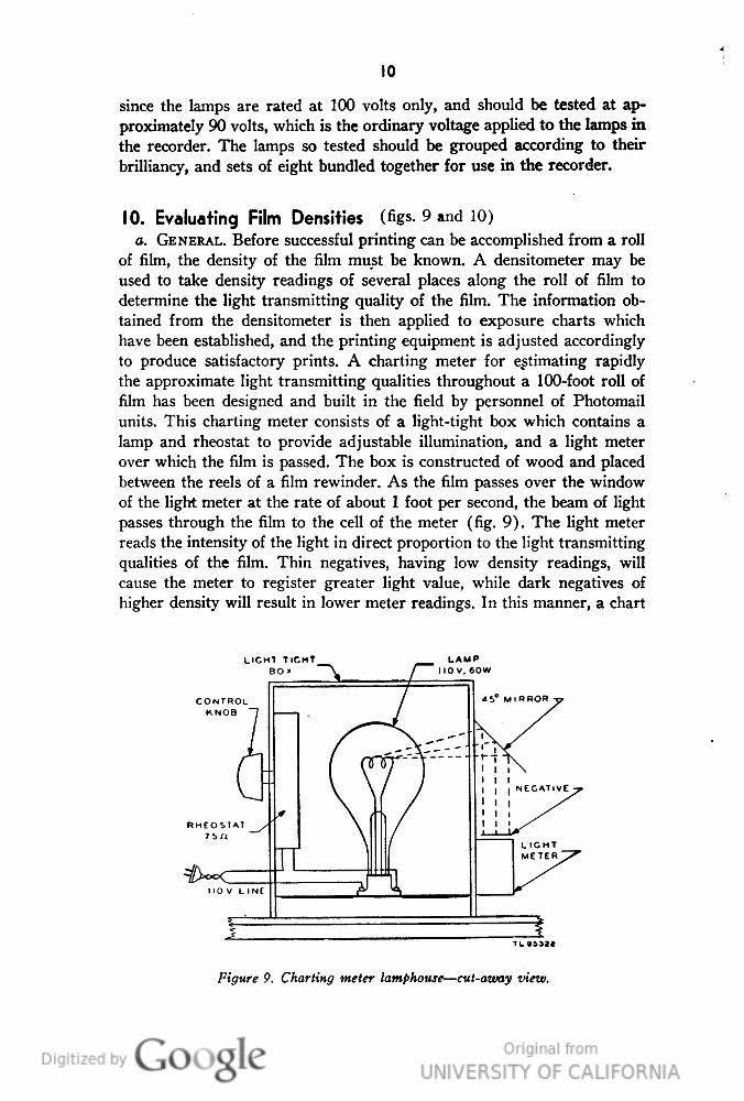
10. Evaluating Film Densities (figs. 9 and 10)
a. GENERAL. Before successful printing can be accomplished from a roll
of film, the density of the film must be known. A densitometer may be
used to take density readings of several places along the roll of film to
determine the light transmitting quality of the film. The information ob-
tained from the densitometer is then applied to exposure charts which
have been established, and the printing equipment is adjusted accordingly
to produce satisfactory prints. A charting meter for estimating rapidly
the approximate light transmitting qualities throughout a 100-foot roll of
film has been designed and built in the field by personnel of Photomail
units. This charting meter consists of a light-tight box which contains a
lamp and rheostat to provide adjustable illumination, and a light meter
over which the film is passed. The box is constructed of wood and placed
between the reels of a film rewinder. As the film passes over the window
of the light meter at the rate of about 1 foot per second, the beam of light
passes through the film to the cell of the meter (fig. 9). The light meter
reads the intensity of the light in direct proportion to the light transmitting
qualities of the film. Thin negatives, having low density readings, will
cause the meter to register greater light value, while dark negatives of
higher density will result in lower meter readings. In this manner, a chart
LIGHT TIGHT
BO»
CONTROL
KNOB
Figure 9. Charting meter lantphouse—cut-away view.
Genera
ted o
n 2
01
4-0
9-1
3 2
3:2
1 G
MT /
htt
p:/
/hd
l.hand
le.n
et/
20
27
/uc1
.b3
24
54
90
Public
Dom
ain
, G
oog
le-d
igit
ized
/
htt
p:/
/ww
w.h
ath
itru
st.o
rg/a
ccess
_use
#pd-g
oogle

II
may be made of the approximate light transmitting qualities of the nega-
tive throughout the entire roll.
Note. Two methods may be employed to adjust the light intensity of the lamp. Either
a rheostat can be incorporated in the lamp circuit, or the lamp can be supported on an
adjustable mount which can be moved closer to or further from the light meter.
Figure 10. Film charting meter—lay-out diagram.
b. STANDARDIZING LIGHT SOURCE. The light source in the charting
meter must be of known intensity to provide a controlling constant in
evaluating film density with the readings of the light meter. To provide a
standard check on the lamp of the charting meter, the following procedure
is advised:
(1) Select a short length of film with a density rating that will produce
satisfactory prints. In the case of dyeback film used in V-Mail operations,
a density rating of 1.15 will produce good results.
(2) Place this film on the charting meter and adjust the lamp until the
light meter foot-candle readings are in the lower third of the scale, or
approximately 20 foot-candles.
(3) With the lamp still on, replace the film with a selected strip, ap-
proximately 1 by 4 inches in size, of transluscent material such as empire
cloth or plastic, or a piece of processed film having approximately the
same optical density as the short length of film previously used.
(4) With the strip of transluscent material in place on the charting
meter, note the meter reading carefully and label the transluscent strip
with this reading.
Note. This transluscent strip will be the standard density strip to be used to stand-
ardize the lamp adjustment, and must be kept near the charting meter at all times.
(5) To standardize the charting meter lamp, place the transluscent
strip over the cell window of the light meter and turn on the light. The
lamp should be adjusted to produce a light meter reading to correspond to
the value marked on the strip label.
Note. Standardizing the light source may be necessary when a new lamp is installed
in the charting meter, or when adjustments have been made to the device.
Genera
ted o
n 2
01
4-0
9-1
3 2
3:2
1 G
MT /
htt
p:/
/hd
l.hand
le.n
et/
20
27
/uc1
.b3
24
54
90
Public
Dom
ain
, G
oog
le-d
igit
ized
/
htt
p:/
/ww
w.h
ath
itru
st.o
rg/a
ccess
_use
#pd-g
oogle

12
c. OPERATING CHARTING METER. To chart a 100-foot roll of film, pro-
ceed as follows:
(1) Install the roll on one spindle of the film rewind, so that the film
is pulled off the top of the reel.
(2) Standardize the lamp of the charting meter as described in para-
graph 126(5).
(3) Attach the end of the film to the take-up reel of the film rewind.
(4) Place the film over the light meter and between the two film guide
rollers.
(5) Turn the film charting lamp on.
(6) Rewind the film from the supply to the take-up reel at a rate of
approximately 1 foot per second and note the average of the light meter
readings.
Note. Meter readings should be taken at several places as the film passes over the
light meter. The minimum number of readings should be three, at each end and at the
middle of the film. Readings at every 10 to 20 feet are desirable, however.
(7) Enter these readings on a film chart and attach the chart to the
film to be sent to the printer, where the information can be used in making
prints from the film.
Genera
ted o
n 2
01
4-0
9-1
3 2
3:2
1 G
MT /
htt
p:/
/hd
l.hand
le.n
et/
20
27
/uc1
.b3
24
54
90
Public
Dom
ain
, G
oog
le-d
igit
ized
/
htt
p:/
/ww
w.h
ath
itru
st.o
rg/a
ccess
_use
#pd-g
oogle
CHAPTER 3
PREVENTIVE MAINTENANCE
Section I. PREVENTIVE MAINTENANCE TECHNIQUES
11. Meaning of Preventive Maintenance
Preventive maintenance may be denned as a series of operations performed
on equipment to minimize interruptions in service and to eliminate major
break-downs. The function of trouble shooting and repair, on the other
hand, is to locate and correct existing defects. This section of the manual
contains specific instructions and serves as a guide for personnel assigned
to perform the basic maintenance operations.
12. Preventive Maintenance for Light Meter
The most important factors in preventive maintenance for the light meter
are care and cleanliness. Because it is a precision instrument, the light
meter must be protected against jarring or being dropped, and extreme
changes in temperature. Keep the meter in its original cardboard carton
when not in use. If the light meter is left over night in the recorder meter
bracket, hang the bracket carefully on its two wall hooks with the handle
down, and cover the bracket with a cloth to prevent dust from settling on
the meter. Observe the following precautions.
a. Use care in handling the meter at all times.
b. Protect the cell from direct sunlight and high temperatures.
c. Protect the meter from sudden, extreme changes in temperatures.
d. Check the dial needle frequently for correct zeroing.
e. Allow for ceH fatigue under continued exposure.
/. Keep the multiplying plate attached to the meter case, at all times,
clipped to the cell window when in use; clipped to the case bottom when
not in use.
g. Store the meter in its cardboard carton when not in use.
h. Keep the meter case free from dust.
i. Do not allow the meter to come in contact with any oily substance.
Section II. LUBRICATION
13. Lubrication
No lubrication is required with the light meter, and the use of lubricants
will definitely harm the meter.
13
Genera
ted o
n 2
01
4-0
9-1
3 2
3:2
1 G
MT /
htt
p:/
/hd
l.hand
le.n
et/
20
27
/uc1
.b3
24
54
90
Public
Dom
ain
, G
oog
le-d
igit
ized
/
htt
p:/
/ww
w.h
ath
itru
st.o
rg/a
ccess
_use
#pd-g
oogle

CHAPTER 4
AUXILIARY EQUIPMENT
(NOT USED)
14
Genera
ted o
n 2
01
4-0
9-1
3 2
3:2
2 G
MT /
htt
p:/
/hd
l.hand
le.n
et/
20
27
/uc1
.b3
24
54
90
Public
Dom
ain
, G
oog
le-d
igit
ized
/
htt
p:/
/ww
w.h
ath
itru
st.o
rg/a
ccess
_use
#pd-g
oogle

CHAPTER 5
REPAIR INSTRUCTIONS
Note. Failure or unsatisfactory performance of equipment used by Army Ground
Forces and Army Service Forces will be reported on WD, AGO Form 468 (Unsatis-
factory Equipment Report) ; by Army Air Forces, on Army Air Forces Form 54 (Un-
satisfactory Report). If either form is not available, prepare the data according to the
sample form reproduced in figure 12.
TRANSLUSCENT
METAL SURFACE
MICRCAMMETER
Figure 11. Light meter—wiring diagram.
14. Theory of Equipment—Electrical, Optical, and
Mechanical Design (fig- H)
a. GENERAL DESIGN. The light meter contains two basic electrical units,
the light-sensitive cell and the microammeter. The light-sensitive cell is
connected in series with the' microammeter.
'(1) Cell. In general, the light-sensitive cell consists of a layer of
selenium deposited on the surface of a steel plate; over this layer of se-
lenium, transluscent layers of conducting metals are deposited. These
metals make up the negative terminal of the cell, the active area of which
measures 1.1 square inches. When light falls upon the cell, a photoelectric
effect is produced which causes a current to flow through the microam-
meter connected directly to the cell.
15
Genera
ted o
n 2
01
4-0
9-1
3 2
3:2
2 G
MT /
htt
p:/
/hd
l.hand
le.n
et/
20
27
/uc1
.b3
24
54
90
Public
Dom
ain
, G
oog
le-d
igit
ized
/
htt
p:/
/ww
w.h
ath
itru
st.o
rg/a
ccess
_use
#pd-g
oogle

16
(2) Microammeter. The microammeter is so calibrated that the indica-
tion on the scale is proportional to the light flux falling on the light-
sensitive cell.
b. SPECIAL CHARACTERISTICS. (1) Cell Fatigue. The cell in the light
meter undergoes no permanent change as a result of fatigue. As in all
other cells of this type, however, there is a slight change in current and in
indication under continued exposure. At 60 foot-candles for 1 hour, this
fatigue amounts to a decrease of about 5 percent, 3 or 4 percent of which
occurs in the first 15 minutes. After a period of 1 hour, the reading is
practically constant. At lower illumination levels, this effect is less pro-
nounced. All light meters are calibrated at 20 and 60 foot-candles after
exposure to 20 foot-candles of light at a color temperature of 2700° K for
15 minutes.
(2) Calibration tolerance. Manufacturing tolerances in cells and in in-
struments result in a variation in indication of ± 7.5 percent, but most
meters fall within much closer limits.
(3) Angle of incidence. Light meters are affected by the angle at which
the light strikes the cell window. As the surface of the glass is turned to
a more oblique angle, more of the light is reflected from the surface and is
not recorded by the instrument. It is necessary, therefore, to use the light
meter whenever possible with the light beam striking the cell window at
or near a perpendicular.
(4) Temperature characteristics. The characteristics of the cell depend
largely upon temperature and the resistance in the external circuit. The
resistance of the microammeter has been chosen to make as favorable a
temperature characteristic as possible, which is approximately 300 ohms.
With this resistance in the external circuit of the cell, the error due to
temperature is very small. It will be within ± 4 percent, from 0 to 100° F.
For ranges of temperature under which the light meter ordinarily will be
used, the error is within 1 or 2 percent.
- (5) Spectral response. The most important variable from a photometric
standpoint is the degree of correspondence between the response of the
cell and the response of the human eye to various colors. It is character-
istic of all light-sensitive cells of this type that hone of them follow exactly
the spectral response curve of the eye. Filters may be used to correct this
difference, but for ordinary purposes they are not required. The light
meter responds favorably to the spectral response curve of the human eye
under ordinary artificial lighting conditions.
15. Trouble Shooting
The trouble shooting required for the light meter is understandably minor.
However, if the meter reading is high on the scale, this condition should
Genera
ted o
n 2
01
4-0
9-1
3 2
3:2
2 G
MT /
htt
p:/
/hd
l.hand
le.n
et/
20
27
/uc1
.b3
24
54
90
Public
Dom
ain
, G
oog
le-d
igit
ized
/
htt
p:/
/ww
w.h
ath
itru
st.o
rg/a
ccess
_use
#pd-g
oogle

17
be corrected by installing the multiplying plate. If, after prolonged usage,
the meter readings tend to be low, allowance should be made for cell
fatigue, as described in paragraph I4b(l).
16. Repair
Under no circumstances should the light meter be repaired in the field.
17. Unsatisfactory Equipment Report
a. When trouble in equipment used by Army Ground Forces or Army
Service Forces occurs more often than repair personnel feel is normal,
WAP DEPARTMENT UNSATISFACTORY EQUIPMENT REPORT
lf
oo, QQT*i 5iG/v*i- PHOTO MAO. Co A PQ OOP N.TW YO^K, A/ y
\5iG/v/K OFFIC^ (ntovGH CHAMN£L$)
COMPLETE MAJOR ITEM
PH-OOO
c-/
A y z. Co
t9</</
NOMENCLATURE OF DETECTIVE COMPONENT
SC° STOCK A/o 7AOOQ/AO I PLATTF/N/
B c.
LENGTH Or SERVICE
DESCRIPTION OF TROUBLE AND PROBABLE CAUSE
co«r/«.r.5
**0 Ptrttfy COUSINS POOR. co/v?/«.r
UNUSUAL SERVICE CONDITIONS
£>PoSi//?f5
THC
fc-
Iteviy Typf of //<»TE/?MI. FQ/? co<v7/icr5,^i/g A
TO
Officer
OR1O1NATINO
UT LT
o. OOOTH
>i. Co.
INSTRUCTIONS
3 Rkit toit* —lU ilw b. »—d toi i»(Hirti''iJ InituiM .-nlatFd fnni*iat d»t«1» a* hl'"Mt'»^Ip.id!'.QBibm'*-'S'n^ b'* t™"1 'bnI>W ^ "**d ** '"*
'po.i in 'K* .HUF of parti and i^uipncat It ot« Bn* „ dupiieot» thiiiuoh lommnnd fbonu*l. ... ih. . b.lH ..( 'u'^n
Figure 12. Unsatisfactory Equipment Report.
Genera
ted o
n 2
01
4-0
9-1
3 2
3:2
2 G
MT /
htt
p:/
/hd
l.hand
le.n
et/
20
27
/uc1
.b3
24
54
90
Public
Dom
ain
, G
oog
le-d
igit
ized
/
htt
p:/
/ww
w.h
ath
itru
st.o
rg/a
ccess
_use
#pd-g
oogle

18
War Department Unsatisfactory Equipment Report, WD, AGO Form 468
should be filled out and forwarded through channels to the Chief Signal
Officer, Washington 25, D. C.
b. When trouble in equipment used by Army Air Forces occurs more
often than repair personnel feel is normal, Army Air Forces Form 54
should be filled out and forwarded through channels.
c. If either form is not available, WD, AGO Form 468 (fig. 12) may be
reproduced, filled out, and forwarded through channels. When Army Air
Forces Form 54 is required but unavailable, reproduce Form 468 and
forward it through channels in accordance with directions on Form 468.
Genera
ted o
n 2
01
4-0
9-1
3 2
3:2
2 G
MT /
htt
p:/
/hd
l.hand
le.n
et/
20
27
/uc1
.b3
24
54
90
Public
Dom
ain
, G
oog
le-d
igit
ized
/
htt
p:/
/ww
w.h
ath
itru
st.o
rg/a
ccess
_use
#pd-g
oogle

APPENDIX
MAINTENANCE PARTS LIST AND REFERENCES
1. Maintenance Parts List
No maintenance parts list is applicable to this equipment.
2. References
The operator will find pertinent additional data in the publications listed
below to aid in the efficient operation of this equipment.
a. TM 1-219, Basic Photography.
b. TM 11-2301, Densitometer PH-326.
c. TM 11-2351, Exposure Meters PH-77, PH-77-A, PH-77-C, and
PH-252-A.
d. AR 380-5, Safeguarding Military Information.
U. S. Government Printing Office: 1945. 628023—TM26
19
Genera
ted o
n 2
01
4-0
9-1
3 2
3:2
2 G
MT /
htt
p:/
/hd
l.hand
le.n
et/
20
27
/uc1
.b3
24
54
90
Public
Dom
ain
, G
oog
le-d
igit
ized
/
htt
p:/
/ww
w.h
ath
itru
st.o
rg/a
ccess
_use
#pd-g
oogle

Genera
ted o
n 2
01
4-0
9-1
3 2
3:2
2 G
MT /
htt
p:/
/hd
l.hand
le.n
et/
20
27
/uc1
.b3
24
54
90
Public
Dom
ain
, G
oog
le-d
igit
ized
/
htt
p:/
/ww
w.h
ath
itru
st.o
rg/a
ccess
_use
#pd-g
oogle

Genera
ted o
n 2
01
4-0
9-1
3 2
3:3
8 G
MT /
htt
p:/
/hd
l.hand
le.n
et/
20
27
/uc1
.b3
24
54
90
Public
Dom
ain
, G
oog
le-d
igit
ized
/
htt
p:/
/ww
w.h
ath
itru
st.o
rg/a
ccess
_use
#pd-g
oogle

Genera
ted o
n 2
01
4-0
9-1
3 2
3:2
2 G
MT /
htt
p:/
/hd
l.hand
le.n
et/
20
27
/uc1
.b3
24
54
90
Public
Dom
ain
, G
oog
le-d
igit
ized
/
htt
p:/
/ww
w.h
ath
itru
st.o
rg/a
ccess
_use
#pd-g
oogle

Genera
ted o
n 2
01
4-0
9-1
3 2
3:2
2 G
MT /
htt
p:/
/hd
l.hand
le.n
et/
20
27
/uc1
.b3
24
54
90
Public
Dom
ain
, G
oog
le-d
igit
ized
/
htt
p:/
/ww
w.h
ath
itru
st.o
rg/a
ccess
_use
#pd-g
oogle


