Download - Waterworks Dresden Hosterwitz
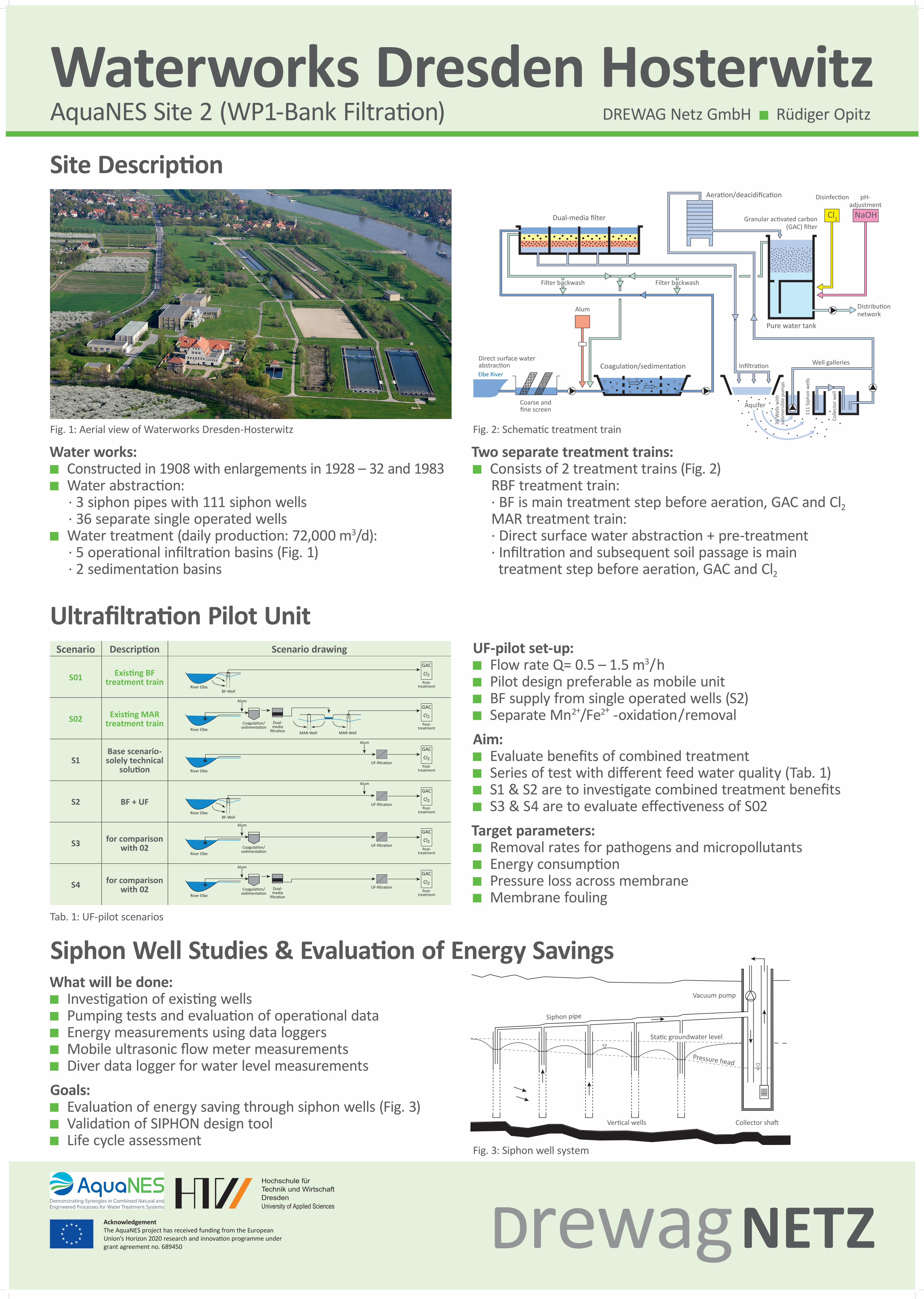
Scenario Description Scenario drawing
S01 Existing BFtreatment train
S02 Existing MARtreatment train
S1Base scenario-solely technical
solution
S2 BF + UF
S3 for comparisonwith 02
S4 for comparison with 02
Waterworks Dresden HosterwitzDREWAG Netz GmbH Rüdiger Opitz
Water works:Constructed in 1908 with enlargements in 1928 – 32 and 1983Water abstraction:
· 3 siphon pipes with 111 siphon wells · 36 separate single operated wells
Water treatment (daily production: 72,000 m3/d): · 5 operational infiltration basins (Fig. 1) · 2 sedimentation basins
Fig. 1: Aerial view of Waterworks Dresden-Hosterwitz
AquaNES Site 2 (WP1-Bank Filtration)
Cl2
Elbe River
Dual-media filter
Aeration/deacidification
Granular activated carbon (GAC) filter
Distribution network
Disinfection
NaOH
pH-adjustment
Pure water tank
Well galleriesInfiltration
Aquifer
Coagulation/sedimentation
Alum
Filter backwash Filter backwash
Coarse and fine screen
Direct surface water abstraction
Fig. 2: Schematic treatment train
Two separate treatment trains: Consists of 2 treatment trains (Fig. 2)
RBF treatment train: · BF is main treatment step before aeration, GAC and Cl2 MAR treatment train: · Direct surface water abstraction + pre-treatment · Infiltration and subsequent soil passage is main treatment step before aeration, GAC and Cl2
Siphon Well Studies & Evaluation of Energy SavingsWhat will be done:
Investigation of existing wells Pumping tests and evaluation of operational dataEnergy measurements using data loggersMobile ultrasonic flow meter measurementsDiver data logger for water level measurements
Goals:Evaluation of energy saving through siphon wells (Fig. 3)Validation of SIPHON design toolLife cycle assessment
Site Description
Ultrafiltration Pilot UnitUF-pilot set-up:
Flow rate Q= 0.5 – 1.5 m3/hPilot design preferable as mobile unitBF supply from single operated wells (S2)Separate Mn2+/Fe2+ -oxidation/removal
Aim:Evaluate benefits of combined treatment Series of test with different feed water quality (Tab. 1)S1 & S2 are to investigate combined treatment benefitsS3 & S4 are to evaluate effectiveness of S02
Target parameters:Removal rates for pathogens and micropollutantsEnergy consumptionPressure loss across membrane Membrane fouling
Tab. 1: UF-pilot scenarios
Fig. 3: Siphon well system
AcknowledgementThe AquaNES project has received funding from the European Union’s Horizon 2020 research and innovation programme under grant agreement no. 689450
Siphon pipe
Vacuum pump
Collector shaftVertical wells
Pressure head
Static groundwater level
Post-treatment
GAC
Cl2
Post-treatment
GAC
Cl2Coagulation/sedimentation
Alum
River Elbe
Alum
Alum
BF-WellRiver Elbe
UF-filtration
UF-filtration
River Elbe
MAR-WellMAR-Well
BF-WellRiver Elbe
UF-filtration
UF-filtration
Post-treatment
GAC
Cl2
Post-treatment
GAC
Cl2
Post-treatment
GAC
Cl2
Post-treatment
GAC
Cl2
Coagulation/sedimentation
Alum
River Elbe
Dual-mediafiltration
Coagulation/sedimentation
Alum
River Elbe
Dual-mediafiltration
Post-treatment
GAC
Cl2
Post-treatment
GAC
Cl2Coagulation/sedimentation
Alum
River Elbe
Alum
Alum
BF-WellRiver Elbe
UF-filtration
UF-filtration
River Elbe
MAR-WellMAR-Well
BF-WellRiver Elbe
UF-filtration
UF-filtration
Post-treatment
GAC
Cl2
Post-treatment
GAC
Cl2
Post-treatment
GAC
Cl2
Post-treatment
GAC
Cl2
Coagulation/sedimentation
Alum
River Elbe
Dual-mediafiltration
Coagulation/sedimentation
Alum
River Elbe
Dual-mediafiltration


