Download - Waveguide Interdigital Filters - W1GHZ.org
Jan/Feb 1999 3
Build sturdy, predictable microwave filters fromwaveguide. Here are designs for three bands:
1296, 2304 and 3456 MHz.
By Paul Wade, W1GHZ (N1BWT)
161 Center RdShirley, MA [email protected]
WaveguideInterdigital Filters
1Notes appear on page 8.
Most microwave transverters,especially the “no-tune”variety, need some additional
filtering to operate in locations with“RF pollution”—accessible mountain-tops are notoriously bad environments.Waveguide post filters provide supe-rior performance at 10 GHz1 and5760 MHz,2 but become large andheavy at lower frequencies. Inter-digital filters are excellent performersat the lower microwave frequencies,3
but the usual construction techniquesrequire some machining, mostlytedious tapping of threads in many
holes. One of the beauties of waveguidefilters is that the basic structure is ac-curately defined by the waveguide, soconstruction requires only drilling andsoldering. Since surplus waveguide isreasonably plentiful, I wondered if itcould be used to build interdigital fil-ters for the lower microwave bands. Aswe shall see, my experiments werequite successful.
Interdigital FiltersThe basic structure of an inter-
digital filter, shown in Fig 1, is a groupof coupled resonators in a metal hous-ing. Each resonator is an electrical λ/4long, but physically shortened bycapacitance at the open end. The reso-nators are interdigitated, with the po-sition of the open ends of the resonatorsalternating as depicted in Fig 1. (A
similar filter with all resonatorsaligned in the same direction is called acomb-line filter.) The coupling betweenresonators is controlled by their sepa-ration. Several methods are commonlyused to make input and output connec-tions, but a simple one is to use taps onthe input and output resonators.
The starting dimension for aninterdigital filter is the width of thehousing, which should be λ/4 at theoperating frequency. All of theother dimensions are interrelated—a change in one affects others—so thatempirical design of a filter would bedifficult and frustrating. Fortunately,computer programs are available todesign interdigital filters. A BASICprogram,4 by N6JH, appears in hamradio magazine. I translated thisinto PASCAL and compiled it. My
4 QEX
version, INTFIL.EXE, is available fordownloading at http://www.qsl.net/~n1bwt/intfil.zip. One 1296 MHzfilter that I built using this programwas carefully measured using anautomatic network analyzer and foundto match the predicted performance al-most perfectly with no tuning. Thisgave me confidence in the accuracy ofthe program.
Filter DesignThe first part of filter design is the
same for all types of filters—calcula-tion of coupling coefficients and otherparameters to achieve the desired per-formance. These are tabulated in TheARRL Handbook5 and other referencebooks6 for the most common types offilters: the Butterworth (maximally-flat) and the Chebyshev response,which trades some passband ripple(amplitude variation) for somewhatsteeper skirts at the passband edges.The tabulated parameters, gmn, are fora normalized prototype filter, so thatfurther calculations are required tofind actual component values for adesired frequency and impedance.
The second part of filter design is toconvert the normalized parametersinto component values or physical di-mensions. The calculations are quitetedious, so graphical solutions wereoften published7 before computerswere commonly available. Now thesecalculations are easily performed on aPC, allowing us to evaluate multiplefilter designs before choosing one tobuild.
Design of an interdigital filter be-gins with the choice of a requiredbandwidth. Simple filter programssuch as INTFIL are only reliable forbandwidths between about 1% and10% of the center frequency, and very-narrow-bandwidth filters are lossyand require tight tolerances in con-struction. Therefore, a 3% to 5% band-width is recommended as a good start-ing point. The next step is to decidehow steeply the skirts roll off at thepassband edges. For example, steeperskirts are required to reject an image
Table 1: Waveguide Dimensions for Interdigital Filters
Frequency
Waveguide Wide Dimension (λ/4, MHz)
WR-340 3.4″ 868WR-284 2.84″ 1039WR-229 2.29″ 1289WR-187 1.872″ 1577WR-159 1.59″ 1857WR-137 1.372″ 2152WR-112 1.12″ 2636WR-90 0.90″ 3280WR-75 0.75″ 3937WR-62 0.622″ 4747WR-50 0.51″ 5789Fig 1—Interdigital filter cross-section
sketch.
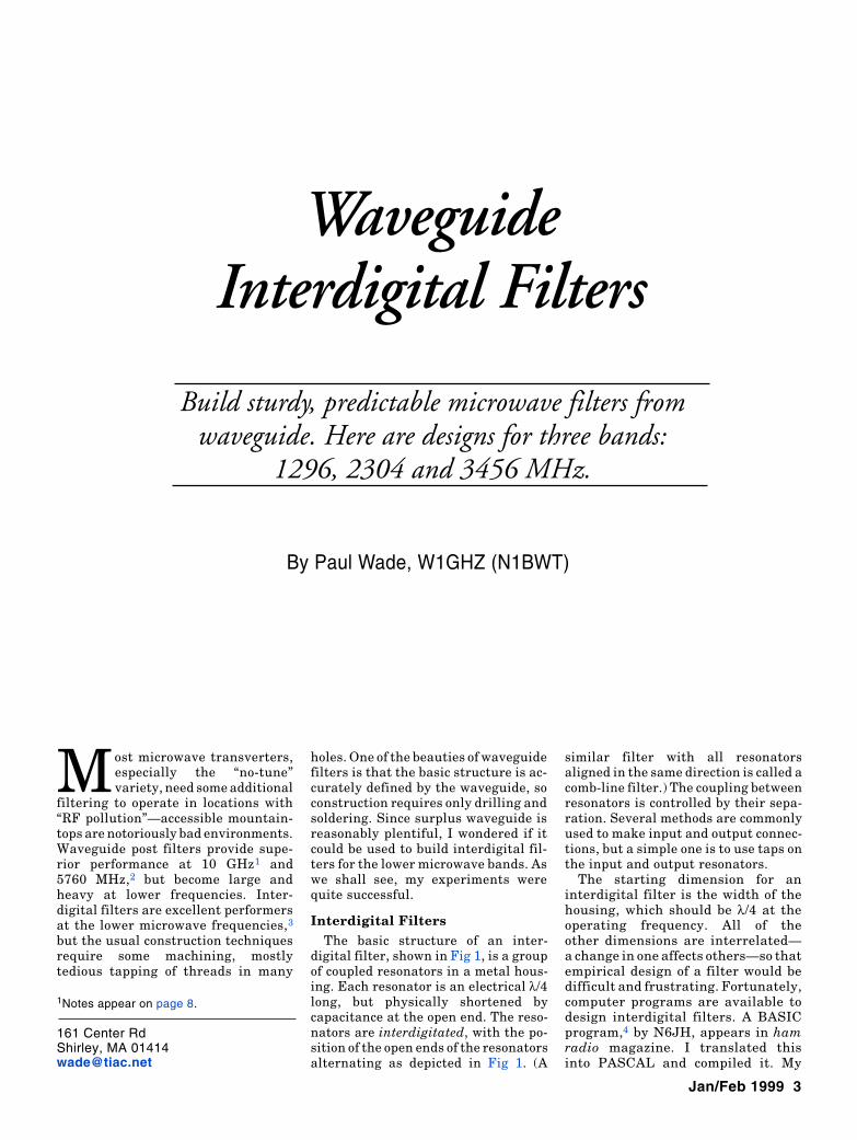
Fig 2—Performance of 1296-MHz filter—WR-229 waveguide.
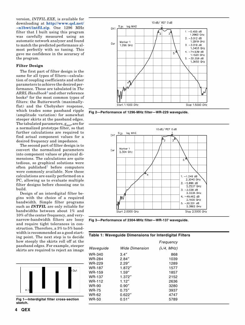
Fig 3—Performance of 2304-MHz filter—WR-137 waveguide.
Jan/Feb 1999 5
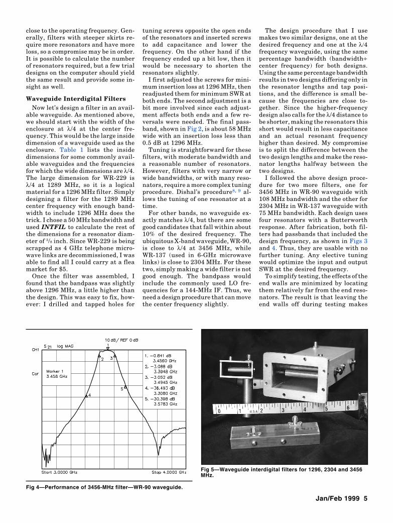
Fig 4—Performance of 3456-MHz filter—WR-90 waveguide.
close to the operating frequency. Gen-erally, filters with steeper skirts re-quire more resonators and have moreloss, so a compromise may be in order.It is possible to calculate the numberof resonators required, but a few trialdesigns on the computer should yieldthe same result and provide some in-sight as well.
Waveguide Interdigital FiltersNow let’s design a filter in an avail-
able waveguide. As mentioned above,we should start with the width of theenclosure at λ/4 at the center fre-quency. This would be the large insidedimension of a waveguide used as theenclosure. Table 1 lists the insidedimensions for some commonly avail-able waveguides and the frequenciesfor which the wide dimensions are λ/4.The large dimension for WR-229 isλ/4 at 1289 MHz, so it is a logicalmaterial for a 1296 MHz filter. Simplydesigning a filter for the 1289 MHzcenter frequency with enough band-width to include 1296 MHz does thetrick. I chose a 50 MHz bandwidth andused INTFIL to calculate the rest ofthe dimensions for a resonator diam-eter of 3/8 inch. Since WR-229 is beingscrapped as 4 GHz telephone micro-wave links are decommissioned, I wasable to find all I could carry at a fleamarket for $5.
Once the filter was assembled, Ifound that the bandpass was slightlyabove 1296 MHz, a little higher thanthe design. This was easy to fix, how-ever: I drilled and tapped holes for
Fig 5—Waveguide interdigital filters for 1296, 2304 and 3456MHz.
tuning screws opposite the open endsof the resonators and inserted screwsto add capacitance and lower thefrequency. On the other hand if thefrequency ended up a bit low, then itwould be necessary to shorten theresonators slightly.
I first adjusted the screws for mini-mum insertion loss at 1296 MHz, thenreadjusted them for minimum SWR atboth ends. The second adjustment is abit more involved since each adjust-ment affects both ends and a few re-versals were needed. The final pass-band, shown in Fig 2, is about 58 MHzwide with an insertion loss less than0.5 dB at 1296 MHz.
Tuning is straightforward for thesefilters, with moderate bandwidth anda reasonable number of resonators.However, filters with very narrow orwide bandwidths, or with many reso-nators, require a more complex tuningprocedure. Dishal’s procedure8, 9 al-lows the tuning of one resonator at atime.
For other bands, no waveguide ex-actly matches λ/4, but there are somegood candidates that fall within about10% of the desired frequency. Theubiquitous X-band waveguide, WR-90,is close to λ/4 at 3456 MHz, whileWR-137 (used in 6-GHz microwavelinks) is close to 2304 MHz. For thesetwo, simply making a wide filter is notgood enough. The bandpass wouldinclude the commonly used LO fre-quencies for a 144-MHz IF. Thus, weneed a design procedure that can movethe center frequency slightly.
The design procedure that I usemakes two similar designs, one at thedesired frequency and one at the λ/4frequency waveguide, using the samepercentage bandwidth (bandwidth÷center frequency) for both designs.Using the same percentage bandwidthresults in two designs differing only inthe resonator lengths and tap posi-tions, and the difference is small be-cause the frequencies are close to-gether. Since the higher-frequencydesign also calls for the λ/4 distance tobe shorter, making the resonators thisshort would result in less capacitanceand an actual resonant frequencyhigher than desired. My compromiseis to split the difference between thetwo design lengths and make the reso-nator lengths halfway between thetwo designs.
I followed the above design proce-dure for two more filters, one for3456 MHz in WR-90 waveguide with108 MHz bandwidth and the other for2304 MHz in WR-137 waveguide with75 MHz bandwidth. Each design usesfour resonators with a Butterworthresponse. After fabrication, both fil-ters had passbands that included thedesign frequency, as shown in Figs 3and 4. Thus, they are usable with nofurther tuning. Any elective tuningwould optimize the input and outputSWR at the desired frequency.
To simplify testing, the effects of theend walls are minimized by locatingthem relatively far from the end reso-nators. The result is that leaving theend walls off during testing makes
6 QEX
little difference in performance. Ilocated the end walls one inch from theend resonators in the 1296 MHz filter,and could find only a slight perfor-mance difference with the end walls inplace. There was no detectable differ-ence for the higher frequency filters.Of course, the end walls should be in-stalled for operation; stray leakagecould otherwise negate the effect ofthe filter.
ConstructionThe three completed filters are
shown in Fig 5. Each resonator is at-tached by a screw through a narrowwall of the waveguide and the coaxialconnectors are mounted in a wide wallof the waveguide with short leads tothe tap points on the end resonators.
Resonator lengths and spacings arefairly critical, so accurate measure-ment is needed. The holes are bestmade with a drill press (see thesidebar “Tools for Interdigital FilterConstruction.” Start with a centerdrill or small drill bit to spot the hole,then follow with a drill bit of the de-sired diameter. The mounting holes inthe end of the resonators should betapped and countersunk slightly, socontact is made around the resonatorperimeter. For initial testing, I don’tsolder the input and output connec-tions, but rather make them slightlylong with a sharp point contacting thetap point on the resonators.
Using waveguide as the housingmakes the filters easy to build, andresults in a robust, stable filter, suit-able for rover operations. Some of myprevious experiments in filter con-struction using hobby brass and PCboard were less successful due tomechanical instability: Vibrations orthe weight of connecting coax cablesaffected their performance. One nota-bly bad filter was so unstable that thefrequency response would vary duringmeasurement.
After building and testing the filtersin Fig 5, I wondered if there was aneven simpler way to make these filters.Since the resonator length for the 3456MHz filter is just a hair’s breadth over3/4 inch, perhaps an ordinary 3/4-inch-long, 1/4-inch-diameter threaded stand-off could be used as a resonator. Theresonator spacings and the tap-pointdimensions are the critical ones, so Icalculated a filter with 75 MHz band-width using 1/4-inch-diameter resona-tors, then built it with threadedstandoffs. It took less than an hourto complete. A quick measurementshowed nearly 3 dB loss at 3456 MHz,
Table 2: Waveguide Interdigital Filter Examples
Waveguide WR-229 WR-137 WR-90 WR-90Target Frequency 1289 2304 3456 3456 MHzBandwidth 50 75 108 79 MHz
Resonator (Designed for waveguide λ/4)Diameter 0.375 0.25 0.1875 0.25 inchesEnd Length 1.983 1.099 0.732 0.727 inchesInterior Length 1.971 1.095 0.73 0.728 inchesTap Point 0.23 0.127 0.089 0.089 inchesλ/4 Frequency 1289 2155 3280 3280 MHzBandwidth same 70 100 75 MHz
Resonator (Designed for target frequency)Diameter ″ 0.25 0.1875 0.25 inchesEnd Length ″ 1.187 0.777 0.773 inchesInterior Length ″ 1.183 0.775 0.772 inchesTap Point ″ 0.136 0.093 0.095 inchesSpacing 1-2,3-4 1.47 0.864 0.58 0.653 inchesSpacing 2-3 1.632 0.951 0.636 0.709 inches
Compromise DimensionsResonatorDiameter same 0.25 0.1875 0.25* inchesEnd Length ″ 1.144 0.756 0.75* inchesInterior Length ″ 1.14 0.752 0.75* inchesTap Point ″ 0.132 0.09 0.092 inches
Loss, Calculated 0.2 0.3 0.4 0.6 dBLoss, Measured 0.45 1.25 0.8 2.3 dBBandwidth, Measured 58 70 100 68 MHzLO Frequency 1152 2160 3312 3312 MHzLO Rejection, Calculated –59 –47 –34 –45 dBLO Rejection, Measured –75 –49 –36 –49 dB* = threaded standoff
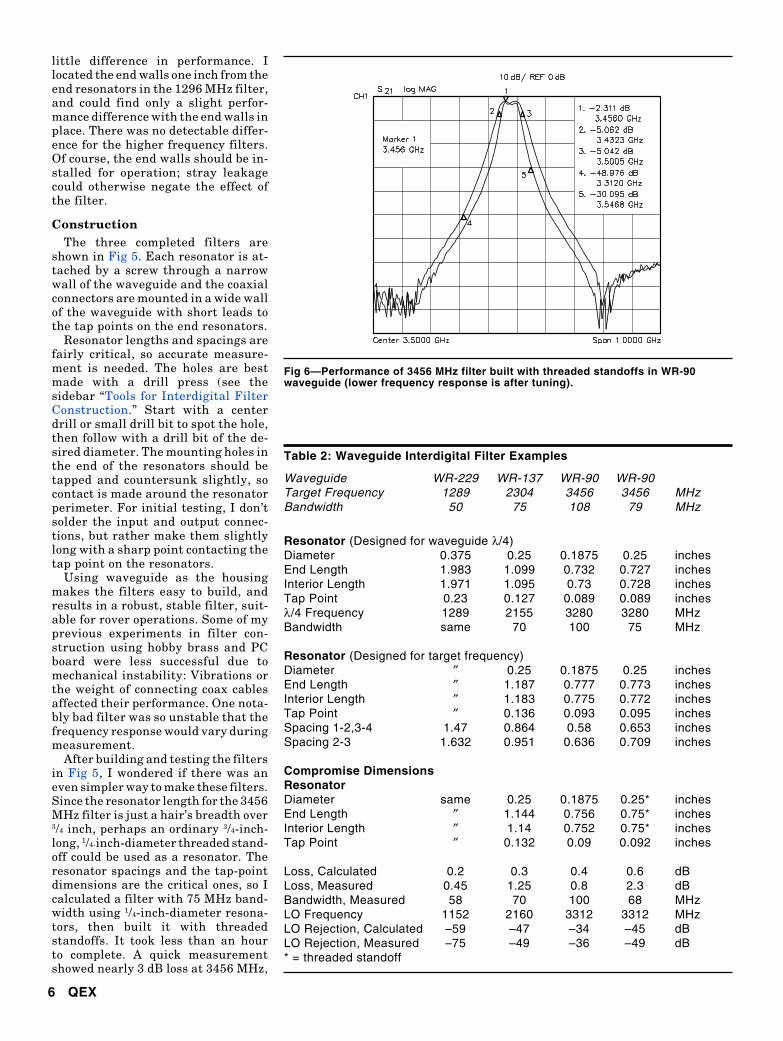
Fig 6—Performance of 3456 MHz filter built with threaded standoffs in WR-90waveguide (lower frequency response is after tuning).
Jan/Feb 1999 7
however, so I took it apart to add tun-ing screws to see if I could improve it.Careful tuning only reduced the loss to2.4 dB, versus 0.8 dB for the filter withmachined brass resonators. Fig 6shows the response before and aftertuning. The response is slightly higherin frequency before tuning, but other-wise there is little difference. I at-tribute the higher loss to three factors:• I arbitrarily designed this version
for a 75 MHz (2%) bandwidth, com-pared to a 108 MHz (3%) bandwidthfor the other 3456 MHz filter. Aspreviously mentioned, filters withnarrow bandwidths tend to be morelossy.
• The threaded standoffs are platedwith nickel, a lossy metal.
• The standoffs are chamfered at theends, so the contact area is smallerat the shorted end where currentsare highest.
PerformanceThe waveguide interdigital filters
exhibit excellent performance (asshown in Figs 2, 3, 4, and 6) with lowinsertion loss in the passband andhigh rejection of undesired frequen-cies. Steep skirts provide good rejec-tion of possible spurious signals, suchas LO leakage only 144 MHz awayfrom the operating frequency. LOrejection is much greater for the1296 MHz filter (–75 dB) than for theothers (–49 dB at 2304 MHz and–36 dB at 3456 MHz) because the rela-tive LO separation is much greater at1296 MHz. It’s 9% of the operating fre-quency at 1296 MHz, versus 6% at2304 MHz and 4% at 3456 MHz.
Table 2 lists the filter dimensionsand compares the measured perfor-mance with the design values, as cal-culated by INTFIL. The measured per-formance is quite close to the designvalues. The dimensions shown are forthe two designs for each filter, plus thecompromise values that I fabricated, toillustrate the design procedure.
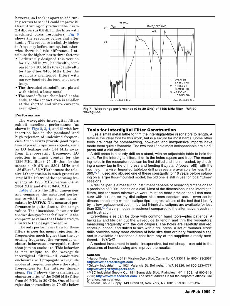
The only performance flaw for thesefilters is poor harmonic rejection. Atfrequencies much higher than the op-erating frequency, the waveguide en-closure behaves as a waveguide ratherthan just an enclosure. This behavioris not unique to the waveguideinterdigital filters—all conductiveenclosures will propagate waveguidemodes at frequencies above the cutofffrequencies for the interior dimen-sions. Fig 7 shows the transmissioncharacteristics of the 3456 MHz filterfrom 50 MHz to 20 GHz. Out-of-bandrejection is excellent (> 70 dB) below
Tools for Interdigital Filter ConstructionI use a small metal lathe to trim the interdigital-filter resonators to length. A
lathe is the ideal tool for this work, but is a luxury for most hams. Some othertools are great for homebrewing, however, and inexpensive imports havemade them quite affordable. The two that I find almost indispensable are a drillpress and a dial caliper.
A drill press is a sturdy drill on a stand, with an adjustable table to hold thework. For the interdigital filters, it drills the holes square and true. The mount-ing holes in the resonator rods can be first drilled and then threaded, by chuck-ing a screw tap in the drill press and feeding it by hand (power off!), with therod held in a vise. Imported tabletop drill presses are available for less than$60.A, B I used and abused one of these constantly for 16 years before splurg-ing on a larger floor-mounted model; the old one is still in use for local “Elmer”sessions.
A dial caliper is a measuring instrument capable of resolving dimensions toa precision of 0.001 inches on a dial. Most of the dimensions in the interdigitalfilters, and for much microwave work, must be more precise than I can mea-sure with a ruler, so my dial caliper also sees constant use. I even scribedimensions directly with the caliper tips—a gross abuse of the tool that I justifyby its low replacement cost. Imported 6-inch dial calipers are available for lessthan $20,C, D a very modest investment compared to the alternative: eyestrainand frustration.
Everything else can be done with common hand tools—plus patience. Ahacksaw and file can cut the waveguide to length and trim the resonators,measuring frequently with the dial calipers. The holes are carefully marked,center-punched, and drilled to size with a drill press. A set of “number-sized”drills provides many more choices of hole size than ordinary fractional sizes,and is available at reasonable cost from any of the suppliers already men-tioned.—W1GHZ
A modest investment in tools—inexpensive, but not cheap—can add to thepleasures of homebrewing and improve the results.
SourcesAHarbor Freight Tools, 3491 Mission Oaks Blvd, Camarillo, CA 93011; tel 800-423-2567;http://www.harborfreight.comBGrizzly Industrial, Inc, 1821 Valencia St, Bellingham, WA 98226; tel 800-523-4777;http://www.grizzlyimports.comCMSC Industrial Supply Co, 151 Sunnyside Blvd, Plainview, NY 11803; tel 800-645-7270; http://www.mscdirect.com. The street address is for the corporate offices. Callfor a location near you.DEastern Tool & Supply, 149 Grand St, New York, NY 10013; tel 800-221-2679.
Fig 7—Wide-range performance (0 to 20 GHz) of 3456-MHz filter—WR-90waveguide.
8 QEX
the passband and good above the pass-band up to about 6 GHz. Above 6 GHz,various waveguide modes are propa-gated and limit the attenuation.
resulting in a robust, high-perfor-mance filter.
Notes1G. Elmore, N6GN, “A Simple and Effective
Filter for the 10-GHz Band,” QEX, July1987, pp 3-5.
2P. Wade, N1BWT, “A Dual Mixer for 5760MHz with Filter and Amplifier,” QEX,August 1995, pp 9-13.
3R. Fisher, W2CQH, “Interdigital BandpassFilters for Amateur VHF/UHF Applica-tions,” QST, March 1968, p 32.
4J. Hinshaw, N6JH, and S. Monemzadeh,“Computer-Aided Interdigital BandpassFilter Design,” ham radio, January 1985,pp 12-26.
5R. Dean Straw, N6BV, Editor, The ARRL
Handbook for Radio Amateurs, ARRL,1997. See pp 30.22 and following.
6G. Matthei, L. Young, and E. M. T. Jones,Microwave Filters, Impedance MatchingNetworks, and Coupling Structures,McGraw-Hill, 1968.
7W.S. Metcalf, “Graphs Speed Design ofInterdigital Filters,” Microwaves, February1967, pp 91-95.
8M. Dishal, “Alignment and Adjustment ofSynchronously Tuned Multiple-Resonator-Circuit Filters,” Proc. IRE, November1951, pp 1448-1455.
9G. Matthei, L. Young, and E. M. T. Jones,Microwave Filters, Impedance MatchingNetworks, and Coupling Structures,McGraw-Hill, 1968, pp 668-673.
ConclusionGood filters are important for opera-
tion in locations with RF pollution,and are recommended when no-tunetransverters are followed by broad-band power amplifiers. Interdigitalfilters offer excellent performance forthe lower microwave bands. The fil-ters are easily constructed in a wave-guide housing without extensivemachining and require little tuning,


