EE 4
223/
5223
- Le
ctur
e 41
Wed
nesd
ay A
pril
22, 2
009
Ong
oing
Lis
t of T
opic
s:
•U
RL:
http
://w
ww
.ece
.mtu
.edu
/facu
lty/b
amor
k/E
E52
23/in
dex.
htm
•
Term
Pro
ject
- D
ue F
riday
(rem
ote
stud
ents
can
neg
otia
te e
xten
sion
)•
Loca
l pre
sent
atio
ns: 1
2:45
- 2:
45pm
Wed
; EE
RC
B45
•G
en P
rote
ctio
n - C
h. 8
, Bas
ic P
rote
ctio
n is
sues
(sum
mar
y fro
m p
rev
lect
ures
)•
IEE
E P
ublic
atio
n 95
TP10
2 - P
rot o
f Syn
ch G
ens
•IE
EE
C37
.102
- G
uide
for A
C G
ener
ator
Pro
tect
ion
•IE
EE
C37
.101
, C37
.106
- G
roun
d P
rote
ctio
n, A
bnor
mal
Fre
q P
rote
ctio
n•
Gro
undi
ng Is
sues
•N
otes
from
adj
unct
facu
lty, e
xam
ple
•O
ut-o
f-ste
p is
sues
- se
e al
so K
undu
r’s te
xt•
An
extre
me
exam
ple
of s
tray
volta
ge (n
eutra
l cur
rent
retu
rn th
ru g
nd p
aths
) •
Mot
or P
rote
ctio
n •
Arm
atur
e - s
imila
r stra
tegi
es a
s w
ith S
ynch
Mac
hine
s•
Bea
ring
Tem
p, v
ibra
tion
•O
ther
issu
es -
See
Ch.
11•
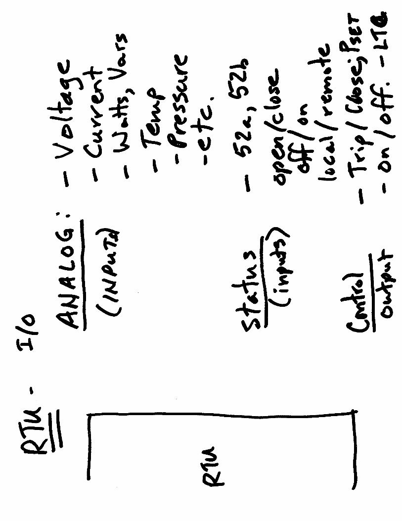
SC
AD
A b
asic
s, tr
ansd
ucer
s, s
calin
g fa
ctor
s fo
r rel
ays
and
SC
AD
AN
ext/L
ast:
•B
asic
DS
P re
lay
algo
rithm
s –
conv
ert s
ampl
es w
avef
orm
s in
to p
haso
r Vs
and
Is•
Rea
l-tim
e C
omm
unic
atio
ns fo
r pro
tect
ion
& c
ontro
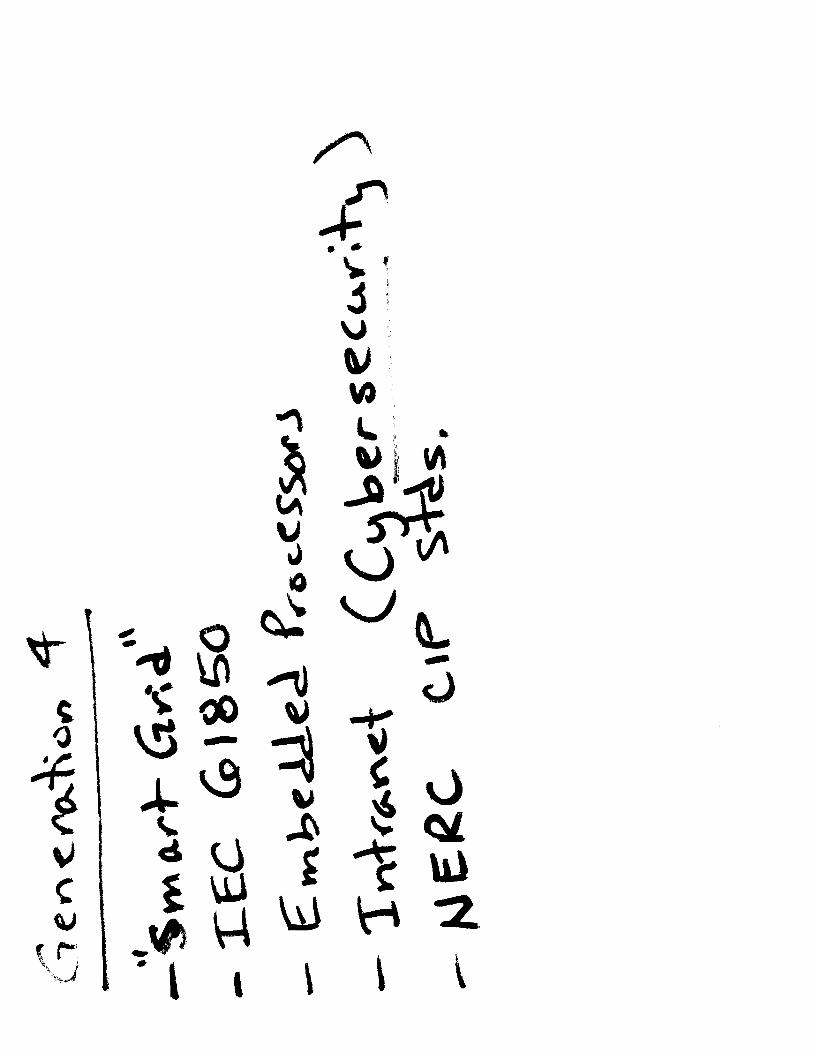
l, IE
C 6
1850


2
The SEL-710 Motor Protection Relay takes the next logical step in motor monitoring and control. While other motor relays assume a constant value for rotor resistance, the SEL-710 dynamically calculates motor slip and uses this information to precisely track motor temperature using the AccuTrack Thermal Model. Rotor resistance changes depending on slip and generates heat, especially during starting, when current and slip are highest. If your motor protection uses a constant rotor resistance for thermal protection, it could be off by a factor of three or more. By correctly calculating rotor temperature, the AccuTrack Thermal Model reduces the time between starts. It also gives the motor more time to reach its rated speed before tripping.
Functional Overview
AccuTrack™ Thermal Model
Saved Cooling Time
I2t Relay
SEL-710
Rotor Temperature
Motor Current
Rotor Resistance
Tem
pera
ture
(per
uni
t of l
imit)
0
0.1
0.2
0.3
0.5
0.6
0.8
0.9
1.0
0.7
Curr
ent
0.4
0
1
2
3
5
6
8
9
10
7
4
0 2 4 6 8 10 12 14 16 18 20
Seconds
Accurate thermal modeling provides protection that maximizes motor availability while providing excellent protection from damage.
87
* Optional Functions
** Select When Ordering
• Sequential Events Recorder
• Event Reports, Motor Start Reports, Motor Operating Statistics, Load Profiles, and Motor Start Trends
• SEL ASCII, Ethernet*, Modbus® TCP, IEC 61850*, Modbus RTU, Telnet, FTP, and DeviceNet™* Communications
• Front-Panel LED Programmable Targets
• Two Inputs and Three Outputs Standard
• I/O Expansion*—Additional Contact Inputs, Contact Outputs, Analog Inputs, Analog Outputs, and RTD Inputs
• Single or Dual Ethernet, Copper or Fiber-Optic Communications Port*
• Battery-Backed Clock, IRIG-B Time Synchronization**
• Instantaneous Metering
• Programmable Front Pushbuttons and LED Indicators
• Forward/Reverse Start Protection
• Advanced SELOGIC® Control Equations
• 32 Programmable Display Messages
• MIRRORED BITS® Communications
• Low-Voltage Starting
• Two-Speed Motor Protection
37 47
PhaseReversal
LC/71
UndercurrentUnderpower*
46
CurrentUnbalance
LoadJam
Load Jam
66
Starts-Per-HourTime Between
Starts
49
Motor ThermalOverload
59
Overvoltage
55
Power Factor
VAR
Reactive Power
60
Loss-of-Potential
27
Undervoltage
Overcurrent • Phase • Residual • Neg. Seq.
50PGQ
81 OU
Load Control • Percent TCU • Current • Power*
Frequency • Over • Under
50N
Neutral Overcurrent
38
BearingTemperature
49R
49P
Temp., Alarm,and Trip
14 SpeedSwitch
PTC Thermistor**
SEL-710 Motor Protection Relay
RTD Inputs*
LoadMotor
3,2,1
1
3
Voltage Input*
Internal* or External* RTD Inputs
PTC Overtemperature
Current Differential
NEW
NEW
NEW