WIN
CH
OPE
RA
TIN
G P
RA
CT
ICE
S
1.
Rea
d th
e m
anuf
actu
rer'
s in
stru
ctio
ns
befo
re
oper
atin
g th
e w
inch
. 2
. A
lway
s in
spec
t, te
st
mai
ntai
n an
d op
erat
e th
is
win
ch
in
acco
rdan
ce w
ith A
mer
ican
Nat
iona
l St
anda
rds
Inst
itute
Saf
ety
Stan
dard
s B30
.7.
3.
Nev
er L
ift a
load
gre
ater
than
the
rate
d lin
e pu
ll of
the
win
ch.
4.
Use
the
reco
mm
ende
d si
ze w
ire
rope
for
load
to b
e ha
ndle
d.
5.
Nev
er u
se th
e w
ire
rope
as a
slin
g.
6.
Alw
ays s
tand
cle
ar o
f the
load
. 7
. N
ever
use
the
win
ch f
or l
iftin
g or
low
erin
g pe
ople
, an
d ne
ver
stan
d on
a
susp
ende
d lo
ad.
Unl
ess
win
ch
is
desi
gned
fo
r pe
rson
nel h
andl
ing.
8
. N
ever
car
ry lo
ads o
ver
peop
le.
9.
Nev
er d
isen
gage
the
clut
ch w
ith a
load
app
lied
to th
e w
inch
. 10
. N
ever
eng
age
the
clut
ch w
ith th
e w
inch
mot
or r
unni
ng.
11.
Alw
ays
rig
the
win
ch p
rope
rly
and
care
fully
, mak
ing
cert
ain
the
wir
e ro
pe is
pro
perl
y an
chor
ed to
the
drum
. 12
. B
efor
e ea
ch s
hift
, che
ck t
he w
inch
for
wea
r or
dam
age.
C
heck
th
e br
akes
, wir
e ro
pe, h
ooks
, gui
des,
mou
ntin
g bo
lts, e
tc.
Lift
a
capa
city
load
or
a ne
ar c
apac
ity lo
ad a
few
inch
es o
ff t
he f
loor
an
d c
heck
the
abili
ty o
f the
bra
king
sys
tem
to s
top
and
hold
the
load
with
out e
xces
sive
dri
ft, i
f the
win
ch is
bei
ng u
sed
for
liftin
g.
13.
Nev
er o
pera
te a
win
ch w
ith a
tw
iste
d, k
inke
d or
dam
aged
wir
e ro
pe.
14.
Peri
odic
ally
ins
pect
the
win
ch t
horo
ughl
y an
d re
plac
e w
orn
or
dam
aged
par
ts.
Kee
p ac
cura
te r
ecor
ds o
f al
l in
spec
tions
and
re
pair
s. 15
. Fo
llow
th
e lu
bric
atio
n in
stru
ctio
ns
prov
ided
by
th
e m
anuf
actu
rer.
16
. D
o no
t att
empt
to r
epai
r th
e w
ire
rope
or
hook
s. R
epla
ce h
ooks
w
hen
ther
e is
a 1
5% in
crea
se in
the
thro
at o
peni
ng o
r w
hen
ther
e is
a 1
0% b
end
as sh
own
by in
spec
tion
reco
rds.
17.
Kee
p th
e ro
pe c
lean
and
wel
l lub
rica
ted.
Rep
lace
wir
e ro
pe th
at
is fr
ayed
. 18
. E
ase
the
slac
k ou
t of
the
wir
e ro
pe w
hen
star
ting.
D
o no
t je
rk
the
win
ch.
19.
If t
he d
rum
is
expo
sed
to p
erso
nnel
wal
kway
s, pl
ace
a gu
ard
over
the
drum
. 20
. D
o no
t us
e yo
ur h
ands
to
guid
e th
e ro
pe o
nto
the
drum
whe
n w
indi
ng in
the
wir
e ro
pe.
21.
Be
cert
ain
ther
e ar
e no
obj
ects
in
the
way
of
the
load
or
hook
w
hen
oper
atin
g th
e w
inch
. 22
. D
o no
t us
e hi
gher
air
pre
ssur
e th
an
reco
mm
ende
d by
the
m
anuf
actu
rer.
23
. U
se c
ompr
esse
d ai
r ca
refu
lly.
Be
sure
the
hos
e co
uplin
gs a
re
secu
re, a
nd m
ake
cert
ain
a sa
fety
cha
in is
pro
vide
d to
avo
id h
ose
whi
p if
the
coup
ling
fails
. 24
. W
ear
prop
er
clot
hing
to
av
oid
enta
ngle
men
t in
ro
tatin
g m
achi
nery
. 25
. B
e ce
rtai
n th
e ai
r su
pply
is
sh
ut
off
befo
re
perf
orm
ing
mai
nten
ance
on
the
win
ch.
26.
Prop
erly
secu
re a
win
ch b
efor
e le
avin
g it
unat
tend
ed.
27.
Do
not
leav
e a
load
sus
pend
ed f
or a
ny e
xten
ded
peri
od o
f tim
e.
Nev
er le
ave
a su
spen
ded
load
una
tten
ded.
28
. D
o no
t allo
w u
nqua
lifie
d pe
rson
nel t
o op
erat
e a
win
ch.
29.
Do
not o
pera
te a
win
ch if
you
are
not
phy
sica
lly fi
t to
do so
. 30
. D
o no
t di
vert
you
r at
tent
ion
from
the
loa
d w
hile
ope
ratin
g a
win
ch.
31.
Be
cert
ain
the
load
is p
rope
rly
seat
ed in
the
sad
dle
of t
he h
ook.
D
o no
t tip
load
the
hoo
k as
thi
s le
ads
to s
prea
ding
and
eve
ntua
l fa
ilure
of t
he h
ook.
32
. D
o no
t for
ce a
hoo
k in
to p
lace
by
ham
mer
ing.
33
. N
ever
ope
rate
a w
inch
bey
ond
the
poin
t w
here
les
s th
an f
our
wra
ps o
f wir
e ro
pe r
emai
n on
the
drum
. 34
. D
o no
t use
the
wir
e ro
pe a
s a
grou
nd fo
r w
eldi
ng.
Do
not a
ttac
h a
wel
ding
ele
ctro
de to
a w
inch
or
slin
g.
35.
Nev
er o
pera
te a
win
ch t
hat
mak
es e
xces
sive
mec
hani
cal
nois
e.
Rep
ort t
he p
robl
em im
med
iate
ly.
Po
st a
t Ope
ratin
g St
atio
n
Fo
rm 2
008


! W
AR
NIN
G
DO
NO
T O
PER
ATE
WIT
HO
UT
GU
AR
DS
IN P
LAC
E!
FAIL
UR
E TO
DO
SO
CO
ULD
R
ESU
LT IN
INJU
RY.


! WARNING !Do not weld base while connected to winch. Remove the bolts holding the winch to the base and take the winch off the base prior to welding base on location. Failure to do so may damage the winch due to arcing.
THIS WINCH IS FOR PERSONNEL HANDLING USE ONLY
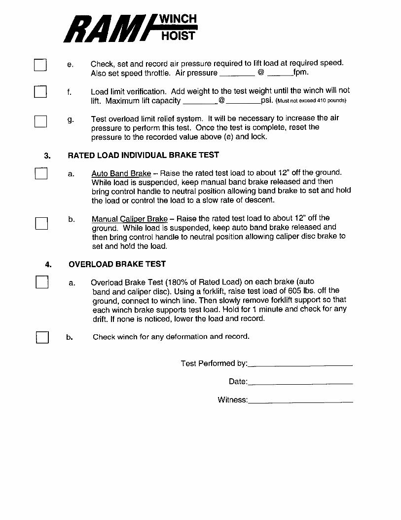
MAXIMUM RATED LOAD
CAPACITY 330 POUNDS (150Kg)


DO NOT ADD AN EXTERNAL LUBRICATOR TO THIS WINCH.
THERE IS ONE CONTAINED INSIDE THE CONTROL HOUSING.
Handle Position Emergency Air Supply
Handle Position Normal Air Supply
WARNING
CYLINDER IS SPRING LOADED
FILTER
DO NOT ADD OIL
LUBRICATOR USE 30wt OIL


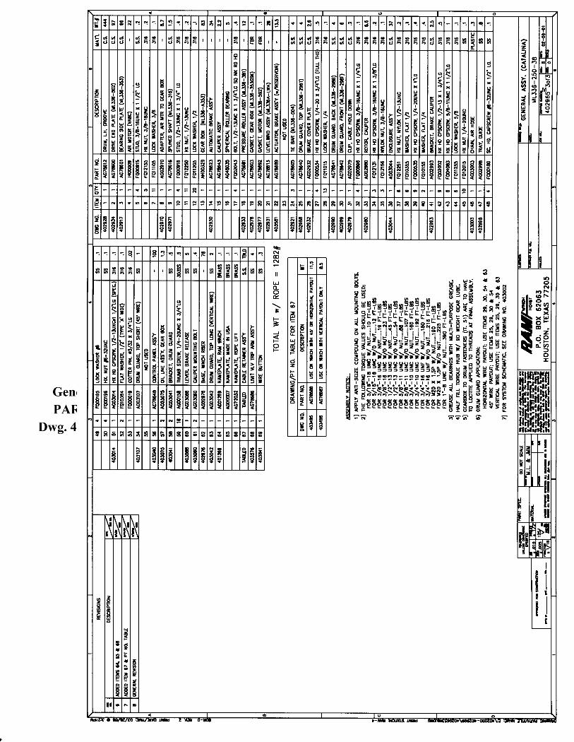
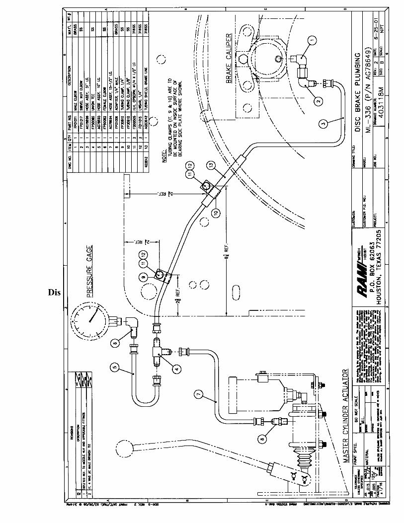
Check all the bolts or fasteners on the unit. It is possible for them to vibrate loose during transportation. Check to ensure that all the wrapping and packing material is removed prior to operation. Once the above items are completed, you may proceed to slowly open the air supply by opening the emergency stop valve (see drawing 403002M item “L”). Slowly open the valve and listen for any leaks. The slack limit switch may be open or exhausting when the pressure comes
up. If this happens, you will need to push the override button on the control panel. When the override is depressed, you will hear the poppet valve (see drawing 403002M item “K”) shift and you should then get pressure to the regulator.
If there is still escaping or exhausting air, check the emergency stop on the control panel. This is the red palm button. It should be in the “up” position. You may want to disconnect the slack limit trip arm during this phase of the
checkout. This will allow you to operate without holding down the override button.
This system must be reconnected after checkout and rigging of cable. Once the air supply is on, there should be a pressure reading on the gauge on the regulator. NOTE: This is the regulated pressure, not the main supply pressure. The winch controls are non-operable and must not be played with as
movement of the control valve will cause the brake to release and the winch drum will rotate.
The winch may now be operated to verify proper operation. If there is wire rope on the winch drum, care must be taken to prevent
damage to the rope, the winch or personnel. Operate the unit only a small amount in both directions to verify function. To operate, you will have to lift the center lock on the control valve handle and move the handle slowly off center in the direction of desired operation.
Be sure all personnel involved, or in the immediate vicinity, are aware of the
intended operation. Once the above is complete and the unit is operating properly, you may proceed to the next step. If the unit did not perform properly, consult RAM Winch and Hoist
Engineering Department for assistance.


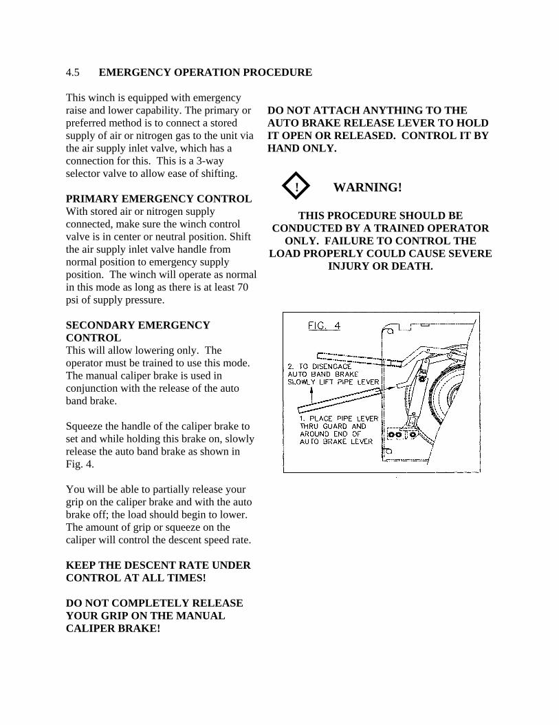
4.5 EMERGENCY OPERATION PROCEDURE This winch is equipped with emergency raise and lower capability. The primary or preferred method is to connect a stored supply of air or nitrogen gas to the unit via the air supply inlet valve, which has a connection for this. This is a 3-way selector valve to allow ease of shifting. PRIMARY EMERGENCY CONTROL With stored air or nitrogen supply connected, make sure the winch control valve is in center or neutral position. Shift the air supply inlet valve handle from normal position to emergency supply position. The winch will operate as normal in this mode as long as there is at least 70 psi of supply pressure. SECONDARY EMERGENCY CONTROL This will allow lowering only. The operator must be trained to use this mode. The manual caliper brake is used in conjunction with the release of the auto band brake. Squeeze the handle of the caliper brake to set and while holding this brake on, slowly release the auto band brake as shown in Fig. 4. You will be able to partially release your grip on the caliper brake and with the auto brake off; the load should begin to lower. The amount of grip or squeeze on the caliper will control the descent speed rate. KEEP THE DESCENT RATE UNDER CONTROL AT ALL TIMES! DO NOT COMPLETELY RELEASE YOUR GRIP ON THE MANUAL CALIPER BRAKE!
DO NOT ATTACH ANYTHING TO THE AUTO BRAKE RELEASE LEVER TO HOLD IT OPEN OR RELEASED. CONTROL IT BY HAND ONLY. ! WARNING!
THIS PROCEDURE SHOULD BE CONDUCTED BY A TRAINED OPERATOR
ONLY. FAILURE TO CONTROL THE LOAD PROPERLY COULD CAUSE SEVERE
INJURY OR DEATH.


RAM P/N AG04717 E-Stop Valve
System Pressure 0-150 psi (0-10 bar) Allowable Backpressure at exhaust port 0 Materials Valve body and caps: 316 Stainless steel (NACE Standard MR-01-75) Valve Seals: FKM (Fluorocarbon) O rings Screws: Stainless steel Lid Knob: Synthetic resin Porting Size and Flow Inlet, Outlet & exhaust ports: ¼” NPT Internal orifice: 3/8” (9.5 mm) ∅ Weight 0.1.0 lbs (.45 kg)


®
ACCESSORIES
4
Functional DescriptionShuttle Valves have a free moving shuttle that blocks one of twoinlet ports while the other inlet port is connected to the (com-mon) outlet port. When a pressure signal enters the portblocked by the shuttle, it will cause the shuttle to shift over toclose the opposite inlet port. The shuttle will stay there while theline or chamber connected to the outlet port is charged and/ordischarged and will only shift when pressure is applied to theinlet port it is blocking at that time.In logic terms a shuttle valve is an 'OR' - function.
PressuresPressure range– Pneumatic: 5 to 200 psi (0.35 to 14 bar)
Hydraulic: 5 to 500 psi (0.35 to 35 bar)
Symbol
MountingPreferably with the centerline of the two inlet ports horizontal.As shown in the drawing above.
Sizes/Connections/Types/Dimensions/Weights*Porting Product Number Dimensions in inch (mm) Flow Cv (Kv) Weights in lbs (kg)
'P' brass st. steel 'A' 'B' 'C' brass st. steel brass st. steel1/8 NPT SV-2 2.0 (51) 1.5 (38) 1.0 (25) 0.8 (12) 0.57 (0.26)1/4 NPT SV-3 SV-3-316 2.0 (51) 1.5 (38) 1.0 (25) 0.8 (12) 0.5 (7) 0.57 (0.26) 0.33 (0.15)3/8 NPT SV-4 2.5 (64) 1.9 (48) 1.3 (32) 1.6 (23) 1.10 (0.50)1/2 NPT SV-5 2.5 (64) 1.9 (48) 1.3 (32) 2.1 (30) 1.10 (0.50)3/4 NPT SV-6 3.5 (89) 2.8 (70) 1.5 (38) 6.5 (84) 2.16 (0.98)
* For Subplate Mounting Shuttle Valves Consult Factory†conforms to NACE standard MR-01-75
SHUTTLE VALVESa range of Shuttle Valves in different sizes, made from Brass or 316 Stainless Steel
General DescriptionVERSA Shuttle Valves are constructed of solid Brass or 316Stainless Steel, with resilient seals providing tight shut off.Shuttle valves are 3/2 valves, primarily used to charge and dis-charge a pressure line or chamber from two - or more -sources. A typical schematic is shown below:
MaterialsType: Brass Stainless Steel
Body: Brass 316 Stainless Steel†
Shuttle: Nylon(Zytel) 316 Stainless Steel†
Seals: NBR (Nitrile) FKM (Fluorocarbon) Screws: Plated Steel 316 Stainless Steel†
®
1 2 3
OUT
IN IN


RAM P/N AG00144 POPPET VALVE
Basic Size 1” Port Size 1” Operating Pressure psig (bar)
0-300 (0-20.7)
Pilot Pressure psig (bar) 30-300 (2.1 – 20.7) Weight lbs. (kg) 3.69 (1.68)


RAM P/N AG04714R MANUAL CONTROL VALVE 4 Way – 3 Position Manual Control
Valve Body Assembly 1 ¼” Ports
Hand Lever Assembly
Spring-Center Cap Assembly
SA-4702-72-12 For 1 ¼” Valves


RAM P/N AG00146 RAM P/N AG00152


RAM P/N AG00221 RELIEF VALVE
Body Material: Stainless Steel Connection 1 Size: ½” Connection 1 Type: Male NPT Taper Thread Connection 2 Size: ½” Connection 2 Type: Male NPT Taper Thread Cracking Pressure: 50 – 150 PSI (Adjustable) eClass: 37010801 Feature: 50 - 150 PSI (Adjustable) UNSPSC Code: 40141601


RAM P/N AG00180 Flow Control Valve


81-515-008 Hydraulic Apply Sliding Caliper Disc Brakes
Installation and Service Instructions
HYDRAULIC APPLYSliding Caliper Disc Brakes
When installing these brakes, it is ofutmost importance to maintain parallelism betweenmounting bolts and that caliper be centered evenly andsquarely over disc. This will prevent binding of caliperand ensure even lining to disc contact.
MOUNTING PROCEDURE1. Using Figure 1 and Table 2, determine “A”
dimension and locate caliper mounting holes.2. Distance from mounting surface to head of mount-
ing bolt is 82.6 mm (3.25") regardless of discthickness.
3. Mount brake on disc and bolt securely to vehicle ormachine using grade 5 or better mounting bolts orpins.
Disc Brake Linings do not contain asbestos. Brake lining compounds do, however,contain elements that may become airborne during the life of the lining. To prevent any healthproblems associated with lining dust, we suggest ventilators be installed as needed onenclosed or stationary equipment. A Material Safety Data Sheet is available upon request.
DISC DIA. “A” DIM.
152.4 mm (6") 85.9 mm (3.38")
203.2 mm (8") 111.3 mm (4.38")
254.0 mm (10") 136.7 mm (5.38")
304.8 mm (12") 162.1 mm (6.38")
355.6 mm (14") 187.5 mm (7.38")
406.4 mm (16") 212.9 mm (8.38")
457.2 mm (18") 238.3 mm (9.38")
508.0 mm (20") 263.7 mm (10.38")
DISC CENTERLINE TOMOUNTING HOLE DIMENSION
TABLE 2
For disc diameters greater than508.0 mm, add 9.7 mm (20", add .38")to disc radius to obtain “A” dimension.
millimetersinches

HYDRAULIC CONNECTION &ADJUSTMENT PROCEDURE(Refer to Figure 3)
Port Size: 1/8-27 NPTF1. Thread in brake module housing (2) until a total
clearance of approximately .30 mm (.012") isobtained between disc and linings. NOTE: Makesure piston (5) is bottomed out in brake modulehousing (2).
2. Back off brake module housing (2) as required toposition ports in vertical alignment.
3. Tighten set screw (8).4. Move bleeder screw (1) to higher of two ports for
ease of bleeding. Torque bleeder screw (1)16.3-19.0 N-m (12-14 lb-ft).
5. Install hydraulic line in lower port.6. Bleed system making sure all air is eliminated.
7. Apply rated hydraulic pressure and check for leaks.
CHANGE SEAL PROCEDURE(Refer to Figures 3 & 4)
See Table 1 for Repair Kit required for your brake.
1. Disconnect necessary fluid line from brake andremove caliper from vehicle or machine.
2. Remove set screw (8) from housing (11) and re-move brake module housing (2) from housing (11).
3. Place brake module housing (2) face down onbench, support brake module so piston (5) can beeased out of bore. This is accomplished by care-fully introducing low air pressure, .7-1.0 bar(10-15 psi), through the hydraulic line port.
4. Remove o-ring (3) and back-up ring (4) from piston(5). NOTE: Be careful not to scratch or marpiston.
5. Clean all parts thoroughly and lubricate all rubbercomponents from Repair Kit with clean type fluidused in the system.
6. Carefully install new o-ring (3) and new back-upring (4) on piston (5). Note order of back-up ringand o-ring.
7. Lubricate piston (5) with clean type system fluid andinstall in brake module housing (2). Note directionof piston and be sure it is bottomed out in brakemodule.
8. Thread brake module housing (2) into housing (11)until a total clearance of approximately .30 mm(.012") is obtained between disc and linings.
9. Back off brake module housing (2) as required toposition ports in vertical alignment.
10. Insert new nylon plug (7) into set screw (8) hole.Install nylon plug (7) even if originally not includedon your model.
11. Install and tighten set screw (8).12. Move bleeder screw (1) to higher of two ports for
ease of bleeding. Torque bleeder screw (1)16.3-19.0 N-m (12-14 lb-ft).
13. Install hydraulic line in lower port.14. Bleed system making sure all air is eliminated.
Apply hydraulic pressure and check for leaks.
CHANGE LINING PROCEDURE(Refer to Figure 3)
See Table 1 for Lining Kit required for your brake.Lining assemblies (10) can be replaced withoutremoving brake module housing (2).
1. Remove cap screw (6) and spring clip (9); allowlining assemblies (10) to drop out of housing (11).NOTE: On small diameter discs with largehubs, it may be necessary to remove onemounting bolt and swing housing aside to freelining assemblies. Earlier models used a com-pression spring which is not included in thelining kit.
2. Make sure piston (5) is bottomed out in brake mod-ule housing (2). Loosen set screw (8) and threadbrake module housing (2) out of housing (11) sopiston (5) is flush with housing (11).
3. Install new lining assemblies (10) in housing (11).4. Install new spring clip (9) and cap screw (6) and
torque 13.6-16.3 N-m (10-12 lb-ft). NOTE: If thelining kit does not include new spring clip (9)reinstall compression spring.
5. To continue, refer to HYDRAULIC CONNECTION &ADJUSTMENT PROCEDURE Section.
During the bleeding process for these brakes, hydraulic pressure should not exceed13.8 bar (200 psi).
Cap end of fluid line to prevent entry of dirt into hy-draulic system.
Do not use high pressure as it is dangerous and un-necessary. Use just enough air pressure to ease thepiston out of the bore. Do not blow piston out of thebore. If the piston is seized or cocked or does notcome out readily, release the air pressure and use asoft (brass) hammer to rap sharply on and around theend of the piston. Reapply air pressure to remove thepiston.