
WELDING GUIDE

Previous editions of the manual cease to be valid on publication of this edition of Böhler’smanual „Information for Welders“.
Particulars regarding the appearance and use of our products serve as information for theuser. Details of the mechanical properties always refer to the pure weld metal in accordancewith the applicable standards. The parent metal, the welding position and the welding parameters amongst other things affect the weld metal properties in the welded joint.
Express written agreement is required in each individual case as a guarantee of suitability for a specific purpose.
Edition 09/2006Technical Handbook of BÖHLER WELDING Products

Böhler Schweißtechnik Austria GmbHBöhler-Welding-St. 18605 Kapfenberg / AUSTRIA
+43 (0) 3862-301-0+43 (0) [email protected]
www.boehler-welding.comMember of the BÖHLER-UDDEHOLM Group
WELDING GUIDE

Preface
BÖHLER WELDING – Your Partner for Welding
“Our customers' problems are our problems too”is the basic principle at BÖHLER WELDING.
More than 80 years of experience gathered by the company in over 70 different countrieshas proved beyond doubt that, in practice, the quality of the welding is decisive. Whenextreme temperatures, maximum strength requirements, exceptional resistance tocorrosion or the highest possible working speed become the critical factors, adaptableknow-how is essential.
We pay close attention to all the issues relevant for successful welding - materials,application, welding additives - and cooperate with customers in developing the solutionmost favourable for them.
Nothing is too much trouble for us in our pursuit of optimal welding results for ourcustomers. Even in the Antarctic or the deserts of Africa, we provide our customers withproduct information, training courses and welding demonstrations.
When it comes to welding, only the best can satisfy us. That is why we collaborate inproduct development with universities and research institutes which have the necessaryequipment and personnel for performing the simulations and measurements we require(for example with scanning electron microscopes or high-speed cameras).
At BÖHLER WELDING it's results that count.
IV
Böhler Welding

Contents
V
ALPHABETICAL PRODUCT LIST . . . . . . . . . . . . . . . . . . . . . . . . . . . . . . . . . . . . . . . . . . . . . . VI
COMPARISON TABLE EN/AWS-CLASSIFICATION AND BÖHLER PRODUCTS . . . . . . . . XIV
GENERAL INFORMATION . . . . . . . . . . . . . . . . . . . . . . . . . . . . . . . . . . . . . . . . . . . . . . . . . . 1-1
PRODUCT INFORMATION . . . . . . . . . . . . . . . . . . . . . . . . . . . . . . . . . . . . . . . . . . . . . . . . . . 2-1
FILLER METALS
FOR MILD STEELS . . . . . . . . . . . . . . . . . . . . . . . . . . . . . . . . . . . . . . . . . . . . . . . . . . . . . . . 2-5
FILLER METALS
FOR PIPELINE WELDING . . . . . . . . . . . . . . . . . . . . . . . . . . . . . . . . . . . . . . . . . . . . . . . . 2-49
FILLER METALS FOR WEATHER-RESISTANT,
HIGH-STRENGTH AND CRYOGENIC STEELS . . . . . . . . . . . . . . . . . . . . . . . . . . . . . . . . 2-71
FILLER METALS FOR HIGH TEMPERATURE
AND CREEP RESISTANT STEELS. . . . . . . . . . . . . . . . . . . . . . . . . . . . . . . . . . . . . . . . . 2-101
FILLER METALS FOR STAINLESS
AND CORROSION RESISTANT STEELS . . . . . . . . . . . . . . . . . . . . . . . . . . . . . . . . . . . . 2-167
FILLER METALS FOR DISSIMILAR JOINTS
AND SPECIAL APPLICATIONS . . . . . . . . . . . . . . . . . . . . . . . . . . . . . . . . . . . . . . . . . . . . 2-263
FILLER METALS
FOR HEAT RESISTANT STEELS . . . . . . . . . . . . . . . . . . . . . . . . . . . . . . . . . . . . . . . . . . 2-295
NICKEL-BASE ALLOYS . . . . . . . . . . . . . . . . . . . . . . . . . . . . . . . . . . . . . . . . . . . . . . . . . 2-318
NON FERROUS ALLOYS . . . . . . . . . . . . . . . . . . . . . . . . . . . . . . . . . . . . . . . . . . . . . . . . 2-350
SUB-ARC
WELDING FLUXES . . . . . . . . . . . . . . . . . . . . . . . . . . . . . . . . . . . . . . . . . . . . . . . . . . . . . 2-355
SELECTION GUIDES FOR FILLER METALS AND WELDING PROCESSES . . . . . . . . . . 3-1
SELECTION GUIDE FOR THE OFFSHORE INDUSTRY . . . . . . . . . . . . . . . . . . . . . . . . . . 3-2
SELECTION GUIDE FOR THE CHEMICAL AND PETROCHEMICAL INDUSTRY. . . . . . . 3-4
SELECTION GUIDE FOR THERMAL POWER PLANTS . . . . . . . . . . . . . . . . . . . . . . . . . . 3-8
SELECTION GUIDE FOR HYDRO POWER . . . . . . . . . . . . . . . . . . . . . . . . . . . . . . . . . . . 3-10
SELECTION TABLES BASE MATERIAL ORIENTED SELECTION . . . . . . . . . . . . . . . . . 3-13
PROCESS BASED SELECTION OF CONSUMABLES. . . . . . . . . . . . . . . . . . . . . . . . . . . 3-33
MATERIAL BASED SELECTION OF CONSUMABLES. . . . . . . . . . . . . . . . . . . . . . . . . . . 3-45
WELDING TECHNOLOGY DETAILS . . . . . . . . . . . . . . . . . . . . . . . . . . . . . . . . . . . . . . . . . 3-87
EFFICIENCY AND CALCULATION GUIDE . . . . . . . . . . . . . . . . . . . . . . . . . . . . . . . . . . . . . 4-1
COMPARISON CHARTS AND OTHER TOOLS . . . . . . . . . . . . . . . . . . . . . . . . . . . . . . . . . . 5-1

B
F
F
F
F
F
FF
F
Böhler Welding
Alphabetical Product List
ÖHLER Type of filler metal Page
OX 2.5 Ni SMAW electrode, low-alloyed, cryogenic application 2-832.5 Ni-IG GTAW rod, low-alloyed, cryogenic application 2-872.5 Ni-IG GMAW solid wire, low-alloyed, cryogenic application 2-94
OX 20 MVW SMAW electrode, high-alloyed, creep resistant 2-12020 MVW-IG GTAW rod, high-alloyed, creep resistant 2-13620 MVW-UP/BB 24 SAW wire/flux-combination
high-alloyed, creep resistant 2-1603 NiCrMo 2.5-UP/BB 24 SAW wire/flux-combination, low-alloyed, high strength 2-973 NiMo 1-UP/BB 24 SAW wire/flux-combination, low-alloyed, high strength 2-96
OX A 7 SMAW electrode,high-alloyed, special applications 2-266
OX A 7-A SMAW electrode, high-alloyed, special applications 2-267A 7CN-IG GTAW rod, high-alloyed, special applications 2-276A 7-IG GMAW solid wire 2-279A 7-MC Metal cored wire, high-alloyed, special application 2-282A 7-FD GMAW flux cored wire, high-alloyed, Special applications 2-284A 7 PW-FD GMAW flux cored wire, high-alloyed, Special applications 2-285A 7CN-UP/BB 203 SAW wire/flux-combination
high-alloyed, special applications 2-290OX AM 400 SMAW electrode, high-alloyed, highly corrosion resistant 2-197
AM 400-IG GTAW rod, high-alloyed, highly corrosion resistant 2-212AM 400-IG GMAW solid wire, high-alloyed, highly corrosion resistant 2-230
OX ASN 5 SMAW electrode, high-alloyed, highly corrosion resistant 2-195OX ASN 5-A SMAW electrode, high-alloyed, highly corrosion resistant 2-196
ASN 5-IG GTAW rod, high-alloyed, highly corrosion resistant 2-211ASN 5-IG (Si) GMAW solid wire, high-alloyed,
highly corrosion resistant 2-229ASN 5-UP/BB 203 SAW wire/flux-combination
high-alloyed, highly corrosion resistant 2-259ASN 5 SY-UP/BB 202 SAW wire/flux-combination
high-alloyed, highly corrosion resistant 2-258BB 24 SAW flux, fluoride-basic type 2-357BB 25 SAW flux, fluoride-basic type 2-358BB 33 M SAW flux, aluminate-rutile-type 2-359BB 202 SAW flux, fluoride-basic type 2-361BB 203 SAW flux, fluoride-basic type 2-362BB 430 SAW flux, fluoride-basic type 2-363BB 444 SAW flux, fluoride-basic type 2-364BB 910 SAW flux, fluoride-basic type 2-365BF 16 SAW flux, manganese-silicate-type 2-360
OX BVD 85 SMAW electrode for vertical-down welding, basic, pipe welding 2-59
VI

VII
Böhler Welding
BÖHLER Type of filler metal Page
FOX BVD 90 SMAW electrode for vertical-down welding,basic coating, pipe welding 2-60
FOX BVD 100 SMAW electrode for vertical-down welding, basic coating, pipe welding, 2-61
FOX BVD 110 SMAW electrode for vertical-down welding,basic coating, pipe welding 2-62
FOX BVD 120 SMAW electrode for vertical-down welding,basic coating, pipe welding 2-63
FOX BVD RP SMAW electrode for vertical-down weldingbasic coating, pipe welding 2-58
BW VII Rod for gas welding, mild steel 2-45BW XII Rod for gas welding, mild steel 2-46
FOX C 9 MV SMAW electrode, high-alloyed, creep resistant 2-117C 9 MV-IG GTAW rod, high-alloyed, creep resistant 2-133C 9 MV-IG GMAW solid wire, high-alloyed, creep resistant 2-145C 9 MV-MC GMAW metal cored wire, high-alloyed, creep resistant 2-147C 9 MV-UP/BB 910 SAW wire/flux-combination, high-alloyed, creep resistant 2-158
FOX C 9 MVW SMAW electrode, high-alloyed, creep resistant 2-118C 9 MVW-IG GTAW rod, high-alloyed, creep resistant 2-134CAT 430 L Cb-IG GMAW solid wire, chemical resistant 2-218CAT 439 L Ti-IG GMAW solid wire, chemical resistant 2-219
FOX CEL SMAW electrode for vertical-down welding, cellulosic coated, pipe welding 2-52
FOX CEL+ SMAW electrode for vertical-down welding, cellulosic coated, pipe welding 2-53
FOX CEL 75 SMAW electrode for vertical-down welding, cellulosic coated, pipe welding 2-54
FOX CEL 85 SMAW electrode for vertical-down welding, cellulosic coated, pipe welding 2-56
FOX CEL 90 SMAW electrode for vertical-down welding, cellulosic coated, pipe welding 2-57
FOX CEL Mo SMAW electrode for vertical-down welding, cellulosic coated, pipe welding 2-55
FOX CM 2 Kb SMAW electrode, low-alloyed, high temperature 2-112CM 2-IG GTAW rod, low-alloyed, high temperature 2-128CM 2-IG GMAW solid wire, low-alloyed, high temperature 2-143CM 2-UP/BB 24 SAW wire/flux-combination, low-alloyed, high temperature 2-154
FOX CM 5 Kb SMAW electrode, low-alloyed, high temperature 2-115CM 5-IG GTAW rod, high-alloyed, high temperature 2-131CM 5-IG GMAW solid wire, high-alloyed, high temperature 2-144CM 5-UP/BB 24 SAW wire/flux-combination, high-alloyed, high temperature 2-157
FOX CM 9 Kb SMAW electrode, low-alloyed, high temperature 2-116CM 9-IG GTAW rod, high-alloyed, high temperature 2-132
FOX CN 13/4 SMAW electrode, high-alloyed, stainless 2-174FOX CN 13/4 SUPRA SMAW electrode, high-alloyed, stainless 2-175
CN 13/4-IG GTAW rod, high-alloyed, stainless 2-205

VIII
Böhler Welding
BÖHLER Type of filler metal Page
CN 13/4-IG GMAW solid wire, high-alloyed, stainless 2-220CN 13/4-MC Metal cored wire, high-alloyed, stainless 2-234CN 13/4-MC (F) Metal cored wire, high-alloyed, stainless 2-235CN 13/4-UP/BB 203 SAW wire/flux-combination, high-alloyed, stainless 2-252
FOX CN 16/13 SMAW electrode, high-alloyed, creep resistant 2-121CN 16/13-IG GTAW rod, high-alloyed, creep resistant 2-137
FOX CN 16/6 M-HD SMAW electrode, high-alloyed, stainless 2-179FOX CN 17/4 PH SMAW electrode, high-alloyed, stainless 2-180FOX CN 18/11 SMAW electrode, high-alloyed, creep resistant 2-122
CN 18/11-IG GTAW rod, high-alloyed, creep resistant 2-138CN 18/11-IG GMAW solid wire, high-alloyed, creep resistant 2-146CN 18/11-UP/BB 202 SAW wire/flux-combination,
high-alloyed, creep resistant 2-161FOX CN 19/9 M SMAW electrode, high-alloyed, special applications 2-268
CN 19/9 M-IG GTAW rod, high-alloyed, special applications 2-277CN 19/9 M-IG GMAW solid wire, high-alloyed,
special applications 2-280FOX CN 20/25 M SMAW electrode, high-alloyed, highly corrosion resistant 2-199FOX CN 20/25 M-A SMAW electrode, high-alloyed, highly corrosion resistant 2-200
CN 20/25 M-IG GTAW rod, high-alloyed, highly corrosion resistant 2-214CN 20/25 M-IG (Si) GMAW solid wire, high-alloyed,
highly corrosion resistant 2-231FOX CN 21/33 Mn SMAW electrode, high-alloyed, heat resistant 2-302
CN 21/33 Mn-IG GTAW rod, high-alloyed, heat resistant 2-308CN 21/33 Mn-IG GMAW solid wire, high-alloyed, heat resistant 2-314
FOX CN 22/9 N SMAW electrode, high-alloyed, highly corrosion resistant 2-202FOX CN 22/9 N-B SMAW electrode, high-alloyed, highly corrosion resistant 2-201
CN 22/9 N-FD GMAW flux cored wire, high-alloyed,highly corrosion resistant 2-250
CN 22/9 N-IG GTAW rod, high-alloyed, highly corrosion resistant 2-215CN 22/9 N-IG GMAW solid wire, high-alloyed,
highly corrosion resistant 2-232CN 22/9 N-UP/BB 202 SAW wire/flux-combination,
high-alloyed, highly corrosion resistant 2-260CN 22/9 PW-FD GMAW flux cored wire, high-alloyed,
highly corrosion resistant 2-251FOX CN 23/12-A SMAW electrode, high-alloyed, special applications 2-269
CN 23/12-MC Metal cored wire, high-alloyed, special application 2-283CN 23/12-FD GMAW flux cored wire, high-alloyed,
special applications 2-286CN 23/12 PW-FD GMAW flux cored wire, high-alloyed,
special applications 2-287CN 23/12-IG GTAW rod, high-alloyed, special applications 2-278CN 23/12-IG GMAW solid wire, high-alloyed,
special applications 2-281

IX
Böhler Welding
BÖHLER Type of filler metal Page
CN 23/12-UP/BB 202 SAW wire/flux-combinationhigh-alloyed, special applications 2-291
FOX CN 23/12 Mo-A SMAW electrode, high-alloyed, special applications 2-270CN 23/12 Mo-FD GMAW flux cored wire, high-alloyed,
special applications 2-288CN 23/12 Mo PW-FD GMAW flux cored wire, high-alloyed,
special applications 2-289FOX CN 24/13 SMAW electrode, high-alloyed, special applications 2-271FOX CN 24/13 Nb SMAW electrode, high-alloyed, special applications 2-272FOX CN 25/9 Cu T SMAW electrode, highly corrosion resistant 2-203
CN 25/9 Cu T-IG GTAW rod, highly corrosion resistant 2-216CN 25/9 Cu T-IG GMAW solid wire, highly corrosion resistant 2-233
FOX CN 25/35 Nb SMAW electrode, high-alloyed, heat resistant 2-303CN 25/35 Nb-IG GTAW rod, high-alloyed, heat resistant 2-309CN 25/35 Nb-IG GMAW solid wire, high-alloyed, heat resistant 2-315
FOX CN 29/9 SMAW electrode, high-alloyed, special applications 2-273FOX CN 29/9-A SMAW electrode, high-alloyed, special applications 2-274FOX CN 35/45 Nb SMAW electrode, high-alloyed, heat resistant 2-304
CN 35/45 Nb-IG GTAW rod, high-alloyed, heat resistant 2-310CN 35/45 Nb-IG GMAW solid wire, high-alloyed, heat resistant 2-316
FOX CuNi 30 Fe SMAW electrode, high-alloyed, copper-nickel 2-352CuNi 30 Fe-IG GTAW rod, high-alloyed, copper-nickel 2-353DCMS Gas welding rod, low-alloyed, high temperature 2-163
FOX DCMS Kb SMAW electrode, low-alloyed, high temperature 2-109FOX DCMS Ti SMAW electrode, low-alloyed, high temperature 2-108
DCMS-IG GTAW rod, low-alloyed, high temperature 2-126DCMS-IG GMAW solid wire, low-alloyed, high temperature 2-141
FOX DCMV SMAW electrode, low-alloyed, high temperature 2-110DMO Gas welding rod, low-alloyed, high temperature 2-162
FOX DMO Kb SMAW electrode, low-alloyed, high temperature 2-107FOX DMO Ti SMAW electrode, low-alloyed, high temperature 2-106
DMO-IG GTAW rod, low-alloyed, high strength 2-85DMO-IG GTAW rod, low-alloyed, high temperature 2-125DMO-IG GMAW solid wire, low-alloyed, high temperature 2-140
FOX DMV 83 Kb SMAW electrode, low-alloyed, high temperature 2-111DMV 83-IG GTAW rod, low-alloyed, high temperature 2-127DMV 83-IG GMAW solid wire, low-alloyed, high temperature 2-142
FOX E 308 H SMAW electrode, high-alloyed, creep resistant 2-123E 308 H-FD GMAW flux cored wire, high-alloyed, creep resistant 2-148E 308 H PW-FD GMAW flux cored wire, high-alloyed, creep resistant 2-149
FOX E 317 L SMAW electrode, high-alloyed, highly corrosion resistant 2-194E 317 L-FD GMAW flux cored wire, high-alloyed, highly corrosion resistant 2-248E 317 L PW-FD GMAW flux cored wire, high-alloyed, highly corrosion resistant 2-249
FOX E 347 H SMAW electrode, high-alloyed, creep resistant 2-124

X
Böhler Welding
BÖHLER Type of filler metal Page
FOX EAS 2 SMAW electrode, high-alloyed, chemical resistant 2-181FOX EAS 2-A SMAW electrode, high-alloyed, chemical resistant 2-182
EAS 2-MC Metal cored wire, high-alloyed, chemical resistant 2-236EAS 2-FD GMAW flux cored wire, high-alloyed, chemical resistant 2-238EAS 2 PW-FD GMAW flux cored wire, high-alloyed, chemical resistant 2-239EAS 2 PW-FD (LF) GMAW flux cored wire, high-alloyed, chemical resistant 2-240EAS 2-IG GTAW rod, high-alloyed, chemical resistant 2-206EAS 2-IG (Si) GMAW solid wire, high-alloyed, chemical resistant 2-225EAS 2-UP/BB 202 SAW wire/flux-combination
high-alloyed, chemical resistant 2-254FOX EAS 2-VD SMAW electrode, high-alloyed, chemical resistant 2-183FOX EAS 2 Si SMAW electrode, high-alloyed, highly corrosion resistant 2-193FOX EAS 4 M SMAW electrode, high-alloyed, chemical resistant 2-186FOX EAS 4 M (LF) SMAW electrode, high-alloyed, chemical resistant 2-187FOX EAS 4 M-A SMAW electrode, high-alloyed, chemical resistant 2-188
EAS 4 M-MC Metal cored wire, high-alloyed, chemical resistant 2-237EAS 4 M-FD GMAW flux cored wire, high-alloyed, chemical resistant 2-243EAS 4 PW-FD GMAW flux cored wire, high-alloyed, chemical resistant 2-244EAS 4 PW-FD (LF) GMAW flux cored wire, high-alloyed, chemical resistant 2-245EAS 4 M-IG GTAW rod, high-alloyed, chemical resistant 2-208EAS 4 M-IG (Si) GMAW solid wire, high-alloyed, chemical resistant 2-227
FOX EAS 4 M-TS SMAW electrode, high-alloyed, chemical resistant 2-190EAS 4 M-UP/BB 202 SAW wire/flux-combination
high-alloyed, chemical resistant 2-256FOX EAS 4 M-VD SMAW electrode, high-alloyed, chemical resistant 2-189
EASN 2 Si-IG GTAW rod, high-alloyed, highly corrosion resistant 2-210FOX EASN 25M SMAW electrode, highly corrosion resistant 2-198
EASN 25M-IG GTAW rod, highly corrosion resistant 2-213EMK 6 GTAW rod, unlegiert 2-27EMK 6 GMAW solid wire, mild steel 2-30EMK 7 GMAW solid wire, mild steel 2-31EMK 8 GMAW solid wire, mild steel 2-32EML 5 GTAW rod, mild steel 2-28EMS 2 CrMo/BB 24 SAW wire/flux-combination, low-alloyed, high temperature 2-152EMS 2 CrMo/BB 25 SAW wire/flux-combination, low-alloyed, high temperature 2-153EMS 2 Mo/BB 24 SAW wire/flux-combination, low-alloyed, high temperature 2-150EMS 2 Mo/BB 25 SAW wire/flux-combination, low-alloyed, high temperature 2-151EMS 2/BB 24 SAW wire/flux-combination, mild steel 2-37EMS 2/BB 25 SAW wire/flux-combination, mild steel 2-38EMS 2/BB 33 M SAW wire/flux-combination, mild steel 2-39EMS 2/BF 16 SAW wire/flux-combination, mild steel 2-40EMS 3/BB 24 SAW wire/flux-combination, mild steel 2-41EMS 3/BB 25 SAW wire/flux-combination, mild steel 2-42EMS 3/BB 33 M SAW wire/flux-combination, mild steel 2-43EMS 3/BF 16 SAW wire/flux-combination, mild steel 2-44

XI
Böhler Welding
BÖHLER Type of filler metal Page
ER 308 H-IG GTAW rod, high-alloyed, creep resistant 2-139ER 70 S-2 GTAW rod, mild steel 2-29 ER Ti 2-IG GTAW rod, Titanium 2-354
FOX ETI SMAW electrode, mild steel, rutile-coated 2-15FOX EV 47 SMAW electrode, mild steel, basic-coated 2-20FOX EV 50 SMAW electrode, mild steel, basic-coated 2-21FOX EV 50-A SMAW electrode, mild steel, basic-coated 2-22FOX EV 50-AK SMAW electrode, mild steel, basic-coated 2-23FOX EV 50-W SMAW electrode, mild steel, basic-coated 2-24FOX EV 55 SMAW electrode, mild steel, basic-coated 2-25FOX EV 60 SMAW electrode, low-alloyed, high strength 2-75FOX EV 60 PIPE SMAW electrode for vertical-up welding,
basic coating, pipe welding 2-65FOX EV 70 PIPE SMAW electrode for vertical-up welding,
basic coating, pipe welding 2-66FOX EV 63 SMAW electrode, low-alloyed, high strength 2-76FOX EV 65 SMAW electrode, low-alloyed, high strength 2-77FOX EV 70 SMAW electrode, low-alloyed, high strength 2-78FOX EV 70 Mo SMAW electrode, low-alloyed, high strength 2-79FOX EV 75 SMAW electrode, low-alloyed, high strength 2-81FOX EV 85 SMAW electrode, low-alloyed, high strength 2-82FOX EV 85-M SMAW electrode, high strength 2-84FOX EV 100 SMAW electrode, high strength 2-84FOX EV PIPE SMAW electrode for vertical-up welding,
basic coating, pipe welding 2-64FOX FA SMAW electrode, high-alloyed, heat resistant 2-297
FA-IG GTAW rod, high-alloyed, heat resistant 2-305FA-IG GMAW solid wire, high-alloyed, heat resistant 2-311
FOX FF SMAW electrode, high-alloyed, heat resistant 2-298FOX FF-A SMAW electrode, high-alloyed, heat resistant 2-299FOX FFB SMAW electrode, high-alloyed, heat resistant 2-300FOX FFB-A SMAW electrode, high-alloyed, heat resistant 2-301
FFB-IG GTAW rod, high-alloyed, heat resistant 2-307FFB-IG GMAW solid wire, high-alloyed, heat resistant 2-313FF-IG GTAW rod, high-alloyed, heat resistant 2-306FF-IG GMAW solid wire, high-alloyed, heat resistant 2-312
FOX HL 160 Ti SMAW electrode, mild steel, rutile coated, high efficiency 2-18FOX HL 180 Ti SMAW electrode, mild steel, rutile coated, high efficiency 2-19
HL 51-FD GMAW flux cored wire, mild steel, metal-cored 2-35HL 53-FD GMAW flux cored wire, mild steel, metal-cored 2-36I 52 Ni GTAW rod, pipe welding 2-86
FOX KE SMAW electrode, mild steel, rutile cellulose coated 2-12K Nova Ni GMAW solid wire, pipe welding 2-68K Nova Ni GMAW solid wire, high strength 2-89

BÖHLER Type of filler metal Page
KW 5 Nb-IG GMAW solid wire, high-alloyed, stainless 2-217FOX KW 10 SMAW electrode, high-alloyed, stainless 2-176
KW 10-IG GMAW solid wire, high-alloyed, stainless 2-221KWA-IG GMAW solid wire, high-alloyed, stainless 2-222
FOX MSU SMAW electrode, mild steel, rutile-cellulosic-coated 2-10Ni 2-UP/BB 24 SAW wire/flux-combination, low-alloyed, cryogenic application 2-98
FOX NIBAS 400 SMAW electrode, nickel base 2-329NIBAS 400-IG GTAW rod, nickel base 2-335NIBAS 400-IG GMAW solid wire, nickel base 2-341
FOX NIBAS 617 SMAW electrode, nickel base 2-327NIBAS 617-IG GTAW rod, nickel base 2-333NIBAS 617-IG GMAW solid wire, nickel base 2-339NIBAS 617-UP/BB 444 SAW wire/flux-combination, nickel base 2-347
FOX NIBAS 625 SMAW electrode, nickel base 2-323NIBAS 625-IG GTAW rod, nickel base 2-330NIBAS 625-IG GMAW solid wire, nickel base 2-336NIBAS 625-FD GMAW flux cored wire, nickel base 2-343NIBAS 625-UP/BB 444 SAW wire/flux-combination, nickel base 2-345
FOX NIBAS 60/15 SMAW electrode, nickel base 2-322FOX NIBAS 70/15 SMAW electrode, nickel base 2-324FOX NIBAS 70/20 SMAW electrode, nickel base 2-325
NIBAS 70/20-IG GTAW rod, nickel base 2-331NIBAS 70/20-IG GMAW solid wire, nickel base 2-337NIBAS 70/20-FD GMAW flux cored wire, nickel base 2-342NIBAS 70/20-UP/BB 444 SAW wire/flux-combination, nickel base 2-344
FOX NIBAS C 24 SMAW stick electrode, nickel base 2-326NIBAS C 24-IG GTAW rod, nickel base 2-332NIBAS C 24-IG GMAW solid wire, nickel base 2-338NIBAS C 24-UP/BB 444 SAW wire/flux-combination, nickel base 2-346
FOX NIBAS C 276 SMAW electrode, nickel base 2-328NIBAS C 276-IG GTAW rod, nickel base 2-334NIBAS C 276-IG GMAW solid wire, nickel base 2-340NIBAS C 276-UP/BB 444 SAW wire/flux-combination, nickel base 2-348
FOX NiCr 625 SMAW electrode, nickel base 2-323NiCr 625-IG GTAW rod, nickel base 2-330NiCr 625-IG GMAW solid wire, nickel base 2-336
FOX NiCr 70/15 SMAW electrode, nickel base 2-324FOX NiCr 70 Nb SMAW electrode, nickel base 2-325
NiCr 70 Nb-IG GTAW rod, nickel base 2-331NiCr 70 Nb-IG GMAW solid wire, nickel base 2-337NiCrMo 2.5-IG GMAW solid wire, low-alloyed, high strength 2-91NiCu 1-IG GMAW solid wire, low-alloyed, weather resistant 2-88
FOX NiCuCr SMAW electrode, low-alloyed, weather resistant 2-74FOX NiMo 100 SMAW electrode, low alloyed, high strenght 2-80
NiMo 1-IG GMAW solid wire for automatic welding, pipe welding 2-69NiMo 1-IG GMAW solid wire, low-alloyed, high strength 2-90
XII
Böhler Welding

BÖHLER Type of filler metal Page
FOX NUT SMAW electrode, gouging electrode 2-26FOX OHV SMAW electrode, unlegiert, rutil cellulose umhüllt 2-11FOX P 23 SMAW electrode, low-alloyed, high temperature 2-113
P 23-IG GTAW rod, low-alloyed, high temperature 2-129P 23-UP/BB 430 SAW wire/flux-combination, low-alloyed, high temperature 2-155
FOX P 24 SMAW electrode, low-alloyed, high temperature 2-114P 24-IG GTAW rod, low-alloyed, high temperature 2-130P 24-UP/BB 430 SAW wire/flux-combination, low-alloyed, high temperature 2-156
FOX P92 SMAW electrode, high-alloyed, creep resistant 2-119P92-IG GTAW rod, high-alloyed, creep resistant 2-135P92-UP/BB 910 SAW wire/flux-combination,
high-alloyed, creep resistant 2-159FOX RDA SMAW electrode, high-alloyed, special applications 2-275FOX SAS 2 SMAW electrode, high-alloyed, chemical resistant 2-184FOX SAS 2-A SMAW electrode, high-alloyed, chemical resistant 2-185
SAS 2-IG GTAW rod, high-alloyed, chemical resistant 2-207SAS 2-IG (Si) GMAW solid wire, high-alloyed,
chemical resistant 2-226SAS 2-FD GMAW flux cored wire, high-alloyed, chemical resistant 2-241SAS 2 PW-FD GMAW flux cored wire, high-alloyed, chemical resistant 2-242SAS 2-UP/BB 202 SAW wire/flux-combination
high-alloyed, chemical resistant 2-255FOX SAS 4 SMAW electrode, high-alloyed, chemical resistant 2-191FOX SAS 4-A SMAW electrode, high-alloyed, chemical resistant 2-192
SAS 4-IG GTAW rod, high-alloyed, chemical resistant 2-209SAS 4-IG (Si) GMAW solid wire, high-alloyed, chemical resistant 2-228SAS 4-FD GMAW flux cored wire, high-alloyed, chemical resistant 2-246SAS 4 PW-FD GMAW flux cored wire, high-alloyed, chemical resistant 2-247SAS 4-UP/BB 202 SAW wire/flux-combination,
high-alloyed, chemical resistant 2-257SG3-P GMAW solid wire for automatic welding, pipe welding 2-67
FOX SKWA SMAW electrode, high-alloyed, stainless 2-177SKWA-IG GMAW solid wire, high-alloyed, stainless 2-223
FOX SKWAM SMAW electrode, high-alloyed, stainless 2-178SKWAM-IG GMAW solid wire, high-alloyed, stainless 2-224SKWAM-UP/BB 203 SAW wire/flux-combination, high-alloyed, stainless 2-253
FOX SPE SMAW electrode, mild steel, rutile-basic-coated 2-16FOX SPEM SMAW electrode, mild steel, rutile-basic-coated 2-17FOX SUM SMAW electrode, mild steel, rutile-basic-coated 2-13FOX SUS SMAW electrode, mild steel, rutile-basic-coated 2-14
Ti 52-FD GMAW flux cored wire, mild steel, rutile typ 2-33Ti 52 W-FD GMAW flux cored wire, mild steel, rutile typ 2-34Ti 60-FD GMAW flux cored wire, low-alloyed, rutile typ 2-95X 70-IG GMAW solid wire, low-alloyed, high strength 2-92X 90-IG GMAW solid wire, low-alloyed, high strength 2-93
XIII
Böhler Welding

XIV
Comparison Table EN-Classification and BÖHLER products
Classification-based or Approval-based Selection
EN-Classification Böhler
E 13 4 B 4 2 FOX CN 13/4 SUPRAE 13 4 B 6 2 FOX CN 13/4E 13 B 2 2 FOX KW 10E 17 B 2 2 FOX SKWAE 18 16 5 N L B 2 2 FOX ASN 5E 18 16 5 N L R 3 2 FOX ASN 5-AE 18 8 Mn B 2 2 FOX A 7E Z 18 9 MnMo R 3 2 FOX A 7-AE 19 12 3 L R 1 2 FOX EAS 4 M-TSE 19 12 3 L R 1 5 FOX EAS 4 M-VDE 19 12 3 L R 3 2 FOX EAS 4 M-AE 19 12 3 LB 2 2 FOX EAS 4 ME 19 12 3 Nb B 2 2 FOX SAS 4E 19 12 3 Nb R 3 2 FOX SAS 4-AE 19 9 B 4 2 H5 FOX CN 18/11E 19 9 H R 4 2 H5 FOX E 308 HE 19 9 L B 2 2 FOX EAS 2E 19 9 L R 1 5 FOX EAS 2-VDE 19 9 L R 3 2 FOX EAS 2-AE 19 9 Nb B 2 2 FOX SAS 2
FOX E 347 H E 19 9 Nb R 3 2 FOX SAS 2-AE 20 10 3 R 3 2 FOX CN 19/9 ME 20 25 5 Cu N L B 2 2 FOX CN 20/25 ME 20 25 5 Cu N L R 3 2 FOX CN 20/25 M-AE 22 12 B 2 2 FOX FFE 22 12 R 3 2 FOX FF-AE 22 9 3 L B 2 2 FOX CN 22/9 N-BE 22 9 3 L R 3 2 FOX CN 22/9 NE 24 12 B 2 2 FOX CN 24/13E 23 12 Nb B 2 2 FOX CN 24/13 NbE 23 12 2 L R 3 2 FOX CN 23/12 Mo-AE 23 12 L R 3 2 FOX CN 23/12-AE 25 94 N L B 2 2 FOX CN 25/9 CuTE 25 20 B 2 2 FOX FFBE 25 20 R 3 2 FOX FFB-AE 25 4 B 2 2 FOX FAE 29 9 R 1 2 FOX CN 29/9E 29 9 R 3 2 FOX CN 29/9-AE 38 0 RC 11 FOX MSU, FOX OHV
FOX KEE 38 0 RR 12 FOX SUME 38 0 RR 54 FOX HL 160 TiE 38 0 RR 74 FOX HL 180 TiE 38 2 RB 12 FOX SPE
FOX SPEME 38 3 C 21 FOX CELE 38 2 C 21 FOX CEL+E 38 4 B 42 H5 FOX EV 47E 42 0 RR 12 FOX SUS, FOX ETIE 42 3 B 12 H10 FOX EV 50-AE 42 3 C 25 FOX CEL 75
EN-Classification Böhler
E 42 3 Mo C 25 FOX CEL MoE 42 3 RB 32 H10 FOX EV 50-AKE 42 5 B 12 H5 FOX EV 50-WE 42 4 B 12 H5 FOX EV PIPEE 42 5 B 42 H5 FOX EV 50E 46 3 B 41 FOX BVD RPE 46 4 Z (NiCrCu) B 42 FOX NiCuCrE 46 4 1 Ni C 2 5 FOX CEL 85E 46 5 1Ni B 45 FOX BVD 85E 46 5 B 12 H5 FOX EV 55E 46 6 1Ni B 42 H5 FOX EV 60E 46 8 2Ni B 4 2 H5 FOX 2.5 NiE 50 3 1Ni C 25 FOX CEL 90E 50 4 B 42 H5 FOX EV 63E 50 4 1Ni B12 H5 FOX EV 60 PIPEE 55 3 MnMo B T 4 2 H10 FOX EV 70 MoE 55 4 Z(Mn2NiMo) B12 H5 FOX EV 70 PIPE E 55 5 Z2Ni B 4 5 FOX BVD 90E 55 6 1NiMo B 4 2 H5 FOX EV 65
FOX EV 70E 62 4 Mn1NiMo B42 H5 FOX NiMo 100E 62 5 Z2Ni B 4 5 FOX BVD 100E 62 6 Mn2NiCrMo B42 H5 FOX EV 75E 69 3 Mn2NiMo B 4 5 FOX BVD 110
FOX BVD 120E 69 6 Mn2NiCrMo B42 H5 FOX EV 85E CrMo1 B 4 2 H5 FOX DCMS KbE CrMo1 R 1 2 FOX DCMS TiE CrMo2 B 4 2 H5 FOX CM 2 KbE CrMo5 B 4 2 H5 FOX CM 5 KbE CrMo9 B 4 2 H5 FOX CM 9 KbE CrMo91 B 4 2 H5 FOX C 9 MVE CrMoWV12 B 4 2 H5 FOX 20 MVWE Mo B 4 2 H5 FOX DMO KbE Mo R 1 2 FOX DMO TiE MoV B 4 2 H5 FOX DMV 83 KbE Ni 66 20 FOX NIBAS 60/15E Ni 40 60 FOX NIBAS 400E Ni 66 17 FOX NIBAS 617E Ni 60 59 FOX NIBAS C 24E Ni 62 76 FOX NIBAS C 276E Z 16 13 Nb B 4 2 H5 FOX CN 16/13E Z 16 6 Mo B 6 2 H5 FOX CN 16/6 M-HDE Z 17 4 Cu B 4 3 H5 FOX CN 17/4 PHE Z 17 Mo B 2 2 FOX SKWAME Z 19 14 Si B 2 2 FOX EAS 2 SiE Z 21 33 B 4 2 FOX CN 21/33 MnE Z 22 18 4 L B 2 2 FOX AM 400E Z 25 22 2 NL B 2 2 FOX EASN 25 ME Z 25 35 Nb B 6 2 FOX CN 25/35 NbE Z 35 45 Nb 6 2 FOX CN 35/45 NbE Z CrMoV1 B 4 2 H5 FOX DCMV

XV
Selection Guide
EN-Classification Böhler
E Z CrMoWV911 B 4 2 H5 FOX C 9 MVWE Z CrMoWVNb 9 0.5 2 B42H5 FOX P 92E Z CrMoVNb B 21 B42 H5 FOX P 24E Z CrWV21.5 B42 H5 FOX P 23E Ni 61 82 FOX NIBAS 70/15
FOX NiCr 70/15E Ni 60 82 FOX NIBAS 70/20
NIBAS 70/20-FDFOX NiCr 70 Nb
E Ni 66 25 FOX NIBAS 625NIBAS 625-FDFOX NiCr 625
G 13 4 CN 13/4-IGG 17 KWA-IGG 18 8 Mn A 7-IGG 19 12 3 L Si EAS 4 M-IG (Si)G 19 12 3 NbSi SAS 4-IG (Si)G 19 9 H CN 18/11-IGG 19 9 L Si EAS 2-IG (Si)G 19 9 NbSi SAS 2-IG (Si)G 20 10 3 CN 19/9 M-IGG 22 12 H FF-IGG 22 9 3 NL CN 22/9 N-IGG 23 12 L CN 23/12-IGG 25 94 NL CN 25/9 CuT-IGG 25 20 Mn FFB-IGG 25 4 FA-IGG 3 Ni 1 K Nova NiG 3 Si 1 EMK 6G 0 NiCu 1-IGG 4 Si 1 EMK 7, EMK 8G 42 4 M G0 NiCu 1-IGG 4 Si 1 EMK 7, EMK 8G 46 6 C G2 Ni2 2.5 Ni-IGG 46 8 M G2 Ni2 2.5 Ni-IGG 42 4 C G0 G 4 Si 1 SG 3-PG 46 5 M G0 G 4 Si 1 SG 3-PG 55 4 C Mn3Ni1Mo NiMo 1-IGG 55 6 M Mn3Ni1Mo NiMo 1-IGG 69 5 M Mn3CrNi1CrMo X 70-IGG 69 4 C Mn3CrNi2.5CrMo NiCrMo 2.5-IGG 69 6 M Mn3CrNi2.5CrMo NiCrMo 2.5-IGG 89 6 M Mn4Ni2CrMo X 90-IGG CrMo1Si DCMS-IGG CrMo2 Si CM 2-IGG CrMo5 Si CM 5-IGG CrMo91 C 9 MV-IGG MoSi DMO-IGG MoV Si DMV 83-IGG Z 13 KW 10-IGG Z 13 Nb L KW 5 Nb-IGG Z 17 Mo SKWAM-IGG Z 17 Ti SKWA-IGG Z 18 Nb L CAT 430 L Cb-IGG Z 18 Ti L CAT 439 L Ti-IGG Z 18 16 5 NL ASN 5-IG (Si)G Z 20 25 5 Cu NL CN 20/25 M-IG (Si)
EN-Classification Böhler
G Z 21 33 Nb CN 21/33 Mn-IGG Z 22 17 8 4 NL AM 400-IGG Z 25 35 Nb CN 25/35 Nb-IGG Z 35 45 Nb H CN 35/45 Nb-IGO I BW VIIO III BW XIIO IV DMOO V DCMSS 13 4 / SA FB 2 DC CN 13/4-UP/BB 203S 17 / SA FB 2 SKWA-UP/BB 202S 17 Mo H SKWAM-UP/BB 203S 18 16 5 NL / SA FB 2 ASN 5-UP/BB 203S 18 8 Mn / SA FB 2 A 7CN-UP/BB 203S 19 9 H / SA FB 2 CN 18/11-UP/BB 202S 19 9 L / SA FB 2 DC EAS 2-UP/BB 202S 19 9 Nb / SA FB 2 SAS 2-UP/BB 202S 22 9 3NL/SA FB 2 DC CN 22/9 N-UP/BB 202S 38 0 MS S2 EMS 2/BF 16S 38 0 MS S3 EMS 3/BF 16S 38 6 FB S2 EMS 2/BB 24S 42 3 FB S3 EMS 3/BB 25S 42 4 FB S2 EMS 2/BB 25S 42 4 FB S3 EMS 3/BB 24S 46 0 AR S2 EMS 2/BB 33 MS 46 3 FB S2Mo EMS 2 Mo/BB 25S 46 4 FB S2Mo EMS 2 Mo/BB 24S 46 6 FB S2Ni2 Ni 2-UP/BB 24S 50 0 AR S3 EMS 3/BB 33 MS 50 4 FB S3Ni1Mo 3 NiMo 1-UP/BB24S 69 6 FB SZ3Ni2CrMo 3 NiCrMo 2.5-UP/BB 24S CrMo1 / SA FB 1 EMS 2 CrMo/BB 24S CrMo1 /SA FB 1 EMS 2 CrMo/BB 25S CrMo2 / SA FB 1 CM 2-UP/BB 24S CrMo5 / SA FB 1 CM 5-UP/BB 24S CrMo91 / SA FB 2 C 9 MV-UP/BB 910S Z CrMoWVNb 9 0.5 2/SA FB 2 P 92-UP/BB 910S Z CrWV 2 P 23-UP
P 24-UPS19 12 3L / SA FB 2 DC EAS 4 M-UP/BB 202S19 12 3Nb/SA FB 2 DC SAS 4-UP/BB 202S 23 12 L / SA FB 2 DC CN 23/12-UP/BB 202SA AR 1 97 AC BB 33 MSA FB 1 55 AC BB 430SA FB 1 65 DC H5 BB 24SA FB 1 68 AC H5 BB 25SA FB 2 BB 444SA FB 2 55 DC BB 910SA FB 2 DC BB 202SA FB 2 DC BB 203SCrMoWV12/SA FB 2 20 MVW-UP/BB 24SF MS 1 78 AC BF 16S Ni 60 82 NIBAS 70/20-IG
NiCr 70 Nb-IGNIBAS 70/20-UP
S Ni 40 60 NIBAS 400-IGS Ni 66 17 NIBAS 617-IG
NIBAS 617-UPS Ni 60 59 NIBAS C24-IG
NIBAS C24-UP

XVI
Classification-based or Approval-based Selection
EN-Classification Böhler
S Ni 6276 NIBAS C276-IGNIBAS C276-UP
Ni 66 25 NIBAS 625-IGNiCr 625-IGNIBAS 625-UP
T 13 4 MM 2 CN 13/4 MCT 13 4 MM 2 CN 13/4 MC (F)T 18 8 Mn MM 1 A 7-MCT 18 8 Mn R C 3 A 7-FDT 18 8 Mn R M 3 A 7-FDT 18 8 Mn P C 2 A 7 PW-FDT 18 8 Mn P M 2 A 7 PW-FDT 19 12 3 L MM 1 EAS 4 M-MCT 19 12 3 L P C 1 EAS 4 PW-FDT 19 12 3 L P M 1 EAS 4 PW-FDT 19 12 3 L R C 3 EAS 4 M-FDT 19 12 3 L R M 3 EAS 4 M-FDT 19 12 3 Nb P C 1 SAS 4 PW-FDT 19 12 3 Nb P M 1 SAS 4 PW-FDT 19 12 3 Nb R C 3 SAS 4-FDT 19 12 3 Nb R M 3 SAS 4-FDTZ 19 13 4 L R M 3 E 317L-FDTZ 19 13 4 L R C 3 E 317L-FDTZ 19 13 4 L P M 1 E 317L PW-FDTZ 19 13 4 L P C 1 E 317L PW-FDT 19 9 L MM 1 EAS 2 MCT 19 9 L P C 1 EAS 2 PW-FDT 19 9 L P M 1 EAS 2 PW-FDT 19 9 L R C 3 EAS 2-FDT 19 9 L R M 3 EAS 2-FDT 19 9 Nb P C 1 SAS 2 PW-FDT 19 9 Nb P M 1 SAS 2 PW-FDT 19 9 Nb R C 3 SAS 2-FDT 19 9 Nb R M 3 SAS 2-FDT 22 9 3 NL P C 1 CN 22/9 PW-FDT 22 9 3 NL P M 1 CN 22/9 PW-FDT 22 9 3 NL R C 3 CN 22/9 N-FDT 22 9 3 NL R M 3 CN 22/9 N-FDT 23 12 L MM 1 CN 23/12 MCT 23 12 2 L P C 1 CN 23/12 Mo PW-FDT 23 12 2 L P M 1 CN 23/12 Mo PW-FDT 23 12 2 L R C 3 CN 23/12 Mo-FDT 23 12 2 L R M 3 CN 23/12 Mo-FDT 23 12 L P M 1 CN 23/12 PW-FDT 23 12 L P C 1 CN 23/12 PW-FDT 23 12 L R M 3 CN 23/12-FDT 23 12 L R C 3 CN 23/12-FDT CrMo 9 1 C 9 MV-MC
EN-Classification Böhler
T 42 2 P C 1 H5 Ti 52-FDTi 52 W-FD
T 42 5 Z MM 2 H5 HL 53-FDT 46 2 P M 1 H10 Ti 52-FDT 46 4 P M 1 H 10 Ti 52 W-FDT 50 6 1 Ni P M 1 H5 Ti 60-FDT 46 4 M M 2 H5 HL 51-FDT Z 19 9 H P C 1 E 308 H PW-FDT Z 19 9 H P M 1 E 308 H PW-FDT Z 19 9 H R C 3 E 308 H-FDT Z 19 9 H R M 3 E 308 H-FDW 13 4 CN 13/4-IGW 18 8 Mn A 7CN-IGW 19 12 3 L EAS 4 M-IGW 19 12 3 Nb SAS 4-IGW 19 9 H CN 18/11-IG
ER 308 H-IGW 19 9 L EAS 2-IGW 19 9 Nb SAS 2-IGW 20 10 3 CN 19/9 M-IGW 22 12 H FF-IGW 22 9 3 NL CN 22/9 N-IGW 23 12 L CN 23/12-IGW 25 4 FA-IGW 25 9 4 NL CN 25/9 CuT-IGW 25 20 Mn FFB-IGW 25 2 2 2 NL EASN 25 M-IGW 3 Si 1 EMK 6W 2 Mo DMO-IGW 2 Si EML 5W 2 Ni 2 2.5 Ni-IGW 3 Ni 1 I 52 NiW CrMo1 Si DCMS-IGW CrMo2 Si CM 2-IGW CrMo5 Si CM 5-IGW CrMo9 Si CM 9-IGW CrMo91 C 9 MV-IGW CrMoWV12 20 MVW-IGW Mo Si DMO-IGW MoV Si DMV 83-IGW Z 16 13 Nb CN 16/13-IGW Z 18 16 5 NL ASN 5-IGW Z 19 13 Si NL EASN 2 Si-IGW Z 20 25 5 Cu NL CN 20/25 M-IGW Z 21 33 Nb CN 21/33 Mn-IGW Z 22 17 8 4 NL AM 400-IGW Z 25 35 Nb CN 25/35 Nb-IGW Z 35 45 Nb CN 35/45 Nb-IGW Z CrMoVW 911 C 9 MVW-IGW Z CrMoWVNb 9 0.5 2 P 92-IG

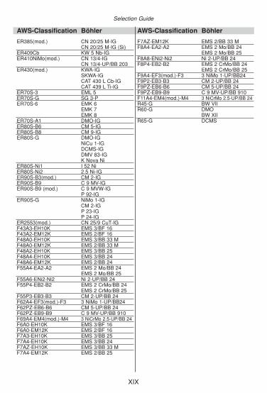
Comparison Table AWS-Classification andBÖHLER product
Selection Guide
AWS-Classification Böhler
E10018-G FOX BVD 100FOX EV 75
E11018-G FOX BVD 110FOX EV 85
E2209-15 FOX CN 22/9 N-BE2209-17 FOX CN 22/9 NE2553-15(mod.) FOX CN 25/9CuTE307-15(mod.) FOX A 7E307-16(mod.) FOX A 7-AE307T0-G A 7-FDE307T1-G A7 PW-FDE308L-15 FOX EAS 2E308L-17 FOX EAS 2-A
FOX EAS 2-VDE308-15 FOX CN 18/11E309Cb-15 FOX CN 24/13 NbE308H-16 FOX E 308 HE309L-15 FOX CN 24/13E309L-17 FOX CN 23/12-AE309MoL-17(mod.) FOX CN 23/12 Mo-AE309-15(mod.) FOX FFE309-17 FOX FF-AE310-15(mod.) FOX FFBE310-16 FOX FFB-AE312-16(mod.) FOX CN 29/9E312-17(mod.) FOX CN 29/9-AE316 L-15 FOX EAS 4 ME316 L-16 (mod.) FOX EAS 4 M-TSE316 L-17 FOX EAS 4 M-A
FOX EAS 4 M-VDE317L-17 FOX E 317 LE317LN-15(mod.) FOX ASN 5E317LN-17(mod.) FOX ASN 5-AE318-15 FOX SAS 4E318-17 FOX SAS 4-AE347-15 FOX SAS 2
FOX E 347 HE347-17 FOX SAS 2-AE 385-15 (mod.) FOX CN 20/25 ME 385-17 (mod.) FOX CN 20/25 M-AE 410 NiMo-15 FOX CN 13/4 SUPRAE 410 NiMo-25 FOX CN 13/4E 410-15 (mod.) FOX KW 10E 430-15 FOX SKWAE 6010 FOX CEL
FOX CEL+E 6013 FOX MSU
FOX OHV
AWS-Classification Böhler
E 6013 FOX KEFOX SUMFOX SUSFOX ETI
E6013(mod.) FOX SPEFOX SPEM
E7010-A1 FOX CEL MoE7010-P1 FOX CEL 75E7016 FOX EV 50-AE7016-1H4R FOX EV 50-WE7016-1H4R FOX EV PIPE
FOX EV 47E7018(mod.) FOX EV 50-AKE7018-1H4R FOX EV 50
FOX EV 55E7018-A1 FOX DMO KbE7024 FOX HL 180 TiE7024-1 FOX HL 160 TiE8010-P1 FOX CEL 85E8013-G FOX DCMS TiE8016-GH4R FOX EV 60 PIPEE8018-B2H4R FOX DCMS KbE8018-B6H4R FOX CM 5 KbE8018-B8 FOX CM 9 KbE8018-C1H4R FOX 2.5 NiE8018-C3H4R FOX EV 60E8018-D1H4R(mod.) FOX EV 65E8018-G FOX BVD RP
FOX BVD 85E8018-GH4R FOX EV 63
FOX EV 65E8018-W2H4R FOX NiCuCrE9015-B9 FOX C 9 MVE9015-B9(mod.) FOX C 9 MVW
FOX P 92E9016-GH4R FOX EV 70 PIPEE9018-B3H4R FOX CM 2 KbE9018-D1H4R(mod.) FOX EV 70
FOX EV 70 MoE9018-G FOX BVD 9
FOX DCMVFOX DMV 83 KbFOX EV 70 MoFOX P 23FOX P 24
E9010-G FOX CEL 90E9018-GH4R FOX EV 70E10018-G FOX NiMo 100E10018-GH4R FOX EV 75
XVII

Classification-based or Approval-based Selection
AWS-Classification Böhler
E10018-MH4R(mod.) FOX EV 75E11018-GH4R FOX EV 85EC90S-B9 C 9 MV-MCEC307(mod.) A 7-MCEC308L EAS 2-MCEC309L CN 23/12-MCEC316L EAS 4 M-MCEC410NiMo(mod.) CN 13/4-MCEC410NiMo(mod.) CN 13/4-MC (F)ECuNi FOX CuNi 30 FeENiCrFe-3 FOX NIBAS 70/15
FOX NiCr 70/15ENiCrFe-3(mod.) FOX NIBAS 70/20
FOX NiCr 70 NbENiCrCoMo1 FOX NIBAS 617ENiCrMo-3 FOX NIBAS 625
FOX NiCr 625ENiCrMo-4 FOX NIBAS C 276ENiCrMo-6 FOX NIBAS 60/15ENiCrMo-13 FOX NIBAS C 24ENiCr-3T0-4 NIBAS 70/20-FDENiCu-7 FOX NIBAS 400E16-8-2-25(mod.) FOX CN 16/6 M-HDE2209T0-1 CN 22/9 N-FDE2209T0-4 CN 22/9 N-FDE2209T1-1 CN 22/9 PW-FDE2209T1-4 CN 22/9 PW-FDE308HT0-1 E 308 H-FDE308HT0-4 E 308 H-FDE308HT1-1 E 308 H PW-FDE308HT1-4 E 308 H PW-FDE308LT0-1 EAS 2-FDE308LT0-4 EAS 2-FDE308LT1-1 EAS 2 PW-FDE308LT1-4 EAS 2 PW-FDE308Mo-17(mod.) FOX CN 19/9 ME309LMoT0-1 CN 23/12 Mo-FDE309LMoT0-4 CN 23/12 Mo-FDE309LMoT1-1 CN 23/12 Mo PW-FDE309LMoT1-4 CN 23/12 Mo PW-FDE309LT0-1 CN 23/12-FDE309LT0-4 CN 23/12-FDE309LT1-4 CN 23/12 PW-FDE309LT1-1 CN 23/12 PW-FDE316LT0-1 EAS 4 M-FDE316LT0-4 EAS 4 M-FDE316LT1-1 EAS 4 PW-FDE316LT1-4 EAS 4 PW-FDE317LT0-4 E 317L-FDE317LT1-4(1) E 317L PW-FDE318 T1-4 SAS 4 PW-FDE318 T1-1 SAS 4 PW-FDE318 T0-1 SAS 4-FDE318 T0-4 SAS 4-FDE347LT1-1 SAS 2 PW-FDE347LT1-4 SAS 2 PW-FDE347LT0-1 SAS 2-FDE347LT0-4 SAS 2-FDEC410NiMo(mod.) CN 13/4 MC
AWS-Classification Böhler
EG P 23-UPP 24-UP
E630-15(mod.) FOX CN 17/4 PHE70C-6MH4 HL 53-FDE70C-6MH4 HL 51-FDE71T-1H4 Ti 52-FDE71T-1MJH8ER80S-Ni1 Ti 52 W-FDE81T1-Ni1MH8 Ti 60-FDERCuNi CuNi 30 Fe-IGERNiCr-3 NIBAS 70/20-IG
NiCr 70 Nb-IGNIBAS 70/20-UP
ERNiCrCoMo1 NIBAS 617-IGNIBAS 617-UP
ERNiCrMo-3 NIBAS 625-IGNIBAS 625-UP
ERNiCrMo-3 NiCr 625-IGERNiCrMo4 NIBAS C 276-IG
NIBAS C 276-UPERTi2 ER Ti 2-IGERNiCrMo13 NIBAS 24-IG
NIBAS 24-UPER110S-G NiCrMo 2.5-IG
X 70-IGERNiCu7 NIBAS 400-IGER120S-G X 90-IGER19-10H CN 18/11-IGER2209 CN 22/9 N-IG
CN 22/9 N-UP/BB 202ER2553(mod.) CN 25/9 CuT-IGER307(mod.) A 7CN-IG
A 7-IGA 7CN-UP/BB 203
ER308LSi EAS 2-IG (Si)ER308H ER 308 H-IGER308L EAS 2-IG
EAS 2-UP/BB 202ER308Mo(mod.) CN 19/9 M-IGER309(mod.) FF-IGER309L CN 23/12-IG
CN 23/12-UP/BB 202ER310(mod.) FFB-IGER316LSi EAS 4 M-IG (Si)ER316L EAS 4 M-IG
EAS 4 M-UP/BB 202ER317L ASN 5 S4-UP/BB 202ER317LN(mod.) ASN 5-IG (Si)
ASN 5-IGASN 5-UP/BB 203
ER318 SAS 4-IGSAS 4-UP/BB 202
ER318(mod.) SAS 4-IG (Si)ER347Si SAS 2-IG (Si)ER347 SAS 2-UP
SAS 2-IGER70S-2 ER 70 S-2E12018-G FOX BVD 120
XVIII
XIX
Selection Guide
AWS-Classification Böhler
ER385(mod.) CN 20/25 M-IGCN 20/25 M-IG (Si)
ER409Cb KW 5 Nb-IGER410NiMo(mod.) CN 13/4-IG
CN 13/4-UP/BB 203ER430(mod.) KWA-IG
SKWA-IGCAT 430 L Cb-IGCAT 439 L Ti-IG
ER70S-3 EML 5ER70S-G SG 3-PER70S-6 EMK 6
EMK 7EMK 8
ER70S-A1 DMO-IGER80S-B6 CM 5-IGER80S-B8 CM 9-IGER80S-G DMO-IG
NiCu 1-IGDCMS-IGDMV 83-IGK Nova Ni
ER80S-Ni1 I 52 NiER80S-Ni2 2.5 Ni-IGER90S-B3(mod.) CM 2-IGER90S-B9 C 9 MV-IGER90S-B9 (mod.) C 9 MVW-IG
P 92-IGER90S-G NiMo 1-IG
CM 2-IGP 23-IGP 24-IG
ER2553(mod.) CN 25/9 CuT-IGF43A3-EH10K EMS 3/BF 16F43A2-EM12K EMS 2/BF 16F48A0-EH10K EMS 3/BB 33 MF48A0-EM12K EMS 2/BB 33 MF48A2-EH10K EMS 3/BB 25F48A4-EH10K EMS 3/BB 24F48A6-EM12K EMS 2/BB 24F55A4-EA2-A2 EMS 2 Mo/BB 24
EMS 2 Mo/BB 25F55A6-ENi2-Ni2 Ni 2-UP/BB 24F55P4-EB2-B2 EMS 2 CrMo/BB 24
EMS 2 CrMo/BB 25F55P3-EB3-B3 CM 2-UP/BB 24F62A4-EF3(mod.)-F3 3 NiMo 1-UP/BB24F62PZ-EB6-B6 CM 5-UP/BB 24F62PZ-EB9-B9 C 9 MV-UP/BB 910F69A4-EM4(mod.)-M4 3 NiCrMo 2.5-UP/BB 24F6A0-EH10K EMS 3/BF 16F6A0-EM12K EMS 2/BF 16F7A3-EH10K EMS 3/BB 25F7A4-EH10K EMS 3/BB 24F7AZ-EH10K EMS 3/BB 33 MF7A4-EM12K EMS 2/BB 25
AWS-Classification Böhler
F7AZ-EM12K EMS 2/BB 33 MF8A4-EA2-A2 EMS 2 Mo/BB 24
EMS 2 Mo/BB 25F8A8-ENi2-Ni2 Ni 2-UP/BB 24F8P4-EB2-B2 EMS 2 CrMo/BB 24
EMS 2 CrMo/BB 25F9A4-EF3(mod.)-F3 3 NiMo 1-UP/BB24F9P2-EB3-B3 CM 2-UP/BB 24F9PZ-EB6-B6 CM 5-UP/BB 24F9PZ-EB9-B9 C 9 MV-UP/BB 910F11A4-EM4(mod.)-M4 3 NiCrMo 2.5-UP/BB 24R45-G BW VIIR60-G DMO
BW XIIR65-G DCMS
1-1
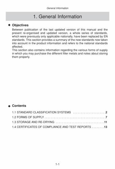
1. General Information
ObjectivesBetween publication of the last updated version of this manual and thepresent re-organised and updated version, a whole series of standards,which were previously only applicable nationally, have been replaced by ENstandards. This section provides a summary of the new standards now takeninto account in the product information and refers to the national standardsaffected. This section also contains information regarding the various forms of supplyin which you may purchase the different filler metals and notes about storingthem properly.
Contents
1.1 STANDARD CLASSIFICATION SYSTEMS . . . . . . . . . . . . . . . . . . . . .2
1.2 FORMS OF SUPPLY . . . . . . . . . . . . . . . . . . . . . . . . . . . . . . . . . . . . . . .7
1.3 STORAGE AND RE-DRYING . . . . . . . . . . . . . . . . . . . . . . . . . . . . . . .11
1.4 CERTIFICATES OF COMPLIANCE AND TEST REPORTS . . . . . . . .13
◆
◆
General Information

1-2
General Information
1.1. Standard Classification SystemsClassification System according European Standard
European Standards for Filler Metals - Overview
EN-Standard Official Title of Filler Metal Standard
EN 440 Wire electrodes and deposits for gas shielded metal arc welding of non alloy and fine grain steels. Classification.
EN 2560-A Covered electrodes for manual metalarc welding of non alloy and fine grain steels. Classification.
EN 756 Solid wires, solid wire-flux and tubular cored electrode-flux combinations for submerged arc welding of non alloy and fine grain steels. Classification.
EN 757 Welding consumables. Covered electrodes for manual metal arcwelding of high strength steels. Classification.
EN 758 Tubular cored electrodes for metal arc weldingwith or without a gas shield of non-alloy and fine grain steels. Classification.
EN 760 Fluxes for submerged arc welding. Classification.
EN 1599 Covered electrodes for manual metal arc welding ofcreep resisting steels. Classification.
EN 1600 Covered electrodes for manual metal arc welding of stainless and heat resisting steels. Classification.
EN 1668 Welding consumables of rods, wires and deposits for tungsten inert gas welding of non alloy and fine grain steels.
EN 12070 Welding consumables wire electrodes, wires and rods for arc welding of creep-resisting steels. Classification.
EN 12071 Tubular cored electrodes for gas shielded metal arc weldingof creep-resisting steels. Classification.
EN 12072 Welding consumables wire electrodes, wires and rods for arc welding of stainless and heat resisting steels. Classification.
EN 12073 Tubular cored electrodes for metal arc welding with or without a gas shield of stainless and heat resisting steels. Classification.
EN 12534 Welding consumables wire electrodes, wires, rods and deposits for gas shielded metal arc welding of high strength steels. Classification.
EN 12535 Tubular cored electrodes for gas shielded metal arc welding ofhigh strength steels. Classification.
EN 12536 Rods for gas welding of non alloy and creep resisting steels. Classification.
The listed European Standards became or will become transformed into national standards.From this the contents of an European Standard are equal to a national standard.Note: „tubular cored electrodes“ are equal to the generally used term „flux cored wires“

1-3
Standard Classification Systems
Classification system for EN/ISO 2560-A and EN 757, partially for EN 1599 and EN 1600 for example FOX EV 70 Mo
short related EN- key description standards
welding process, type of product
designator characterising the welding process 2560-A, 757, 1599 or the type of product 1600
mechanical properties, alloying type
key number indicating the mechanical properties of the all-weld metal 2560-A, 757
key number indicating the lowest temperature with an defined average impact work 2560-A, 757
designator for the alloying type of the weld deposit 2560-A, 757, 15991600
coating and heat treatment
descriptor showing the type of coating 2560-A, 757, 1599 1600
designator indicating a heat treatment of the weld deposit 757
supplemental designations
designator indicating deposition rate and 2560-A, 757, 1599 type of current to be used 1600
key number for the welding positions 2560-A, 757, 1599 1600
diffusible hydrogen designator indicating the maximumdiffusible hydrogen level obtained with the product 2560-A, 757, 1599
E
55
3
MnMo
B
T
4
2
H10
1-4
General Information
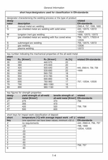
short keys/designators used for classification in EN-standards
designator characterising the welding process or the type of productdesig- related nator description EN-standardsE manual metal arc welding 2560-A, 757, 1599, 1600G gas shielded metal arc welding with solid wires 440, 12070, 12072
12534W tungsten inert gas welding 1668, 12070, 12072T gas shielded metal arc welding with flux cored wires 758, 12071, 17633-A
12535S submerged arc welding 756, 12070, 12072O gas welding 12536P plasma welding 12072
key number indicating the mechanical properties of the all-weld metalshortkey ReL [N/mm2] Rm [N/mm2] A5 [%] related EN-standards35 355 440-570 2238 380 470-600 2042 420 500-640 20 440, 2560-A, 756, 75846 460 530-680 20 166850 500 560-720 1855 550 610-780 1862 620 690-890 1869 690 760-960 17 757, 12534, 1253579 790 880-1080 1689 890 980-1180 15
key figures for strength propertiesdesig- yield strength of all-weld tensile strength of related nator metal [N/mm2] all-weld metal [N/mm2] EN-standards2T 275 370 7563T 355 4704T 420 520 756, 7585T 500 600
short keys for impact work classification of depositshort temperature [°C] with average impact work >47 J related key (one specimen can have lower values, minimum >32 J) EN-standardsZ no requirements 440, 2560-A, 756, 757 A +20 788, 1668 0 0 12534, 125352 -203 -304 -405 -506 -607 -70 756, 7578 -80
1-5
Standard Classification Systems
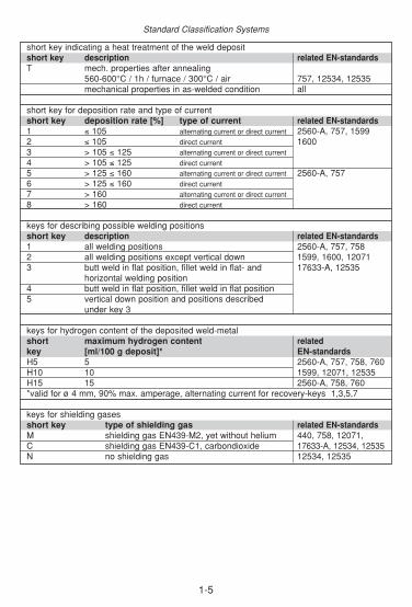
short key indicating a heat treatment of the weld depositshort key description related EN-standardsT mech. properties after annealing
560-600°C / 1h / furnace / 300°C / air 757, 12534, 12535mechanical properties in as-welded condition all
short key for deposition rate and type of current short key deposition rate [%] type of current related EN-standards1 ≤ 105 alternating current or direct current 2560-A, 757, 1599 2 ≤ 105 direct current 16003 > 105 ≤ 125 alternating current or direct current4 > 105 ≤ 125 direct current5 > 125 ≤ 160 alternating current or direct current 2560-A, 7576 > 125 ≤ 160 direct current7 > 160 alternating current or direct current8 > 160 direct current
keys for describing possible welding positionsshort key description related EN-standards1 all welding positions 2560-A, 757, 758 2 all welding positions except vertical down 1599, 1600, 120713 butt weld in flat position, fillet weld in flat- and 17633-A, 12535
horizontal welding position4 butt weld in flat position, fillet weld in flat position 5 vertical down position and positions described
under key 3
keys for hydrogen content of the deposited weld-metalshort maximum hydrogen content relatedkey [ml/100 g deposit]* EN-standardsH5 5 2560-A, 757, 758, 760H10 10 1599, 12071, 12535H15 15 2560-A, 758, 760*valid for ø 4 mm, 90% max. amperage, alternating current for recovery-keys 1,3,5,7
keys for shielding gasesshort key type of shielding gas related EN-standardsM shielding gas EN439-M2, yet without helium 440, 758, 12071, C shielding gas EN439-C1, carbondioxide 17633-A, 12534, 12535N no shielding gas 12534, 12535

1-6
General Information
designator for coating typesdesignator type of coating related EN-standardsA acid coated 2560-A, 757, 1599C cellulosic coated 1600R rutile coatedRR thick rutile coatedRC rutile-cellulosic- coatedRA rutile-acid- coatedRB rutile-basic- coatedB basic coated
designators for sub-arc welding flux typesdesignator type of sub-arc welding flux related EN-standardsMS mangenese-silicate 756, 760CS calcium-silicateZS zirkonium-silicateRS rutile-silicateAR aluminium-rutileAB aluminium-basicAS aluminium-silicateAF aluminium-fluoride-basicFB fluoride-basicZ other types
keys for types of fillings in flux-cored wiresshort type and relatedkey properties EN-standardsR rutile, slow freezing slag, 758, 12071, 17633-A
shielding gas necessary 12535P rutile, fast freezing slag, shielding gas necessary 758B basic, shielding gas necessary 758, 12071, 17633-A
12535M metal powder, shielding gas necessary 758, 17633-AV rutile or basic/fluoride, shielding gas not necessaryW basic/fluoride, slow freezing slag,
shielding gas not necessaryY basic/fluoride, fast freezing slag,
shielding gas not necessaryS other typesZ other types 12071, 17633-A, 12535U without shielding gas 12535
A description of all keys defining the chemical composition is not part of this handbook.

1-7
1.2. Forms of Supply
ENISO 544 outside Inside external kgdiameter d1 diameter d2 width b wire
B 300 300 180 103 15/16/18
wire basket spool
Forms of Supply for GMAW Wires
wire net weight per spool for: non-alloy/low-alloy solid wires 18 kghigh-alloy solid wires and flux-cored wires 15 kgnon-alloy/low-alloy flux-cored wires 16 kg
Forms of Supply
Forms of Supply for Stick ElectrodesNon-alloy and low-alloy stick electrodes: 4 boxes per master carton
Cellulose and basic-coated vertical-down electrodes: In hermetically sealed TINS approx. 9.5 kg
net weight.2 tins per master carton.
High-alloy stick electrodes: With the exception of a few products, Böhler high-alloy stick electrodes are supplied in hermetically-sealed TINS with net contents of approx. 3.5 to 5 kg.3 tins per master carton.
The advantages of this packaging, which is impermeable to water vapour, are: • The electrode coating remains absolutely dry.• The electrodes can always be welded with the best possible usability properties
without re-drying.• There is absolutely no starting porosity.• The ability to store and transport the electrodes is not dependent on climate.• The tin itself is made of tinplate and is ecologically disposable.
Vacuum-packed Böhler stick electrodes, which are available at additional cost in all alloy variants on request, offer similar advantages.
Forms of Supply for TIG and Gas Welding RodsNon-alloy and low-alloy welding rods are supplied in 25 kg packs. High-alloy welding rods in 20 kg packs (4 x 5 kg units per pack)
d2
d1b

1-8
ECO-DRUM ÖKO-MULTI
ideal bulk pack for 250 kg of non-, low-and high-alloy welding wires in roboticquality; outstanding for welding robotsand other mechanised stations
for 250 kg of non-, low- and high-alloyedwelding wires in robotic quality; ECO-MULTI's are reuseable and will reducewaste disposal expense and/or storagespace as empty units can be packed
Drum heads in two different design can be ordered seperately
ENISO 544 outside spindle external tapped hole kgdia- hole width dia- distance wiremeter meter from centerd1 d3 b d4 e1
S 100 100 16,5 45 – – 1,0
S 200 200 50,5 55 10 44,5 5
S 300 300 51,5 103 10 44,5 15
plastic spool
810
520
800
530
d1
d3
b

1-9
BÖHLER outside inside width kgdia- dia- b wiremeter d1 meter d2
B 390 280 70 26I 430 310 100 30S 390 300 70 23PRG 80* 390 310 80 21PRG 100* 430 310 100 25
* coiled on a cardboard former
coils
Forms of Supply for Sub-arc Wires
bulk spool (steel)
BÖHLER outside inside spindle width kgdia- dia- hole dia- wiremeter d1 meter d2 meter d3 outside b1 inside b2
GS 760 760 430 41 310 270 300Non returnable
d3
d2
d1b1
d1 d2
b

1-10
General Information
Individual Forms of SupplyPlease enquire if you have specific delivery requests for wire electrodes or other filler metals.
Forms of Supply for Sub-arc Welding Fluxesin bags of 25 kg (BF 16, BB 24, BB 25, BB 33 M)in tins of 30 kg (BB 202, BB 203, BB 910)
650
300
900
tension ring
top cover
Paper DrumIdeal bulk pack up to 400 kg for un-, low andhigh alloyed welding wire in robotic quality.Outstanding for welding robots and other mechanized welding stations.
BÖHLER outside inside external kgdia- dia- width wiremeter d1 meter d2 b
K 415-100 415 300 100 25
K 435-70* 435 300 70 25
* K 435 is the standard spool for stainless steel sub-arc wires
d2
d1b
wire basket

1-11
Storage and Re-drying
1.3. Storage and Re-dryingStorage of Stick ElectrodesOn principle coated stick electrodes should be stored in their original packaging until used. Ifpossible the packs of electrodes should be taken out of storage in the sequence in which theywere received in the warehouse.
The stick electrodes must be stored in dry rooms to protect them against damage caused bymoisture. As a result the electrode warehouse should be protected against the elements andeasily ventilated. Ceiling, floor and walls must be dry and there should be no uncovered waterin the room. The room must be fitted out with pallets or shelves since storage directly on thefloor or against the walls is not recommended.
Opened packs of electrodes should also be stored in dry and, if necessary, heated rooms sothat there is no likelihood of the temperature dropping below the dew point.
Re-drying of Stick electrodesWhere electrodes have become damp it is recommended that re-drying is carried out imme-diately prior to welding in accordance with the temperature details specified in the followingtables. Welding straight from the dryer is recommended in all cases so as to comply with thelowest possible water contents.
stick electrodes for … type of coating re-drying re-drying re-dryingrecommended temperature in °C time in hours
non and low alloy A, AR, C, RC, no -- --steels R, RR, RB
B yes 300 – 350 2 – 10high strength fine grained steels B yes 300 – 350 2 – 10creep resistant steels R no -- --
RB, B yes 300 – 350 2 – 10corrosion resistant and R yes 120 – 200 2 – 10scaling resistant steels RB, B no -- --soft-martensitic steels B yes 300 – 350 2 – 10duplex-steels RB yes 250 – 300 2 – 10nickel alloys all if necessary 120 – 300 2 – 10
Re-drying temperature and re-drying time can be found at the labels of our products.
The following procedure is worthwhile for re-drying electrodes:• The electrodes should be placed into a pre-heated oven (approx. 80-100°C) with
no more than three layers on top of each other.• The recommended temperature should be maintained for approx. 2 hours after the electro-
des have heated up. In the case of re-drying temperatures above 250°C the temperature should be increased slowly (approx. 150°C/hour) to the recommended temperature.
• A total drying time of 10 hours (= sum total of the times for the individual re-drying processes) should not be exceeded. This maximum time must also be observed if re-drying takes place in several cycles.
• The temperature should be decreased to 70 to 90°C before removing the electrodes from the furnace.
Electrodes that have been in direct contact with water, grease or oil should not be used forwelding fabrication. In this case even re-drying does not provide an adequate solution with theresult that they should only be used for low-quality work.
Coated stick electrodes that are supplied in tins require no re-drying if they are placeddirectly into the dryer and are used straight from there.

1-12
General Information
It may still be worthwhile to re-dry in individual cases even in the case of stick electrodes forwhich there is no re-drying recommendation given in the table above. This may be appropriatein the case of incorrect storage or as a result of other conditions leading to high watercontents. The high water content can usually be recognised from the welding behaviour whichexhibits increased spattering or pore formation. In these cases the stick electrodes may bere-dried for approx. one hour at 100-120°C unless specified otherwise by the manufacturer.This recommendation does not apply to cellulose-coated stick electrodes which may not bere-dried at all.The temperature for temporary storage in an oven following re-drying should be 120-200°C(maximum 30 days total holding time), for storage in dryers 100-200°C (10 days maximumtotal holding time).
Storage of Flux-cored WiresThe danger of moisture absorption is not the same for flux-cored wires as for stick electrodes.The flux core is largely shielded from the ambient atmosphere by the outer metal.Nevertheless, the „low-hydrogen” character of a flux-cored wire may be impaired by extremecontact with damp air. This may happen for example if they are stored overnight without pro-tection in an atmosphere with high humidity.Flux-cored wires should be stored in warehouses with controlled temperature and humidityconditions. We recommend dry, if necessary, heated rooms so that there is no likelihood ofthe temperature dropping below the dew point. The aim is not more than 60 % relative humi-dity and at least 15°C.If stored at below 10°C there is a danger that condensation will form on the surface of the wirewhen the package is opened in a heated room. This can lead to pore and gas impressions onthe weld at the beginning of welding. Welding should only be performed using acclimatised wires. The coil with the remaining wire should be removed from the unit when welding is finished andreplaced in its original packaging taking care to re-seal the compound aluminium foil aseffectively as possible. A tin such as those used for the delivery of BÖHLER flux powders forhigh-alloy steels may also be used for temporary storage.
Re-drying of Flux-cored WiresRe-drying is usually possible in principle and should be carried out over 24 hours at approx.150°C.
Storage and Re-drying of Sub-arc Welding FluxesIt is recommended that flux powders are stored under the driest possible conditions and attemperatures which are as even as possible to keep water absorption to a minimum duringstorage. Powders stored in this manner may generally be kept for up to three years. Powderfrom containers damaged during transport must be used or re-packed immediately. Fluoride-basic flux powders should be re-dried prior to use to ensure crack-free welding. It ispossible to dispense with re-drying for flux powders that are taken directly from sealed, air-tight, undamaged sheet metal containers (BB 202, BB 203, BB 910).
flux production type of flux re-drying re-drying re-dryingrecommended temperature in °C time in hours
agglomerated FB yes ca. 350 2 - 10AR yes ca. 300 2 - 10
fused MS yes ca. 150 2 - 500
The drying temperatures and times given in the previous table should be considered asgeneral reference values. Re-drying may take place several times within the sum total ofhours specified. After re-drying, flux powder that is not used immediately must be storedtemporarily at increased temperature or in sealed airtight containers. The temporary storagetemperature should be around 150°C and storage itself should not exceed 30 days.
The ovens used for re-drying should not permit localised overheating of the powder and mustbe adequately ventilated. In the case of stationary drying the layer of powder should notexceed 50 mm.
1-13
Certificates of Compliance and Test Reports
1.4. Cerfificates of Complianceand Test Reports
General NotesWorks certificates or acceptance test certificates to EN 10204 can be issued for everydelivery on request. It is also possible to receive test reports in accordance with AWS A5.01.Basically speaking all types of certificates should be requested on placing the order.It is imperative that the scope of testing is specified in the case of acceptance test certificatesEN 10204-3.1 und test reports. Subsequent issuing of a 3.1 certificate or a test report with ascope of testing which deviates from schedules F and H always entails increased costs foradministration and expenditure. It is no longer possible to issue certificates at a later date if aseries has already come out of production and has been processed in its entirety.
Works Certificates acc. EN 10204-2.2These certificates are product-related, i.e. a separate certificate is issued for each series orbatch number. This certificate records all the values arising during the current in-processinspection that are relevant to the certificate. This means that for all low, medium andhigh-alloy stick electrodes and flux cored wires the respective actual values from the currentquality test are inserted for the chemical analysis whilst for non-alloy electrodes and flux coredwires to some extent only statistical values based on non-specific testing are shown. The heat analyses of the associated batches are specified for all solid wires and rods. With the exception of the submerged-arc wires and flux powder, mechanical property data areshown on the works certificates for all products. The values specified are guaranteedtolerance limits (minimum and/or maximum depending on the standard requirement) andcorrespond to the minimum properties guaranteed for the product in this manual.
Acceptance Test Certificates acc. EN 10204-3.1 and 3.2Acceptance test certificates 3.1 or 3.2 will also be issued on request. In order to do this testsmust be performed on the delivery or on the production unit with which the delivery is asso-ciated. Since this is a certificate concerning a delivery-related test according to informationsupplied by the purchaser, it is imperative that the scope of testing should be made clear atthe time of ordering or even at the enquiry stage. The costs arising will be charged accordingto expenditure.
Test Reports acc. AWS A5.01A test report should be requested if a certificate of the product’s conformity with the AWS isrequired for a customer’s project. The test report includes as standard a confirmation ofconformity for compliance with the applicable AWS standard or the reference to this AWSstandard contained in ASME II, Part C.The test report will correspond to "Schedule F" of AWS A5.01 if no further elements arespecified by the customer. This test report is comparable with a works certificate "2.2" asregards content. The scope of testing required must be disclosed at the point of ordering for all otherschedules. In this case costs will be charged according to expenditure.

1-14
General Information
Notes
2-1
◆
◆
2. Product Information
ÜbersichtInformation über Werkstoffe zählt zu den wesentlichen Voraussetzungen füreine zielführende Auswahl von Schweißzusätzen. Der beschränkte Umfangdieses Handbuches erlaubt zwar nicht eine vollständige Angabe aller rele-vanten Eigenschaften, doch soll zumindest ein Überblick über die gültigenEN- und die auslaufenden bzw. noch gültigen DIN-Bezeichnungen und diechemische Zusammensetzung aller im europäischen Raum mit Werkstoff-nummern genormten Werkstoffe gegeben werden.
Contents
2.1 GENERAL REMARKS . . . . . . . . . . . . . . . . . . . . . . . . . . . . . . . . . . . .2
2.2 FILLER METALS FOR MILD STEELS . . . . . . . . . . . . . . . . . . . . . . . .5
2.3 FILLER METALS FOR PIPELINE WELDING . . . . . . . . . . . . . . . . . .49
2.4 FILLER METALS FOR WEATHER-RESISTANT,
HIGH-STRENGTH AND CRYOGENIC STEELS . . . . . . . . . . . . . . .71
2.5 FILLER METALS FOR HIGH TEMPERATURE AND
CREEP RESISTANT STEELS . . . . . . . . . . . . . . . . . . . . . . . . . . . .101
2.6 FILLER METALS FOR STAINLESS AND
CORROSION RESISTANT STEELS . . . . . . . . . . . . . . . . . . . . . . .167
2.7 FILLER METALS FOR DISSIMILAR JOINTS AND
SPECIAL APPLICATIONS . . . . . . . . . . . . . . . . . . . . . . . . . . . . . . .263
2.8 FILLER METALS FOR HEAT RESISTANT STEELS . . . . . . . . . . .295
2.9 NICKEL-BASE . . . . . . . . . . . . . . . . . . . . . . . . . . . . . . . . . . . . . . . . .319
2.10 NON FERROUS ALLOYS . . . . . . . . . . . . . . . . . . . . . . . . . . . . . . . .350
2.11 SUB-ARC WELDING FLUXES . . . . . . . . . . . . . . . . . . . . . . . . . . . .355

2.1. General remarks
The product information on the following pages has been kept standard for all filler metalsproduced by BÖHLER Welding. Unlike previous versions of this manual, all the data for aproduct is summarised on one page. The intention is to make it easier for you, the reader, tohave a complete overview of a product.
Again, to make it easier to navigate, the header section of each page of data contains a refe-rence to the sub-section, product form and/or a colour coding. Numbering in the footersection refers only to the section itself. Details of the version are intended to facilitatearchiving if individual pages of the manual are to be used as reference in other documents.
Each of the following eight sections is sub-divided in the following order according to productforms where available: Covered Electrodes, TIG rods, solid wires, flux cored wires, sub-arc wire/flux combinations and gas welding rods.
Each product is identified by its trade name and a product group. The product description contains some alterations compared with the most recent editions ofthe manual. Amongst other things the classification according to standard was consistentlyswitched over to valid editions of the EN or AWS standard. To make the changeover easier,national standards such as DIN, NF and BS are still shown but are provided with a notereferring to substitution by the EN.
The changeover was also carried out consistently with regard to the information about parentmetals. If you encounter problems with the new material designations, Section 1 provides abrief overview of the systematic way in which materials are classified according to EN 10027and ECISS IC10.
The section „Description“ on each page of data briefly characterises the filler metal. Itdescribes the type of coating or alloy, the area of application, the welding behaviour, areas ofuse and any information about temperature control and/or post-weld heat treatment.
The „Typical Composition“ specifies the chemical composition of the pure weld metal forCovered Electrodes, flux-cored electrodes and sub-arc wire/flux combinations, and the che-mical composition of the wire, rod or welding flux for the other types of filler metals.
The information provided in „Mechanical Properties“ always refers to the pure weld metaland test conditions in accordance EN 1597-1. The information regarding minimum values orranges for the chemical composition and mechanical property values of the weld metal wereprimarily specified allowing for the requirements of the standard and may be considerablyhigher in individual cases. By comparison the guideline values specified are based onevaluations by our permanent statistical quality control department and are of an informativenature. In both cases the data supplied was state of the art at the time of going to press.
The „Operating Data“ represent an addition compared with previous editions of the manual.The symbol code used for the welding position and current polarisation is matched to thelabels of the product packaging. In addition you will also find information about stamping orembossing of products and notes about re-drying.
Details about same-alloy and similar-alloy products are also an additional feature that isdesigned to make it easier if you want to change the welding procedure whilst the base metalremains the same.
2-2
Product Information

2-3
Product information
Symbols and AbbreviationsW.-Nr. = EN/DIN Material NumberEN = European Standard (resp. the derived national standard)AWS = American Welding SocietyDIN = German Industry StandardBS = British StandardNF = Normes FrançaisesWelding Positions
PA (w) (1G, 1F) downhand/flat positionPB (h) (2F) horizontal positionPC (q) (2G) horizontal vertical positionPD (hü) (4F) horizontal overhead positionPE (ü) (4G) overhead positionPF (s) (3G, 3F, 5G up) vertical position upPG (f) (3G, 3F, 5G down) vertical position down
dotted arrow = limited weldability in this welding position
bold arrow = especially designed for welding in this position
Type of Current and Polarity
= direct current (positive polarity)
= direct current (negative polarity)
= alternating current
Combinations are possible, e.g.
= direct current (positive or negative polarity) or alternating current
Mechanical Property Valuesyield strength Re N/mm2 = independent from the base material the term yield strength
covers the upper or lower elastic limit (ReH, ReL) or the proof stress in the case of non-proportional elongation (Rp0.2).
impact work ISO-V KV J = the test results shown in this handbook are measured using test specimen with ISO-V-notch.
Approvals and Certifying OrganisationsABS = American Bureau of ShippingBN = „Baseler Norm“BV = Bureau VeritasCE = EC-Declaration of conformity ( )CRS = Croatian Register of ShippingCWB = Canadian Welding BureauDB = German RailwaysDNV = Det Norske VeritasFI = Force Technology (Dansk Standard)GdF = Gaz de FranceGL = German Lloyd
PD, PE
PA, PB, PC
PF
PG

2-4
Product information
Approvals and Certifying OrganisationsKTA 1408.1 = TSA Germany-approval – KTA-Standard 1408.1 (Germany)LR = Lloyd’s Register LTSS = Lithuanian Technical Supervision ServiceNAKS = Nationalnaja Assoziazija Kontrol i SvarkaÖBB = Austrian RailwaysPDO = Petroleum Development OmanPRS = Polish Register of ShippingR.I.NA = Registro Italiano NavaleRMR = Maritime Register of Shipping, RussiaSEPROZ = Approval Society, UkraineStatoil = Statoil, NorwayTÜV-D = Technical Supervisory Association, GermanyTÜV-A = Technical Supervisory Association, AustriaVNIIGAZ = Scientific & Research Institute of Natural Gases & Gas TechnologiesVNIIST = Engineering Research Company – RussiaVUZ = Vyskumny Ústav ZváracskyWIWEB = Federal Office of Defence, Technology and Procurement
Remark: details for approvals regarding base materials, classifications, welding positions, etc. can be foundin the approval certificates – please contact the service departments for detailed information.
Shielding Gases acc. EN 439 and DIN 32526
components in Vol.-% DIN EN components in Vol.-%32526 439
CO2 O2 H2 N2 He Ar group group CO2 O2 H2 N2 He Ar100 R1 --1-5 bal. R2 R1 0-15 bal.
-- R2 15-35 bal.100 I1 I1 100
100 I2 I2 10025-75 bal. I3 I3 0-95 bal.
-- M11 0-5 0-5 bal.2-5 bal. M12 M12 0-5 bal.
1-3 bal. M11 M13 0-3 bal.-- M14 0-5 0-3 bal.
6-14 bal. M13 M21 5-25 bal.15-25 bal. M21 M21 5-25 bal.
4-8 bal. M23 M22 3-10 bal.-- M23 0-5 3-10 bal.
5-15 1-3 bal. M22 M24 5-25 0-8 bal.5-20 4-6 bal. M32 M24 5-25 0-8 bal.26-40 bal. M31 M31 25-50 bal.
9-12 bal. M33 M32 10-15 bal.M22 3-10 bal.
-- M33 5-50 8-15 bal.100 C1 C1 100
-- C2 bal. 0-301-30 bal. F1 --
-- F1 1001-30 bal. F2 F2 0-50 bal.
Remark: This handbook references standardised shielding gases just in these cases where bestwelding result can be expected. If the shielding gas class shows too wide ranges the handbookrecommends the optimum gas composition. The standardised shielding gas can be applicable butwill produce different welding behaviour and/or other mechanical property values.

2-5
2.2. Filler Metalsfor Mild steels
ObjectivesThis section provides detailed product information for filler metals that maybe used to weld mild steels. Due to their tensile strength and yield strength mild steels (particularlygeneral-purpose constructional steels) are used primarily in the as-deliveredcondition (rolled, forged or normalised) for welded, riveted and screwedstructures in structural engineering, civil and underground engineering,bridge building, hydro power engineering, tank construction and mechanicalengineering.In each case the choice of filler metal must be appropriate for the materialinvolved and must allow for welding engineering aspects where the ruleapplicable is that the minimum mechanical and technological values of theparent metal must also be achieved in the weld metal. In addition tochoosing according to welding engineering conditions such as the weldposition, edge preparation, work in the workshop or on site, it is alsonecessary to allow for the metallurgical features of the material, materialthickness, shrinkage conditions and susceptibility to cracks.
Contents
OVERVIEW ..................................................................................................6
SMAW COVERED ELECTRODES ............................................................10
GTAW RODS..............................................................................................27
GMAW SOLID WIRES ...............................................................................30
GMAW FLUX-CORED AND METAL-CORED WIRES ...............................33
SAW WIRE/FLUX-COMBINATIONS ..........................................................37
GAS WELDING RODS...............................................................................45
◆
◆
Product information
2-6
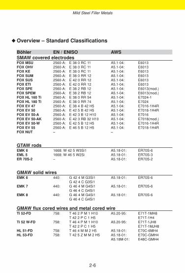
Overview – Standard Classifications
Böhler EN / ENISO AWSSMAW covered electrodesFOX MSU 2560-A: E 38 0 RC 11 A5.1-04: E6013FOX OHV 2560-A: E 38 0 RC 11 A5.1-04: E6013FOX KE 2560-A: E 38 0 RC 11 A5.1-04: E6013FOX SUM 2560-A: E 38 0 RR 12 A5.1-04: E6013FOX SUS 2560-A: E 42 0 RR 12 A5.1-04: E6013FOX ETI 2560-A: E 42 0 RR 12 A5.1-04: E6013FOX SPE 2560-A: E 38 2 RB 12 A5.1-04: E6013(mod.)FOX SPEM 2560-A: E 38 2 RB 12 A5.1-04: E6013(mod.)FOX HL 160 Ti 2560-A: E 38 0 RR 54 A5.1-04: E7024-1FOX HL 180 Ti 2560-A: E 38 0 RR 74 A5.1-04: E7024FOX EV 47 2560-A: E 38 4 B 42 H5 A5.1-04: E7016-1H4RFOX EV 50 2560-A: E 42 5 B 42 H5 A5.1-04: E7018-1H4RFOX EV 50-A 2560-A: E 42 3 B 12 H10 A5.1-04: E7016FOX EV 50-AK 2560-A: E 42 3 RB 32 H10 A5.1-04: E7018(mod.)FOX EV 50-W 2560-A: E 42 5 B 12 H5 A5.1-04: E7016-1H4RFOX EV 55 2560-A: E 46 5 B 12 H5 A5.1-04: E7018-1H4RFOX NUT – –
GTAW rodsEMK 6 1668: W 42 5 W3Si1 A5.18-01: ER70S-6 EML 5 1668: W 46 5 W2Si A5.18-01: ER70S-3ER 70S-2 – A5.18-01: ER70S-2
GMAW solid wiresEMK 6 440: G 42 4 M G3Si1 A5.18-01: ER70S-6
G 42 4 C G3Si1EMK 7 440: G 46 4 M G4Si1 A5.18-01: ER70S-6
G 46 4 C G4Si1EMK 8 440: G 46 4 M G4Si1 A5.18-01: ER70S-6
G 46 4 C G4Si1
GMAW flux cored wires and metal cored wireTi 52-FD 758: T 46 2 P M 1 H10 A5.20-95: E71T-1MH8
T 42 2 P C 1 H5 E71T-1H4Ti 52 W-FD 758: T 46 4 P M 1 H10 A5.20-95: E71T-1JH8
T 42 2 P C 1 H5 E71T-1MJH8HL 51-FD 758: T 46 4 M M 2 H5 A5.18-01: E70C-6MH4HL 53-FD 758: T 42 5 Z M M 2 H5 A5.18-01: E70C-GMH4
A5.18M-01: E48C-GMH4
◆
Mild Steel Filler Metals

2-7
Mild Steel Filler Metals
◆ Overview – Typical Chemical Composition
Böhler C Si Mn TiSMAW covered electrodesFOX MSU 0.06 0.4 0.5FOX OHV 0.06 0.4 0.45FOX KE 0.06 0.3 0.5FOX SUM 0.07 0.3 0.5FOX SUS 0.07 0.5 0.6FOX ETI 0.07 0.4 0.5FOX SPE 0.08 0.2 0.45FOX SPEM 0.08 0.3 0.6FOX HL 160 Ti 0.08 0.4 0.7FOX HL 180 Ti 0.07 0.5 0.8FOX EV 47 0.06 0.5 0.7FOX EV 50 0.07 0.5 1.1FOX EV 50-A 0.05 0.6 1.0FOX EV 50-AK 0.04 0.6 1.0FOX EV 50-W 0.07 0.5 1.1FOX EV 55 0.07 0.35 1.4FOX NUT – – –
GTAW rodsEMK 6 0.08 0.9 1.45EML 5 0.1 0.6 1.2ER 70S-2 0.05 0.5 1.2 + Al, Zr
GMAW solid wiresEMK 6 0.08 0.9 1.45
EMK 7 0.10 0.9 1.75
EMK 8 0.11 1.0 1.8
GMAW flux cored wires and metal cored wire
Ti 52-FD 0.06 0.5 1.2 +
Ti 52 W-FD 0.05 0.5 1.3 +
HL 51-FD 0.07 0.7 1.5
HL 53-FD 0.06 0.5 1.2 Ni 0.9

2-8
Overview – Standard Classifications (continued)
Böhler EN /ENISO AWSSAW wire/flux-combinationsEMS 2 756: S2 A5.17-97: EM12KEMS 2/BB 24 756: S 38 6 FB S2 A5.17-97: F7A8-EM12K
F48A6-EM12KEMS 2/BB 25 756: S 42 4 FB S2 A5.17-97: F7A4-EM12K
F48A4-EM12KEMS 2/BB 33 M 756: S 46 0 AR S2 A5.17-97: F7AZ-EM12K
F48A0-EM12KEMS 2/BF 16 756: S 38 0 MS S2 A5.17-97: F6A0-EM12K
F43A2-EM12KEMS 3 756: S3 A5.17-97: EH10K EMS 3/BB 24 756: S 42 4 FB S3 A5.17-97: F7A4-EH10K
F48A4-EH10KEMS 3/BB 25 756: S 42 3 FB S3 A5.17-97: F7A3-EH10K
F48A2-EH10KEMS 3/BB 33 M 756: S 50 0 AR S3 A5.17-97: F7AZ-EH10K
F48A0-EH10KEMS 3/BF 16 756: S 38 0 MS S3 A5.17-97: F6A0-EH10K
F43A 3-EH10K
Gas welding rodsBW VII 12536: O I A5.2-92: R45-G BW XII 12536: O III A5.2-92: R60-G
Mild Steel Filler Metals
◆

2-9
Overview – Standard Classifications (continued)
Böhler C Si Mn Ti NiSAW wire/flux-combinationsEMS 2 0.11 0.12 1.1EMS 2/BB 24 0.07 0.25 1.2
EMS 2/BB 25 0.07 0.4 1.45
EMS 2/BB 33 M 0.08 0.7 1.3
EMS 2/BF 16 0.04 0.5 1.3
EMS 3 0.12 0.1 1.5EMS 3/BB 24 0.08 0.25 1.5
EMS 3/BB 25 0.06 0.35 1.7
EMS 3/BB 33 M 0.08 0.75 1.7
EMS 3/BF 16 0.04 0.45 1.7
Gas welding rodsBW VII 0.08 0.1 0.6BW XII 0.10 0.15 1.1 0.45
Mild Steel Filler Metals
◆

Mechanical Properties of All-weld Metal(*) uYield strength Re N/mm2: 430 (≥ 380)Tensile strength Rm N/mm2: 490 (470 - 600)Elongation A (L0 = 5d0) %: 26 (≥ 320)Impact work ISO-V KV J + 20 °C: 75 (≥ 355)
± 0 °C: 60 (≥ 347)- 10 °C: 58
(*) u untreated, as-welded
Typical Composition of All-weld MetalC Si Mn
wt-% 0.06 0.4 0.5
DescriptionRutile-cellulosic electrode with good weldability in all positions including vertical-down. Viscous puddle, good gap bridging ability, easy handling.For industry and trade, assembly and shop welding.
BÖHLER FOX MSUSMAW rutile-cellulosic electrode,
mild steel
Base Materialssteels up to a yield strength of 380 N/mm2 (52 ksi)
S275JR, S235J0G3 - S355J0G3, P235GH, P265GH, P255NH, P235T1, P355T1, P235T2-P355T2, P235G1TH, P255G1TH, L210 - L360NB, L290MB, S235JRS1 - S235J0S1,S235JRS2 - S235J0S2ASTM A36 a. A53 Gr. all; A106 Gr. A, B, C A 135 Gr. A, B; A283 Gr. A, B, C, D; A366; A285Gr. A, B, C; A500 Gr. A, B, C; A570 Gr. 30, 33, 36, 40, 45; A607 Gr. 45; A668 Gr. A, B; A907Gr. 30, 33, 36, 40; A935 Gr.45; A936 Gr. 50; API 5 L Gr. B, X42 - X52
Operating Datare-drying: not necessary ø mm L mm amps A
2.5 250 70 - 100Electrode identification: 3.2 350 90 - 130FOX MSU 6013 E 38 0 RC 4.0 350 140 - 180
ENISO 2560-A:2005: E 38 0 RC 11ENISO 2560-B:2005: E 43 13 AAWS A5.1-04: E6013AWS A5.1M-04: E4313
2-10
Approvals and CertificatesTÜV-D (1104.), DB (10.014.01), ÖBB, ABS (2,2Y), BV (2Y), DNV (2), GL (2Y), LR (2m, 2Ym),RMR (2Y), SEPROZ, CE
Mild Steel Filler Metals – SMAW Covered Electrodes

DescriptionRutile-cellulosic electrode with good weldability in all positions including vertical-down. Mostpopular E6013 type.For small transformators, very good operating characteristics, flexible coating, good for tackwelding. Versatile applications in structural welding, vehicle construction, boiler and tankwelding, and in shipbuilding, also suitable for galvanised components.
Approvals and CertificatesTÜV-D (5687.), DB (10.014.12), ÖBB, TÜV-A (22), ABS (2), DNV (2), FI (E 38 0 RC 11), LR (2), LTSS, SEPROZ, CE
Base Materialssteels up to a yield strength of 380 N/mm2 (52 ksi)
S275JR, S235J0G3 - S355J0G3, P235GH, P265GH, P255NH, P235T1, P355T1, P235T2-P355T2, P235G1TH, P255G1TH, L210 - L360NB, L290MB, S235JRS1 - S235J0S1,S235JRS2 - S235J0S2ASTM A36 a. A53 Gr. all; A106 Gr. A, B, C A 135 Gr. A, B; A283 Gr. A, B, C, D; A366; A285Gr. A, B, C; A500 Gr. A, B, C; A570 Gr. 30, 33, 36, 40, 45; A607 Gr. 45; A668 Gr. A, B; A907Gr. 30, 33, 36, 40; A935 Gr.45; A936 Gr. 50; API 5 L Gr. B, X42 - X52
Operating Datare-drying: not necessary ø mm L mm amps A
2.0 250 45 - 180Electrode identification: 2.5 250/350 60 - 100FOX OHV 6013 E 38 0 RC 3.2 350 90 - 130
4.0 350/450 110 - 1705.0 450 170 - 240
Mechanical Properties of All-weld Metal(*) uYield strength Re N/mm2: 460 (≥ 380)Tensile strength Rm N/mm2: 520 (470 - 600)Elongation A (L0 = 5d0) %: 25 (≥ 320)Impact work ISO-V KV J + 20 °C: 75 (≥ 355)
± 0 °C: 60 (≥ 347)- 10 °C: 47
(*) u untreated, as-welded
Typical Composition of All-weld MetalC Si Mn
wt-% 0.06 0.4 0.45
ENISO 2560-A:2005: E 38 0 RC 11ENISO 2560-B:2005: E 43 13 AAWS A5.1-04: E6013AWS A5.1M-04: E4313
BÖHLER FOX OHVSMAW rutile-cellulosic electrode, mild steel
2-11
Mild Steel Filler Metals – SMAW Covered Electrodes

DescriptionRutile-cellulosic electrode engineered for easy operating in all positions including vertical-down. Excellent welding properties an A.C., good striking and restriking characteristics, sound penetration, flat beads; popular for general steel construction.
Approvals and CertificatesLR (2m), SEPROZ, ÖBB
Base Materialssteels up to a yield strength of 380 N/mm2 (52 ksi)
S275JR, S235J0G3 - S355J0G3, P235GH, P265GH, P255NH, P235T1, P355T1, P235T2-P355T2, P235G1TH, P255G1TH, L210 - L360NB, L290MB, S235JRS1 - S235J0S1,S235JRS2 - S235J0S2
ASTM A36 a. A53 Gr. all; A106 Gr. A, B, C A 135 Gr. A, B; A283 Gr. A, B, C, D; A366; A285Gr. A, B, C; A500 Gr. A, B, C; A570 Gr. 30, 33, 36, 40, 45; A607 Gr. 45; A668 Gr. A, B; A907Gr. 30, 33, 36, 40; A935 Gr.45; A936 Gr. 50; API 5 L Gr. B, X42 - X52
Operating Datare-drying: not necessary ø mm L mm amps A
2.0 250 45 - 380Electrode identification: 2.5 250/350 60 - 100FOX KE 6013 E 38 0 RC 3.2 350 90 - 130
4.0 350/450 110 - 170
Mechanical Properties of All-weld Metal(*) uYield strength Re N/mm2: 430 (≥ 380)Tensile strength Rm N/mm2: 490 (470 - 600)Elongation A (L0 = 5d0) %: 26 (≥ 320)Impact work ISO-V KV J + 20 °C: 75 (≥ 360)
± 0 °C: 65 (≥ 347)- 10 °C: 50
(*) u untreated, as-welded
Typical Composition of All-weld MetalC Si Mn
wt-% 0.06 0.3 0.5
ENISO 2560-A:2005:E 38 0 RC 11ENISO 2560-B:2005:E 43 13 AAWS A5.1-04: E6013AWS A5.1M-04: E4313
BÖHLER FOX KESMAW rutile-cellulosic electrode, mild steel
2-12
Mild Steel Filler Metals – SMAW Covered Electrodes

DescriptionRutile electrode with extraordinarily good weldability in all positions except vertical-down.Excellent welding properties on A.C., good striking and restriking characteristics.Soft arc, minimum spattering, very easy slag removal, famous for fine rippled and smooth weldsurfaces.
Approvals and Certificates–
Base Materialssteels up to a yield strength of 380 N/mm2 (52 ksi)
S275JR, S235J0G3 - S355J0G3, P235GH, P265GH, P255NH, P235T1, P355T1, P235T2-P355T2, P235G1TH, P255G1TH, L210 - L360NB, L290MB, S235JRS1 - S235J0S1,S235JRS2 - S235J0S2
ASTM A36 a. A53 Gr. all; A106 Gr. A, B, C A 135 Gr. A, B; A283 Gr. A, B, C, D; A366; A285Gr. A, B, C; A500 Gr. A, B, C; A570 Gr. 30, 33, 36, 40, 45; A607 Gr. 45; A668 Gr. A, B; A907Gr. 30, 33, 36, 40; A935 Gr.45; A936 Gr. 50; API 5 L Gr. B, X42 - X52
Operating Datare-drying: not necessary ø mm L mm amps A
2.5 350 60 - 100Electrode identification: 3.2 350 90 - 130 FOX SUM 6013 E 38 0 RR 4.0 350 110 - 170
Mechanical Properties of All-weld Metal(*) uYield strength Re N/mm2: 430 (≥ 380)Tensile strength Rm N/mm2: 500 (470 - 600)Elongation A (L0 = 5d0) %: 26 (≥ 320)Impact work ISO-V KV J + 20 °C: 75 (≥ 360)
± 0 °C: 60 (≥ 347)- 10 °C: (≥ 332)
(*) u untreated, as-welded
Typical Composition of All-weld MetalC Si Mn
wt-% 0.07 0.3 0.5
ENISO 2560-A:2005:E 38 0 RR 12ENISO 2560-B:2005:E 43 13 AAWS A5.1-04: E6013AWS A5.1M-04: E4313
BÖHLER FOX SUMSMAW rutile electrode, mild steel
2-13
Mild Steel Filler Metals – SMAW Covered Electrodes

DescriptionRutile electrode with excellent weldability in all positions except vertical-down, even under themost unfavourable conditions. Distinguished by excellent restriking characteristics, minimum spattering and excellent weldingproperties on A.C. The weld seam is characterised by fine rippled and smooth beads, the slagis self-detaching.
Approvals and CertificatesTÜV-D (1657.), DB (10.014.69), ÖBB, ABS (2), BV (2Y), DNV (2), GL (2), LR (X), SEPROZ,CE
Base Materialssteels up to a yield strength of 420 N/mm2 (60 ksi)
S275JR, S235J0G3 - S355J0G3, P235GH, P265GH, P255NH, P295GH, P235T1, P355T1,P235T2-P355T2, P235G1TH, P255G1TH, L210 - L360NB, L290MB, S235JRS1 - S235J0S1,S235JRS2 - S235J0S2
ASTM A36 a. A53 Gr. all; A106 Gr. A, B, C A 135 Gr. A, B; A283 Gr. A, B, C, D; A366; A285Gr. A, B, C; A500 Gr. A, B, C; A570 Gr. 30, 33, 36, 40, 45; A607 Gr. 45; A668 Gr. A, B; A907Gr. 30, 33, 36, 40; A935 Gr.45; A936 Gr. 50; API 5 L Gr. B, X42 - X56
Operating Datare-drying: not necessary ø mm L mm amps A
2.0 300 60 - 380Electrode identification: 2.5 350 80 - 100FOX SUS 6013 E 42 0 RR 3.2 350/450 120 - 150
4.0 450 160 - 2005.0 450 220 - 250
Mechanical Properties of All-weld Metal(*) uYield strength Re N/mm2: 430 (≥ 420)Tensile strength Rm N/mm2: 510 (500 - 640)Elongation A (L0 = 5d0) %: 27 (≥ 320)Impact work ISO-V KV J + 20 °C: 75 (≥ 360)
± 0 °C: 55 (≥ 347)- 10 °C: 45
(*) u untreated, as-welded
Typical Composition of All-weld MetalC Si Mn
wt-% 0.07 0.5 0.6
ENISO 2560-A:2005:E 42 0 RR 12ENISO 2560-B:2005:E 43 13 AAWS A5.1-04: E6013AWS A5.1M-04: E4313
BÖHLER FOX SUSSMAW rutile electrode, mild steel
2-14
Mild Steel Filler Metals – SMAW Covered Electrodes

DescriptionRutile electrode offering top weldability in all positions except vertical-down. Extremely smoothbeads, self-detaching slag, minimum spattering and excellent welding properties on A.C.Excellent restriking characteristics and easy handling. Good deposition lengths attainable.Versatile applications in trade and industry.
Approvals and CertificatesTÜV-D (1097.), TÜV-A (450), ABS (2), BV (2), DNV (2), FI (E 42 0 RR 12), GL (2), LR (2m),LTSS, SEPROZ, CE
Base Materialssteels up to a yield strength of 420 N/mm2 (60 ksi)
S275JR, S235J0G3 - S355J0G3, P235GH, P265GH, P255NH, P295GH, P235T1, P355T1,P235T2-P355T2, P235G1TH, P255G1TH, L210 - L360NB, L290MB, S235JRS1 - S235J0S1,S235JRS2 - S235J0S2
ASTM A36 a. A53 Gr. all; A106 Gr. A, B, C; A 135 Gr. A, B; A283 Gr. A, B, C, D; A366; A285Gr. A, B, C; A500 Gr. A, B, C; A570 Gr. 30, 33, 36, 40, 45; A607 Gr. 45; A668 Gr. A, B; A907Gr. 30, 33, 36, 40; A935 Gr. 45; A936 Gr. 50; API 5 L Gr. B, X42 - X56
Operating Datare-drying: not necessary ø mm L mm amps A
1.5 250 40 - 360Electrode identification: 2.0 250 45 - 380FOX ETI 6013 E 42 0 RR 2.5 250/350 60 - 110
3.2 350/450 90 - 1404.0 450 110 - 1905.0 450 170 - 240
Mechanical Properties of All-weld Metal(*) uYield strength Re N/mm2: 460 (≥ 420)Tensile strength Rm N/mm2: 520 (500 - 640)Elongation A (L0 = 5d0) %: 26 (≥ 320)Impact work ISO-V KV J + 20 °C: 65 (≥ 350)
± 0 °C: 50 (≥ 347)(*) u untreated, as-welded
Typical Composition of All-weld MetalsC Si Mn
wt-% 0.07 0.4 0.5
ENISO 2560-A:2005:E 42 0 RR 12ENISO 2560-B:2005:E 43 13 AAWS A5.1-04: E6013AWS A5.1M-04: E4313
BÖHLER FOX ETISMAW rutile electrode, mild steel
2-15
Mild Steel Filler Metals – SMAW Covered Electrodes

DescriptionRutile-basic coated electrode especially recommended for out-of-position work except vertical-down. Excellently suited for welding root passes. Produces first class X-ray quality welds.Excellent welding properties on A.C.
Preferably used in structural and tank welding as well as in tube&pipe construction. Highmechanical properties, thus suitable for many different base metals.
Approvals and CertificatesTÜV-D (0731.), DB (10.014.03), ÖBB, TÜV-A (74), LTSS, SEPROZ, CE
Base Materialssteels up to a yield strength of 380 N/mm2 (52 ksi)
S275JR, S235J2G3 - S355J2G3, P235GH, P265GH, P255NH, P235T1-P355T1, P235T2-P355T2, P235G1TH, P255G1TH, L210 - L360NB, L290MB - L360MB, S235JRS1 - S235J2S1,S235JRS2 - S235J2S2
ASTM A36 a. A53 Gr. all; A106 Gr. A, B, C; A135 Gr. A, B; A283 Gr. A, B, C, D; A366; A285Gr. A, B, C; A500 Gr. A, B, C; A570 Gr. 30, 33, 36, 40, 45; A607 Gr. 45; A668 Gr. A, B; A907Gr. 30, 33, 36, 40; A935 Gr. 45; A936 Gr. 50; API 5 L Gr. B, X42 - X52
Operating Datare-drying: not necessary ø mm L mm amps A
2.0 250 45 - 375Electrode identification: 2.5 250/350 60 - 100FOX SPE E 38 2 RB 3.2 350 90 - 140
4.0 450 110 - 1905.0 450 170 - 250
Mechanical Properties of All-weld Metal(*) uYield strength Re N/mm2: 420 (≥ 380)Tensile strength Rm N/mm2: 500 (470 - 600)Elongation A (L0 = 5d0) %: 28 (≥ 320)Impact work ISO-V KV J + 20 °C: 90 (≥ 370)
± 0 °C: 75 (≥ 360)- 10 °C: 70 (≥ 350)- 20 °C: 60 (≥ 347)
(*) u untreated, as-welded
Typical Composition of All-weld MetalC Si Mn
wt-% 0.08 0.2 0.45
ENISO 2560-A:2005:E 38 2 RB 12ENISO 2560-B:2005:E 43 03 A UAWS A5.1-04: E6013(mod.)AWS A5.1M-04: E4313(mod.)
BÖHLER FOX SPESMAW electrode, mild steel,
rutile-basic-coated
2-16
Mild Steel Filler Metals – SMAW Covered Electrodes
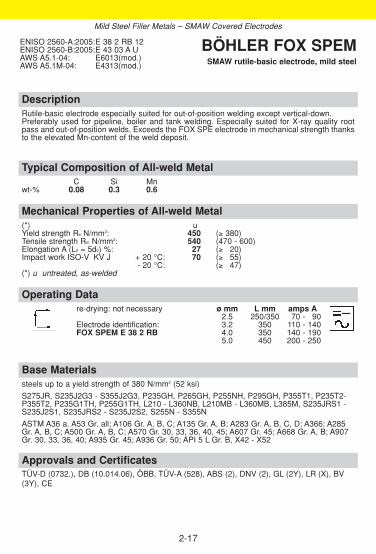
DescriptionRutile-basic electrode especially suited for out-of-position welding except vertical-down. Preferably used for pipeline, boiler and tank welding. Especially suited for X-ray quality rootpass and out-of-position welds. Exceeds the FOX SPE electrode in mechanical strength thanksto the elevated Mn-content of the weld deposit.
Approvals and CertificatesTÜV-D (0732.), DB (10.014.06), ÖBB, TÜV-A (528), ABS (2), DNV (2), GL (2Y), LR (X), BV(3Y), CE
Base Materialssteels up to a yield strength of 380 N/mm2 (52 ksi)
S275JR, S235J2G3 - S355J2G3, P235GH, P265GH, P255NH, P295GH, P355T1, P235T2-P355T2, P235G1TH, P255G1TH, L210 - L360NB, L210MB - L360MB, L385M, S235JRS1 -S235J2S1, S235JRS2 - S235J2S2, S255N - S355N
ASTM A36 a. A53 Gr. all; A106 Gr. A, B, C; A135 Gr. A, B; A283 Gr. A, B, C, D; A366; A285Gr. A, B, C; A500 Gr. A, B, C; A570 Gr. 30, 33, 36, 40, 45; A607 Gr. 45; A668 Gr. A, B; A907Gr. 30, 33, 36, 40; A935 Gr. 45; A936 Gr. 50; API 5 L Gr. B, X42 - X52
Operating Datare-drying: not necessary ø mm L mm amps A
2.5 250/350 70 - 390Electrode identification: 3.2 350 110 - 140FOX SPEM E 38 2 RB 4.0 350 140 - 190
5.0 450 200 - 250
Mechanical Properties of All-weld Metal(*) uYield strength Re N/mm2: 450 (≥ 380)Tensile strength Rm N/mm2: 540 (470 - 600)Elongation A (L0 = 5d0) %: 27 (≥ 320)Impact work ISO-V KV J + 20 °C: 70 (≥ 355)
- 20 °C: (≥ 347)(*) u untreated, as-welded
Typical Composition of All-weld MetalC Si Mn
wt-% 0.08 0.3 0.6
ENISO 2560-A:2005:E 38 2 RB 12ENISO 2560-B:2005:E 43 03 A UAWS A5.1-04: E6013(mod.)AWS A5.1M-04: E4313(mod.)
BÖHLER FOX SPEMSMAW rutile-basic electrode, mild steel
2-17
Mild Steel Filler Metals – SMAW Covered Electrodes

DescriptionRutile electrode, high efficiency with 160 % metal recovery. Fast flowing puddle. Easy slagremoval in fillet welds in acute angles. Useable for rusty and coated steels and plates.Preferred for fillet and butt welds in horizontal position.
Approvals and CertificatesABS (2,2Y*), GL (2Y), LR (X), SEPROZ
Base Materialssteels up to a yield strength of 380 N/mm2 (52 ksi)
S235JR, S275JR, S235J0G3, S275J0G3, S355J0G3, P235GH, P265GH, S255N, P295GH,S235JRS1 - S235J0S1, S235JRS2 - S235J0S2
ASTM A36 Gr. all; A283 Gr. A, B, C, D; A285 Gr. A, B, C; A366; A570 Gr. 30, 33, 36, 40, 45;A607 Gr. 45; A668 Gr. A, B; A907 Gr. 30, 33, 36, 40; A935 Gr. 45; A936 Gr. 50
Operating Datare-drying: not necessary ø mm L mm amps A
3.2 450 140 - 180Electrode identification: 4.0 450 190 - 230FOX HL 160 Ti 7024-1 E 38 0 RR 5.0 450 240 - 280
Mechanical Properties of All-weld Metal(*) uYield strength Re N/mm2: 420 (≥ 400)Tensile strength Rm N/mm2: 520 (490 - 600)Elongation A (L0 = 5d0) %: 26 (≥ 322)Impact work ISO-V KV J + 20 °C: 100 (≥ 370)
± 0 °C: (≥ 347)- 20 °C: 30 (≥ 327)
(*) u untreated, as-welded
Typical Composition of All-weld MetalC Si Mn
wt-% 0.08 0.4 0.7
ENISO 2560-A:2005:E 38 0 RR 54ENISO 2560-B:2005:E 49 24-1 AAWS A5.1-04: E7024-1AWS A5.1M-04: E4924-1
BÖHLER FOX HL 160 TiSMAW rutile electrode, mild steel,
high efficiency
2-18
Mild Steel Filler Metals – SMAW Covered Electrodes

DescriptionRutile iron powder electrode yielding approx. 180 % metal recovery. Self-detaching slag,smooth welds free of undercuts. Excellent striking characteristics. Highly economical for multi-layer welding of heavy crosssections.
Approvals and CertificatesTÜV-A (17), ABS (2), DNV (2), FI (E 38 0 RR 74), GL (2Y), LR (2m), RINA (2), SEPROZ,ÖBB, RMR (2)
Base Materialssteels up to a yield strength of 380 N/mm2 (52 ksi)
S235JR, S275JR, S235J0G3, S275J0G3, S355J0G3, P235GH, P265GH, S255N, P295GH,S235JRS1 - S235J0S1, S235JRS2 - S235J0S2
ASTM A36 Gr. all; A283 Gr. A, B, C, D; A285 Gr. A, B, C; A366; A570 Gr. 30, 33, 36, 40, 45;A607 Gr. 45; A668 Gr. A, B; A907 Gr. 30, 33, 36, 40; A935 Gr. 45; A936 Gr. 50
Operating Datare-drying: not necessary ø mm L mm amps A
3.2 450 120 - 180Electrode identification: 4.0 450 160 - 230FOX HL 180 Ti 7024 E 38 0 RR 5.0 450 200 - 330
Mechanical Properties of All-weld Metal(*) uYield strength Re N/mm2: 440 (≥ 400)Tensile strength Rm N/mm2: 510 (490 - 600)Elongation A (L0 = 5d0) %: 27 (≥ 322)Impact work ISO-V KV J + 20 °C: 85 (≥ 360)
± 0 °C: 65 (≥ 347)- 10 °C: 50
(*) u untreated, as-welded
Typical Composition of All-weld MetalC Si Mn
wt-% 0.07 0.5 0.8
ENISO 2560-A:2005:E 38 0 RR 74ENISO 2560-B:2005:E 49 24 AAWS A5.1-04: E7024AWS A5.1M-04: E4924
BÖHLER FOX HL 180 TiSMAW rutile electrode, mild steel,
high efficiency
2-19
Mild Steel Filler Metals – SMAW Covered Electrodes

DescriptionBasic electrode for high-quality welds. Good weldability in all positions except vertical-down.Metal recovery about 110 %. Very low hydrogen content (according AWS condition HD < 4 ml/100 g weld metal). Weld metal extremely ductile, crack resistant and ageing resistant thus especially suited forrigid weldments with heavy seam cross sections.
Approvals and CertificatesTÜV-D (1098.), DB (10.014.09), ÖBB, TÜV-A (72), ABS (3H5), BV (3HHH), DNV (3H10), GL (3H5), LR (3m H5), RMR (2), RINA (3YH5, 3H5), LTSS, VUZ, SEPROZ, CE
Base Materialssteels up to a yield strength of 380 N/mm2 (52 ksi)
S235JR-E295, S235J2G3 - S355J2G3, C22, P235T1-P275T1, P235T2, P275T2, L210 -L320, L290MB - L320MB, P235G1TH, P255G1TH, P235GH, P265GH, P295GH, S235JRS1 -S235J4S, S355G1S - S355G3S, S255N - S355N, P255NH-P355NH, S255NL - S355NL,GE200-GE240
ASTM A 27 a. A36 Gr. all; A214; A 242 Gr. 1-5; A266 Gr. 1, 2, 4; A283 Gr. A, B, C, D; A285 Gr. A, B, C; A299 Gr. A, B; A328; A366; A515 Gr. 60, 65, 70; A516 Gr. 55; A570 Gr. 30, 33,36, 40, 45; A 572 Gr. 42, 50; A606 Gr. all; A607 Gr. 45; A656 Gr. 50, 60; A668 Gr. A, B; A907Gr. 30, 33, 36, 40; A841; A851 Gr. 1, 2; A935 Gr. 45; A936 Gr. 50; API 5 L Gr. B, X42 - X52
Operating Datare-drying if necessary: ø mm L mm amps A300 - 350 °C, min. 2 h 2.5 250/350 80 - 110Electrode identification: 3.2 350/450 100 - 140FOX EV 47 7016-1 E 38 4 B 4.0 450 130 - 180
5.0 450 180 - 230
Mechanical Properties of All-weld Metal(*) u sYield strength Re N/mm2: 460 (≥ 400) 400 (≥ 360)Tensile strength Rm N/mm2: 530 (490 - 600) 500 (450 - 580) Elongation A (L0 = 5d0) %: 27 (≥ 322) 29 (≥ 22) Impact work ISO-V KV J + 20 °C: 190 (≥ 110) 200 (≥ 110)
- 20 °C: 110 150- 40 °C: 90 (≥ 347) 100
(*) u untreated, as-weldeds stress relieved 600 °C/2 h/furnace down to 300 °C/air
Typical Composition of All-weld MetalC Si Mn
wt-% 0.06 0.5 0.7
ENISO 2560-A:2005:E 38 4 B 42 H5ENISO 2560-B:2005:E 49 16-1 A U H5AWS A5.1-04: E7016-1H4RAWS A5.1M-04: E4916-1H4R
BÖHLER FOX EV 47SMAW basic electrode, mild steel
2-20
Mild Steel Filler Metals – SMAW Covered Electrodes
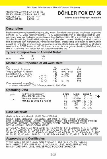
DescriptionBasic electrode engineered for high-quality welds. Excellent strength and toughness propertiesdown to -50 °C. Metal recovery approx. 110 %. Good weldability in all position except for verti-cal-down. Very low hydrogen content (according AWS condition HD < 4 ml/100 g weld metal).Suitable for welding steels with low purity and high carbon content. Welding in steel construc-tion, boiler and tank manufacture, vehicle construction, shipbuilding, and machine constructionas well as for buffer layers on build ups on high carbon steels. Especially suitable for off-shoreconstruction, CODT tested at -10 °C. It can be used in sour gas applications (HIC-Test acc.NACE TM-02-84). Test values for SSC-test are available too.
Approvals and CertificatesTÜV-D (0426.), DB (10.014.02), ÖBB, TÜV-A (32), ABS (3H5, 4Y), BV (3YHHH), DNV (3YH10), FI (E 42 5 B 42 H5), GL (4Y40H15), LR (3, 3YH5), RMR (3YHH), RINA (4YDH5/4DH5), LTSS, VUZ, SEPROZ, PDO, CRS (3YH5), CE
Base Materialssteels up to a yield strength of 420 N/mm2 (60 ksi)S235JR-E335, S235J2G3 - S355J2G3, C22, P235T1-P355T1, P235T2, P355T2, L210 - L360NB L290MB - L320MB, P235G1TH, P255G1TH, P235GH, P265GH, P295GH,S235JRS1 - S235J4S, S355G1S - S355G3S, S255N - S355N, P255NH-P355NH, S255NL - S355NL, GE200-GE260, GE300ASTM A 27 a. A36 Gr. all; A214; A 242 Gr. 1-5; A266 Gr. 1, 2, 4; A283 Gr. A, B, C, D; A285 Gr. A, B, C; A299 Gr. A, B; A328; A366; A515 Gr. 60, 65, 70; A516 Gr. 55; A570 Gr. 30, 33,36, 40, 45; A 572 Gr. 42, 50; A606 Gr. all; A607 Gr. 45; A656 Gr. 50, 60; A668 Gr. A, B; A907Gr. 30, 33, 36, 40; A841; A851 Gr. 1, 2; A935 Gr. 45; A936 Gr. 50; API 5 L Gr. B, X42 - X56
Operating Datare-drying if necessary: ø mm L mm amps A300 - 350 °C, min. 2 h 2.0 250 50 - 370Electrode identification: 2.5 250/350 80 - 110FOX EV 50 7018-1 E 42 5 B 3.2 350/450 100 - 140
4.0 450 130 - 1805.0 450 180 - 2306.0 450 240 - 290
Mechanical Properties of All-weld Metal(*) u sYield strength Re N/mm2: 490 (≥ 420) 430Tensile strength Rm N/mm2: 560 (500 - 640) 520Elongation A (L0 = 5d0) %: 27 (≥ 322) 29Impact work ISO-V KV J + 20 °C: 190 (≥ 120) 220
- 20 °C: 160 190- 50 °C: 100 (≥ 347) 140
(*) u untreated, as-weldeds stress relieved 600 °C/2 h/furnace down to 300 °C/air
Typical Composition of All-weld MetalC Si Mn
wt-% 0.07 0.5 1.1
ENISO 2560-A:2005:E 42 5 B 42 H5ENISO 2560-B:2005:E 49 18-1 A U H5AWS A5.1-04: E7018-1H4RAWS A5.1M-04: E4918-1H4R
BÖHLER FOX EV 50SMAW basic electrode, mild steel
2-21
Mild Steel Filler Metals – SMAW Covered Electrodes

DescriptionBasic double electrode with excellent weldability in all positions except vertical-down.Especially suited for out-of-position welding thanks to the well controlled arc. Excellent root penetration. Good suitability for welding on AC Minimum spatter loss. Very easyslag removal with uniform beads. Well suited for small transformers. Low hydrogen content inthe weld deposit (HD < 10 ml/100 g deposit).
Approvals and CertificatesTÜV-D (7105.), DB (10.014.17), ÖBB, CE
Base Materialssteels up to a yield strength of 420 N/mm2 (60 ksi)
S235J2G3 - S355J2G3, S235JR-E295, C22, P235T1-P355T1, P235T2-P355T2, L210 - L360NB, L290MB - L360MB, P235G1TH, P255G1TH, P235GH, P265GH, S255N,P295GH, S235JRS1 - S235J3S, S355G1S - S355G3S, S255N - S355N, P255NH-P355NH,GE200-GE260
ASTM A27 a. A36 Gr. all; A214; A242 Gr. 1-5; A266 Gr. 1, 2, 4; A283 Gr. A, B, C, D; A285 Gr. A, B, C; A299 Gr. A, B; A328; A366; A515 Gr. 60, 65, 70; A516 Gr. 55; A570 Gr. 30, 33,36, 40, 45; A 572 Gr. 42, 50; A606 Gr. all; A607 Gr. 45; A656 Gr. 50, 60; A668 Gr. A, B; A907Gr. 30, 33, 36, 40; A841; A851 Gr. 1, 2; A935 Gr. 45; A936 Gr. 50; API 5 L Gr. B, X42 - X56
Operating Datare-drying if necessary: ø mm L mm amps A300 - 350 °C, min. 2 h 2.5 350 60 - 390Electrode identification: 3.2 350/450 100 - 150FOX EV 50-A 7016 E 42 3 B 4.0 450 140 - 190
5.0 450 190 - 250
Mechanical Properties of All-weld Metal(*) u sYield strength Re N/mm2: 440 (≥ 420) 400Tensile strength Rm N/mm2: 550 (500 - 640) 520Elongation A (L0 = 5d0) %: 28 (≥ 320) 28Impact work ISO-V KV J + 20 °C: 180 (≥ 100) 180
- 30 °C: (≥ 347)(*) u untreated, as-welded
s stress relieved 580 °C/2 h/furnace down to 300 °C/air
Typical Composition of All-weld MetalC Si Mn
wt-% 0.05 0.6 1.0
ENISO 2560-A:2005:E 42 3 B 12 H10ENISO 2560-B:2005:E 49 16 A U H10AWS A5.1-04: E7016AWS A5.1M-04: E4916
BÖHLER FOX EV 50-ASMAW basic electrode, mild steel
2-22
Mild Steel Filler Metals – SMAW Covered Electrodes

DescriptionRutile basic electrode for high quality weld joints. Specially suited for welding on A.C. Goodweldability in all position except vertical down. Increased weld metal recovery of app. 125 %.
Approvals and CertificatesLTSS
Base Materialssteels up to a yield strength of 420 N/mm2 (60 ksi)
S235JR-E335, S235J2G3 - S355J2G3, C22, P235T1-P355T1, P235T2, P355T2, L210 -L360NB, L290MB, P235G1TH, P255G1TH, P235GH, P265GH, P295GH, S235JRS1 -S235J3S, S355G1S - S355G3S, S255N - S355N, P255NH-P355NH, S255NL - S355NL,GE200-GE260, GE300
ASTM A27 a. A36 Gr. all; A214; A 242 Gr. 1-5; A266 Gr. 1, 2, 4; A283 Gr. A, B, C, D; A285 Gr. A, B, C; A299 Gr. A, B; A328; A366; A515 Gr. 60, 65, 70; A516 Gr. 55; A570 Gr. 30, 33,36, 40, 45; A 572 Gr. 42, 50; A606 Gr. all; A607 Gr. 45; A656 Gr. 50, 60; A668 Gr. A, B; A907Gr. 30, 33, 36, 40; A841; A851 Gr. 1, 2; A935 Gr. 45; A936 Gr. 50; API 5 L Gr. B, X42 - X56
Operating Datare-drying if necessary: ø mm L mm amps A300 - 350 °C, min. 2 h 2.5 250 70 - 390Electrode identification: 3.2 350 100 - 140FOX EV 50-AK E 42 3 RB 4.0 450 150 - 210
Mechanical Properties of All-weld Metal(*) uYield strength Re N/mm2: 480 (≥ 420)Tensile strength Rm N/mm2: 560 (500 - 640)Elongation A (L0 = 5d0) %: 30 (≥ 322)Impact work ISO-V KV J + 20 °C: 200 (≥ 120)
- 20 °C: 140- 30 °C: (≥ 347)
(*) u untreated, as-welded
Typical Composition of All-weld MetalC Si Mn
wt-% 0.04 0.6 1.0
ENISO 2560-A:2005:E 42 3 RB 32 H10ENISO 2560-B:2005:E 49 03 A U H10AWS A5.1-04: E7018(mod.)AWS A5.1M-04: E4918(mod.)
BÖHLER FOX EV 50-AKSMAW rutile basic electrode, mild steel
2-23
Mild Steel Filler Metals – SMAW Covered Electrodes

DescriptionBasic electrode for high-quality joint welds. Especially suited for root pass welding. Excellentweldability in all positions except vertical-down. Smooth and slag-free welds. Crack resistantdeposits of high toughness at ambient and subzero temperatures. Very low hydrogen contentsin the weld deposit (according AWS condition HD < 4 ml/100 g weld metal). Especially suited for welding on AC. For root pass welding, DC negative polarity is recommended.
Approvals and CertificatesTÜV-D (4180.), FI (E 42 2 B 12 H5), GL (3YH5), LTSS, PDO, SEPROZ
Base Materialssteels up to a yield strength of 420 N/mm2 (60 ksi)
S235JR-E335, S235J2G3 - S355J2G3, C22, P235T1-P355T1, P235T2, P355T2, L210 - L360NB, L290MB, P235G1TH, P255G1TH, P235GH, P265GH, P295GH, S235JRS1 - S235J4S, S355G1S - S355G3S, S255N - S355N, P255NH-P355NH, S255NL - S355NL, GE200-GE260, GE300
ASTM A27 a. A36 Gr. all; A214; A 242 Gr. 1-5; A266 Gr. 1, 2, 4; A283 Gr. A, B, C, D; A285 Gr. A, B, C; A299 Gr. A, B; A328; A366; A515 Gr. 60, 65, 70; A516 Gr. 55; A570 Gr. 30, 33,36, 40, 45; A 572 Gr. 42, 50; A606 Gr. all; A607 Gr. 45; A656 Gr. 50, 60; A668 Gr. A, B; A907Gr. 30, 33, 36, 40; A841; A851 Gr. 1, 2; A935 Gr. 45; A936 Gr. 50; API 5 L Gr. B, X42 - X56
Operating Datare-drying if necessary: ø mm L mm amps A300 - 350 °C, min. 2 h 2.0 300 40 - 160Electrode identification: 2.5 350 55 - 185FOX EV 50-W 7016-1 E 42 5 B 3.2 350 80 - 140
4.0 350 110 - 1805.0 450 180 - 230
Mechanical Properties of All-weld Metal(*) u sYield strength Re N/mm2: 460 (≥ 420) 400Tensile strength Rm N/mm2: 560 (510 - 640) 520Elongation A (L0 = 5d0) %: 28 (≥ 325) 28Impact work ISO-V KV J + 20 °C: 200 (≥ 110) 200
- 20 °C: 150 160- 40 °C: 120 130- 50 °C: (≥ 347)
(*) u untreated, as-weldeds stress relieved 580 °C/2 h/furnace down to 300 °C/air
Typical Composition of All-weld MetalC Si Mn
wt-% 0.07 0.5 1.1
ENISO 2560-A:2005:E 42 5 B 12 H5ENISO 2560-B:2005:E 49 16-1 A U H5AWS A5.1-04: E7016-1H4RAWS A5.1M-04: E4916-1H4R
BÖHLER FOX EV 50-WSMAW basic electrode, mild steel
2-24
Mild Steel Filler Metals – SMAW Covered Electrodes
Polarity negative for root pass
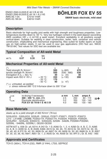
DescriptionBasic electrode for high-quality joint welds with high strength and toughness properties. Low-temperature ductility down to -50 °C. Very low hydrogen content in the weld deposit (accordingAWS condition HD < 4 ml/100 g weld metal). Excellent weldability in all positions except vertical-down. Suitable for welding in steel construction, boiler, tank, container and vehicle construction, shipbuilding and mechanical engineering. Also suited for buffer layers on buildups on high-carbon steels. It can be used in sour gas applications (HIC-Test acc. NACE TM-02-84). Test values for SSC-test are available too.
Approvals and CertificatesTÜV-D (3654.), TÜV-A (232), RMR (3 YHH), LTSS, SEPROZ
Base Materialssteels up to a yield strength of 460 N/mm2 (78 ksi)
S235J2G3 - S355J2G3, S235JR - S355J0, P235T1-P355T1, P235T2 -P355T2, L210 - L415NB, L290MB, P235G1TH, P255G1TH, P235GH, P265GH, P295GH, S235JRS1 - S235J4S, S355G1S - S355G3S, S255N - S460N, P255NH-P355NH, S255NL - S460NL, S255NL1, GE200-GE300
ASTM A27 a. A36 Gr. all; A214; A 242 Gr. 1-5; A266 Gr. 1, 2, 4; A283 Gr. A, B, C, D; A285 Gr. A, B, C; A299 Gr. A, B; A328; A366; A515 Gr. 60, 65, 70; A516 Gr. 55; A570 Gr. 30, 33,36, 40, 45; A 572 Gr. 42, 50; A606 Gr. all; A607 Gr. 45; A656 Gr. 50, 60; A668 Gr. A, B; A907Gr. 30, 33, 36, 40; A841; A851 Gr. 1, 2; A935 Gr. 45; A936 Gr. 50; API 5 L Gr. B, X42 - X60
Operating Datare-drying if necessary: ø mm L mm amps A300 - 350 °C, min. 2 h 2.5 250 80 - 110Electrode identification: 3.2 350 100 - 140FOX EV 55 7018-1 E 46 5 B 4.0 450 130 - 180
Mechanical Properties of All-weld Metal(*) u sYield strength Re N/mm2: 500 (≥ 460) 470tensile strength Rm N/mm2: 550 (530 - 680) 530Elongation A (L0 = 5d0) %: 30 (≥ 322) 30Impact work ISO-V KV J + 20 °C: 220 (≥ 130) 200
- 20 °C: 170- 50 °C: 90 (≥ 347)
(*) u untreated, as-weldeds stress relieved 580 °C/2 h/furnace down to 300 °C/air
Typical Composition of All-weld MetalC Si Mn
wt-% 0.07 0.35 1.4
ENISO 2560-A:2005:E 46 5 B 42 H5ENISO 2560-B:2005:E 49 18-1 A U H5AWS A5.1-04: E7018-1H4RAWS A5.1M-04: E4918-1H4R
BÖHLER FOX EV 55SMAW basic electrode, mild steel
2-25
Mild Steel Filler Metals – SMAW Covered Electrodes

DescriptionSpecial electrode for gouging of various base Materials without oxygen. High gouging speed inall positions useable. Suitable for edge bevelling, cutting grooves, removal of unsound material and cracks prior torepair welding.
Operating Datare-drying: not necessary ø mm L mm amps AElectrode identification: 3.2 350 180 - 240FOX NUT 4.0 350 250 - 320
BÖHLER FOX NUTSMAW covered electrode, mild steel,
gouging electrode
2-26
Mild Steel Filler Metals – SMAW Covered Electrodes
Approvals and Certificates–

DescriptionGTAW rod with high silicon content. The welding rod is suited for joints in boiler and vesselfabrication as well as in structural steel engineering.It can be used in sour gas applications (HIC-Test acc. NACE TM-02-84). Test values for SSC-test are available too.
Approvals and CertificatesTÜV-D (09717.), TÜV-A (521), LTSS, SEPROZ, CE
Base Materialssteels up to a yield strength of 420 N/mm2 (60 ksi)
S235J2G3-S355J2G3, E360, P235T1-P355T1, P235G1TH, L210, L290MB, P255G1TH,P235GH, P265GH, P295GH, P310GH, P255NH, S235JRS1-S235J4S, S355G1S-S355G3S,S255N-S385N, P255NH-P385NH, GE200-GE260
ASTM A27 a. A36 Gr. all; A214; A 242 Gr. 1-5; A266 Gr. 1, 2, 4; A283 Gr. A, B, C, D; A285 Gr. A, B, C; A299 Gr. A, B; A328; A366; A515 Gr. 60, 65, 70; A516 Gr. 55; A570 Gr. 30, 33,36, 40, 45; A 572 Gr. 42, 50; A606 Gr. all; A607 Gr. 45; A656 Gr. 50, 60; A668 Gr. A, B; A907Gr. 30, 33, 36, 40; A841; A851 Gr. 1, 2; A935 Gr. 45; A936 Gr. 50; API 5 L Gr. B, X42 - X56
Operating Datashielding gases: Argon ø mmrod marking: 1.6
front: W3Si1 2.0back: ER70S-6 2.4
Mechanical Properties of All-weld Metal(*) u sYield strength Re N/mm2: 430 (≥ 420) 400Tensile strength Rm N/mm2: 540 (500 - 640) 510Elongation A (L0 = 5d0) %: 27 (≥ 320) 28Impact work ISO-V KV J + 20 °C: 160 (≥ 100) 180
- 40 °C: 70 110- 50 °C: (≥ 347)
(*) u untreated, as-welded – shielding gas Argons stress relieved, 620 °C/2 h – shielding gas 100 % Argon
Typical Composition of Welding RodC Si Mn
wt-% 0.08 0.9 1.45
EN 1668:1997: W 42 5 W3Si1AWS A5.18-01: ER70S-6 AWS A5.18M-01: ER48S-6W.Nr: 1.5125
BÖHLER EMK 6GTAW rod, mild steel
2-27
Mild Steel Filler Metals – GTAW Rods

DescriptionGTAW rod for high integrity welds. The low Si-content renders this filler metal particularly alsofor joint welds that are subjected to enamelling or galvanising. Especially suited for root pass welding (approved at -50 °C)
BÖHLER EML 5 can be used in sour gas applications (HIC-Test acc. NACE TM-02-84) as well.
Approvals and CertificatesTÜV-D (1096.), DB (42.014.02), ÖBB, TÜV-A (373), Statoil, CE
Base Materialssteels up to a yield strength of 460 N/mm2 (67 ksi)
S235J2G3 - S355J2G3, E360, P235T1-P355T1, P235G1TH, L210, L290MB, P255G1TH,P235GH, P265GH, P295GH, P310GH, P255NH, S235JRS1 - S235J4S, S355G1S - S355G3S, S255N - S385N, P255NH-P385NH, GE200-GE260
ASTM A27 a. A36 Gr. all; A214; A242 Gr. 1-5; A266 Gr. 1, 2, 4; A283 Gr. A, B, C, D; A285 Gr. A, B, C; A299 Gr. A, B; A328; A366; A515 Gr. 60, 65, 70; A516 Gr. 55; A570 Gr. 30, 33,36, 40, 45; A 572 Gr. 42, 50; A606 Gr. all; A607 Gr. 45; A656 Gr. 50, 60; A668 Gr. A, B; A907Gr. 30, 33, 36, 40; A841; A851 Gr. 1, 2; A935 Gr. 45; A936 Gr. 50; API 5 L Gr. B, X42 - X60
Operating Datashielding gases: 100 % Argon ø mmrod marking: 1.6
front: W2Si 2.0back: ER70S-3 2.4
3.0
Mechanical Properties of All-weld Metal(*) u sYield strength Re N/mm2: 500 (≥ 460) 490Tensile strength Rm N/mm2: 600 (530 - 680) 570Elongation A (L0 = 5d0) %: 26 (≥ 323) 30Impact work ISO-V KV J + 20 °C: 220 (≥ 130) 200
- 20 °C: 200 210- 50 °C: (≥ 347)
(*) u untreated, as-welded – shielding gas 100 % Argons stress relieved, 620 °C/5 h – shielding gas 100 % Argon
Typical Composition of Welding RodC Si Mn
wt-% 0.1 0.6 1.2
EN 1668:1997: W 46 5 W2SiAWS A5.18-01: ER70S-3AWS A5.18M-01: ER48S-3
BÖHLER EML 5GTAW rod, mild steel
2-28
Mild Steel Filler Metals – GTAW Rods

2-29
DescriptionBöhler ER 70S-2 is a copper GTAW rod containing Al, Ti and Zr as strong deoxidents in addi-tion to Mn and Si and is often referred to as triple deoxidised.This has advantages when rimming or semi-killed mild steels are welded or where jointpreparations are rusty or contaminated.Böhler ER 70S-2 is primarily used for single pass welding. For applications involving single andmultipass GTAW and/or low temperature toughness requirements down to -50 °C we recom-mend our GTAW rod Böhler EML 5 (AWS ER 70S-3).
Approvals and Certificates–
Base Materialsespecially for rod pass welding of steels up to a yield strength of 420 N/mm2 (60 ksi)
S235J2G3, E360, P235T1, P235G1TH, L210, P255G1TH, P235GH, P265GH, P295GH,P310GH, P255NH, S235JRS1 - S235J4S, S255N, P255NH, GE200-GE260
ASTM A27 a. A36 Gr. all; A 210 Gr. 1; A214; A34 Gr.1; A 36, A 113; A 139
Operating Datashielding gases: 100 % Argon ø mmrod marking: 1.6
front: 2.0back: ER70S-2 2.4
3.0
Mechanical Properties of All-weld Metal(*) uYield strength Re N/mm2: ≥ 420Tensile strength Rm N/mm2: ≥ 520Elongation A (L0 = 5d0) %: ≥ 23Impact work ISO-V KV J + 20 °C: ≥ 80
- 29 °C: ≥ 27 (*) u untreated, as-welded – shielding gas 100 % Argon
Typical Composition of Welding RodC Si Mn Ti Zr Al
wt-% 0.05 0.5 1.2 + + +
AWS A5.18-01: ER70S-2AWS A5.18M-01: ER48S-2
BÖHLER ER 70 S-2GTAW rod, mild steel
Mild Steel Filler Metals – GTAW Rods
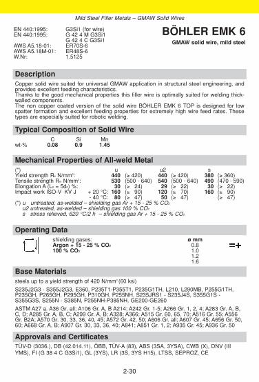
DescriptionCopper solid wire suited for universal GMAW application in structural steel engineering, andprovides excellent feeding characteristics.Thanks to the good mechanical properties this filler wire is optimally suited for welding thick-walled components.The non copper coated version of the solid wire BÖHLER EMK 6 TOP is designed for lowspatter formation and excellent feeding properties for extremely high wire feed rates. Thesetypes are especially suited for robotic welding.
Approvals and CertificatesTÜV-D (3036.), DB (42.014.11), ÖBB, TÜV-A (83), ABS (3SA, 3YSA), CWB (X), DNV (IIIYMS), FI (G 38 4 C G3Si1), GL (3YS), LR (3S, 3YS H15), LTSS, SEPROZ, CE
Base Materialssteels up to a yield strength of 420 N/mm2 (60 ksi)
S235J2G3 - S355J2G3, E360, P235T1-P355T1, P235G1TH, L210, L290MB, P255G1TH,P235GH, P265GH, P295GH, P310GH, P255NH, S235JRS1 - S235J4S, S355G1S -S355G3S, S255N - S385N, P255NH-P385NH, GE200-GE260
ASTM A27 a. A36 Gr. all; A106 Gr. A, B A214; A242 Gr. 1-5; A266 Gr. 1, 2, 4; A283 Gr. A, B,C, D; A285 Gr. A, B, C; A299 Gr. A, B; A328; A366; A515 Gr. 60, 65, 70; A516 Gr. 55; A556Gr. B2A; A570 Gr. 30, 33, 36, 40, 45; A572 Gr. 42, 50; A606 Gr. all; A607 Gr. 45; A656 Gr. 50,60; A668 Gr. A, B; A907 Gr. 30, 33, 36, 40; A841; A851 Gr. 1, 2; A935 Gr. 45; A936 Gr. 50
Operating Datashielding gases: ø mmArgon + 15 - 25 % CO2 0.8100 % CO2 1.0
1.21.6
Mechanical Properties of All-weld Metal(*) u u2 sYield strength Re N/mm2: 440 (≥ 420) 440 (≥ 420) 380 (≥ 360)Tensile strength Rm N/mm2: 530 (500 - 640) 540 (500 - 640) 490 (470 - 590)Elongation A (L0 = 5d0) %: 30 (≥ 324) 29 (≥ 322) 30 (≥ 322)Impact work ISO-V KV J + 20 °C: 160 (≥ 390) 120 (≥ 370) 160 (≥ 390)
- 40 °C: 80 (≥ 347) 50 (≥ 347) (≥ 347)(*) u untreated, as-welded – shielding gas Ar + 15 - 25 % CO2
u2 untreated, as-welded – shielding gas 100 % CO2
s stress relieved, 620 °C/2 h – shielding gas Ar + 15 - 25 % CO2
Typical Composition of Solid WireC Si Mn
wt-% 0.08 0.9 1.45
EN 440:1995: G3Si1 (for wire)EN 440:1995: G 42 4 M G3Si1
G 42 4 C G3Si1AWS A5.18-01: ER70S-6 AWS A5.18M-01: ER48S-6W.Nr: 1.5125
BÖHLER EMK 6GMAW solid wire, mild steel
2-30
Mild Steel Filler Metals – GMAW Solid Wires

DescriptionCopper solid wire used for GMAW of structural components with increased strength requirements.
BÖHLER EMK 7 is designed for semi-automatic and robotic welding and provides excellentfeeding characteristics.
Approvals and CertificatesTÜV-D (3037.), DB (42.014.12 - 20.014.13), ÖBB, CE
Base Materialssteels up to a yield strength of 460 N/mm2 (67 ksi)
S235J2G3 - S355J2G3, E360, P235T1-P355T1, P235G1TH, P255G1TH, P235GH, P265GH,P295GH, P310GH, P255NH, S235JRS1 - S235J4S, S355G1S - S355G3S, S255N - S460N,P255NH-P460NH, GE200-GE260
ASTM A27 a. A36 Gr. all; A106 Gr. A, B A214; A242 Gr. 1-5; A266 Gr. 1, 2, 4; A283 Gr. A, B,C, D; A285 Gr. A, B, C; A299 Gr. A, B; A328; A366; A515 Gr. 60, 65, 70; A516 Gr. 55; A556Gr. B2A; A570 Gr. 30, 33, 36, 40, 45; A572 Gr. 42, 50; A606 Gr. all; A607 Gr. 45; A656 Gr. 50,60; A668 Gr. A, B; A907 Gr. 30, 33, 36, 40; A841; A851 Gr. 1, 2; A935 Gr. 45; A936 Gr. 50
Operating Datashielding gases: ø mmArgon + 15 - 25 % CO2 1.0100 % CO2 1.2
Mechanical Properties of All-weld Metal(*) u u1 sYield strength Re N/mm2: 480 (≥ 460) 470 (≥ 460) 420Tensile strength Rm N/mm2: 590 (530 - 680) 580 (530 - 680) 540Elongation A (L0 = 5d0) %: 26 (≥ 322) 29 (≥ 322) 28Impact work ISO-V KV J + 20 °C: 120 (≥ 380) 110 (≥ 370) 130
- 40 °C: (≥ 347) 65(*) u untreated, as-welded – shielding gas Ar + 15 - 25 % CO2
u1 untreated, as-welded – shielding gas 100 % CO2
s stress relieved, 600 °C/2 h – shielding gas Ar + 15 - 25 % CO2
Typical Composition of Solid WireC Si Mn
wt-% 0.10 0.9 1.75
EN 440:1995: G4Si1 (for wire)EN 440:1995: G 46 4 M G4Si1
G 46 4 C G4Si1AWS A5.18-01: ER70S-6 AWS A5.18M-01: ER48S-6W.Nr: 1.5130
BÖHLER EMK 7GMAW solid wire, mild steel
2-31
Mild Steel Filler Metals – GMAW Solid Wires

DescriptionCopper solid wire used for GMAW of structural components with increased strength require-ments and is optimally suited for welding thick-walled components.BÖHLER EMK 8 is designed for semi-automatic and robotic welding and provides excellentfeeding characteristics.For the T.I.M.E.-process the type BÖHLER EMK 8-T is recommended (ø1.2 mm), and isespecially suited for robotic welding.
Approvals and CertificatesTÜV-D (3038.), DB (42.014.05), ÖBB, ABS (3SA, 3YSA), DNV (III YMS), GL (3YS), LR (3S, 3YS H15), SEPROZ, CE
Base Materialssteels up to a yield strength of 460 N/mm2 (67 ksi)
S235J2G3 - S355J2G3, E360, P235T1-P355T1, P235G1TH, P255G1TH, P235GH, P265GH,P295GH, P310GH, P255NH, S235JRS1 - S235J4S, S355G1S - S355G3S, S255N - S460N,P255NH-P460NH, GE200-GE260
ASTM A27 a. A36 Gr. all; A106 Gr. A, B A214; A 242 Gr. 1-5; A266 Gr. 1, 2, 4; A283 Gr. A, B,C, D; A285 Gr. A, B, C; A299 Gr. A, B; A328; A366; A515 Gr. 60, 65, 70; A516 Gr. 55; A556Gr. B2A; A570 Gr. 30, 33, 36, 40, 45; A572 Gr. 42, 50; A606 Gr. all; A607 Gr. 45; A656 Gr. 50,60; A668 Gr. A, B; A907 Gr. 30, 33, 36, 40; A841; A851 Gr. 1, 2; A935 Gr. 45; A936 Gr. 50
Operating Datashielding gases: ø mmArgon + 15 - 25 % CO2 0.8100 % CO2 1.0
1.2
Mechanical Properties of All-weld Metal(*) u u1 sYield strength Re N/mm2: 470 (≥ 460) 470 (≥ 460) 410Tensile strength Rm N/mm2: 600 (530 - 680) 580 (530 - 680) 540Elongation A (L0 = 5d0) %: 26 (≥ 322) 29 (≥ 322) 28Impact work ISO-V KV J + 20 °C: 120 (≥ 380) 110 (≥ 370) 130
- 40 °C: 50 (≥ 347) 50 (≥ 347) 70(*) u untreated, as-welded – shielding gas Ar + 15 - 25 % CO2
u1 untreated, as-welded – shielding gas 100 % CO2
s stress relieved, 600 °C/2 h – shielding gas Ar + 15 - 25 % CO2
Typical Composition of Solid WireC Si Mn
wt-% 0.11 1.0 1.8
EN 440:1995: G4Si1 (for wire)EN 440:1995: G 46 4 M G4Si1
G 46 4 C G4Si1AWS A5.18-01: ER70S-6 AWS A5.18M-01: ER48S-6W.Nr: 1.5130
BÖHLER EMK 8GMAW solid wire, mild steel
2-32
Mild Steel Filler Metals – GMAW solid wires

DescriptionAll position rutile flux cored wire with fast freezing slag system. User friendly welding characte-ristics in all positions with one wire dia. 1.2 mm and same parameter setting. Excellent mecha-nical properties, easy slag removal, low spatter loss, smooth, finely rippled bead surface, highX-ray safety. The product performs to the highest productivity with significant savings in time and economi-cal aspects when used for positional welding.
Approvals and CertificatesTÜV-D (09929.), ABS (3SA, 3YSA (CO2,M21)), BV (X), DNV (III YMS(H10) [CO2, M21]), GL(3YH10S (C1), 3YS (M21), LR (DXVudO; BF; 3S; 3YS; H15; NA), CRS (M21, C1, 3YH10S)
Base Materialssteels up to a yield strength of 460 N/mm2 (67 ksi)
S235J2G3 - S355J2G3, GE200, GE240, GE260, S235JRS1 - S235J2S, AH, DH, EH, S255N- S355N, P235GH, P265GH, S255N, P295GH, S235G2T, S255GT, S355GT, L210 - L360NB, P235G1TH, P255G1TH
ASTM A27 a. A36 Gr. all; A106 Gr. A, B A214; A 242 Gr. 1-5; A266 Gr. 1, 2, 4; A283 Gr. A, B,C, D; A285 Gr. A, B, C; A299 Gr. A, B; A328; A366; A515 Gr. 60, 65, 70; A516 Gr. 55; A556Gr. B2A; A570 Gr. 30, 33, 36, 40, 45; A572 Gr. 42, 50; A606 G907 Gr. 30, 33, 36, 40; Gr. all;A607 Gr. 45; A656 Gr. 50, 60; A668 Gr. A, B; AA841; A851 Gr. 1, 2; A935 Gr. 45; A936 Gr. 50;API 5L X42 - X56
Operating Datare-drying: possible 150 °C / 24 h ø mmshielding gases: 1.2Argon + 15 - 25 % CO2 1.6100 % CO2
Welding with standard GMAW-facilities possible.
Mechanical Properties of All-weld Metal(*) u u1 Yield strength Re N/mm2: 490 (≥ 460) 470 (≥ 420)Tensile strength Rm N/mm2: 580 (550 - 640) 540 (510 - 640)Elongation A (L0 = 5d0) %: 26 (≥ 322) 27 (≥ 322)Impact work ISO-V KV J + 20 °C: 180 (≥ 130) 170 (≥ 120)
- 20 °C: 130 (≥ 354) 120 (≥ 354)-40 °C: 90 80
(*) u untreated, as-welded – shielding gas Ar + 15 - 25 % CO2
u1 untreated, as-welded – shielding gas 100 % CO2
Typical Composition of All-weld MetalC Si Mn Ti
wt-% 0.06 0.5 1.2 +
EN 758:1997: T 46 2 P M 1 H10T 42 2 P C 1 H5
AWS A5.20-95: E71T-1H4E71T-1MH8
BÖHLER Ti 52-FDGMAW rutile flux cored wire, mild steel
2-33
Mild Steel Filler Metals – GMAW Flux-cored Wires

2-34
DescriptionRutile flux cored wire with fast freezing slag. Excellent welding characteristics in all positions.Very good mechanical properties, easy slag removability, low spatter level, smooth and wellshaped beads with x-ray-quality. Higher welding current (230 A) is applicable in out-of-positionwelding, which results in cost reduction due to higher productivity and less time for postweldcleaning. Particularly suited for welding prime coated plates in shipbuilding, steel- and bridgeconstructions.
Approvals and CertificatesTÜV-D (09969.), DB (42.014.03), ÖBB, GL (3YH10S)
Base MaterialsSteels up to a yield strength of 460 N/mm2 (67 ksi)
S235 - S355J4G3, GE200, GE240, GE260, S235JRS1 - S235J4S, AH, DH, EH, S255N -S355N, P235GH, P265GH, S255N, P295GH, S235G2T, S255GT, S355GT, L210 - L360NB, X 42-X 60, P235G1TH, P255G1THASTM A27 u. A36 Gr. all; A106 Gr. A, B A214; A 242 Gr.1-5; A266 Gr. 1, 2, 4; A283 Gr. A, B,C, D; A285 Gr. A, B, C; A299 Gr. A, B; A328; A366; A515 Gr. 60, 65, 70; A516 Gr. 55; A556Gr. B2A; A570 Gr. 30, 33, 36, 40, 45; A572 Gr. 42, 50; A606 G907 Gr. 30, 33, 36, 40; Gr. all;A607 Gr. 45; A656 Gr. 50, 60; A668 Gr. A, B; AA841; A851 Gr. 1, 2; A935 Gr.45; A936 Gr. 50;API 5L X42-X60
Typical Composition of All-weld MetalC Si Mn Ti
Gew-% 0.05 0.5 1.3 +
EN 758: T 46 4 P M 1 H10T 42 2 P C 1 H5
AWS A5.20-95: E71T-1J H8E71T-1MJ H8
BÖHLER Ti 52 W-FD Flux rutile cored wire, mild steel
Operating Datare-drying: possible 150 °C / 24 h ø mmshielding gases: 1.2Argon +15-25 % CO2 1.6100 % CO2
welding with standard GMAW-facilities possible.
Mechanical Properties of All-weld Metal(*) u u1 syield strength Re N/mm2: 520 (≥ 460) 480 (≥ 420) (≥ 460)tensile strength Rm N/mm2: 580 (550-640) 540 (530-630) (550-640)elongation A (L0=5d0) %: 24 (≥ 022) 25 (≥ 024) (≥ 022)impact work ISO-V KV J +20 °C: 140 (≥ 130) 130 (≥ 100) (≥ 120)
-20 °C: 110 (≥ 054) 100 (≥ 054)-40 °C: 95 (≥ 054)
(*) u untreated, as-welded – shielding gas Ar + 15-25 % CO2
u1 untreated, as-welded – shielding gas 100 % CO2
s stress relieved 580 °C/2 h/furnace down to 300 °C/air
Mild Steel Filler Metals – GMAW Flux-cored Wires

DescriptionMetal cored high-efficiency wire for semi-automatic and fully automatic joint welding of unal-loyed and fine-grained constructional steels and service temperatures from -40 °C to +450 °C. Very high metal recovery between 93 and 97 % and deposition rate up to 9 kg/hr. Steady sprayarc-like droplet transfer with minimal spatter formation. Good penetration, high resistance toporosity, good wetting behaviour as well as low hydrogen contents (< 5 ml/100 g deposit) arefurther quality features of this flux cored wire. Minimum oxide residues permit the welding of multi passes without the need for inter-runcleaning. Ideal for horizontal and flat fillet welds. Compared to solid wires 20 % higher produc-tivity can be achieved.
Approvals and CertificatesTÜV-D (09928.), DB (42.014.29), ÖBB, ABS (4SA-4YSAH5), DNV (requested), GL (4YH5S),LR (DXVudO; BF, 3S; 4YS; H5)
Base Materialssteels up to a yield strength of 460 N/mm2 (67 ksi)
S235J2G3 - S355J2G3, GE200, GE240, GE260, S235JRS1 - S235J4S, AH, DH, EH, S255N- S380N, P235GH, P265GH, S255N, P295GH, S235G2T, S255GT, S355GT, L210 - L360NB, P235G1TH, P255G1TH
ASTM A27 a. A36 Gr. all; A106 Gr. A, B A214; A 242 Gr. 1-5; A266 Gr. 1, 2, 4; A283 Gr. A, B,C, D; A285 Gr. A, B, C; A299 Gr. A, B; A328; A366; A515 Gr. 60, 65, 70; A516 Gr. 55; A556Gr. B2A; A570 Gr. 30, 33, 36, 40, 45; A572 Gr. 42, 50; A606 Gr. all; A607 Gr. 45; A656 Gr.50, 60; A668 Gr. A, B; A907 Gr. 30, 33, 36, 40; A841; A851 Gr. 1, 2; A935 Gr. 45; A936 Gr. 50;API 5L X42 - X60
Operating Datare-drying: not necessary ø mmshielding gases: 1.2Argon + 15 - 25 % CO2 1.6Welding with standard GMAW-facilities possible.
Mechanical Properties of All-weld Metal(*) uYield strength Re N/mm2: 490 (≥ 460)Tensile strength Rm N/mm2: 610 (550 - 650)Elongation A (L0 = 5d0) %: 27 (≥ 324)Impact work ISO-V KV J + 20 °C: 130 (≥ 100)
- 40 °C: 90 (≥ 347)(*) u untreated, as-welded – shielding gas Ar + 15 - 25 % CO2
Typical Composition of All-weld MetalC Si Mn
wt-% 0.07 0.7 1.5
EN 758:1997: T 46 4 M M 2 H5AWS A5.18-01: E70C-6MH4AWS A5.18M-01: E48C-6MH4
BÖHLER HL 51-FDGMAW metal cored wire, mild steel
2-35
Mild Steel Filler Metals – GMAW Flux-cored Wires

2-36
DescriptionMetal cored high efficiency wire for fully automatic and semi-automatic joint welding of unalloy-ed and fine-grained constructional steels. The special filling composition permits very highmetal recovery between 93 and 97 % and deposition rates of up to 8 kg/hr. Smooth spray trans-fer, minimum spattering, a very good bead profile and excellent wetting behaviour are the cha-racteristics of HL 53-FD. Another advantage is minimum oxide formation, which allows multi-passwelding without deslagging. The hydrogen content of the weld deposit is ≤ 5 ml/100 g deposit.HL 53-FD is suitable for fillet welds and butt welds of standard constructional steels as well asfor fine-grained steels in structural steel engineering. The service temperature range is -50 /+450 °C.
Approvals and CertificatesTÜV-D (09968.)
Base MaterialsSteels with yield strength of 420 N/mm2 (60 ksi)S235 - S355J2G3, GE200, GE240, GE260, S235JRS1 - S235J4S, AH, DH, EH, S255N -S380N, P235GH, P265GH, S255N, P295GH, S235G2T, S255GT, S355GT, L210 - L360NB, X 42-X 60, P235G1TH, P255G1TH
ASTM A27 u. A36 Gr. all; A106 Gr. A, B A214; A242 Gr.1-5; A266 Gr. 1, 2, 4; A283 Gr. A, B,C, D; A285 Gr. A, B, C; A299 Gr. A, B; A328; A366; A515 Gr. 60, 65, 70; A516 Gr. 55; A556Gr. B2A; A570 Gr. 30, 33, 36, 40, 45 572 Gr. 42, 50; A606 Gr. all A607 Gr. 45; A656 Gr. 50,60; A668 Gr. A, B; A907 Gr. 30, 33, 36, 40; A841; A851 Gr. 1, 2; A935 Gr.45; A936 Gr. 50;API 5L X42-X60
Operating DataRebaking: not necessary ø mmshielding gas: 1.2Argon +15-25 % CO2 1.6Welding with standard welding facilities.
Mechanical Properties of All-weld Metal(*) u syield strength Re N/mm2: ≥ 420 470tensile strength Rm N/mm2: 520-620 530elongation A (L0 = 5d0) %: ≥ 022 27impact work ISO-V AV J +20 °C: ≥ 100 190
-50 °C: (≥ 047)
(*) u untreated, as welded – shielding gas Ar +15-20 % CO2
s stress relieved, 600°C/2 h – shielding gas Ar +15-20 % CO2
Typical Composition of All-weld MetalC Si Mn Ni
wt-% 0.06 0.5 1.2 0.9
EN 758: T 42 5 Z M M 2 H5AWS A5.18-01: E 70 C-GM H4AWS A5.18M-01: E 48 C-GM H4
BÖHLER HL 53-FDGMAW metal cored wire, mild steel
Mild Steel Filler Metals – GMAW Flux-cored Wires

DescriptionUniversally applicable for constructional steels and fine grained steels, e.g. in shipbuilding,structural steel work, and pressure vessel fabrication. The flux reacts metallurgically Mn-neu-tral. The sub-arc wire/flux combination produces very good low temperature impact propertiesdown to -60 °C. Excellent slag detachability, smooth beads, good wetting and low hydrogencontents (HD ≤ 5 ml/100 g) are further important features. The combination is ideally suited formulti-pass welding of thick plates.For information regarding the sub-arc welding flux BÖHLER BB 24 see our detailed data sheet.
Approvals and CertificatesTÜV-D (7808.). Wire: TÜV-D (02603.), KTA 1408.1 (8058.00), DB (52.014.03), ÖBB, TÜV-A (391), SEPROZ, CE
Base Materialssteels up to a yield strength of 400 N/mm2 (56 ksi)S235JR - S335JR, S235J2G3 - S335J2G3, P235T1 - P335T1, P235T2 - P355T2, P235GH,P265GH, S255N, P295GH, P310GH, S235JRS1 - S235J4S, S255N - S380NASTM A36 Gr. all; A 106 Gr. A, B A214; A 242 Gr. 1-5; A266 Gr. 1, 2, 4; A283 Gr. A, B, C, D;A285 Gr. A, B, C; A299 Gr. A, B; A328; A366; A515 Gr. 60, 65, 70; A516 Gr. 55; A556 Gr.B2A; A570 Gr. 30, 33, 36, 40, 45; A572 Gr. 42, 50; A606 Gr. all; A607 Gr. 45; A656 Gr. 50,60; A668 Gr. A, B; A907 Gr. 30, 33, 36, 40; A841; A851 Gr. 1, 2; A935 Gr. 45; A936 Gr. 50;API 5L X42 - X52
Operating Datare-drying of sub-arc flux: ø mm300 - 350 °C, 2 h - 10 h 2.0 3.2
2.5 4.03.0
Mechanical Properties of All-weld Metal(*) uYield strength Re N/mm2: 440 (≥ 400)Tensile strength Rm N/mm2: 520 (≥ 500)Elongation A (L0 = 5d0) %: 33 (≥ 326)Impact work ISO-V KV J + 20 °C: 185 (≥ 160)
± 0 °C: 180 (≥ 140)- 20 °C: 170 (≥ 100)- 60 °C: 140 (≥ 047)
(*) u untreated, as-welded
Typical Composition of Solid Wire and All-weld MetalC Si Mn
SAW wire wt-% 0.11 0.12 1.1all-weld metal % 0.07 0.25 1.2
SAW solid wire:EN 756:2004: S2AWS A5.17-97: EM12K
sub-arc flux:EN 760:1996: SA FB 1 65 DC H5
wire/flux-combination:EN 756:2004: S 38 6 FB S2AWS A5.17-97: F7A8-EM12K (F6P8-EM12K)AWS A5.17M-97: F48A6-EM12K (F43P6-EM12K)
BÖHLER EMS 2 // BB 24SAW wire/flux-combination, mild steel
2-37
Mild Steel Filler Metals – SAW Wire/Flux-Combinations

DescriptionUniversally applicable for constructional steels and fine grained steels, e.g. in shipbuilding,structural steel work, and pressure vessel fabrication. The flux is active and shows some pick-up of silicon and manganese. The sub-arc wire/flux combination produces higher strengthvalues with very good low temperature impact properties down to -40 °C.For information regarding the sub-arc welding flux BÖHLER BB 25 see our detailed data sheet.
Approvals and CertificatesTÜV-A (621). Wire: TÜV-D (02603.), KTA 1408.1 (8058.00), DB (52.014.03), ÖBB, TÜV-A (391), SEPROZ, CE
Base Materialssteels up to a yield strength of 420 N/mm2 (60 ksi)
S235J2G3-S355J2G3, GE200, GE240, GE260, S235JRS1-S235J4S, AH, DH, EH, S255N-S380N, P235GH, P265GH, S255N, P295GH, S235G2T, S255GT, S355GT, L210-L360NB,P235G1TH, P255G1TH
ASTM A36 Gr. all; A 106 Gr. A, B A214; A 242 Gr. 1-5; A266 Gr. 1, 2, 4; A283 Gr. A, B, C, D;A285 Gr. A, B, C; A299 Gr. A, B; A328; A366; A515 Gr. 60, 65, 70; A516 Gr. 55; A556 Gr.B2A; A570 Gr. 30, 33, 36, 40, 45; A572 Gr. 42, 50; A606 Gr. all; A607 Gr. 45; A656 Gr. 50,60; A668 Gr. A, B; A907 Gr. 30, 33, 36, 40; A841; A851 Gr. 1, 2; A935 Gr. 45; A936 Gr. 50;API 5L X42 - X56
Operating Datare-drying of sub-arc flux: ø mm300 - 350 °C, 2 h - 10 h 2.0 3.2
2.5 4.03.0
Mechanical Properties of All-weld Metal(*) uYield strength Re N/mm2: 450 (≥ 420)Tensile strength Rm N/mm2: 530 (≥ 500)Elongation A (L0 = 5d0) %: 28 (≥ 322)Impact work ISO-V KV J + 20 °C: 180
± 0 °C: 130- 20 °C: 100- 40 °C: 90 (≥ 347)
(*) u untreated, as-welded
Typical Composition of Solid Wire and All-weld MetalC Si Mn
SAW wire wt-% 0.11 0.12 1.1all-weld metal % 0.07 0.40 1.45
SAW solid wire:EN 756:2004: S2AWS A5.17-97: EM12K
sub-arc flux:EN 760:1996: SA FB 1 68 AC H5
wire/flux-combination:EN 756:2004: S 42 4 FB S2AWS A5.17-97: F7A4-EM12KAWS A5.17M-97: F48A4-EM12K
BÖHLER EMS 2 // BB 25SAW wire/flux-combination, mild steel
2-38
Mild Steel Filler Metals – SAW Wire/Flux-Combinations

DescriptionUniversally applicable for high-speed welding of constructional steels and fine grained steels,e.g. in shipbuilding, structural steel work, and pressure vessel fabrication.The sub-arc wire/flux combination produces good impact properties at 0 °C and higher strengthproperties. Good wetting characteristics with fine rippled bead appearance at high travel speed.For information regarding the sub-arc welding flux BÖHLER BB 33 M see our detailed datasheet.
Approvals and CertificatesTÜV-D (5685.), TÜV-A (617)Wire: TÜV-D (02603.), KTA 1408.1 (8058.00), DB (52.014.03), ÖBB, TÜV-A (391), SEPROZ,CE
Base Materialssteels up to a yield strength of 460 N/mm2 (67 ksi)
S235J0G3-S355J0G3, GE200, GE240, GE260, S235JRS1-S235J0S, AH, DH, EH, S255N-S380N, P235GH, P265GH, S255N, P295GH, S235G2T, S255GT, S355GT, L210-L360NB,P235G0TH, P255G0TH
ASTM A36 Gr. all; A 106 Gr. A, B A214; A 242 Gr. 1-5; A266 Gr. 1, 2, 4; A283 Gr. A, B, C, D;A285 Gr. A, B, C; A299 Gr. A, B; A328; A366; A515 Gr. 60, 65, 70; A516 Gr. 55; A556 Gr.B2A; A570 Gr. 30, 33, 36, 40, 45; A572 Gr. 42, 50; A606 Gr. all; A607 Gr. 45; A656 Gr. 50,60; A668 Gr. A, B; A907 Gr. 30, 33, 36, 40; A841; A851 Gr. 1, 2; A935 Gr. 45; A936 Gr. 50;API 5L X42-X60
Operating Datare-drying of sub-arc flux: ø mm275 - 325 °C, 2 h - 4 h 2.0 3.2
2.5 4.0 3.0
Mechanical Properties of All-weld Metal(*) uYield strength Re N/mm2: 540 (≥ 460) Tensile strength Rm N/mm2: 620 (≥ 520)Elongation A (L0 = 5d0) %: 29 (≥ 322)Impact work ISO-V KV J + 20 °C: 70 (≥ 360)
± 0 °C: 50 (≥ 347)- 20 °C: 40
(*) u untreated, as-welded
Typical Composition of Solid Wire and All-weld MetalC Si Mn
SAW wire wt-% 0.11 0.12 1.1all-weld metal % 0.08 0.70 1.3
SAW solid wire:EN 756:2004: S2AWS A5.17-97: EM12K
sub-arc flux:EN 760:1996: SA AR 1 97 AC SKM
wire/flux-combination:EN 756:2004: S 46 0 AR S2AWS A5.17-97: F7AZ-EM12KAWS A5.17M-97: F48A0-EM12K
BÖHLER EMS 2 // BB 33 MSAW wire/flux-combination, mild steel
2-39
Mild Steel Filler Metals – SAW Wire/Flux-Combinations

DescriptionBÖHLER BF 16 is a fused acid Si and Mn alloying flux with high current carrying capacity onboth AC and DC. In combination with the wire BÖHLER EMS 2 it gives fine performance inuniversal applications for mild steel constructural work of thinner walled components.For information regarding the sub-arc welding flux BÖHLER BF 16 see our detailed data sheet.
Approvals and CertificatesTÜV-A (6)Wire: TÜV-D (02603.), KTA 1408.1 (8058.00), DB (52.014.03), ÖBB, TÜV-A (391), SEPROZ,CE
Base Materialssteels up to a yield strength of 380 N/mm2 (50 ksi)
S235JR-S335JR, S235J0G3-S335J0G3, P235T1-P335T1, P235T2- P355T2, P235GH,P265GH, S255N, P295GH, P310GH, S235JRS1-S235J0S, S255N-S380N
ASTM A36 Gr. all; A 106 Gr. A, B A214; A 242 Gr. 1-5; A266 Gr. 1, 2, 4; A283 Gr. A, B, C, D;A285 Gr. A, B, C; A299 Gr. A, B; A328; A366; A515 Gr. 60, 65, 70; A516 Gr. 55; A556 Gr.B2A; A570 Gr. 30, 33, 36, 40, 45; A572 Gr. 42, 50; A606 Gr. all; A607 Gr. 45; A656 Gr. 50,60; A668 Gr. A, B; A907 Gr. 30, 33, 36, 40; A841; A851 Gr. 1, 2; A935 Gr. 45; A936 Gr. 50;API 5L X42 - X52
Operating Datare-drying of sub-arc flux: ø mm250 - 350 °C, 1 h - 10 h 2.0 3.2
2.5 4.0 3.0
Mechanical Properties of All-weld Metal(*) uYield strength Re N/mm2: 400 (≥ 380)Tensile strength Rm N/mm2: 500 (≥ 470)Elongation A (L0 = 5d0) %: 29 (≥ 322)Impact work ISO-V KV J + 20 °C: 90 (≥ 370)
± 0 °C: 60 (≥ 347)- 20 °C: 40 (≥ 327)
(*) u untreated, as-welded
Typical Composition of Solid Wire and All-weld MetalC Si Mn
SAW wire wt-% 0.11 0.12 1.1all-weld metal % 0.04 0.50 1.3
SAW solid wire:EN 756:2004: S2AWS A5.17-97: EM12K
sub-arc flux:EN 760:1996: SF MS 1 78 AC M
wire/flux-combination:EN 756:2004: S 38 0 MS S2AWS A5.17-97: F6A0-EM12KAWS A5.17M-97: F43A2-EM12K
BÖHLER EMS 2 // BF 16SAW wire/flux-combination, mild steel
2-40
Mild Steel Filler Metals – SAW Wire/Flux-Combinations

DescriptionUniversally applicable, e.g. in shipbuilding, structural steel work, and pressure vessel fabrication.The flux reacts metallurgically Mn-neutral. The sub-arc wire/flux combination produces higher strength values with very good low tempe-rature impact properties. Excellent slag detachability, smooth beads, good wetting and lowhydrogen contents (≤ 5 ml/100 g) are further important features. The combination is ideally suited for multi-pass welding of thick plates.The deposit produces very good low temperature impact properties down to -40 °C.For information regarding the sub-arc welding flux BÖHLER BB 24 see our detailed data sheet.
Approvals and CertificatesTÜV-D (7811.). Wire: TÜV-D (02603.), KTA 1408.1 (8058.00), DB (52.014.04), ÖBB, TÜV-A(391), SEPROZ, CE
Base Materialssteels up to a yield strength of 420 N/mm2 (60 ksi)
S235J2G3 - S355J2G3, GE200, GE240, GE260, S235JRS1 - S235J4S, AH, DH, EH, S255N- S380N, P235GH, P265GH, S255N, P295GH, S235G2T, S255GT, S355GT, L210 - L360NB,P235G1TH, P255G1TH
ASTM A36 Gr. all; A 106 Gr. A, B A214; A 242 Gr. 1-5; A266 Gr. 1, 2, 4; A283 Gr. A, B, C, D;A285 Gr. A, B, C; A299 Gr. A, B; A328; A366; A515 Gr. 60, 65, 70; A516 Gr. 55; A556 Gr.B2A; A570 Gr. 30, 33, 36, 40, 45; A572 Gr. 42, 50; A606 Gr. all; A607 Gr. 45; A656 Gr. 50,60; A668 Gr. A, B; A907 Gr. 30, 33, 36, 40; A841; A851 Gr. 1, 2; A935 Gr. 45; A936 Gr. 50;API 5L X42 - X56
Operating Datare-drying of sub-arc flux: ø mm300 - 350 °C, 2 h - 10 h 4.0
Mechanical Properties of All-weld Metal(*) uYield strength Re N/mm2: (≥ 420)Tensile strength Rm N/mm2: (≥ 510)Elongation A (L0 = 5d0) %: (≥ 324)Impact work ISO-V KV J + 20 °C: (≥ 130)
± 0 °C: (≥ 100)- 20 °C: (≥ 370)- 40 °C: (≥ 347)
(*) u untreated, as-welded
Typical Composition of Solid Wire and All-weld MetalC Si Mn
SAW wire wt-% 0.12 0.1 1.5all-weld metal % 0.08 0.25 1.5
SAW solid wire:EN 756:2004: S3AWS A5.17-97: EH10K
sub-arc flux:EN 760:1996: SA FB 1 65 DC H5
wire/flux-combination:EN 756:2004: S 42 4 FB S3AWS A5.17-97: F7A4-EH10K (F7P8-EH10K)AWS A5.17M-97: F48A4-EH10K (F48P6-EH10K)
BÖHLER EMS 3 // BB 24SAW wire/flux-combination, mild steel
2-41
Mild Steel Filler Metals – SAW Wire/Flux-Combinations

DescriptionUniversally applicable, e.g. in shipbuilding, structural steel work, and pressure vessel fabrication.The flux reacts metallurgically active and shows some pick-up of silicon and manganese.The sub-arc wire/flux combination produces higher strength values with very good low tempe-rature impact properties down to -30 °C.For information regarding the sub-arc welding flux BÖHLER BB 25 see our detailed data sheet.
Approvals and CertificatesWire: TÜV-D (02603.), KTA 1408.1 (8058.00), DB (52.014.04), ÖBB, TÜV-A (391), SEPROZ,CE
Base Materialssteels up to a yield strength of 420 N/mm2 (60 ksi)
S235J2G3-S355J2G3, GE200, GE240, GE260, S235JRS1-S235J3S, AH, DH, EH, S255N-S380N, P235GH, P265GH, S255N, P295GH, S235G2T, S255GT, S355GT, L210-L360NB,P235G1TH, P255G1TH
ASTM A36 Gr. all; A 106 Gr. A, B A214; A 242 Gr. 1-5; A266 Gr. 1, 2, 4; A283 Gr. A, B, C, D;A285 Gr. A, B, C; A299 Gr. A, B; A328; A366; A515 Gr. 60, 65, 70; A516 Gr. 55; A556 Gr.B2A; A570 Gr. 30, 33, 36, 40, 45, A572 Gr. 42, 50; A606 Gr. all; A607 Gr. 45; A656 Gr. 50,60; A668 Gr. A, B; A907 Gr. 30, 33, 36, 40; A841; A851 Gr. 1, 2; A935 Gr. 45; A936 Gr. 50;API 5L X42 - X56
Operating Datare-drying of sub-arc flux: ø mm300 - 350 °C, 2 h - 10 h 4.0
Mechanical Properties of All-weld Metal(*) uYield strength Re N/mm2: 520 (≥ 420)Tensile strength Rm N/mm2: 600 (≥ 530)Elongation A (L0 = 5d0) %: 23 (≥ 320)Impact work ISO-V KV J + 20 °C: 140
- 20 °C: 70- 30 °C: 50 (≥ 347)
(*) u untreated, as-welded
Typical Composition of Solid Wire and All-weld MetalC Si Mn
SAW wire wt-% 0.12 0.1 1.5all-weld metal % 0.06 0.35 1.7
SAW solid wire:EN 756:2004: S3AWS A5.17-97: EH10K
sub-arc flux:EN 760:1996: SA FB 1 68 AC H5
wire/flux-combination:EN 756:2004: S 42 3 FB S3AWS A5.17-97: F7A3-EH10KAWS A5.17M-97: F48A2-EH10K
BÖHLER EMS 3 // BB 25SAW wire/flux-combination, mild steel
2-42
Mild Steel Filler Metals – SAW Wire/Flux-Combinations

DescriptionUniversally applicable for high-speed welding of constructional steels and fine grained steels,e.g. in shipbuilding, structural steel work, and pressure vessel fabrication.The sub-arc wire/flux combination produces good impact properties at 0 °C and higher strengthproperties. Good wetting characteristics with fine rippled bead appearance at high travel speed. For information regarding the sub-arc welding flux BÖHLER BB 33 M see our detailed datasheet.
ApprovalsWire: TÜV-D (02603.), KTA 1408.1 (8058.00), DB (52.014.04), ÖBB, TÜV-A (391), SEPROZ,CE
Base Materialssteels up to a yield strength of 500 N/mm2 (72 ksi)
S235J0G3 - S355J0G3, GE200, GE240, GE260, S235JRS1 - S235J0S, AH, DH, EH, S255N- S380N, P235GH, P265GH, S255N, P295GH, S235G2T, S255GT, S355GT, L210 - L360NB,P235G0TH, P255G0TH
ASTM A36 Gr. all; A 106 Gr. A, B A214; A 242 Gr. 1-5; A266 Gr. 1, 2, 4; A283 Gr. A, B, C, D;A285 Gr. A, B, C; A299 Gr. A, B; A328; A366; A515 Gr. 60, 65, 70; A516 Gr. 55; A556 Gr.B2A; A570 Gr. 30, 33, 36, 40, 45, A572 Gr. 42, 50; A606 Gr. all; A607 Gr. 45; A656 Gr. 50,60; A668 Gr. A, B; A907 Gr. 30, 33, 36, 40; A841; A851 Gr. 1, 2; A935 Gr. 45; A936 Gr. 50;API 5L X42-X60
Operating Datare-drying of sub-arc flux: ø mm275 - 325 °C, 2 h - 4 h 4.0
Mechanical Properties of All-weld Metal(*) uYield strength Re N/mm2: 550 (≥ 500)Tensile strength Rm N/mm2: 650 (≥ 560)Elongation A (L0 = 5d0) %: 20 (≥ 318)Impact work ISO-V KV J + 20 °C: 60
± 0 °C: (≥ 347)(*) u untreated, as-welded
Typical Composition of Solid Wire and All-weld MetalC Si Mn
SAW wire wt-% 0.12 0.1 1.5 all-weld metal % 0.08 0.75 1.7
SAW solid wire:EN 756:2004: S3AWS A5.17-97: EH10K
sub-arc flux:EN 760:1996: SA AR 1 97 AC SKM
wire/flux-combination:EN 756:2004: S 50 0 AR S3AWS A5.17-97: F7AZ-EH10K AWS A5.17M-97: F48A0-EH10K
BÖHLER EMS 3 // BB 33 MSAW wire/flux-combination, mild steel
2-43
Mild Steel Filler Metals – SAW Wire/Flux-Combinations

DescriptionUniversally applicable, e.g. in shipbuilding, structural steel work, and pressure vessel fabrication.The wire/flux combination produces higher strength properties. BÖHLER BF 16 is a fused acid Siand Mn alloying flux with high current carrying capacity on both AC and DC. In combination withthe wire BÖHLER EMS 3 it gives fine performance in universal applications for mild steel con-structural work of thinner walled components. The sub-arc wire/flux combination produces good impact properties at 0 °C.For information regarding the sub-arc welding flux BÖHLER BF 16 see our detailed data sheet.
Approvals and CertificatesWire: TÜV-D (02603.), KTA 1408.1 (8058.00), DB (52.014.04), ÖBB, TÜV-A (391), SEPROZ,CE
Base Materialssteels up to a yield strength of 380 N/mm2 (52 ksi)
S235JR - S355JR, S235J0G3 - S355J0G3, P235T1-P355T1, P235T2- P355T2, P235GH,P265GH, S255N, P295GH, P310GH, S235JRS1 - S235J0S, S355N - S420N
ASTM A36 Gr. all; A 106 Gr. A, B A214; A 242 Gr. 1-5; A266 Gr. 1, 2, 4; A283 Gr. A, B, C, D;A285 Gr. A, B, C; A299 Gr. A, B; A328; A366; A515 Gr. 60, 65, 70; A516 Gr. 55; A556 Gr.B2A; A570 Gr. 30, 33, 36, 40, 45, A572 Gr. 42, 50; A606 Gr. all; A607 Gr. 45; A656 Gr. 50,60; A668 Gr. A, B; A907 Gr. 30, 33, 36, 40; A841; A851 Gr. 1, 2; A935 Gr. 45; A936 Gr. 50;API 5L X42 - X52
Operating Datare-drying of sub-arc flux: ø mm250 - 350 °C, 1 h - 10 h: 4.0
Mechanical Properties of All-weld Metal(*) uYield strength Re N/mm2: 410 (≥ 380)Tensile strength Rm N/mm2: 520 (≥ 470)Elongation A (L0 = 5d0) %: 25 (≥ 322)Impact work ISO-V KV J + 20 °C: 70
± 0 °C: 55 (≥ 347)- 20 °C: 45- 30 °C: 40
(*) u untreated, as-welded
Typical Composition of Solid Wire and All-weld MetalC Si Mn
SAW wire wt-% 0.12 0.1 1.5all-weld metal % 0.04 0.45 1.7
SAW solid wire:EN 756:2004: S3AWS A5.17-97: EH10K
sub-arc flux:EN 760:1996: SF MS 1 78 AC M
wire/flux-combination:EN 756:2004: S 38 0 MS S3AWS A5.17-97: F6A0-EH10K AWS A5.17M-97: F43A3-EH10K
BÖHLER EMS 3 // BF 16SAW wire/flux-combination, mild steel
2-44
Mild Steel Filler Metals – SAW Wire/Flux-Combinations
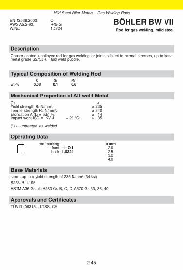
DescriptionCopper coated, unalloyed rod for gas welding for joints subject to normal stresses, up to basemetal grade S275JR. Fluid weld puddle.
Approvals and CertificatesTÜV-D (06315.), LTSS, CE
Base Materialssteels up to a yield strength of 235 N/mm2 (34 ksi)
S235JR, L195
ASTM A36 Gr. all; A283 Gr. B, C, D; A570 Gr. 33, 36, 40
Operating Datarod marking: ø mm
front: O I 2.0back: 1.0324 2.5
3.24.0
Mechanical Properties of All-weld Metal(*) uYield strength Re N/mm2: ≥ 235Tensile strength Rm N/mm2: ≥ 340Elongation A (L0 = 5d0) %: ≥ 314Impact work ISO-V KV J + 20 °C: ≥ 335
(*) u untreated, as-welded
Typical Composition of Welding RodC Si Mn
wt-% 0.08 0.1 0.6
EN 12536:2000: O IAWS A5.2-92: R45-G W.Nr.: 1.0324
BÖHLER BW VIIRod for gas welding, mild steel
2-45
Mild Steel Filler Metals – Gas Welding Rods

DescriptionGas welding rod, nickel alloyed. Easy to operate due to very easy weld pool and slag controland good gap bridging ability.Weld pools are not susceptible to overheating when welded with a too hot flame.
Approvals and CertificatesTÜV-D (02323.), DB (70.014.01), ÖBB, CE
Base Materialssteels up to a yield strength of 275 N/mm2 (40 ksi)
S235JR - S275JR, P275GH, L235 - L290NB
ASTM A36 Gr. all; A283 Gr. B, C, D; A285 Gr. B; A414 Gr.C; A442 Gr.60; A515 Gr. 60; A516Gr. 55, 60; A570 Gr. 33, 36, 40
Operating Datarod marking: ø mm
front: O III 2.0back: 1.6215 2.5
3.0
Mechanical Properties of All-weld Metal(*) uYield strength Re N/mm2: ≥ 275Tensile strength Rm N/mm2: ≥ 410 Elongation A (L0 = 5d0) %: ≥ 314Impact work ISO-V KV J + 20 °C: ≥ 347
(*) u untreated, as-welded
Typical Composition of Welding RodC Si Mn Ni
wt-% 0.10 0.15 1.1 0.45
EN 12536:2000: O IIIAWS A5.2-92: R60-G W.Nr.: 1.6215
BÖHLER BW XIIRod for gas welding, mild steel
2-46
Mild Steel Filler Metals – Gas Welding Rods

2-47
Notes
2-48
Notes

2-49
2.3. Filler Metalsfor Pipeline Welding
ObjectivesThis section provides detailed product information for filler metals that maybe used to weld pipelines. The significance of oil and gas as a source of energy leads to the construc-tion and planning of cross-country pipelines throughout the world. In thiscase new high-strength pipe steels place the highest possible demands onwelding technology. As a result various filler metals have been developedthat can cover all the requirements of individual steel qualities.
◆
Product Information
Welding procedure when using cellulosic electrodesRecommended joint preparation
Wall thicknesses ≤ 20 mm ( ≤ 3/4 inch) Wall thicknesses > 20 mm (> 3/4 inch)
Preheating and interpass temperatures in relation to wall thicknesses
2-50
Contents
OVERVIEW . . . . . . . . . . . . . . . . . . . . . . . . . . . . . . . . . . . . . . . . . . . . . . . .51
SMAW CELLULOSIC ELECTRODES . . . . . . . . . . . . . . . . . . . . . . . . . . .52
SMAW BASIC ELECTRODES . . . . . . . . . . . . . . . . . . . . . . . . . . . . . . . . .58
GMAW SOLID WIRES FOR AUTOMATIC WELDING . . . . . . . . . . . . . . .67
Cellulose electrodesGenerally speaking the welds are performed in the vertical-down positionusing cellulose electrodes. The use of vertical-down electrodes makes itpossible to use larger electrode diameters, higher welding currents and hig-her travel speeds. As a result it is possible to achieve a much higher degreeof economic efficiency than with vertical-up welding.
Basic vertical-down electrodesBasic vertical-down electrodes excel due to their outstanding mechanicaland technological properties and their low hydrogen content. They are thussuitable for welding thick-walled pipes, high-strength pipe steels or wherethere are high requirements for toughness. They allow the same travelspeeds for filler and cover passes as cellulose electrodes.
Basic vertical up electrodesEspecially designed for welding of circumferential beads in the vertical upposition. The electrodes are preferably used in cases where the imprecisejoint preparation do not allow the use of the vertical down process, or verticaldown skilled welders are not available. Root runs are basically welded on theminus polarity, where as for filler and cap layers the plus polarity should beapplied.
Solid wiresFor the sake of higher productivity and in order to reduce production costssemi/fully automated welding processes are introduced. For these applica-tions the wire types SG3-P and NiMo 1-IG have been developed. Both wiresfullfil the high quality demands applied in pipeline constructions.

2-51
Overview – Standard ClassificationsBöhler EN / ENISO AWSSMAW covered electrodesFOX CEL 2560-A: E 38 3 C 21 A5.1-04: E6010FOX CEL+ 2560-A: E 38 2 C 21 A5.1-04: E6010FOX CEL 75 2560-A: E 42 3 C 25 A5.5-96: E7010-P1FOX CEL Mo 2560-A: E 42 3 Mo C 25 A5.5-96: E7010-A1FOX CEL 85 2560-A: E 46 4 1Ni C 25 A5.5-96: E8010-P1FOX CEL 90 2560-A: E 50 3 1Ni C 25 A5.5-96: E9010-GFOX BVD RP 2560-A: E 46 3 B 41 A5.5-96: E8018-GFOX BVD 85 2560-A: E 46 5 1Ni B 45 A5.5-96: E8018-GFOX BVD 90 EN 757: E 55 5 Z2Ni B 45 A5.5-96: E9018-GFOX BVD 100 EN 757: E 62 5 Z2Ni B 45 A5.5-96: E10018-GFOX BVD 110 EN 757: E 69 3 Mn2NiMo B 45 A5.5-96: E11018-GFOX BVD 120 EN 757: E 69 3 Mn2NiMo B 45 A5.5-96: E12018-GFOX EV PIPE 2560-A: E 42 4 B 12 H5 A5.1-04: E7016-1H4RFOX EV 60 PIPE 2560-A: E 50 41 Ni B 12 H5 A5.5-96: E8016-GH4RFOX EV 70 PIPE EN 757: E 55 4 Z(Mn2NiMo) B 12 H5 A5.5-96: E9016-GH4R
GMAW solid wiresSG 3-P EN 440: G 46 5 M G0 G4 SI1 A5.18-01: ER70S-G
G 42 4 C G0 G4 SI1K-Nova Ni EN 440: G 3 Ni 1 A5.28-96: ER80S-G NiMo 1-IG EN 12534: G 55 6 M Mn3Ni1Mo A5.28-96: ER90S-G
G 55 4 C Mn3Ni1Mo
Overview – Typical Chemical CompositionBöhler C Si Mn Cr Ni Mo TiSMAW covered electrodesFOX CEL 0.12 0.14 0.5FOX CEL+ 0.17 0.15 0.6FOX CEL 75 0.14 0.14 0.7FOX CEL Mo 0.1 0.14 0.4 0.5FOX CEL 85 0.14 0.15 0.75 0.7FOX CEL 90 0.17 0.15 0.9 0.8FOX BVD RP 0.05 0.3 1.0FOX BVD 85 0.05 0.4 1.1 0.9FOX BVD 90 0.05 0.3 1.2 2.2FOX BVD 100 0.07 0.4 1.2 2.3FOX BVD 110 0.07 0.4 1.5 2.2 0.4FOX BVD 120 0.07 0.4 1.85 2.25 0.35FOX EV PIPE 0.06 0.6 0.9FOX EV 60 PIPE 0.07 0.6 1.2 0.9FOX EV 70 PIPE 0.06 0.5 1.7 2.2 0.3
GMAW solid wiresSG 3-P 0.05 0.75 1.55 +K Nova Ni 0.06 0.7 1.5 0.9 +NiMo 1-IG 0.08 0.6 1.8 0.9 0.3
◆
◆
Filler Metals for Pipeline Welding

DescriptionCellulose electrode for vertical-down welding of large diameter pipelines; suitable for root runs,hot passes, filler and cover layers. Especially recommended for root run welding. Highly eco-nomical compared with vertical-up welding. Apart from its excellent welding and gap bridgingcharacteristics FOX CEL offers a weld deposit with outstanding impact strength values and thusoffers the benefit of still more safety in field welding of pipelines. It can be used in sour gasapplications (HIC-Test acc. NACE TM-02-84). Test values for SSC-test are available too.
Approvals and CertificatesTÜV-D (1281.), TÜV-A (1), DNV (3), FI (E 38 3 C 21), Statoil, SEPROZ, PDO, VNIIST (ø 3.2-4.0 mm), GdF, CE
Base MaterialsS235JR, S275JR, S235J2G3, S275J2G3, S355J2G3, P235GH, P265GH,P355T1, P235T2 - P355T2, L210NB - L415NB, L290MB - L415MB, P235G1TH, P255G1THRoot pass up to L555NB, L555MBAPI Spec. 5 L: A, B, X 42, X 46, X 52, X 56, Root pass up to X 80
Operating Datare-drying: not allowed ø mm L mm amps Aelectrode identification: 2.5 250/300 50 - 190FOX CEL 6010 E 38 3 C 3.2 350 80 - 130preheating and interpass temperature 4.0 350 120 - 180see Page 2-49 5.0 350 160 - 210
Mechanical Properties of All-weld Metal(*) uyield strength Re N/mm2: 450 (≥ 390)tensile strength Rm N/mm2: 520 (470 - 540)elongation A (L0 = 5d0) %: 26 (≥ 322)impact work ISO-V KV J + 20 °C: 110 (≥ 370)
± 0 °C: 105- 20 °C: 95- 30 °C: 65 (≥ 347)- 40 °C: 45
(*) u untreated, as-welded
Typical Composition of All-weld MetalC Si Mn
wt-% 0.12 0.14 0.5
ENISO 2560-A:2005: E 38 3 C 21ENISO 2560-B:2005: E 43 10 A UAWS A5.1-04: E6010AWS A5.1M-04: E4310
BÖHLER FOX CELSMAW cellulosic electrode for
vertical-down welding, pipe welding
2-52
polaritynegativefor rootpass
Filler Metals for Pipeline Welding – SMAW Cellulosic Electrodes

DescriptionCellulose electrode for vertical-down welding of large diameter pipelines.Especially recommended for root pass welding on D.C. positive polarity in the vertical down and vertical up welding positions.Apart from its good welding and gap bridging characteristics Böhler FOX CEL+ provides apowerful arc that deposites well penetrated, smooth root passes with high travel speeds as wellas high safety against the formation of piping or hollow bead and undercut.
Approvals and Certificates–
Base MaterialsS235JR, S275JR, S235J2G3, S275J2G3, S355J2G3, P235GH, P265GH,P355T1, P235T2 - P355T2, L210NB - L415NB, L290MB - L415MB, P235G1TH, P255G1THRoot pass up to L555NB, L555MBAPI Spec. 5 L: A, B, X 42, X 46, X 52, X 56, Root pass up to X 80
Operating Datare-drying: not allowed ø mm L mm amps Aelectrode identification: 2.5 300 50 - 190FOX CEL+ 6010 E 38 2 C 3.2 350 80 - 130preheating and interpass temperature 4.0 350 120 - 180see Page 2-49
Mechanical Properties of All-weld Metal(*) uyield strength Re N/mm2: 450 (≥ 390)tensile strength Rm N/mm2: 520 (470 - 540)elongation A (L0 = 5d0) %: 26 (≥ 322)impact work ISO-V KV J + 20 °C: 105 (≥ 370)
± 0 °C: 95- 20 °C: 65 (≥ 047)- 30 °C: (≥ 027)
(*) u untreated, as-welded
Typical Composition of All-weld MetalC Si Mn
wt-% 0.17 0.15 0.6
ENISO 2560-A:2005: E 38 2 C 21ENISO 2560-B:2005: E 43 10 AAWS A5.1-04: E6010AWS A5.1M-04: E4310
BÖHLER FOX CEL+SMAW cellulosic electrode for
vertical-down welding, pipe welding
2-53
Filler Metals for Pipeline Welding – SMAW Cellulosic Electrodes

DescriptionCellulose electrode for vertical-down welding of high strength large diameter pipelines. Especiallyrecommended for hot passes, filler and cover layers. Highly economical compared with conventionalvertical-up welding. The penetrating arc characteristics and the low slag formation allow good bead con-trol and ensure best performance in all positions even with the larger diameter electrodes and highamperages. It can be used in sour gas applications (HIC-Test acc. NACE TM-02-84). Test values forSSC-test are available too.
Approvals and CertificatesTÜV-A (533), FI (E 42 3 C 25)
Base MaterialsS235JR, S275JR, S235J2G3, S275J2G3, S355J2G3, P235GH, P265GH,L210 - L415NB, L290MB - L415MB, P355T1, P235T2 - P355T2, P235G1TH, P255G1THRoot pass up to L480MBAPI Spec. 5 L: Grade A, B, X 42, X 46, X 52, X 56, X 60, Root pass up to X 70
Operating Datare-drying: not allowed ø mm L mm amps Aelectrode identification: 3.2 350 80 - 130FOX CEL 75 7010-P1 E 42 3 C 4.0 350 120 - 180preheating and interpass temperature 5.0 350 160 - 210see Page 2-49
Mechanical Properties of All-weld Metal(*) uyield strength Re N/mm2: 480 (≥ 420)tensile strength Rm N/mm2: 550 (510 - 610)elongation A (L0 = 5d0) %: 23 (≥ 422)impact work ISO-V KV J + 20 °C: 100 (≥ 485)
± 0 °C: 95- 20 °C: 85- 30 °C: 55 (≥ 447)- 40 °C: 45 (≥ 427)
(*) u untreated, as-welded
Typical Composition of All-weld MetalC Si Mn
wt-% 0.14 0.14 0.7
ENISO 2560-A:2005: E 42 3 C 25ENISO 2560-B:2005: E 49 10-P1 A UAWS A5.5-96: E7010-P1
BÖHLER FOX CEL 75SMAW cellulosic electrode for
vertical-down welding, pipe welding
2-54
Filler Metals for Pipeline Welding – SMAW Cellulosic Electrodes
polaritynegativefor rootpass
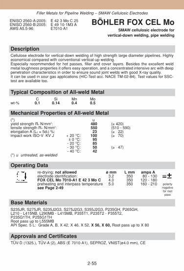
DescriptionCellulose electrode for vertical-down welding of high strength large diameter pipelines. Highlyeconomical compared with conventional vertical-up welding. Especially recommended for hot passes, filler and cover layers. Besides the excellent weldmetal toughness properties it offers easy operation, and a concentrated intensive arc with deeppenetration characteristics in order to ensure sound joint welds with good X-ray quality.It can be used in sour gas applications (HIC-Test acc. NACE TM-02-84). Test values for SSC-test are available too.
Approvals and CertificatesTÜV-D (1325.), TÜV-A (2), ABS (E 7010-A1), SEPROZ, VNIST(ø4.0 mm), CE
Base MaterialsS235JR, S275JR, S235J2G3, S275J2G3, S355J2G3, P235GH, P265GH,L210 - L415NB, L290MB - L415MB, P355T1, P235T2 - P355T2, P235G1TH, P255G1THRoot pass up to L555MBAPI Spec. 5 L: Grade A, B, X 42, X 46, X 52, X 56, X 60, Root pass up to X 80
Operating Datare-drying: not allowed ø mm L mm amps Aelectrode identification: 3.2 350 80 - 130FOX CEL Mo 7010-A1 E 42 3 Mo C 4.0 350 120 - 180preheating and interpass temperature 5.0 350 160 - 210see Page 2-49
Mechanical Properties of All-weld Metal(*) uyield strength Re N/mm2: 480 (≥ 420)tensile strength Rm N/mm2: 550 (510 - 590)elongation A (L0 = 5d0) %: 23 (≥ 322)impact work ISO-V KV J + 20 °C: 100 (≥ 370)
± 0 °C: 95- 20 °C: 85- 30 °C: 50 (≥ 347) - 40 °C: 42
(*) u untreated, as-welded
Typical Composition of All-weld MetalC Si Mn Mo
wt-% 0.1 0.14 0.4 0.5
ENISO 2560-A:2005: E 42 3 Mo C 25ENISO 2560-B:2005: E 49 10-1M3 AAWS A5.5-96: E7010-A1
BÖHLER FOX CEL MoSMAW cellulosic electrode for
vertical-down welding, pipe welding
2-55
polaritynegativefor rootpass
Filler Metals for Pipeline Welding – SMAW Cellulosic Electrodes

Description
Cellulose electrode for vertical-down welding of high strength large diameter pipelines. Highlyeconomical compared with conventional vertical-up welding. Especially recommended for hot passes, filler and cover layers. Without doubt BÖHLER FOXCEL 85 is the most popular cellulosic electrode which meets all the exacting demands of thefield welding of cross country pipelines extremely well. It ensures highest joint weld qualitydown to temperatures of -40 °C It can be used in sour gas applications (HIC-Test acc. NACE TM-02-84). Test values for SSC-test are available too.
Approvals and CertificatesTÜV-D (1361.), TÜV-A (3), ABS (E 8010-P1), FI (E 46 4 1Ni C 25), GdF (X), SEPROZ, GdFø 3.2;4.0;5.0 mm, PDO, CE
Base MaterialsL415NB - L485NB, L415MB - L485MBAPI Spec. 5 L: X 56, X 60, X 65, X 70
Operating Datare-drying: not allowed ø mm L mm amps Aelectrode identification: 3.2 350 80 - 130FOX CEL 85 8010-P1 E 46 4 1Ni C 4.0 350 120 - 180preheating and interpass temperature 5.0 350 160 - 210see Page 2-49
Mechanical Properties of All-weld Metal(*) uyield strength Re N/mm2: 490 (≥ 460)tensile strength Rm N/mm2: 570 (550 - 650)elongation A (L0 = 5d0) %: 23 (≥ 320)impact work ISO-V KV J + 20 °C: 110 (≥ 380)
± 0 °C: 105- 20 °C: 100- 40 °C: 70 (≥ 347)
(*) u untreated, as-welded
Typical Composition of All-weld MetalC Si Mn Ni
wt-% 0.14 0.15 0.75 0.7
ENISO 2560-A:2005: E 46 4 1Ni C 25ENISO 2560-B:2005: E 55 10-P1 A UAWS A5.5-96: E8010-P1
BÖHLER FOX CEL 85SMAW cellulosic electrode for
vertical-down welding, pipe welding
2-56
Filler Metals for Pipeline Welding – SMAW Cellulosic Electrodes

DescriptionCellulose electrode for vertical-down welding of high strength large diameter pipelines. Highlyeconomical compared with conventional vertical-up welding. Especially recommended for hot passes, filler and cover layers.The special design of the coating and the core wire guarantees the highest metallurgicalquality & soundness of the weld metal deposit with excellent mechanical properties. Theelectrode allows good weld pool visability, and easy manipulation in all positions, as well ashigh safety margins against porosity and slag inclusions.
Approvals and CertificatesTÜV-D (1324.), TÜV-A (4), GdF (X), Statoil, SEPROZ, GdF ø 3.2; 4.0; 5.0 mm; VNIIST, CE
Base MaterialsL450MB, L485MB, L555MBAPI Spec. 5 L: X 65, X 70, X 80
Operating Datare-drying: not allowed ø mm L mm amps Aelectrode identification: 4.0 350 120 - 180FOX CEL 90 9010-G E 50 3 1Ni C 5.0 350 160 - 210preheating and interpass temperaturesee Page 2-49
Mechanical Properties of All-weld Metal(*) uyield strength Re N/mm2: 610 (≥ 530)tensile strength Rm N/mm2: 650 (620 - 720)elongation A (L0 = 5d0) %: 21 (≥ 318)impact work ISO-V KV J + 20 °C: 100 (≥ 380)
± 0 °C: 90- 20 °C: 75- 30 °C: 65 (≥ 347)- 40 °C: 40 (≥ 327)
(*) u untreated, as-welded
Typical Composition of All-weld MetalC Si Mn Ni
wt-% 0.17 0.15 0.9 0.8
ENISO 2560-A:2005: E 50 3 1Ni C 25ENISO 2560-B:2005: E 57 10-G AAWS A5.5-96: E9010-G
BÖHLER FOX CEL 90SMAW cellulosic electrode for
vertical-down welding, pipe welding
2-57
Filler Metals for Pipeline Welding – SMAW Cellulosic Electrodes

DescriptionBasic electrode for vertical-down welding of root passes in pipeline construction and structural work.Also suitable for vertical-up welding of root passes. The deposit is extremely crack resistant and fea-tures high toughness and a very low hydrogen content. Highly economical compared with conventionalvertical-up welding.It can be used in sour gas applications (HIC-Test acc. NACE TM-02-84). Test values for SSC-test areavailable too.
Approvals and CertificatesTÜV-D (03532.), SEPROZ, CE
Base Materialsroot passes for following steels:S235J2G3 - S355J2G3, L290NB - L415NB, L290MB - L555MB,P235GH - P310GHAPI Spec. 5 L: X 42, X 46, X 52, X 56, X 60, X 70, X 80
Operating Datare-drying if necessary: ø mm L mm amps A300 - 350 °C, min. 2 h 2.5 350 80 - 110electrode identification: 3.2 350 100 - 160FOX BVD RP 8018-G E 46 3 BInterpass temperatures as required by the base material.
Mechanical Properties of All-weld Metal(*) uyield strength Re N/mm2: 510 (≥ 460)tensile strength Rm N/mm2: 560 (550 - 650)elongation A (L0 = 5d0) %: 26 (≥ 322)impact work ISO-V KV J + 20 °C: 170 (≥ 130)
± 0 °C: 150- 20 °C: 120- 30 °C: 60 (≥ 347)
(*) u untreated, as-welded
Typical Composition of All-weld MetalC Si Mn
wt-% 0.05 0.3 1.0
ENISO 2560-A:2005: E 46 3 B 41ENISO 2560-B:2005: E 55 18-G AAWS A5.5-96: E8018-G
BÖHLER FOX BVD RPSMAW basic electrode for
vertical-down welding, pipe welding
2-58
Filler Metals for Pipeline Welding – SMAW Basic Electrodes

DescriptionBasic electrodes for vertical-down welds of large diameter pipelines and for structural work.Suitable for filler and cover pass welding in pipeline construction. Deposit is extremely crack resi-stant, and features high toughness and a very low hydrogen content. Deposition rate is 80-100 % higher than for vertical up welding. The weld deposit of BÖHLER FOX BVD 85 shows anideal combination between high strength and cryogenic toughness down to -50 °C (-58 °F).Special design and development work has enabled this electrode to provide exceptional strikingcharacteristics and the avoidance of start porosity on cover (cap) passes. Due to this and thegood welding characteristics this special basic electrode offers easy handling even under fieldconditions.It can be used in sour gas applications (HIC-Test acc. NACE TM-02-84). Test values for SSC-test are available too.
Approvals and CertificatesTÜV-D (03531.), GdF, SEPROZ, CE
Base MaterialsS235J2G3 - S355J2G3, L290NB - L450NB, L290MB - L450MB,P235GH - P295GHAPI Spec. 5 L: A, B, X 42, X46, X 52, X 56, X 60, X 65
Operating Datare-drying if necessary: ø mm L mm amps A300 - 350 °C, min. 2 h 3.2 350 110 - 160electrode identification: 4.0 350 180 - 210FOX BVD 85 8018-G E 46 5 1Ni B 4.5 350 200 - 240Recommended interpass temperature > 80 °C
Mechanical Properties of All-weld Metal(*) uyield strength Re N/mm2: 510 (≥ 460)tensile strength Rm N/mm2: 560 (550 - 650)elongation A (L0 = 5d0) %: 27 (≥ 322)impact work ISO-V KV J + 20 °C: 170 (≥ 130)
± 0 °C: 150- 20 °C: 120- 40 °C: 85 (≥ 360) - 50 °C: 65 (≥ 347)
(*) u untreated, as-welded
Typical Composition of All-weld MetalC Si Mn Ni
wt-% 0.05 0.4 1.1 0.9
ENISO 2560-A:2005: E 46 5 1Ni B 45ENISO 2560-B:2005: E 55 48-G AAWS A5.5-96: E8018-G
BÖHLER FOX BVD 85SMAW basic electrode for
vertical-down welding, pipe welding
2-59
Filler Metals for Pipeline Welding – SMAW Basic Electrodes
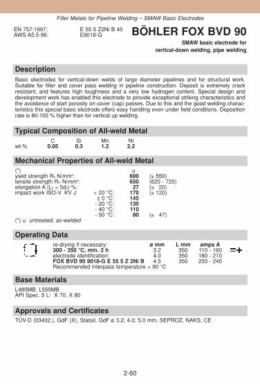
DescriptionBasic electrodes for vertical-down welds of large diameter pipelines and for structural work.Suitable for filler and cover pass welding in pipeline construction. Deposit is extremely crack resistant, and features high toughness and a very low hydrogen content. Special design anddevelopment work has enabled this electrode to provide exceptional striking characteristics andthe avoidance of start porosity on cover (cap) passes. Due to this and the good welding charac-teristics this special basic electrode offers easy handling even under field conditions. Depositionrate is 80-100 % higher than for vertical up welding.
Approvals and CertificatesTÜV-D (03402.), GdF (X), Statoil, GdF ø 3.2; 4.0; 5.0 mm, SEPROZ, NAKS, CE
Base MaterialsL485MB, L555MBAPI Spec. 5 L: X 70, X 80
Operating Datare-drying if necessary: ø mm L mm amps A300 - 350 °C, min. 2 h 3.2 350 110 - 160electrode identification: 4.0 350 180 - 210FOX BVD 90 9018-G E 55 5 Z 2Ni B 4.5 350 200 - 240Recommended interpass temperature > 90 °C
Mechanical Properties of All-weld Metal(*) uyield strength Re N/mm2: 600 (≥ 550)tensile strength Rm N/mm2: 650 (620 - 720)elongation A (L0 = 5d0) %: 27 (≥ 320)impact work ISO-V KV J + 20 °C: 170 (≥ 120)
± 0 °C: 145- 20 °C: 130- 40 °C: 110- 50 °C: 80 (≥ 347)
(*) u untreated, as-welded
Typical Composition of All-weld MetalC Si Mn Ni
wt-% 0.05 0.3 1.2 2.2
EN 757:1997: E 55 5 Z2Ni B 45AWS A5.5-96: E9018-G BÖHLER FOX BVD 90
SMAW basic electrode for vertical-down welding, pipe welding
2-60
Filler Metals for Pipeline Welding – SMAW Basic Electrodes

DescriptionBasic electrodes for vertical-down welds of large diameter pipelines and for structural work.Suitable for filler and cover pass welding in pipeline construction. Deposit is extremely crackresistant, and features high toughness and a very low hydrogen content. Special design anddevelopment work has enabled this electrode to provide exceptional striking characteristics andthe avoidance of start porosity on cover (cap) passes. Due to this and the good welding characteristics this special basic electrode offers easy handling even under field conditions.Deposition rate is 80-100 % higher than for vertical up welding.
Approvals and CertificatesTÜV-D (06333.), SEPROZ, CE
Base MaterialsL555MBAPI Spec. 5 L: X 80
Operating Datare-drying if necessary: ø mm L mm amps A300 - 350 °C, min. 2 h 4.0 350 180 - 210electrode identification: 4.5 350 200 - 240FOX BVD 100 10018-G E 62 5 Z2Ni BRecommended interpass temperature > 100 °C
Mechanical Properties of All-weld Metal(*) uyield strength Re N/mm2: 670 (≥ 620)tensile strength Rm N/mm2: 730 (690 - 810)elongation A (L0 = 5d0) %: 24 (≥ 318)impact work ISO-V KV J + 20 °C: 150 (≥ 110)
± 0 °C: 125- 20 °C: 120- 50 °C: 70 (≥ 347)
(*) u untreated, as-welded
Typical Composition of All-weld MetalC Si Mn Ni
wt-% 0.07 0.4 1.2 2.3
EN 757:1997: E 62 5 Z2Ni B 45AWS A5.5-96: E10018-G BÖHLER FOX BVD 100
SMAW basic electrode for vertical-down welding, pipe welding
2-61
Filler Metals for Pipeline Welding – SMAW Basic Electrodes

DescriptionBasic electrodes for vertical-down welds of large diameter pipelines and for structural work.Suitable for filler and cover pass welding in pipeline construction. Deposit is extremely crack resi-stant, and features high toughness and a very low hydrogen content. Deposition rate is 80-100 % higher than for vertical up welding. This electrode has become optimised for best strikingproperties and for avoiding start porosity in the cap layer. With its excellent welding properties the electrode offers easy handling also under difficult conditions.
Approvals and CertificatesSEPROZ
Base MaterialsL690*API Spec. 5 L: X100** not standardised yet
Operating Datare-drying if necessary: ø mm L mm amps A300 - 350 °C, min. 2 h 4.0 350 180-210electrode identification: 4.5 350 200-240FOX BVD 110 11018-G E 69 3 Mn2NiMo BRecommended interpass temperature > 110 °C
Mechanical Properties of All-weld Metal(*) uyield strength Re N/mm2: 720 (≥ 690)tensile strength Rm N/mm2: 810 (≥ 760)elongation A (L0 = 5d0) %: 20 (≥ 317)impact work ISO-V KV J + 20 °C: 90 (≥ 380)
- 20 °C: 70 (≥ 350)- 40 °C: 50 (≥ 340)
(*) u untreated, as-welded
Typical Composition of All-weld MetalC Si Mn Ni Mo
wt-% 0.07 0.4 1.5 2.2 0.4
EN 757:1997: E 69 3 Mn2NiMo B 45AWS A5.5-96: E11018-G BÖHLER FOX BVD 110
SMAW basic electrode for vertical-down welding, pipe welding
2-62
Filler Metals for Pipeline Welding – SMAW Basic Electrodes

2-63
DescriptionBasic electrodes for vertical-down welds of large diameter pipelines and for structural work.Suitable for filler and cover pass welding in pipeline construction. Deposit is extremely crackresistant, and features high toughness and a very low hydrogen content. Deposition rate is 80-100 % higher than for vertical up welding. This electrode is optimised for best striking properties and for avoiding start porosity in the caplayer. With its excellent welding properties the electrode offers easy handling also under diffi-cult conditions.
Base MaterialsEN: L6901)
API Spec. 5 L: X1001), X1101) 1) not standardised yet
Operating Datare-drying if necessary ø mm L mm amps A300-350 °C, min. 2 h 3.2 350 110-160electrode identification: 4.0 350 180-220FOX BVD 120 12018-G E 69 3 Mn2NiMo BRecommended interpass temperature >120 °C
Mechanical Properties of All-weld Metal(*) uyield strength Re N/mm2: 815 (≥ 740)tensile strength Rm N/mm2: 870 (≥ 830)elongation A (L0=5d0) %: 18 (≥ 17)impact work ISO-V KV J +20 °C: 80 (≥ 80)
-20 °C: 60 (≥ 50)-40 °C: 50 (≥ 40)
(*) u untreated, as-welded
Typical Composition of All-weld MetalC Si Mn Ni Mo
wt-% 0.07 0.4 1.85 2.25 0.35
EN 757: 1997: E 69 3 Mn2NiMo B 45AWS A5.5-96: E12018-G BÖHLER
FOX BVD 120 SMAW basic electrode for
vertical-down welding, pipe welding
Filler Metals for Pipeline Welding – SMAW Basic Electrodes
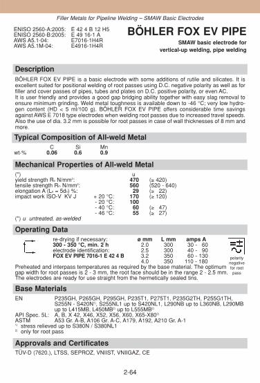
DescriptionBÖHLER FOX EV PIPE is a basic electrode with some additions of rutile and silicates. It isexcellent suited for positional welding of root passes using D.C. negative polarity as well as forfiller and cover passes of pipes, tubes and plates on D.C. positive polarity, or even AC. It is user friendly and provides a good gap bridging ability together with easy slag removal toensure minimum grinding. Weld metal toughness is available down to -46 °C; very low hydro-gen content (HD < 5 ml/100 g). BÖHLER FOX EV PIPE offers considerable time savingsagainst AWS E 7018 type electrodes when welding root passes due to increased travel speeds.Also the use of dia. 3.2 mm is possible for root passes in case of wall thicknesses of 8 mm andmore.
Approvals and CertificatesTÜV-D (7620.), LTSS, SEPROZ, VNIIST, VNIIGAZ, CE
Base MaterialsEN P235GH, P265GH, P295GH, P235T1, P275T1, P235G2TH, P255G1TH,
S255N - S420N1), S255NL1 up to S420NL1, L290NB up to L360NB, L290MBup to L415MB, L450MB2) up to L555MB2)
API Spec. 5L: A, B, X 42, X46, X52, X56, X60, X65-X802)
ASTM A53 Gr. A-B, A106 Gr. A-C, A179, A192, A210 Gr. A-11) stress relieved up to S380N / S380NL12) only for root pass
Operating Datare-drying if necessary: ø mm L mm amps A300 - 350 °C, min. 2 h 2.0 300 130 - 160 electrode identification: 2.5 300 140 - 190 FOX EV PIPE 7016-1 E 42 4 B 3.2 350 160 - 130
4.0 350 110 - 180Preheated and interpass temperatures as required by the base material. The optimum gap width for root passes is 2 - 3 mm, the root face should be in the range 2 - 2.5 mm. The electrodes are ready for use straight from the hermetically sealed tins.
Mechanical Properties of All-weld Metal(*) uyield strength Re N/mm2: 470 (≥ 420)tensile strength Rm N/mm2: 560 (520 - 640)elongation A (L0 = 5d0) %: 29 (≥ 322)impact work ISO-V KV J + 20 °C: 170 (≥ 120)
- 20 °C: 100- 40 °C: 60 (≥ 347)- 46 °C: 55 (≥ 327)
(*) u untreated, as-welded
Typical Composition of All-weld MetalC Si Mn
wt-% 0.06 0.6 0.9
ENISO 2560-A:2005: E 42 4 B 12 H5ENISO 2560-B:2005: E 49 16-1 AAWS A5.1-04: E7016-1H4RAWS A5.1M-04: E4916-1H4R
BÖHLER FOX EV PIPESMAW basic electrode for
vertical-up welding, pipe welding
2-64
Filler Metals for Pipeline Welding – SMAW Basic Electrodes
polaritynegativefor rootpass

2-65
DescriptionBasic electrode excellent suited for positional welding of root passes using D.C. negative pola-rity as well as for filler and cover passes for pipes, tubes and plates on D.C. positive polarity,or even A.C. The electrode offers considerable time savings against AWS E 8018 type electro-des when welding root passes due to increased travel speeds. Good impact properties downto -40 °C, low hydrogen content (HD < 5 ml/100 g), as well as packaging in hermetically sealed tins are further features for the user. BÖHLER FOX EV 60 PIPE offers considerable timesavings against AWS E 8018 type electrodes when welding root passes due to increased travel speeds. Also the use of dia. 3.2 mm is possible for root passes in case of wall thick-nesses of 8 mm and more.
Approvals and CertificatesVNIIGAZ
Base MaterialsEN: S235J2G3 - S355J2G3, L210NB - L450NB, L210MB - L450MB, P235GH -
P295GH, E295, E335, S355J2G3, C35-C45, P310GH, S380N - S460N, P380NH-P460NH, S380NL - S460NL, S380NL1 - S460NL2, GE260-GE300
API Spec. 5 L: X42, X46, X52, X56, X60, X65ASTM A516 Gr. 65, A572 Gr. 55, 60, 65, A633 Gr. E, A612, A618 Gr. I, A537 Gr. 1-3
Operating Datare-drying if necessary: ø mm L mm amps A300 - 350 °C, min. 2 h 2.5 300 140 - 190 electrode identification: 3.2 350 160 - 130 FOX EV 60 PIPE 8016-G E 50 4 1 Ni B 4.0 350 110 - 180
5.0 450 180 - 230Preheated and interpass temperatures as required by the base material.The optimum gap width for root passes is 2-3 mm, the root face should be in the range 2-2.5 mm. The electrodes are ready for use straight from the hermetically sealed tins.
Mechanical Properties of All-weld Metal(*) uyield strength Re N/mm2: 550 (≥ 500)tensile strength Rm N/mm2: 590 (560 - 720)elongation A (L0 = 5d0) %: 29 (≥ 322)impact work ISO-V KV J + 20 °C: 170 (≥ 130)
0 °C: 150-20 °C: 140-40 °C: 110 (≥ 47)-46 °C: 60
(*) u untreated, as-welded
Typical Composition of All-weld MetalC Si Mn Ni
wt-% 0.07 0.6 1.2 0.9
ENISO 2560-A:2005: E 50 4 1Ni B 12 H5ENISO 2560-B:2005: E 55 16-G A H5AWS A5.5-96: E8016-G H4R
BÖHLER FOX EV 60 PIPE
SMAW basic electrode forvertical-up welding, pipe welding
Filler Metals for Pipeline Welding – SMAW Basic Electrodes
polaritynegativefor rootpass
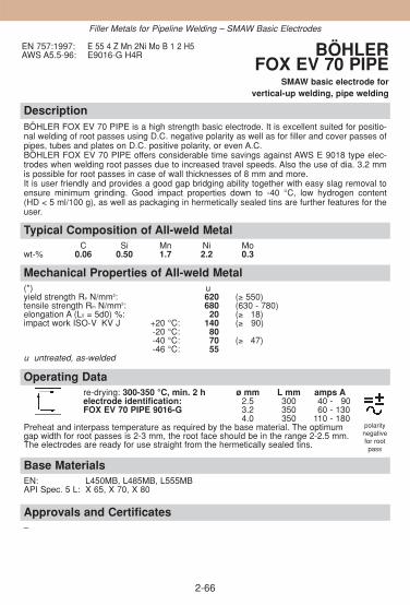
DescriptionBÖHLER FOX EV 70 PIPE is a high strength basic electrode. It is excellent suited for positio-nal welding of root passes using D.C. negative polarity as well as for filler and cover passes ofpipes, tubes and plates on D.C. positive polarity, or even A.C.BÖHLER FOX EV 70 PIPE offers considerable time savings against AWS E 9018 type elec-trodes when welding root passes due to increased travel speeds. Also the use of dia. 3.2 mmis possible for root passes in case of wall thicknesses of 8 mm and more. It is user friendly and provides a good gap bridging ability together with easy slag removal toensure minimum grinding. Good impact properties down to -40 °C, low hydrogen content(HD < 5 ml/100 g), as well as packaging in hermetically sealed tins are further features for theuser.
Approvals and Certificates–
Base MaterialsEN: L450MB, L485MB, L555MBAPI Spec. 5 L: X 65, X 70, X 80
Operating Datare-drying: 300-350 °C, min. 2 h ø mm L mm amps Aelectrode identification: 2.5 300 40 - 90FOX EV 70 PIPE 9016-G 3.2 350 60 - 130
4.0 350 110 - 180Preheat and interpass temperature as required by the base material. The optimum gap width for root passes is 2-3 mm, the root face should be in the range 2-2.5 mm. The electrodes are ready for use straight from the hermetically sealed tins.
Mechanical Properties of All-weld Metal(*) uyield strength Re N/mm2: 620 (≥ 550)tensile strength Rm N/mm2: 680 (630 - 780)elongation A (L0 = 5d0) %: 20 (≥ 318)impact work ISO-V KV J +20 °C: 140 (≥ 90)
-20 °C: 80-40 °C: 70 (≥ 347)-46 °C: 55
u untreated, as-welded
Typical Composition of All-weld MetalC Si Mn Ni Mo
wt-% 0.06 0.50 1.7 2.2 0.3
EN 757:1997: E 55 4 Z Mn 2Ni Mo B 1 2 H5AWS A5.5-96: E9016-G H4R BÖHLER
FOX EV 70 PIPESMAW basic electrode for
vertical-up welding, pipe welding
2-66
Filler Metals for Pipeline Welding – SMAW Basic Electrodes
polaritynegativefor rootpass

2-67
DescriptionBÖHLER SG 3-P is a micro alloyed GMAW solid wire designed for high quality automaticwelding of pipelines. An optimum balanced alloying concept ensures good weld metalproperties to fulfil the high requirements in the On-Offshore-Pipeline Industry. Deposit isextremely crack resistant and the weld metal toughness is available down to -50 °C. The very important quality aspects, prerequisite for uninterrupted feedability of the solid wiree.g. helix of the wire, copper coating, close wire diameter tolerance and precision layer woundspooling are taken into account during the production.
Approvals and CertificatesTÜV-D (07682.), CE
Base MaterialsEN: L290MB - L485MB API Spez. 5L: X42, X46, X52, X56, X60, X65
Operating Datashielding gases: ø mmArgon + 15 - 25 % CO2 0.9100 % CO2
Preheating and interpass temperature as required by the base metal.
Mechanical Properties of All-weld Metal(*) u u1yield strength Re N/mm2: 510 (≥ 470) 470 (≥ 440)tensile strength Rm N/mm2: 640 (600 - 680) 610 (570 - 640)elongation A (L0 = 5d0) %: 25 (≥ 324) 26 (≥ 325)impact work ISO-V KV J + 20 °C: 120 (≥ 100) 100 (≥ 395)
- 40 °C: 75 (≥ 365) 60 (≥ 347)- 50 °C: 55 (≥ 347)
(*) u untreated, as-welded - shielding gas Ar + 15 - 25 % CO2
u1 untreated, as-welded - shielding gas 100 % CO2
Typical Composition of Solid WireC Si Mn Ti
wt-% 0.05 0.75 1.55 +
EN 440:1995: G4Si1 (for wire)EN 440:1995: G 46 5 M G0 G4Si1
G 42 4 C G0 G4Si1AWS A5.18-01: ER70S-GAWS A5.18M-01: ER485S-G
BÖHLER SG 3-PGMAW solid wire for
automatic pipe welding
Filler Metals for Pipeline Welding – GMAW Solid Wires
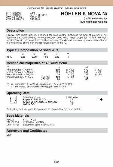
2-68
DescriptionGMAW wire micro alloyed, designed for high quality automatic welding of pipelines. An optimum balanced alloying concept ensures good weld metal properties to fulfil the high requirements in the on-offshore pipeline industry. The deposit is extremely crack resistant andthe weld metal offers high impact values down to -50 °C.
Approvals and CertificatesDNV
Base MaterialsAPI5L: X 42 – X 70 EN 10208-2: L290MB – L485MBDIN 17172: StE290TM up to StE480.7TM
Operating DataShielding gases ø mm wireArgon +15-25 % CO2 0.9Argon +0-5 % CO2 +3-10 % O2 1.0100 % CO2 1.2
Preheating and interpass temperature as required by the base metal.
Mechanical Properties of All-weld Metal(*) u u1yield strength Re N/mm2: 500 (> 420) 470 (> 420)tensile strength Rm N/mm2: 590 (> 550) 560 (> 500)elongation A (L0 = 5d0) %: 24 (> 20) 25 (> 20)impact work ISO-V KV J + 20 °C: 150 (≥ 47) 110
- 50 °C: 80 45
(*) u untreated, as-welded shielding gas: Ar +15-25 % CO2
u1 untreated, as-welded shielding gas: 100 % CO2
Typical Composition of Solid WireC Si Mn Ni Ti
wt-% 0.06 0.70 1.50 0.90 +
EN 440:1995: G3Ni1EN 440:1995: G 42 5 M G3Ni1AWS A5.28-05: ER80S-GAWS A5.28M-05: ER55S-G
BÖHLER K NOVA NiGMAW solid wire for
automatic pipe welding
Filler Metals for Pipeline Welding – GMAW Solid Wires

2-69
DescriptionCopper coated GMAW wire for high strength, quenched and tempered fine-grained construc-tional steels. The wire is suited for joint welding in boiler, pressure vessel, pipeline, and craneconstruction as well as in structural steel engineering. The typical composition of the wirefulfils the requirements of the NORSOK-regulation for „water injection systems“.Due to the precise addition of micro alloying elements NiMo1-IG wire features excellent ductilityand crack resistance in spite of its high strength. Good cryogenic impact energy down to -60 °C,low hydrogen contents in the deposit, best feedability and low copper contents are otheradvantages of this wire.
Approvals and CertificatesDB (42.014.06), ÖBB, GL (4Y55S), SEPROZ, CE
Base Materialspipe steels and fine-grained steelsS460N - S500N, S460NL - S500NL, S500NC - S550NC, L480MB, L555MBquenched and tempered fine-grained steelse. g. N-A-XTRA 56-70, BHV 70, PAS 700, HSM 700, 20MnMoNi5-5API Spec. 5L: X 70, X 80
Operating Datashielding gases: ø mmArgon + 15 - 25 % CO2 0.9Argon + 0.5 % CO2 + 3–10 % O2 1.0100 % CO2
Preheating and interpass temperature as required by the base metal.
Mechanical Properties of All-weld Metal(*) u u1yield strength Re N/mm2: 620 (≥ 550) 590 (≥ 550)tensile strength Rm N/mm2: 700 (650 - 800) 680 (620 - 770)elongation A (L0 = 5d0) %: 23 (≥ 320) 22 (≥ 320)impact work ISO-V KV J + 20 °C: 140 (≥ 120) 120 (≥ 100)
- 40 °C: 110 (≥ 390) (≥ 347)- 60 °C: (≥ 347)
(*) u untreated, as-welded - shielding gas Ar + 15 - 25 % CO2
u1 untreated, as-welded - shielding gas 100 % CO2
Typical Composition of Solid WireC Si Mn Mo Ni
wt-% 0.08 0.6 1.8 0.3 0.9
EN 12534:1999: Mn3Ni1Mo (for wire)EN 12534:1999: G 55 6 M Mn3Ni1Mo
G 55 4 C Mn3Ni1MoAWS A5.28-05: ER90S-GAWS A5.28M-05: ER62S-G
BÖHLER NiMo 1-IGGMAW solid wire for
automatic pipe welding
Filler Metals for Pipeline Welding – GMAW Solid Wires

2-70
Notes

2-71
2.4. Filler Metals for Weather-resistant,High-strength and Cryogenic Steels
ObjectivesThis section provides detailed product information for filler metals that maybe used to weld weather-resistant, high-tensile and cryogenic steels. Weather-resistant steels are used in all areas of structural steel engineeringand light-gauge steel construction, amongst other things for overhead wireand overhead trolley wire masts, in the form of rod and sectional steel, light-gauge sheets and heavy plates. Due to their excellent strength propertiesthey may also be used for higher operating temperatures (over 400 °C)although in this case the proof stress decreases considerably. High-tensile steels may be used down to very low temperatures in structuralsteel engineering and plant construction, the construction of vehicles,wagons and agricultural machinery for welded structures subject to highstatic and dynamic loads. The cryogenic qualities and special qualities ofsteel may be used down to -60 °C without fear of brittle fracture. Generallyspeaking it should be noted that increased care must be taken during fabri-cation and a structural design suitable for welding and withstanding stress isan essential prerequisite since the minimum values of the yield stress rise asthe wall thickness increases. Cryogenic steels are intended for components subject to static and dynamicloads at operating temperatures below -40 °C in gas liquefaction plants in theprocessing of mineral oil, for fractionated distillation of hydrocarbons, for thetransport of liquefied natural gas and in air liquefaction plants. Consult thebuilding regulations for pressurised vessels with regard to special applicati-ons.
Contents
OVERVIEW ................................................................................................72
SMAW COVERED ELECTRODES ............................................................74
GTAW RODS..............................................................................................85
GMAW SOLID WIRES ...............................................................................88
FLUX CORED WIRE..................................................................................95
SAW WIRE/FLUX-COMBINATIONS ..........................................................96
◆
◆
Product Information

2-72
Overview – Classifications
Böhler EN / ENISO AWSSMAW covered electrodesFOX NiCuCr ENISO 2560-A: E 46 4 Z (NiCrCu) B 42 H5 A5.5-96: E8018-W2H4RFOX EV 60 ENISO 2560-A: E 46 6 1Ni B 42 H5 A5.5-96: E8018-C3H4RFOX EV 63 ENISO 2560-A: E 50 4 B 42 H5 A5.5-96: E8018-GH4RFOX EV 65 EN 757: E 55 6 1NiMo B 42 H5 A5.5-96: E8018-GH4R
E8018-D1H4R (mod.)FOX EV 70 EN 757: E 55 6 1NiMo B 42 H5 A5.5-96: E9018-GH4R
E9018-D1H4R (mod.)FOX EV 70 Mo EN 757: E 55 3 MnMo B T 42 H10 A5.5-96: E9018-G
E9018-D1(mod.)FOX NiMo 100 EN 757: E 62 4 Mn1NiMoB 42 H5 A5.5-96: E10018-G
(E10018-D2mod.)FOX EV 75 EN 757: E 62 6 Mn2NiCrMo B42 H5 A5.5-96: E10018-GH4R
E10018-MH4R(mod.)FOX EV 85 EN 757: E 69 6 Mn2NiCrMo B42 H5 A5.5-96: E11018-GH4R
E11018-MH4R(mod.)FOX EV 85 M – A5.5-96: E11018-MH4RFOX EV 100 EN 757: E 89 4 Mn2Ni1CrMoB42 H5 A5.5-96: E12018GFOX 2.5 Ni ENISO 2560-A: E 46 8 2Ni B 42 H5 A5.5-96: E8018-C1H4R
GTAW rodsDMO-IG EN 1668: W 46 3 W2Mo A5.28-05: ER80S-G
ER70S-A1I 52 Ni EN 1668: W 3 Ni 1 A5.28-05: ER80S-Ni1(mod.)2.5 Ni-IG EN 1668: W 46 8 W2Ni2 A5.28-05: ER80S-Ni2
GMAW solid wiresNiCu 1-IG EN 440: G 42 4 M G0 A5.28-05: ER80S-G
G 42 4 C G0K Nova Ni EN 440: G 3 Ni 1 A5.28-05: ER80S-GNiMo 1-IG EN 12534: G 55 6 M Mn3Ni1Mo A5.28-05: ER90S-G
G 55 4 C Mn3Ni1MoNiCrMo 2.5-IG EN 12534: G 69 6 M Mn3Ni2.5CrMo A5.28-05: ER110S-G
G 69 4 C Mn3Ni2.5CrMoX 70-IG EN 12534: G 69 5 M Mn3Ni1CrMo A5.28-05: ER110S-GX 90-IG EN 12534: G 89 6 M Mn4Ni2CrMo A5.28-05: ER120S-G2.5 Ni-IG EN 440: G 46 8 M G2 Ni2 A5.28-05: ER80S-Ni2
G 46 6 C G2 Ni2
Flux cored wireTi 60-FD EN 758: T 50 6 1 Ni P M 1 H5 A5.20-95: E81T1-Ni1MH8
SAW wire/flux-combinations3 NiMo 1-UP EN 756: S 3Ni1Mo A5.23-97: EF3(mod.)3 NiMo 1-UP/BB24 EN 756: S 50 4 FB S3Ni1Mo A5.23-97: F9A4-EF3(mod.)-F3
F62A4-EF3(mod.)-F33 NiCrMo 2.5-UP EN 756: S Z 3Ni2CrMo A5.23-97: EM4(mod.)3 NiCrMo 2.5-UP/BB 24 S 69 6 FB S Z 3Ni2CrMo A5.23-97: F11A8-EM4(mod.)-M4
F76A6-EM4(mod.)-M4Ni 2-UP EN 756: S 2Ni2 A5.23-97: ENi2Ni 2-UP/BB 24 EN 756: S 46 6 FB S2Ni2 A5.23-97: F8A8-ENi2-Ni2
F55A6-ENi2-Ni2
◆
High Strength/Cryogenic Filler Metals

2-73
Overview – Typical Chemical Composition
Böhler C Si Mn Cr Ni Mo V CuSMAW covered electrodesFOX NiCuCr 0.05 0.4 0.7 0.6 0.6 0.45FOX EV 60 0.07 0.4 1.15 0.9FOX EV 63 0.08 0.7 1.7FOX EV 65 0.06 0.3 1.2 0.8 0.35
FOX EV 70 0.04 0.3 1.2 0.9 0.4
FOX EV 70 Mo 0.06 0.4 1.6 0.5
FOX NiMo 100 0.11 0.25 1.85 0.95 0.4
FOX EV 75 0.05 0.4 1.6 0.4 2.0 0.4
FOX EV 85 0.05 0.4 1.7 0.4 2.0 0.5
FOX EV 85 M 0.05 0.2 1.5 0.35 2.2 0.35FOX EV 100 0.06 0.35 1.8 0.7 2.5 0.5 0.07FOX 2.5 Ni 0.04 0.3 0.8 2.4
GTAW rodsDMO-IG 0.1 0.6 1.2 0.5I 52 Ni 0.07 0.7 1.4 0.92.5 Ni-IG 0.08 0.6 1.0 2.5
GMAW solid wiresNiCu 1-IG 0.1 0.5 1.1 0.9 0.4
K Nova Ni 0.06 0.7 1.5 0.9 Ti +NiMo 1-IG 0.08 0.6 1.8 0.9 0.3
NiCrMo 2.5-IG 0.08 0.6 1.4 0.30 2.5 0.4
X 70-IG 0.1 0.6 1.6 0.25 1.3 0.25 0.1X 90-IG 0.1 0.8 1.8 0.35 2.25 0.62.5 Ni-IG 0.08 0.6 1.0 2.5
Flux cored wireTi 60-FD 0.06 0.45 1.2 0.85
SAW wire/flux-combinations3 NiMo 1-UP 0.13 0.15 1.7 0.95 0.553 NiMo 1-UP/BB24 0.09 0.25 1.65 0.90 0.50
3 NiCrMo 2.5-UP 0.12 0.15 1.5 0.6 2.3 0.553 NiCrMo 2.5-UP/BB 24 0.06 0.3 1.5 0.50 2.2 0.50
Ni 2-UP 0.10 0.12 1.05 2.3Ni 2-UP/BB 24 0.07 0.25 1.1 2.2
◆
High Strength/Cryogenic Filler Metals

DescriptionNiCuCr alloyed basic electrode for welding weathering resistant constructional steels such asCORTEN, PANTINAX, CORALDUR and KORRALPIN. Excellent mechanical properties, andhigh crack resistance even when subjected to restraint. Metal recovery approx. 115 %. Easily weldable in all positions except vertical-down. Very lowhydrogen contents (according AWS condition HD ≤ 4 ml/100 g weld metal).
Approvals and CertificatesRMR (3 YHH)
Similar-alloy Filler MetalsGMAW solid wire: NiCu 1-IG
Base Materialsweather-resistant constructional steels
S235JR, S235JRW, S355JRW, S355J2G3 Cu
ASTM A36, A283 Gr. B, C
Operating Datare-drying if necessary: ø mm L mm amps A300 - 350 °C, min. 2 h 2.5 350 80 - 110electrode identifikation: 3.2 350 130 - 150FOX NiCuCr 8018-W2 E 46 4 Z B 4.0 450 150 - 190
Mechanical Properties of All-weld Metal(*) u syield strength Re N/mm2: 520 (≥ 460) 500 (≥ 410)tensile strength Rm N/mm2: 570 (530 - 680) 550 (490 - 610)elongation A (L0 = 5d0) %: 27 (≥ 325) 27 (≥ 326)impact work ISO-V KV J + 20 °C: 200 (≥ 140) 190 (≥ 118)
- 30 °C: 150 (≥ 110)- 40 °C: 130 (≥ 190)
(*) u untreated, as-weldeds stress relieved 580 °C/2 h/furnace down to 300 °C/air
Typical Composition of All-weld MetalC Si Mn Cr Ni Cu
wt-% 0.05 0.4 0.7 0.6 0.6 0.45
ENISO 2560-A:2005: E 46 4 ZNiCrCu B 42 H5ENISO 2560-B:2005: E 49 18-G A H5AWS A5.5-96: E8018-W2H4R
BÖHLER FOX NiCuCrSMAW basic electrode, low-alloyed,
weather resistant
2-74
High Strength/Cryogenic Filler Metals – SMAW Covered Electrodes

DescriptionBasic Ni-alloyed electrode with excellent mechanical properties, particularly high toughnessand crack resistance. For higher strength fine-grained constructional steels. Suitable for service temperatures at -60 °C to + 350 °C. Very good impact strength in aged condition. Metal recovery about 115 %. Easily weldable in all positions except vertical-down. Very low hydrogen content (according AWS condition HD ≤ 4 ml/100 g weld metal).
Approvals and CertificatesTÜV-D (1524.), TÜV-A (275), DNV (3 YHH), RMR (3 YHH), Statoil, LTSS, SEPROZ, CRS (3YH5), CE
Base Materialsconstructional steels, pipe- and vessel steels, cryogenic fine-grained steels and special grades
E295, E335, S355J2G3, C35-C45, L210 - L450NB, L245MB - L450MB, P310GH, P355 NL1 -P460NL1, P355NL2 - P460NL2, S380N - S460N, P355NH-P460NH, S380NL - S460NL,S380NL1, GE260-GE300
ASTM A516 Gr. 65, A572 Gr. 55, 60, 65, A633 Gr. E, A612, A618 Gr. I, A537 Gr. 1-3.
Operating Datare-drying if necessary: ø mm L mm amps A300 - 350 °C, min. 2 h 2.5 350 80 - 100electrode identifikation: 3.2 350 110 - 140FOX EV 60 8018-C3 E 46 6 1Ni B 4.0 450 140 - 180
5.0 450 190 - 230
Mechanical Properties of All-weld Metal(*) u syield strength Re N/mm2: 510 (≥ 470) 480 (≥ 460)tensile strength Rm N/mm2: 610 (580 - 680) 580 (560 - 680)elongation A (L0 = 5d0) %: 27 (≥ 324) 27 (≥ 323)impact work ISO-V KV J + 20 °C: 180 (≥ 130) 160 (≥ 120)
- 60 °C: 110 (≥ 365)(*) u untreated, as-welded
s stress relieved 580 °C/2 h/furnace down to 300 °C/air
Typical Composition of All-weld MetalC Si Mn Ni
wt-% 0.07 0.4 1.15 0.9
ENISO 2560-A:2005: E 46 6 1Ni B 42 H5ENISO 2560-B:2005: E 55 18-N2 A U H5AWS A5.5-96: E8018-C3H4R
BÖHLER FOX EV 60SMAW basic electrode, low-alloyed,
high strength
2-75
High Strength/Cryogenic Filler Metals – SMAW Covered Electrodes

DescriptionBasic electrode for carbon and low-alloy steels of higher strength with carbon contents up to0.6 %. Also suitable for rail joint welding. Ductile and crack resistant weld metal. Metal recovery approx. 115 %. Weldable in all positionsexcept vertical-down. Very low hydrogen content (according AWS condition HD ≤ 4 ml/100 g weld metal).
Approvals and CertificatesTÜV-D (0730.), DB (10.014.07 / 81.014.01), ÖBB, TÜV-A (X), RMR (3 YHH), SEPROZ, CE
Base Materialsconstructional steels, pipe steels, rail steels
S355J2G3, E295 - E360, C35 - C60, S355N - S500N, P315NH - P500NH, GE200 - GE300,R0800
ASTM A225 Gr. C; A517 Gr. A, B, C, E, F, H, J, K, M, P
Operating Datare-drying if necessary: ø mm L mm amps A300 - 350 °C, min. 2 h 2.5 350 80 - 110electrode identifikation: 3.2 350 100 - 140FOX EV 63 8018-G E 50 4 B 4.0 450 140 - 180
5.0 450 190 - 230
Mechanical Properties of All-weld Metal(*) u syield strength Re N/mm2: 580 (≥ 500) 560 (≥ 500)tensile strength Rm N/mm2: 630 (610 - 720) 610 (590 - 710)elongation A (L0 = 5d0) %: 26 (≥ 322) 26 (≥ 324)impact work ISO-V KV J + 20 °C: 170 (≥ 140) 130 (≥ 100)
- 40 °C: 90 (≥ 147)(*) u untreated, as-welded
s stress relieved 580 °C/2 h/furnace down to 300 °C/air
Typical Composition of All-weld MetalC Si Mn
wt-% 0.08 0.7 1.7
ENISO 2560-A:2005: E 50 4 B 42 H5ENISO 2560-B:2005: E 57 18-G A H5AWS A5.5-96: E8018-GH4R
BÖHLER FOX EV 63SMAW basic electrode, low-alloyed,
high strength
2-76
High Strength/Cryogenic Filler Metals – SMAW Covered Electrodes

DescriptionBasic electrode with high ductility and crack resistance, for high-strength fine-grained steels.Ductile down to -60 °C. Resistant to ageing. Easy to handle in all positions except vertical-down. Very low hydrogen content (according AWS condition HD ≤ 4 ml/100 g weld metal).
Approvals and CertificatesTÜV-D (1802.), SEPROZ, CE
Base Materialsconstructional steels, pipe- and vessel steels, cryogenic fine-grained steels and special grades
E295 - E360, 20MnMoNi5-5, 22NiMoCr4-7, P355NL1 - P460NL1, P355NL2 - P460NL2,S380N - S500N, S355NH - S460NH, S380NL - S500NL, S380NL1 - S500NL1,15NiCuMoNb5S (WB 36), 20MnMoNi5-5, 17MnMoV6-4 (WB 35), 22NiMoCr4-7
ASTM A302 Gr. A-D; A517 Gr. A, B, C, E, F, H, J, K, M, P; A225 Gr. C; A572 Gr. 65
Operating Datare-drying if necessary: ø mm L mm amps A300 - 350 °C, min. 2 h 2.5 350 80 - 100electrode identifikation: 3.2 350 100 - 140FOX EV 65 8018-G E 55 6 1NiMo B 4.0 450 140 - 180
Preheating and interpass temperature, as well as post weld heat treatment as required by thebase metal.
Mechanical Properties of All-weld Metal(*) u syield strength Re N/mm2: 600 (≥ 550) 580 (≥ 530)tensile strength Rm N/mm2: 650 (630 - 750) 630 (620 - 730)elongation A (L0 = 5d0) %: 25 (≥ 320) 25 (≥ 320)impact work ISO-V KV J + 20 °C: 180 (≥ 130) 160 (≥ 120)
- 60 °C: 80 (≥ 347)(*) u untreated, as-welded
s stress relieved 580 °C/2 h/furnace down to 300 °C/air
Typical Composition of All-weld MetalC Si Mn Ni Mo
wt-% 0.06 0.3 1.2 0.8 0.35
EN 757:1997: E 55 6 1NiMo B 4 2 H5AWS A5.5-96: E8018-GH4R
E8018-D1H4R (mod.)BÖHLER FOX EV 65
SMAW basic electrode, low-alloyed, high strength
2-77
High Strength/Cryogenic Filler Metals – SMAW Covered Electrodes

DescriptionBasic Mo-Ni alloyed electrode exhibiting high ductility and crack resistant for applications on high-strength fine-grained steels. Suitable for service temperatures between -60 °C and +350 °C. Metal recovery approx. 115 %. Easy to handle in all positions except vertical-down. Very lowhydrogen content (according AWS condition HD ≤ 4 ml/100 g weld metal).Preheat and interpass temperatures, as well as post weld heat treatment as required by thebase metal.
Approvals and CertificatesTÜV-D (0112.), SEPROZ, CE
Base Materialshigh-strength fine-grained steels
S380N - S500N, P380NL - S500NL
ASTM A517 Gr. A, B, C, E, F, H, J, K, M, P; A225 Gr. C; A633 Gr. E; A572 Gr. 65
Operating Datare-drying if necessary: ø mm L mm amps A300 - 350 °C, min. 2 h 3.2 350 100 - 140electrode identifikation: 4.0 450 140 - 180FOX EV 70 9018-G E 55 6 1NiMo B
Preheating and interpass temperature, as well as post weld heat treatment as required by thebase metal.
Mechanical Properties of All-weld Metal(*) u syield strength Re N/mm2: 650 (≥ 600) 650 (≥ 580)tensile strength Rm N/mm2: 700 (680 - 780) 700 (660 - 780)elongation A (L0 = 5d0) %: 24 (≥ 322) 24 (≥ 322)impact work ISO-V KV J + 20 °C: 160 (≥ 130) 130 (≥ 120)
- 60 °C: 70 (≥ 347)(*) u untreated, as-welded
s stress relieved 580 °C/2 h/furnace down to 300 °C/air
Typical Composition of All-weld MetalC Si Mn Ni Mo
wt-% 0.04 0.3 1.2 0.9 0.4
EN 757:1997: E 55 6 1NiMo B 4 2 H5AWS A5.5-96: E9018-GH4R
E9018-D1H4R (mod.)BÖHLER FOX EV 70
SMAW basic electrode, low-alloyed, high strength
2-78
High Strength/Cryogenic Filler Metals – SMAW Covered Electrodes
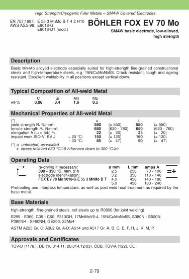
DescriptionBasic Mn-Mo alloyed electrode especially suited for high-strength fine-grained constructionalsteels and high-temperature steels, e.g. 15NiCuMoNb5S. Crack resistant, tough and ageingresistant. Excellent weldability in all positions except vertical-down.
Approvals and CertificatesTÜV-D (1178.), DB (10.014.11, 20.014.12/03), ÖBB, TÜV-A (122), CE
Base Materialshigh-strength, fine-grained steels, rail steels up to R0800 (for joint welding)
E295 - E360, C35 - C60, P310GH, 17MnMoV6-4, 15NiCuMoNb5S, S380N - S500N, P380NH - S460NH, GE300, 22Mo4
ASTM A225 Gr. C; A302 Gr. A-D; A514 und A517 Gr. A, B, C, E, F, H, J, K, M, P
Operating Datare-drying if necessary: ø mm L mm amps A300 - 350 °C, min. 2 h 2.5 250 70 - 100electrode identifikation: 3.2 350 110 - 140FOX EV 70 Mo 9018-G E 55 3 MnMo B T 4.0 450 140 - 180
5.0 450 180 - 240Preheating and interpass temperature, as well as post weld heat treatment as required by thebase metal.
Mechanical Properties of All-weld Metal(*) u syield strength Re N/mm2: 580 (≥ 550) 580 (≥ 550)tensile strength Rm N/mm2: 680 (620 - 780) 650 (620 - 760)elongation A (L0 = 5d0) %: 22 (≥ 320) 23 (≥ 320)impact work ISO-V KV J + 20 °C: 150 (≥ 120) 160 (≥ 120)
- 30 °C: 185 (≥ 347) 190 (≥ 347)(*) u untreated, as-welded
s stress relieved 650 °C/15 h/furnace down to 300 °C/air
Typical Composition of All-weld MetalC Si Mn Mo
wt-% 0.06 0.4 1.6 0.5
EN 757:1997: E 55 3 MnMo B T 4 2 H10AWS A5.5-96: E9018-G
E9018-D1 (mod.)BÖHLER FOX EV 70 Mo
SMAW basic electrode, low-alloyed, high strength
2-79
High Strength/Cryogenic Filler Metals – SMAW Covered Electrodes
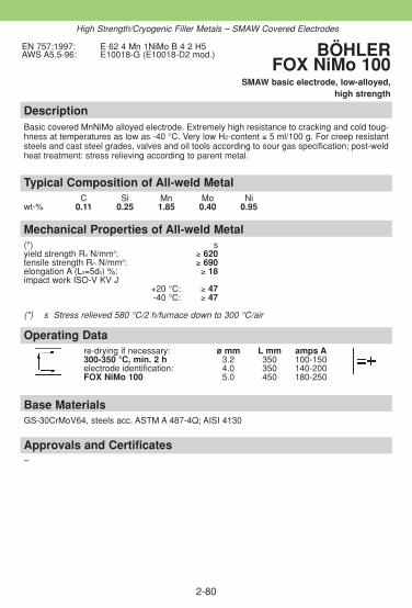
2-80
DescriptionBasic covered MnNiMo alloyed electrode. Extremely high resistance to cracking and cold toug-hness at temperatures as low as -40 °C. Very low H2-content ≤ 5 ml/100 g. For creep resistantsteels and cast steel grades, valves and oil tools according to sour gas specification; post-weldheat treatment: stress relieving according to parent metal.
Approvals and Certificates–
Base MaterialsGS-30CrMoV64, steels acc. ASTM A 487-4Q; AISI 4130
Operating Datare-drying if necessary: ø mm L mm amps A300-350 °C, min. 2 h 3.2 350 100-150electrode identification: 4.0 350 140-200FOX NiMo 100 5.0 450 180-250
Mechanical Properties of All-weld Metal(*) syield strength Re N/mm2: ≥ 620tensile strength Rm N/mm2: ≥ 690elongation A (L0=5d0) %: ≥ 18impact work ISO-V KV J
+20 °C: ≥ 47-40 °C: ≥ 47
(*) s Stress relieved 580 °C/2 h/furnace down to 300 °C/air
Typical Composition of All-weld MetalC Si Mn Mo Ni
wt-% 0.11 0.25 1.85 0.40 0.95
EN 757:1997: E 62 4 Mn 1NiMo B 4 2 H5AWS A5.5-96: E10018-G (E10018-D2 mod.) BÖHLER
FOX NiMo 100 SMAW basic electrode, low-alloyed,
high strength
High Strength/Cryogenic Filler Metals – SMAW Covered Electrodes

DescriptionMn-Mo-Ni-alloyed basic electrode with high ductility and crack resistance for high-strength, quen-ched and tempered fine-grained constructional steels. Suitable for service temperatures at -60 °C to +400 °C. Weld metal recovery approx. 120 %. Easily weldable in all positions except vertical-down.Preheat, interpass temperature and post weld heat treatment as required by the base metal. Very low hydrogen content (according AWS condition HD ≤ 4 ml/100 g weld metal).
Approvals and CertificatesSEPROZ
Base Materialsquenched and tempered fine-grained steels up to 650 N/mm2 yield strength, QT-steels up to 730 N/mm2 tensile strength
S500N, S500NH, S460NL
ASTM A225 Gr. C; A 514 and A517 Gr. A, B, C, E, F, H, J, K, M, P; A656; A678 Gr. C
Operating Datare-drying if necessary: ø mm L mm amps A300 - 350 °C, min. 2 h 3.2 350 100 - 140electrode identifikation: 4.0 450 140 - 180FOX EV 75 10018-G E 62 6 Mn2NiCrMo B
Preheating and interpass temperature, as well as post weld heat treatment as required by thebase metal.
Mechanical Properties of All-weld Metal(*) u s vyield strength Re N/mm2: 700 (≥ 650) 700 (≥ 630) 500 (≥ 430)tensile strength Rm N/mm2: 750 (730 - 850) 750 (710 - 830) 615 (550 - 670)elongation A (L0 = 5d0) %: 23 (≥ 320) 23 (≥ 320) 24 (≥ 320)impact work ISO-V KV J + 20 °C: 140 (≥ 120) 120 (≥ 370) 120 (≥ 370)
- 60 °C: (≥ 347)(*) u untreated, as-welded
s stress relieved 580 °C/2h/furnace down to 300 °C/airv quenched/tempered 910 °C/1h/air and 600 °C/2 h/furnace down to 300 °C/air
Typical Composition of All-weld MetalC Si Mn Cr Ni Mo
wt-% 0.05 0.4 1.6 0.4 2.0 0.4
EN 757:1997: E 62 6 Mn2NiCrMo B 4 2 H5AWS A5.5-96: E10018-GH4R
E10018-MH4R (mod.)BÖHLER FOX EV 75
SMAW basic electrode, low-alloyed, high strength
2-81
High Strength/Cryogenic Filler Metals – SMAW Covered Electrodes

DescriptionBasic Mn-Ni-Mo-alloyed electrode with high ductility and crack resistant for high-strength fine-grained constructional steels. Low-temperature ductility at -60 °C and resistant to ageing. Easily weldable in all positions except vertical-down. Very low hydrogen content (according AWS condition HD ≤ 4 ml/100 g weld metal).
Approvals and CertificatesTÜV-D (4313.), DB (10.014.22), ÖBB, SEPROZ, CE
Base Materialsquenched and tempered fine-grained steels up to 720 N/mm2 yield strength, quenched and tempered low-alloyed steels up to 790 N/mm2 tensile strength.
S620 QL-S690QL, S620QL1, S690QL1, N-AXTRA 56, 63, 70
Operating Datare-drying if necessary: ø mm L mm Strom 300 - 350 °C, min. 2 h 2.5 350 70 - 100electrode identifikation: 3.2 350 100 - 140FOX EV 85 11018-G E 69 6 Mn2NiCrMo B 4.0 450 140 - 180
5.0 450 190 - 230Preheat, interpass temperature and post weld heat treatment as required by the base metal.
Mechanical Properties of All-weld Metal(*) u s vyield strength Re N/mm2: 780 (≥ 720) 750 (≥ 690) 750 (≥ 650)tensile strength Rm N/mm2: 840 (790 - 960) 800 (760 - 850) 790 (730 - 860)elongation A (L0 = 5d0) %: 20 (≥ 316) 20 (≥ 316) 20 (≥ 319)impact work ISO-V KV J + 20 °C: 110 (≥ 390) 80 (≥ 360) 80 (≥ 365)
- 60 °C: 60 (≥ 347)(*) u untreated, as-welded
s stress relieved 580 °C/2 h/furnace down to 300 °C/airv quenched/tempered 920 °C/1h/air and 600 °C/2 h/furnace down to 300 °C/air
Typical Composition of All-weld MetalC Si Mn Cr Ni Mo
wt-% 0.05 0.4 1.7 0.4 2.1 0.5
EN 757:1997: E 69 6 Mn2NiCrMo B 4 2 H5AWS A5.5-96: E11018-GH4R
E11018-MH4R(mod.)BÖHLER FOX EV 85
SMAW basic electrode, low-alloyed, high strength
2-82
High Strength/Cryogenic Filler Metals – SMAW Covered Electrodes
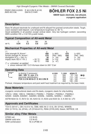
DescriptionBasic Ni-alloyed electrode for unalloyed and Ni-alloyed fine grained construction steels. Tough,crack resistant weld deposit. Low temperature toughness to -80 °C. Good weldability in all position except vertical down. Very low hydrogen content. (accordingAWS condition HD ≤ 4 ml/100 g weld metal).
Approvals and CertificatesTÜV-D (00147.), DB (10.014.16), ÖBB, ABS (Ni 2.1/2.6), BV (5Y40), WIWEB, DNV (5 YH10), GL (8Y46), LR (5Y40mH15), RINA (5YH5,3H5) Statoil, SEPROZ, CE
Base Materialscryogenic constructional steels and Ni-steels, cryogenic steels for ship building
12Ni14, 14Ni6, 10Ni14, 13MnNi6-3, P355NL1 - P460NL1, P355NL2 - P460NL2, S255N - S460N, S355NH - S460NH, S255NL - S460NL, S255NL1 - S380NL1
ASTM A633 Gr. E; A572 Gr. 65; A203 Gr. D; A333 and A334 Gr. 3; A 350 Gr. LF3
Operating Datare-drying if necessary: ø mm L mm amps A300 - 350 °C, min. 2 h 2.5 350 70 - 100electrode identifikation: 3.2 350 110 - 140FOX 2.5 Ni 8018-C1 E 46 8 2Ni B 4.0 450 140 - 180
5.0 450 190 - 230Preheat, interpass temperature and post weld heat treatment as required by the base metal.
Mechanical Properties of All-weld Metal(*) u syield strength Re N/mm2: 490 (≥ 460) 470 (≥ 420)tensile strength Rm N/mm2: 570 (550 - 680) 550 (540 - 640)elongation A (L0 = 5d0) %: 30 (≥ 324) 30 (≥ 324)impact work ISO-V KV J + 20 °C: 180 (≥ 110) 200 (≥ 110)
- 80 °C: 110 (≥ 347)(*) u untreated, as-welded
s stress relieved 580 °C/2 h/furnace down to 300 °C/air
Typical Composition of All-weld MetalC Si Mn Ni
wt-% 0.04 0.3 0.8 2.4
ENISO 2560-A:2005: E 46 8 2Ni B 42 H5AWS A5.5-96: E8018-C1H4R BÖHLER FOX 2.5 Ni
SMAW basic electrode, low-alloyed, cryogenic application
2-83
High Strength/Cryogenic Filler Metals – SMAW Covered Electrodes
Similar alloy Filler MetalsGTAW rod: 2.5 Ni-IGGMAW solid wire: 2.5 Ni-IGSAW combination: Ni 2-UP/BB 24

2-84
SM
AW
ele
ctro
de,
hig
h s
tren
gth
FO
X E
V 8
5 M
– E11
018-
MH
4R
C
0.05
Si
0.2
Mn
1.5
Cr
0.3
Mo
0.35
Ni
2.2
> 6
80 N
/mm
2
> 7
60 N
/mm
2
> 2
0 %
> 1
00 J
Bas
ic e
lect
rode
for
wel
ding
of
high
ten
sile
fine-
grai
ned
stee
ls.
Böh
ler
Des
igna
tion
Ana
lysi
s yi
eld
stre
ngth
Re
App
licat
ion
For
m
Cur
rent
, A
ppro
val
EN
757
:199
7:al
l wel
d m
etal
tens
ile s
tren
gth
Rm
Bas
e m
etal
sof
sup
ply
Wel
ding
A
WS
A5.
5-96
:w
t- %
elon
gatio
n A
ø (
mm
)
posi
tion
impa
ct w
ork
RT
3.2
/ 35
04.
0 /
450
5.0
/ 45
0
FO
X E
V 1
00E
89
4M
n2N
i1C
rMoB
42H
5
E12
018-
G
C
0.06
Si
0.35
Mn
1.7
Cr
0.7
Mo
0.5
Ni
2.5
V0.
07
>89
0 N
/mm
2
> 9
80 N
/mm
2
15 %
> 4
7 J
Bas
ic e
lect
rode
for
wel
ding
of
high
ten
sile
fine-
grai
ned
stee
ls.
Wel
d m
etal
is h
ighl
ycr
ack
resi
stan
t.
3.2
/ 35
04.
0 /
450
5.0
/ 45
0
CE
The
se e
lect
rode
s ar
e no
t re
gula
r st
ock
item
s, a
vaila
ble
an r
eque
st o
nly.

DescriptionCopper coated GTAW rod for welding in boiler, pressure vessel, pipeline, and crane construc-tion as well as in structural steel engineering. Very tough deposit of high crack resistant, non-ageing. Recommended for the temperaturerange from -30 °C to +500 °C. Good copper bonding with low total copper content. Very goodwelding and flow characteristics.
Approvals and CertificatesTÜV-D (0020.), KTA 1408.1 (8066.02), DB (42.014.09), ÖBB, TÜV-A (75), BV (UP), DNV (I YMS), FI (W MoSi), CRS (3), CE
Similar alloy Filler MetalsSMAW electrode: FOX DMO Kb SAW combination: EMS 2 Mo/BB 24
FOX DMO Ti EM2 2 Mo/BB 25GMAW solid wire: DMO-IG Gas welding rod: DMO
Base Materialssimilar alloyed high temperature steels and cast steels, ageing resistant and steels resistantto caustic cracking
S355J2G3, L290 - L415NB, L290 MB - L415MB, P255G1TH, P235GH, P265GH, P295GH,P310GH, P255NH, 16Mo3, 17MnMoV6-4, 22NiMoCr4-7, 20MnMoNi5-5, 15NiCuMoNb5S,20MnMoNi4-5, GE240 - GE300, 22Mo4, S255N - S460N, P255NH - P460NH
ASTM A335 Gr. P1; A161-94 Gr. T1 A A182M Gr. F1; A204M Gr. A, B, C; A250M Gr. T1;A217 Gr. WC1
Operating Datashielding gas: 100 % Argon ø mm
1.6rod marking: 2.0
front: WMoSi 2.4back: 1.5424 3.0
3.2Preheating, interpass temperature and post weld heat treatment as required by the base metal.
Mechanical Properties of All-weld Metal(*) u ayield strength Re N/mm2: 520 (≥ 480) 480 (≥ 400)tensile strength Rm N/mm2: 630 (570 - 720) 570 (≥ 515)elongation A (L0 = 5d0) %: 27 (≥ 323) 26 (≥ 319)impact work ISO-V KV J + 20 °C: 200 (≥ 180) 230 (≥ 200)
- 30 °C: (≥ 347)(*) u untreated, as-welded – shielding gas Argon
a annealed, 620 °C/1 h/furnace down to 300 °C/air – shielding gas Argon
Typical Composition of Welding RodC Si Mn Mo
wt-% 0.1 0.6 1.2 0.5
EN 12070:1999: W MoSiEN 1668:1997: W2Mo (for rod)EN 1668:1997: W 46 3 W2MoAWS A5.28-05: ER70S-A1 (ER80S-G)AWS A5.28M-05: ER49S-A1 (ER55S-G)W.Nr.: 1.5424
BÖHLER DMO-IGGTAW rod, low-alloyed,
high temperature, high strength
2-85
High Strength/Cryogenic Filler Metals – GTAW Rods

2-86
DescriptionNi-alloyed GTAW rod for welding of offshore pipe work and similar high integrity applications.High impact properties down to -50 °C.
Base MaterialsHigh strength steels up to S500NPipe steels: L290MB – L485MB, API Spec. 5 L: X52, X56, X60, X65,
Mechanical Properties of All-weld Metal(*) uyield strength Re N/mm2: 500 (≥ 470)tensile strength Rm N/mm2: 600 (≥ 550)elongation A (L0 = 5d0) %: 25 (≥ 24)impact work ISO-V KV J
+20 °C: 150 (≥ 47)-50 °C: 90
(*) u untreated, as-welded, shielding gas Argon
Typical Composition of Welding RodC Si Mn Ni
wt-% 0.07 0.7 1.4 0.9
EN 1668:1997: W3Ni1AWS A5.28-05: ER80S-Ni1(mod.)AWS A5.28M-05: ER55S-Ni1(mod.)
BÖHLER I 52 NiGTAW rod, low alloyed,
cryogenic application
High Strength/Cryogenic Filler Metals – GTAW Rods
Operating Datashielding gas: 100 % Argon ø mm
1.6rod marking: 2.0
front: W3Ni1 2.4back: ER80S-Ni 1 3.0
3.2Preheating, interpass temperature and post weld heat treatment as required by the base metal.
Approvals and Certificates–

DescriptionNi-alloyed copper coated GTAW rod, for unalloyed and Ni-alloyed fine grained constructionsteels. Tough, crack resistant weld deposit. Low temperature toughness to -80 °C. For thinsheets and root pass welding.
Approvals and CertificatesTÜV-D (01081.), TÜV-A (254), BV (SA 3 YM; UP), GL (6Y46), Statoil, SEPROZ, CE
Base Materialscryogenic constructional steels and Ni-steels, cryogenic steels for ship building
12Ni14, 14Ni6, 10Ni14, 13MnNi6-3, P355NL1 - P460NL1, P355NL2 - P460NL2, S255N - S460N, S355NH - S460NH, S255NL - S460NL, S255NL1 - S380NL1
ASTM A633 Gr. E; A572 Gr. 65; A203 Gr. D; A333 and A334 Gr. 3; A 350 Gr. LF3
Operating Data
shielding gas: 100 % Argon ø mmrod marking: 2.0
front: W2Ni2 2.4back: ER80S-Ni 2 3.0
Preheating, interpass temperature and post weld heat treatment as required by the base metal.
Mechanical Properties of All-weld Metal(*) uyield strength Re N/mm2: 510 (≥ 470)tensile strength Rm N/mm2: 600 (550 - 720)elongation A (L0 = 5d0) %: 26 (≥ 322)impact work ISO-V KV J + 20 °C: 280 (≥ 200)
- 60 °C: 80- 80 °C: (≥ 347)
(*) u untreated, as-welded – shielding gas Argon
Typical Composition of Welding RodC Si Mn Ni
wt-% 0.08 0.6 1.0 2.4
EN 1668:1997: W2Ni2 (for rods)EN 1668:1997: W 46 8 W2Ni2AWS A5.28-05: ER80S-Ni2AWS A5.28M-05: ER55S-Ni2
BÖHLER 2.5 Ni-IGGTAW rod, low-alloyed,
cryogenic application
2-87
Similar alloy Filler MetalsSMAW electrode: FOX 2.5 NiGMAW solid wire: 2.5 Ni-IGSAW combination: Ni 2-UP/BB 24
High Strength/Cryogenic Filler Metals – GTAW Rods
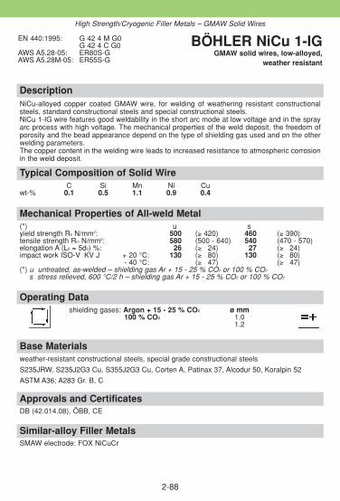
DescriptionNiCu-alloyed copper coated GMAW wire, for welding of weathering resistant constructionalsteels, standard constructional steels and special constructional steels. NiCu 1-IG wire features good weldability in the short arc mode at low voltage and in the sprayarc process with high voltage. The mechanical properties of the weld deposit, the freedom ofporosity and the bead appearance depend on the type of shielding gas used and on the otherwelding parameters. The copper content in the welding wire leads to increased resistance to atmospheric corrosionin the weld deposit.
Approvals and CertificatesDB (42.014.08), ÖBB, CE
Similar-alloy Filler MetalsSMAW electrode: FOX NiCuCr
Base Materialsweather-resistant constructional steels, special grade constructional steels
S235JRW, S235J2G3 Cu, S355J2G3 Cu, Corten A, Patinax 37, Alcodur 50, Koralpin 52
ASTM A36; A283 Gr. B, C
Operating Datashielding gases: Argon + 15 - 25 % CO2 ø mm
100 % CO2 1.01.2
Mechanical Properties of All-weld Metal(*) u syield strength Re N/mm2: 500 (≥ 420) 460 (≥ 390)tensile strength Rm N/mm2: 580 (500 - 640) 540 (470 - 570)elongation A (L0 = 5d0) %: 26 (≥ 324) 27 (≥ 324)impact work ISO-V KV J + 20 °C: 130 (≥ 380) 130 (≥ 380)
- 40 °C: (≥ 347) (≥ 347)(*) u untreated, as-welded – shielding gas Ar + 15 - 25 % CO2 or 100 % CO2
s stress relieved, 600 °C/2 h – shielding gas Ar + 15 - 25 % CO2 or 100 % CO2
Typical Composition of Solid WireC Si Mn Ni Cu
wt-% 0.1 0.5 1.1 0.9 0.4
EN 440:1995: G 42 4 M G0G 42 4 C G0
AWS A5.28-05: ER80S-GAWS A5.28M-05: ER55S-G
BÖHLER NiCu 1-IGGMAW solid wires, low-alloyed,
weather resistant
2-88
High Strength/Cryogenic Filler Metals – GMAW Solid Wires

2-89
DescriptionGMAW wire micro alloyed, designed for high quality automatic welding of pipelines. An opti-mum balanced alloying concept ensures good weld metal properties to fulfil the high require-ments in the on-offshore pipeline industry. The deposit is extremely crack resistant and the weldmetal offers high impact values down to -50 °C.
Approvals and CertificatesDNV
Base MaterialsAPI5L: X 42 – X 70 (X 80)EN 10208-2: L290MB – L485MBDIN 17172: StE290TM up to StE480.7TM
Operating DataShielding gases ø mm wireArgon +15-25 % CO2 0.9Argon +0-5 % CO2 +3-10 % O2 1.0100 % CO2 1.2
Preheating and interpass temperature as required by the base metal.
Mechanical Properties of All-weld Metal(*) u u1yield strength Re N/mm2: 500 (≥ 420) 470 (≥ 420)tensile strength Rm N/mm2: 590 (≥ 550) 560 (≥ 500)elongation A (L0 = 5d0) %: 24 (≥ 20) 25 (≥ 20)impact work ISO-V KV J + 20 °C: 150 (≥ 47) 110 (≥ 47)
- 50 °C: 80 45
(*) u untreated, as-welded shielding gas: Ar +15-25 % CO2
u1 untreated, as-welded shielding gas: 100 % CO2
Typical Composition of Solid WireC Si Mn Ni Ti
wt-% 0.06 0.70 1.50 0.90 +
EN 440:1995: G3Ni1EN 440:1995: G 42 5 M G3Ni1AWS A5.28-05: ER80S-GAWS A5.28M-05: ER55S-G
BÖHLER K NOVA NiGMAW solid wires,
low-alloyed, high strength
High Strength/Cryogenic Filler Metals – GMAW Solid Wires

DescriptionCopper coated GMAW wire for high strength, quenched and tempered fine-grained construc-tional steels.The wire is suited for joint welding in boiler, pressure vessel, pipeline, and crane constructionas well as in structural steel engineering. The typical composition of the wire fulfils the require-ments of the NORSOK-regulation for „water injection systems“.Due to the precise addition of micro alloying elements NiMo1-IG wire features excellent ductilityand crack resistance in spite of its high strength. Good cryogenic impact energy down to -60 °C,low hydrogen contents in the deposit, best feedability and low copper contents are otheradvantages of this wire.
Approvals and CertificatesDB (42.014.06), ÖBB, GL (4Y55S), SEPROZ, CE
Base Materialspipe steels and fine grained steels, quenched and tempered fine-grained steels
S380N - S500N, S380NL - S500NL, S500NC - S550NC, N-A-XTRA 56-70, BHV 70, PAS 600, HSM 600, 20MnMoNi5-5
ASTM A517 Gr. A, B, C, E, F, H, J, K, M, P; A225 Gr. C; A633 Gr. E; A572 Gr. 65API-spec 5L: X70, X80
Operating Datashielding gases: Argon + 15 - 25 % CO2 ø mmArgon + 0 - 5 % CO2 + 3 - 10 % O2 (0.9)100 % CO2 1.0
1.2Preheating and interpass temperature as required by the base metal.
Mechanical Properties of All-weld Metal(*) u u1yield strength Re N/mm2: 620 (≥ 550) 590 (≥ 550)tensile strength Rm N/mm2: 700 (650 - 800) 680 (620 - 770)elongation A (L0 = 5d0) %: 23 (≥ 320) 22 (≥ 320)impact work ISO-V KV J + 20 °C: 140 (≥ 120) 120 (≥ 100)
- 40 °C: 110 (≥ 390) (≥ 347)- 60 °C: (≥ 347)
(*) u untreated, as-welded – shielding gas Ar + 15 - 25 % CO2
u1 untreated, as-welded – shielding gas 100 % CO2
Typical Composition of Solid WireC Si Mn Mo Ni
wt-% 0.08 0.6 1.8 0.3 0.9
EN 12534:1999: Mn3Ni1Mo (for wire)EN 12534:1999: G 55 6 M Mn3Ni1Mo
G 55 4 C Mn3Ni1MoAWS A5.28-05: ER90S-GAWS A5.28M-05: ER62S-G
BÖHLER NiMo 1-IGGMAW solid wires, low-alloyed,
high strength
2-90
High Strength/Cryogenic Filler Metals – GMAW Solid Wires

DescriptionGMAW wire for joint welding of high-strength fine-grained constructional steels with stringentrequirement on low-temperature toughness down to -60 °C depending on the shielding gas.e.g. in marine engineering for the manufacture of LPG tankers.
Approvals and CertificatesDB (42.014.07), ÖBB, ABS (XYQ690X-5), BV (UP), DNV (5 Y69), GL (4Y69S), LR (X), SEPROZ, CE
Base Materialsquenched and tempered fine-grained steels with high requirements for low-temperature toughness
N-A-XTRA 65-70, USS-T 1
Operating Datashielding gases: Argon + 15 - 25 % CO2 ø mm
100 % CO2 1.01.2
Preheating and interpass temperature as required by the base metal.
Mechanical Properties of All-weld Metal(*) u u1yield strength Re N/mm2: 810 (≥ 750) 780 (≥ 720)tensile strength Rm N/mm2: 910 (830 - 980) 890 (800 - 950)elongation A (L0 = 5d0) %: 18 (≥ 316) 17 (≥ 316)impact work ISO-V KV J + 20 °C: 120 (≥ 360) 70 (≥ 350)
- 40 °C: (≥ 347)- 60 °C: (≥ 347)
(*) u untreated, as-welded – shielding gas Ar + 15 - 25 % CO2
u1 untreated, as-welded – shielding gas 100 % CO2
Typical Composition of Solid WireC Si Mn Cr Ni Mo
wt-% 0.08 0.6 1.4 0.3 2.5 0.4
EN 12534:1999: Mn3Ni2.5CrMo (for wire)EN 12534:1999: G 69 6 M Mn3Ni2.5CrMo
G 69 4 C Mn3Ni2.5CrMo AWS A5.28-05: ER110S-GAWS A5.28M-05: ER76S-G
BÖHLER NiCrMo 2.5-IG
GMAW solid wires, low-alloyed, high strength
2-91
High Strength/Cryogenic Filler Metals – GMAW Solid Wires
Similar-alloy Filler MetalsSMAW electrode: FOX EV 85SAW combination: 3NiCrMo 2.5-UP / BB 24

DescriptionGMAW wire for the welding of high-strength, heat treated, fine-grained constructional steelswith a minimum yield strength of 690 N/mm2. Due to the precise addition of micro-alloying elements X 70-IG wire features excellent ductilityand crack resistance in spite of its high strength. Good cryogenic impact energy down to -50 °C.
Approvals and CertificatesTÜV-D (5547.), DB (42.014.19), ÖBB, TÜV-A (541), ABS (X), BV (UP), DNV (IV Y69), GL (5Y69S), LR (X), RMR (4Y69), SEPROZ, CE
Base Materialshigh-strength fine-grained steels
S690Q, L690M, N-A-XTRA 70, USS-T1, BH 70 V, HY 100, Pass 700, HSM 700
ASTM A514 Gr. F
Operating Datashielding gas: Argon + 15 - 25 % CO2 ø mm
1.01.2
Preheating and interpass temperature as required by the base metal.
Mechanical Properties of All-weld Metal(*) uyield strength Re N/mm2: 800 (≥ 690)tensile strength Rm N/mm2: 900 (≥ 790)elongation A (L0 = 5d0) %: 19 (≥ 316)impact work ISO-V KV J + 20 °C: 190 (≥ 170)
- 50 °C: (≥ 347)(*) u untreated, as-welded – shielding gas Ar + 15 - 25 % CO2
Typical Composition of Solid WireC Si Mn Cr Ni Mo V
wt-% 0.1 0.6 1.6 0.25 1.3 0.25 0.1
EN 12534:1999: Mn3Ni1CrMo (for wire)EN 12534:1999: G 69 5 M Mn3Ni1CrMoAWS A5.28-05: ER110S-GAWS A5.28M-05: ER76S-G
BÖHLER X 70-IGGMAW solid wires, low-alloyed,
high strength
2-92
High Strength/Cryogenic Filler Metals – GMAW Solid Wires
Similar-alloy Filler MetalsSMAW electrode: FOX EV 85SAW combination: 3NiCrMo 2.5-UP / BB 24

DescriptionGMAW wire for the welding of higher-strength, heat treated, fine-grained constructional steelswith a minimum yield strength of 890 N/mm2. Due to the precise addition of micro-alloying elements X 90-IG wire features excellent ductilityand crack resistance in spite of its high strength. Good cryogenic impact energy down to -60 °C.
Approvals and CertificatesTÜV-D (5611.), DB (42.014.23), ÖBB, TÜV-A (616), GL (6Y89S), SEPROZ, CE
Base Materialshigh-strength fine-grained steels
S890Q, XABO 90, OX 1002
Operating Datashielding gas: Argon + 15 - 25 % CO2 ø mm
1.01.2
Preheating and interpass temperature as required by the base metal.
Mechanical Properties of All-weld Metal(*) uyield strength Re N/mm2: 915 (≥ 890)tensile strength Rm N/mm2: 960 (≥ 940)elongation A (L0 = 5d0) %: 20 (≥ 316)impact work ISO-V KV J + 20 °C: 130 (≥ 100)
- 60 °C: (≥ 347)(*) u untreated, as-welded – shielding gas Ar + 15 - 25 % CO2
Typical Composition of Solid WireC Si Mn Cr Ni Mo
wt-% 0.1 0.8 1.8 0.35 2.25 0.6
EN 12534:1999: Mn4Ni2CrMo (for wire)EN 12534:1999: G 89 6 M Mn4Ni2CrMo AWS A5.28-05: ER120S-GAWS A5.28M-05: ER83S-G
BÖHLER X 90-IGGMAW solid wires, low-alloyed,
high strength
2-93
High Strength/Cryogenic Filler Metals – GMAW Solid Wires

Description2.5 % Ni-alloyed GMAW wire for high quality welds in the construction of storage tanks andpiping systems for cryogenic applications. The weld deposit is noted for its particularly good lowtemperature an non-ageing properties down to -80 °C.
Approvals and CertificatesTÜV-D (01080.), DB (42.014.16), ÖBB, TÜV-A (732), ABS (XYQ460X-5), BV (SA 3 YM; UP), DNV (5 YMS), GL (6Y38S), LR (5Y40S H15), SEPROZ, CE
Similar alloy Filler MetalsSMAW electrode: FOX 2.5 NiGTAW rod: 2.5 Ni-IGSAW combination: Ni 2-UP/BB 24
Base Materialscryogenic constructional steels and Ni-steels, cryogenic steels for ship building
12Ni14, 14Ni6, 10Ni14, 13MnNi6-3, P355NL1 - P460NL1, P355NL2 - P460NL2, S255N - S460N, S355NH - S460NH, S255NL - S460NL, S255NL1 - S380NL1
ASTM A633 Gr. E; A572 Gr. 65; A203 Gr. D; A333 and A334 Gr. 3; A 350 Gr. LF3
Operating Datashielding gases: Argon + 15-25 % CO2 ø mm
100 % CO2 1.01.2
Preheating and interpass temperature as required by the base metal.
Mechanical Properties of All-weld Metal(*) u u1yield strength Re N/mm2: 510 (≥ 470) 500 (≥ 460)tensile strength Rm N/mm2: 600 (550 - 680) 590 (520 - 670)elongation A (L0 = 5d0) %: 22 (≥ 320) 22 (≥ 320)impact work ISO-V KV J + 20 °C: 170 (≥ 120) 120 (≥ 380)
- 60 °C: (≥ 347)- 80 °C: (≥ 347)
(*) u untreated, as-welded – shielding gas Ar + 15 - 25 % CO2
u1 untreated, as-welded – shielding gas 100 % CO2
Typical Composition of Solid WireC Si Mn Ni
wt-% 0.08 0.6 1.0 2.4
EN 440:1994: G2Ni2 (for wire)EN 440:1994: G 46 8 M G2Ni2
G 46 6 C G2Ni2AWS A5.28-05: ER80S-Ni2AWS A5.28M-05: ER55S-Ni2
BÖHLER 2.5 Ni-IGGMAW solid wires, low-alloyed,
cryogenic application
2-94
High Strength/Cryogenic Filler Metals – GMAW Solid Wires

2-95
DescriptionRutile flux-cored wire which provides easy all-position weldability and dependable mechanicalproperties down to -60 °C. The fast freezing slag provides a well supported weld pool, allowingwelding currents up to 250 A in positional welding. Because it operates in spray arc in all wel-ding positions, welding is comfortable and spatter free. Weld appearance is good, with goodtie-in. Thanks to the fast freezing slag system of BÖHLER Ti 60-FD and to good weld pool control, this flux-cored wire is particularly suited for out-of-position welding of butt and fillet joints in high strength steels with yield strength up to 460 N/mm2. The flux-cored wire iswidely used for offshore constructions, ship building and structures built with high strenghtsteels.
Approvals and CertificatesLR (DXVuBF, 4Y40SH10)
Base Materialsconstructional steels, pipe- and vessel steels, cryogenic fine-grained steels and special grades
E295, E335, S355J2G3, C35-C45, L210 - L450NB, L245MB - L450MB, P310GH, P355 NL1 -P460NL1, P355NL2 - P460NL2, S380N - S460N, P355NH-P460NH, S380NL - S460NL,S380NL1 - S460NL2, GE260-GE300
ASTM A516 Gr. 65, A572 Gr. 55, 60, 65, A633 Gr. E, A612, A618 Gr. I, A537 Gr. 1-3.
Operating Datare-drying: – ø mmshielding gas: 1.2Argon + 15 - 25 % CO2 1.6Welding with standard welding facilities.
Preheating and interpass temperature as required by the base metal.
Mechanical Properties of All-weld Metal(*) u s yield strength Re N/mm2: > 500 > 500tensile strength Rm N/mm2: > 560 > 560elongation A (L0 = 5d0) %: > 019 > 24impact work ISO-V KV J + 20 °C: > 120 >120
- 60 °C: ≥ 047 ≥ 47(*) u untreated, as-welded – shielding gas Ar + 15 - 25 % CO2
s stress relieved 620 °C/2 h/furnace down to +300 °C − shielding gas Ar + 15 - 25 % CO2
Typical Composition of All-weld MetalC Si Mn Ni
wt-% 0.06 0.45 1.2 0.85
EN 758:1997: T 50 6 1Ni P M 1 H10AWS A5.29-98: E81T1-Ni1MH8 BÖHLER Ti 60-FD
GMAW flux cored wire, low alloyed, rutile type
High Strength/Cryogenic Filler Metals – GMAW Flux Cored Wires

DescriptionWire /Flux combination for joint welding of high strength and low temperature steels.The flux reacts metallurgically Mn-neutral. The sub-arc wire/flux combination produces very good low temperature impact properties downto - 40 °C. Excellent slag detachability, smooth beads, good wetting and low hydrogen contents(≤ 5 ml/100 g) are further important features. The combination is ideally suited for multi-passwelding of thick plates.For information regarding the sub-arc welding flux BÖHLER BB 24 see our detailed data sheet.
Approvals and Certificates
TÜV-D (07807.)SAW solid wire: TÜV-D (2603.), CE
Base Materialsquenched and tempered fine-grained steels
S380N - S500N, S380NL - S500NL, S500NC - S550NC, N-A-XTRA 56-65, BHV 70, PAS600, HSM 600, 20MnMoNi5-5
ASTM A517 Gr. A, B, C, E, F, H, J, K, M, P, A225 Gr. C, A633 Gr. E, A572 Gr. 65
Operating Datare-drying of sub-arc flux: ø mm300 - 350 °C, 2 h - 10 h 4.0
Preheating and interpass temperature as required by the base metal.
Mechanical Properties of All-weld Metal(*) uyield strength Re N/mm2: 580 (≥ 560)tensile strength Rm N/mm2: 650 (620 - 720)elongation A (L0 = 5d0) %: 621 (≥ 420)impact work ISO-V KV J + 20 °C: 180 (≥ 160)
± 0 °C: 160 (≥ 140)- 20 °C: 100 (≥ 880)- 40 °C: 660 (≥ 447)
(*) u untreated, as-welded
Typical Composition of Solid Wire and All-weld MetalC Si Mn Ni Mo
Wire % 0.13 0.15 1.7 0.95 0.55Weld metal % 0.09 0.25 1.65 0.90 0.50
SAW solid wire:EN 756:2004: S 3Ni1MoAWS A5.23-97: EF3 (mod.)
sub-arc flux:EN 760:1996: SA FB 1 65 DC H5
wire/flux-combination:EN 756:2004: S 50 4 FB S 3Ni1MoAWS A5.23-97: F9A4-EF3(mod.)-F3AWS A5.23M-97: F62A4-EF3(mod.)-F3
BÖHLER 3 NiMo 1-UP//BB 24
SAW wire/flux-combination,low-alloyed, high strength
2-96
High Strength/Cryogenic Filler Metals – SAW Wire/Flux-Combinations

DescriptionWire /Flux combination for joint welding of high strength steels with a minimum yield strengthof 690 N/mm2.Depending on the annealing temperature yield strength of approx. 470-600 N/mm2 areachievable.The flux reacts metallurgically Mn-neutral. The sub-arc wire/flux combination produces very good low temperature impact properties downto -60 °C. Excellent slag detachability, smooth beads, good wetting and low hydrogen contents(≤ 5 ml/100 g). are further important features. The combination is ideally suited for multi-passwelding of thick plates.For information regarding the sub-arc welding flux BÖHLER BB 24 see our detailed data sheet.
Approvals and Certificates–
Base Materialsquenched and tempered fine-grained steels with high requirements for low-temperature impact work
N-A-XTRA 65-70, USS-T 1 etc.
Operating Datare-drying of sub-arc flux: ø mm300 - 350 °C / 2 h - 10 h 3.0
4.0
Mechanical Properties of All-weld Metal(*) uyield strength Re N/mm2: 740 (≥ 690)tensile strength Rm N/mm2: 850 (780 - 890)elongation A (L0 = 5d0) %: 20 (≥ 318)impact work ISO-V KV J + 20 °C: 120 (≥ 380)
- 20 °C: 90 (≥ 360)- 40 °C: 85- 60 °C: (≥ 347)
(*) u untreated, as-welded
Typical Composition of Solid Wire and All-weld MetalC Si Mn Cr Ni Mo
SAW wire wt-% 0.12 0.15 1.5 0.6 2.3 0.55all-welt metal % 0.06 0.3 1.5 0.50 2.2 0.50
SAW solid wire:EN 756:2004: S Z3Ni2CrMoAWS A5.23-97: EM4 (mod.)
sub-arc flux:EN 760:1996: SA FB 1 65 DC H5
wire/flux-combination:EN 756:2004: S 69 6 FB SZ3Ni2CrMoAWS A5.23-97: F11A8-EM4(mod.)-M4AWS A5.23M-97: F76A6-EM4(mod.)-M4
BÖHLER 3 NiCrMo 2.5-UP//BB 24
SAW wire/flux-combination, low-alloyed, high strength
2-97
High Strength/Cryogenic Filler Metals – SAW Wire/Flux-Combinations
Similar Alloy Filler MetalsSMAW electrode: FOX EV 85GMAW solid wire: X 70-IG
NiCrMo 2.5-IG

DescriptionThe weld deposit of the wire/flux combination (as welded and stress relieved condition) isdistinguished by excellent welding characteristic, cryogenic toughness and ageing resistancewith low hydrogen content in the deposit. Under optimum conditions (heat input below 18 kJ/cm or after stress relieving) impact strengthtransition temperature at -80 °C (ISO-V specimen) can be achieved.The flux reacts metallurgically Mn-neutral. The sub-arc wire/flux combination produces verygood low temperature impact properties down to -60 °C. Excellent slag detachability, smoothbeads, good wetting and low hydrogen contents (HD ≤ 5 ml/100 g). are further important features. The combination is ideally suited for multi-pass welding of thick plates.For information regarding the sub-arc welding flux BÖHLER BB 24 see our detailed data sheet.
Approvals and CertificatesSAW solid wire: TÜV-D (2603.), KTA 1408.1 (8058.00), DB (52.014.10), ÖBB, CETÜV-A (391), SEPROZ
Base Materialscryogenic constructional steels and Ni-steels, cryogenic steels for ship building12Ni14, 14Ni6, V10Ni14, 13MnNi6-3, P355NL1 - P460NL1, P355NL2 - P460NL2, S255N - S460N, S355NH - S460NH, S255NL - S460NL, S255NL1 - S380NL1ASTM A633 Gr. E; A572 Gr. 65; A203 Gr. D; A333 and A334 Gr. 3; A 350 Gr. LF3
Operating Datare-drying of sub-arc flux: ø mm300 - 350 °C, 2 h - 10 h 3.0
Mechanical Properties of All-weld Metal(*) uyield strength Re N/mm2: (≥ 480)tensile strength Rm N/mm2: (580 - 680)elongation A (L0 = 5d0) %: (≥ 324)impact work ISO-V KV J + 20 °C: (≥ 130)
± 0 °C: (≥ 120)- 20 °C: (≥ 100)- 60 °C: (≥ 347)
(*) u untreated, as-welded
Typical Composition of Solid Wire and All-weld MetalC Si Mn Ni
SAW wire wt-% 0.10 0.12 1.05 2.3all-weld metal % 0.07 0.25 1.15 2.2
SAW solid wire:EN 756:2004: S2Ni2AWS A5.23-97: ENi2
sub-arc flux:EN 760:1996: SA FB 1 65 DC H5
wire/flux-combination:EN 756:2004: S 46 6 FB S2Ni2AWS A5.23-97: F8A8-ENi2-Ni2AWS A5.23M-97: F55A6-ENi2-Ni2
BÖHLERNi 2-UP//BB 24
SAW wire/flux-combination,low-alloyed, cryogenic application
2-98
Similar alloy Filler MetalsSMAW electrode: FOX 2.5 Ni GMAW solid wire: 2.5 Ni-lGGTAW rod: 2.5 Ni-IG
High Strength/Cryogenic Filler Metals – SAW Wire/Flux-Combinations

2-99
Notes
2-100
Notes

2-101
2.5 Filler Metals for High Temperatureand Creep-resistant Steels
ObjectivesThis section contains detailed product information for filler metals that maybe used to weld high temperature and creep-resistant steels. The high temperature properties of general-purpose constructional steelsare no longer adequate at operating temperatures above 350 °C. Creep andflow processes occur in the steel at high temperatures under load as a resultof which the load permissible becomes time-related. Therefore steels alloy-ed with Mo, Cr-Mo and Cr-Mo-V are used. Small additions of Mo, Cr and V are sufficient up to 550 °C operating tem-perature. Above 550 °C increased scale resistance is also necessary. Up toapprox. 600 °C it is possible to use quenched and tempered 9 % and 12 %chromium steels with additions of Mo, V, Nb and W respectively. Above thistemperature special austenitic Cr-Ni steels are used. The basic type contains16 % chromium and 13 % nickel with additions of Nb. At temperatures above700 °C only nickel-base alloys with additions of Mo, W and Nb exhibitadequate creep properties. Basically the choice of the filler metals and the welding technology is alwaysin line with the parent metal used and must be matched to its behaviour.
Contents
OVERVIEW . . . . . . . . . . . . . . . . . . . . . . . . . . . . . . . . . . . . . . . . . . . . . . .102
SMAW COVERED ELECTRODES . . . . . . . . . . . . . . . . . . . . . . . . . . . . .106
GTAW RODS . . . . . . . . . . . . . . . . . . . . . . . . . . . . . . . . . . . . . . . . . . . . . .125
GMAW SOLID WIRES . . . . . . . . . . . . . . . . . . . . . . . . . . . . . . . . . . . . . . .140
GMAW METAL CORED AND FLUX CORED WIRES . . . . . . . . . . . . . . .147
SAW WIRE/FLUX-COMBINATIONS . . . . . . . . . . . . . . . . . . . . . . . . . . . .149
GAS WELDING RODS . . . . . . . . . . . . . . . . . . . . . . . . . . . . . . . . . . . . . .161
◆
◆
Product Information

2-102
Overview – Standard Classifications
Böhler EN / ENISO AWSSMAW covered electrodesFOX DMO Ti E Mo R 1 2 –
–FOX DMO Kb E Mo B 4 2 H5 A5.5-96: E7018-A1H4RFOX DCMS Ti E CrMo1 R 1 2 A5.5-96: E8013-B2(mod.)
E8013-GFOX DCMS Kb E CrMo1 B 4 2 H5 A5.5-96: E8018-B2H4RFOX DCMV E Z CrMoV1 B 4 2 H5 A5.5-96: E9018-GFOX DMV 83 Kb E MoV B 4 2 H5 A5.5-96: E9018-GFOX CM 2 Kb E CrMo2 B 4 2 H5 A5.5-96: E9018-B3H4RFOX P 23 E ZCrWV 21.5 B42 H5 A5.5-96: E9018-GFOX P 24 E ZCrMoVNbB 21 B42 H5 A5.5-96: E9018-GFOX CM 5 Kb E CrMo5 B 4 2 H5 A5.5-96: E8018-B6H4RFOX CM 9 Kb E CrMo9 B 4 2 H5 A5.5-96: E8018-B8FOX C 9 MV E CrMo91 B 4 2 H5 A5.5-96: E9015-B9FOX C 9 MVW E Z CrMoWVNb 9 1 1 B 4 2 H5 A5.5-96: E9015-B9(mod.)FOX P 92 E Z CrMoWVNb 9 0.5 2 B 4 2 H5 A5.5-96: E9015-B9(mod.)FOX 20 MVW E CrMoWV12 B 4 2 H5 –FOX CN 16/13 E Z 16 13 Nb B 4 2 H5 –FOX CN 18/11 E 19 9 B 4 2 H5 A5.4-92: E308-15FOX E 308 H E 19 9 H R 4 2 H5 A5.4-92: E308H-16FOX E 347 H E 19 9 Nb B A5.4-92: E347-15
GTAW rodsDMO-IG W Mo Si A5.28-05: ER70S-A1
ER80S-GDCMS-IG W CrMo1 Si A5.28-05: ER80S-G
ER80S-B2(mod.)DMV 83-IG W MoV Si A5.28-05: ER80S-GCM 2-IG W CrMo2 Si A5.28-05: ER90S-G
ER90S-B3(mod.)P 23-IG E ZCrWV 21.5 B42 H5 A5.28-05: ER90S-GP 24-IG W Z CrMoV 2 A5.28-05: ER90S-GCM 5-IG W CrMo5 Si A5.28-05: ER80S-B6CM 9-IG W CrMo9 Si A5.28-05: ER80S-B8C 9 MV-IG W CrMo91 A5.28-05: ER90S-B9C 9 MVW-IG W Z CrMoWVNb 9 1 1 A5.28-05: ER90S-B9(mod.)P 92-IG W Z CrMoWVNb 9 0.5 1.5 A5.28-05: ER90S-B9(mod.)20 MVW-IG W CrMoWV12 Si –CN 16/13-IG W Z 16 13 Nb –CN 18/11-IG W 19 9 H A5.9-93: ER19-10HER 308 H-IG W 19 9 H A5.9-93: ER308H
◆
High Temperature and Creep-resistant Filler Metals

Overview – Typical Chemical Composition
Böhler C Si Mn Cr Ni Mo Nb V W NSMAW covered electrodesFOX DMO Ti 0.07 0.4 0.8 0.55
FOX DMO Kb 0.08 0.35 0.8 0.45FOX DCMS Ti 0.10 0.35 0.7 1.0 0.5
FOX DCMS Kb 0.10 0.35 0.7 1.05 0.5FOX DCMV 0.12 0.3 0.9 1.3 1.0 0.22FOX DMV 83 Kb 0.065 0.35 1.2 0.4 1.0 0.5FOX CM 2 Kb 0.08 0.3 0.8 2.3 1.0FOX P 23 0.06 0.3 0.5 2.2 0.05 0.22 1.5FOX P 24 0.09 0.3 0.5 2.5 1.0 0.0045 0.22FOX CM 5 Kb 0.08 0.3 0.8 5.0 0.6FOX CM 9 Kb 0.08 0.25 0.65 9.0 1.0FOX C 9 MV 0.11 0.2 0.7 9.0 0.75 1.0 0.06 0.2FOX C 9 MVW 0.10 0.25 0.7 8.8 0.7 1.0 0.05 0.22 1.0 0.06FOX P 92 0.10 0.3 0.7 9.0 0.7 0.55 0.05 0.2 1.6 0.05FOX 20 MVW 0.18 0.3 0.7 11.0 0.55 0.9 0.25 0.5FOX CN 16/13 0.14 0.5 3.8 16.0 13.0 1.5FOX CN 18/11 0.05 0.3 1.3 19.4 10.4FOX E 308 H 0.05 0.6 0.7 19.4 10.2FOX E 347 H 0.05 0.3 1.3 19.0 10.2 ≥8xC
GTAW rodsDMO-IG 0.10 0.6 1.2 0.5
DCMS-IG 0.11 0.6 1.0 1.2 0.5
DMV 83-IG 0.08 0.6 0.9 0.45 0.85 0.35CM 2-IG 0.08 0.6 0.95 2.6 1.0
P 23-IG 0.07 0.35 0.5 2.2 0.04 0.22 1.7P 24-IG 0.10 0.25 0.5 2.5 1.0 0.05 0.24CM 5-IG 0.08 0.4 0.5 5.8 0.6CM 9-IG 0.07 0.5 0.5 9.0 1.0C 9 MV-IG 0.09 0.3 0.5 9.0 0.9 0.9 0.05 0.2C 9 MVW-IG 0.11 0.35 0.45 9.0 0.75 1.0 0.06 0.2 1.05 0.07P 92-IG 0.10 0.4 0.4 8.6 0.6 0.4 0.05 0.2 1.5 0.0520 MVW-IG 0.21 0.4 0.6 11.3 1.0 0.3 0.45CN 16/13-IG 0.16 0.6 2.5 16.0 13.5 +CN 18/11-IG 0.05 0.4 1.8 18.8 9.3ER 308 H-IG 0.06 0.4 1.7 20.0 9.5 0.2
◆
High Temperature and Creep-resistant Filler Metals
2-103

2-104
Overview – Standard Classifications (continued)
Böhler EN AWSGMAW solid wiresDMO-IG 12070: G MoSi A5.28-05: ER70S-A1
ER80S-GDCMS-IG 12070: G CrMo1Si A5.28-05: ER80S-G
ER80S-B2(mod.)DMV 83-IG 12070: G MoV Si A5.28-05: ER80S-GCM 2-IG 12070: G CrMo2 Si A5.28-05: ER90S-G
ER90S-B3(mod.) CM 5-IG 12070: G CrMo5 Si A5.28-05: ER80S-B6C 9 MV-IG 12070: G CrMo 91 A5.28-05: ER90S-B9CN 18/11-IG 12072: G 19 9 H A5.9-93: ER19-10H
GMAW metal cored and flux-cored wiresC 9 MV-MC 12070: T CRMO91 A5.28-05: EC90S-B9E 308 H-FD 17633-A: T Z 19 9 H R M 3 A5.22-95: E308HT0-4
T Z 19 9 H R C 3 E308HT0-1E 308 H PW-FD 17633-A: T Z 19 9 H P M 1 A5.22-95: E308HT1-4
T Z 19 9 H P C 1 E308HT1-1
SAW wire/flux-combinationsEMS 2 Mo 756: S 2 Mo A5.23-97: EA2EMS 2 Mo/BB 24 756: S 46 4 FB S2Mo A5.23-97: F8A4-EA2-A2
F55A4-EA2-A2EMS 2 Mo/BB 25 756: S 46 3 FB S2Mo A5.23-97: F8A4-EA2-A2
F55A4-EA2-A2EMS 2 CrMo 12070: S CrMo1 A5.23-97: EB2EMS 2 CrMo/BB 24 12070/760: S CrMo1 / SA FB 1 A5.23-97: F8P4-EB2-B2
F55P4-EB2-B2EMS 2 CrMo/BB 25 12070/760: S CrMo1 / SA FB 1 A5.23-97: F8P4-EB2-B2
F55P4-EB2-B2CM 2-UP 12070: S CrMo2 A5.23-97: EB3CM 2-UP/BB 24 12070/760: S CrMo2 / SA FB 1 A5.23-97: F9P2-EB3-B3
F55P3-EB3-B3P 23-UP 12070: S ZCrWV2 1.5 A5.23-97: EGP 23-UP/BB 430 12070:760: SA FB 1 55 AC A5.23-97: –P 24-UP 12070: S ZCrMo2VNb A5.23-97: EGP 24-UP/BB 430 12070:760: SA FB 1 55 AC A5.23-97: –CM 5-UP 12070: S CrMo5 A5.23-97: EB6CM 5-UP/BB 24 12070/760: S CrMo5 / SA FB 1 A5.23-97: F9PZ-EB6-B6
F62PZ-EB6-B6C 9 MV-UP 12070: S CrMo91 A5.23-97: EB9C 9 MV-UP/BB 910 12070/760: S CrMo91 / SA FB 2 A5.23-97: F9PZ-EB9-B9
F62PZ-EB9-B9P 92-UP 12070: S Z CrMoWVNb 9 0.5 1.5 A5.23-97: EB9(mod.)P 92-UP/BB 910 12070/760: –
S Z CrMoWVNb 9 0.5 1.5 / SA FB 220 MVW-UP 12070: S CrMoWV12 –20 MVW-UP/BB 24 12070/760: SCrMoWV12/SA FB 2 –CN 18/11-UP 12072: S 19 9 H A5.9-93: ER19-10HCN 18/11-UP/BB 202 12072/760: S 19 9 H / SA FB 2 –
Gas welding rodsDMO 12536: O IV A5.2-92: R60-GDCMS 12536: O V A5.2-92: R65-G
◆
High Temperature and Creep-resistant Filler Metals

2-105
◆
High Temperature and Creep-resistant Filler Metals
Overview – Typical Chemical Composition (continued)
Böhler C Si Mn Cr Ni Mo Nb V W NGMAW solid wiresDMO-IG 0.10 0.6 1.2 0.5
DCMS-IG 0.11 0.6 1.0 1.2 0.5
DMV 83-IG 0.08 0.6 0.9 0.45 0.85 0.35CM 2-IG 0.08 0.6 0.95 2.6 1.0
CM 5-IG 0.08 0.4 0.5 5.8 0.6C 9 MV-IG 0.12 0.3 0.5 9.0 0.7 0.9 0.055 0.2CN 18/11-IG 0.05 0.6 1.6 18.8 9.3
GMAW metal cored and flux-cored wiresC 9 MV-MC 0.1 0.3 0.6 9.0 0.7 1.0 0.05 0.2 0.04E 308 H-FD 0.05 0.6 1.2 19.4 10.1
E 308 H PW-FD 0.05 0.6 1.2 19.4 10.1
SAW wire/flux-combinationsEMS 2 Mo 0.10 0.12 1.05 0.50EMS 2 Mo/BB 24 0.07 0.25 1.15 0.45
EMS 2 Mo/BB 25 0.07 0.40 1.50 0.50
EMS 2 CrMo 0.12 0.10 0.80 1.2 0.50EMS 2 CrMo/BB 24 0.08 0.25 0.95 1.0 0.45
EMS 2 CrMo/BB 25 0.07 0.40 1.35 1.0 0.50
CM 2-UP 0.12 0.10 0.60 2.6 0.95CM 2-UP/BB 24 0.08 0.25 0.75 2.4 0.95
P 23-UP 0.07 0.35 0.5 2.2 0.05 0.22 1.7P 23-UP/BB 430 0.06 0.4 0.65 2.1 0.04 0.18 1.6P 24-UP 0.10 0.25 0.55 2.5 1.0 0.05 0.24P 24-UP/BB 430 0.08 0.30 0.75 2.4 0.95 0.05 0.20CM 5-UP 0.08 0.30 0.50 5.8 0.60CM 5-UP/BB 24 0.06 0.40 0.75 5.5 0.55
C 9 MV-UP 0.12 0.25 0.60 9.0 0.70 0.95 0.06 0.20C 9 MV-UP/BB 910 0.11 0.30 0.60 8.9 0.60 0.90 0.05 0.20
P 92-UP 0.11 0.40 0.45 8.8 0.65 0.45 0.06 0.20 1.65P 92-UP/BB 910 0.09 0.45 0.40 8.6 0.60 0.35 0.04 0.20 1.50
20 MVW-UP 0.25 0.25 0.80 11.5 0.60 0.90 0.30 0.5020 MVW-UP/BB 24 0.18 0.30 0.75 11.4 0.45 0.85 0.3 0.50CN 18/11-UP 0.05 0.40 1.60 18.8 9.30CN 18/11-UP/BB 202 0.04 0.50 1.30 18.5 9.30
Gas welding rodsDMO 0.12 0.15 1.0 0.5DCMS 0.12 0.1 0.8 1.0 0.5

DescriptionRutile electrode for 0.5 % Mo-alloyed boiler, plates, and tube steels. Approved in long- term condition up to +550 °C service temperature. Specifically preferred for thin walled weldsup to 30 mm and root pass welding. It offers excellent striking and restriking characteristics,easy slag removal, smooth beads, AC/DC weldablility and produces first class X-ray qualitywelds in all positions (except vertical down).
Approvals and CertificatesTÜV-D (0018.), DB (10.014.04), ÖBB, TÜV-A (84), BV (2YM), DNV (X), RMR (1Y), Statoil, VUZ, CE
Same Alloy Filler MetalsSMAW electrode: FOX DMO Kb SAW combination: EMS 2 Mo/BB 24GTAW rod: DMO-IG EMS 2 Mo/BB 25GMAW solid wire: DMO-lG Gas welding rod: DMOFlux cored wire: DMO Ti-FD
Base Materialshigh temperature steels and similar alloyed cast steels
16Mo3, S355J0G3, E295, P255G1TH, L320 - L415NB, L320MB - L415MB, S255N, P295GH,P310GH, P255 - P355N, P255NH - P355NH
ASTM A335 Gr. P 1; A161-94 Gr. T1; A182M Gr. F1; A204M Gr. A, B, C; A250M Gr. T1
Operating Datare-drying if necessary: ø mm L mm amps A– 2.0 250 60 - 180electrode identification: 2.5 250/350 80 - 110FOX DMO Ti E Mo R 3.2 350 110 - 140
4.0 450 140 - 180Preheating, interpass temperature, and post weld heat treatment as required by the basemetal.
Mechanical Properties of All-weld Metal(*) u ayield strength Re N/mm2: 500 (≥ 460) 470 (≥ 440)tensile strength Rm N/mm2: 570 (≥ 550) 550 (≥ 540)elongation A (L0 = 5d0) %: 23 (≥ 322) 23 (≥ 322)impact work ISO-V KV J + 20 °C: 90 (≥ 347) 100 (≥ 347)(*) u untreated, as-welded
a annealed, 620 °C/2 h/furnace down to 300 °C/air
Typical Composition of All-weld MetalC Si Mn Mo
wt-% 0.07 0.4 0.8 0.55
EN 1599:1997: E Mo R 1 2 BÖHLER FOX DMO TiSMAW rutile electrode, low-alloyed,
high temperature
2-106
High Temperature and Creep-resistant Filler Metals – SMAW Covered Electrodes

DescriptionBasic low-hydrogen electrode for 0.5 % Mo-alloyed boiler, plates, and tube steels. Approved in long-term condition up to +550 °C service temperature. For high quality welds of long term stressed components with reliable mechanical properties underhigh and low temperature conditions. Crack resistant, tough and ageing resistant. Very low hydro-gen content (acc. AWS condition HD < 4 ml/100 g). Metal recovery approx. 115 %.
Approvals and CertificatesTÜV-D (0019.), KTA 1408.1 (8053.00), DB (10.014.14), ÖBB, TÜV-A (71), ABS (E 7018-A1),DNV (NV 0,3Mo), FI (E Mo B 42 H5), GL (15 Mo 3), RMR (-), Statoil, LTSS, VUZ, SEPROZ,CRS (3YH10), CE
Same Alloy Filler MetalsSMAW electrode: FOX DMO Kb SAW combination: EMS 2 Mo/BB 24GTAW rod: DMO-IG EMS 2 Mo/BB 25GMAW solid wire: DMO-lG Gas welding rod: DMOFlux cored wire: DMO Ti-FD
Base Materialshigh temperature steels and similar alloyed cast steels, steels resistant to caustic crackingand ageing resistant steels16Mo3,S355J2G3, E295, E335, P255G1TH, L320 - L415NB, L320MB - L415MB, S255N,P295GH, P310GH, 15NiCuMoNb5, 20MnMoNi4-5, 17MnMoV6-4, S255N - S500N, S255NH - S500NH, S255NL - S500NL, GE240 - GE300, 22Mo4, GP240GHASTM A335 Gr. P1; A161-94 Gr. T1; A217 Gr. WC1; A182M Gr. F1; A204M Gr. A, B, C;A250M Gr. T1
Operating Datare-drying if necessary: ø mm L mm amps A300 - 350 °C, min. 2 h 2.5 250/350 80 - 110electrode identification: 3.2 350 100 - 140 FOX DMO Kb 7018-A1 E Mo B 4.0 350/450 130 - 180
5.0 450 190 - 230Preheat, interpass temperature, and post weld heat treatment as required by the base metal.
Mechanical Properties of All-weld Metal(*) u ayield strength Re N/mm2: 510 (≥ 480) 520 (≥ 470)tensile strength Rm N/mm2: 590 (≥ 560) 600 (≥ 560)elongation A (L0 = 5d0) %: 26 (≥ 322) 25 (≥ 322)impact work ISO-V KV J + 20 °C: 170 (≥ 120) 170 (≥ 120)
- 50 °C: 62 (≥ 332)(*) u untreated, as-welded
a annealed, 620 °C/2 h/furnace down to 300 °C/air
Typical Composition of All-weld MetalC Si Mn Mo
wt-% 0.08 0.35 0.8 0.45
EN 1599:1997: E Mo B 4 2 H5AWS A5.5-96: E7018-A1H4R BÖHLER FOX DMO Kb
SMAW basic electrode, low-alloyed, high temperature
2-107
High Temperature and Creep-resistant Filler Metals – SMAW Covered Electrodes

DescriptionRutile low hydrogen electrode for 1 % Cr 0.5 % Mo alloyed boiler, plate, and tube steels.Approved in long-term condition up to +570 °C service temperature.Easy to operate. Fully alloyed core wire. Specifically preferred for thin walled welds and rootpass welding in all positions (except vertical down). First class X-ray quality.Post weld tempering at 660-700 °C for at least 1/2 h followed by cooling in furnace down to 300 °C and still air.
Approvals and CertificatesTÜV-D (0764.), DB (10.014.05), ÖBB, TÜV-A (90), ABS (Cr 0,8/1,2 Mo), DNV (X), GL (13 CrMo 44), SEPROZ, CE
Same Alloy Filler MetalsSMAW electrode: FOX DCMS Kb SAW combination: EMS 2 CrMo/BB 24GTAW rod: DCMS-lG EMS 2 CrMo/BB 25GMAW solid wire: DCMS-lG Gas welding rod: DCMS
Base Materialshigh temperature steels and similar alloyed cast steels, case hardening and nitriding steels ofsimilar chemical composition, similar alloyed heat treatable steels with tensile strength up to780 N/mm2, steels resistant to caustic cracking.
1.7335 13CrMo4-5, 1.7205 15CrMo5, 1.7225 42CrMo4, 1.7728 16CrMoV4, 1.7218 25CrMo4,1.7258 24CrMo5, 1.7354 G22CrMo5-4, 1.7357 G17CrMo5-5
ASTM A193 Gr. B7; A335 Gr. P11 a. P12; A217 Gr. WC6
Operating Datare-drying if necessary: ø mm L mm amps A– 2.5 250 80 - 110electrode identification: 3.2 350 110 - 140FOX DCMS Ti 8013-G E CrMo1 R 4.0 350 140 - 180
Preheat and interpass temperatures of 200-250 °C are required for 13CrMo4-5 steels.
Mechanical Properties of All-weld Metal(*) ayield strength Re N/mm2: 510 (≥ 490)tensile strength Rm N/mm2: 610 (≥ 590)elongation A (L0 = 5d0) %: 21 (≥ 320)impact work ISO-V KV J + 20 °C: 100 (≥ 347)(*) a annealed, 680 °C/2 h/furnace down to 300 °C/air
Typical Composition of All-weld MetalC Si Mn Cr Mo
wt-% 0.10 0.35 0.7 1.0 0.5
EN 1599:1997: E CrMo1 R 1 2AWS A5.5-96: E8013-G
E8013-B2 (mod.)BÖHLER FOX DCMS Ti
SMAW rutile electrode, low-alloyed, high temperature
2-108
High Temperature and Creep-resistant Filler Metals – SMAW Covered Electrodes
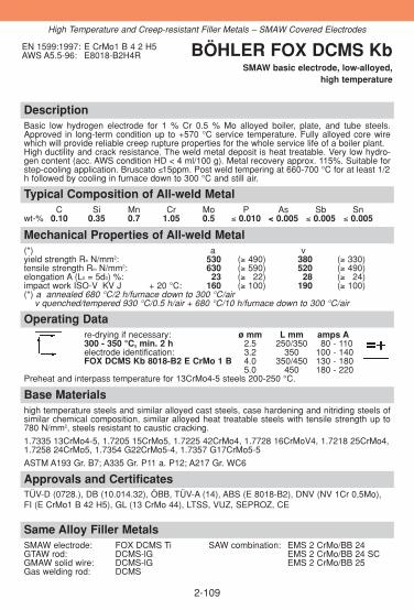
DescriptionBasic low hydrogen electrode for 1 % Cr 0.5 % Mo alloyed boiler, plate, and tube steels.Approved in long-term condition up to +570 °C service temperature. Fully alloyed core wirewhich will provide reliable creep rupture properties for the whole service life of a boiler plant.High ductility and crack resistance. The weld metal deposit is heat treatable. Very low hydro-gen content (acc. AWS condition HD < 4 ml/100 g). Metal recovery approx. 115%. Suitable forstep-cooling application. Bruscato ≤15ppm. Post weld tempering at 660-700 °C for at least 1/2h followed by cooling in furnace down to 300 °C and still air.
Approvals and CertificatesTÜV-D (0728.), DB (10.014.32), ÖBB, TÜV-A (14), ABS (E 8018-B2), DNV (NV 1Cr 0,5Mo),FI (E CrMo1 B 42 H5), GL (13 CrMo 44), LTSS, VUZ, SEPROZ, CE
Same Alloy Filler MetalsSMAW electrode: FOX DCMS Ti SAW combination: EMS 2 CrMo/BB 24GTAW rod: DCMS-lG EMS 2 CrMo/BB 24 SCGMAW solid wire: DCMS-lG EMS 2 CrMo/BB 25Gas welding rod: DCMS
Base Materialshigh temperature steels and similar alloyed cast steels, case hardening and nitriding steels ofsimilar chemical composition, similar alloyed heat treatable steels with tensile strength up to780 N/mm2, steels resistant to caustic cracking.
1.7335 13CrMo4-5, 1.7205 15CrMo5, 1.7225 42CrMo4, 1.7728 16CrMoV4, 1.7218 25CrMo4,1.7258 24CrMo5, 1.7354 G22CrMo5-4, 1.7357 G17CrMo5-5
ASTM A193 Gr. B7; A335 Gr. P11 a. P12; A217 Gr. WC6
Operating Datare-drying if necessary: ø mm L mm amps A300 - 350 °C, min. 2 h 2.5 250/350 80 - 110electrode identification: 3.2 350 100 - 140FOX DCMS Kb 8018-B2 E CrMo 1 B 4.0 350/450 130 - 180
5.0 450 180 - 220Preheat and interpass temperature for 13CrMo4-5 steels 200-250 °C.
Mechanical Properties of All-weld Metal(*) a vyield strength Re N/mm2: 530 (≥ 490) 380 (≥ 330)tensile strength Rm N/mm2: 630 (≥ 590) 520 (≥ 490)elongation A (L0 = 5d0) %: 23 (≥ 322) 28 (≥ 324)impact work ISO-V KV J + 20 °C: 160 (≥ 100) 190 (≥ 100)(*) a annealed 680 °C/2 h/furnace down to 300 °C/air
v quenched/tempered 930 °C/0.5 h/air + 680 °C/10 h/furnace down to 300 °C/air
Typical Composition of All-weld MetalC Si Mn Cr Mo P As Sb Sn
wt-% 0.10 0.35 0.7 1.05 0.5 ≤ 0.010 < 0.005 ≤ 0.005 ≤ 0.005
EN 1599:1997: E CrMo1 B 4 2 H5AWS A5.5-96: E8018-B2H4R BÖHLER FOX DCMS Kb
SMAW basic electrode, low-alloyed, high temperature
2-109
High Temperature and Creep-resistant Filler Metals – SMAW Covered Electrodes

DescriptionBasic electrode for highly stressed joint and production welds on GS-17CrMoV5-10 type hightemperature cast steel used in the construction of steam turbines and valve casings. Approvedin long-term condition up to +600 °C service temperature. High creep rupture strength thanks to the C, Cr, Mo and V-content. High fracture toughness,low hydrogen content, good welding characteristics. The deposit is heat treatable. Metal-recovery approx. 115 %.
Approvals and CertificatesTÜV-D (6077.), LTSS, SEPROZ, CE
Base Materialssimilar alloyed high temperature steels and cast steels
1.7706 G17CrMoV5-10
Operating Datare-drying if necessary: ø mm L mm amps A300 - 350 °C, min. 2 h 4.0 450 130 - 180electrode identification: 5.0 450 180 - 230FOX DCMV 9018-G E ZCrMoV1 B
Preheat and interpass temperatures 300-350 °C, stress relieving > 20 °C below the temperingtemperature of the cast steel, but not less than 680 °C.
Mechanical Properties of All-weld Metal(*) u a vyield strength Re N/mm2: 720 680 (≥ 530) 500tensile strength Rm N/mm2: 1000 770 (≥ 620) 630elongation A (L0 = 5d0) %: 12 19 (≥ 317) 20impact work ISO-V KV J + 20 °C: 22 90 (≥ 347) 155(*) u untreated, as-welded
a annealed 680 °C/8 h/furnace down to 300 °C/airv quenched/tempered 940 °C/0.5 h/oil + 720 °C/12 h/furnace down to 300 °C/air
Typical Composition of All-weld MetalC Si Mn Cr Mo V
wt-% 0.12 0.30 0.9 1.30 1.0 0.22
EN 1599:1997: E ZCrMoV1 B 4 2 H5AWS A5.5-96: E9018-G BÖHLER FOX DCMV
SMAW basic electrode, low-alloyed, high temperature
2-110
High Temperature and Creep-resistant Filler Metals – SMAW Covered Electrodes

DescriptionBasic core wire alloyed electrode with special suitability for 14MoV6-3 (1/2 Cr 1 Mo) steels.Approved in long- term condition up to +580 °C service temperature.Crack resistant and ductile deposit, low hydrogen content. Good weldability in all positionsexcept vertical down. Metal recovery approx. 115 %.
Approvals and CertificatesTÜV-D (1094.), TÜV-A (119), SEPROZ, CE
Same Alloy Filler MetalsGTAW rod: DMV 83-lGGMAW solid wire: DMV 83-IG
Base Materialssimilar alloyed high temperature steels and cast steels
1.7715 14MoV6-3, 1.7733 24CrMoV5-5, 1.7709 21CrMoV5-7, 1.8070 21CrMoV5-11, 1.7706 G17CrMoV5-10,
ASTM A389 Gr. C23 a. C24; A405 Gr. P24; UNS I21610
Operating Datare-drying if necessary: ø mm L mm amps A300 - 350 °C, min. 2 h 2.5 250 70 - 100electrode identification: 3.2 350 110 - 140FOX DMV 83 Kb 9018-G E MoV B 4.0 350 140 - 180
Preheating and interpass temperatures 200-300 °C. Post weld heat treatment at 700-720 °Cfor at least 2 hours followed by cooling in furnace down to 300 °C and still air.
Mechanical Properties of All-weld Metal(*) a vyield strength Re N/mm2: 510 (≥ 470) 410 (≥ 380)tensile strength Rm N/mm2: 660 (≥ 610) 580 (≥ 540)elongation A (L0 = 5d0) %: 22 (≥ 320) 26 (≥ 324)impact work ISO-V KV J + 20 °C: 200 (≥ 110) 150 (≥ 110)(*) a annealed 720 °C/2 h/furnace down to 300 °C/air
v quenched/tempered 940 °C/0.5 h/oil + 730 °C/0.5 h/furnace down to 300 °C/air
Typical Composition of All-weld MetalC Si Mn Cr Mo V
wt-% 0.065 0.35 1.2 0.4 1.0 0.5
EN 1599:1997: E MoV B 4 2 H5AWS A5.5-96: E9018-G BÖHLER FOX DMV 83 Kb
SMAW basic electrode, low-alloyed, high temperature
2-111
High Temperature and Creep-resistant Filler Metals – SMAW Covered Electrodes
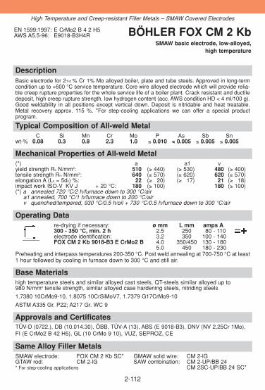
DescriptionBasic electrode for 21/4 % Cr 1% Mo alloyed boiler, plate and tube steels. Approved in long-termcondition up to +600 °C service temperature. Core wire alloyed electrode which will provide relia-ble creep rupture properties for the whole service life of a boiler plant. Crack resistant and ductiledeposit, high creep rupture strength, low hydrogen content (acc. AWS condition HD < 4 ml/100 g).Good weldability in all positions except vertical down. Deposit is nitridable and heat treatable.Metal recovery approx. 115 %. *For step-cooling applications we can offer a special product program.
Approvals and CertificatesTÜV-D (0722.), DB (10.014.30), ÖBB, TÜV-A (13), ABS (E 9018-B3), DNV (NV 2,25Cr 1Mo), FI (E CrMo2 B 42 H5), GL (10 CrMo 9 10), VUZ, SEPROZ, CE
Same Alloy Filler MetalsSMAW electrode: FOX CM 2 Kb SC* GMAW solid wire: CM 2-lGGTAW rod: CM 2-lG SAW combination: CM 2-UP/BB 24* For step-cooling applications CM 2SC-UP/BB 24 SC*
Base Materialshigh temperature steels and similar alloyed cast steels, QT-steels similar alloyed up to 980 N/mm2 tensile strength, similar alloyed case hardening steels, nitriding steels
1.7380 10CrMo9-10, 1.8075 10CrSiMoV7, 1.7379 G17CrMo9-10
ASTM A335 Gr. P22; A217 Gr. WC 9
Operating Datare-drying if necessary: ø mm L mm amps A300 - 350 °C, min. 2 h 2.5 250 80 - 110electrode identification: 3.2 350 100 - 140FOX CM 2 Kb 9018-B3 E CrMo2 B 4.0 350/450 130 - 180
5.0 450 180 - 230Preheating and interpass temperatures 200-350 °C. Post weld annealing at 700-750 °C at least1 hour followed by cooling in furnace down to 300 °C and still air.
Mechanical Properties of All-weld Metal(*) a a1 vyield strength Re N/mm2: 510 (≥ 440) (≥ 530) 480 (≥ 400)tensile strength Rm N/mm2: 640 (≥ 570) (≥ 620) 620 (≥ 570)elongation A (L0 = 5d0) %: 22 (≥ 320) (≥ 317) 21 (≥ 318)impact work ISO-V KV J + 20 °C: 180 (≥ 100) 180 (≥ 100)(*) a annealed 720 °C/2 h/furnace down to 300 °C/air
a1 annealed, 700 °C/1 h/furnace down to 200 °C/airv quenched/tempered, 930 °C/0.5 h/oil + 730 °C/0.5 h/furnace down to 300 °C/air
Typical Composition of All-weld MetalC Si Mn Cr Mo P As Sb Sn
wt-% 0.08 0.3 0.8 2.3 1.0 ≤ 0.010 < 0.005 ≤ 0.005 ≤ 0.005
EN 1599:1997: E CrMo2 B 4 2 H5AWS A5.5-96: E9018-B3H4R BÖHLER FOX CM 2 Kb
SMAW basic electrode, low-alloyed, high temperature
2-112
High Temperature and Creep-resistant Filler Metals – SMAW Covered Electrodes
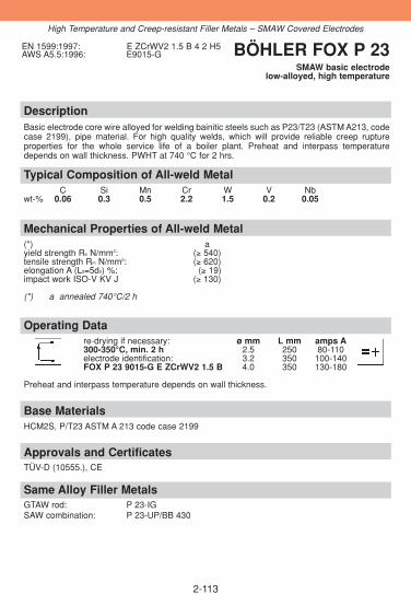
2-113
DescriptionBasic electrode core wire alloyed for welding bainitic steels such as P23/T23 (ASTM A213, codecase 2199), pipe material. For high quality welds, which will provide reliable creep rupture properties for the whole service life of a boiler plant. Preheat and interpass temperaturedepends on wall thickness. PWHT at 740 °C for 2 hrs.
Approvals and CertificatesTÜV-D (10555.), CE
Same Alloy Filler MetalsGTAW rod: P 23-IGSAW combination: P 23-UP/BB 430
Base MaterialsHCM2S, P/T23 ASTM A 213 code case 2199
Operating Datare-drying if necessary: ø mm L mm amps A300-350°C, min. 2 h 2.5 250 80-110electrode identification: 3.2 350 100-140FOX P 23 9015-G E ZCrWV2 1.5 B 4.0 350 130-180
Preheat and interpass temperature depends on wall thickness.
Mechanical Properties of All-weld Metal(*) ayield strength Re N/mm2: (≥ 540)tensile strength Rm N/mm2: (≥ 620)elongation A (L0=5d0) %: (≥ 19)impact work ISO-V KV J (≥ 130)
(*) a annealed 740°C/2 h
Typical Composition of All-weld MetalC Si Mn Cr W V Nb
wt-% 0.06 0.3 0.5 2.2 1.5 0.2 0.05
EN 1599:1997: E ZCrWV2 1.5 B 4 2 H5AWS A5.5:1996: E9015-G BÖHLER FOX P 23
SMAW basic electrodelow-alloyed, high temperature
High Temperature and Creep-resistant Filler Metals – SMAW Covered Electrodes

2-114
DescriptionBasic electrode core wire alloyed for welding bainitic steels like 7CrMoVTiB10-10 (P24/T24 acc.to ASTM A 213 Draft). For high quality welds, which will provide reliable creep rupture propertiesfor the whole service life of a boiler plant. PWHT at 740 °C for 2 hrs.
Approvals and CertificatesTÜV-D (10454.), CE
Same Alloy Filler MetalsGTAW rod: P 24-IGSAW combination: P 24-UP/BB 430
Base Materials7CrMoVTiB10-10, P24 acc. to ASTM A 213 Draft
Operating Datare-drying if necessary: ø mm L mm amps A300-350°C, min. 2 h 2.5 250 80-110electrode identification: 3.2 350 100-140FOX P 24 9018-G EZCrMo2VNbB 4.0 350 130-180
Preheat and interpass temperature depends on wall thickness.
Mechanical Properties of All-weld Metal(*) ayield strength Re N/mm2: (≥ 560)tensile strength Rm N/mm2: (≥ 660)elongation A (L0=5d0) %: (≥ 18)impact work ISO-V KV J (≥ 130)
(*) a annealed 740°C/2 h
Typical Analysis of All-weld MetalC Si Mn Cr Mo V Nb
wt-% 0.09 0.3 0.5 2.5 1.0 0.2 0.05
EN 1599:1997: E ZCrMo2VNb B 4 2 H5AWS A5.5:1996: E 9015-G BÖHLER FOX P 24
SMAW basic electrodelow-alloyed, high temperature
High Temperature and Creep-resistant Filler Metals – SMAW Covered Electrodes

DescriptionBasic core wire alloyed electrode for high temperature steels and steels for hot hydrogen servi-ce. Preferably used for X12CrMo5 (5 Cr 0.5 Mo) steels. Approved in long-term condition up to+650 °C service temperature.High crack resistance, very low hydrogen content (acc. AWS condition HD < 4 ml/100 g). Goodweldability in all positions except vertical down. The deposit is heat treatable. Metal recoveryapprox. 115 %.
Approvals and CertificatesTÜV-D (0725.), TÜV-A (695), LTSS, VUZ, SEPROZ, CE
Same Alloy Filler MetalsGTAW rod: CM 5-lGGMAW solid wire: CM 5-lGSAW combination: CM 5-UP/BB 24
Base Materialshigh temperature steels and similar alloyed cast steels, QT-steels similar alloyed up to 1180 N/mm2 tensile strength.
1.7362 X12CrMo5, 1.7363 GX12CrMo5
ASTM A213 Gr. T5; A217 Gr. C5; A335 Gr. P5
Operating Datare-drying if necessary: ø mm L mm amps A300 - 350 °C, min. 2 h 2.5 250 70 - 190electrode identification: 3.2 350 110 - 130FOX CM 5 Kb 8018-B6 E CrMo 5 B 4.0 350 140 - 170
Preheat and interpass temperatures 300-350 °C. Post weld annealing at 730-760 °C for at least1 hour followed by cooling in furnace down to 300 °C and still air.
Mechanical Properties of All-weld Metal(*) a v a2yield strength Re N/mm2: 520 (≥ 420) 440 (≥ 390) (≥ 460)tensile strength Rm N/mm2: 620 (≥ 590) 580 (≥ 570) (≥ 550)elongation A (L0 = 5d0) %: 21 (≥ 318) 26 (≥ 318) (≥ 319)impact work ISO-V KV J + 20 °C: 90 (≥ 380) 110 (≥ 380)(*) a annealed 730 °C/2 h/furnace down to 300 °C/air
a2 annealed, 760 °C/1 h/furnace down to 200 °C/airv quenched/tempered, 960 °C/0.5 h/oil + 730 °C/0.5 h/furnace down to 300 °C/air
Typical Composition of All-weld MetalC Si Mn Cr Mo
wt-% 0.08 0.3 0.8 5.0 0.6
EN 1599:1997: E CrMo5 B 4 2 H5AWS A5.5-96: E8018-B6H4R BÖHLER FOX CM 5 Kb
SMAW basic electrode, high-alloyed, high temperature
2-115
High Temperature and Creep-resistant Filler Metals – SMAW Covered Electrodes

DescriptionBasic alloyed core wire electrode for high temperature steels and steels for hot hydrogen servi-ce, particularly in the petrochemical industry. Preferably used for 9% Cr 1% Mo steels e.g.X12CrMo9-1 (P9). Approved in long-term condition up to +600 °C service temperature.The weld metal is heat treatable. Metal recovery approx. 115 %. Detailed information on welding technology available on request.
Approvals and CertificatesTÜV-D (2183.), TÜV-A (522), VUZ, SEPROZ, CE
Same Alloy Filler MetalsGTAW rod: CM 9-IG
Base Materialshighly high temperature steels, same alloyed
1.7386 X12CrMo9-1, 1.7388 X7CrMo9-1, 1.7389 GX12CrMo10
ASTM A217 Gr. C12; A 234 Gr. WP9; A335 Gr. P9
Operating Datare-drying if necessary: ø mm L mm amps A300 - 350 °C, mind. 2 h 2.5 250 70 - 190electrode identification: 3.2 350 100 - 130FOX CM 9 Kb 8018-B8 E CrMo9 B 4.0 350 130 - 160
Preheating and interpass temperatures 250-350 °C. Post weld annealing at 710-760°C for atleast 1 hr followed by cooling in furnace down to 300 °C and still air.
Mechanical Properties of All-weld Metal(*) a vyield strength Re N/mm2: 610 (≥ 550) 600 (≥ 550)tensile strength Rm N/mm2: 730 (≥ 690) 730 (≥ 690)elongation A (L0=5d0) %: 20 (≥ 319) 25 (≥ 319)impact work ISO-V KV J + 20 °C: 70 (≥ 355) 100 (≥ 355)(*) a annealed, 760 °C/1 h/furnace down to 300 °C/air
v quenched/tempered, 930 °C/10 min/air + 740 °C/2 h/air
Typical Composition of All-weld MetalC Si Mn Cr Mo
wt-% 0.08 0.25 0.65 9.0 1.0
EN 1599:1997: E CrMo9 B 4 2 H5AWS A5.5-96: E8018-B8 BÖHLER FOX CM 9 Kb
SMAW basic electrode, high-alloyed, high temperature
2-116
High Temperature and Creep-resistant Filler Metals – SMAW Covered Electrodes

DescriptionBasic core wire alloyed electrode suited for high temperature martensitic 9-12 % chromium steels, inturbine and boiler fabrication and in the chemical industry especially for T 91 and P91 steels and ope-rating temperatures up to +620 °C (approved up to +650 °C). High creep rupture strength and goodtoughness properties under long term stresses. Low hydrogen content. The electrode is suitable in allpositions except vertical down. It features excellent striking and re-striking properties.
Approvals and CertificatesTÜV-D (6762.), SEPROZ, CE
Same Alloy Filler MetalsGTAW rod: C 9 MV-IG GMAW solid wire: C 9 MV-IGGMAW wire: C 9 MV-IG GMAW metal cored wire: C 9 MV-MC
SAW combination: C 9 MV-UP/BB 910
Base Materialssimilar alloyed creep resistant steels
1.4903 X10CrMoVNb9-1
ASTM A199 Gr. T91; A335 Gr. P91 (T91); A213/213M Gr. T91
Operating Datare-drying if necessary: ø mm L mm amps A300 - 350 °C, min. 2 h 2.5 250 60 - 180electrode identification: 3.2 350 90 - 120FOX C 9 MV 9015-B9 E CrMo91 B 4.0 350 110 - 140
5.0 450 150 - 180Preheating and interpass temperature 200-300 °C. After welding the joint should be cooled down below80 °C to finish the martensite transformation. A cooling down to room temperature is possible up to awall thickness of 45 mm. In case of greater wall thickness or complex components the possibility ofresidual stresses must be considered. The following post weld heat treatment is recommended:annealing 760 °C/min. 2 hrs, max. 10 hrs, heating and cooling rates up to 550 °C max. 150 °C/h, above550 °C max. 80 °C/h. For optimised toughness values a welding technology should be applied whichproduces thin welding layers (app. 2 mm).
Mechanical Properties of All-weld Metal(*) a yield strength Re N/mm2: (≥ 550)tensile strength Rm N/mm2: (≥ 680)elongation A (L0 = 5d0) %: (≥ 17)impact work ISO-V KV J + 20 °C: (≥ 47)(*) a annealed, 760 °C/2 h/furnace down to 300 °C/air
Typical Composition of All-weld MetalC Si Mn Cr Ni Mo Nb V
wt-% 0.11 0.2 0.7 9.0 0.75 1.0 0.06 0.2
EN 1599:1997: E CrMo91 B 4 2 H5AWS A5.5-96: E9015-B9 BÖHLER FOX C 9 MV
SMAW basic electrode, high-alloyed, creep resistant
2-117
High Temperature and Creep-resistant Filler Metals – SMAW Covered Electrodes

DescriptionBasic core wire alloyed Cr-Mo-Ni-V-W-Nb-electrode for the welding of high temperature martensitic steels like e.g. X11CrMoWVNb9-1-1 (E 911, P 911). Approved in long-term condition up to +650 °C service temperature. Good welding properties in all positions exceptvertical down.
Approvals and CertificatesTÜV-D (9176.), SEPROZ, CE
Same Alloy Filler MetalsGTAW rod: C 9 MVW-IGSAW combination: C 9 MVW-UP/BB 910
Base Materialssimilar alloyed creep resistant steels
1.4905 X11CrMoWVNb9-1-1, E 911
ASTM A335 Gr. P911; A213 Gr. T911
Operating Datare-drying if necessary: ø mm L mm amps A300 - 350 °C, min. 2 h 3.2 350 90 - 120electrode identification: 4.0 350 110 - 140FOX C 9 MVW E Z CrMoWVNb 9 1 1 B 5.0 450 150 - 180
Preheating and interpass temperature 200-300 °C. After welding the joint should be cooleddown below 80 °C to finish the martensite transformation. In case of greater wall thickness orcomplex components the possibility of residual stresses must be considered.The following post weld heat treatment is recommended: annealing 760 °C/ min. 2 hrs, max.10 hrs, heating and cooling rates up to 550 °C max. 150 °C/h, above 550 °C max. 80 °C/h. For optimised toughness values a welding technology should be applied which produces thinwelding layers (app. 2 mm).
Mechanical Properties of All-weld Metal(*) a yield strength Re N/mm2: (≥ 560)tensile strength Rm N/mm2: (≥ 720)elongation A (L0 = 5d0) %: 0 (≥ 315)impact work ISO-V KV J + 20 °C: 0 (≥ 341)(*) a annealed, 760 °C/2 h/furnace down to 300 °C/air
Typical Composition of All-weld MetalC Si Mn Cr Mo Ni W V N Nb
wt-% 0.1 0.25 0.7 8.8 1.0 0.7 1.0 0.22 0.05 0.06
EN 1599:1997: E ZCrMoWVNb 9 1 1 B 4 2 H5AWS A5.5-96: E9015-B9 (mod.)
E9015-GBÖHLER
FOX C 9 MVWSMAW basic electrode, high-alloyed, creep resistant
2-118
High Temperature and Creep-resistant Filler Metals – SMAW Covered Electrodes

DescriptionBasic Cr-Mo-Ni-V-W-Nb alloyed electrode suited for welding of high temperature steel 9%Cr-1.5% W-Mo-Nb-N (NF 616, P 92). Approved in long-term condition up to + 650 °C service temperature. The elec-trode features a stable arc, good striking and re-striking properties, low spatter loss and an easy remo-vable slag.
Approvals and CertificatesTÜV-D (9291.), SEPROZ, CE
Same Alloy Filler MetalsGTAW rod: P 92-IG SAW combination: P 92-UP/BB 910
Base Materialssimilar alloyed creep resistant steels
NF 616
ASTM A335 Gr. P 92 (T92); A213 Gr. T92
Operating Datare-drying if necessary: ø mm L mm amps A300 - 350 °C, min. 2 h 3.2 350 190 - 120electrode identification: 4.0 350 110 - 140FOX P 92 E Z CrMoWVNb9 0.5 2 B
Preheating and interpass temperature 200-300 °C. After welding the joint should cool down below 80 °C,to finish the martensite transformation. In case of greater wall thickness or complex components thepossibility of residual stresses must be considered. The following postweld heat treatment is recommended: Annealing 760 °C/min. 2 hours, max. 10hours, heating/cooling rate up to 550 °C max. 150 °C/h, above 550 °C max. 80 °C/h. In case of heattreatments less than 2 hours the requirements have to be proved by a procedure test.For optimised toughness values a welding technology should be applied which produces thin weldinglayers (approx. 2 mm).
Mechanical Properties of All-weld Metal(*) a a1 a1 (650 °C test temp)yield strength Re N/mm2: 690 (≥ 560) 630 230 (≥ 125)tensile strength Rm N/mm2: 810 (≥ 720) 760 330 elongation A (L0 = 5d0) %: 19 (≥ 315) 320 322impact work ISO-V KV J + 20 °C: 55 (≥ 341) 380
0 °C: 350(*) a annealed 760 °C/2 h/furnace down to 300 °C/air
a1 annealed 760 °C/6 h/furnace down to 300 °C/air
Typical Composition of All-weld MetalC Si Mn Cr Mo Ni W V N Nb
wt-% 0.1 0.3 0.7 9.0 0.55 0.7 1.6 0.2 0.05 0.05
EN 1599:1997: E ZCrMoWVNb 9 0,5 2 B 4 2 H5AWS A5.5-96: E9015-B9 (mod.)
E9015-GBÖHLER FOX P 92SMAW basic electrode, high-alloyed,
creep resistant
2-119
High Temperature and Creep-resistant Filler Metals - SMAW Covered Electrodes

DescriptionBasic core wire alloyed electrode for high temperature, heat treatable 12 % chromium steels in turbineand boiler construction as well as in the chemical industry. Preferably used for X20CrMoV12-1. Approvedin long-term condition up to +650 °C service temperature. High creep rupture strength and excellent toughness under long term stresses. Optimum chemical com-position ensures a high quality weld metal. Low hydrogen content (HD < 5 ml/100 g). Good weldability inall positions except vertical down. The weld metal deposit is heat treatable. Metal recovery approx. 115 %.
Approvals and CertificatesTÜV-D (01082.), KTA 1408.1 (8088.00), DB (10.014.31), ÖBB, TÜV-A (81), LTSS, SEPROZ,CE
Same Alloy Filler MetalsGTAW rod: 20 MVW-IGSAW combination: 20 MVW-UP/BB 24
Base Materialssimilar alloyed creep resistant steels
1.4922 X20CrMoV12-1, 1.4935 X20CrMoWV12-1, 1.4923 X22CrMoV12-1, 1.4913 X19CrMoVNb11-1 (Turbotherm, 20 MVNb), 1.4931 GX22CrMoV12-1
Operating Datare-drying if necessary: ø mm L mm amps A300 - 350 °C, min. 2 h 2.5 250 60 - 180electrode identification: 3.2 350 90 - 120FOX 20 MVW E CrMoWV12 B 4.0 350 110 - 140
5.0 450 150 - 180Preheating and interpass temperatures 400-450 °C (austenitic welding) or 250-300 °C (martensiticwelding). Root passes should principally be welded in the martensitic range. Lower preheat andinterpass temperatures are possible, yet must be approved by practical welding tests and processqualification tests. After welding cooling down to 90±10 °C, followed by tempering at 720-760 °C for three minutes / mmwall thickness (at least for 2 hours). Quenching and tempering, if specified, at 1050 °C for 1/2 hour/oiland annealing at 760 °C for 2 hours.
Mechanical Properties of All-weld Metal(*) a vyield strength Re N/mm2: 610 (≥ 580) 590 (≥ 550)tensile strength Rm N/mm2: 800 (≥ 700) 790 (≥ 740)elongation A (L0 = 5d0) %: 18 (≥ 315) 18 (≥ 315)impact work ISO-V KV J + 20 °C: 45 (≥ 335) 45 (≥ 335)(*) a annealed 760 °C/4 h/furnace down to 300 °C/furnace down to 300 °C/air
v quenched/tempered 1050 °C/0.5 h/oil + 760 °C/2 h/furnace down to 300 °C/air
Typical Composition of All-weld MetalC Si Mn Cr Ni Mo V W
wt-% 0.18 0.3 0.7 11.0 0.55 0.9 0.25 0.5
EN 1599:1997: E CrMoWV12 B 4 2 H5 BÖHLER FOX 20 MVWSMAW basic electrode, high-alloyed,
creep resistant
2-120
High Temperature and Creep-resistant Filler Metals – SMAW Covered Electrodes

DescriptionBasic core wire alloyed electrode for high quality weld joints in high efficiency boilers and turbine components. Approved in long-term condition up to +800 °C.Fully austenitic weld deposit. Insusceptible to embrittlement and resistant to hot cracking.
Approvals and CertificatesTÜV-D (0550.), SEPROZ, CE
Base Materialssimilar alloyed creep resistant steels
1.4961 X8CrNiNb16-13, 1.4910 X3CrNiMoN17-13, 1.4981 X8CrNiMoNb16-161.4988 X8CrNiMoVNb16-13, 1.4878 X12CrNiTi18-9
Operating Datare-drying if necessary: ø mm L mm amps A250 - 300 °C, min. 2 h 2.5 250 60 - 180electrode identification: 3.2 350 80 - 110FOX CN 16/13 E Z16 13 Nb B 4.0 350 110 - 140
Preheating is not required, only in case of wall thickness above 25 mm preheat up to 150 °C.Low heat input is recommended. Interpass temperatures should not exceed 150 °C.
Mechanical Properties of All-weld Metal(*) uyield strength Re N/mm2: 450 (≥ 300)tensile strength Rm N/mm2: 600 (≥ 550)elongation A (L0 = 5d0) %: 31 (≥ 330)impact work ISO-V KV J + 20 °C: 55 (≥ 350)(*) u untreated, as-welded
Typical Composition of All-weld MetalC Si Mn Cr Ni Nb
wt-% 0.14 0.5 3.8 16.0 13.0 1.5
EN 1600: E Z16 13 Nb B 4 2 H5 BÖHLER FOX CN 16/13SMAW basic electrode, high-alloyed,
creep resistant
2-121
Same Alloy Filler MetalsGTAW rod: CN 16/13-IG
High Temperature and Creep-resistant Filler Metals – SMAW Covered Electrodes

DescriptionBasic core wire alloyed electrode with controlled delta ferrite content (3-8 FN) for austeniticCrNi steels with increased carbon contents (e.g. 1.4948 / 304H), in the boiler, reactor and tur-bine fabrication. Approved in long-term condition up to +700 °C service temperature (+300 °Cin the case of wet corrosion). Resistant to hot cracking, scaling and corrosion. Excellent welda-bility in all positions except vertical down. Also suitable for German material no. 1.4551 and no.1.4550, which are approved for temperatures up to +550 °C.
Approvals and CertificatesTÜV-D (0138.), KTA 1408.1 (8067.00), TÜV-A (447), LTSS, SEPROZ, CE
Same Alloy/Similar Alloy Filler MetalsSMAW electrode: FOX E 308 H GMAW flux cored wire: E 308 H-FDGTAW rod: ER 308 H-IG E 308 H PW-FD
CN 18/11-IG SAW combination: CN 18/11-UP/BB 202GMAW solid wire: CN 18/11-IG
Base Materialssimilar alloyed creep resistant steels
1.4948 X6CrNi18-11, 1.4949 X3CrNiN18-11AISI 304H, 321H, 347H
Operating Datare-drying if necessary: ø mm L mm amps A250 - 300 °C, min. 2 h 2.5 250 50 - 180electrode identification: 3.2 350 80 - 100FOX CN 18/11 308-15 E 19 9 B 4.0 350 110 - 140
Preheating is not required, only in case of wall thickness above 25 mm preheat up to 150 °CInterpass temperature should not exceed 200 °C.
Mechanical Properties of All-weld Metal(*) uyield strength Re N/mm2: 420 (≥ 350)tensile strength Rm N/mm2: 580 (≥ 550)elongation A (L0 = 5d0) %: 40 (≥ 335)impact work ISO-V KV J + 20 °C: 85 (≥ 370)(*) u untreated, as-welded
Typical Composition of All-weld MetalC Si Mn Cr Ni FN
wt-% 0.05 0.3 1.3 19.4 10.4 3-8
EN 1600:1997: E 19 9 B 4 2 H5AWS A5.4-92: E308-15 BÖHLER FOX CN 18/11
SMAW basic electrode, high-alloyed, creep resistant
2-122
High Temperature and Creep-resistant Filler Metals – SMAW Covered Electrodes
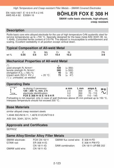
DescriptionRutile basic core wire alloyed electrode for the use of high temperature CrNi austenitic steel forservice temperatures up to +700 °C. Specially designed for the base metal AISI 304H (W. no.1.4948). Controlled ferrite content of 3-8 FN. The deposit is insusceptible to embrittlement andscaling. Excellent weldability in all position except vertical down.
Approvals and CertificatesSEPROZ
Same Alloy/Similar Alloy Filler MetalsSMAW electrode: FOX CN 18/11 GMAW flux cored wire: E 308 H-FDGTAW rod: ER 308 H-IG E 308 H PW-FD
CN 18/11-IG SAW combination: CN 18/11-UP/BB 202GMAW solid wire: CN 18/11-IG
Base Materialssimilar alloyed creep resistant steels
1.4948 X6CrNi18-11, 1.4878 X12CrNiTi18-9
AISI 304, 304H, 321H, 347H
Operating Datare-drying if necessary: ø mm L mm amps A120 - 200 °C, min. 2 h 2.5 300 45 - 175electrode identification: 3.2 350 70 - 110FOX E 308 H-16 E 19 9 H R 4.0 350 110 - 145
Preheating is not required, only in case of wall thickness above 25 mm preheat up to 150 °C,Interpass temperature should not exceed 200 °C.
Mechanical Properties of All-weld Metal(*) uyield strength Re N/mm2: 420 (≥ 350)tensile strength Rm N/mm2: 580 (≥ 550)elongation A (L0 = 5d0) %: 40 (≥ 335)impact work ISO-V KV J + 20 °C: 75 (≥ 347)(*) u untreated, as-welded
Typical Composition of All-weld MetalC Si Mn Cr Ni FN
wt-% 0.05 0.6 0.7 19.4 10.2 3-8
EN 1600:1997: E 19 9 H R 4 2 H5AWS A5.4-92: E308H-16 BÖHLER FOX E 308 H
SMAW rutile basic electrode, high-alloyed, creep resistant
2-123
High Temperature and Creep-resistant Filler Metals – SMAW Covered Electrodes

2-124
DescriptionBasic electrode core wire alloyed for the use of high temperature CrNi austenitic steel for ser-vice temperatures exceeding +400 °C. Specially designed for the base metal AISI 347H.Controlled ferrite content of 3-8 FN. The deposit is less susceptible to embrittlement and is scaling resistant. Excellent weldability an all position except vertical down.
Approvals and Certificates–
Base Materialssimilar alloyed creep resistant steelsAISI 347H, AISI 321H
Operating Datare-drying if necessary: ø mm L mm amps A– 2.5 300 50-180electrode identification: 3.2 350 75-110FOX E 347 H-15 E 19 9 Nb B 4.0 350 110-145
Mechanical Properties of All-weld Metal(*) uyield strength Re N/mm2: 470 (≥ 350)tensile strength Rm N/mm2: 630 (≥ 560)elongation A (L0=5d0) %: 36 (≥ 30)impact work ISO-V KV J +20 °C: 95
(*) u untreated, as-welded
Typical Composition of All-weld MetalC Si Mn Cr Ni Nb FN
wt-% 0.05 0.3 1.3 19.0 10.2 ≥8xC 3-8
EN 1600: 1997: E 19 9 Nb BAWS A5.4-92: E347-15 BÖHLER FOX E 347 H
SMAW basic electrodehigh-alloyed, creep resistant
High Temperature and Creep-resistant Filler Metals – SMAW Covered Electrodes

DescriptionCopper coated GTAW rod for welding in boiler, pressure vessel, pipeline, and crane construc-tion as well as in structural steel engineering. Very tough deposit of high crack resistant, non-ageing. Recommended for the temperature range from -30 °C to +500 °C. Good copper bon-ding with low total copper content. Very good welding and flow characteristics.
Approvals and CertificatesTÜV-D (0020.), KTA 1408.1 (8066.02), DB (42.014.09), ÖBB, TÜV-A (75), BV (UP), DNV (I YMS), FI (W MoSi), CRS (3), CE
Same Alloy Filler MetalsSMAW electrode: FOX DMO Kb SAW combination: EMS 2 Mo/BB 24
FOX DMO Ti EMS 2 Mo/BB 25GMAW solid wire: DMO-IG Gas welding rod: DMOFlux cored wire: DMO Ti-FD
Base Materialssimilar alloyed high temperature steels and cast steels, ageing resistant and steels resistantto caustic cracking
16Mo3, S355J2G3, L320 - L415NB, L320 MB - L415MB, P255G1TH, P235GH, P265GH,P295GH, P310GH, P255NH, 17MnMoV6-4, 22NiMoCr4-7, 20MnMoNi5-5, 15NiCuMoNb5,20MnMoNi4-5, GE240 - GE300, 22Mo4, S255N - S460N, P255NH - P460NH
ASTM A335 Gr. P1; A161-94 Gr. T1; A182M Gr. F1; A204M Gr. A, B, C; A250M Gr. T1; A217Gr. WC1
Operating Datashielding gas: 100 % Argon ø mm
1.6rod marking: 2.0
front: WMoSi 2.4back: 1.5424 3.0
3.2Preheat, interpass temperature and post weld heat treatment as required by the base metal.
Mechanical Properties of All-weld Metal(*) u ayield strength Re N/mm2: 520 (≥ 480) 480 (≥ 400)tensile strength Rm N/mm2: 630 (≥ 570) 570 (≥ 515)elongation A (L0 = 5d0) %: 27 (≥ 323) 26 (≥ 319)impact work ISO-V KV J + 20 °C: 200 (≥ 180) 230 (≥ 200)
- 30 °C: (≥ 347)(*) u untreated, as-welded – shielding gas Argon
a annealed, 620 °C/1 h/furnace down to 300 °C/air – shielding gas Argon
Typical Composition of Welding RodC Si Mn Mo
wt-% 0.1 0.6 1.2 0.5
EN 12070:1999: W MoSiEN 1668:1997: W2Mo (for rod)EN 1668:1997: W 46 3 W2MoAWS A5.28-05: ER70S-A1 (ER80S-G)AWS A5.28M-05: ER49S-A1 (ER55S-G)W.Nr.: 1.5424
BÖHLER DMO-IGGTAW rod, low-alloyed, high temperature
(high strength)
2-125
High Temperature and Creep-resistant Filler Metals – GTAW Rods

DescriptionGTAW rod for 1.25 % Cr 0.5 % Mo alloyed boiler, plate and tube steels as well as for the wel-ding of quenched and tempered and case hardening steels. Preferably used for the steels13CrMo4-5 or ASTM A335 P11/P12. Approved in long-term condition up to +570 °C service tem-perature. Suitable for step-cooling application. Bruscato ≤15ppm. The deposit is noted for itsgood mechanical properties and good toughness. Further, good resistance to cracking, whenattacked by caustic soda, and the fact that it is suitable for nitriding, quenching and temperingare additional features. The values of the creep rupture strength lay within the scatter band ofthe material 13CrMo4-5. Very good operating characteristics.
Approvals and CertificatesTÜV-D (0727.), TÜV-A (91), FI (W CrMo1Si), SEPROZ, CE
Same Alloy Filler MetalsSMAW electrode: FOX DCMS Kb SAW combination: EMS 2 CrMo/BB 24
FOX DCMS Ti EMS 2 CrMo/BB 24 SCGMAW solid wire: DCMS-IG EMS 2 CrMo/BB 25
Gas welding rod: DCMS
Base Materialssimilar alloyed high temperature steels and cast steels, case hardening and nitriding steels ofsimilar chemical composition, steels resistant to caustic cracking
1.7335 13CrMo4-5, 1.7205 15CrMo5, 1.7225 42CrMo4, 1.7728 16CrMoV4, 1.7218 25CrMo4,1.7258 24CrMo5, 1.7354 G22CrMo5-4, 1.7357 G17CrMo5-5
ASTM A193 Gr. B7; A217 Gr. WC6; A335 Gr. P11 a. P 12
Operating Datashielding gas: 100 % Argon ø mm
1.6rod marking: 2.0
front: W CrMo1 Si 2.4back: 1.7339 3.0
Preheat, interpass temperature and post weld heat treatment as required by the base metal.Preheating and interpass temperature for 13CrMo4-5 (P11/P12), 200-250 °C. Tempering at660-700 °C at least 1/2 hr followed by cooling in furnace down to 300 °C and still air.
Mechanical Properties of All-weld Metal(*) a a1yield strength Re N/mm2: 490 (≥ 440) 510 (≥ 470)tensile strength Rm N/mm2: 590 (≥ 520) 620 (≥ 550)elongation A (L0 = 5d0) %: 25 (≥ 322) 22 (≥ 19)impact work ISO-V KV J + 20 °C: 250 (≥ 347) 200a annealed, 680 °C/2 h/furnace down to 300 °C/air – shielding gas Argona1 annealed, 620 °C/1 h/furnace down to 320 °C/air – shielding gas Argon
Typical Composition of Welding RodC Si Mn Cr Mo P As Sb Sn
wt-% 0.11 0.6 1.0 1.2 0.5 ≤ 0.012 ≤ 0.010 ≤ 0.005 ≤ 0.006
EN 12070:1999: W CrMo1SiAWS A5.28-05: ER80S-G
ER80S-B2 (mod.)AWS A5.28M-05: ER55S-G (ER55S-B2 mod.)W.Nr.: 1.7339
BÖHLER DCMS-IGGTAW rod, low-alloyed, high temperature
2-126
High Temperature and Creep-resistant Filler Metals – GTAW Rods

DescriptionGTAW rod specially designed for the base metal 14MoV6-3 (1/2 Cr 1/2 Mo 1/4 V). Approved inlong-term condition up to +560 °C service temperature. Tough, cracking resistant deposit withgood creep rupture strength.
Approvals and CertificatesTÜV-D (1093.), TÜV-A (120), LTSS, SEPROZ, CE
Same Alloy Filler MetalsSMAW electrode: FOX DMV 83 KbGTAW rod: DMV 83-IGGMAW solid wire: DMV 83-IG
Base Materialssimilar alloyed high temperature steels and cast steels
1.7715 14MoV6-3, 1.7733 24CrMoV5-5, 1.7709 21CrMoV5-7, 1.8070 21CrMoV5-11, 1.7706 G17CrMoV5-10,
ASTM A389 Gr. C23 a. C24; A405 Gr. P24; UNS I21610
Operating Datashielding gas: 100 % Argon ø mm
2.4rod marking:
front: W MoVSiback: 1.5407
Preheating and interpass temperatures 200-300 °C. Tempering at 700-720 °C at least 2 hrsfollowed by cooling in furnace down to 300 °C and still air.
Mechanical Properties of All-weld Metal(*) ayield strength Re N/mm2: 520 (≥ 470)tensile strength Rm N/mm2: 670 (≥ 580)elongation A (L0 = 5d0) %: 24 (≥ 320)impact work ISO-V KV J + 20 °C: 220 (≥ 347)(*) a annealed, 700 °C/2 h/furnace down to 300 °C/air – shielding gas Argon
Typical Composition of Welding RodC Si Mn Cr Mo V
wt-% 0.08 0.6 0.9 0.45 0.85 0.35
EN 12070:1999: W MoVSiAWS A5.28-05: ER80S-GAWS A5.28M-05: ER55S-GW.Nr.: 1.5407
BÖHLER DMV 83-IGGTAW rod, low-alloyed, high temperature
2-127
High Temperature and Creep-resistant Filler Metals – GTAW Rods

DescriptionGTAW rod for 2.25 Cr 1 % Mo alloyed boiler, plate and tube steels as well as in oil refineries.Preferably used for base metal 10CrMo9-10 (ASTM A335 P22). Approved in long-termcondition up to +600 °C service temperature. Special Software for step-cooling applications is available. Also for similarly alloyed quenched and tempered steels as well as case hardeningsteels. The weld metal meets all prerequisites for reliable long term creep properties withoutembrittlement due to very low content of trace elements. Bruscato ≤ 15 ppm. Very good ope-rating characteristics. *For step-cooling applications we can offer a special product program.
Approvals and CertificatesTÜV-D (1564.), TÜV-A (89), FI (W CrMo2Si), SEPROZ, CE
Same Alloy Filler MetalsSMAW electrode: FOX CM 2 Kb GMAW solid wire: CM 2-lG
FOX CM 2 Kb SC* SAW combination: CM 2-UP/BB 24* For step-cooling application CM 2 SC-UP/BB24 SC*
Base Materialshigh temperature steels and similar alloyed cast steels, similar alloyed case hardening steels,nitriding steels
1.7380 10CrMo9-10, 1.8075 10CrSiMoV7, 1.7379 G17CrMo9-10
ASTM A335 Gr. P22; A217 Gr. WC 9
Operating Datashielding gas: 100 % Argon ø mm
1.6rod marking: 2.0
front: W CrMo2 Si 2.4back: 1.7384 3.0
Preheating and interpass temperature 200-350 °C. Tempering at 700-750 °C at least 1 hrfollowed by cooling in furnace down to 300 °C and still air.
Mechanical Properties of All-weld Metal(*) ayield strength Re N/mm2: 470 (≥ 420)tensile strength Rm N/mm2: 600 (≥ 520)elongation A (L0 = 5d0) %: 23 (≥ 322)impact work ISO-V KV J + 20 °C: 190 (≥ 347)(*) a annealed, 720 °C/2 h/furnace down to 300 °C/air – shielding gas Argon
Typical Composition of Welding RodC Si Mn Cr Mo P As Sb Sn
wt-% 0.08 0.6 0.95 2.6 1.0 ≤ 0.010 ≤ 0.010 ≤ 0.005 ≤ 0.006
EN 12070:1999: W CrMo2SiAWS A5.28-05: ER90S-G
ER90S-B3 (mod.)AWS A5.28M-05: ER62S-G
ER62S-B3 (mod.)W.Nr.: 1.7384
BÖHLER CM 2-IGGTAW rod, low-alloyed, high temperature
2-128
High Temperature and Creep-resistant Filler Metals – GTAW Rods

2-129
DescriptionFor manual or automatic GTAW-welding of creep resistant steels such as HCM2S (P23/T23acc. to ASTM A 213 code case 2199), pipe or tube material.
Approvals and CertificatesTÜV-D (10554.), CE
Same Alloy Filler MetalsSMAW electrode: FOX P 23SAW combination: P 23-UP/BB 430
Base MaterialsHCM2S, P/T23 ASTM A 213 code case 2199
Operating DataShielding gas: ø mm L mm Spools100% Argon 1.0 BS300front: T/P 23 1.2 BS300back: ER90S-G 1.6 1000
2.0 10002.4 10003.2 1000
Mechanical Properties of All-weld Metal(*) u ayield strength Re N/mm2: > 600 > 500tensile strength Rm N/mm2: > 700 > 600elongation A (L0=5d0) %: > 15 > 17impact work ISO-V KV J > 47 > 100
(*) u untreated, as-welded – shielding gas Argona annealed 740°C/2 h
Typical Composition of Welding RodC Si Mn Cr W V Nb
wt-% 0.07 0.35 0.5 2.2 1.7 0.22 0.04
EN 12070:1999: E ZCrWV2 1,5 AWS A5.28-05 ER90S-GAWS A5.28M-05 ER62S-G
BÖHLER P 23-IGGTAW rod
low-alloyed, high temperature
High Temperature and Creep-resistant Filler Metals – GTAW Rods

2-130
DescriptionFor manual or automatic GTAW-welding of creep resistant steels such as 7CrMoVTiB10-10(P24/T24 acc. to ASTM A 213 Draft), pipe or tube material.
Approvals and CertificatesTÜV (10455.), CE
Same Alloy Filler MetalsSMAW electrode: FOX P 24SAW combination: P 24-UP/BB 430
Base Materials7CrMoVTiB10-10, P24 acc. to ASTM A 213 Draft
Operating DataShielding gas: ø mm L mm Spools100% Argon 1.0 BS300rod marking: 1.2 BS300front: T/P 24 1.6 1000back: ER90S-G 2.0 1000
2.4 10003.2 1000
Preheat and interpass temperature depends on wall thickness.
Mechanical Properties of All-weld Metal(*) u ayield strength Re N/mm2: ≥ 600 ≥ 500tensile strength Rm N/mm2: ≥ 700 ≥ 600elongation A (L0=5d0) %: ≥ 15 ≥ 17impact work ISO-V KV J ≥ 47 ≥ 100
(*) u untreated, as-welded – shielding gas Argona annealed 740 °C/2 h
Typical Composition of Welding RodC Si Mn Cr Mo Nb/Ti V
wt-% 0.10 0.25 0.55 2.5 1.0 0.05 0.24
EN 12070:1999: W ZCrMo2VNbAWS A5.28-05: ER90S-GAWS A5.28M-05: ER62S-G
BÖHLER P 24-IGGTAW rod
low-alloyed, high temperature
High Temperature and Creep-resistant Filler Metals – GTAW Rods

DescriptionGTAW rod for 5 % Cr 0.5 % Mo steels and steels for hot hydrogen service, particularly forapplication in oil refineries and the base metals X12CrMo5 / P5. Approved in long-termcondition up to +650 °C service temperature.
Approvals and CertificatesTÜV-D (0724.), TÜV-A (524), SEPROZ, CE
Same Alloy Filler MetalsSMAW electrode: FOX CM 5 KbGMAW solid wire: CM 5-lGSAW combination: CM 5-UP/BB 24
Base Materialshigh temperature steels and similar alloyed cast steels
1.7362 X12CrMo5, 1.7363 GX12CrMo5
ASTM A213 Gr. T5; A217 Gr. C5; A335 Gr. P5
Operating Datashielding gas: 100 % Argon ø mm
1.6rod marking: 2.0
front: W CrMo5 Si 2.4back: ER80S-B6 3.0
Preheating and interpass temperatures 300-350 °C. Tempering at 730-760 °C at least 1 hrfollowed by cooling in furnace down to 300 °C and still air.
Mechanical Properties of All-weld Metal(*) ayield strength Re N/mm2: 510 (≥ 470)tensile strength Rm N/mm2: 620 (≥ 550)elongation A (L0 = 5d0) %: 20 (≥ 318)impact work ISO-V KV J + 20 °C: 200 (≥ 347)(*) a annealed, 730 °C/2 h/furnace down to 300 °C/air – shielding gas Argon
Typical Composition of Welding RodC Si Mn Cr Mo
wt-% 0.08 0.4 0.5 5.8 0.6
EN 12070:1999: W CrMo5SiAWS A5.28-05: ER80S-B6AWS A5.28M-05: ER55S-B6W.Nr.: 1.7373
BÖHLER CM 5-IGGTAW rod, high-alloyed, high temperature
2-131
High Temperature and Creep-resistant Filler Metals – GTAW Rods

DescriptionGTAW rod for 9 % Cr 1 % Mo high temperature steels and steels for hot hydrogen service,particularly for application in oil refineries and the base metals X12CrMo9-1 (P9). Approved inlong-term condition up to +600 °C service temperature.
Approvals and CertificatesTÜV-D (2182.), TÜV-A (523), SEPROZ, CE
Same Alloy Filler MetalsSMAW electrode: FOX CM 9 Kb
Base Materialssimilar alloyed creep resistant steels
1.7386 X12CrMo9-1, 1.7388 X7CrMo9-1, 1.7389 GX12CrMo10
ASTM A217 Gr. C12; A 234 Gr. WP9; A335 Gr. P9
Operating Datashielding gas: 100 % Argon ø mm
1.6rod marking: 2.0
front: W CrMo9 Si 2.4back: ER80S-B8
Preheating and interpass temperature 250-350 °C. Tempering at 710-760 °C for at least 1 hrfollowed by cooling in furnace down to 300 °C/air. For detailed information about the weldingtechnology please contact our service departments.
Mechanical Properties of All-weld Metal(*) ayield strength Re N/mm2: 530 (≥ 450)tensile strength Rm N/mm2: 670 (≥ 600)elongation A (L0 = 5d0) %: 24 (≥ 318)impact work ISO-V KV J + 20 °C: 250 (≥ 347)(*) a annealed, 760 °C/2 h/furnace down to 300 °C/air – shielding gas Argon
Typical Composition of Welding RodC Si Mn Cr Mo
wt-% 0.07 0.5 0.5 9.0 1.0
EN 12070:1999: W CrMo9SiAWS A5.28-05: ER80S-B8AWS A5.28M-05: ER55S-B8
BÖHLER CM 9-IGGTAW rod, high-alloyed, high temperature
2-132
High Temperature and Creep-resistant Filler Metals – GTAW Rods

Description
GTAW rod for high temperature, creep resistant martensitic 9-12 % chromium steels in turbine and boiler fabrication and in the chemical industry. Especially designed for the ASTM steels T91/P91.Approved in long-term condition up to +650 °C service temperature.
Approvals and CertificatesTÜV-D (07106.), CE
Same Alloy Filler MetalsSMAW electrode: FOX C 9 MVGMAW solid wire: C 9 MV-IGGMAW metal cored wire: C 9 MV-MCSAW combination: C 9 MV-UP/BB 910
Base Materialssimilar alloyed creep resistant steels
1.4903 X10CrMoVNb9-1
ASTM A199 Gr. T91; A335 Gr. P91; A213/213M Gr. T91
Operating Datashielding gas: 100 % Argon ø mm
2.0rod marking: 2.4
front: WCrMo91 3.0back: ER 90S-B9
Preheating and interpass temperature 200-300 °C. After welding, the weld joint should cool down below80 °C to finish the martensite transformation. In case of greater wall thickness or complex componentsthe possibility of residual stresses must be considered. The following post weld heat treatment is recom-mended: annealing 760 °C/min. 2 hrs, max. 10 hrs, heating and cooling rates below 550 °C max.150 °C/hr, above 550 °C max. 80 °C/hr. For optimised toughness values a welding technology shouldbe applied which produces thin welding layers (approx. 2 mm).
Mechanical Properties of All-weld Metal(*) ayield strength Re N/mm2: 660 (≥ 530)tensile strength Rm N/mm2: 760 (≥ 620)elongation A (L0 = 5d0) %: 17 (≥ 316)impact work ISO-V KV J + 20 °C: 55 (≥ 350)(*) a annealed, 760 °C/2 h/furnace down to 300 °C/air – shielding gas Argon
Typical Composition of Welding RodC Si Mn Cr Ni Mo V Nb
wt-% 0.12 0.3 0.5 9.0 0.7 0.9 0.2 0.055
EN 12070:1999: W CrMo91AWS A5.28-05: ER90S-B9AWS A5.28M-05: ER62S-B9W.Nr.: 1.4903
BÖHLER C 9 MV-IGGTAW rod, high-alloyed, creep resistant
2-133
High Temperature and Creep-resistant Filler Metals – GTAW Rods

2-134
DescriptionGTAW-rod for high temperature, creep resistant martensitic 9 % chromium steels, especiallydesigned for the steel E 911 and P 911. Approved in long-term condition up to +650 °C servi-ce temperature.
Approvals and CertificatesTÜV-D (9177.), CE
Same Alloy Filler MetalsSMAW electrode: FOX C 9 MVW
Base Materialssimilar alloyed creep resistant steels1.4905 X11CrMoWVNb9-1-1, ASTM A335 Gr. P911, A213 Gr. T911
Operating DataShielding gas: ø mm100 % Argon 2.0front: E 911 2.4back: –
Preheating and interpass temperature 200-300 °C. After welding the joint should be cooleddown below 80°C to finish the martensite transformation. In case of greater wall thickness orcomplex components the possibility of residual stresses must be considered. The followingpost weld heat treatment is recommended: annealing 760 °C/ min. 2 hrs, max. 10 hrs, heatingand cooling rates below 550 °C max. 150 °C/h, above 550 °C max. 80 °C/hr. For optimisedtoughness values a welding technology should be applied which produces thin welding layers(app. 2 mm).
Mechanical Properties of All-weld Metal(*) ayield strength Re N/mm2: 660 (≥ 560)tensile strength Rm N/mm2: 790 (≥ 720)elongation A (L0=5d0) %: 16 (≥ 15)impact work ISO-V KV J +20 °C: 50 (≥ 41)
(*) a annealed 760 °C/2 h/furnace down to 300 °C/air – shielding gas 100 % Argon
Typical Composition of Welding RodC Si Mn Cr Ni Mo V Nb W N
wt-% 0.11 0.35 0.45 9.0 0.75 1.0 0.2 0.06 1.05 0.04
EN 12070:1999: W ZCrMoWVNb9 1 1AWS A5.28-05: ER90S-B9 (mod.)AWS A5.28M-05: ER62S-B9 (mod.)
BÖHLER C 9 MVW-IGGTAW rod,
high-alloyed, creep resistant
High Temperature and Creep-resistant Filler Metals – GTAW Rods
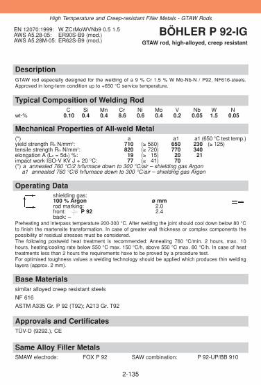
DescriptionGTAW rod especially designed for the welding of a 9 % Cr 1.5 % W Mo-Nb-N / P92, NF616-steels.Approved in long-term condition up to +650 °C service temperature.
Approvals and CertificatesTÜV-D (9292.), CE
Same Alloy Filler MetalsSMAW electrode: FOX P 92 SAW combination: P 92-UP/BB 910
Base Materialssimilar alloyed creep resistant steels
NF 616
ASTM A335 Gr. P 92 (T92); A213 Gr. T92
Operating Datashielding gas: 100 % Argon ø mmrod marking: 2.0front: P 92 2.4back: –
Preheating and interpass temperature 200-300 °C. After welding the joint should cool down below 80 °Cto finish the martensite transformation. In case of greater wall thickness or complex components thepossibility of residual stresses must be considered.The following postweld heat treatment is recommended: Annealing 760 °C/min. 2 hours, max. 10hours, heating/cooling rate below 550 °C max. 150 °C/h, above 550 °C max. 80 °C/h. In case of heattreatments less than 2 hours the requirements have to be proved by a procedure test.For optimised toughness values a welding technology should be applied which produces thin weldinglayers (approx. 2 mm).
Mechanical Properties of All-weld Metal(*) a a1 a1 (650 °C test temp.)yield strength Re N/mm2: 710 (≥ 560) 650 230 (≥ 125)tensile strength Rm N/mm2: 820 (≥ 720) 770 340 elongation A (L0 = 5d0) %: 19 (≥ 315) 320 321impact work ISO-V KV J + 20 °C: 77 (≥ 341) 370(*) a annealed 760 °C/2 h/furnace down to 300 °C/air – shielding gas Argon
a1 annealed 760 °C/6 h/furnace down to 300 °C/air – shielding gas Argon
Typical Composition of Welding RodC Si Mn Cr Ni Mo V Nb W N
wt-% 0.10 0.4 0.4 8.6 0.6 0.4 0.2 0.05 1.5 0.05
EN 12070:1999: W ZCrMoWVNb9 0.5 1.5AWS A5.28-05: ER90S-B9 (mod.)AWS A5.28M-05: ER62S-B9 (mod.)
BÖHLER P 92-IGGTAW rod, high-alloyed, creep resistant
2-135
High Temperature and Creep-resistant Filler Metals - GTAW Rods

DescriptionGTAW rod for creep resistant, quenched and tempered 12 % Cr steels in turbine and boiler fabricationand in the chemical industry. Preferably used for the base metal X20CrMoV12-1. Approved in long-termcondition up to +650 °C service temperature. The deposit exhibits high creep rupture strength and goodtoughness properties under long term stresses.
Approvals and CertificatesTÜV-D (01083.), KTA 1408.1 (8087.00), DB (42.014.24), ÖBB, TÜV-A (82), SEPROZ, CE
Same Alloy Filler MetalsSMAW electrode: FOX 20 MVW SAW combination: 20 MVW-UP/BB 24
Base Materialssimilar alloyed creep resistant steels
1.4922 X20CrMoV12-1, 1.4935 X20CrMoWV12-1, 1.4923 X22CrMoV12-11.4913 X19CrMoVNb11-1 (Turbotherm, 20 MVNb), 1.4931 GX22CrMoV12-1
Operating Datashielding gas: 100 % Argon ø mm
2.0rod marking: 2.4
front: W CrMoWV12Siback: 1.4937
Preheating and interpass temperatures 400-450 °C (austenitic welding) or 250-300 °C (martensiticwelding). Root passes should principally be welded in the martensitic range. Lower preheat andinterpass temperatures are possible, yet must be approved by practical welding tests and processqualification tests. After welding cooling down to 90±10 °C, followed by tempering at 720-760 °C forthree minutes / mm wall thickness (at least for 2 hours). Tempering, if specified, at 1050 °C for 1/2hour/oil and annealing at 760 °C for 2 hours.
Mechanical Properties of All-weld Metal(*) ayield strength Re N/mm2: 610 (≥ 590)tensile strength Rm N/mm2: 780 (≥ 700)elongation A (L0 = 5d0) %: 18 (≥ 315)impact work ISO-V KV J + 20 °C: 60 (≥ 335)(*) a annealed, 760 °C/4 h/furnace down to 300 °C/air – shielding gas Argon
Typical Composition of Welding RodC Si Mn Cr Mo V W
wt-% 0.21 0.4 0.6 11.3 1.0 0.3 0.45
EN 12070:1999: W CrMoWV12SiW.Nr: 1.4937 BÖHLER 20 MVW-IG
GTAW rod, high-alloyed, creep resistant
2-136
High Temperature and Creep-resistant Filler Metals – GTAW Rods
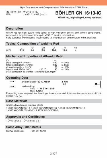
DescriptionGTAW rod for high quality weld joints in high efficiency boilers and turbine components.Approved in long-term condition up to +750 °C service temperature.Fully austenitic weld deposit. Insusceptible to embrittlement and resistant to hot cracking.
Approvals and CertificatesTÜV-D (2728.), TÜV-A (566), CE
Same Alloy Filler MetalsSMAW electrode: FOX CN 16/13
Base Materialssimilar alloyed creep resistant steels1.4961 X8CrNiNb16-13, 1.4910 X3CrNiMoN17-13, 1.4981 X8CrNiMoNb16-16,1.4988 X8CrNiMoVNb16-13, 1.4878 X12CrNiTi18-9
Operating Datashielding gas: 100 % Argon ø mm
2.0rod marking:
front: W Z 16 13 Nbback: 1.4961
Preheating is not required, low heat input is recommended, interpass temperature should notexceed 150 °C.
Mechanical Properties of All-weld Metal(*) uyield strength Re N/mm2: 460 (≥ 390)tensile strength Rm N/mm2: 630 (≥ 550)elongation A (L0 = 5d0) %: 25 (≥ 320)impact work ISO-V KV J + 20 °C: 60 (≥ 350)(*) u untreated, as-welded - shielding gas Argon
Typical Composition of Welding RodC Si Mn Cr Ni Nb
wt-% 0.16 0.6 2.5 16.0 13.5 +
EN 12072:1999: W Z 16 13 NbW.Nr: 1.4961 / 1.4948 (mod.) BÖHLER CN 16/13-IG
GTAW rod, high-alloyed, creep resistant
2-137
High Temperature and Creep-resistant Filler Metals – GTAW Rods

DescriptionGTAW rod with controlled delta ferrite content (3-8 FN) for austenitic CrNi steels with increasedcarbon contents (e.g. 1.4948 / 304H), in the boiler, reactor and turbine fabrication. Approved inlong-term condition up to +700 °C service temperature (+300 °C in the case of wet corrosion).Steels to German material no. 1.4550 and 1.4551 which are approved for the high temperatu-re range up to +550 °C, can also be welded.
Approvals and CertificatesTÜV-D (0139.), KTA 1408.1 (8068.00), TÜV-A (448), CE
Same Alloy/Similar Alloy Filler MetalsSMAW electrode: FOX E 308 H GMAW flux cored wire: E 308 H-FD
FOX CN 18/11 E 308 H PW-FDGTAW rod: ER 308 H-IG SAW combination: CN 18/11-UP/BB 202GMAW solid wire: CN 18/11-IG
Base Materialssimilar alloyed creep resistant steels
1.4948 X6CrNi18-11, 1.4949 X3CrNiN18-11
AISI 304H, 321H, 347H
Operating Datashielding gas: 100 % Argon ø mm
2.0rod marking: 2.4
front: W 19 9 H 3.0back: ER19-10H
Interpass temperature should not exceed 200 °C.
Mechanical Properties of All-weld Metal(*) uyield strength Re N/mm2: 420 (≥ 400)tensile strength Rm N/mm2: 620 (≥ 600)elongation A (L0 = 5d0) %: 40 (≥ 330)impact work ISO-V KV J + 20 °C: 150 (≥ 100)
- 10 °C: (≥ 332)(*) u untreated, as-welded – shielding gas Argon
Typical Composition of Welding RodC Si Mn Cr Ni FN
wt-% 0.05 0.4 1.6 18.8 9.3 3-8
EN 12072:1999: W 19 9 HAWS A5.9-93: ER19-10HW.Nr.: 1.4948 (mod.)
BÖHLER CN 18/11-IGGTAW rod, high-alloyed,
creep resistant
2-138
High Temperature and Creep-resistant Filler Metals – GTAW Rods

DescriptionGTAW rod for high quality joints on high temperature austenitic CrNi-steels, for service temperature up to +700 °C. Specially designed for the base metal AISI 304H (W. no. 1.4948). The controlled ferrite content ensures hot cracking resistance. The deposit is largely insusceptible to embrittlement.
Approvals and Certificates–
Same Alloy/Similar Alloy Filler MetalsSMAW electrode: FOX E 308 H GMAW flux cored wire: E 308 H-FD
FOX CN 18/11 E 308 H PW-FDGTAW rod: CN 18/11-IG SAW combination: CN 18/11-UP/BB 202GMAW solid wire: CN 18/11-lG
Base Materialssimilar alloyed creep resistant steels
1.4948 X6CrNi18-11, 1.4878 X12CrNiTi18-9
AISI 304/304H, 321H, 347H
Operating Datashielding gas: 100 % Argon ø mm
1.6rod marking: 2.0
front: ER 308 H 2.4The interpass temperature should not exceed 200 °C.
Mechanical Properties of All-weld Metal(*) uyield strength Re N/mm2: ≥ 350tensile strength Rm N/mm2: ≥ 550elongation A (L0 = 5d0) %: ≥ 335impact work ISO-V KV J + 20 °C: ≥ 370(*) u untreated, as-welded – shielding gas Argon
Typical Composition of Welding RodC Si Mn Cr Ni Mo FN
wt-% 0.06 0.4 1.7 20.0 9.5 0.2 3-8
EN 12072:1999: W 19 9 HAWS A5.9-93: ER308HW.Nr.: 1.4948 (mod.)
BÖHLER ER 308 H-IGGTAW rod, high-alloyed, creep resistant
2-139
High Temperature and Creep-resistant Filler Metals – GTAW Rods

DescriptionGMAW wire for 0.5 % Mo alloyed boiler, plate and tube steels as well as in pressure vessel andstructural steel engineering. Highly-quality, very tough deposit of high cracking resistance, non-ageing. Approved in long-term condition up to +550 °C service temperature, low temperaturetoughness to -40 °C. The wire shows good feeding and welding characteristics, resulting insmooth welding and wetting behaviour. Uniform copper bonding with low total copper content.
Approvals and CertificatesTÜV-D (0021.), DB (42.014.09), ÖBB, TÜV-A (76), FI (G MoSi), SEPROZ, CE
Same Alloy Filler MetalsSMAW electrode: FOX DMO Kb SAW combination: EMS 2 Mo/BB 24
FOX DMO Ti EMS 2 Mo/BB 25 GTAW rod: DMO-lG Gas welding rod: DMOFlux cored wire: DMO Ti-FD
Base Materialshigh temperature steels and similar alloyed cast steels, ageing resistant and steels resistantto caustic cracking
16Mo3, S355J2G3, L320 - L415NB, L320 MB - L415MB, P255G1TH, P235GH, P265GH,P295GH, P310GH, P255NH, 17MnMoV6-4, 22NiMoCr4-7, 20MnMoNi5-5, 15NiCuMoNb5,20MnMoNi4-5, GE240-GE300, 22Mo4, S255N - S460N, P255NH-P460NH
ASTM A335 Gr. P1; A161-94 Gr. T1 A A182M Gr. F1; A204M Gr. A, B, C; A250M Gr. T1;A217 Gr. WC1
Operating Datashielding gases: ø mmArgon + 15 - 25 % CO2 0.8100 % CO2 1.0
1.2Preheating, interpass temperature and post weld heat treatment as required by the base metal.
Mechanical Properties of All-weld Metal(*) u u1 ayield strength Re N/mm2: 500 (≥ 470) 470 (≥ 450) 450 (≥ 400)tensile strength Rm N/mm2: 620 (≥ 550) 590 (≥ 520) 570 (≥ 515)elongation A (L0 = 5d0) %: 25 (≥ 322) 23 (≥ 320) 25 (≥ 419)impact work ISO-V KV J + 20 °C: 150 (≥ 120) 160 150 (≥ 120)
- 40 °C: (≥ 347) (≥ 347)(*) u untreated, as-welded - shielding gas Ar + 18 % CO2
u1 untreated, as-welded - shielding gas 100 % CO2
a annealed, 620 °C/1 h/furnace down to 300 °C/air – shielding gas Ar + 18 % CO2
Typical Composition of Solid WireC Si Mn Mo
wt-% 0.1 0.6 1.2 0.5
EN 12070:1999: G MoSiAWS A5.28-05: ER70S-A1 (ER80S-G)AWS A5.28M-05: ER49S-A1 (ER55S-G)W.Nr.: 1.5424
BÖHLER DMO-IGGMAW solid wire, low-alloyed,
high temperature
2-140
High Temperature and Creep-resistant Filler Metals – GMAW Solid Wire

DescriptionGMAW wire for 1.25 % Cr 0.5 % Mo alloyed boiler, plate and tube steels as well as for thewelding of quenched and tempered and case hardening steels. Preferably used for the steels13CrMo4-5 or ASTM A335 P11/P12. Approved in long-term condition up to +570 °C servicetemperature. The deposit is noted for its good mechanical properties and good toughness.Further, good resistance to cracking, when attacked by caustic soda, and the fact that it is sui-table for nitriding, quenching and tempering are additional features. The values of the creeprupture strength lay within the scatter band of the material 13CrMo4-5. The wire shows verygood feeding characteristics, resulting in smooth welding and wetting behaviour. Uniform cop-per bonding with low total copper content.
Approvals and CertificatesTÜV-D (1091.), DB (42.014.15), ÖBB, TÜV-A (92), FI (G CrMo1Si), SEPROZ, CE
Same Alloy Filler MetalsSMAW electrode: FOX DCMS Kb SAW combination: EMS 2 CrMo/BB 24
FOX DCMS Ti EMS 2 CrMo/BB 25GTAW rod: DCMS-lG Gas welding rod: DCMS
Base Materialshigh temperature steels and similar alloyed cast steels, case hardening and nitriding steels ofsimilar chemical composition, similar alloyed heat treatable steels with tensile strength up to780 N/mm2, steels resistant to caustic cracking
1.7335 13CrMo4-5, 1.7205 15CrMo5, 1.7225 42CrMo4, 1.7728 16CrMoV4, 1.7218 25CrMo4,1.7258 24CrMo5, 1.7354 G22CrMo5-4, 1.7357 G17CrMo5-5
ASTM A193 Gr. B7; A335 Gr. P11 a. P12; A217 Gr. WC6
Operating Datashielding gases: ø mmArgon + 15 - 25 % CO2 0.8100 % CO2 1.0Using 100 % CO2 the mechanical 1.2properties can be different 1.6
Preheat, interpass temperature and post weld heat treatment as required by the base metal.Preheating and interpass temperature for 13CrMo4-5 (P11/P12), 200-250 °C. Tempering at 660-700 °C at least 1/2 hr, followed by cooling in furnace down to 300 °C and still air.
Mechanical Properties of All-weld Metal(*) ayield strength Re N/mm2: 460 (≥ 420)tensile strength Rm N/mm2: 570 (≥ 500)elongation A (L0 = 5d0) %: 23 (≥ 320)impact work ISO-V KV J + 20 °C: 150 (≥ 347)*) a annealed, 680 °C/2 h/furnace down to 300 °C/air – shielding gas Ar + 18 % CO2
Typical Composition of Solid WireC Si Mn Cr Mo
wt-% 0.11 0.6 1.0 1.2 0.5
EN 12070:1999: G CrMo1SiAWS A5.28-05: ER80S-G
ER80S-B2 (mod.)AWS A5.28M-05: ER55S-G
ER55S-B2 (mod.)W.Nr.: 1.7339
BÖHLER DCMS-IGGMAW solid wire,
low-alloyed, high temperature
2-141
High Temperature and Creep-resistant Filler Metals – GMAW Solid Wire

DescriptionGMAW wire for boiler, plate and tube steels. Designed specially for 14MoV6-3 (1/2 Cr 1/2 Mo1/4 V). Approved in long-term condition up to +560 °C service temperature. Tough, crackingresistant deposit with good creep rupture strength. The wire shows very good feeding charac-teristics, resulting in smooth welding and wetting behaviour.
Approvals and CertificatesTÜV-D (1322.), TÜV-A (121), SEPROZ, CE
Same Alloy Filler MetalsSMAW electrode: FOX DMV 83 KbGTAW rod: DMV 83-IG
Base Materialssimilar alloyed high temperature steels and cast steels
1.7715 14MoV6-3, 1.7733 24CrMoV5-5, 1.7709 21CrMoV5-7, 1.8070 21CrMoV5-11, 1.7706 G17CrMoV5-10,
ASTM A389 Gr. C23 a. C24; A405 Gr. P24; UNS I21610
Operating Datashielding gases: ø mmArgon + 15 - 25 % CO2 1.2100 % CO2
Using 100% CO2 the mechanical properties can be different.Preheating and interpass temperatures 200-300 °C. Tempering at 700-720 °C for at least 2 hrsfollowed by cooling in furnace down to 300 °C and still air.
Mechanical Properties of All-weld Metal(*) ayield strength Re N/mm2: 610 (≥ 550)tensile strength Rm N/mm2: 710 (≥ 630)elongation A (L0 = 5d0) %: 20 (≥ 318)impact work ISO-V KV J + 20 °C: 80 (≥ 347) (*) a annealed, 700 °C/2 h/furnace down to 300 °C/air – shielding gas Ar + 18 % CO2
Typical Composition of Solid WireC Si Mn Cr Mo V
wt-% 0.08 0.6 0.9 0.45 0.85 0.35
EN 12070:1999: G MoVSiAWS A5.28-05: ER80S-GAWS A5.28M-05: ER55S-GW.Nr.: 1.5407
BÖHLER DMV 83-IGGMAW solid wire,
low-alloyed, high temperature
2-142
High Temperature and Creep-resistant Filler Metals – GMAW Solid Wires
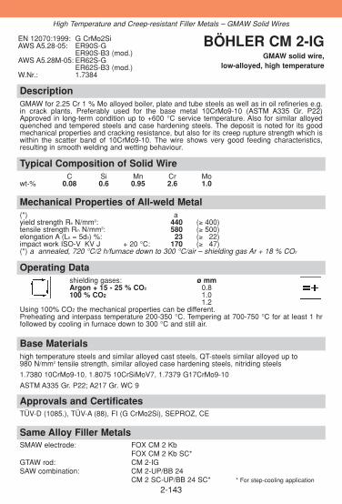
DescriptionGMAW for 2.25 Cr 1 % Mo alloyed boiler, plate and tube steels as well as in oil refineries e.g.in crack plants. Preferably used for the base metal 10CrMo9-10 (ASTM A335 Gr. P22)Approved in long-term condition up to +600 °C service temperature. Also for similar alloyedquenched and tempered steels and case hardening steels. The deposit is noted for its goodmechanical properties and cracking resistance, but also for its creep rupture strength which iswithin the scatter band of 10CrMo9-10. The wire shows very good feeding characteristics,resulting in smooth welding and wetting behaviour.
Approvals and CertificatesTÜV-D (1085.), TÜV-A (88), FI (G CrMo2Si), SEPROZ, CE
Same Alloy Filler MetalsSMAW electrode: FOX CM 2 Kb
FOX CM 2 Kb SC*GTAW rod: CM 2-IGSAW combination: CM 2-UP/BB 24
CM 2 SC-UP/BB 24 SC* * For step-cooling application
Base Materialshigh temperature steels and similar alloyed cast steels, QT-steels similar alloyed up to 980 N/mm2 tensile strength, similar alloyed case hardening steels, nitriding steels
1.7380 10CrMo9-10, 1.8075 10CrSiMoV7, 1.7379 G17CrMo9-10
ASTM A335 Gr. P22; A217 Gr. WC 9
Operating Datashielding gases: ø mmArgon + 15 - 25 % CO2 0.8100 % CO2 1.0
1.2Using 100% CO2 the mechanical properties can be different.Preheating and interpass temperature 200-350 °C. Tempering at 700-750 °C for at least 1 hrfollowed by cooling in furnace down to 300 °C and still air.
Mechanical Properties of All-weld Metal(*) ayield strength Re N/mm2: 440 (≥ 400)tensile strength Rm N/mm2: 580 (≥ 500)elongation A (L0 = 5d0) %: 23 (≥ 322)impact work ISO-V KV J + 20 °C: 170 (≥ 347)(*) a annealed, 720 °C/2 h/furnace down to 300 °C/air – shielding gas Ar + 18 % CO2
Typical Composition of Solid WireC Si Mn Cr Mo
wt-% 0.08 0.6 0.95 2.6 1.0
EN 12070:1999: G CrMo2SiAWS A5.28-05: ER90S-G
ER90S-B3 (mod.)AWS A5.28M-05: ER62S-G
ER62S-B3 (mod.)W.Nr.: 1.7384
BÖHLER CM 2-IGGMAW solid wire,
low-alloyed, high temperature
2-143
High Temperature and Creep-resistant Filler Metals – GMAW Solid Wires

DescriptionGMAW wire suitable for 5 % Cr 0.5 % Mo alloyed steels and steels for hot hydrogen service,particularly in oil refineries. Preferably used for steel grades as X12CrMo5 and P5 at servicetemperatures up to +600 °C. The wire shows very good feeding characteristics, resulting in smooth welding and flowbehaviour. Uniform copper bonding with low total copper content.
Approvals and Certificates–
Same Alloy Filler MetalsSMAW electrode: FOX CM 5 KbGTAW rod: CM 5-IGSAW combination: CM 5-UP/BB 24
Base Materialshigh temperature steels and similar alloyed cast steels, QT-steels similar alloyed up to 1180 N/mm2
1.7362 X12CrMo5, 1.7363 GX12CrMo5
ASTM A213 Gr. T5; A217 Gr. C5; A335 Gr. P5
Operating Datashielding gas: ø mmArgon + 15 - 25 % CO2 1.2
Preheating and interpass temperatures 300-350 °C. Tempering at 730-760 °C for at least 1 hrfollowed by cooling in furnace down to 300 °C and still air.
Mechanical Properties of All-weld Metal(*) ayield strength Re N/mm2: 520 (≥ 400)tensile strength Rm N/mm2: 620 (≥ 530)elongation A (L0 = 5d0) %: 20 (≥ 318)impact work ISO-V KV J + 20 °C: 200 (≥ 347)(*) a annealed, 730 °C/2 h/furnace down to 300 °C/air – shielding gas Ar + 18 % CO2
Typical Composition of Solid WireC Si Mn Cr Mo
wt-% 0.08 0.4 0.5 5.8 0.6
EN 12070:1999: G CrMo5SiAWS A5.28-05: ER80S-B6AWS A5.28M-05: ER55S-B6W.Nr.: 1.7373
BÖHLER CM 5-IGGMAW solid wire,
high-alloyed, high temperature
2-144
High Temperature and Creep-resistant Filler Metals – GMAW Solid Wires

2-145
DescriptionGMAW wire for high temperature, creep resistant martensitic 9-12 % chromium steels in turbi-ne and boiler fabrication and in the chemical industry. Especially designed for the ASTM steelsT91/P91. Approved in long-term condition up to +650 °C service temperature.
Approvals and Certificates–
Same Alloy Filler MetalsSMAW electrode: FOX C 9 MVGTAW rod: C 9 MV-IGGMAW metal cored wire: C 9 MV-MCSAW combination: C 9 MV-UP/BB 910
Base Materialssimilar alloyed creep resistant steels1.4903 X10CrMoVNb9-1ASTM A199 Gr. T91, A335 Gr. P91, A213/213M Gr. T91
Operating DataShielding gas: ø mmArgon + 2.5 % CO2 1.0
1.2
Preheating and interpass temperature 200-300 °C. After welding, the weld joint should cooldown below 80 °C to finish the martensite transformation. In case of greater wall thickness orcomplex components the possibility of residual stresses must be considered. The followingpost weld heat treatment is recommended: annealing 760 °C/min. 2 hrs, max. 10 hrs, heatingand cooling rates below 550 °C max. 150 °C/hr, above 550 °C max. 80 °C/hr. For optimisedtoughness values a welding technology should be applied which produces thin welding layers(approx. 2 mm).
Mechanical Properties of All-weld Metala
yield strength Re N/mm2: 660 (≥ 520)tensile strength Rm N/mm2: 760 (≥ 620)elongation A (L0=5d0) %: 17 (≥ 16)impact work ISO-V KV J +20 °C: 55 (≥ 50)
a annealed 760 °C/2 h/furnace down to 300 °C/air – shielding gas Argon +2.5 % CO2
Typical composition of Solid WireC Si Mn Cr Ni Mo V Nb
wt-% 0.12 0.3 0.5 9.0 0.7 0.9 0.2 0.055
EN 12070:1999: G CrMo91AWS A5.28-05: ER90S-B9AWS A5.28M-05: ER62S-B9W.Nr.: 1.4903
BÖHLER C 9 MV-IGGMAW solid wire
high-alloyed, creep resistant
High Temperature and Creep-resistant Filler Metals – GMAW Solid Wires

DescriptionGMAW wire with controlled delta ferrite content (3-8 FN) for austenitic CrNi steels with increa-sed carbon contents (e.g. 1.4948 / 304H), in the boiler, reactor and turbine fabrication.Approved in long-term condition up to +700 °C service temperature (300 °C in the case of wetcorrosion). Steels to German material no. 1.4550 and 1.4551 which are approved for the hightemperature range up to +550 °C, can also be welded.
Approvals and CertificatesTÜV-D (4466.), SEPROZ, CE
Same Alloy/Similar Alloy Filler MetalsSMAW electrode: FOX E 308 H GMAW flux cored wire: E 308 H-FD
FOX CN 18/11 E 308 H PW-FDGTAW rod: ER 308 H-lG SAW combination: CN 18/11-UP/BB 202
CN 18/11-IG
Base Materialssimilar alloyed creep resistant steels
1.4948 X6CrNi18-11, 1.4949 X3CrNiN18-11
AISI 304H, 321H, 347H
Operating Datashielding gas: ø mmArgon + max. 2.5 % CO2 1.2
Preheating is not required, only in case of wall thickness above 25 mm preheat up to 150 °C.Interpass temperature should not exceed 200 °C.
Mechanical Properties of All-weld Metal(*) uyield strength Re N/mm2: 400 (≥ 350)tensile strength Rm N/mm2: 580 (≥ 550)elongation A (L0 = 5d0) %: 38 (≥ 335)impact work ISO-V KV J + 20 °C: 120 (≥ 370)
- 10 °C: (≥ 332)(*) u untreated, as-welded – shielding gas Ar + 2.5 % CO2
Typical Composition of Solid WireC Si Mn Cr Ni FN
wt-% 0.05 0.4 1.6 18.8 9.3 3-8
EN 12072:1999: G 19 9 HAWS A5.9-93: ER19-10HW.Nr: 1.4948 (mod.)
BÖHLER CN 18/11-IGGMAW solid wire,
high-alloyed, creep resistant
2-146
High Temperature and Creep-resistant Filler Metals - GMAW Solid Wires

DescriptionMetal cored wire for high temperature, creep resistant martensitic 9-12 % chromium steels inturbine and boiler fabrication and in the chemical industry. Especially designed for the ASTM steelsT91/P91. For optimised toughness values a welding technology should be applied which pro-duces thin welding layers (approx. 2 mm), also a decisive influence on toughness values isgiven by the used shielding gas.
Approvals and Certificates–
Same Alloy/Similar Alloy Filler MetalsSMAW electrode: FOX C 9 MV GTAW rod: C 9 MV-IGSAW combination: C 9 MV-UP/BB 910 GMAW solid wire: C 9 MV-IG
Base Materialssimilar alloyed creep resistant steels
1.4903 X10CrMoVNb9-1
ASTM A199 Gr. T91, A335 Gr. P91, A213/213M Gr. T91
Operating Datashielding gases: ø mm amps A voltage VArgon + 2.5 % CO2 or 1.2 150 - 290 18 - 30Argon + 15 - 20 % CO2
Welding with conventional or pulsed power sources (preferably slightly trailing torch position, angelappr. 80 °). Recommended stick out 18 - 20 mm and length of arc 3 - 5 mm. Preheating and interpasstemperature 200-300 °C. After welding, the weld joint should cool down below 80 °C to finish the mar-tensite transformation. In case of greater wall thickness or complex components the possibility of resi-dual stresses must be considered. The following post weld heat treatment is recommended: annealing760 °C/min. 2 hrs, max. 10 hrs, heating and cooling rates below 550 °C max. 150 °C/hr, above 550 °C max. 80 °C/hr. For optimised toughness values a welding technology should be applied whichproduces thin welding layers (approx. 2 mm).
Mechanical Properties of All-weld Metala
yield strength Re N/mm2: 650 (≥ 520)tensile strength Rm N/mm2: 760 (≥ 620)elongation A (L0 = 5d0) %: 18 (≥ 317)impact work ISO-V KV J + 20 °C: 55 (≥ 347)
a annealed 760°C/3 h/furnace down to 300 °C/air – shielding gas Argon + 2.5 % CO2
Typical Composition of All-weld MetalC Si Mn Cr Ni Mo V Nb N
wt-% 0.10 0.3 0.6 9.0 0.7 1.0 0.2 0.05 0.04
ENISO 17634-B:2006: TS 69T15-1G-9C1MVAWS A5.28-05: E90C-B9AWS A5.28M-05: E62C-B9
BÖHLER C 9 MV-MCMetal cored wire,
high-alloyed, creep resistant
2-147
High Temperature and Creep-resistant Filler Metals - Metal cored wires

DescriptionBÖHLER E 308 H-FD is a flux cored wire with rutile slag characteristic for GMAW of austeniticCrNi steels like 1.4948 / AISI 304H. This wire is designed mainly for downhand and horizontalwelding positions. The weld metal is suitable for service temperatures up to approx. +700 °C.This product achieves high productivity and is easy to operate achieving excellent weldingcharacteristics, almost no spatter formation and temper discoloration, smooth weld finish andsafe penetration. Increased travel speeds as well as little demand for cleaning and picklingprovide considerable savings in time and money. The weld deposit is scaling resistant and because of the controlled low delta ferrite content highresistant against sigma phase embrittlement.
Approvals and Certificates–
Same Alloy/Similar Alloy Filler MetalsSMAW electrode: FOX CN 18/11 GMAW solid wire: CN 18/11-IG
FOX E 308 H GMAW fluxcored wire: E 308 H PW-FDGTAW rod: CN 18/11-IG SAW combination: CN 18/11-UP/BB 202
ER 308 H-IG
Base Materialssimilar alloyed creep resistant steels1.4948 X6CrNi18-11, 1.4878 X12CrNiTi18-9AISI 304, 304H, 321H, 347H
Operating Datare-drying: ø mm amps A voltage Vpossible, 150 °C / 24 h 1.2 125 - 280 20 - 34shielding gases: Argon + 15 - 25 % CO2
100 % CO2
welding with standard GMAW-facilities possible, slightly trailing torch position (angel appr. 80 °), when using 100 % CO2 as shielding gas it is necessary to increase the voltage by 2 V, gasflow should be 15-18 l/min
Mechanical Properties of All-weld Metal(*) u u/500 °Cyield strength Re N/mm2: 390 (≥ 350) 310tensile strength Rm N/mm2: 585 (≥ 550) 440elongation A (L0 = 5d0) %: 42 (≥ 335) 330impact work ISO-V KV J + 20 °C: 80 (≥ 347)(*) u untreated, as-welded – shielding gas Ar + 18 % CO2
Typical Composition of All-weld MetalC Si Mn Cr Ni FN
wt-% 0.05 0.6 1.2 19.4 10.1 3-8
ENISO 17633-A:2006: T Z19 9 H R M 3T Z19 9 H R C 3
ENISO 17633-B:2006: TS308 H-FB0AWS A5.22-95: E308HT0-4
E308HT0-1
BÖHLER E 308 H-FDGMAW flux cored wire, high-alloyed,
creep resistant
2-148
High Temperature and Creep-resistant Filler Metals - GMAW Flux cored wires

DescriptionRutile flux cored welding wire with fast freezing slag providing excellent positional welding characteri-stics with fast travel speeds. It is designed for welding of creep resistant austenitic CrNi-steel like 1.4989/ AISI 304H and service temperatures up to +700 °C. It is easy to use and operates with a powerful penetrating spray arc transfer and minimum spatter for-mation. This flux cored welding wire offers many economical and quality advantages over solid wirepulse arc welding. High deposition rates and productivity gains are easily achievable. Additional cost effective benefits are offered through use of less expensive shielding gases, goodwetting characteristics (less grinding), little bead oxidation (less pickling expenses), easy operation andsafe penetration (reduces the risk of weld defects and associated repair work costs), and smooth andclean weld finish (less post weld work).The weld deposit is scaling resistant, and because of the controlled low delta ferrite content high resi-stant against sigma phase embrittlement.
Approvals and Certificates–
Same Alloy/Similar Alloy Filler MetalsSMAW electrode: FOX CN 18/11 GMAW solid wire: CN 18/11-IG
FOX E 308 H GMAW flux-cored wire: E 308 H-FDGTAW rod: CN 18/11-IG SAW combination: CN 18/11-UP/BB 202
ER 308 H-IG
Base Materialssimilar alloyed creep resistant steels1.4948 X6CrNi18-11, 1.4878 X12CrNiTi18-9AISI 304, 304H, 321H, 347H
Operating Datare-drying: ø mm amps A voltage Vpossible, 150 °C / 24 h 1.2 110 - 210 20 - 31shielding gases: Argon + 15 - 25 % CO2100 % CO2Welding with standard GMAW-facilities possible, slightly trailing torch position (angel appr. 80 °), slight weaving is recommended for all weldingpositions; when using 100 % CO2 as shielding gas it is necessary to increase the voltage by 2 V, gasflow should be 15-18 l/min.
Mechanical Properties of All-weld Metal(*) u u/500 °Cyield strength Re N/mm2: 390 (≥ 350) 310tensile strength Rm N/mm2: 585 (≥ 550) 440elongation A (L0 = 5d0) %: 42 (≥ 335) 330impact work ISO-V KV J + 20 °C: 90 (≥ 347)(*) u untreated, as-welded – shielding gas Ar + 18 % CO2
Typical Composition of All-weld MetalC Si Mn Cr Ni FN
wt-% 0.05 0.6 1.2 19.4 10.1 3-8
ENISO 17633-A:2006: T Z19 9 H P M 1T Z19 9 H P C 1
ENISO 17633-B:2006: TS308 H-FB1AWS A5.22-95: E308HT1-4
E308HT1-1
BÖHLER E 308 H PW-FD
GMAW flux cored wire, high-alloyed, high temperature
2-149
High Temperature and Creep-resistant Filler Metals - GMAW flux cored wires
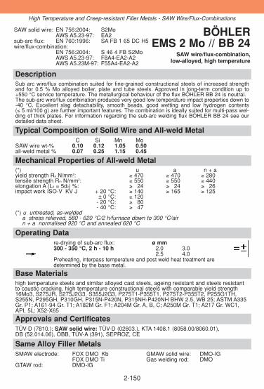
DescriptionSub arc wire/flux combination suited for fine-grained constructional steels of increased strengthand for 0.5 % Mo alloyed boiler, plate and tube steels. Approved in long-term condition up to+550 °C service temperature. The metallurgical behaviour of the flux BÖHLER BB 24 is neutral. The sub-arc wire/flux combination produces very good low temperature impact properties down to-40 °C. Excellent slag detachability, smooth beads, good wetting and low hydrogen contents(≤ 5 ml/100 g) are further important features. The combination is ideally suited for multi-pass wel-ding of thick plates. For information regarding the sub-arc welding flux BÖHLER BB 24 see ourdetailed data sheet.
Approvals and CertificatesTÜV-D (7810.); SAW solid wire: TÜV-D (02603.), KTA 1408.1 (8058.00/8060.01), DB (52.014.06), ÖBB, TÜV-A (391), SEPROZ, CE
Same Alloy Filler MetalsSMAW electrode: FOX DMO Kb GMAW solid wire: DMO-IG
FOX DMO Ti Gas welding rod: DMOGTAW rod: DMO-IG
Base Materialshigh temperature steels and similar alloyed cast steels, ageing resistant and steels resistantto caustic cracking, high temperature constructional steels with comparable yield strength16Mo3, S275JR, S275J2G3, S355J2G3, P275T1-P355T1, P275T2-P355T2, P255G1TH,S255N, P295GH, P310GH, P315N-P420N, P315NH-P420NH BHW 2.5, WB 25; ASTM A335Gr. P1; A161-94 Gr. T1; A182M Gr. F1; A204M Gr. A, B, C; A250M Gr. T1; A217 Gr. WC1,API, 5L: X52-X65
Operating Datare-drying of sub-arc flux: ø mm300 - 350 °C, 2 h - 10 h 2.0 3.0
2.5 4.0Preheating, interpass temperature and post weld heat treatment are determined by the base metal.
Mechanical Properties of All-weld Metal(*) u a n + ayield strength Re N/mm2: ≥ 470 ≥ 470 ≥ 280tensile strength Rm N/mm2: ≥ 550 ≥ 550 ≥ 440elongation A (L0 = 5d0) %: ≥ 324 ≥ 324 ≥ 326impact work ISO-V KV J + 20 °C: ≥ 140 ≥ 165 ≥ 125
± 0 °C: ≥ 120- 20 °C: ≥ 380- 40 °C: ≥ 347
(*) u untreated, as-weldeda stress relieved, 580 - 620 °C/2 h/furnace down to 300 °C/airn + a normalised 920 °C and annealed 620 °C
Typical Composition of Solid Wire and All-weld MetalC Si Mn Mo
SAW wire wt-% 0.10 0.12 1.05 0.50all-weld metal % 0.07 0.25 1.15 0.45
SAW solid wire: EN 756:2004: S2MoAWS A5.23-97: EA2
sub-arc flux: EN 760:1996: SA FB 1 65 DC H5wire/flux-combination:
EN 756:2004: S 46 4 FB S2MoAWS A5.23-97: F8A4-EA2-A2AWS A5.23M-97: F55A4-EA2-A2
BÖHLEREMS 2 Mo // BB 24
SAW wire/flux-combination,low-alloyed, high temperature
2-150
High Temperature and Creep-resistant Filler Metals - SAW Wire/Flux-Combinations

DescriptionThe sub-arc wire/flux combination is suited for fine-grained constructional steels of increasedstrength and for 0.5 % Mo alloyed boiler, plate and tube steels. Approved in long-term conditi-on up to +550 °C service temperature. The flux is active and shows some pick-up of silicon andmanganese. The sub-arc wire/flux combination produces higher strength values with very goodlow temperature impact properties down to -20 °C. For information regarding the sub-arcwelding flux BÖHLER BB 25 see our detailed data sheet.
Approvals and CertificatesTÜV-D (5678.), TÜV-A (618); SAW solid wire: TÜV-D (02603.), KTA 1408.1(8058.00/8060.01), DB (52.014.06), ÖBB, TÜV-A (391), SEPROZ, CE
Same Alloy Filler MetalsSMAW electrode: FOX DMO Kb Gas welding rod: DMO
FOX DMO Ti GTAW rod: DMO-IGGMAW solid wire: DMO-IG
Base Materialshigh temperature steels and similar alloyed cast steels, ageing resistant and steels resistantto caustic cracking, high temperature constructional steels with comparable yield strength16Mo3, S275JR, S275J2G3, S355J2G3, P275T1-P355T1, P275T2-P355T2, P255G1TH,S255N, P295GH, P310GH, P315N-P420N, P315NH-P420NH BHW 2.5, WB 25ASTM A335 Gr. P1; A161-94 Gr. T1; A182M Gr. F1; A204M Gr. A, B, C; A250M Gr. T1; A217Gr. WC1
Operating Datare-drying of sub-arc flux: ø mm300 - 350 °C, 2 h - 10 h 2.0
2.53.04.0
Preheating, interpass temperature and post weld heat treatment are determined by the base metal.
Mechanical Properties of All-weld Metal(*) uyield strength Re N/mm2: 500 (≥ 460)tensile strength Rm N/mm2: 600 (≥ 530) elongation A (L0 = 5d0) %: 30impact work ISO-V KV J + 20 °C: 120
± 0 °C: 100- 20 °C: 70- 40 °C: 40
(*) u untreated, as-welded
Typical Composition of Solid Wire and All-weld MetalC Si Mn Mo
SAW wire wt-% 0.10 0.12 1.05 0.5all-weld metal % 0.07 0.40 1.5 0.5
SAW solid wire: EN 756:2004: S2MoAWS A5.23-97: EA2
sub-arc flux: EN 760:1996: SA FB 1 68 DC H5wire/flux-combination:
EN 756:2004: S 46 3 FB S2MoAWS A5.23-97: F8A4-EA2-A2AWS A5.23M-97: F55A4-EA2-A2
BÖHLER EMS 2 Mo // BB 25
SAW wire/flux-combination,low-alloyed, high temperature
2-151
High Temperature and Creep-resistant Filler Metals - SAW Wire/Flux-Combinations

DescriptionSub arc wire / flux combination suited for 1 % Cr 0.5 % Mo alloyed boiler, plate and tube steels.Approved in long-term condition up to +570 °C service temperature. Bruscato ≤ 15 ppm. Themetallurgical behaviour of the flux BÖHLER BB 24 is neutral. The sub-arc wire/flux combinationproduces smooth beads, good wetting, excellent slag detachability, and low hydrogen contents (≤ 5 ml/100 g). are further important features. The combination is ideally suited for multi-pass welding of thick plates. For information regarding the sub-arc welding flux BÖHLER BB 24 see ourdetailed data sheet. For step cooling applications use flux BB 24 SC.
Approvals and CertificatesTÜV-D (7809.)SAW solid wire: TÜV-D (02605.), TÜV-A (393), SEPROZ, CE
Same Alloy Filler MetalsSMAW electrode: FOX DCMS Kb GMAW solid wire: DCMS-IG
FOX DCMS Ti Gas welding rod: DCMSGTAW rod: DCMS-IG SAW comb.: EMS 2CrMo/BB25
EMS 2CrMo/BB24 SC
Base Materialshigh temperature steels and similar alloyed cast steels, case hardening and nitriding steels ofsimilar chemical composition, similar alloyed heat treatable steels with tensile strength up to780 N/mm2, steels resistant to caustic cracking1.7335 13CrMo4-5, 1.7205 15CrMo5, 1.7225 42CrMo4, 1.7728 16CrMoV4, 1.7218 25CrMo4,1.7258 24CrMo5, 1.7354 G22CrMo5-4, 1.7357 G17CrMo5-5ASTM A193 Gr. B7; A335 Gr. P11 a. P12; A217 Gr. WC6
Operating Datare-drying of sub-arc flux: ø mm300 - 350 °C, 2 h - 10 h 2.5
3.04.0
Preheating, interpass temperature and post weld heat treatment are determined by the base metal.
Mechanical Properties of All-weld Metal(*) a n + ayield strength Re N/mm2: ≥ 460 ≥ 330tensile strength Rm N/mm2: ≥ 550 ≥ 480elongation A (L0 = 5d0) %: ≥ 22 330impact work ISO-V KV J + 20 °C: ≥ 47 120 (*) a annealed, 680 °C/2 h/furnace down to 300 °C/air
n + a normalised 920 °C and annealed 680 °C/2 h
Typical Composition of Solid Wire and All-weld MetalC Si Mn Cr Mo P As Sb Sn
SAW wire wt-% 0.12 0.10 0.8 1.2 0.50all-weld metal % 0.08 0.25 0.95 1.1 0.45 ≤ 0.012 ≤ 0.010 ≤ 0.005 ≤ 0.005
SAW solid wire: EN 12070:1999: S CrMo1AWS A5.23-97: EB2
sub-arc flux: EN 760:1996: SA FB 1 65 DC H5wire/flux-combination:
AWS A5.23-97: F8P4-EB2-B2AWS A5.23M-97: F55P4-EB2-B2
BÖHLER EMS 2 CrMo// BB 24
SAW wire/flux-combination,low-alloyed, high temperature
2-152
High Temperature and Creep-resistant Filler Metals - SAW Wire/Fux-Combinations

DescriptionThis welding consumable is suited for welding of creep resistant boiler plate, vessel and pipe con-struction. Approved in long-term condition up to +570 °C service temperature. Bruscato ≤ 15 ppm.The flux is active and shows some pick-up of silicon and manganese. For information regarding thesub-arc welding flux BÖHLER BB 25 see our detailed data sheet. For step cooling applications useflux BB 24 SC.
Approvals and CertificatesTÜV-D (5677.), TÜV-A (620), ABS (X)SAW solid wire: TÜV-D (02605.), TÜV-A (393), SEPROZ, CE
Same Alloy Filler MetalsSMAW electrode: FOX DCMS Kb GMAW solid wire: DCMS-IG
FOX DCMS Ti Gas welding rod: DCMSGTAW rod: DCMS-IG SAW comb.: EMS 2CrMo/BB24
EMS 2CrMo/BB24 SC
Base Materialshigh temperature steels and similar alloyed cast steels, case hardening and nitriding steels of similar chemical composition, similar alloyed heat treatable steels with tensile strength up to 780 N/mm2, steels resistant to caustic cracking
1.7335 13CrMo4-5, 1.7205 15CrMo5, 1.7225 42CrMo4, 1.7728 16CrMoV4, 1.7218 25CrMo4,1.7258 24CrMo5, 1.7354 G22CrMo5-4, 1.7357 G17CrMo5-5,
ASTM A193 Gr. B7; A335 Gr. P11 a. P12; A217 Gr. WC6
Operating Datare-drying of sub-arc flux: ø mm300 - 350 °C, 2 h - 10 h 2.5
3.04.0
Preheating, interpass temperature and post weld heat treatment are determined by the basemetal.
Mechanical Properties of All-weld Metal(*) ayield strength Re N/mm2: 580tensile strength Rm N/mm2: 630elongation A (L0 = 5d0) %: 24impact work ISO-V KV J + 20 °C: 120
- 20 °C: 50(*) a annealed, 620 °C/1 h/furnace down to 300 °C/air
Typical Composition of Solid Wire and All-weld MetalC Si Mn Cr Mo P As Sb Sn
SAW wire wt-% 0.12 0.10 0.8 1.2 0.5all-weld metal % 0.07 0.40 1.35 1.25 0.5 ≤ 0.012 ≤ 0.010 ≤ 0.005 ≤ 0.005
SAW solid wire:EN 12070:1999: S CrMo1AWS A5.23-97: EB2
sub-arc flux: EN 760:1996: SA FB 1 68 DC H5wire/flux-combination:
AWS A5.23-97: F8P4-EB2-B2AWS A5.23M-97: F55P4-EB2-B2
BÖHLER EMS 2 CrMo // BB 25
SAW wire/flux-combination,low alloyed, creep resistant
2-153
High Temperature and Creep-resistant Filler Metals - SAW Wire/Flux-Combinations

DescriptionSub-arc wire/flux combination suited for 2.25 % Cr 1 % Mo alloyed boiler, plate and tube steelsand also particularly for cracking plants in the crude oil industry. Approved in long-termcondition up to +600 °C service temperature. Bruscato ≤15 ppm. The deposit is noted for itsexcellent mechanical properties. Easy slag detachability and smooth bead surface are additio-nal quality features of this combination. For information regarding the sub-arc welding fluxBÖHLER BB 24 see our detailed data sheet. *For step-cooling applications we can offer a special product program.
Approvals and CertificatesTÜV-D (7812.)SAW solid wire: TÜV-D (02605.), KTA 1408.1 (8060.01), TÜV-A (393), SEPROZ, CE
Same Alloy Filler MetalsSMAW electrode: FOX CM 2 Kb GTAW rod: CM 2-IG
FOX CM 2 Kb SC* GMAW solid wire: CM 2-IGSAW comb.: CM 2 SC UP/BB 24 SC*
* For step-cooling application
Base Materialshigh temperature steels and similar alloyed cast steels, QT-steels similar alloyed up to 980 N/mm2 tensile strength, similar alloyed case hardening steels, nitriding steels
1.7380 10CrMo9-10, 1.8075 10CrSiMoV7, 1.7379 G17CrMo9-10
ASTM A335 Gr. P22; A217 Gr. WC 9
Operating Datare-drying of sub-arc flux: ø mm300 - 350 °C, 2 h - 10 h 2.5
3.04.0
Preheating, interpass temperature and post weld heat treatment are determined by the basemetal.
Mechanical Properties of All-weld Metal(*) ayield strength Re N/mm2: ≥ 460tensile strength Rm N/mm2: ≥ 530elongation A (L0 = 5d0) %: ≥ 322impact work ISO-V KV J + 20 °C: ≥ 47(*) a annealed, 670 - 720 °C/2 h/furnace down to 300 °C/air
Typical Composition of Solid Wire and All-weld MetalC Si Mn Cr Mo P As Sb Sn
SAW wire wt-% 0.12 0.10 0.6 2.6 0.95all-weld metal % 0.08 0.25 0.75 2.4 0.95 ≤ 0.010≤ 0.015 ≤ 0.005 ≤ 0.01
SAW solid wire: EN 12070:1999: S CrMo2AWS A5.23-97: EB3
sub-arc flux: EN 760:1996: SA FB 1 65 DC H5wire/flux-combination:
AWS A5.23-97: F9P2-EB3-B3AWS A5.23M-97: F55P0-EB3-B3
BÖHLER CM 2-UP // BB 24
SAW wire/flux-combination,low-alloyed, high temperature
2-154
High Temperature and Creep-resistant Filler Metals - SAW Wire/Flux-Combinations
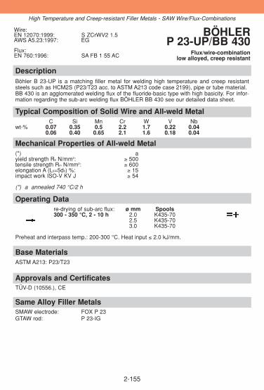
2-155
DescriptionBöhler B 23-UP is a matching filler metal for welding high temperature and creep resistantsteels such as HCM2S (P23/T23 acc. to ASTM A213 code case 2199), pipe or tube material. BB 430 is an agglomerated welding flux of the fluoride-basic type with high basicity. For infor-mation regarding the sub-arc welding flux BÖHLER BB 430 see our detailed data sheet.
Approvals and CertificatesTÜV-D (10556.), CE
Same Alloy Filler MetalsSMAW electrode: FOX P 23GTAW rod: P 23-IG
Base MaterialsASTM A213: P23/T23
Operating Datare-drying of sub-arc flux: ø mm Spools300 - 350 °C, 2 - 10 h 2.0 K435-70
2.5 K435-703.0 K435-70
Preheat and interpass temp.: 200-300 °C. Heat input ≤ 2.0 kJ/mm.
Mechanical Properties of All-weld Metal(*) ayield strength Re N/mm2: ≥ 500tensile strength Rm N/mm2: ≥ 600elongation A (L0=5d0) %: ≥ 15impact work ISO-V KV J ≥ 54
(*) a annealed 740 °C/2 h
Typical Composition of Solid Wire and All-weld MetalC Si Mn Cr W V Nb
wt-% 0.07 0.35 0.5 2.2 1.7 0.22 0.040.06 0.40 0.65 2.1 1.6 0.18 0.04
Wire:EN 12070:1999: S ZCrWV2 1.5AWS A5.23:1997: EG
Flux:EN 760:1996: SA FB 1 55 AC
BÖHLER P 23-UP/BB 430
Flux/wire-combinationlow alloyed, creep resistant
High Temperature and Creep-resistant Filler Metals - SAW Wire/Flux-Combinations

2-156
DescriptionBöhler P 24-UP is a matching filler metal for welding high temperature and creep resistantsteels such as 7CrMoVTiB (P24/T24 acc. to ASTM A213). The chemistry of the wire will be opti-mized with respect to the creep rupture properties. Böhler B 430 is an agglomerated weldingflux of the fluoride-basic type with high basicity. For information regarding the sub-arc weldingflux BÖHLER BB 430 see our detailed data sheet.
Approvals and CertificatesTÜV-D (10456.), CE
Same Alloy Filler MetalsSMAW electrode: FOX P 24GTAW rod: P 24-IG
Base Materials7CrMoVTiB10-10, P24 acc. to ASTM A 213 Draft
Operating DataRedrying: ø mm Spools300-350 °C, 2-10 h 2.0 K435-70
2.5 K435-703.0 K435-70
Preheating and interpass temp.: 200-300 °C. Heat input ≤ 2.0 kJ/mm.
Mechanical Properties of All-weld Metal(*) ayield strength Re N/mm2: ≥ 450tensile strength Rm N/mm2: ≥ 590elongation A (L0=5d0) %: ≥ 15impact work ISO-V KV J ≥ 54
(*) a annealed 740°C/ 2 h
Typical Composition of Solid Wire and All-weld MetalC Si Mn Cr Mo V Nb
wt-% 0.10 0.25 0.55 2.5 1.0 0.24 0.050.08 0.30 0.75 2.4 0.95 0.20 0.04
Wire:EN 12070:1999: S ZCrMo2VNbAWS A5.23:1997 EG
Flux:EN 760:1996: SA FB 1 55 AC
BÖHLER P 24-UP/BB 430
Flux/wire-combinationlow alloyed, creep resistant
High Temperature and Creep-resistant Filler Metals - SAW Wire/Flux-Combinations

DescriptionSub arc wire /flux combination suited for 5 % Cr 0.5 % Mo alloyed steels, particularly for hothydrogen service. High temperature strength at service temperatures up to +600 °C. The weld deposit exhibits good mechanical properties. Easy slag detachability and smoothbead surface are additional quality features. For information regarding the sub-arc welding flux BÖHLER BB 24 see our detailed data sheet.
Approvals and CertificatesSAW solid wire: TÜV-D (02605.), TÜV-A (393), SEPROZ, CE
Base Materialssimilar alloyed high temperature steels and cast steels
1.7362 X12CrMo5, 1.7363 GX12CrMo5
ASTM A213 Gr. T5; A217 Gr. C5; A335 Gr. P5
Operating Datare-drying of sub-arc flux: ø mm300 - 350 °C, 2 h - 10 h 4.0
Preheating and interpass temperature and post weld heat treatment are determined by thebase metal.
Mechanical Properties of All-weld Metal(*) ayield strength Re N/mm2: ≥ 450tensile strength Rm N/mm2: ≥ 590elongation A (L0 = 5d0) %: ≥ 318impact work ISO-V KV J + 20 °C: ≥ 347(*) a annealed 740 °C/4 h/furnace down to 300 °C/air
Typical Composition of Solid Wire and All-weld MetalC Si Mn Cr Mo
SAW wire wt-% 0.08 0.3 0.50 5.8 0.60all-weld metal % 0.06 0.4 0.75 5.5 0.55
SAW solid wire: EN 12070:1999: S CrMo5AWS A5.23-97: EB6
sub-arc flux: EN 760:1996: SA FB 1 65 DC H5wire/flux-combination:
AWS A5.23-97: F9PZ-EB6-B6AWS A5.23M-97: F62PZ-EB6-B6
BÖHLER CM 5-UP // BB 24
SAW wire/flux-combination,high-alloyed, high temperature
2-157
Same Alloy Filler MetalsSMAW electrode: FOX CM 5 KbGTAW rod: CM 5-IGGMAW solid wire: CM 5-IG
High Temperature and Creep-resistant Filler Metals - SAW Wire/Flux-Combinations

DescriptionSub-arc wire/flux combination suited for creep resistant 9 % Cr steels, especially for P91 acc.ASTM A335. Approved in long-term condition up to +650 °C service temperature. The wire andflux are precisely balanced to consistently meet the highest technical requirements. Forinformation regarding the sub-arc welding flux BÖHLER BB 910 see our detailed data sheet.
Approvals and CertificatesTÜV-D (09229.), SEPROZ, CE
Same Alloy Filler MetalsSMAW electrode: FOX C 9 MV GMAW solid wire: C 9 MV–IGGTAW rod: C 9 MV-IG GMAW metal cored wire: C 9 MV-MC
Base Materialssimilar alloyed creep resistant steels
1.4903 X10CrMoVNb9-1
ASTM A199 Gr. T91; A335 Gr. P91; A213/213M Gr. T91
Operating Datare-drying of sub-arc flux: ø mm300 - 350 °C, 2 h - 10 h 2.5
3.0
Preheating and interpass temperature 200-300 °C. After welding the joint should cool downbelow 80 °C in order to finish the martensitic transformation. Pipe welds with wall thickness upto 45 mm can be cooled down to room temperature. For heavier wall thicknesses or stressedcomponents, unfavourable possible stress condition must be considered. The recommendedpost weld heat treatment is annealing after welding at 760 °C/min. 2 hrs, max. 10 hrs, heating/cooling-rates below 550 °C max. 150 °C/hr, above 550 °C max 80 °C/hr. For optimised toughness properties a technology which ensures thin welding layers isrecommended.
Mechanical Properties of All-weld Metal(*) ayield strength Re N/mm2: 610 (≥ 560)tensile strength Rm N/mm2: 740 (≥ 700)elongation A (L0 = 5d0) %: 20 (≥ 318)impact work ISO-V KV J (≥ 347)(*) a annealed, 760 °C/2 h/furnace down to 300 °C/air
Typical Composition of Solid Wire and All-weld MetalC Si Mn Cr Ni Mo V Nb
SAW wire wt-% 0.12 0.25 0.6 9.0 0.7 0.95 0.20 0.06all-weld metal % 0.11 0.30 0.7 8.9 0.6 0.9 0.20 0.05
SAW solid wire: EN 12070:1999: S CrMo91AWS A5.23-97: EB9
sub-arc flux: EN 760:1996: SA FB 2 55 DC H5wire/flux-combination:
AWS A5.23-97: F9PZ-EB9-B9AWS A5.23M-97: F62PZ-EB9-B9
BÖHLER C 9 MV-UP// BB 910
SAW wire/flux-combination,high-alloyed, creep resistant
2-158
High Temperature and Creep-resistant Filler Metals - SAW Wire/Flux-Combinations

DescriptionSub-arc wire/flux combination designed for 9 % Cr creep resistant steel, especially forP92/NF616. Approved in long-term condition up to +650 °C service temperature. For informa-tion regarding the sub-arc welding flux BÖHLER BB 910 see our detailed data sheet.
Approvals and CertificatesTÜV-D (09390.), CE
Same Alloy Filler MetalsSMAW electrode: FOX P 92 GTAW rod: P 92-IG
Base Materialssimilar alloyed creep resistant steels
NF 616
ASTM A335 Gr. P 92 (T92); A213/213M Gr. T92
Operating Datare-drying of sub-arc flux: ø mm300 - 350 °C / 2 h - 10 h 3.0
Preheating and interpass temperature 200-300 °C. After welding the joint should cool downbelow 80 °C in order to finish the martensite transformation. Pipe welds with wall thickness upto 45 mm can be cooled down to room temperature For heavier wall thicknesses or stressedcomponents, unfavourable possible stress condition must be considered. The recommendedpost weld heat treatment is annealing at 760 °C/min. 2 hrs, max. 10 hrs., heating/cooling ratesbelow 550 °C max. 150 °C/hr, above 550 °C max 80 °C/hr. For optimised toughness properties a technology which ensures thin welding layers isrecommended.
Mechanical Properties of All-weld Metal(*) ayield strength Re N/mm2: 660 (≥ 560)tensile strength Rm N/mm2: 780 (≥ 700)elongation A (L0 = 5d0) %: 320 (≥ 318)impact work ISO-V KV J 360 (≥ 347)(*) a annealed, 760 °C/4 h/furnace down to 300 °C/air
Typical Composition of Solid Wire and All-weld MetalC Si Mn Cr Mo Ni V W Nb
SAW wire wt-% 0.11 0.40 0.45 8.8 0.45 0.65 0.2 1.65 0.06all-weld metal % 0.10 0.40 0.6 8.7 0.45 0.6 0.2 1.65 0.05
SAW solid wire: EN 12070:1999: S ZCrMoWVNb9 0.5 1.5AWS A5.23-97: EB9 (mod.)
sub-arc flux: EN 760:1996: SA FB 2 55 DC H5BÖHLER
P 92-UP // BB 910SAW wire/flux-combination,
high-alloyed, creep resistant
2-159
High Temperature and Creep-resistant Filler Metals - SAW Wire/Flux-Combinations

DescriptionSuited for analogous and similar creep resistant steels in turbine and steam boiler constructionas well as in the chemical industry. Approved in long-term condition up to +650 °C servicetemperature. For information regarding the sub-arc welding flux BÖHLER BB 24 see our detai-led data sheet.
Approvals and CertificatesTÜV-D (07813.)SAW solid wire: TÜV-D (07813.), KTA 1408.1 (8060.01), TÜV-A (393), SEPROZ, CE
Same Alloy Filler MetalsSMAW electrode: FOX 20 MVWGTAW rod: 20 MVW-IG
Base Materialssimilar alloyed creep resistant steels
1.4935 X20CrMoWV12-1, 1.4922 X20CrMoV12-1, 1.4923 X22CrMoV12-11.4913 X19CrMoVNb11-1 (Turbotherm, 20 MVNb), 1.4931 GX22CrMoV12-1
Operating Datare-drying of sub-arc flux: ø mm300 - 350 °C, 2 h - 10 h 3.0
Preheating and interpass temperature 400-450 °C (austenitic welding) or 250-300 °C (marten-sitic welding). Root passes should principally be welded in the martensitic range. Lower preheatand interpass temperatures are possible, yet must be approved by practical welding tests andprocess qualification tests. After welding cooling to 90±10 °C, followed by tempering at 760 °C for three minutes / mm wallthickness at least for 2 hours. Tempering, if specified, at 1050 °C for 1/2 hour/oil and annealingat 760 °C for 2 hours. Further details on the welding technology available on request.
Mechanical Properties of All-weld Metal(*) ayield strength Re N/mm2: ≥ 550tensile strength Rm N/mm2: ≥ 660elongation A (L0 = 5d0) %: ≥ 315impact work ISO-V KV J ≥ 347(*) a annealed, 760 °C/4 h/furnace down to 300 °C/air
Typical Composition of Solid Wire and All-weld MetalC Si Mn Cr Mo Ni V W
SAW wire wt-% 0.25 0.25 0.8 11.5 0.9 0.6 0.3 0.5all-weld metal % 0.18 0.3 0.75 11.4 0.85 0.45 0.3 0.5
SAW solid wire:EN 12070:1999: S CrMoWV12
sub-arc flux:EN 760:1996: SA FB 2 65 DC H5
BÖHLER 20 MVW-UP // BB 24
SAW wire/flux-combination,high-alloyed, creep resistant
2-160
High Temperature and Creep-resistant Filler Metals - SAW Wire/Flux-Combinations

DescriptionSub-arc wire/flux combination for high quality joint weld on high temperature austenitic CrNi-steels at service temperature up to +700 °C (+300 °C in the case of wet corrosion). The con-trolled ferrite content (3-8 FN) ensures hot cracking resistance. The deposit is insusceptible tosigma phase embrittlement. For information regarding the sub-arc welding flux BÖHLER BB202 see our detailed data sheet. Steels to German material no. 1.4550 and 1.4551 which areapproved for the high temperature range up to +550 °C, can also be welded.
Approvals and CertificatesCE
Same Alloy/Similar Alloy Filler MetalsSMAW electrode: FOX E 308 H GMAW solid wire: CN 18/11-IG
FOX CN 18/11 GMAW flux-cored wire: E 308 H-FDGTAW rod: ER 308 H-IG E 308 H PW-FD
CN 18/11-IG
Base Materialssimilar alloyed creep resistant steels
1.4948 X6CrNi18-11, 1.4949 X3CrNiN18-11
AISI 304H, 321H, 347H
Operating Datare-drying of sub-arc flux: ø mm300 - 350 °C, 2 h - 10 h 3.0
Preheating is not required, only in case of wall thickness above 25 mm preheat up to 150 °C.The interpass temperature should not exceed 200 °C.
Mechanical Properties of All-weld Metal(*) uyield strength Re N/mm2: ≥ 320tensile strength Rm N/mm2: ≥ 550elongation A (L0 = 5d0) %: ≥ 335impact work ISO-V KV J + 20 °C: ≥ 380(*) u untreated, as-welded
Typical Composition of Solid Wire and All-weld MetalC Si Mn Cr Ni FN
SAW wire wt-% 0.05 0.4 1.6 18.8 9.3all-weld metal % 0.04 0.5 1.3 18.5 9.3 3-8
SAW solid wire:EN 12072:1999: S 19 9 HAWS A5.9-93: ER19-10H
sub-arc flux:EN 760:1996: SA FB 2 DC
BÖHLER CN 18/11-UP // BB 202
SAW wire/flux-combination,high-alloyed, creep resistant
2-161
High Temperature and Creep-resistant Filler Metals - SAW Wire/Flux-Combinations

DescriptionMo-alloyed gas welding rod recommended for mild steels and 0.5 % Mo alloyed steels. Highviscous weld puddle. Easy to operate. Approved in long-term condition up to +500 °C servicetemperature.
Approvals and CertificatesTÜV-D (0146.), DB (70.014.03), ÖBB, SEPROZ, CE
Same Alloy Filler MetalsSMAW electrode: FOX DMO Kb GMAW solid wire: DMO-IG
FOX DMO Ti SAW combination: EMS 2 Mo/BB 24GTAW rod: DMO-IG EMS 2 Mo/BB 25
Base Materialshigh temperature steels, same alloyed
16Mo3, P285NH, P295NH, P255G1TH, P295GH
ASTM A335 Gr. P1, A36 Gr. all; A283 Gr. B, C, D; A285 Gr. B; A414 Gr. C; A442 Gr. 60; A515 Gr. 60; A516 Gr. 55, 60; A570 Gr. 33, 36, 40
Operating Datarod marking: ø mm
front: O IV 2.0back: R60-G 2.5
3.24.0
Preheating and post weld heat treatment as required by the base metal.
Mechanical Properties of All-weld Metal(*) uyield strength Re N/mm2: 330 (≥ 295)tensile strength Rm N/mm2: 470 (≥ 440)elongation A (L0 = 5d0) %: 24 (≥ 322)impact work ISO-V KV J + 20 °C: 60 (≥ 339)(*) u untreated, as-welded
Typical Composition of Welding RodC Si Mn Mo
wt-% 0.12 0.15 1.0 0.5
EN 12536:2000: O IVAWS A5.2-92: R60-G W.Nr.: 1.5425
BÖHLER DMOGas welding rod, low-alloyed,
high temperature
2-162
High Temperature and Creep-resistant Filler Metals - Gas Welding Rod

DescriptionCrMo-alloyed gas welding rod for high temperature boiler and tube steels equivalent to13CrMo4-5 (1.25 % Cr 0.5 % Mo). Approved in long-term condition up to +500 °C service tempera-ture. High viscous weld puddle.
Approvals and CertificatesTÜV-D (1363.), SEPROZ, CE
Same Alloy Filler MetalsSMAW electrode: FOX DCMS Kb GMAW solid wire: DCMS-IG
FOX DCMS Ti SAW combination: EMS 2 CrMo/BB 24GTAW rod: DCMS-IG EMS 2 CrMo/BB 24 SC
EMS 2 CrMo/BB 25
Base Materialshigh temperature steels same alloyed, steels resistant to caustic cracking
1.7335 13CrMo4-5, 1.7205 15CrMo5, 1.7354 G22CrMo5-4, 1.7357 G17CrMo5-5, 16CrMoV4, ASTM A335 Gr. P 11 a. P 12; A193 Gr. B7; A217 Gr. WC6
Operating Datarod marking: ø mm
front: O V 2.5back: R65-G 3.0
Wall thicknesses over 6 mm should be preheated to 100-200 °C and tempered at 660-700 °Cfor at least 1/2 hours followed by cooling in still air.
Mechanical Properties of All-weld Metal(*) ayield strength Re N/mm2: ≥ 315tensile strength Rm N/mm2: ≥ 490elongation A (L0 = 5d0) %: ≥ 318impact work ISO-V KV J + 20 °C: ≥ 347(*) a annealed, 680 °C, 2 h/furnace down to 300 °C/air
Typical Composition of Welding RodC Si Mn Cr Mo
wt-% 0.12 0.1 0.8 1.2 0.5
EN 12536:2000: O VAWS A5.2-92: R65-G W.Nr.: 1.7346
BÖHLER DCMSGas welding rod, low-alloyed,
high temperature
2-163
High Temperature and Creep-resistant Filler Metals - Gas Welding Rod

2-164
Notes
2-165
Notes

2-166
Notes
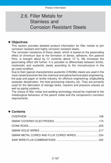
2-167
2.6. Filler Metals forStainless andCorrosion Resistant Steels
ObjectivesThis section provides detailed product information for filler metals to joincorrosion resistant and highly corrosion resistant steels.The corrosion resistance of these steels, which is based on the passivatingeffect of chromium due to the formation of dense, adhesive, thin passivefilms, is brought about by Cr contents above 12 %. Mo increases thepassivating effect still further. It is possible to differentiate between ferritic,martensitic and austenitic steels according to the microstructure in theas-used condition. Due to their special characteristics austenitic CrNi(Mo) steels are used in themost varied branches like the chemical and petrochemical plant engineering,the pulp and paper or textile industry, for offshore engineering, shipbuildingseawater desalination, the food processing industry, etc. They are primarilyused for the fabrication of storage tanks, reactors and pressure vessels aswell as piping systems. The choice of filler metal and welding technology should be matched to themetallurgical behaviour of the parent metal and the component’s corrosionrequirements.
Contents
OVERVIEW .............................................................................................168
SMAW COVERED ELECTRODES ..........................................................174
GTAW RODS............................................................................................205
GMAW SOLID WIRES .............................................................................217
GMAW METAL CORED AND FLUX CORED WIRES..............................234
SAW WIRE/FLUX-COMBINATIONS .......................................................252
◆
◆
Product Information

2-168
Overview – Standard Classifications
Böhler EN / ENISO AWSSMAW covered electrodesFOX CN 13/4 1600: E 13 4 B 6 2 A5.4-92: E410NiMo-25FOX CN 13/4 SUPRA 1600: E 13 4 B 4 2 A5.4-92: E410NiMo-15FOX KW 10 1600: E 13 B 2 2 A5.4-92: E410-15(mod.)FOX SKWA 1600: E 17 B 2 2 A5.4-92: E430-15FOX SKWAM 1600: E Z 17 Mo B 2 2 –FOX CN 16/6 M-HD 1600: E Z 16 6 Mo B 6 2 H5 –FOX CN 17/4 PH 1600: E Z 17 4 Cu B 4 3 H5 A5.4-92: E630-15(mod.)FOX EAS 2 1600: E 19 9 L B 2 2 A5.4-92: E308L-15FOX EAS 2-A 1600: E 19 9 L R 3 2 A5.4-92: E308L-17FOX EAS 2-VD 1600: E 19 9 L R 1 5 A5.4-92: E308L-17FOX SAS 2 1600: E 19 9 Nb B 2 2 A5.4-92: E347-15FOX SAS 2-A 1600: E 19 9 Nb R 3 2 A5.4-92: E347-17FOX EAS 4 M 1600: E 19 12 3 LB 2 2 A5.4-92: E316L-15FOX EAS 4 M-A 1600: E 19 12 3 L R 3 2 A5.4-92: E316L-17FOX EAS 4 M (LF) 1600: E Z19 12 3 LB 2 2 A5.4-92: E316L-15FOX EAS 4 M-VD 1600: E 19 12 3 L R 1 5 A5.4-92: E316L-17FOX EAS 4 M-TS 1600: E 19 12 3 L R 1 2 A5.4-92: E316L-16(mod.)FOX SAS 4 1600: E 19 12 3 Nb B 2 2 A5.4-92: E318-15FOX SAS 4-A 1600: E 19 12 3 Nb R 3 2 A5.4-92: E318-17FOX EAS 2 Si 1600: E Z 19 14 Si B 2 2 –FOX E317 L – A5.4-92: E317L-17FOX ASN 5 1600: E 18 16 5 N L B 2 2 A5.4-92: E317LN-15(mod.)FOX ASN 5-A 1600: E 18 16 5 N L R 3 2 A5.4-92: E317LN-17(mod.)FOX AM 400 1600: E Z 22 18 4 L B 2 2 –FOX EASN 25 M 1600: EZ 25 22 2 NL B 2 2 –FOX CN 20/25 M 1600: E 20 25 5 Cu N L B 2 2 A5.4-92: E385-15(mod.)FOX CN 20/25 M-A 1600: E 20 25 5 Cu N L R 3 2 A5.4-92: E385-17(mod.)FOX CN 22/9 N-B 1600: E 22 9 3 L B 2 2 A5.4-92: E2209-15FOX CN 22/9 N 1600: E 22 9 3 L R 3 2 A5.4-92: E2209-17FOX CN 25/9CuT 1600: E 25 9 4 N L B 2 2 A5.9-93: E2553-15(mod.)
GTAW rodsCN 13/4-IG 12072: W 13 4 A5.9-93: ER410 NiMo(mod.)EAS 2-IG 12072: W 19 9 L A5.9-93: ER308LSAS 2-IG 12072: W 19 9 Nb A5.9-93: ER347EAS 4 M-IG 12072: W 19 12 3 L A5.9-93: ER316LSAS 4-IG 12072: W 19 12 3 Nb A5.9-93: ER318EASN 2 Si-IG 12072: W Z 19 13 Si NL –ASN 5-IG 12072: W Z 18 16 5 NL A5.9-93: ER317LN(mod.)AM 400-IG 12072: W Z 22 17 8 4 NL –EASN 25 M-IG 12072: W 25 22 2 NL –CN 20/25 M-IG 12072: W Z 20 25 5 Cu NL A5.9-93: ER385(mod.) CN 22/9 N-IG 12072: W 22 9 3 NL A5.9-93: ER2209CN 25/9 CuT-IG 12072: W 25 9 4 NL A5.9-93: ER2553(mod.)
◆
Corrosion Resistant Filler Metals

2-169
Overview – Typical Chemical Composition
Böhler C Si Mn Cr Ni Mo Nb Ti N Cu TSMAW covered electrodesFOX CN 13/4 0.035 0.3 0.5 12.2 4.5 0.5FOX CN 13/4 SUPRA 0.03 0.3 0.6 12.2 4.5 0.5FOX KW 10 0.08 0.7 0.8 13.5FOX SKWA 0.08 0.4 0.3 17.0FOX SKWAM 0.22 0.3 0.4 17.0 1.3FOX CN 16/6 M-HD 0.03 0.3 0.6 15.5 5.8 1.2FOX CN 17/4 PH 0.03 0.3 0.6 16.0 4.9 0.4 0.2 3.2FOX EAS 2 0.03 0.4 1.3 19.5 10.5FOX EAS 2-A 0.03 0.8 0.8 19.8 10.2FOX EAS 2-VD 0.02 0.7 0.7 19.8 10.5FOX SAS 2 0.03 0.4 1.3 19.8 10.2 +FOX SAS 2-A 0.03 0.8 0.8 19.5 10.0 +FOX EAS 4 M 0.03 0.4 1.2 18.8 11.8 2.7FOX EAS 4 M-A 0.03 0.8 0.8 18.8 11.5 2.7FOX EAS 4 M (LF) 0.03 0.4 1.2 18.5 12.8 2.4FOX EAS 4 M-VD 0.03 0.7 0.7 19.0 12.0 2.7FOX EAS 4 M-TS 0.03 0.7 0.8 19.4 11.8 2.7FOX SAS 4 0.03 0.4 1.3 18.8 11.8 2.7 +FOX SAS 4-A 0.03 0.8 0.8 19.0 12.0 2.7 +FOX EAS 2 Si <0.02 4.4 1.1 19.0 15.2FOX E317L 0.03 0.8 0.9 19.0 13.0 3.6 +FOX ASN 5 ≤0.04 0.5 2.5 18.5 17.0 4.3 0.17FOX ASN 5-A ≤0.035 0.7 1.2 18.0 17.0 4.5 0.13FOX AM 400 ≤0.04 0.8 7.5 21.8 18.3 3.7 0.20FOX EASN 25 M ≤0.035 0.4 5.3 25.0 22.0 2.2 0.14FOX CN 20/25 M ≤0.04 0.4 3.8 20.0 25.0 6.3 0.14 1.4FOX CN 20/25 M-A 0.03 0.7 1.7 20.3 25.0 6.2 0.17 1.5FOX CN 22/9 N-B 0.03 0.3 1.1 22.6 8.8 3.1 0.16FOX CN 22/9 N 0.03 0.8 0.9 22.6 9.0 3.1 0.17FOX CN 25/9CuT 0.03 0.5 1.0 25.0 9.5 3.7 0.22 0.7 0.7
GTAW rodsCN 13/4-IG 0.01 0.7 0.7 12.3 4.7 0.5EAS 2-IG ≤0.02 0.45 1.8 20.0 10.0SAS 2-IG 0.05 0.5 1.8 19.6 9.5 +EAS 4 M-IG ≤0.02 0.5 1.8 18.5 12.3 2.8SAS 4-IG 0.035 0.45 1.7 19.5 11.4 2.7 +EASN 2 Si-IG ≤0.012 4.6 0.7 19.5 13.4 0.12ASN 5-IG ≤0.02 0.4 5.5 19.0 17.2 4.3 0.16AM 400-IG 0.03 0.65 7.5 22.2 18.0 3.7 0.24EASN 25 M-IG 0.014 0.1 6.0 25.0 22.5 2.2 0.12CN 20/25 M-IG ≤0.02 0.7 4.7 20.0 25.4 6.2 0.12 1.5CN 22/9 N-IG 0.02 0.4 1.7 22.5 8.8 3.2 0.15CN 25/9 CuT-IG 0.02 0.3 0.7 25.2 9.2 3.6 0.22 0.6 0.62
◆
Corrosion Resistant Filler Metals

2-170
Overview – Standard Classifications (continued)
Böhler EN AWSGMAW solid wiresKW 5 Nb-IG 12072: G Z 13 Nb L A5.9-93: ER409 CbCAT 430 L Cb-IG 12072: G Z 18 Nb L A5.9-93: ER430(mod.)CAT 439 L Ti-IG 12072: G Z 18 Ti L A5.9-93: ER430(mod.)CN 13/4-IG 12072: G 13 4 A5.9-93: ER410NiMo (mod.)KW 10-IG 12072: G Z 13 A5.9-93: ER410(mod.)KWA-IG 12072: G 17 A5.9-93: ER430(mod.)SKWA-IG 12072: G Z 17 Ti A5.9-93: ER430(mod.)SKWAM-IG 12072: G Z 17 Mo –EAS 2-IG (Si) 12072: G 19 9 L Si A5.9-93: ER308LSiSAS 2-IG (Si) 12072: G 19 9 Nb Si A5.9-93: ER347SiEAS 4 M-IG (Si) 12072: G 19 12 3 L Si A5.9-93: ER316LSiSAS 4-IG (Si) 12072: G 19 12 3 Nb Si A5.9-93: ER318(mod.) ASN 5-IG (Si) 12072: G Z 18 16 5 NL A5.9-93: ER317LN(mod.) AM 400-IG 12072: G Z 22 17 8 4 NL –CN 20/25 M-IG (Si) 12072: G Z 20 25 5 Cu NL A5.9-93: ER385(mod.)CN 22/9 N-IG 12072: G 22 9 3 NL A5.9-93: ER2209CN 25/9 CuT-IG 12072: G 25 9 4 NL A5.9-93: ER2553(mod.)
GMAW metal cored and flux cored wiresCN 13/4-MC 17633-A: T 13 4 MM 2 A5.22-95: EC410NiMo(mod.)CN 13/4-MC (F) 17633-A: T 13 4 MM 2 A5.9-93: EC410NiMo(mod.)EAS 2-MC 17633-A: T 19 9 L MM 1 A5.9-93: EC308L(mod.)EAS 4M-MC 17633-A: T 19 12 3 L MM 1 A5.22-95: EC316L(mod.)EAS 2-FD 17633-A: T 19 9 L R M 3 A5.22-95: E308LT0-4
T 19 9 L R C 3 E308LT0-1EAS 2 PW-FD 17633-A: T 19 9 L P M 1 A5.22-95: E308LT1-4
T 19 9 L P C 1 E308LT1-1EAS 2 PW-FD (LF) 17633-A: T 19 9 L P M 1 A5.22-95: E308LT1-4
T 19 9 L P C 1 E308LT1-1SAS 2-FD 17633-A: T 19 9 Nb R M 3 A5.22-95: E347T0-4
T 19 9 Nb R C 3 E347T0-1SAS 2 PW-FD 17633-A: T 19 9 Nb P M 1 A5.22-95: E347T1-4
T 19 9 Nb P C 1 E347T1-1EAS 4 M-FD 17633-A: T 19 12 3 L R M 3 A5.22-95: E316LT0-4
T 19 12 3 L R C 3 E316LT0-1EAS 4 PW-FD 17633-A: T 19 12 3 L P M 1 A5.22-95: E316LT1-4
T 19 12 3 L P C 1 E316LT1-1EAS 4 PW-FD (LF) 17633-A: T 19 12 3 L P M 1 A5.22-95: E316LT1-4
T 19 12 3 L P C 1 E316LT1-1SAS 4-FD 17633-A: T 19 12 3 Nb R M 3
T 19 12 3 Nb R C 3SAS 4 PW-FD 17633-A: T 19 12 3 Nb R M 1
T 19 12 3 Nb R C 1E 317L-FD 17633-A: TZ 19 13 4 L R M 3 A5.22-95: E317LT0-4
TZ 19 13 4 L R C 3 A5.22-95: E317LT0-1E 317L PW-FD 17633-A: TZ 19 13 4 L P M 1 A5.22-95: E317LT1-4
TZ 19 13 4 L P C 1 A5.22-95: E317LT1-1CN 22/9 N-FD 17633-A: T 22 9 3 LN R M 3 A5.22-95: E2209T0-4
T 22 9 3 LN R C 3 E2209T0-1CN 22/9 PW-FD 17633-A: T 22 9 3 LN P M 1 A5.22-95: E2209T1-4
T 22 9 3 LN P C 1 E2209T1-1
◆
Corrosion Resistant Filler Metals
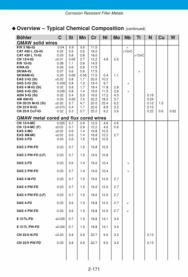
2-171
◆
Corrosion Resistant Filler Metals
Overview – Typical Chemical Composition (continued)
Böhler C Si Mn Cr Ni Mo Nb Ti N Cu WGMAW solid wiresKW 5 Nb-IG 0.04 0.6 0.6 11.5 +CAT 430 L Cb-IG 0.02 0.5 0.5 18.0 >12xCCAT 439 L Ti-IG 0.03 0.8 0.8 18.0 >12xCCN 13/4-IG ≤0.01 0.65 0.7 12.2 4.8 0.5KW 10-IG 0.08 1.1 0.6 14.5KWA-IG 0.06 0.6 0.6 17.5SKWA-IG 0.07 0.6 0.6 17.5 +SKWAM-IG 0.20 0.65 0.55 17.0 0.4 1.1EAS 2-IG (Si) ≤0.02 0.8 1.7 20.0 10.2SAS 2-IG (Si) 0.035 0.8 1.3 19.4 9.7 +EAS 4 M-IG (Si) 0.02 0.8 1.7 18.4 11.8 2.8SAS 4-IG (Si) 0.035 0.8 1.4 19.0 11.5 2.8 +ASN 5-IG (Si) 0.02 0.4 5.5 19.0 17.2 4.3 0.16AM 400-IG 0.03 0.65 7.5 22.2 18.0 3.7 0.24CN 20/25 M-IG (Si) ≤0.02 0.7 4.7 20.0 25.4 6.2 0.12 1.5CN 22/9 N-IG ≤0.015 0.4 1.7 22.6 8.8 3.2 0.15CN 25/9 CuT-IG 0.02 0.3 0.7 25.2 9.2 3.6 0.22 0.6 0.62
GMAW metal cored and flux cored wiresCN 13/4-MC 0.025 0.7 0.9 12.0 4.6 0.6CN 13/4-MC (F) ≤0.03 0.7 0.9 12.2 4.6 0.6EAS 2-MC ≤0.03 0.6 1.4 19.8 10.5EAS 4M-MC ≤0.03 0.6 1.4 18.8 12.2 2.7EAS 2-FD 0.03 0.6 1.5 19.8 10.5
EAS 2 PW-FD 0.03 0.7 1.5 19.8 10.5
EAS 2 PW-FD (LF) 0.03 0.7 1.5 19.5 10.8
SAS 2-FD 0.03 0.6 1.4 19.0 10.4 +
SAS 2 PW-FD 0.03 0.7 1.4 19.0 10.4 +
EAS 4 M-FD 0.03 0.7 1.5 19.0 12.0 2.7
EAS 4 PW-FD 0.03 0.7 1.5 19.0 12.0 2.7
EAS 4 PW-FD (LF) 0.03 0.7 1.5 18.0 12.5 2.7
SAS 4-FD 0.03 0.6 1.3 18.8 12.2 2.7 +
SAS 4 PW-FD 0.03 0.6 1.3 18.8 12.2 2.7 +
E 317L-FD ≤0.035 0.7 1.3 18.8 13.1 3.4
E 317L PW-FD ≤0.035 0.7 1.3 18.8 13.1 3.4
CN 22/9 N-FD ≤0.03 0.8 0.9 22.7 9.0 3.2 0.13
CN 22/9 PW-FD 0.03 0.8 0.9 22.7 9.0 3.2 0.13
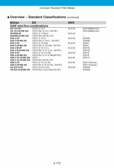
2-172
Overview – Standard Classifications (continued)
Böhler EN AWSSAW wire/flux-combinationsCN 13/4-UP 12072: S 13 4 A5.9-93: ER410NiMo(mod.)CN 13/4-UP/BB 203 12072/760: S 13 4 / SA FB 2 ER410NiMo(mod.)SKWAM-UP 12072: S 17 Mo H A5.9-93: –SKWAM-UP/BB 203 12072/760: SA FB 2 DC –EAS 2-UP 12072: S 19 9 L A5.9-93: ER308LEAS 2-UP/BB 202 12072/760: S 19 9 L / SA FB 2 ER308LSAS 2-UP 12072: S 19 9 Nb A5.9-93: ER347SAS 2-UP/BB 202 12072/760: S 19 9 Nb / SA FB 2 ER347EAS 4 M-UP 12072: S 19 12 3 L A5.9-93: ER316LEAS 4 M-UP/BB 202 12072/760: S 19 12 3L / SA FB 2 ER316LSAS 4-UP 12072: S 19 12 3 Nb A5.9-93: ER318SAS 4-UP/BB 202 12072/760: S 19 12 3Nb/SA FB 2 ER318ASN 5 SY-UP/BB 202 12072: – A5.9-93: ER317LASN 5 SY-UP/BB 202 12072/760: SA FB 2 DC –ASN 5-UP 12072: S 18 16 5 NL A5.9-93: ER317LN(mod.)ASN 5-UP/BB 203 12072/760: S 18 16 5 NL / SA FB 2 ER317LN(mod.)CN 22/9 N-UP 12072: S 22 9 3 NL A5.9-93: ER2209CN 22/9 N-UP/BB 202 12072/760: S 22 9 3NL/SA FB 2 ER2209
◆
Corrosion Resistant Filler Metals

2-173
◆
Corrosion Resistant Filler Metals
Overview – Typical Chemical Composition (continued)
Böhler C Si Mn Cr Ni Mo Nb Ti N CuSAW wire/flux-combinationsCN 13/4-UP ≤0.01 0.65 0.7 12.2 4.8 0.5CN 13/4-UP/BB 203 0.015 0.65 0.7 11.8 4.7 0.5SKWAM-UP 0.20 0.65 0.55 17.0 0.4 1.1SKWAM-UP/BB 203 0.15 0.65 0.55 16.5 0.4 1.1EAS 2-UP ≤0.02 0.45 1.8 20.0 9.8EAS 2-UP/BB 202 ≤0.02 0.55 1.3 19.5 9.8SAS 2-UP ≤0.05 0.50 1.8 19.5 9.5 0.65SAS 2-UP/BB 202 0.048 0.60 1.3 19.0 9.5 0.55EAS 4 M-UP ≤0.02 0.50 1.7 18.5 12.2 2.8EAS 4 M-UP/BB 202 ≤0.02 0.60 1.2 18.0 12.2 2.8SAS 4-UP 0.035 0.50 1.7 19.5 11.4 2.8 0.65SAS 4-UP/BB 202 0.03 0.60 1.2 18.0 11.4 2.8 0.55ASN 5 SY-UP ≤0.03 0.50 1.6 19.0 13.5 3.6ASN 5 SY-UP/BB 202 ≤0.03 0.60 1.2 18.5 13.4 3.5ASN 5-UP ≤0.02 0.30 5.2 19.0 17.2 4.3 0.17ASN 5-UP/BB 203 ≤0.02 0.40 4.5 18.5 17.2 4.3 0.15CN 22/9 N-UP ≤0.15 0.40 1.6 22.8 8.8 3.2 0.15CN 22/9 N-UP/BB 202 0.013 0.50 1.1 22.5 8.8 3.2 0.14
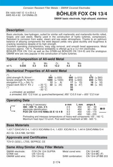
DescriptionBasic electrode, low-hydrogen, suited for similar soft martensitic and martensitic-ferritic rolled,forged, and cast steels. Mainly used in the construction of hydro turbines, compressors.Resistant to corrosion from water, steam and sea water atmosphere. Thanks to an optimumbalance of alloying components the weld deposit yields very good ductility and toughness &cracking resistance despite of its high strength. Excellent operating characteristics, easy slag removal, and smooth bead appearance. Metalrecovery approx. 130 %. Positional weldability is offered up to ø 3.2 mm electrodes.BÖHLER FOX CN 13/4 as well as the GTAW-rod BÖHLER CN 13/4-IG and the analogousGMAW wire are very popular in the construction of hydro turbines.
Approvals and CertificatesTÜV-D (3232.), LTSS, SEPROZ, CE
Same Alloy/Similar Alloy Filler MetalsSMAW electrode: FOX CN 13/4 SUPRA Metal cored wire: CN 13/4-MCGTAW rod: CN 13/4-IG CN 13/4-MC (F)GMAW solid wire: CN 13/4-IG SAW combination: CN 13/4-UP/BB 203
Base Materials1.4317 GX4CrNi13-4, 1.4313 X3CrNiMo13-4, 1.4351 X3CrNi13-4, 1.4414 GX4CrNiMo13-4
ACI Gr. CA 6 NM, S41500
Operating Datare-drying if necessary: ø mm L mm amps A300 - 350 °C, min. 2 h 2.5 350 60 - 190electrode identification: 3.2 450 90 - 130FOX CN 13/4 410 NiMo-25 E 13 4 B 4.0 450 120 - 170
5.0 450 160 - 220Preheating and interpass temperatures of heavy-wall components 100 - 160 °C. Maximum heat input 15 kJ/cm. Post weld heat treatment at 580 - 620 °C.
Mechanical Properties of All-weld Metal(*) u a q yield strength Re N/mm2: 890 (≥ 830) 680 (≥ 610) 670 (≥ 560)tensile strength Rm N/mm2: 1090 (≥ 1000) 910 (≥ 830) 850 (≥ 780)elongation A (L0 = 5d0) %: 12 (≥ 338) 17 (≥ 315) 18 (≥ 316)impact work ISO-V KV J + 20 °C: 32 (≥ 324) 66 (≥ 347) 95 (≥ 360)(*) - 20 °C: 55
- 60 °C: 50u untreated, as-welded; a annealed, 600 °C/2 h/air; q: quenched/tempered, 950 °C/0.5 h/air + 600 °C/2 h/air
Typical Composition of All-weld MetalC Si Mn Cr Ni Mo
wt-% 0.035 0.3 0.5 12.2 4.5 0.5
EN 1600:1997: E 13 4 B 6 2AWS A5.4-92: E410NiMo-25 BÖHLER FOX CN 13/4
SMAW basic electrode, high-alloyed, stainless
2-174
Corrosion Resistant Filler Metals – SMAW Covered Electrodes

DescriptionBasic electrode, core wire alloyed, low-hydrogen, suited for welding similar soft-martensitic andmartensitic-ferritic rolled, forged, and cast steels. Mainly used in the construction of hydro tur-bines, compressors. Resistant to corrosion from water, steam, and sea water atmosphere.Thanks to an optimum balance of alloying components the weld deposit yields very good duc-tility and toughness & cracking resistance despite of its high strength. Excellent slag removability, smooth bead appearance. Out of position weldable except verticaldown.
Approvals and CertificatesTÜV-D (9081.), SEPROZ, CE
Same Alloy/Similar Alloy Filler MetalsSMAW electrode: FOX CN 13/4 Metal cored wire: CN 13/4-MCGTAW rod: CN 13/4-IG CN 13/4-MC (F)GMAW solid wire: CN 13/4-IG SAW combination: CN 13/4-UP/BB 203
Base Materials1.4317 GX4CrNi13-4, 1.4313 X3CrNiMo13-4, 1.4351 X3CrNi13-4, 1.4414 GX4CrNiMo13-4
ACI Gr. CA 6 NM, S41500
Operating Datare-drying if necessary: ø mm L mm amps A300 - 350 °C, min. 2 h 3.2 350 90 - 110electrode identification: 4.0 350 120 - 145FOX CN 13/4 SUPRA 410NiMo-15 E 13 4 BPreheating and interpass temperatures of heavy-wall components 100 - 160 °C. Maximum heat input 15 kJ/cm. Post weld heat treatment at 580 - 620 °C.
Mechanical Properties of All-weld Metal(*) u a q yield strength Re N/mm2: 880 (≥ 830) 680 (≥ 610) 670 (≥ 560)tensile strength Rm N/mm2: 1060 (≥ 1000) 930 (≥ 830) 850 (≥ 760)elongation A (L0 = 5d0) %: 13 (≥ 338) 18 (≥ 315) 18 (≥ 316)impact work ISO-V KV J + 20 °C: 35 (≥ 330) 70 (≥ 355) 105 (≥ 370)
- 20 °C: 60- 60 °C: 55
(*) u untreated, as-weldeda annealed, 600 °C/2 h/airq quenched/tempered , 950 °C/0.5 h/air + 600 °C/2 h/air
Typical Composition of All-weld MetalC Si Mn Cr Ni Mo
wt-% 0.03 0.3 0.6 12.2 4.5 0.5
EN 1600:1997: E 13 4 B 4 2AWS A5.4-92: E410NiMo-15 BÖHLER
FOX CN 13/4 SUPRASMAW basic electrode, high-alloyed, stainless
2-175
Corrosion Resistant Filler Metals – SMAW Covered Electrodes

DescriptionBasic electrode, core wire alloyed, low-hydrogen, with good operating characteristics in all posi-tions except vertical-down. Mainly used for surfacing on sealing faces of gas, water and steamvalves to meet stainless and wear resistant overlays for instance. In the machined condition, atleast a two layer build up should remain. Joint welding of similar, stainless and heat resistantchromium steels provides matching colour of weld metal with very good ability to polishing.Retention of hardness up to +450 °C, scaling resistant up to +900 °C. Preheating and interpasstemperature 200 - 300 °C, post weld heat treatment at 700 - 750 °C depending on the weld job.
Approvals and CertificatesSEPROZ
Same Alloy Filler MetalsGMAW solid wire: KW 10-IG
Base Materialssurfacings: all weldable backing materials, unalloyed and low-alloyed
joint welds: corrosion resistant Cr-steels as well as other similar-alloyed steels withC-contents ≤ 0.20 % (repair welding); heat resistant Cr-steels of similar chemical composition. Be careful with dilution and welding technology.
1.4006 X12Cr13, 1.4021 X20Cr13
AISI 410, 420
Operating Datare-drying if necessary: ø mm L mm amps A120 - 200 °C, min. 2 h 2.5 300 60 - 180electrode identification: 3.2 350 80 - 100FOX KW 10 E 13 B 4.0 350 110 - 130
Mechanical Properties of All-weld Metal(*) u ayield strength Re N/mm2: 530 (≥ 450)tensile strength Rm N/mm2: 700 (≥ 640)elongation A (L0 = 5d0) %: 17 (≥ 315)Brinell-hardness HB: 350 210(*) u untreated, as-welded
a annealed, 750 °C/2 h/furnaceThe hardness of the deposit ist greatly influenced by the degree of dilution with the base metal (depending on the relevant welding conditions) and by its chemical composition. As a general rule it can be observed that the higher the degree of dilution and the C-content of the base metal, the higher the deposit hardness.
Typical Composition of All-weld MetalC Si Mn Cr
wt-% 0.08 0.7 0.8 13.5
EN 1600:1997:E 13 B 2 2AWS A5.4-92: E410-15 (mod.) BÖHLER FOX KW 10
SMAW basic electrode, high-alloyed, stainless
2-176
Corrosion Resistant Filler Metals – SMAW Covered Electrodes

DescriptionBasic electrode, core wire alloyed, low-hydrogen, with good operating characteristics in all posi-tions except vertical-down. Mainly used for surfacing on sealing faces of gas, water and steamvalves to meet stainless and wear resistant overlays for instance. In the machined condition, atleast a two layer build up should remain. Joint welding of similar, stainless and heat resistantchromium steels provides matching colour of weld metal with very good ability to polishing.Hydrogen content in weld deposit < 5 ml/100 g.Preheating and interpass temperature 200 - 300 °C, post weld heat treatment at 730 - 800 °C.
Approvals and CertificatesKTA 1408.1 (8098.00), SEPROZ, CE
Same Alloy/Similar Alloy Filler MetalsSMAW electrode: FOX SKWAM GMAW solid wire: KWA-IG
SKWA-IGSKWAM-IG
Base Materialssurfacings: all weldable backing materials, unalloyed and low-alloyed.
joint welds: corrosion resistant Cr-steels as well as other similar-alloyed steels with C-contents up to 0.20 % (repair welding). Be careful with dilution and welding technology.
1.4510 X3CrTi17
AISI 430Ti, 431
Operating Datare-drying if necessary: ø mm L mm amps A120 - 200 °C, min. 2 h 2.5 300 60 - 180electrode identification: 3.2 350 80 - 110FOX SKWA 430-15 E 17 B 4.0 350 110 - 140
5.0 450 140 - 180The hardness of the deposit ist greatly influenced by the degree of dilution with the base metal (depending on the relevant welding conditions) and by its chemical composition. As a general rule it can be observed that the higher the degree of dilution and the C-content of the base metal, the higher the deposit hardness.
Mechanical Properties of All-weld Metal(*) u ayield strength Re N/mm2: 370 (≥ 340)tensile strength Rm N/mm2: 560 (≥ 530)elongation A (L0 = 5d0) %: 23 (≥ 318)Brinell-hardness HB: 250 200(*) u untreated, as-welded
a annealed, 750 °C/2 h/furnace
Typical Composition of All-weld MetalC Si Mn Cr
wt-% 0.08 0.4 0.3 17.0
EN 1600:1997: E 17 B 2 2AWS A5.4-92: E430-15 BÖHLER FOX SKWA
SMAW basic electrode, high-alloyed, stainless
2-177
Corrosion Resistant Filler Metals – SMAW Covered Electrodes

DescriptionBasic electrode, core wire alloyed, low-hydrogen, with good operating characteristics in all posi-tions except vertical-down. Mainly used for surfacing on sealing faces of gas, water and steamvalves to meet stainless and wear resistant overlays for instance. In the machined condition, atleast a two layer build up should remain. Joint welding of similar, stainless and heat resistant chromium steels provides matching colourof weld metal with very good ability to polishing. Hydrogen content in weld deposit <5 ml/100 g. Weld metal retention of hardness up to +500 °C.Scaling resistant up to +900 °C.
Approvals and CertificatesKTA 1408.1 (8043.01), DB (30.014.12-20.014.08), ÖBB, SEPROZ, CE
Same Alloy/Similar Alloy Filler MetalsSMAW electrode: FOX SKWAGMAW solid wire: KWA-IG
SKWA-IGSKWAM-IG
Base Materialssurfacings: all weldable backing materials, unalloyed and low-alloyed.
joint welds: corrosion resistant Cr-steels as well as other similar-alloyed steels with C-contents up to 0.20 % (repair welding). Be careful with dilution and welding technology
Operating Datare-drying if necessary: ø mm L mm amps A120 - 200 °C, min. 2 h 2.5 300 60 - 180electrode identification: 3.2 350 80 - 110FOX SKWAM E Z 17 Mo B 4.0 350 110 - 140
5.0 450 140 - 180Preheating as required by the base metal, with temperatures between 100 and 200 °C being generally sufficient (forjoint welding operations 250 - 400 °C). Annealing at 650 - 750 °C may be carried out to improve the toughness valuesin the weld metal and in the transition zone of the base metal.
The hardness of the deposit ist greatly influenced by the degree of dilution with the base metal (depending on the relevant welding conditions) and by its chemical composition. As a general rule it can be observed that the higher the degree of dilution and the C-content of the base metal, the higher the deposit hardness.
Mechanical Properties of All-weld Metal(*) u aBrinell-hardness HB: 400 250(*) u untreated, as-welded
a annealed, 700° C/2 h/furnace
Typical Composition of All-weld MetalC Si Mn Cr Mo
wt-% 0.22 0.3 0.4 17.0 1.3
EN 1600:1997: E Z17 Mo B 2 2 BÖHLER FOX SKWAMSMAW basic electrode, high-alloyed, stainless
2-178
Corrosion Resistant Filler Metals – SMAW Covered Electrodes
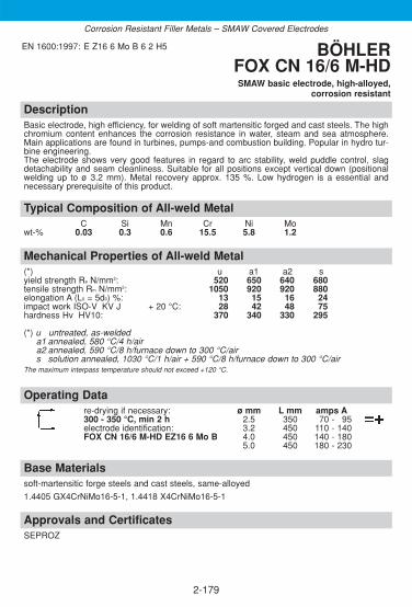
DescriptionBasic electrode, high efficiency, for welding of soft martensitic forged and cast steels. The highchromium content enhances the corrosion resistance in water, steam and sea atmosphere.Main applications are found in turbines, pumps-and combustion building. Popular in hydro tur-bine engineering.The electrode shows very good features in regard to arc stability, weld puddle control, slagdetachability and seam cleanliness. Suitable for all positions except vertical down (positionalwelding up to ø 3.2 mm). Metal recovery approx. 135 %. Low hydrogen is a essential andnecessary prerequisite of this product.
Approvals and CertificatesSEPROZ
Base Materialssoft-martensitic forge steels and cast steels, same-alloyed
1.4405 GX4CrNiMo16-5-1, 1.4418 X4CrNiMo16-5-1
Operating Datare-drying if necessary: ø mm L mm amps A300 - 350 °C, min 2 h 2.5 350 70 - 195electrode identification: 3.2 450 110 - 140FOX CN 16/6 M-HD EZ16 6 Mo B 4.0 450 140 - 180
5.0 450 180 - 230
Mechanical Properties of All-weld Metal(*) u a1 a2 syield strength Re N/mm2: 520 650 640 680tensile strength Rm N/mm2: 1050 920 920 880elongation A (L0 = 5d0) %: 13 15 16 24impact work ISO-V KV J + 20 °C: 28 42 48 75hardness Hv HV10: 370 340 330 295
(*) u untreated, as-weldeda1 annealed, 580 °C/4 h/aira2 annealed, 590 °C/8 h/furnace down to 300 °C/airs solution annealed, 1030 °C/1 h/air + 590 °C/8 h/furnace down to 300 °C/air
The maximum interpass temperature should not exceed +120 °C.
Typical Composition of All-weld MetalC Si Mn Cr Ni Mo
wt-% 0.03 0.3 0.6 15.5 5.8 1.2
EN 1600:1997: E Z16 6 Mo B 6 2 H5 BÖHLERFOX CN 16/6 M-HDSMAW basic electrode, high-alloyed,
corrosion resistant
2-179
Corrosion Resistant Filler Metals – SMAW Covered Electrodes

DescriptionBasic electrode with strength properties for joint and fabrication welding of analogous precipi-tation hardening Cr-Ni-Cu-alloyed rolled-, forged- and cast steels. Popular for components in the paper industry, rotors of compressors, fan blades, press platesin the plastic processing industry and for the aerospace industry. The electrode shows very good features in regard to arc stability, weld puddle control, slagdetachability and seam cleanliness. Lowest hydrogen content in the deposit is a prerequisite(HD < 5 ml/100 g). The electrode is suitable for welding in all positions except vertical down.The interpass temperature has to be kept very low (max. 80 °C). With the use of the properPWHT (solution annealing + precipitation hardening impact values down to -50 °C are stillachievable).
Approvals and CertificatesSEPROZ
Base Materialsprecipitation hardening forged steels and cast steels, same-alloyed
1.4540 X4CrNiCuNb16-4, 1.4540 GX4CrNiCuNb16-4, 1.4542 X5CrNiCuNb16-4,1.4548 X5CrNiCuNb17-4-4
J92180 Gr. CB Cu-1; S17400 Type 630; SAE J467 17-4PH
Operating Datare-drying if necessary: ø mm L mm amps A300 - 350 °C, min. 2 h 3.2 350 90 - 110electrode identification: 4.0 350 120 - 140FOX CN 17/4 PH E Z 17 4 Cu B
Mechanical Properties of All-weld Metal(*) u a1 a2 a3 s1 s2 yield strength Re N/mm2: 440 940 830 630 920 650tensile strength Rm N/mm2: 800 1030 1110 940 1030 890elongation A (L0 = 5d0) %: 4 10 8 15 17 18impact work ISO-V KV J + 20 °C: 35-40 20 15 24-30 60-66 69-75
- 50 °C: 55hardness HRC: 32-39 37-40 – 29-31 – 27-29(*) u untreated, as-welded a1 annealed, 540 °C/3 h/air
a2 annealed, 480 °C/1 h/air a3 annealed, 760 °C/2 h/air + 620 °C/4 h/airs1 solution annealed, 1040 °C/2 h/air + 580 °C/4 h/airs2 solution annealed, 1040 °C/0.5 h/air + 760 °C/2 h/air + 620 °C/4 h/air
Typical Composition of All-weld MetalC Si Mn Cr Ni Mo Cu Nb
wt-% 0.03 0.3 0.6 16.0 4.9 0.4 3.2 0.2
EN 1600:1997: E Z17 4 Cu B 4 3 H5AWS A5.4-92: E630-15 (mod.) BÖHLER
FOX CN 17/4 PHSMAW basic electrode, high-alloyed,
corrosion resistant
2-180
Corrosion Resistant Filler Metals – SMAW Covered Electrodes

DescriptionBasic stainless steel electrode. Designed to produce first class weld deposits with reliable CVNtoughness values down to -196 °C, 100 % X-Ray safety together with very good root pass andpositional welding characteristics, good gap bridging ability, easy weld pool and slag control aswell as easy slag removal even in narrow preparations resulting in clean bead surfaces andminimum post weld cleaning. An excellent electrode for welding on site! Resistant to intergranular corrosion up to +350 °C. Fully core wire alloyed and packed into hermetically sealed tins. This type of consumables is also available as a special low ferrite ver-sion. Due to the specific alloying concept and a controlled ferrite content of 3-5 FN the weldmetal provides excellent impact thoughness down to -196 °C along with lateral expansionvalues of >0.38 mm which makes it suitable for LNG applications as well.
Approvals and CertificatesTÜV-D (0152.), DB (30.014.10), ÖBB, TÜV-A (95), Statoil, SEPROZ, CE
Same Alloy / Similar Alloy Filler MetalsSMAW electrode: FOX EAS 2-A Metal cored wire: EAS 2-MC
FOX EAS 2-VD Flux cored wire: EAS 2-FDGTAW rod: EAS 2-IG EAS 2 PW-FDGMAW solid wire: EAS 2-IG (Si) EAS 2 PW-FD (LF)
SAW combination: EAS 2-UP/BB 202
Base Materials1.4306 X2CrNi19-11, 1.4301 X5CrNi18-10, 1.4311 X2CrNiN18-10, 1.4312 GX10CrNi18-8,1.4541 X6CrNiTi18-10, 1.4546 X5CrNiNb18-10, 1.4550 X6CrNiNb18-10
AISI 304, 304L, 304LN, 302, 321, 347; ASTM A157 Gr. C9; A320 Gr. B8C o. D
Operating Datare-drying if necessary: ø mm L mm amps A– 2.5 300 50 - 180electrode identification: 3.2 350 80 - 110FOX EAS 2 308L-15 E 19 9 L B 4.0 350 110 - 140
Mechanical Properties of All-weld Metal(*) uyield strength Re N/mm2: 410 (≥ 350)tensile strength Rm N/mm2: 560 (≥ 520)elongation A (L0 = 5d0) %: 40 (≥ 335)impact work ISO-V KV J + 20 °C: 110 (≥ 390)
- 196 °C: 50 (≥ 334)lateral expansion (mm) - 196 °C: (≥0.38)(*) u untreated, as-welded
Typical Composition of All-weld MetalC Si Mn Cr Ni
wt-% 0.03 0.4 1.3 19.5 10.5
EN 1600:1997:E 19 9 L B 2 2AWS A5.4-92: E308L-15 BÖHLER FOX EAS 2
SMAW basic electrode, high-alloyed,chemical resistant
2-181
Corrosion Resistant Filler Metals – SMAW Covered Electrodes

DescriptionRutile electrode, core wire alloyed, stainless steel. Preferably used for 1.4306 / 304L / 304LNsteel grades. BÖHLER FOX EAS 2-A is noted for its superior welding characteristics and metallurgy. Can beused on AC or DC. Other characteristics include high current carrying capacity, minimumspatter formation, self releasing slag, smooth and clean weld profile, safety against formationof porosity due to moisture resistant coating and packaging into hermetically sealed tins.Resistant to intergranular corrosion up to +350 °C.
Approvals and CertificatesTÜV-D (1095.), DB (30.014.15), ÖBB, TÜV-A (96), ABS (E 308L-17), GL (4306), Statoil, VUZ,SEPROZ, CE
Same Alloy/Similar Alloy Filler MetalsSMAW electrode: FOX EAS 2 Metal cored wire: EAS 2-MC
FOX EAS 2-VD Flux cored wire: EAS 2-FDGTAW rod: EAS 2-IG EAS 2 PW-FDGMAW solid wire: EAS 2-IG (Si) EAS 2 PW-FD (LF)
SAW combination: EAS 2-UP/BB 202
Base Materials1.4306 X2CrNi19-11, 1.4301 X5CrNi18-10, 1.4311 X2CrNiN18-10, 1.4312 GX10CrNi18-8,1.4541 X6CrNiTi18-10, 1.4546 X5CrNiNb18-10, 1.4550 X6CrNiNb18-10
AISI 304, 304L, 304LN, 302, 321, 347; ASTM A157 Gr. C9; A320 Gr. B8C or D
Operating Datare-drying if necessary: ø mm L mm amps A120 - 200 °C, min. 2 h 1.5 250 25 - 140electrode identification: 2.0 300 40 - 160FOX EAS 2-A 308L-17 E 19 9 L R 2.5 250/350 50 - 190
3.2 350 80 - 1204.0 350 110 - 1605.0 450 140 - 200
Mechanical Properties of All-weld Metal(*) u sayield strength Re N/mm2: 430 (≥ 350)tensile strength Rm N/mm2: 560 (≥ 520)elongation A (L0 = 5d0) %: 40 (≥ 335)impact work ISO-V KV J + 20 °C: 70 (≥ 347)
- 120 °C: (≥ 332)- 196 °C: (≥ 332)
(*) u untreated, as-weldedsa solution annealed and quenched
Typical Composition of All-weld MetalC Si Mn Cr Ni
wt-% 0.03 0.8 0.8 19.8 10.2
EN 1600:1997:E 19 9 L R 3 2AWS A5.4-92: E308L-17 BÖHLER FOX EAS 2-A
SMAW rutile electrode, high-alloyed,chemical resistant
2-182
Corrosion Resistant Filler Metals – SMAW Covered Electrodes

DescriptionRutile basic electrode, core wire alloyed, stainless steel, especially designed for vertical-downwelding in the sheet metal fabrication.Highly economical due to fast travel speeds. 50 % time saving is achieved compared to wel-ding in vertical up position with same electrode diameter. The extremely low heat helps to redu-ce distortion and associated straightening work. The product is resistant to intergranular corrosion up to service temperatures of +350 °C.
Approvals and CertificatesSEPROZ
Base Materials1.4306 X2CrNi19-11, 1.4301 X5CrNi18-10, 1.4311 X2CrNiN18-10, 1.4312 GX10CrNi18-8,1.4541 X6CrNiTi18-10, 1.4546 X5CrNiNb18-10, 1.4550 X6CrNiNb18-10
AISI 304, 304L, 304LN, 302, 321, 347; ASTM A157 Gr. C9; A320 Gr. B8C or D
Operating Datare-drying if necessary: ø mm L mm amps A120 - 200 °C, min. 2 h 2.5 300 75 - 185electrode identification: 3.2 300 105 - 115FOX EAS 2-VD 308L-17 E 19 9 L R
Mechanical Properties of All-weld Metal(*) uyield strength Re N/mm2: 470 (≥ 350)tensile strength Rm N/mm2: 600 (≥ 520)elongation A (L0 = 5d0) %: 36 (≥ 335)impact work ISO-V KV J + 20 °C: 55 (≥ 347)
- 120 °C: (≥ 332)(*) u untreated, as-welded
Typical Composition of All-weld MetalC Si Mn Cr Ni
wt-% 0.02 0.7 0.7 19.8 10.5
EN 1600:1997:E 19 9 L R 1 5AWS A5.4-92: E308L-17 BÖHLER FOX EAS 2-VD
SMAW rutile electrode, high-alloyed,chemical resistant
2-183
Same Alloy/Similar Alloy Filler MetalsSMAW electrode: FOX EAS 2 Metal cored wire: EAS 2-MC
FOX EAS 2-A Flux cored wire: EAS 2-FDGTAW rod: EAS 2-IG EAS 2 PW-FDGMAW solid wire: EAS 2-IG (Si) EAS 2 PW-FD (LF)
SAW combination: EAS 2-UP/BB 202
Corrosion Resistant Filler Metals – SMAW Covered Electrodes
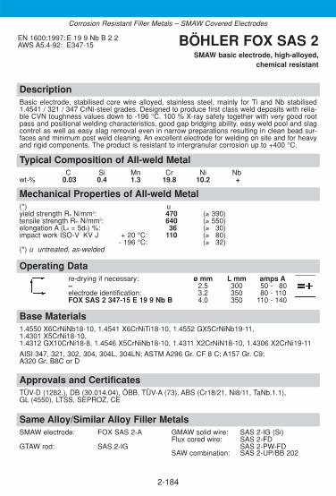
DescriptionBasic electrode, stabilised core wire alloyed, stainless steel, mainly for Ti and Nb stabilised1.4541 / 321 / 347 CrNi-steel grades. Designed to produce first class weld deposits with relia-ble CVN toughness values down to -196 °C. 100 % X-ray safety together with very good rootpass and positional welding characteristics, good gap bridging ability, easy weld pool and slagcontrol as well as easy slag removal even in narrow preparations resulting in clean bead sur-faces and minimum post weld cleaning. An excellent electrode for welding on site and for heavyand rigid components. The product is resistant to intergranular corrosion up to +400 °C.
Approvals and CertificatesTÜV-D (1282.), DB (30.014.04), ÖBB, TÜV-A (73), ABS (Cr18/21, Ni8/11, TaNb.1.1), GL (4550), LTSS, SEPROZ, CE
Base Materials1.4550 X6CrNiNb18-10, 1.4541 X6CrNiTi18-10, 1.4552 GX5CrNiNb19-11, 1.4301 X5CrNi18-10,1.4312 GX10CrNi18-8, 1.4546 X5CrNiNb18-10, 1.4311 X2CrNiN18-10, 1.4306 X2CrNi19-11
AISI 347, 321, 302, 304, 304L, 304LN; ASTM A296 Gr. CF 8 C; A157 Gr. C9; A320 Gr. B8C or D
Operating Datare-drying if necessary: ø mm L mm amps A– 2.5 300 50 - 180electrode identification: 3.2 350 80 - 110FOX SAS 2 347-15 E 19 9 Nb B 4.0 350 110 - 140
Mechanical Properties of All-weld Metal(*) uyield strength Re N/mm2: 470 (≥ 390)tensile strength Rm N/mm2: 640 (≥ 550)elongation A (L0 = 5d0) %: 36 (≥ 330)impact work ISO-V KV J + 20 °C: 110 (≥ 380)
- 196 °C: (≥ 332)(*) u untreated, as-welded
Typical Composition of All-weld MetalC Si Mn Cr Ni Nb
wt-% 0.03 0.4 1.3 19.8 10.2 +
EN 1600:1997: E 19 9 Nb B 2 2AWS A5.4-92: E347-15 BÖHLER FOX SAS 2
SMAW basic electrode, high-alloyed,chemical resistant
2-184
Same Alloy/Similar Alloy Filler MetalsSMAW electrode: FOX SAS 2-A GMAW solid wire: SAS 2-IG (Si)
Flux cored wire: SAS 2-FDGTAW rod: SAS 2-IG SAS 2-PW-FD
SAW combination: SAS 2-UP/BB 202
Corrosion Resistant Filler Metals – SMAW Covered Electrodes
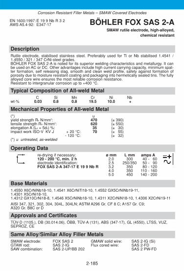
DescriptionRutile electrode, stabilised stainless steel. Preferably used for Ti or Nb stabilised 1.4541 /1.4550 / 321 / 347 CrNi-steel grades.BÖHLER FOX SAS 2-A is noted for its superior welding characteristics and metallurgy. It canbe used on AC or DC. Other advantages include high current carrying capacity, minimum spat-ter formation, self releasing slag, smooth and clean weld profile, safety against formation ofporosity due to moisture resistant coating and packaging into hermetically sealed tins. The fullyalloyed core wire ensures the most reliable corrosion resistance.Resistant to intergranular corrosion up to +400 °C.
Approvals and CertificatesTÜV-D (1105.), DB (30.014.06), ÖBB, TÜV-A (131), ABS (347-17), GL (4550), LTSS, VUZ,SEPROZ, CE
Base Materials1.4550 X6CrNiNb18-10, 1.4541 X6CrNiTi18-10, 1.4552 GX5CrNiNb19-11, 1.4301 X5CrNi18-10,1.4312 GX10CrNi18-8, 1.4546 X5CrNiNb18-10, 1.4311 X2CrNiN18-10, 1.4306 X2CrNi19-11
AISI 347, 321, 302, 304, 304L, 304LN; ASTM A296 Gr. CF 8 C; A157 Gr. C9; A320 Gr. B8C or D
Operating Datare-drying if necessary: ø mm L mm amps A120 - 200 °C, min. 2 h 2.0 300 40 - 160electrode identification: 2.5 250/350 50 - 190FOX SAS 2-A 347-17 E 19 9 Nb R 3.2 350 80 - 120
4.0 350 110 - 1605.0 450 140 - 200
Mechanical Properties of All-weld Metal(*) uyield strength Re N/mm2: 470 (≥ 390)tensile strength Rm N/mm2: 620 (≥ 550)elongation A (L0 = 5d0) %: 35 (≥ 330)impact work ISO-V KV J + 20 °C: 70 (≥ 355)
- 120 °C: (≥ 332)(*) u untreated, as-welded
Typical Composition of All-weld MetalC Si Mn Cr Ni Nb
wt-% 0.03 0.8 0.8 19.5 10.0 +
EN 1600:1997: E 19 9 Nb R 3 2AWS A5.4-92: E347-17 BÖHLER FOX SAS 2-A
SMAW rutile electrode, high-alloyed,chemical resistant
2-185
Same Alloy/Similar Alloy Filler MetalsSMAW electrode: FOX SAS 2 GMAW solid wire: SAS 2-IG (Si)GTAW rod: SAS 2-IG Flux cored wire: SAS 2-FDSAW combination: SAS 2-UP/BB 202 SAS 2 PW-FD
Corrosion Resistant Filler Metals – SMAW Covered Electrodes

DescriptionBasic electrode, core wire alloyed, stainless steel. Preferably used for 1.4435 / 316L steel gra-des.BÖHLER FOX EAS 4 M is designed to produce high quality weld deposits with reliable tough-ness values down to – 196 °C. 100 % X-ray safety together with very good root pass and posi-tional welding characteristics. Good gap bridging ability, easy weld pool and slag control. Easyslag removal even in narrow preparations result in clean bead surfaces with minimum post weldcleaning. Ideal electrode for welding on site. Electrodes are packed in hermetically sealed tinsand have a moisture resistant coating. Resistant to intergranular corrosion up to +400 °C.
Approvals and CertificatesTÜV-D (0772.), ÖBB, TÜV-A (99), DNV (316), Statoil, SEPROZ, CE
Base Materials1.4401 X5CrNiMo17-12-2, 1.4404 X2CrNiMo17-12-2, 1.4435 X2CrNiMo18-14-3, 1.4436 X3CrNiMo17-13-3, 1.4571 X6CrNiMoTi17-12-2, 1.4580 X6CrNiMoNb17-12-2,1.4583 X10CrNiMoNb18-12, 1.4409 GX2CrNiMo 19-11-2
S31653; AISI 316L, 316Ti, 316Cb
Operating Datare-drying if necessary: ø mm L mm amps A– 2.5 300 50 - 180electrode identification: 3.2 350 80 - 110FOX EAS 4 M 316L-15 E 19 12 3 L B 4.0 350 110 - 140
Mechanical Properties of All-weld Metal(*) uyield strength Re N/mm2: 460 (≥ 350)tensile strength Rm N/mm2: 600 (≥ 540)elongation A (L0 = 5d0) %: 38 (≥ 335)impact work ISO-V KV J + 20 °C: 90 (≥ 380)
- 120 °C: (≥ 332)- 196 °C: (≥ 327)
(*) u untreated, as-welded
Typical Composition of All-weld MetalC Si Mn Cr Ni Mo
wt-% 0.03 0.4 1.2 18.8 11.8 2.7
EN 1600:1997: E 19 12 3 L B 2 2AWS A5.4-92: E316L-15 BÖHLER FOX EAS 4 M
SMAW basic electrode, high-alloyed,chemical resistant
2-186
Same Alloy/Similar Alloy Filler MetalsSMAW electrode: FOX EAS 4 M-A GMAW solid wire: EAS 4 M-IG (Si)
FOX EAS 4 M-VD Metal cored wire: EAS 4 M-MCFOX EAS 4 M-TS Flux cored wire: EAS 4 M-FDFOX EAS 4 M (LF) EAS 4 PW-FD
GTAW rod: EAS 4 M-IG EAS 4 PW-FD (LF)SAW combination: EAS 4 M-UP/BB 202
Corrosion Resistant Filler Metals – SMAW Covered Electrodes

DescriptionBasic electrode, core wire alloyed, stainless steel. Preferably used for 1.4435 / 316L steel gra-des. Controlled delta ferrite content (3-8 FN). BÖHLER FOX EAS 4 M (LF) is designed to pro-duce high quality weld deposits with reliable tough-ness values down to -196 °C. 100 % X-raysafety together with very good root pass and positional welding characteristics. Good gap brid-ging ability, easy weld pool and slag control. Easy slag removal even in narrow preparationsresult in clean bead surfaces with minimum post weld cleaning. Ideal electrode for welding onsite. Electrodes are packed in hermetically sealed tins and have a moisture resistant coating.Resistant to intergranular corrosion up to +400 °C.
Approvals and CertificatesDNV (316)
Base Materials1.4401 X5CrNiMo17-12-2, 1.4404 X2CrNiMo17-12-2, 1.4409 GX2CrNiMo 19-11-2
S31653; AISI 316L
Operating Datare-drying if necessary: ø mm L mm amps A– 2.5 300 50 - 180electrode identification: 3.2 350 80 - 110FOX EAS 4 M LF 316L-15 4.0 350 110 - 140
Mechanical Properties of All-weld Metal(*) uyield strength Re N/mm2: 430 (≥ 350)tensile strength Rm N/mm2: 570 (≥ 510)elongation A (L0 = 5d0) %: 38 (≥ 330)impact work ISO-V KV J + 20 °C: 100 (≥ 380)
- 120 °C: (≥ 332)- 196 °C: 55 (≥ 327)
lateral expansion (mm) - 196 °C: (≥0.38)(*) u untreated, as-welded
Typical Composition of All-weld MetalC Si Mn Cr Ni Mo
wt-% 0.03 0.4 1.2 18.5 12.8 2.4
EN 1600:1997: E Z19 12 3 L B 2 2AWS A5.4-92: E316L-15 BÖHLER
FOX EAS 4 M (LF) SMAW basic electrode, high-alloyed,
chemical resistant
2-187
Same Alloy/Similar Alloy Filler MetalsSMAW electrode: FOX EAS 4 M-A GMAW solid wire: EAS 4 M-IG (Si)
FOX EAS 4 M-VD Metal cored wire: EAS 4 M-MCFOX EAS 4 M-TS Flux cored wire: EAS 4 M-FD
GTAW rod: EAS 4 M-IG EAS 4 PW-FDEAS 4 PW-FD (LF)
SAW combination: EAS 4 M-UP/BB 202
Corrosion Resistant Filler Metals – SMAW Covered Electrodes

DescriptionRutile electrode, core wire alloyed, stainless steel. Preferably used for 1.4435 / 316L steel gra-des. BÖHLER FOX EAS 4 M-A is an acknowledged world leader, noted for its superior weldingcharacteristics and metallurgy. It can be used on AC or DC. Other advantages include high cur-rent capacity, minimum spatter formation, self releasing slag, smooth and clean weld profile,safety against formation of porosity due to moisture resistant coating and packaging into her-metically sealed tins.The fully alloyed core wire ensures the most reliable corrosion resistance. Resistant to inter-granular corrosion up to +400 °C.
Approvals and CertificatesTÜV-D (0773.), DB (30.014.14), ÖBB, TÜV-A (33), ABS (E 316L-17), DNV (316L), GL (4571), LR (316Lm), Statoil, VUZ, SEPROZ, CE
Base Materials1.4401 X5CrNiMo17-12-2, 1.4404 X2CrNiMo17-12-2, 1.4435 X2CrNiMo18-14-3,1.4436 X3CrNiMo17-13-3, 1.4571 X6CrNiMoTi17-12-2, 1.4580 X6CrNiMoNb17-12-2,1.4583 X10CrNiMoNb18-12, 1.4409 GX2CrNiMo 19-11-2
S31653, AISI 316L, 316Ti, 316Cb
Operating Datare-drying if necessary: ø mm L mm amps A120 - 200 °C, min. 2 h 1.5 250 25 - 140electrode identification: 2.0 300 40 - 160FOX EAS 4 M-A 316L-17 E 19 12 3 L R 2.5 250/350 50 - 190
3.2 350 80 - 1204.0 350/450 110 - 1605.0 450 140 - 200
Mechanical Properties of All-weld Metal(*) uyield strength Re N/mm2: 460 (≥ 350)tensile strength Rm N/mm2: 600 (≥ 540)elongation A (L0=5d0) %: 36 (≥ 330)impact work ISO-V KV J + 20 °C: 70 (≥ 347)
- 120 °C: (≥ 332)(*) u untreated, as-welded
Typical Composition of All-weld MetalC Si Mn Cr Ni Mo
wt-% 0.03 0.8 0.8 18.8 11.5 2.7
EN 1600:1997: E 19 12 3 L R 3 2AWS A5.4-92: E316L-17 BÖHLER FOX EAS 4 M-A
SMAW rutile electrode, high-alloyed,chemical resistant
2-188
Same Alloy/Similar Alloy Filler MetalsSMAW electrode: FOX EAS 4 M GMAW solid wire: EAS 4 M-IG (Si)
FOX EAS 4 M-VD Metal cored wire: EAS 4 M-MCFOX EAS 4 M-TS Flux cored wire: EAS 4 M-FDFOX EAS 4 M (LF) EAS 4 PW-FD
GTAW rod: EAS 4 M-IG EAS 4 PW-FD (LF)SAW combination: EAS 4 M-UP/BB 202
Corrosion Resistant Filler Metals – SMAW Covered Electrodes
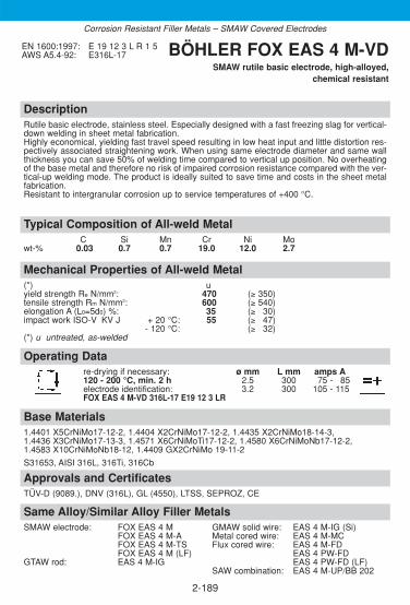
DescriptionRutile basic electrode, stainless steel. Especially designed with a fast freezing slag for vertical-down welding in sheet metal fabrication.Highly economical, yielding fast travel speed resulting in low heat input and little distortion res-pectively associated straightening work. When using same electrode diameter and same wallthickness you can save 50% of welding time compared to vertical up position. No overheatingof the base metal and therefore no risk of impaired corrosion resistance compared with the ver-tical-up welding mode. The product is ideally suited to save time and costs in the sheet metalfabrication. Resistant to intergranular corrosion up to service temperatures of +400 °C.
Approvals and CertificatesTÜV-D (9089.), DNV (316L), GL (4550), LTSS, SEPROZ, CE
Base Materials1.4401 X5CrNiMo17-12-2, 1.4404 X2CrNiMo17-12-2, 1.4435 X2CrNiMo18-14-3,1.4436 X3CrNiMo17-13-3, 1.4571 X6CrNiMoTi17-12-2, 1.4580 X6CrNiMoNb17-12-2,1.4583 X10CrNiMoNb18-12, 1.4409 GX2CrNiMo 19-11-2
S31653, AISI 316L, 316Ti, 316Cb
Operating Datare-drying if necessary: ø mm L mm amps A120 - 200 °C, min. 2 h 2.5 300 75 - 185electrode identification: 3.2 300 105 - 115FOX EAS 4 M-VD 316L-17 E19 12 3 LR
Mechanical Properties of All-weld Metal(*) uyield strength Re N/mm2: 470 (≥ 350)tensile strength Rm N/mm2: 600 (≥ 540)elongation A (L0=5d0) %: 35 (≥ 330)impact work ISO-V KV J + 20 °C: 55 (≥ 347)
- 120 °C: (≥ 332)(*) u untreated, as-welded
Typical Composition of All-weld MetalC Si Mn Cr Ni Mo
wt-% 0.03 0.7 0.7 19.0 12.0 2.7
EN 1600:1997: E 19 12 3 L R 1 5AWS A5.4-92: E316L-17 BÖHLER FOX EAS 4 M-VD
SMAW rutile basic electrode, high-alloyed,chemical resistant
2-189
Same Alloy/Similar Alloy Filler MetalsSMAW electrode: FOX EAS 4 M GMAW solid wire: EAS 4 M-IG (Si)
FOX EAS 4 M-A Metal cored wire: EAS 4 M-MCFOX EAS 4 M-TS Flux cored wire: EAS 4 M-FDFOX EAS 4 M (LF) EAS 4 PW-FD
GTAW rod: EAS 4 M-IG EAS 4 PW-FD (LF)SAW combination: EAS 4 M-UP/BB 202
Corrosion Resistant Filler Metals – SMAW Covered Electrodes

DescriptionRutile basic electrode, low carbon, stainless steel, particulary designed for site welding of tinwalled tubes and sheets. The very stable arc produces an excellent root penetration, bead con-figuration and gap bridging ability on DC electrode negative even when welding with a lowamperage. BÖHLER FOX EAS 4 M-TS is a good economical alternative to GTAW welding ondifficult accessible on-site welding applications. High safety against formation of porosity bymoisture resistant coating and packaging into hermetically sealed tin. The product is resistant to intergranular corrosion up to service temperatures of +400 °C.
Approvals and CertificatesTÜV-D (5625.), TÜV-A (615), SEPROZ, CE
Base Materials1.4401 X5CrNiMo17-12-2, 1.4404 X2CrNiMo17-12-2, 1.4435 X2CrNiMo18-14-3,1.4436 X3CrNiMo17-13-3, 1.4571 X6CrNiMoTi17-12-2, 1.4580 X6CrNiMoNb17-12-2,1.4583 X10CrNiMoNb18-12, 1.4409 GX2CrNiMo 19-11-2
S31653, AISI 316L, 316Ti, 316Cb
Operating Datare-drying if necessary: ø mm L mm amps A120 - 200 °C, min. 2 h 2.0 300 35 - 160electrode identification: 2.5 350 45 - 170FOX EAS 4 M-TS E 19 12 3 LR 3.2 350 50 - 110
Mechanical Properties of All-weld Metal(*) uyield strength Re N/mm2: 510 (≥ 350)tensile strength Rm N/mm2: 630 (≥ 540)elongation A (L0=5d0) %: 35 (≥ 330)impact work ISO-V KV J + 20 °C: 60 (≥ 347)
- 120 °C: (≥ 332)(*) u untreated, as-welded
Typical Composition of All-weld MetalC Si Mn Cr Ni Mo
wt-% 0.03 0.7 0.8 19.4 11.8 2.7
EN 1600:1997: E 19 12 3 L R 1 2AWS A5.4-92: E316L-16 (mod.) BÖHLER FOX EAS 4 M-TS
SMAW rutile electrode, high-alloyed,chemical resistant
2-190
Same Alloy/Similar Alloy Filler MetalsSMAW electrode: FOX EAS 4 M GMAW solid wire: EAS 4 M-IG (Si)
FOX EAS 4 M-A Metal cored wire: EAS 4 M-MCFOX EAS 4 M-VD Flux cored wire: EAS 4 M-FDFOX EAS 4 M (LF) EAS 4 PW-FD
GTAW rod: EAS 4 M-IG EAS 4 PW-FD (LF)SAW combination: EAS 4 M-UP/BB 202
Corrosion Resistant Filler Metals – SMAW Covered Electrodes
DC minus for root pass

DescriptionBasic electrode, stabilised core wire alloyed, stainless steel, mainly for Ti and Nb stabilised1.4571 / 1.4580 / 316Ti steel grades. BÖHLER FOX SAS 4 is designed to produce first class weld deposits with reliable CVN tough-ness values down to -90°C, 100% X-ray safety together with very good root pass and positio-nal welding characteristics, good gap bridging ability, easy weld pool and slag control as wellas easy slag removal even in narrow preparations resulting in clean bead surfaces and mini-mum post weld cleaning. An excellent electrode for welding on site and for heavy and rigid com-ponents.The product is resistant to intergranular corrosion up to +400 °C.
Approvals and CertificatesTÜV-D (0774.), DB (30.014.05), ÖBB, TÜV-A (132), ABS (Cr17/20, Ni10/13), GL (4571), SEPROZ, CE
Base Materials1.4571 X6CrNiMoTi17-12-2, 1.4580 X6CrNiMoNb17-12-2, 1.4401 X5CrNiMo17-12-2,1.4581 GX5CrNiMoNb19-11-2, 1.4437 GX6CrNiMo18-12, 1.4583 X10CrNiMoNb18-12,1.4436 X3CrNiMo17-13-3
AISI 316L, 316Ti, 316Cb
Operating Datare-drying if necessary: ø mm L mm amps A– 2.5 300 50 - 180electrode identification: 3.2 350 80 - 110FOX SAS 4 318-15 E 19 12 3 Nb B 4.0 350 110 - 140
Mechanical Properties of All-weld Metal(*) uyield strength Re N/mm2: 490 (≥ 390)tensile strength Rm N/mm2: 660 (≥ 600)elongation A (L0 = 5d0) %: 31 (≥ 328)impact work ISO-V KV J + 20 °C: 120 (≥ 100)
- 90 °C: (≥ 332)(*) u untreated, as-welded
Typical Composition of All-weld MetalC Si Mn Cr Ni Mo Nb
wt-% 0.03 0.4 1.3 18.8 11.8 2.7 +
EN 1600:1997: E 19 12 3 Nb B 2 2AWS A5.4-92: E318-15 BÖHLER FOX SAS 4
SMAW basic electrode, high-alloyed,chemical resistant
2-191
Same Alloy/Similar Alloy Filler MetalsSMAW electrode: FOX SAS 4-A GMAW solid wire: SAS 4-IG (Si)GTAW rod: SAS 4-IG Flux cored wire: SAS 4-FD
SAS 4 PW-FDSAW combination: SAS 4-UP/BB 202
Corrosion Resistant Filler Metals – SMAW Covered Electrodes

DescriptionRutile electrode, stabilised stainless steel. Preferably used for Ti or Nb stabilised 1.4571 / 1.4580/ 316Ti CrNiMo steel grades.BÖHLER FOX SAS 4-A is noted for its superior welding characteristics and metallurgy. It canbe used on AC or DC. Other characteristics include high current carrying capacity, minimumspatter formation, self releasing slag, smooth and clean weld profile, safety against formationof porosity due to moisture resistant coating and packaging into hermetically sealed tins. Thefully alloyed core wire ensures the most reliable corrosion resistance.Resistant to intergranular corrosion up to +400 °C.
Approvals and CertificatesTÜV-D (0777.), DB (30.014.07), ÖBB, TÜV-A (133), LTSS, VUZ, SEPROZ, CE
Base Materials1.4571 X6CrNiMoTi17-12-2, 1.4580 X6CrNiMoNb17-12-2, 1.4401 X5CrNiMo17-12-2,1.4581 GX5CrNiMoNb19-11-2, 1.4437 GX6CrNiMo18-12, 1.4583 X10CrNiMoNb18-12,1.4436 X3CrNiMo17-13-3
AISI 316L, 316Ti, 316Cb
Operating Datare-drying if necessary: ø mm L mm amps A120 - 200 °C, min. 2 h 2.0 300 40 - 160electrode identification: 2.5 250/350 50 - 190FOX SAS 4-A 318-17 E 19 12 3 Nb R 3.2 350 80 - 120
4.0 350 110 - 1605.0 450 140 - 200
Mechanical Properties of All-weld Metal(*) uyield strength Re N/mm2: 490 (≥ 390)tensile strength Rm N/mm2: 640 (≥ 550)elongation A (L0 = 5d0) %: 32 (≥ 330)impact work ISO-V KV J + 20 °C: 60 (≥ 347)
- 90 °C: (≥ 332)(*) u untreated, as-welded
Typical Composition of All-weld MetalC Si Mn Cr Ni Mo Nb
wt-% 0.03 0.8 0.8 19.0 12.0 2.7 +
EN 1600:1997: E 19 12 3 Nb R 3 2AWS A5.4-92: E318-17 BÖHLER FOX SAS 4-A
SMAW rutile electrode, high-alloyed,chemical resistant
2-192
Same Alloy/Similar Alloy Filler MetalsSMAW electrode: FOX SAS 4 GMAW solid wire: SAS 4-IG (Si)GTAW rod: SAS 4-IG Flux cored wire: SAS 4-PW
SAS 4 PW-FDSAW combination: SAS 4-UP/BB 202
Corrosion Resistant Filler Metals – SMAW Covered Electrodes

DescriptionBasic electrode, core wire alloyed, for joint welding of the special steel X2CrNiSi1815, 1.4361(BÖHLER A 610), which resists the attack of highly concentrated nitric acid as well as of nitric acidwhich additionally contains strong deoxidants. Also recommended for weld cladding of analogoustype steels. Suitable for use at service temperatures up to +350 °C.
Approvals and CertificatesTÜV-D (1482.), SEPROZ, CE
Base Materials1.4361 X1CrNiSi18-15-4, UNS S30600
Operating Datare-drying if necessary: ø mm L mm amps A300-350 °C, min. 2 h 2.5 300 40 - 170electrode identification: 3.2 350 70 - 100FOX EAS 2 Si E Z 19 14 Si B
Electrodes have to be welded with short arc. Amperage has to be adapted to wall thickness respectively welding posi-tion, to avoid overheated weld metal. For welding position PA/1G, 1F stringer beads are recommended.Heat input should be restricted to a necessary minimum, additional cooling is recommend to improve corrosion results.Reduce heat input in position PF/3G to avoid negative influence of corrosion behaviour of root pass and heat affectedzone, with limitation of weaving width of max. 2 x core wire diameter. Interpass temperature should not exceed 150°C.Grind out the end craters and grind previous passes. The TIG process, using EASN 2 Si-IG should be given prefe-rence for root welding. The weld metal does not require postweld heat treatment. In exceptional cases quench from+1100 °C in water.
Mechanical Properties of All-weld Metal(*) uyield strength Re N/mm2: 500 (≥ 390)tensile strength Rm N/mm2: 720 (≥ 660)elongation A (L0=5d0) %: 35 (≥ 330)impact work ISO-V KV J + 20 °C: 75 (≥ 347)
- 50 °C: (≥ 332)(*) u untreated, as-welded
Typical Composition of All-weld MetalC Si Mn Cr Ni
wt-% < 0.02 4.4 1.1 19.0 15.2
EN 1600:1997: E Z19 14 Si B 2 2ISO 3581: E 17.12 SiB BÖHLER FOX EAS 2 Si
SMAW basic electrode, high-alloyed, high corrosion resistant
2-193
Same Alloy/Similar Alloy Filler MetalsGTAW rod: EASN 2 Si-IG
Corrosion Resistant Filler Metals – SMAW Covered Electrodes

2-194
DescriptionRutile electrode, core wire alloyed, suited for corrosion resistant, CrNiMo(N)-steels. It satisfiesthe high demands of offshore fabricators, shipyards building chemical tankers as well as thechemical / petrochemical, pulp and paper industries. Suitable for service temperatures from -60 to +300 °C. The weld metal exhibits resistance against pitting corrosion and intergranularcorrosion resistance up to 300 °C (ASTM A 262 / Practice E)Good operating characteristics on AC and DC, minimum spatter formation, self releasing slagwith smooth and clean bead surface. BÖHLER FOX E 317 L is recommended for wall thick-nesses up to 30 mm.
Approvals and CertificatesBV (317L), LR (317L)
Same Alloy/Similar Alloy Filler MetalsGMAW flux cored wire: E317L-FD
E 317L PW-FDSAW combination: ASN 5 SY-UP/BB 202
Base MaterialsCrNiMo-steels with higher Mo-content like grade AISI 317L or corrosion resistant claddingson mild steels
1.4435 X2CrNiMo18-14-3, 1.4429 X2CrNiMoN17-13-3, 1.4438 X 2 CrNiMo 18-15-4
AISI 316L, 316 LN, 317LN, 317L
Operating Datare-drying if necessary: ø mm L mm amps A120-200°C, min. 2 h 2.5 300/350 55-85electrode identification: 3.2 350 80-115FOX E317 L 317L-17 4.0 350 110-155
Preheating and post weld heat treatment is not required by the weld deposit. The interpasstemperature should be kept below 150 °C.
Mechanical Properties of All-weld Metal(*) ayield strength Re N/mm2: 460 (≥ 400)tensile strength Rm N/mm2: 610 (≥ 580)elongation A (L0=5d0) %: 35 (≥ 30)impact work ISO-V KV J +20 °C: 65 (≥ 47)
-20 °C: 55-60 °C: 47 (≥ 32)
(*) u untreated, as-welded
Typical Composition of All-weld MetalC Si Mn Cr Ni Mo N FN
wt-% 0.03 0.8 0.9 19.0 13.0 3.6 + 4-12
AWS A5.4-92: E317L-17 BÖHLER FOX E317 LSMAW rutile electrode
high-alloyed, high corrosion resistant
Corrosion Resistant Filler Metals – SMAW Covered Electrodes

DescriptionBasic (with rutile contents) electrode, core wire alloyed, for corrosion resistant CrNi steels withincreased Mo-contents like 1.4439 / 317L. Suited for difficult corrosion conditions encountered e.g. in thechemical industry, flue gas de-sulphurisation plants, sea water desalinisation plants and particularly in thepaper, pulp and textile industries. It is characterised by an increased Mo content (4.5 %) to compensate forsegregation in high molybdenum alloyed weld metals to meet equivalent corrosion properties as the relevantbase metals with 3-4 % Mo guarantee. The weld metal features excellent chemical resistance to stress corrosion cracking as well as high pitting resistance. Intergranular corrosion resistance at operating tempe-ratures up to +300 °C. Excellent cryogenic toughness down to -269 °C. The electrode provides easy slagremoval with smooth and clean bead surfaces as well as good positional weldability.
Approvals and CertificatesTÜV-D (00016.), TÜV-A (496), DNV (317), GL (4439), SEPROZ, CE
Base Materials1.4436 X3CrNiMo17-13-3, 1.4439 X2CrNiMoN17-13-5, 1.4429 X2CrNiMoN17-13-3,1.4438 X2CrNiMo18-15-4, 1.4583 X10CrNiMoNb18-12
AISI 316Cb, 316LN, 317LN, 317L, UNS S31726
Operating Datare-drying if necessary: ø mm L mm amps A250 - 300 °C, min. 2 h 2.5 300 50 - 180electrode identification: 3.2 350 80 - 110FOX ASN 5 E 18 16 5 N L B 4.0 350 110 - 140
Interpass temperature should not exceed + 150 °C. Maximum width of weaving should be limited to twice the corewire diameter of the electrode. The arc should be kept short. Root pass welding is preferably carried out by the GTAW process, using ASN 5-IG welding wire.
Mechanical Properties of All-weld Metal(*) uyield strength Re N/mm2: 460 (≥ 400)tensile strength Rm N/mm2: 660 (≥ 590)elongation A (L0 = 5d0) %: 35 (≥ 330)impact work ISO-V KV J + 20 °C: 100 (≥ 390)
- 269 °C: 42 (≥ 332)(*) u untreated, as-welded
Typical Composition of All-weld MetalC Si Mn Cr Ni Mo N PREN FN
wt-% ≤ 0.04 0.5 2.5 18.5 17.0 4.3 0.17 36.3 ≤ 0.5
EN 1600:1997: E 18 16 5 N L B 2 2AWS A5.4-92: E317LN-15 (mod.) BÖHLER FOX ASN 5
SMAW basic electrode, high-alloyed, high corrosion resistant
2-195
Same Alloy / Similar Alloy Filler MetalsSMAW electrode: FOX ASN 5-A Flux cored wire: E317L-FD*GTAW rod: ASN 5-IG E317L PW-FD*GMAW solid wire: ASN 5-IG (Si) SAW combination: ASN 5-UP/BB 203
* for similar alloyed base metals only, not fully austenitic.
Corrosion Resistant Filler Metals – SMAW Covered Electrodes

DescriptionRutile electrode, core wire alloyed, suited for corrosion resistant, CrNi-steels with increased Mocontent like 1.4439 / 317L. Field of application includes chemical industry, flue gas desulphuri-sati-on plants, sea water desalinisation, pulp and paper industry as well as textile and cellulose. Theweld deposit exhibits excellent resistant to stress corrosion cracking, resistance against pittingcorrosion. Intergranular corrosion resistance up to +300 °C service temperature. It is characterised by an increased Mo content (4.5 %) to compensate for segregation in highmolybdenum alloyed weld metals to meet equivalent corrosion properties as the relevant basemetals with 3-4 % Mo guarantee. Good operating characteristics on AC and DC, minimum spat-ter formation, self releasing slag with smooth and clean bead surface.
Approvals and CertificatesTÜV-D (07118.), CE
Base Materials1.4436 X3CrNiMo17-13-3, 1.4439 X2CrNiMoN17-13-5, 1.4429 X2CrNiMoN17-13-3,1.4438 X2CrNiMo18-15-4, 1.4583 X10CrNiMoNb18-12
AISI 316Cb, 316LN, 317LN, 317L, UNS S31726
Operating Datare-drying if necessary: ø mm L mm amps A250 - 300 °C, min. 2 h 2.5 300 65 - 185electrode identification: 3.2 350 90 - 120FOX ASN 5-A E 18 16 5 N L R 4.0 350 110 - 150
Maximum width of weaving should be limited to twice the core wire diameter. BÖHLER FOX ASN 5-A is recom-mended for wall thicknesses up to 15 mm.Preheating and post weld heat treatment is not required by the weld deposit. The interpass temperature shouldbe kept below +150 °C. Solution annealing temperature +1080 - 1130 °C, quenching in water.
Mechanical Properties of All-weld Metal(*) uyield strength Re N/mm2: 460 (≥ 400)tensile strength Rm N/mm2: 660 (≥ 590)elongation A (L0 = 5d0) %: 32 (≥ 330)impact work ISO-V KV J + 20 °C: 70 (≥ 355)
- 120 °C: 47 (≥ 332)(*) u untreated, as-welded
Typical Composition of All-weld MetalC Si Mn Cr Ni Mo N PREN FN
wt-% ≤ 0.035 0.7 1.2 18.0 17.0 4.5 0.13 36.0 ≤ 0.5
EN 1600:1997: E 18 16 5 N L R 3 2AWS A5.4-92: E317LN-17 (mod.) BÖHLER FOX ASN 5-A
SMAW rutile electrode, high-alloyed, high corrosion resistant
2-196
Same Alloy / Similar Alloy Filler MetalsSMAW electrode: FOX ASN 5 Flux cored wire: E317L-FD*GTAW rod: ASN 5-IG E317L PW-FD*GMAW solid wire: ASN 5-IG (Si) SAW combination: ASN 5-UP/BB 203
* for similar alloyed base metals only, not fully austenitic.
Corrosion Resistant Filler Metals – SMAW Covered Electrodes

DescriptionBasic electrode, core wire alloyed, for corrosion resistant non-magnetisable CrNiMo steels, preferably used for the steels W.no. 1.3952 and 1.3964 in the special shipbuilding sector.Good weldability in all positions except vertical-down. Fully austenitic weld metal, non-magnetic, excellent resistance to pitting, crevice corrosion and stress corrosion cracking, excel-lent subzero toughness, suited for service temperatures up to +350 °C (or up to +400 °C inmedia that do not induce intergranular corrosion). Further applications are sea water desalini-sation plants, centrifuges, bleaching plants and the welding of cryogenic steels.
Approvals and CertificatesWIWEB, GL (3954), SEPROZ, CE
Base Materials1.3948 X4CrNiMnMoN19-13-8, 1.3951 X2CrNiMoN22-15, 1.3952 X2CrNiMoN18-14-3,1.3964 X2CrNiMnMoNNb21-16-5-3, 1.4439 X2CrNiMoN17-13-5
Operating Datare-drying if necessary: ø mm L mm amps A250 - 300 °C, min. 2 h 2.5 250 50 - 180electrode identification: 3.2 350 80 - 110FOX AM 400 E Z 22 18 4 L B 4.0 350 110 - 140
Preheating is not required and the interpass temperatures must not exceed +150 °C.
Mechanical Properties of All-weld Metal(*) uyield strength Re N/mm2: 470 (≥ 430)tensile strength Rm N/mm2: 700 (≥ 640)elongation A (L0 = 5d0) %: 35 (≥ 330)impact work ISO-V KV J + 20 °C: 80 (≥ 370)
- 196 °C: (≥ 332)(*) u untreated, as-welded
Typical Composition of All-weld MetalC Si Mn Cr Ni Mo N PREN
wt-% ≤ 0.04 0.8 7.5 21.8 18.3 3.7 0.2 37.2
EN 1600:1997: E Z22 18 4 L B 2 2 BÖHLER FOX AM 400SMAW basic electrode, high-alloyed,
high corrosion resistant
2-197
Same Alloy/Similar Alloy Filler MetalsGTAW rod: AM 400-IG GMAW solid wire: AM 400-IG
Corrosion Resistant Filler Metals – SMAW Covered Electrodes

2-198
DescriptionBasic electrode, Cr-Ni-Mo core wire alloyed. Characterised by a low C-content, a limited Mo-content (for better Huey-test-resistance), a well-defined N-alloying as well as a high Ni-contentto assure a fully austenitic structure (ferrite contents < 0.5 %). The corrosion rates in the Huey-test are 0.08 g/m2.h (4 mils/year). The electrode is suited for urea plant components exposedto extremely severe corrosion at high pressures and temperatures. The weld deposit will exhibit superior resistance to boiling concentrated nitric acid (optimum condition: 60-80 %HNO3) when made to join components of the highest Huey test quality. It is also recommenda-ble for weldments wetted by strong chloride solutions at high temperatures. The chromium andmolybdenum percentages create good resistance to pitting from solutions containing chlorineions. Further applications involve severe corrosive service in such industries as dyeing (lea-ching and dyeing baths), textiles, paper, leather, chemicals, pharmaceuticals, and rayon.
Approvals and CertificatesTÜV-D (09750.), TÜV-A, SEPROZ, CE
Same Alloy Filler MetalsGTAW rod: EASN 25M-IG
Base MaterialsX2CrNiMoN25-22-2 (1.4466) and in combination with X1CrNiMoN25-25-2 (1.4465),X2CrNiMo18-14-3 (1.4435)
Operating Datare-drying if necessary: ø mm L mm amps A250-300°C, min. 2 h 2.5 300 55-75electrode identification: 3.2 350 80-105FOX EASN 25 M EZ 25 22 2 NL B 4.2 350 90-135
During welding an interpass temperature of 150 °C and a weaving above two times core wirediameter should be avoided. The arc should be kept short. Grind out root pass end craters anduse intermediate current settings.
Mechanical Properties of All-weld Metal(*) uyield strength Re N/mm2: 405 (> 380)tensile strength Rm N/mm2: 615 (580-690)elongation A (L0=5d0) %: 35 (> 30)impact work ISO-V KV J +20 °C: 110 (> 90)
-196 °C: (> 50)
(*) u untreated, as-welded
Typical Composition of All-weld MetalC Si Mn Cr Ni Mo N
wt-% ≤0.035 0.4 5.3 25 22 2.2 0.14
EN 1600: E Z25 22 2 NL B 2 2 BÖHLER FOX EASN 25 M
SMAW basic electrodehigh-alloyed, chemical resistant
Corrosion Resistant Filler Metals – SMAW Covered Electrodes

DescriptionBasic (with rutile contents) electrode, core wire alloyed, for corrosion resisting high-molybdenum CrNisteels like 1.4539 / N08904. Recommended for highly corrosive environments encountered e.g. in the che-mical industry, in flue gas desulphurisation and sea water desalinisation plants, as well as in cooling andpower plants using brackish or sea water. Particularly recommended for steels containing up to 5% molyb-denum. The above average molybdenum content (6.5 %) is characteristic to BÖHLER FOX CN 20/25 M,thus compensating for segregation in high molybdenum alloyed weld metals.The fully austenitic weld metal possess a marked resistance towards pitting and crevice corrosion in chlo-ride containing media. Highly resistant against Sulphur-, Phosphorus-, Acetic- and Formic acid, as well assea and brackish water. Caused from the low C-content of the weld metal, the risk of intergranular corro-sion can be avoided. The high Ni-content in comparison to standard CrNi-weld metals leads to high resi-stance against stress corrosion cracking. It is advisable to grind out the end craters of root passes. For root pass welding it is expedient to apply theGTAW process using BÖHLER CN 20/25 M-IG.
Approvals and CertificatesTÜV-D (4882.), TÜV-A (80), Statoil, SEPROZ, CE
Base Materialssame-alloyed high-Mo Cr-Ni-steels. 1.4539 X1NiCrMoCu25-20-5, 1.4439 X2CrNiMoN17-13-5, 1.4537 X1CrNiMoCuN25-25-5. UNS N08904, S31726
Operating Datare-drying if necessary: ø mm L mm amps A250 - 300 °C, min. 2 h 2.5 300 60 - 180electrode identification: 3.2 350 80 - 100FOX CN 20/25 M E 20 25 5 Cu N L B 4.0 350 100 - 130
Weaving width max. 2x core wire diameter. Arc should be kept short. End crater grinding is highly recommended.The electrode can be used in all position except vertical down. Preheating and post weld heat treatment are notrequired for the weld metal. The interpass temperature should not exceed +150°C.
Mechanical Properties of All-weld Metal(*) uyield strength Re N/mm2: 440 (≥ 350)tensile strength Rm N/mm2: 650 (≥ 600)elongation A (L0 = 5d0) %: 35 (≥ 330)impact work ISO-V KV J + 20 °C: 75 (≥ 347)
- 269 °C: 42 (≥ 332)(*) u untreated, as-welded
Typical Composition of All-weld MetalC Si Mn Cr Ni Mo Cu N PREN
wt-% ≤ 0.04 0.4 3.8 20.0 25.0 6.3 1.4 0.14 ≥ 45
EN 1600:1997: E 20 25 5 Cu N L B 2 2AWS A5.4-92: E385-15 (mod.) BÖHLER
FOX CN 20/25 MSMAW basic electrode, high-alloyed,
high corrosion resistant
2-199
Same Alloy/Similar Alloy Filler MetalsSMAW electrode: FOX CN 20/25 M-A GMAW solid wire: CN 20/25 M-IG (Si)GTAW rod: CN 20/25 M-IG
Corrosion Resistant Filler Metals – SMAW Covered Electrodes

DescriptionRutile basic electrode, core wire alloyed, with extremely high Mo-content. Very high pitting resistant equiva-lent (PREN ≥ 45) – pitting potential (%Cr + 3.3 x %Mo + 30 x %N). Particularly recommended for steels con-taining up to 5 % molybdenum. The above average molybdenum content (6.2 %) is characteristic to BÖHLERFOX CN 20/25 M-A, thus compensating for segregation in high molybdenum alloyed weld metals. Specialapplicable in Sulphur- and Phosphorus production, pulp and paper industry, flue gas desulphurisation plants,further on for fertilizer production, petrochemical industry, fatty-, acetic- and formic acid production, sea watersludge fittings and pickling plants which are proceeded with sea or brackish water. The fully austenitic weldmetal possess a marked resistance towards pitting and crevice corrosion in chloride containing media. Highlyresistant against sulphur-, phosphorus-, acetic- and formic acid, as well as sea and brackish water. Causedfrom the low C-content of the weld metal, the risk of intergranular corrosion can be avoided. The high Ni-con-tent in comparison to standard CrNi-weld metals leads to high resistance against stress corrosion cracking. BÖHLER FOX CN 20/25 M-A possess excellent operating characteristic in all positions, except vertical downand easy handling. The weld metal shows good slag detachability as well as smooth, fine rippled beads withno residuals. This electrode should be preferably used up to wall thicknesses of 14 mm. It is designed forexcellent operating characteristics on DC and AC. It is advisable to grind out the end craters of root passes.
Approvals and CertificatesTÜV-D (6634.), SEPROZ, CE
Base Materialssame-alloyed high-Mo Cr-Ni-steels1.4539 X1NiCrMoCu25-20-5, 1.4439 X2CrNiMoN17-13-5, 1.4537 X1CrNiMoCuN25-25-5UNS N08904, S31726
Operating Datare-drying if necessary: ø mm L mm amps A250-300 °C, min. 2 h 2.5 300 50 - 180electrode identification: 3.2 350 80 - 110FOX CN 20/25 M-A E 20 25 5 Cu N L R 4.0 350 100 - 135
Mechanical Properties of All-weld Metal(*) uyield strength Re N/mm2: 410 (≥ 350)tensile strength Rm N/mm2: 640 (≥ 600)elongation A (L0 = 5d0) %: 34 (≥ 330)impact work ISO-V KV J + 20 °C: 70 (≥ 347)
- 196 °C: (≥ 332)(*) u untreated, as-welded
Typical Composition of All-weld MetalC Si Mn Cr Ni Mo Cu N PREN
wt-% 0.03 0.7 1.7 20.3 25.0 6.2 1.5 0.17 ≥ 45
EN 1600:1997: E 20 25 5 Cu N L R 3 2AWS A5.4-92: E385-17 (mod.) BÖHLER
FOX CN 20/25 M-ASMAW rutile basic electrode, high-alloyed,
high corrosion resistant
2-200
Same Alloy/Similar Alloy Filler MetalsSMAW electrode: FOX CN 20/25 M GMAW solid wire: CN 20/25 M-IG (Si)GTAW rod: CN 20/25 M-IG
Corrosion Resistant Filler Metals – SMAW Covered Electrodes
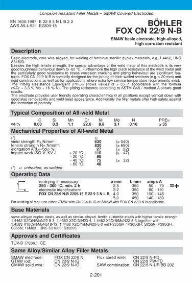
DescriptionBasic electrode, core wire alloyed, for welding of ferritic-austenitic duplex materials, e.g. 1.4462, UNSS31803. Besides the high tensile strength, the special advantage of the weld metal of this electrode is its verygood toughness behaviour down to -60 °C. Furthermore the high crack resistance of the weld metal andthe particularly good resistance to stress corrosion cracking and pitting behaviour are significant fea-tures. FOX CN 22/9 N-B is specially designed for the joining of thick-walled sections (e.g. > 20 mm) andrigid constructions as well as for applications where extra low service temperature requirements exist.The Pitting Resistance Equivalent (PREN) shows values of ≥ 35 in accordance with the formula(%Cr + 3.3 % Mo + 16 % N). The pitting resistance according to ASTM G48 / method A shows goodresults.The electrode provides user friendly operating characteristics in all positions except vertical down withgood slag removability and weld bead appearance. Additionally the filler metals offer high safety againstthe formation of porosity.
Approvals and CertificatesTÜV-D (7084.), CE
Base Materialssame-alloyed duplex steels, as well as similar-alloyed, ferritic-austenitic steels with higher tensile strength1.4462 X2CrNiMoN22-5-3, 1.4362 X2CrNiN23-4, 1.4462 X2CrNiMoN22-5-3 together with 1.4583 X10CrNiMoNb18-12, 1.4462 X2CrNiMoN22-5-3 mit P235GH / P265GH, S255N, P295GH,S355N, 16Mo3 UNS S31803, S32205
Operating Datare-drying if necessary: ø mm L mm amps A250 - 300 °C, min. 2 h 2.5 350 50 - 375electrode identification: 3.2 350 80 - 110FOX CN 22/9 N-B 2209-15 E 22 9 3 N L B 4.0 350 100 - 145
5.0 450 140 - 180For welding of root runs either GTAW with CN 22/9 N-IG or SMAW with FOX CN 22/9 N is applicable.
Mechanical Properties of All-weld Metal(*) uyield strength Re N/mm2: 630 (≥ 540)tensile strength Rm N/mm2: 830 (≥ 690)elongation A (L0=5d0) %: 27 (≥ 322)impact work ISO-V KV J + 20 °C: 110 (≥ 347)
- 20 °C: 90- 40 °C: 75 (≥ 332)- 60 °C: 40
(*) u untreated, as-welded
Typical Composition of All-weld MetalC Si Mn Cr Ni Mo N PREN
wt-% 0.03 0.3 1.1 22.6 8.8 3.1 0.16 ≥ 35
EN 1600:1997: E 22 9 3 N L B 2 2AWS A5.4-92: E2209-15 BÖHLER
FOX CN 22/9 N-BSMAW basic electrode, high-alloyed,
high corrosion resistant
2-201
Same Alloy/Similar Alloy Filler MetalsSMAW electrode: FOX CN 22/9 N Flux cored wire: CN 22/9 N-FDGTAW rod: CN 22/9 N-IG CN 22/9 PW-FDGMAW solid wire: CN 22/9 N-IG SAW combination: CN 22/9 N-UP/BB 202
Corrosion Resistant Filler Metals – SMAW Covered Electrodes

DescriptionRutile electrode, designed for ferritic-austenitic duplex steels, e.g. 1. 4462, UNS 31803. Field of applications arein off-shore engineering and in the chemical industry. Besides offering high mechanical strength and toughness,the weld metal is also noted for excellent resistance to stress corrosion cracking and pitting resistance. BÖHLERFOX CN 22/9 N offers excellent positional weldability, and thus is perfectly suited for pipe welding. Besides thegood wetting characteristics, slag removability, resistance to porosity and reliable CVN toughness down to -20 °C it is designed with a fully alloyed core wire providing best corrosion resistance and a very homogeneousmicro structure with specified ferrite contents of 30 – 60 FN (WRC) and a Pitting Resistance Equivalent (PREN)of > 35. For wall thicknesses above 20 mm or impact requirements down to -60 °C we recommend our basic coated electrode BÖHLER FOX CN 22/9 N-B.
Approvals and CertificatesTÜV-D (3636.), TÜV-A (260), ABS (E 22 09-17), DNV (Duplex), GL (4462), LR (X), RINA (2209), Statoil, SEPROZ, CE
Base Materialssame-alloyed duplex steels, as well as similar-alloyed, ferritic-austenitic steels with highertensile strength
1.4462 X2CrNiMoN22-5-3, 1.4362 X2CrNiN23-4,1.4462 X2CrNiMoN22-5-3 mit 1.4583 X10CrNiMoNb18-12, 1.4462 X2CrNiMoN22-5-3together with P235GH / P265GH, S255N, P295GH, S355N, 16Mo3
UNS S31803, S32205
Operating Datare-drying if necessary: ø mm L mm amps A250 - 300 °C, min. 2 h 2.5 350 40 - 375electrode identification: 3.2 350 70 - 120FOX CN 22/9 N 2209-17 E 22 9 3 N L R 4.0 350 110 - 160
5.0 450 150 - 200Preheating and interpass temperature max. +150 °C. In case of solution annealing is carried out max. +250 °C. Heat input in according to wall thickness.
Mechanical Properties of All-weld Metal(*) uyield strength Re N/mm2: 650 (≥ 540)tensile strength Rm N/mm2: 820 (≥ 690)elongation A (L0 = 5d0) %: 25 (≥ 322)impact work ISO-V KV J + 20 °C: 55 (≥ 347)
- 10 °C: 50- 20 °C: (≥ 332)
(*) u untreated, as-welded
Typical Composition of All-weld MetalC Si Mn Cr Ni Mo N PREN
wt-% 0.03 0.8 0.9 22.6 9.0 3.1 0.17 ≥ 35
EN 1600:1997: E 22 9 3 N L R 3 2AWS A5.4-92: E2209-17 BÖHLER FOX CN 22/9 N
SMAW rutile electrode, high-alloyed, high corrosion resistant
2-202
Same Alloy/Similar Alloy Filler MetalsSMAW electrode: FOX CN 22/9 N-B Flux cored wire: CN 22/9 N-FDGTAW rod: CN 22/9 N-IG CN 22/9 PW-FDGMAW solid wire: CN 22/9 N-IG SAW combination: CN 22/9 N-UP/BB 202
Corrosion Resistant Filler Metals – SMAW Covered Electrodes

2-203
DescriptionBasic electrode, for welding of ferritic-austenitic superduplex steels. By virtue of specific alloycomposition the deposit has, in addition to high tensile strength and toughness, also excellentresistance to stress corrosion cracking and pitting corrosion. The operating temperature rangeis -50 °C up to +250 °C. Well suited for the conditions in the offshore field.
Approvals and Certificates–
Same Alloy Filler MetalsGTAW rod: CN 25/9 CuT-IGGMAW solid wire: CN 25/9 CuT-IG
Base Materials25% Cr-Superduplex steels e.g.1.4501 X2CrNiMoCuWN 25-7-4UNS S 32750, UNS S32760, ZERON 100, SAF 25/07, FALC 100
Operating Datare-drying if necessary: ø mm L mm amps A250-300°C, min. 2 h 2.5 300 55-80electrode identification: 3.2 350 80-105FOX CN 25/9 Cu T E 25 9 4 N L B 4.0 350 90-140
Welding of root pass with „thick layer“. Next two passes with thin layers and low heat input toavoid overheating and precipitations
Mechanical Properties of All-weld Metal(*) uyield strength Re N/mm2: 650 (≥ 600)tensile strength Rm N/mm2: 850 (≥ 750)elongation A (L0=5d0) %: 25 (≥ 22)impact work ISO-V KV J +20 °C: 75 (≥ 70)
-50 °C: 50 (≥ 34)
(*) u untreated, as welded
Typical Composition of All-weld MetalC Si Mn Cr Ni Mo N Cu T PREN
wt-% 0.03 0.5 1.0 25.0 9.5 3.7 0.22 0.7 0.7 ≥40
EN 1600:1997: E 25 9 4 N L B 2 2AWS A5.9-93: E2553-15 (mod.) BÖHLER
FOX CN 25/9 CuTSMAW basic electrode
high alloyed, highly corrosion resistant
Corrosion Resistant Filler Metals – SMAW Covered Electrodes
2-204
Notes

DescriptionGTAW rod of low-carbon type 13 % Cr 4 % Ni suited for soft-martensitic steels like 1.4313 / CA6 NM. Designed with precisely tuned alloying composition creating a weld deposit featuringvery good ductility, CVN toughness and crack resistance despite its high strength.BÖHLER CN 13/4-IG as well as the coated electrode BÖHLER FOX CN 13/4 and the analogous GMAW wire are very popular in the construction of hydro turbines.
Approvals and CertificatesTÜV-D (04110.), SEPROZ, CE
Base Materials1.4317 GX4CrNi13-4, 1.4313 X3CrNiMo13-4, 1.4351 X3CrNi13-4, 1.4414 GX4CrNiMo13-4
ACI Gr. CA6NM
Operating Datashielding gases: 100 % Argon ø mmrod marking: 2.0
front: W 13 4 2.4back: -
Preheating and interpass temperatures in case of thick-walled sections 100 - 160 °C. Maximumheat input 15 kJ/cm. Tempering at 580 - 620 °C.
Typical Composition of Welding RodC Si Mn Cr Ni Mo
wt-% 0.01 0.7 0.7 12.3 4.7 0.5
EN 12072:1999: W 13 4AWS A5.9-93: ER410 NiMo (mod.)W.Nr.: 1.4351 (mod.)
BÖHLER CN 13/4-IGGTAW rod, high-alloyed,
stainless
2-205
Mechanical Properties of All-weld Metal(*) u ayield strength Re N/mm2: 915 (≥ 780) 750 (≥ 720)tensile strength Rm N/mm2: 1000 (≥ 950) 830 (≥ 800)elongation A (L0=5d0) %: 15 (≥ 310) 21 (≥ 18)impact work ISO-V KV J + 20 °C: 85 (≥ 380) 150 (≥ 50)
- 60 °C: (≥ 32)(*) u untreated, as-welded – shielding gas Argon
a annealed, 600 °C/8 h/furnace down to 300 °C/air – shielding gas Argon
Same Alloy Filler Metals SMAW electrode: FOX CN 13/4 GMAW solid wire: CN 13/4-IG
FOX CN 13/4 SUPRA Metal cored wire: CN 13/4-MCCN 13/4-MC (F)
SAW combination: CN 13/4-UP/BB 203
Corrosion Resistant Filler Metals – GTAW Rods

DescriptionGTAW rod of type W 19 9 L / ER308L suitable not only for standard welding jobs but also forcryogenic applications down to -269 °C.Good welding and wetting characteristics of BÖHLER EAS 2-IG as well as corrosion resistanceup to +350 °C is achieved.
Approvals and CertificatesTÜV-D (0145.), DB (43.014.08), ÖBB, TÜV-A (97), DNV (308L), GL (4550), SEPROZ, CE
Base Materials1.4306 X2CrNi19-11, 1.4301 X5CrNi18-10, 1.4311 X2CrNiN18-10, 1.4312 GX10CrNi18-8,1.4541 X6CrNiTi18-10, 1.4546 X5CrNiNb18-10, 1.4550 X6CrNiNb18-10
AISI 304, 304L, 304LN, 302, 321, 347; ASTM A157 Gr. C9; A320 Gr. B8C or D
Operating Datashielding gases: 100 % Argon ø mmrod marking: 1.6
front: W 19 9 L 2.0back: ER 308 L 2.4
3.0
Typical Composition of Welding RodC Si Mn Cr Ni
wt-% ≤0.02 0.45 1.8 20.0 10.0
EN 12072:1999: W 19 9 LAWS A5.9-93: ER308LW.Nr.: 1.4316
BÖHLER EAS 2-IGGTAW rod, high-alloyed,
chemical resistant
2-206
Same Alloy / Similar Alloy Filler Metals SMAW electrode: FOX EAS 2 Metal cored wire: EAS 2-MC
FOX EAS 2-A GMAW flux cored wire: EAS 2-FDFOX EAS 2-VD EAS 2 PW-FD
GMAW solid wire: EAS 2-IG (Si) EAS 2 PW-FD (LF)SAW combination: EAS 2-UP/BB 202
Mechanical Properties of All-weld Metal(*) uyield strength Re N/mm2: 450 (≥ 400)tensile strength Rm N/mm2: 620 (≥ 570)elongation A (L0 = 5d0) %: 38 (≥ 335)impact work ISO-V KV J + 20 °C: 150 (≥ 100)
- 269 °C: 75 (≥ 335)(*) u untreated, as-welded – shielding gas Argon
Corrosion Resistant Filler Metals – GTAW Rods

DescriptionGTAW rod of type W 19 9 Nb / ER 347 engineered to a very precise analysis to create a welddeposit of high purity, superior hot cracking an corrosion resistance.CVN toughness down to -196 °C, resistant to intergranular corrosion up to +400 °C.
Approvals and CertificatesTÜV-D (0142.), TÜV-A (77), GL (4550), LTSS, SEPROZ, CE
Base Materials1.4550 X6CrNiNb18-10, 1.4541 X6CrNiTi18-10, 1.4552 GX5CrNiNb19-11, 1.4301 X5CrNi18-10, 1.4312 GX10CrNi18-8, 1.4546 X5CrNiNb18-10, 1.4311 X2CrNiN18-10, 1.4306 X2CrNi19-11
AISI 347, 321, 302, 304, 304L, 304LN; ASTM A296 Gr. CF 8 C; A157 Gr. C9; A320 Gr. B8C or D
Operating Datashielding gases: 100 % Argon ø mmrod marking: 1.6
front: W 19 9 Nb 2.0back: ER 347 2.4
3.0
Typical Composition of Welding RodC Si Mn Cr Ni Nb
wt-% 0.05 0.5 1.8 19.6 9.5 +
EN 12072:1999: W 19 9 NbAWS A5.9-93: ER 347W.Nr.: 1.4551
BÖHLER SAS 2-IGGTAW rod, high-alloyed,
chemical resistant
2-207
Same Alloy Filler Metals SMAW electrode: FOX SAS 2 GMAW solid wire: SAS 2-IG (Si)
FOX SAS 2-A GMAW flux cored wire: SAS 2-FDSAS 2 PW-FD
SAW combination: SAS 2-UP/BB 202
Mechanical Properties of All-weld Metal(*) uyield strength Re N/mm2: 490 (≥ 450)tensile strength Rm N/mm2: 660 (≥ 600)elongation A (L0 = 5d0) %: 35 (≥ 330)impact work ISO-V KV J + 20 °C: 140 (≥ 100)
- 196 °C: (≥ 332)(*) u untreated, as-welded – shielding gas Argon
Corrosion Resistant Filler Metals – GTAW Rods

DescriptionGTAW rod of type W 19 12 3 L / ER316L engineered to a very precise analysis to create a welddeposit of high purity, superior hot cracking an corrosion resistance.CVN toughness down to -196 °C, resistant to intergranular corrosion up to +400 °C.
Approvals and CertificatesTÜV-D (0149.), DB (43.014.12), ÖBB, TÜV-A (101), DNV (316L), GL (4429), SEPROZ, CE
Base Materials1.4401 X5CrNiMo17-12-2, 1.4404 X2CrNiMo17-12-2, 1.4435 X2CrNiMo18-14-3,1.4436 X3CrNiMo17-13-3, 1.4571 X6CrNiMoTi17-12-2, 1.4580 X6CrNiMoNb17-12-2,1.4583 X10CrNiMoNb18-12, 1.4409 GX2CrNiMo 19-11-2
S31653, AISI 316L, 316Ti, 316Cb
Operating Datashielding gases: 100 % Argon ø mmrod marking: 1.6
front: W 19 12 3 L 2.0back: ER 316 L 2.4
3.0
Typical Composition of Welding RodC Si Mn Cr Ni Mo
wt-% ≤0.02 0.5 1.8 18.5 12.3 2.8
EN 12072:1999: W 19 12 3 LAWS A5.9-93: ER316LW.Nr.: 1.4430
BÖHLER EAS 4 M-IGGTAW rod, high-alloyed,
chemical resistant
2-208
Same Alloy Filler Metals SMAW electrode: FOX EAS 4 M Metal cored wire: EAS 4 M-MC
FOX EAS 4 M (LF) GMAW flux cored wire: EAS 4 M-FDFOX EAS 4 M-A EAS 4 PW-FDFOX EAS 4 M-VD EAS 4 PW-FD (LF)FOX EAS 4 M-TS SAW combination: EAS 4 M-UP/BB 202
GMAW solid wire: EAS 4 M-IG (Si)
Mechanical Properties of All-weld Metal(*) uyield strength Re N/mm2: 470 (≥ 450)tensile strength Rm N/mm2: 650 (≥ 580)elongation A (L0 = 5d0) %: 38 (≥ 330)impact work ISO-V KV J + 20 °C: 140 (≥ 100)
- 196 °C: (≥ 332)(*) u untreated, as-welded – shielding gas Argon
Corrosion Resistant Filler Metals – GTAW Rods
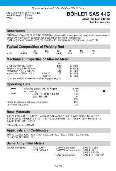
DescriptionGTAW rod of type W 19 12 3 Nb / ER318 engineered to a very precise analysis to create a welddeposit of high purity, superior hot cracking an corrosion resistance.CVN toughness down to -120 °C, resistant to intergranular corrosion up to +400 °C.
Approvals and CertificatesTÜV-D (0236.), KTA 1408.1 (8046.00), DB (43.014.03), ÖBB, TÜV-A (134), GL (4571), SEPROZ, CE
Base Materials1.4571 X6CrNiMoTi17-12-2, 1.4580 X6CrNiMoNb17-12-2, 1.4401 X5CrNiMo17-12-2,1.4581 GX5CrNiMoNb19-11-2, 1.4437 GX6CrNiMo18-12, 1.4583 X10CrNiMoNb18-12,1.4436 X3CrNiMo17-13-3
AISI 316L, 316Ti, 316Cb
Operating Datashielding gases: 100 % Argon ø mmrod marking: 1.0*
front: W 19 12 3 Nb 1.2*back: ER 318 1.6
2.0* these diameters are delivered with a higher 2.4
Si-content (ca. 0.8 %) 3.0
Typical Composition of Welding RodC Si Mn Cr Ni Mo Nb
wt-% 0.035 0.45 1.7 19.5 11.4 2.7 +
EN 12072:1999: W 19 12 3 NbAWS A5.9-93: ER318W.Nr.: 1.4576
BÖHLER SAS 4-IGGTAW rod, high-alloyed,
chemical resistant
2-209
Same Alloy Filler Metals SMAW electrode: FOX SAS 4 GMAW solid wire: SAS 4-IG (Si)
FOX SAS 4-A GMAW flux cored wire: SAS 4-FDSAS 4 PW-FD
SAW combination: SAS 4-UP /BB 202
Mechanical Properties of All-weld Metal(*) uyield strength Re N/mm2: 520 (≥ 400)tensile strength Rm N/mm2: 700 (≥ 600)elongation A (L0 = 5d0) %: 35 (≥ 330)impact work ISO-V KV J + 20 °C: 120 (≥ 100)
- 120 °C: (≥ 332)(*) u untreated, as-welded – shielding gas Argon
Corrosion Resistant Filler Metals – GTAW Rods

DescriptionGTAW rod designed for joint welding of the special stainless steel grade X2CrNiSi18-15, mat-no. 1.4361 (BÖHLER A 610), which is resistant to the attack of highly concentrated nitric acidand of nitric acid additionally containing strong deoxidants. Also suited for cladding applicationson analogous materials. Operating temperatures up to +350 °C.
Approvals and CertificatesTÜV-D (1483.), CE
Base Materials1.4361 X1CrNiSi18-15-4, UNS S30600
Operating Datashielding gases: 100 % Argon ø mmrod marking: 1.6
front: W Z 19 13 Si NL 2.0back: 1.4361 2.4
The deposit does not require post weld heat treatment. In exceptional cases quenching froma temperature of +1100 °C in water is recommended. Keep heat input as low as possible.Interpass temperature should not to exceed +150 °C. If possible, water cooling to improveheat dissipation is recommended.
Typical Composition of Welding RodC Si Mn Cr Ni N
wt-% ≤ 0.012 4.6 0.7 19.5 13.4 0.12
EN 12072:1999: W Z19 13 Si NLW.-Nr.: 1.4361 BÖHLER EASN 2 Si-IG
GTAW rod, high-alloyed, highly corrosion resistant
2-210
Same Alloy Filler Metals SMAW electrode: FOX EAS 2 Si
Mechanical Properties of All-weld Metal(*) uyield strength Re N/mm2: 520 (≥ 440)tensile strength Rm N/mm2: 750 (≥ 700)elongation A (L0 = 5d0) %: 35 (≥ 325)impact work ISO-V KV J + 20 °C: 100 (≥ 340)
- 50 °C: (≥ 332)(*) u untreated, as-welded – shielding gas Argon
Corrosion Resistant Filler Metals – GTAW Rods

DescriptionGTAW rod for 3-4 % molybdenum alloyed CrNi-steels like 1.4438 / 317L.The weld metal shows a stable austenitic microstructure with good pitting resistance (PREN
>35) and crevice corrosion resistance as well as excellent CVN toughness behaviour down to-269 °C. Resistant to intergranular corrosion up to +400 °C.BÖHLER ASN 5-IG has an increased Mo content (4.1 %) to compensate for segregation whenwelding high molybdenum alloyed steels, thus producing equivalent corrosion resistance to therelevant base metals offering a 3-4 % Mo guarantee.
Approvals and CertificatesTÜV-D (00017.), TÜV-A (463), DNV (X), SEPROZ, CE
Base Materials1.4436 X3CrNiMo17-13-3, 1.4439 X2CrNiMoN17-13-5, 1.4429 X2CrNiMoN17-13-3,1.4438 X2CrNiMo18-15-4, 1.4583 X10CrNiMoNb18-12
AISI 316Cb, 316LN, 317LN, 317L; UNS S31726
Operating Datashielding gases: 100 % Argon ø mmrod marking: 1.6
front: W Z 18 16 5 NL 2.0back: 1.4453 2.4
Typical Composition of Welding RodC Si Mn Cr Ni Mo N PREN FN
wt-% ≤0.02 0.4 5.5 19.0 17.2 4.3 0.16 38.0 ≤ 0.5
EN 12072:1999: W Z18 16 5 NLAWS A5.9-93: ER317LN (mod.)W.Nr.: 1.4453
BÖHLER ASN 5-IGGTAW rod, high-alloyed,
highly corrosion resistant
2-211
Same Alloy/Similar Alloy Filler Metals SMAW electrode: FOX ASN 5 GMAW flux cored wire: E 317L-FD*
FOX ASN 5-A E 317L PW-FD*GMAW solid wire: ASN 5-IG (Si) SAW combination: ASN 5-UP/BB 203
* for similar alloyed base metals only, not fully austenitic.
Mechanical Properties of All-weld Metal(*) uyield strength Re N/mm2: 440 (≥ 400)tensile strength Rm N/mm2: 650 (≥ 600)elongation A (L0 = 5d0) %: 35 (≥ 330)impact work ISO-V KV J + 20 °C: 120 (≥ 370)
- 269 °C: 75 (≥ 332)(*) u untreated, as-welded – shielding gas Argon
Corrosion Resistant Filler Metals – GTAW Rods

DescriptionGTAW rod, N-alloyed, fully austenitic and nonmagnetic, special distinguished by its especiallyhigh resistance to pitting, crevice corrosion and stress corrosion cracking. Excellent cryogenictoughness. Suitable for service temperatures up to +350 °C, and up to +400 °C in media that do not induceintergranular corrosion. Used for sea water desalinisation plants, centrifuges, bleaching plantsand in special shipbuilding.
Approvals and CertificatesWIWEB, GL (3954), CE
Base Materials1.3948 X4CrNiMnMoN19-13-8, 1.3951 X2CrNiMoN22-15, 1.3952 X2CrNiMoN18-14-3,1.3964 X2CrNiMnMoNNb21-16-5-3, 1.4439 X2CrNiMoN17-13-5
Operating Datashielding gases: 100 % Argon ø mmrod marking: 2.0
front: W Z 22 17 8 4 NLback: 1.3954
Preheating of the base metal is not required. The interpass temperature should not exceed +150 °C.
Typical Composition of Welding RodC Si Mn Cr Ni Mo N PREN
wt-% 0.02 0.65 7.5 22.2 18.0 3.7 0.23 36.9
EN 12072:1999: W Z22 17 8 4 NLW.Nr.: 1.3954 BÖHLER AM 400-IG
GTAW rod, high-alloyed, highly corrosion resistant
2-212
Same Alloy Filler Metals SMAW electrode: FOX AM 400 GMAW solid wire: AM 400-IG
Mechanical Properties of All-weld Metal(*) uyield strength Re N/mm2: 480 (≥ 450)tensile strength Rm N/mm2: 700 (≥ 680)elongation A (L0 = 5d0) %: 35 (≥ 330)impact work ISO-V KV J + 20 °C: 170 (≥ 370)
- 196 °C: (≥ 332)(*) u untreated, as-welded – shielding gas Argon
Corrosion Resistant Filler Metals – GTAW Rods

2-213
DescriptionGTAW rod for joining and surfacing applications on matching/similar steels. For weld claddingon high temperature steels and for fabrication joints on claddings. Characterised by a low C-content, a limited Mo-content (for better Huey-test-resistance), a well-defined N-alloying as wellas a high Ni-content to assure a fully austenitic structure (ferrite contents < 0.5 %). The corro-sion rates in the Huey-test are max. 0.25 g/m2.h (10.89 mils/year). it is suited for urea plantcomponents exposed to extremely severe corrosion at high pressures and temperatures. Theweld deposit will exhibit superior resistance to boiling concentrated nitric acid (optimum condi-tion: 60-80 % HNO3) when made to join components of the highest Huey test quality. It is alsorecommendable for weldments wetted by strong chloride solutions at high temperatures. Thechromium and molybdenum percentages create good resistance to pitting from solutions con-taining chlorine ions. Further applications involve severe corrosive service in such industries asdyeing (leaching and dyeing baths), textiles, paper, leather, chemicals, pharmaceuticals, andrayon. Resistant to intercrystalline corrosion and wet corrosion up to +350 °C. During weldingan interpass temperature of 150 °C should be avoided.
Approvals and CertificatesTÜV-D (09750.), CE
Same Alloy Filler MetalsSMAW electrode: FOX EASN 25M
Base MaterialsX2CrNiMoN25-22-2 (1.4466) and in combination withX1CrNiMoN25-25-2 (1.4465), X2CrNiMo18-14-3 (1.4435)
Operating Datashielding gases: ø mm100% Argon 1.6rod marking: 2.0front: 1.4465 2.4back: W 25 22 2 NL
Mechanical Properties of All-weld Metal(*) Uyield strength Re N/mm2: >400tensile strength Rm N/mm2: >600elongation A (L0=5d0) %: >30impact work ISO-V KV J +20 °C >80
(*) u untreated, as-welded – shielding gas Argon
Typical Composition of Welding RodC Si Mn Cr Ni Mo N
wt-% 0.014 0.1 6.0 25 22.5 2.2 0.12
EN 12072:1999: W 25 22 2 NL BÖHLER EASN 25 M-IG GTAW rod
high-alloyed, chemical resistant
Corrosion Resistant Filler Metals – GTAW Rods

DescriptionGTAW rod for corrosion resistant 4-5% Mo-alloyed CrNi-steels like 1.4539 / 904L. Very high pitting resistantequivalent (PREN ≥ 45) – pitting potential (%Cr + 3.3 x %Mo + 30 x %N). Due to the high Mo content (6.2%) in comparison to W-No. 1.4539 respectively UNS N08904, the high segregation rate of high Mo-alloyedCrNi-weld metal can be compensated. The fully austenitic weld metal possess a marked resistance towards pitting and crevice corrosion in chlori-de containing media. Highly resistant against sulphur-, phosphorus-, acetic- and formic acid, as well as sea-and brackish water. Caused from the low C-content of the weld metal, the risk of intergranular corrosion canbe avoided. The high Ni-content in comparison to standard CrNi-weld metals leads to high resistanceagainst stress corrosion cracking. Special applicable in sulphur- and phosphorus production, pulp and paper industry, flue gas desulphurisa-tion plants, further on for fertilizer production, petrochemical industry, fatty-, acetic- and formic acid produc-tion, sea water sludge fittings and pickling plants which are proceeded with sea or brackish water.
Approvals and CertificatesTÜV-D (4881.), TÜV-A (390), Statoil, CE
Base Materialssame-alloyed high-Mo Cr-Ni-steels1.4539 X1NiCrMoCu25-20-5, 1.4439 X2CrNiMoN17-13-5, 1.4537 X1CrNiMoCuN25-25-5UNS N08904, S31726
Operating Datashielding gases: 100 % Argon ø mmrod marking: 1.6
front: W Z 20 25 5 Cu NL 2.0back: ER 385 2.4
Preheating and post weld heat treatment is not required by the weld deposit. Interpass temperature shouldnot exceed +150 °C.
Typical Composition of Welding RodC Si Mn Cr Ni Mo Cu N PREN
wt-% ≤ 0.02 0.7 4.7 20.0 25.4 6.2 1.5 0.12 ≥ 45.0
EN 12072:1999: W Z20 25 5 Cu NLAWS A5.9-93: ER385 (mod.)W.Nr.: 1.4519 (mod.)
BÖHLER CN 20/25 M-IG GTAW rod, high-alloyed,
highly corrosion resistant
2-214
Same Alloy Filler Metals SMAW electrode: FOX CN 20/25 M GMAW solid wire: CN 20/25 M-IG (Si)
FOX CN 20/25 M-A
Mechanical Properties of All-weld Metal(*) uyield strength Re N/mm2: 440 (≥ 350)tensile strength Rm N/mm2: 670 (≥ 600)elongation A (L0 = 5d0) %: 42 (≥ 330)impact work ISO-V KV J + 20 °C: 115 (≥ 380)
- 269 °C: 72 (≥ 332)(*) u untreated, as-welded – shielding gas Argon
Corrosion Resistant Filler Metals – GTAW Rods

DescriptionGTAW rod of type W 22 9 3 NL / ER2209 designed for welding ferritic-austenitic duplex steels like1.4462 / UNS 31803. The deposit possess, in addition to high tensile strength and toughness, alsoexcellent resistance to stress corrosion cracking and pitting (Huey-test ASTM A 262-79 practice C). Theoperating temperature range is -60 °C up to +250 °C. To ensure particularly good weld metal propertiescare must be taken to archive controlled dilution and thorough back purging. In case of severe corrosionrequirement, small amounts of N2 can be added to the shielding respectively purging gas. BÖHLER CN 22/9 N-IG is characterised by a precisely alloyed composition which includes an extremelylow oxygen content. It offers very high quality standards for ease of operation and good mechanical pro-perties.
Approvals and CertificatesTÜV-D (4484.), TÜV-A (423), DNV (X{I1}), Statoil, GL (4462), ABS (ER 2209), LR (X), CE
Base Materialssame-alloyed duplex steels, as well as similar-alloyed, ferritic-austenitic steels with highertensile strength1.4462 X2CrNiMoN22-5-3, 1.4362 X2CrNiN23-4,1.4462 X2CrNiMoN22-5-3 with 1.4583 X10CrNiMoNb18-12,1.4462 X2CrNiMoN22-5-3 with P235GH/ P265GH, S255N, P295GH, S355N, 16Mo3UNS S31803, S32205
Operating Datashielding gases: 100 % Argon ø mm
Ar + 1-2 % N2 1.6rod marking: 2.0
front: W 22 9 3 NL 2.4back: ER 2209 3.2
Preheat and post weld heat treatment is generally not required. Interpass temperature should notexceed +150 °C.
Typical Composition of Welding RodC Si Mn Cr Ni Mo N PREN
wt-% ≤ 0.015 0.4 1.7 22.5 8.8 3.2 0.15 ≥ 35
EN 12072:1999: W 22 9 3 NLAWS A5.9-93: ER2209W.Nr.: 1.4462 (mod.)
BÖHLER CN 22/9 N-IGGTAW rod, high-alloyed,
highly corrosion resistant
2-215
Same Alloy Filler Metals SMAW electrode: FOX CN 22/9 N-B GMAW flux cored wire: CN 22/9 N-FD
FOX CN 22/9 N CN 22/9 PW-FDGMAW solid wire: CN 22/9 N-IG SAW combination: CN 22/9 N-UP/BB 202
Mechanical Properties of All-weld Metal(*) uyield strength Re N/mm2: 600 (≥ 560)tensile strength Rm N/mm2: 800 (≥ 720)elongation A (L0 = 5d0) %: 33 (≥ 325)impact work ISO-V KV J + 20 °C: 150 (≥ 100)
- 60 °C: (≥ 332)(*) u untreated, as-welded – shielding gas Argon
Corrosion Resistant Filler Metals – GTAW Rods

2-216
DescriptionGTAW-rod highly suitable for welding ferritic-austenitic superduplex steels. By virtue of specificalloy composition the deposit has, in addition to high tensile strength and toughness, alsoexcellent resistance to stress corrosion cracking and pitting corrosion. The operating tempera-ture range is -50 °C up to +250 °C. Well suited for the conditions in the offshore field. For appli-cations requiring low Hydrogen, we offer the product BÖHLER CN 25/9 CuT-IG-LH withHydrogen Content guaranteed less than 3 ppm.
Approvals and Certificates–
Same Alloy Filler MetalsStick electrode: FOX CN 25/9 CuTGMAW solid wire: CN 25/9 CuT-IG
Base Materials25 % Cr-Superduplex steels e.g.1.4501 X2CrNiMoCuWN 25-7-4UNS S 32750, S 32760 ZERON 100, SAF 25/07, FALC 100
Operating Datashielding gas: ø mmArgon + 2-3 % N2 2.0Argon 2.4rod marking:front: W 25 9 4 NLWelding of root pass with „thick layer“. Next two passes with thin layers and low heat input to avoid overheating and precipitations
Mechanical Properties of All-weld Metal(*) uyield strength Re N/mm2: ≥ 700tensile strength Rm N/mm2: ≥ 850elongation A (L0=5d0) %: ≥ 25impact work ISO-V AV J +20 °C: ≥ 120
-40 °C: ≥ 100-50 °C: 50
(*) u untreated, as welded – shielding gas Argon
Typical Composition of Welding RodC Si Mn Cr Ni Mo N Cu T PREN
wt-% 0.02 0.3 0.7 25.2 9.2 3.6 0.22 0.6 0.62 ≥40
EN 12072:1999: W 25 9 4 NLAWS A5.9-93: ER2553 (mod.) BÖHLER
CN 25/9 CuT-IGGTAW-rod
high alloyed, highly corrosion resistant
Corrosion Resistant Filler Metals – GTAW Rods

2-217
DescriptionGMAW solid wire for catalytic converters as well as exhaust silencers, mufflers, manifolds, andmanifold elbows of analogous or similar materials. Also used for repair welding and sur-facing of sealing faces of gas, water, and steam turbines with service temperatures of up to +450 °C. Resists scaling up to +900 °C. Machinability depends largely on the degree of basemetal dilution. Outstanding feeding, very good welding and flow characteristics.
Approvals and CertificatesSEPROZ
Same Alloy Filler Metals–
Base Materialsanalogous or similar alloyed steels e.g.1.4512 X2CrTi12, 1.4006 X10Cr13, 1.4024 X15Cr13, 1.4021 X20Cr13AISI 409, 410, 420
Operating DataShielding gas: ø mmArgon +8-10 % CO2 1.0
Mechanical Properties of All-weld Metal(*) u aBrinell-hardness HB: 150 130
(*) u untreated, as-welded – shielding gas Ar +8-10 % CO2
a annealed, 750 °C/2h – shielding gas Ar +8-10 % CO2
Typical Composition of Solid WireC Si Mn Cr Nb
wt-% 0.04 0.6 0.6 11.5 +
EN 12072:1999: G Z13 Nb LAWS A5.9-93: ER409Cb BÖHLER KW 5 Nb-IG
GMAW solid wirehigh-alloyed, stainless
Corrosion Resistant Filler Metals – GMAW Solid Wires

2-218
DescriptionGMAW solid wire for catalytic converters as well as exhaust silencers, mufflers, manifolds, andmanifold elbows of analogous or similar materials. Resists scaling up to +900 °C. Outstandingfeeding characteristics. Very good welding and flow characteristics.
Approvals and Certificates–
Base Materials1.4511 X3CrNb17, 1.4016 X6Cr17, AISI 430
Operating DataShielding gas: ø mmArgon +5-10 % CO2 1.0Argon +1-3 % O2
Mechanical Properties of All-weld Metal(*) u aBrinell-hardness HB: 150 130
(*) u untreated, as welded – shielding gas Ar +8-10 % CO2
a annealed, 760 °C/2h – shielding gas Ar +8-10 % CO2
Typical Composition of Solid WireC Si Mn Cr Nb
wt-% 0.02 0.5 0.5 18.0 >12xC
EN 12072:1999: G Z18 Nb LAWS A5.9-93: ER430 (mod.) BÖHLER
CAT 430 L Cb-IGGMAW solid wire
high alloyed, stainless
Corrosion Resistant Filler Metals – GMAW Solid Wires

2-219
DescriptionGMAW solid wire for catalytic converters as well as exhaust silencers, mufflers, manifolds, andmanifold elbows of analogous or similar materials. Resists scaling up to +900 °C. Outstandingfeeding characteristics. Very good welding and flow characteristics
Base Materials1.4510, X3CrTi17, 1.4016 X6Cr17, 1.4502, X8CrTi18AISI 439
Operating DataShielding gas: ø mmArgon +5-10 % CO2 1.0Argon +1-3 % O2
Mechanical Properties of All-weld Metal(*) u ayield strength Re N/mm2:tensile strength Rm N/mm2:elongation A (L0=5d0) %:impact work ISO-V KV JBrinell-hardness HB 150 130
(*) u untreated, as welded – shielding gas Ar +8-10 % CO2
a annealed, 800 °C/1h – shielding gas Ar +8-10 % CO2
Typical Composition of Solid WireC Si Mn Cr Ti
wt-% 0.03 0.8 0.8 18.0 >12xC
EN 12072:1999: G Z18 Ti LAWS A5.9-93: ER430 (mod.) BÖHLER
CAT 439 L Ti-IGGMAW solid wire, high alloyed, stainless
Corrosion Resistant Filler Metals – GMAW Solid Wires
Approvals and Certificates–

DescriptionGMAW solid wire of low-carbon type 13% Cr 4% Ni suited for soft-martensitic steels like 1.4313/ CA 6 NM. Designed with precisely tuned alloying composition creating a weld deposit featuring very good ductility, CVN toughness and crack resistance despite its high strength.BÖHLER CN 13/4-IG and the analogous GTAW rod as well as the coated electrode BÖHLERFOX CN 13/4 are very popular in the construction of hydro turbines.
Approvals and CertificatesTÜV-D (04110.), SEPROZ, CE
Base Materials1.4317 GX4CrNi13-4, 1.4313 X3CrNiMo13-4, 1.4351 X3CrNi13-4, 1.4414 GX4CrNiMo13-4
ACI Gr. CA 6 NM
Typical Composition of Solid WireC Si Mn Cr Ni Mo
wt-% 0.01 0.65 0.7 12.2 4.8 0.5
EN 12072:1999: G 13 4AWS A5.9-93: ER410NiMo (mod.) BÖHLER CN 13/4-IG
GMAW solid wire high-alloyed, stainless
2-220
Same Alloy Filler Metals SMAW electrode: FOX CN 13/4 GTAW rod: CN 13/4-IG
FOX CN 13/4 SUPRA Metal cored wire: CN 13/4-MCCN 13/4-MC (F)
SAW combination: CN 13/4-UP/BB 203
Mechanical Properties of All-weld Metal(*) u ayield strength Re N/mm2: 950 (≥ 750) 760 (≥ 680)tensile strength Rm N/mm2: 1210 (≥ 950) 890 (≥ 800)elongation A (L0 = 5d0) %: 12 (≥ 310) 17 (≥ 315)impact work ISO-V KV J + 20 °C: 36 (≥ 330) 80 (≥ 350)
- 20 °C: (≥ 347)(*) u untreated, as-welded – shielding gas Argon + 8 - 10 % CO2
a annealed, 580 °C/8 h furnace down to 300 °C/air – shielding gas Argon + 8 - 10 % CO2
Operating Datashielding gases: ø mmArgon + 8 - 10 % CO2 1.2
Preheating and interpass temperatures in case of thick-walled sections 100 - 160 °C.Maximum heat input 15 kJ/cm. Tempering at 580 - 620 °C.
Corrosion Resistant Filler Metals – GMAW Solid Wires
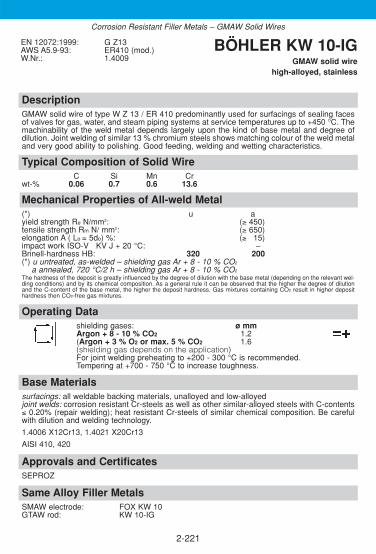
DescriptionGMAW solid wire of type W Z 13 / ER 410 predominantly used for surfacings of sealing facesof valves for gas, water, and steam piping systems at service temperatures up to +450 °C. Themachinability of the weld metal depends largely upon the kind of base metal and degree ofdilution. Joint welding of similar 13 % chromium steels shows matching colour of the weld metaland very good ability to polishing. Good feeding, welding and wetting characteristics.
Approvals and CertificatesSEPROZ
Base Materialssurfacings: all weldable backing materials, unalloyed and low-alloyedjoint welds: corrosion resistant Cr-steels as well as other similar-alloyed steels with C-contents≤ 0.20% (repair welding); heat resistant Cr-steels of similar chemical composition. Be carefulwith dilution and welding technology.
1.4006 X12Cr13, 1.4021 X20Cr13
AISI 410, 420
Typical Composition of Solid WireC Si Mn Cr
wt-% 0.06 0.7 0.6 13.6
EN 12072:1999: G Z13AWS A5.9-93: ER410 (mod.)W.Nr.: 1.4009
BÖHLER KW 10-IGGMAW solid wire
high-alloyed, stainless
2-221
Same Alloy Filler Metals SMAW electrode: FOX KW 10GTAW rod: KW 10-IG
Mechanical Properties of All-weld Metal(*) u ayield strength Re N/mm2: (≥ 450)tensile strength Rm N/ mm2: (≥ 650)elongation A ( Lo = 5do) %: (≥ 315)impact work ISO-V KV J + 20 °C: ––Brinell-hardness HB: 320 200(*) u untreated, as-welded – shielding gas Ar + 8 - 10 % CO2
a annealed, 720 °C/2 h – shielding gas Ar + 8 - 10 % CO2
The hardness of the deposit is greatly influenced by the degree of dilution with the base metal (depending on the relevant wel-ding conditions) and by its chemical composition. As a general rule it can be observed that the higher the degree of dilutionand the C-content of the base metal, the higher the deposit hardness. Gas mixtures containing CO2 result in higher deposithardness then CO2-free gas mixtures.
Operating Datashielding gases: ø mmArgon + 8 - 10 % CO2 1.2(Argon + 3 % O2 or max. 5 % CO2 1.6(shielding gas depends on the application)For joint welding preheating to +200 - 300 °C is recommended. Tempering at +700 - 750 °C to increase toughness.
Corrosion Resistant Filler Metals – GMAW Solid Wires

DescriptionGMAW solid wire of type G 17 / ER430 suitable for surfacing of sealing faces of gas, water andsteam valves and fittings. Service temperatures up to +450 °C. Scaling resistant up to +950 °C.Also in sulphur containing combustion gas at high temperature. BÖHLER KWA-IG wire is alsosuited for joint welding of stainless ferritic steels containing 12-17% chromium, and by the requestof colour matching weld deposit/base metal. For thick-walled components it is recommendable touse BÖHLER A 7-IG wire for the filler passes in order to improve the ductility behaviour of thejoint weld, KWA-IG wire for the cover pass especially in case of sulphur containing combustiongases. Excellent feeding, welding and wetting behaviour of the wire and weld metal are important economical features.
Approvals and CertificatesSEPROZ
Base Materialssurfacings: all weldable backing materials, unalloyed and low-alloyed.joint welds: corrosion resistant Cr-steels as well as other similar-alloyed steels with C-contentsup to 0.20 % (repair welding). Be careful with dilution and welding technology.1.4510 X3CrTi17AISI 430 Ti; AISI 431
Typical Composition of Solid WireC Si Mn Cr
wt-% 0.06 0.6 0.6 17.5
EN 12072:1999: G 17AWS A5.9-93: ER430 (mod.)W.Nr.: 1.4015
BÖHLER KWA-IGGMAW solid wire
high-alloyed, stainless
2-222
Same Alloy/Similar Alloy Filler Metals SMAW electrode: FOX SKWA GMAW solid wire: SKWA-IG
FOX SKWAM SKWAM-IG
Mechanical Properties of All-weld Metal(*) u u - 1. Layer u - 2. Layer u - 3. Layer ayield strength Re N/mm2: (≥ 340)tensile strength Rm N/mm2: (≥ 540)elongation A (Lo = 5do) %: (≥ 320)impact work ISO-V KV J + 20 °C –Brinell-hardness HB: 180-230 350-450 280-350 230-260 150)(*) u untreated, as-welded – base material mild steel – shielding gas Ar + 8 - 10 % CO2
a annealed, 800 °C/2 h – shielding gas Ar + 8 - 10 % CO2The hardness of the deposit is greatly influenced by the degree of dilution with the base metal (depending on therelevant welding conditions) and by its chemical composition. As a general rule it can be observed that the higher thedegree of dilution and the C-content of the base metal, the higher the deposit hardness. Gas mixtures containing CO2
result in higher deposit hardness then CO2-free gas mixtures.
Operating Datashielding gases: ø mmArgon + 8 - 10 % CO2 1.2Argon + 3 % O2 or max. 5 % CO2
(shielding gas depends on the application)For joint welding preheating up to +200 °C to +300 °C is recommended. Annealing at +730 °C to +800 °C improves the toughness of the weld deposit.
Corrosion Resistant Filler Metals – GMAW Solid Wires

DescriptionGMAW solid wire of type G Z 17 Ti / ER430 for build up on sealing faces of gas, water andsteam valves and fittings made from unalloyed or low-alloyed steels. Service temperatures up to +500 °C. The wire exhibits good feeding properties with excellent welding and wetting charac-teristics. Scaling resistant up to +900 °C. SKWA-IG wire is also suited for joint welding of stain-less ferritic steels containing 13-18 % chromium steels, furthermore for applications wherecolour match of the base and weld metal is required.
Approvals and CertificatesDB (20.014.11), ÖBB, SEPROZ, CE
Base Materialssurfacings: all weldable backing materials, unalloyed and low-alloyed.joint welds: corrosion resistant Cr-steels as well as other similar-alloyed steels with C-contentsup to 0.20% (repair welding). Be careful with dilution and welding technology.
1.4510 X3CrTi17
AISI 430Ti, 431
Typical Composition of Solid WireC Si Mn Cr Ti
wt-% 0.07 0.8 0.6 17.5 +
EN 12072:1999: G Z17 TiAWS A5.9-93: ER430 (mod.)W.Nr.: 1.4502
BÖHLER SKWA-IGGMAW solid wire
high-alloyed, stainless
2-223
Mechanical Properties of All-weld Metal(*) u u - 1. Layer u - 2. Layer u - 3. Layer ayield strength Re N/mm2: (≥ 300)tensile strength Rm N/mm2: (≥ 500)elongation A (Lo = 5do) %: (≥ 320)impact work ISO-V KV J + 20 °C –Brinell-hardness HB: 150-170 300-400 200-300 170-220 130)(*) u untreated, as-welded – base metal mild steel – shielding gas Ar + 8 - 10 % CO2
a annealed, 750 °C/2 h - shielding gas Ar + 8 - 10 % CO2The hardness of the deposit is greatly influenced by the degree of dilution with the base metal (depending on the relevant wel-ding conditions) and by its chemical composition. As a general rule it can be observed that the higher the degree of dilutionand the C-content of the base metal, the higher the deposit hardness. Gas mixtures containing CO2 result in higher deposithardness then CO2-free gas mixtures.
Operating Datashielding gases: ø mmArgon + 8 - 10 % CO2 1.0Argon + 3 % O2 or max. 5 % CO2 1.2 (shielding gas depends on the application) 1.6Preheat to +250 °C to +450 °C for joint welding. Annealing at 650 °C to +750 °C improves the toughness of the weld deposit.
Same Alloy/Similar Alloy Filler Metals SMAW electrode: FOX SKWA GMAW solid wire: KWA-IG
FOX SKWAM SKWAM-IG
Corrosion Resistant Filler Metals – GMAW Solid Wires

DescriptionGMAW solid wire wire of type 17 % Cr 1 % Mo for surfacing on sealing faces of gas, water andsteam valves and fittings made from unalloyed or low-alloy steels, for service temperatures upto +450 °C. Excellent anti-friction properties. The weld deposit is still machinable. Scaling resi-stant up to +900 °C. SKWAM-IG wire is also suited for joint welding of stainless ferritic steelscontaining 13-18 % chromium, above all for applications where uniform colour of the basemetal and weld seam is required. For thick-walled components it is recommendable to useBÖHLER A 7-IG wire for the filler passes in order to improve the ductility behaviour of the jointweld, SWAM-IG wire for the cover pass.
Approvals and CertificatesKTA 1408.1 (8044.00), DB (20.014.19), ÖBB, SEPROZ, CE
Base Materialssurfacings: all weldable backing materials, unalloyed and low-alloyed.joint welds: corrosion resistant Cr-steels as well as other similar-alloyed steels with C-contentsup to 0.20 % (repair welding). Be careful with dilution and welding technology.
Typical Composition of Solid WireC Si Mn Cr Mo Ni
wt-% 0.20 0.65 0.55 17.0 1.1 0.4
EN 12072:1999: G Z17 Mo W.Nr.: 1.4115 BÖHLER SKWAM-IG
GMAW solid wire high-alloyed, stainless
2-224
Mechanical Properties of All-weld Metal(*) u u - 1. Layer u - 2. Layer u - 3. Layer ayield strength Re N/mm2: (≥ 500)tensile strength Rm N/mm2: (≥ 700)elongation A (Lo = 5do) %: (≥ 315)impact work ISO-V KV J + 20 °C –Brinell-hardness HB: appr. 350 400-500 380-450 330-400 200)(*) u untreated, as-welded – base metal mild steel – shielding gas Ar + 8 – 10 % CO2
a annealed, 720 °C/2 h – shielding gas Ar + 8 – 10 % CO2The hardness of the deposit is greatly influenced by the degree of dilution with the base metal (depending on the relevant wel-ding conditions) and by its chemical composition. As a general rule it can be observed that the higher the degree of dilutionand the C-content of the base metal, the higher the deposit hardness. Gas mixtures containing CO2 result in higher deposithardness then CO2-free gas mixtures.
Operating Datashielding gases: ø mmArgon + 8 - 10 % CO2 1.2Argon + 3 % O2 or max. 5 % CO2 1.6 (shielding gas depends on the application)Preheating to +250 °C to +450 °C for joint welding operations. Annealing at +650 °C to +750 °C improves the toughness of the weld deposit.
Same Alloy/Similar Alloy Filler Metals SMAW electrode: FOX SKWA GMAW solid wire: KWA-IG
FOX SKWAM SKWA-IG
Corrosion Resistant Filler Metals – GMAW Solid Wires

DescriptionGMAW solid wire of type G 19 9 L Si / ER308LSi designed for first class welding, good wettingand feeding characteristics and excellent weld metal CVN values down to -196 °C.Resistance to intergranular corrosion up to +350 °C.
Approvals and CertificatesTÜV-D (3159.), DB (43.014.09), ÖBB, TÜV-A (98), DNV (308L), GL (4550S), SEPROZ, CE
Base Materials1.4306 X2CrNi19-11, 1.4301 X5CrNi18-10, 1.4311 X2CrNiN18-10, 1.4312 GX10CrNi18-8,1.4541 X6CrNiTi18-10, 1.4546 X5CrNiNb18-10, 1.4550 X6CrNiNb18-10
AISI 304, 304L, 304LN, 302, 321, 347; ASTM A157 Gr. C9; A320 Gr. B8C or D
Typical Composition of Solid WireC Si Mn Cr Ni
wt-% ≤0.02 0.8 1.7 20.0 10.2
EN 12072:1999: G 19 9 L SiAWS A5.9-93: ER308LSiW.Nr.: 1.4316
BÖHLER EAS 2-IG (Si)GMAW solid wire
high-alloyed, chemical resistant
2-225
Same Alloy / Similar Alloy Filler Metals SMAW electrode: FOX EAS 2 Metal cored wire: EAS 2-MC
FOX EAS 2-A GMAW flux cored wire: EAS 2-FDFOX EAS 2-VD EAS 2 PW-FD
GTAW rod: EAS 2-IG EAS 2 PW-FD (LF)SAW combination: EAS 2-UP /BB 202
Mechanical Properties of All-weld Metal(*) uyield strength Re N/mm2: 420 (≥ 350)tensile strength Rm N/mm2: 630 (≥ 570)elongation A (L0 = 5d0) %: 38 (≥ 335)impact work ISO-V KV J + 20 °C: 110 (≥ 375)
- 196 °C: (≥ 332)(*) u untreated, as-welded – shielding gas Ar + 2.5% CO2
Operating Datashielding gases: ø mmArgon + max. 2.5 % CO2 0.8
1.01.2
Corrosion Resistant Filler Metals – GMAW Solid Wires

DescriptionGMAW solid wire of type G 19 9 Nb Si / ER347Si designed for first class welding, good wettingand feeding characteristics as well as reliable corrosion resistance up to +400 °C.Low temperature service down to -196 °C.
Approvals and CertificatesTÜV-D (0025.), TÜV-A (78), GL (4550S), LTSS, SEPROZ, CE
Base Materials1.4550 X6CrNiNb18-10, 1.4541 X6CrNiTi18-10, 1.4552 GX5CrNiNb19-11, 1.4301 X5CrNi18-10, 1.4312 GX10CrNi18-8, 1.4546 X5CrNiNb18-10, 1.4311 X2CrNiN18-10, 1.4306 X2CrNi19-11
AISI 347, 321, 302, 304, 304L, 304LN; ASTM A296 Gr. CF 8 C; A157 Gr. C9; A320 Gr. B8C or D
Typical Composition of Solid WireC Si Mn Cr Ni Nb
wt-% 0.035 0.8 1.3 19.4 9.7 +
EN 12072:1999: G 19 9 NbSiAWS A5.9-93: ER347SiW.Nr.: 1.4551
BÖHLER SAS 2-IG (Si)GMAW solid wire
high-alloyed, chemical resistant
2-226
Same Alloy Filler Metals SMAW electrode: FOX SAS 2 GTAW rod: SAS 2-IG
FOX SAS 2-A GMAW flux cored wire: SAS 2-FDSAS 2 PW-FD
SAW combination: SAS 2-UP/BB 202
Mechanical Properties of All-weld Metal(*) uyield strength Re N/mm2: 460 (≥ 400)tensile strength Rm N/mm2: 630 (≥ 570)elongation A (L0 = 5d0) %: 33 (≥ 330)impact work ISO-V KV J + 20 °C: 110 (≥ 365)
- 196 °C: (≥ 332)(*) u untreated, as-welded – shielding gas Argon + 2.5 % CO2
Operating Datashielding gases: ø mmArgon + max. 2.5 % CO2 0.8
1.01.2
Corrosion Resistant Filler Metals – GMAW Solid Wires
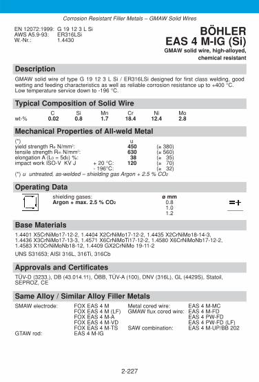
DescriptionGMAW solid wire of type G 19 12 3 L Si / ER316LSi designed for first class welding, good wetting and feeding characteristics as well as reliable corrosion resistance up to +400 °C.Low temperature service down to -196 °C.
Approvals and CertificatesTÜV-D (3233.), DB (43.014.11), ÖBB, TÜV-A (100), DNV (316L), GL (4429S), Statoil,SEPROZ, CE
Base Materials1.4401 X5CrNiMo17-12-2, 1.4404 X2CrNiMo17-12-2, 1.4435 X2CrNiMo18-14-3,1.4436 X3CrNiMo17-13-3, 1.4571 X6CrNiMoTi17-12-2, 1.4580 X6CrNiMoNb17-12-2,1.4583 X10CrNiMoNb18-12, 1.4409 GX2CrNiMo 19-11-2
UNS S31653; AISI 316L, 316Ti, 316Cb
Typical Composition of Solid WireC Si Mn Cr Ni Mo
wt-% 0.02 0.8 1.7 18.4 12.4 2.8
EN 12072:1999: G 19 12 3 L SiAWS A5.9-93: ER316LSiW.-Nr.: 1.4430
BÖHLER EAS 4 M-IG (Si)GMAW solid wire, high-alloyed,
chemical resistant
2-227
Same Alloy / Similar Alloy Filler Metals SMAW electrode: FOX EAS 4 M Metal cored wire: EAS 4 M-MC
FOX EAS 4 M (LF) GMAW flux cored wire: EAS 4 M-FDFOX EAS 4 M-A EAS 4 PW-FDFOX EAS 4 M-VD EAS 4 PW-FD (LF)FOX EAS 4 M-TS SAW combination: EAS 4 M-UP/BB 202
GTAW rod: EAS 4 M-IG
Mechanical Properties of All-weld Metal(*) uyield strength Re N/mm2: 450 (≥ 380)tensile strength Rm N/mm2: 630 (≥ 560)elongation A (L0 = 5d0) %: 38 (≥ 335)impact work ISO-V KV J + 20 °C: 120 (≥ 370)
- 196°C: (≥ 332)(*) u untreated, as-welded – shielding gas Argon + 2.5 % CO2
Operating Datashielding gases: ø mmArgon + max. 2.5 % CO2 0.8
1.01.2
Corrosion Resistant Filler Metals – GMAW Solid Wires

DescriptionGMAW solid wire of type G 19 12 3 Nb Si / ER318Si designed for first class welding, good wetting and feeding characteristics as well as reliable corrosion resistance up to +400 °C.Low temperature service down to -120 °C.
Approvals and CertificatesTÜV-D (3492.), TÜV-A (135), DB (43.014.04), ÖBB, SEPROZ, CE
Base Materials1.4571 X6CrNiMoTi17-12-2, 1.4580 X6CrNiMoNb17-12-2, 1.4401 X5CrNiMo17-12-2,1.4581 GX5CrNiMoNb19-11-2, 1.4437 GX6CrNiMo18-12, 1.4583 X10CrNiMoNb18-12,1.4436 X3CrNiMo17-13-3
AISI 316L, 316Ti, 316Cb
Typical Composition of Solid WireC Si Mn Cr Ni Mo Nb
wt-% 0.035 0.8 1.4 19.0 11.5 2.8 +
EN 12072:1999: G 19 12 3 Nb SiAWS A5.9-93: ER318 (mod.) W.Nr.: 1.4576
BÖHLER SAS 4-IG (Si)GMAW solid wire
high-alloyed, chemical resistant
2-228
Same Alloy Filler Metals SMAW electrode: FOX SAS 4 GTAW rod: SAS 4-IG
FOX SAS 4-A GMAW flux cored wire: SAS 4-FDSAS 4 PW-FD
SAW combination: SAS 4-UP/BB 202
Mechanical Properties of All-weld Metal(*) uyield strength Re N/mm2: 490 (≥ 390)tensile strength Rm N/mm2: 670 (≥ 600)elongation A (L0 = 5d0) %: 33 (≥ 330)impact work ISO-V KV J + 20 °C: 100 (≥ 370)
- 120 °C: (≥ 332)(*) u untreated, as-welded – shielding gas Argon + 2.5 % CO2
Operating Datashielding gases: ø mmArgon + max. 2.5 % CO2 0.8
1.01.2
Corrosion Resistant Filler Metals – GMAW Solid Wires

DescriptionGMAW solid wire for 3-4 % Mo alloyed CrNi-steels like 1.4438 / 317L.The weld metal shows a stable austenitic microstructure with good pitting resistance (PREN > 35)and crevice corrosion resistance as well as excellent CVN toughness behaviour down to -196 °C.BÖHLER ASN 5-IG (Si) has an increased Mo content (4.3 %) to compensate for segregationwhen welding high molybdenum alloyed steels, thus producing equivalent corrosion resistanceto the relevant base metals offering a 3-4 % Mo guarantee. Resistance to intergranular corro-sion up to +400 °C.
Approvals and CertificatesTÜV-D (04139.), DNV (X), GL (4439S), CE
Base Materials1.4436 X3CrNiMo17-13-3, 1.4439 X2CrNiMoN17-13-5, 1.4429 X2CrNiMoN17-13-3,1.4438 X2CrNiMo18-15-4, 1.4583 X10CrNiMoNb18-12
AISI 316Cb, 316 LN, 317LN, 317L, UNS S31726
Typical Composition of Solid WireC Si Mn Cr Ni Mo N PREN FN
wt-% 0.02 0.4 5.5 19.0 17.2 4.3 0.16 37.1 ≤ 0.5
EN 12072:1999: G Z18 16 5 NLAWS A5.9-93: ER317LN (mod.) W.Nr.: 1.4453 (mod.)
BÖHLER ASN 5-IG (Si)GMAW solid wire
high-alloyed, highly corrosion resistant
2-229
Same Alloy/Similar Alloy Filler Metals SMAW electrode: FOX ASN 5 GMAW flux cored wire: E317L-FD*
FOX ASN 5-A E317L PW-FD*GTAW rod: ASN 5-IG SAW combination: ASN 5-UP /BB 203
* for similar alloyed base metals only, not fully austenitic.
Mechanical Properties of All-weld Metal(*) uyield strength Re N/mm2: 430 (≥ 400)tensile strength Rm N/mm2: 650 (≥ 600)elongation A (L0 = 5d0) %: 35 (≥ 330)impact work ISO-V KV J + 20 °C: 110 (≥ 370)
- 196 °C: (≥ 332)(*) u untreated, as-welded – shielding gas Argon + 20 % He + 0.5 % CO2
Operating Datashielding gases: ø mmArgon + 20 - 30 % He + max. 2 % CO2 1.0Argon + 20 % He + 0.5 % CO2 1.2
Corrosion Resistant Filler Metals – GMAW Solid Wires
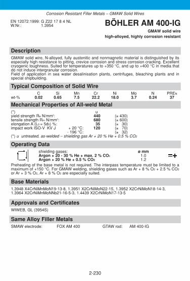
DescriptionGMAW solid wire, N-alloyed, fully austenitic and nonmagnetic material is distinguished by itsespecially high resistance to pitting, crevice corrosion and stress corrosion cracking. Excellentcryogenic toughness. Suited for temperatures up to +350 °C, and up to +400 °C in media thatdo not induce intergranular corrosion. Field of application in sea water desalinisation plants, centrifuges, bleaching plants and inspecial shipbuilding.
Approvals and CertificatesWIWEB, GL (3954S)
Base Materials1.3948 X4CrNiMnMoN19-13-8, 1.3951 X2CrNiMoN22-15, 1.3952 X2CrNiMoN18-14-3,1.3964 X2CrNiMnMoNNb21-16-5-3, 1.4439 X2CrNiMoN17-13-5
Typical Composition of Solid WireC Si Mn Cr Ni Mo N PREN
wt-% 0.02 0.65 7.5 22.2 18.0 3.7 0.24 37
EN 12072:1999: G Z22 17 8 4 NLW.Nr.: 1.3954 BÖHLER AM 400-IG
GMAW solid wire high-alloyed, highly corrosion resistant
2-230
Same Alloy Filler Metals SMAW electrode: FOX AM 400 GTAW rod: AM 400-IG
Mechanical Properties of All-weld Metal(*) uyield strength Re N/mm2: 440 (≥ 430)tensile strength Rm N/mm2: 680 (≥ 600)elongation A (L0 = 5d0) %: 35 (≥ 330)impact work ISO-V KV J + 20 °C: 120 (≥ 370)
- 196 °C: (≥ 332)(*) u untreated, as-welded – shielding gas Ar + 20 % He + 0.5 % CO2
Operating Datashielding gases: ø mmArgon + 20 - 30 % He + max. 2 % CO2 1.0Argon + 20 % He + 0.5 % CO2 1.2
Preheating of the base metal is not required. The interpass temperature must be limited to amaximum of +150 °C. For GMAW welding, shielding gases such as Ar + 8 % O2 + 2.5 % CO2
or Ar + 3 % O2, Ar + 8 % O2 are especially suited.
Corrosion Resistant Filler Metals – GMAW Solid Wires

DescriptionGMAW solid wire for corrosion resistant 4-5 % Mo alloyed CrNi-steels like 1.4539 / 904L. Very high pittingresistant equivalent (PREN ≥ 45) – pitting potential (%Cr + 3.3 x %Mo + 30 x %N). Due to the high Mo con-tent (6.2 %) in comparison to W.-No. 1.4539 respectively UNS N08904, the high segregation rate of high Mo-alloyed CrNi-weld metal can be compensated. The fully austenitic weld metal possess a marked resistancetowards pitting and crevice corrosion in chloride containing media. Highly resistant against sulphur-, phos-phorus-, acetic- and formic acid, as well as sea- and brackish water. Caused from the low C-content of theweld metal, the risk of intergranular corrosion can be avoided. The high Ni-content in comparison to standardCrNi-weld metals leads to high resistance against stress corrosion cracking. Special applicable in sulphur- and phosphorus production, pulp and paper industry, flue gas desulphurisationplants, further on for fertilizer production, petrochemical industry, fatty-, acetic- and formic acid production, seawater sludge fittings and pickling plants which are proceeded with sea or brackish water.The GMAW wire exhibits good feeding, welding and wetting characteristics.
Approvals and CertificatesTÜV-D (4897.), TÜV-A (476), Statoil, SEPROZ, CE
Base Materialssame-alloyed CrNi-steels with high Mo-content1.4539 X1NiCrMoCu25-20-5, 1.4439 X2CrNiMoN17-13-5, 1.4537 X1CrNiMoCuN25-25-5UNS N08904, S31726
Typical Composition of Solid WireC Si Mn Cr Ni Mo Cu N PREN
wt-% ≤0.02 0.7 4.7 20.0 25.4 6.2 1.5 0.12 ≥ 45.0
EN 12072:1999: G Z20 25 5 Cu NLAWS A5.9-93: ER385 (mod.)W.Nr.: 1.4519 (mod.)
BÖHLER CN 20/25 M-IG (Si)
GMAW solid wire high-alloyed, highly corrosion resistant
2-231
Same Alloy Filler Metals SMAW electrode: FOX CN 20/25 M GTAW rod: CN 20/25 M-IG
FOX CN 20/25 M-A
Mechanical Properties of All-weld Metal(*) uyield strength Re N/mm2: 410 (≥ 350)tensile strength Rm N/mm2: 650 (≥ 600)elongation A (L0 = 5d0) %: 39 (≥ 330)impact work ISO-V KV J + 20 °C: 100 (≥ 370)
- 196 °C: (≥ 332)(*) u untreated, as-welded – shielding gas Ar + 20 % He + 0.5 % CO2
Operating Datashielding gases: ø mmArgon + 20 - 30 % He + max. 2 % CO2 0.8Argon + 20 % He + 0.5 % CO2 1.0
1.2Preheating and post weld heat treatment is not required by the deposit. Interpass temperature should not exceed +150 °C.
Corrosion Resistant Filler Metals – GMAW Solid Wires

DescriptionGMAW solid wire particularly suitable for welding of ferritic-austenitic duplex steels. By virtue ofspecific alloy composition which includes an extremely low oxygen content the deposit has, inaddition to high tensile strength and toughness, also excellent resistance to stress corrosioncracking and pitting (PREN >35). In order to ensure good deposit properties, care must be takento achieve controlled dilution and thorough back purging. Ferrite content 30 – 60 FN (WRC).Suited for temperatures down to -40 °C and up to +250 °C. The wire exhibits good feeding,welding and wetting characteristics of the wire. The preferred gas for MIG welding is Argon+ 20 % Helium + 2 % CO2.
Approvals and CertificatesTÜV-D (4483.), TÜV-A (424), DB (43.014.26), DNV (X), GL (4462S), Statoil, SEPROZ, CE
Base Materialssame-alloyed duplex steels, as well as similar-alloyed, ferritic-austenitic steels with highertensile strength
1.4462 X2CrNiMoN22-5-3, 1.4362 X2CrNiN23-4,1.4462 X2CrNiMoN22-5-3 together with 1.4583 X10CrNiMoNb18-12,1.4462 X2CrNiMoN22-5-3 together with P235GH / P265GH, S255N, P295GH, S355N, 16Mo3
UNS S31803, S32205
Typical Composition of Solid WireC Si Mn Cr Ni Mo N PREN
wt-% ≤0.015 0.4 1.7 22.5 8.8 3.2 0.15 ≥ 35
EN 12072:1999: G 22 9 3 NLAWS A5.9-93: ER2209W.Nr.: 1.4462 (mod.)
BÖHLER CN 22/9 N-IGGMAW solid wire
high-alloyed, highly corrosion resistant
2-232
Same Alloy Filler Metals SMAW electrode: FOX CN 22/9 N-B GMAW flux cored wire: CN 22/9 N-FD
FOX CN 22/9 N CN 22/9 PW-FDGTAW rod: CN 22/9 N-IG SAW combination: CN 22/9 N-UP/BB 202
Mechanical Properties of All-weld Metal(*) uyield strength Re N/mm2: 660 (≥ 600)tensile strength Rm N/mm2: 830 (≥ 720)elongation A (L0 = 5d0) %: 28 (≥ 325)impact work ISO-V KV J + 20 °C: 85 (≥ 370)
- 40 °C: (≥ 332)(*) u untreated, as-welded – shielding gas Ar + 20 % He + 2 % CO2
Operating Datashielding gases: ø mmArgon + 20 - 30 % He + max. 2 % CO2 1.0Argon + 20 - 30 % He + max. 1 % O2 1.2
Preheating and post weld heat treatment is not required be the weld deposit.Interpass temperature should not exceed +150 °C.
Corrosion Resistant Filler Metals – GMAW Solid Wires

2-233
DescriptionGMAW solid wire highly suitable for welding ferritic-austenitic superduplex steels. By virtue ofspecific alloy composition the deposit has, in addition to high tensile strength and toughness,also excellent resistance to stress corrosion cracking and pitting corrosion. The operating tem-perature is -50 °C up to +250 °C. Well suited for the conditions in the offshore field.For applications requiring low Hydrogen, we offer the product BÖHLER CN 25/9 CuT-IG-LHwith Hydrogen Content guaranteed less than 3 ppm.
Approvals and Certificates–
Same Alloy Filler MetalsStick electrode: FOX CN 25/9 CuTGTAW rod: CN 25/9 CuT-IG
Base Materials25 % Cr-Superduplex steels e.g.1.4501 X2CrNiMoCuWN 25-7-4UNS S 32750, S 32760 ZERON 100, SAF 25/07, FALC 100
Operating Datashielding gas: ø mmArgon + 20-30 % He + 0.5-2 % CO2 1.0Argon + 20-30 % He + max. 1 % O2 1.2
Mechanical Properties of All-weld Metal(*) uyield strength Re N/mm2: ≥ 650tensile strength Rm N/mm2: ≥ 750elongation A (L0=5d0) %: ≥ 25impact work ISO-V Av J +20 °C: ≥ 80
-50 °C: 50
(*) untreated, as welded – shielding gas Argon + He + 0,5 % CO2
Typical Composition of Solid WireC Si Mn Cr Ni Mo N Cu W PREN
wt-% 0.02 0.3 0.7 25.2 9.2 3.6 0.22 0.6 0.62 ≥ 40
EN 12072:1999: G 25 9 4 NLAWS A5.9-93: ER2553 (mod.) BÖHLER
CN 25/9 CuT-IGGMAW solid wire
high alloyed, highly corrosion resistant
Corrosion Resistant Filler Metals – GMAW Solid Wires

DescriptionMetal cored wire for the fabrication and repair welding of hydro turbine components made of softmartensitic 13 % Cr 4 % Ni alloyed steels and cast steels.BÖHLER CN 13/4-MC offers favourable spray arc or pulsarc characteristics, minimum spatterformation, flat and smooth bead profiles, excellent wetting behaviour and safe penetration. It is easy to operate in all welding positions.Additionally, precise alloy adjustment ensure very good impact test results of the heat treatedweld metal. The hydrogen content is extra low (maximum 4 ml/100 g acc. AWS conditions).Significant gains in productivity can be realized by higher deposition rates and reduced postweld grinding when compared to GMAW using solid wires.
Approvals and CertificatesSEPROZ
Base Materials1.4317 GX4CrNi13-4, 1.4313 X3CrNiMo13-4, 1.4351 X3CrNiMo 13-4, ACI Grade CA 6 NM,1.4414 GX4CrNiMo13-4
Typical Composition of All-weld MetalC Si Mn Cr Ni Mo
wt-% ≤ 0.025 0.7 0.9 12.0 4.6 0.6
ENISO 17633-A:2006: T 13 4 MM 2ENISO 17633-B:2006: TS 410NiMo-MG1 (mod.)AWS A5.9-93: EC410NiMo (mod.)
BÖHLER CN 13/4-MCMetal cored wire,
high alloyed, stainless
2-234
Same Alloy Filler Metals SMAW electrode: FOX CN 13/4 GMAW solid wire: CN 13/4-IG
FOX CN 13/4 SUPRA Metal cored wire: CN 13/4-MC (F)GTAW rod: CN 13/4-IG SAW combination: CN 13/4-UP/BB 203
Mechanical Properties of All-weld Metal(*) u ayield strength Re N/mm2: 800 (≥ 750) 760 (≥ 680)tensile strength Rm N/mm2: 990 (≥ 950) 900 (≥ 800)elongation A (L0 = 5d0) %: 12 (≥ 310) 16 (≥ 315)impact work ISO-V KV J +20 °C: 40 (≥ 330) 65 (≥ 350)
-20 °C: 60 (≥ 347)(*) u untreated, as-welded – shielding gas Ar + 2.5 % CO2
a annealed, 580 °C/8 h/furnace down to 300 °C/Air – shielding gas Ar + 2,5 % CO2
Operating DataShielding gas: ø mm amps A voltage VArgon + 2.5 % CO2 1.2 130 - 370 16 - 38
1.6 250 - 550 22 - 40Welding with conventional or pulsed power sources (preferably slightly trailing torch position, angel appr. 80 °). Recommended stick out 18 - 20 mm and length of arc 3 - 5 mm.Recommended preheating and interpass temperatures in case of heavy wall thicknesses are 100 - 160 °C. Maximum heat input 15 kJ/cm. Tempering at 580 - 620 °C.
Corrosion Resistant Filler Metals – Metal cored Wires

2-235
DescriptionMetal cored wire for welding of hydro turbine components made of soft martensitic13 % Cr 4 % Ni alloyed cast steels.BÖHLER CN 13/4-MC (F) offers favourable spray arc or pulsarc characteristics, minimumspatter formation, flat and smooth bead profiles, excellent wetting behaviour and safe penetra-tion. It is easy to operate in all welding positions.The hydrogen content is low (maximum 5 ml/100 g acc. to AWS A 4.3-93).Significant gains in productivity can be realized by higher deposition rates and reduced postweld grinding when compared to GMAW using solid wires.
Approvals and Certificates–
Base Materials1.4317 GX4CrNi13-4, 1.4313 X3CrNiMo13-4, 1.4351 X3CrNiMo 13-4, ACI Grade CA6NM, 1.4414 GX4CrNiMo13-4
Typical Composition of All-weld MetalC Si Mn Cr Ni Mo
wt-% ≤ 0.03 0.7 0.9 12.2 4.6 0.6
ENISO 17633-A:2006: T 13 4 MM 2ENISO 17633-B:2006: TS 410NiMo-MG1 (mod.)AWS A5.9-93: EC410NiMo (mod.)
BÖHLER CN 13/4-MC (F)
Metal cored wire,high alloyed, stainless
Same Alloy Filler Metals SMAW electrode: FOX CN 13/4 GMAW solid wire: CN 13/4-IG
FOX CN 13/4 SUPRA Metal cored wire: CN 13/4-MCGTAW rod: CN 13/4-IG SAW combination: CN 13/4-UP/BB 203
Mechanical Properties of All-weld Metal(*) ayield strength Re N/mm2: 700 (≥ 680)tensile strength Rm N/mm2: 880 (≥ 800)elongation A (L0 = 5d0) %: 16 (≥ 315)Impact strength ISO-V KV J +20 °C: 55
-20 °C: 45
(*) a annealed/tempered, 580 °C/8 h/furnace to 300 °C/air – shielding gas Argon + 2,5 % CO2
Operating DataShielding gas: ø mm amps A voltage VArgon + 2.5 % CO2 1.2 130 - 370 16 - 38
1.6 250 - 550 22 - 40Welding with conventional or pulsed power sources (preferably slightly trailing torch position, angel appr. 80 °). Recommended stick out 18-20 mm and length of arc 3-5 mm. Recommended preheating and interpass temperatures in case of heavy wall thicknesses are 100-160 °C. Maximum heat input 15 kJ/cm. Tempering at 580-620 °C. Positional weldability of metal cored wires is similar to solid wires.
Corrosion Resistant Filler Metals – Metal cored Wires

2-236
DescriptionBöhler EAS 2-MC is an austenitic CrNi-metal cored wire for GMAW applicable for same orsimilar alloyed, stabilized or non stabilized, corrosion resistant CrNi-steels. Suitable for servicetemperatures from -196 °C to +350 °C. This product achieves high productivity and is easy tooperate. It provides excellent welding characteristics, smooth almost spatter free weld finish.The wider arc, in comparison to solid wire, will reduce the risk of lack of fusion and is lesssensitive against misalignment of edges and different gap widths.
Approvals and CertificatesTÜV-D (09987.00), CE
Base Materials1.4306 X2CrNi19-11, AISI 304 L, 1.4301 X5CrNi18-10, AISI 304,1.4308 GX6CrNi18-9,1.4311 X2CrNiN18-10, ASTM A320 Gr. B8C or D, AISI 304 LN,1.4312 GX10CrNi18-8, ASTM A157 Gr. C9, AISI 302, 1.4541 X6CrNiTi18-10, AISI 321,1.4546 X5CrNiNb18-10, AISI 321, 1.4550 X6CrNiNb18-10, AISI 347, 1.4552 GX5CrNiNb18-9
Typical Composition of All-weld MetalC Si Mn Cr Ni
wt-% ≤ 0.03 0.6 1.4 19.8 10.5
ENISO 17633-A:2006: T 19 9 L MM 1ENISO 17633-B:2006: TS308L-MG1AWS A5.9-93: EC308L
BÖHLER EAS 2-MCMetal cored wire, high-alloyed,
chemical resistant
Same Alloy / Similar Alloy Filler Metals SMAW electrode: FOX EAS 2 GTAW-rod: EAS 2-IG
FOX EAS 2-A GMAW solid wire: EAS 2-IG (Si)FOX EAS 2-VD GMAW flux cored wire: EAS 2 PW-FD
EAS 2 PW-FD (LF)EAS 2-FD
SAW combination: EAS 2-UP/BB 202
Mechanical Properties of All-weld Metal(*) uyield strength Re N/mm2: 380 (≥ 350)tensile strength Rm N/mm2: 540 (≥ 520)elongation A (L0 = 5d0) %: 37 (≥ 335)impact work ISO-V KV J + 20 °C: 105 (≥ 347)
- 196 °C: 50 (≥ 332)
(*) u untreated, as-welded – shielding gas Ar + 2.5 % CO2
Operating DataShielding gas: ø mm amps A voltage VArgon + 2.5 % CO2 1.2 60 - 280 13 - 30
1.6 100 - 370 13 - 32Welding with conventional or pulsed power sources (preferably slightly leading torch position, angel appr. 80 °). Recommended stick out 15-20 mm and length of arc 3-5 mm.Positional weldability of metal cored wires is similar to solid wires (puls arc welding is recommended).
Corrosion Resistant Filler Metals – Metal cored Wires

2-237
DescriptionBöhler EAS 4 M-MC is an austenitic CrNiMo-metal cored wire for GMAW applicable for same orsimilar alloyed, stabilized or non stabilized, corrosion resistant CrNiMo-steels. Suitable forservice temperatures from -196 °C to +400 °C. This product achieves high productivity and iseasy to operate. It provides excellent welding characteristics, smooth almost spatter free weldfinish. The wider arc, in comparison to solid wire, will reduce the risk of lack of fusion and is lesssensitive against misalignment of edges and different gap widths.
Approvals and CertificatesTÜV-D (09988.00), CE
Base Materials1.4401 X5CrNiMo17-12-2, 1.4404 X2CrNiMo17-12-2, 1.4435 X2CrNiMo18-14-3,1.4436 X3CrNiMo17-13-3, 1.4571 X6CrNiMoTi17-12-2, 1.4580 X6CrNiMoNb17-12-2,1.4583 X10CrNiMoNb18-12, 1.4409 GX2CrNiMo 19-11-2UNS S31653, AISI 316L, 316Ti, 316Cb
Typical Composition of All-weld MetalC Si Mn Cr Ni Mo
wt-% ≤ 0.03 0.6 1.4 18.8 12.2 2.7
ENISO 17633-A:2006: T 19 12 3 L MM 1ENISO 17633-B:2006: TS316L-MG1AWS A5.9-93: EC316L
BÖHLER EAS 4 M-MC
Metal cored wirehigh-alloyed, chemical resistant
Same Alloy / Similar Alloy Filler Metals SMAW electrode: FOX EAS 4 M GTAW rod: EAS 4 M-IG
FOX EAS 4 M (LF) GMAW flux cored wire: EAS 4 M-FDFOX EAS 4 M-A EAS 4 PW-FDFOX EAS 4 M-VD EAS 4 PW-FD (LF)FOX EAS 4 M-TS SAW combination: EAS 4 M-UP/BB 202
Mechanical Properties of All-weld Metal(*) uyield strength Re N/mm2: 410 (≥ 350)tensile strength Rm N/mm2: 560 (≥ 520)elongation A (L0 = 5d0) %: 34 (≥ 330)impact work ISO-V KV J +20 °C: 80 (≥ 347)
-196 °C: (≥ 332)
(*) u untreated, as-welded – shielding gas Ar + 2.5 % CO2
Operating DataShielding gas: ø mm amps A voltage VArgon + 2.5 % CO2 1.2 60 - 280 13 - 30
1.6 100 - 370 13 - 32Welding with conventional or pulsed power sources (preferably slightly leading torch position, angel appr. 80 °). Recommended stick out 15-20 mm and length of arc 3-5 mm.Positional weldability of metal cored wires is similar to solid wires (puls arc welding is recommended).
Corrosion Resistant Filler Metals – Metal cored Wires

DescriptionRutile strip alloyed flux cored welding wire of type T 19 9 L R / E308LT0 for GMAW of stainless steelslike 1.4306 / 304L. This product achieves high productivity and is easy to operate providing excellentoperating characteristics, self releasing slag, almost no spatter formation and temper discoloration,smooth weld finish and safe penetration. Increased travel speeds as well as little demand for cleaningand pickling provide considerable savings in time and money. Suitable for service temperatures from -196 °C to +350 °C. BÖHLER EAS 2-FD ø 0.9 mm is well suitable for welding of sheet metal from 1.5mm and ø 1.2 mm can be used for wall thicknesses from 3 mm upwards. Wire ø 0.9 mm is designedfor positional welding, wire ø 1.2 mm and 1.6 mm are recommended mainly for downhand andhorizontal welding positions as well as in position PC/2G and slightly vertical down.
Approvals and CertificatesTÜV-D (5348.), DB (43.014.14), ÖBB, TÜV-A (514), CWB (E308LT0-1(4)), GL (4550 (C1, M21)), SEPROZ, CE
Base Materials1.4306 X2CrNi19-11, 1.4301 X5CrNi18-10, 1.4311 X2CrNiN18-10, 1.4312 GX10CrNi18-8,1.4541 X6CrNiTi18-10, 1.4546 X5CrNiNb18-10, 1.4550 X6CrNiNb18-10AISI 304, 304L, 304LN, 302, 321, 347; ASTM A157 Gr. C9; A320 Gr. B8C or D
Typical Composition of All-weld MetalC Si Mn Cr Ni
wt-% 0.03 0.7 1.5 19.8 10.5
ENISO 17633-A:2006: T 19 9 L R M (C) 3ENISO 17633-B:2006: TS308L-FB0AWS A5.22-95: E308LT0-4
E308LT0-1ENISO 17633-A:2006: T 19 9 L P M (C) 1 (for ø 0.9 mm)ENISO 17633-B:2006: TS308L-FB1AWS A5.22-95: E308LT1-4/-1 (for ø 0.9 mm)
BÖHLER EAS 2-FDGMAW flux cored wire, high-alloyed,
chemical resistant
2-238
Same Alloy / Similar Alloy Filler Metals SMAW electrode: FOX EAS 2 GMAW solid wire: EAS 2-IG (Si)
FOX EAS 2-A Metal cored wire: EAS 2-MCFOX EAS 2-VD GMAW flux cored wire: EAS 2 PW-FD
GTAW rod: EAS 2-IG EAS 2 PW-FD (LF)SAW combination: EAS 2-UP/BB 202
Mechanical Properties of All-weld Metal(*) uyield strength Re N/mm2: 380 (≥ 350)tensile strength Rm N/mm2: 560 (≥ 520)elongation A (L0 = 5d0) %: 40 (≥ 335)impact work ISO-V KV J +20 °C: 60 (≥ 347)
-196 °C: 35 (≥ 332)(*) u untreated, as-welded – shielding gas Ar + 18 % CO2
Operating Datare-drying: possible, 150 °C/24 h ø mm amps A voltage Vshielding gases: 0.9 100 - 160 21 - 30Argon + 15 - 25 % CO2 1.2 125 - 280 20 - 34100 % CO2 1.6 200 - 350 25 - 35
welding with standard GMAW-facilities possible, slightly trailing torch position (angel appr. 80 °), when using 100 % CO2 as shielding gas it is necessary to increase the voltage by 2 V; the gas flow should be 15 - 18 l/min
Corrosion Resistant Filler Metals – GMAW Flux-cored WiresØ
0.9
Ø 1
.2Ø
1.6

DescriptionRutile strip alloyed flux cored welding wire with fast freezing slag providing excellent positional opera-ting characteristics and fast travel speeds. It is easy to use and operates with a powerful penetratingspray arc transfer, minimum spatter formation and self releasing slag. This flux cored welding wire offersmany economical and quality advantages over solid wire pulse arc welding. High deposition rates andproductivity gains are easily achievable. Additional cost effective benefits are offered through use of lessexpensive shielding gases (Argon +15 - 25 % CO2 or 100 % CO2), good wetting characteristics (lessgrinding), little temper discoloration & bead oxidation (less pickling expenses), easy operation and safepenetration (reduces the risk of weld defects and associated repair work costs), and smooth and cleanweld finish (less post weld work). Due to its characteristics mainly for positional welding and service tem-peratures between -196 °C to - +350 °C. For downhand & horizontal welding positions (1G, 1F, 2F) ourflux cored wire BÖHLER EAS 2-FD should be preferred.
Approvals and CertificatesTÜV-D (09117.), DB (43.014.23), ÖBB, CWB (E308LT1-1(4)), SEPROZ, CE
Same Alloy / Similar Alloy Filler Metals SMAW electrode: FOX EAS 2 GMAW solid wire: EAS 2-IG (Si)
FOX EAS 2-A Metal cored wire: EAS 2-MCFOX EAS 2-VD GMAW flux cored wire: EAS 2-FD
GTAW rod: EAS 2-IG EAS 2 PW-FD (LF)SAW combination: EAS 2-UP/BB202
Base Materials1.4306 X2CrNi19-11, 1.4301 X5CrNi18-10, 1.4311 X2CrNiN18-10, 1.4312 GX10CrNi18-8,1.4541 X6CrNiTi18-10, 1.4546 X5CrNiNb18-10, 1.4550 X6CrNiNb18-10AISI 304, 304L, 304LN, 302, 321, 347; ASTM A157 Gr. C9; A320 Gr. B8C or D
Operating Datare-drying: ø mm amps A voltage Vpossible, 150 °C / 24 h 1.2 100 - 220 20 - 31shielding gases: 1.6 175 - 260 21 -29Argon + 15 - 25 % CO2
100 % CO2
Welding with standard GMAW-facilities possible, slightly trailing torch position (angel appr. 80 °), slightweaving is recommended for positional welding; when using 100 % CO2 as shielding gas it is neces-sary to increase the voltage by 2 V; the gas flow should be 15 - 18 l/min
Mechanical Properties of All-weld Metal(*) uyield strength Re N/mm2: 380 (≥ 350)tensile strength Rm N/mm2: 560 (≥ 520)elongation A (L0 = 5d0) %: 40 (≥ 335)impact work ISO-V KV J +20 °C: 70 (≥ 347)
-196 °C: 40 (≥ 332)(*) u untreated, as-welded – shielding gas Ar + 18 % CO2
Typical Composition of All-weld MetalC Si Mn Cr Ni
wt-% 0.03 0.7 1.5 19.8 10.5
ENISO 17633-A:2006: T 19 9 L P M 1T 19 9 L P C 1
ENISO 17633-B:2006: TS308L-FB1AWS A5.22-95: E308LT1-4
E308LT1-1
BÖHLER EAS 2 PW-FDGMAW flux cored wire, high-alloyed,
chemical resistant
2-239
Corrosion Resistant Filler Metals – GMAW Flux-cored Wires

DescriptionRutile flux cored welding wire, with controlled weld metal ferrite content (FN 3-6), particularly forgood cryogenic toughness and lateral expansion down to -196 °C like specified for LNG appli-cations. The slag system of the wire provides excellent positional welding characteristics andfast travel speeds.
Approvals and CertificatesTÜV-D (09117.), CE
Same Alloy Filler Metals SMAW electrode: FOX EAS 2 GMAW solid wire: EAS 2-IG (Si)
FOX EAS 2-A Metal cored wire: EAS 2-MCFOX EAS 2-VD GMAW flux cored wire: EAS 2-FD
GTAW rod: EAS 2-IG EAS 2 PW-FDSAW combination: EAS 2-UP/BB202
Base Materials1.4306 X2CrNi19-11, 1.4301 X5CrNi18-10, 1.4311 X2CrNiN18-10, 1.4312 GX10CrNi18-8,1.4541 X6CrNiTi18-10, 1.4546 X5CrNiNb18-10, 1.4550 X6CrNiNb18-10AISI 304, 304L, 304LN, 302, 321, 347; ASTM A157 Gr. C9; A320 Gr. B8C or D
Operating Datare-drying: ø mm amps A voltage Vpossible, 150 °C / 24 h 1.2 100 - 220 20 - 31shielding gases: 1.6 175 - 260 21 -29Argon + 15 - 25 % CO2
100 % CO2
Welding with standard GMAW-facilities possible, slightly trailing torch position (angel appr. 80 °), slightweaving is recommended for positional welding; when using 100 % CO2 as shielding gas it is necessaryto increase the voltage by 2 V; the gas flow should be 15 - 18 l/min
Mechanical Properties of All-weld Metal(*) uyield strength Re N/mm2: 390 (≥ 350)tensile strength Rm N/mm2: 550 (≥ 520)elongation A (L0 = 5d0) %: 40 (≥ 335)impact work ISO-V KV J +20 °C: 78 (≥ 347)
-196 °C: 45 (≥ 332)lateral expansion (mm) -196 °C: (≥0.38)(*) u untreated, as-welded – shielding gas Ar + 18 % CO2
Typical Composition of All-weld MetalC Si Mn Cr Ni FN
wt-% 0.03 0.6 1.4 19.3 10.9 3 - 6
ENISO 17633-A:2006: T 19 9 L P M 1T 19 9 L P C 1
ENISO 17633-B:2006: TS308L-FB1AWS A5.22-95: E308LT1-4
E308LT1-1
BÖHLER EAS 2 PW-FD (LF)GMAW flux cored wire, high-alloyed,
chemical resistant
2-240
Corrosion Resistant Filler Metals – GMAW Flux-cored Wires

DescriptionRutile strip alloyed flux cored welding wire of type T 19 9 Nb R / E347LT0 for GMAW of stainless steelslike 1.4546 / 347.BÖHLER SAS 2-FD is designed for single and multi-pass welding mainly in the flat and horizontal position, horizontal/vertical position as well as the slightly vertical-down position (1 o'clock).This product achieves high productivity and is easy to operate providing excellent operating characteri-stics, self releasing slag, almost no spatter formation and temper discoloration, smooth weld finish andsafe penetration.Increased travel speeds as well as little demand for cleaning and pickling provide considerable savingsin time and money. Suitable for service temperatures from -196 °C to +400 °C.
Approvals and CertificatesTÜV-D (09740.), SEPROZ, CE
Same Alloy Filler Metals SMAW electrode: FOX SAS 2 GMAW solid wire: SAS 2-IG (Si)
FOX SAS 2-A GMAW flux cored wire: SAS 2 PW-FDGTAW rod: SAS 2-IG SAW combination: SAS 2-UP/BB 202
Base Materials1.4550 X6CrNiNb18-10, 1.4541 X6CrNiTi18-10, 1.4552 GX5CrNiNb19-11, 1.4301 X5CrNi18-10,1.4312 GX10CrNi18-8, 1.4546 X5CrNiNb18-10, 1.4311 X2CrNiN18-10, 1.4306 X2CrNi19-11
AISI 347, 321, 302, 304, 304L, 304LN; ASTM A296 Gr. CF 8 C; A157 Gr. C9; A320 Gr. B8C or D
Operating Datare-drying: ø mm amps A voltage Vpossible, 150 °C / 24 h 1.2 125 - 280 20 - 34shielding gases: 1.6 200 - 350 25 - 35Argon + 15 - 25 % CO2
100 % CO2
Welding with standard GMAW-facilities possible slightly trailing torch position (angel appr. 80 °), when using 100 % CO2 as shielding gas it is necessary to increase the voltage by 2 V; the gas flow should be 15 - 18 l/min
Mechanical Properties of All-weld Metal(*) uyield strength Re N/mm2: 420 (≥ 380)tensile strength Rm N/mm2: 600 (≥ 560)elongation A (L0 = 5d0) %: 35 (≥ 330)impact work ISO-V KV J +20 °C: 75 (≥ 347)
-120 °C: 45 (≥ 332)-196 °C: (≥ 332)
(*) u untreated, as-welded – shielding gas Ar + 18 % CO2
Typical Composition of All-weld MetalC Si Mn Cr Ni Nb
wt-% 0.03 0.6 1.4 19.0 10.4 +
ENISO 17633-A:2006: T 19 9 Nb R M 3T 19 9 Nb R C 3
ENISO 17633-B:2006: TS347-FB0AWS A5.22-95: E347T0-4
E347T0-1
BÖHLER SAS 2-FDGMAW flux cored wire, high-alloyed,
chemical resistant
2-241
Corrosion Resistant Filler Metals – GMAW Flux-cored WiresØ
1.2
Ø 1
.6

DescriptionRutile strip alloyed flux cored welding wire with fast freezing slag providing excellent positional opera-ting characteristics and fast travel speeds. It is easy to use and operates with a powerful penetratingspray arc transfer, minimum spatter formation and self releasing slag.This flux cored welding wire offers many economical and quality advantages over solid wire pulse arcwelding. High deposition rates and productivity gains are easily achievable. Additional cost effectivebenefits are offered through use of less expensive shielding gases, good wetting characteristics (lessgrinding), little temper discoloration & bead oxidation (less pickling expenses), easy operation and safepenetration (reduces the risk of weld defects and associated repair work costs), and smooth and cleanweld finish (less post weld work).Due to its characteristics mainly for positional welding and service temperatures between -120 °C to+400 °C. For downhand and horizontal welding positions (1G, 1F, 2F) our flux cored wire BÖHLERSAS 2FD should be preferred.
Approvals and CertificatesTÜV-D (10059.), SEPROZ, CE
Same Alloy Filler Metals SMAW electrode: FOX SAS 2 GMAW solid wire: SAS 2-IG (Si)
FOX SAS 2-A GMAW flux cored wire: SAS 2-FDGTAW rod: SAS 2-IG SAW combination: SAS 2-UP/BB 202
Base Materials1.4550 X6CrNiNb18-10, 1.4541 X6CrNiTi18-10, 1.4552 GX5CrNiNb19-11, 1.4301 X5CrNi18-10,1.4312 GX10CrNi18-8, 1.4546 X5CrNiNb18-10, 1.4311 X2CrNiN18-10, 1.4306 X2CrNi19-11
AISI 347, 321, 302, 304, 304L, 304LN; ASTM A296 Gr. CF 8 C; A157 Gr. C9; A320 Gr. B8C or D
Operating Datare-drying: ø mm amps A voltage Vpossible, 150 °C / 24 h 1.2 100 - 220 20 - 31shielding gases:Argon + 15 - 25 % CO2
100 % CO2
Welding with standard GMAW-facilities possible, slightly trailing torch position (angel appr. 80 °), slightweaving is recommended for positional welding; when using 100 % CO2 as shielding gas it is necessaryto increase the voltage by 2 V; the gas flow should be 15 - 18 l/min.
Mechanical Properties of All-weld Metal(*) uyield strength Re N/mm2: 420 (≥ 380)tensile strength Rm N/mm2: 600 (≥ 560)elongation A (L0 = 5d0) %: 35 (≥ 330)impact work ISO-V KV J + 20 °C: 75 (≥ 347)
- 120 °C: 38 (≥ 332)(*) u untreated, as-welded – shielding gas Ar + 18 % CO2
Typical Composition of All-weld MetalC Si Mn Cr Ni Nb
wt-% 0.03 0.7 1.4 19.0 10.4 +
ENISO 17633-A:2006: T 19 9 Nb P M 1T 19 9 Nb P C 1
ENISO 17633-B:2006: TS347-FB1AWS A5.22-95: E347T1-4
E347T1-1
BÖHLER SAS 2 PW-FDGMAW flux cored wire, high-alloyed,
chemical resistant
2-242
Corrosion Resistant Filler Metals – GMAW Flux-cored Wires

Operating Datare-drying: possible, 150 °C/24 h ø mm amps A voltage Vshielding gases: 0.9 100 - 160 21 - 30Argon + 15 - 25 % CO2 1.2 125 - 280 20 - 34100 % CO2 1.6 200 - 350 25 - 35
Welding with standard GMAW-facilities possible, slightly trailing torch position (angel appr. 80 °), when using 100 % CO2 as shielding gas it is necessary to increase the voltage by 2 V; the gas flow should be 15 - 18 l/min
Ø 0
.9Ø
1.2
Ø 1
.6
DescriptionRutile flux cored welding wire of type T 19 12 3 L R / E316LT0 for GMAW of stainless steels like 1.4435 / 316L. This product achieves high productivity and is easy to operate providing excellent operating characteristics, selfreleasing slag, almost no spatter formation and temper discoloration, smooth weld finish and safe penetration.Increased travel speeds as well as little demand for cleaning and pickling provide considerable savings in time andmoney. Suitable for service temperatures of -120 °C to +400 °C. Resists intergranular corrosion up to +400 °C.BÖHLER EAS 4 M-FD ø 0.9 mm is well suitable for welding of sheet metal from 1.5 to 3 mm (out of position > 5 mm) and ø 1.2 mm can be used for wall thicknesses from 3 mm and up. Wire ø 0.9 mm is designed for positional welding, wire ø 1.2 mm and 1.6 mm are recommended mainly for downhand and horizontal welding positions, horizontal/vertical position as well as the slightly vertical-down position (1 o'clock).
Approvals and CertificatesTÜV-D (5349.), DB (43.014.15), ÖBB, TÜV-A (515), CWB (E316LT0-1(4)), LR (DX, BF, 316LS), GL (4571 (C1, M21)), SEPROZ, CE
Base Materials1.4401 X5CrNiMo17-12-2, 1.4404 X2CrNiMo17-12-2, 1.4435 X2CrNiMo18-14-3,1.4436 X3CrNiMo17-13-3, 1.4571 X6CrNiMoTi17-12-2, 1.4580 X6CrNiMoNb17-12-2,1.4583 X10CrNiMoNb18-12, 1.4409 GX2CrNiMo 19-11-2UNS S31653; AISI 316L, 316Ti, 316Cb
Typical Composition of All-weld MetalC Si Mn Cr Ni Mo
wt-% 0.03 0.7 1.5 19.0 12.0 2.7
ENISO 17633-A:2006: T 19 12 3 L R M (C) 3ENISO 17633-B:2006: TS316L-FB0AWS A5.22-95: E316LT0-4
E316LT0-1ENISO 17633-A:2006: T 19 12 3 L P M (C) 1 (for ø 0.9 mm)ENISO 17633-B:2006: TS316L-FB1AWS A5.22-95: E316LT1-4/-1 (for ø 0.9 mm)
BÖHLER EAS 4 M-FDGMAW flux cored wire, high-alloyed,
chemical resistant
2-243
Mechanical Properties of All-weld Metal(*) uyield strength Re N/mm2: 400 (≥ 350)tensile strength Rm N/mm2: 560 (≥ 520)elongation A (L0 = 5d0) %: 38 (≥ 330)impact work ISO-V KV J + 20 °C: 55 (≥ 347)
- 120 °C: 35 (≥ 332)(*) u untreated, as-welded – shielding gas Ar + 18 % CO2
Same Alloy / Similar Alloy Filler Metals SMAW electrode: FOX EAS 4 M GMAW solid wire: EAS 4 M-IG (Si)
FOX EAS 4 M (LF) Metal cored wire: EAS 4 M-MCFOX EAS 4 M-A GMAW flux cored wire: EAS 4 PW-FDFOX EAS 4 M-VD EAS 4 PW-FD (LF)FOX EAS 4 M-TS SAW combination: EAS 4 M-UP/BB 202
GTAW rod: EAS 4 M-IG
Corrosion Resistant Filler Metals – GMAW Flux-cored Wires

DescriptionBÖHLER EAS 4 PW-FD is a rutile flux cored welding wire with fast freezing slag providing excellent positionaloperating characteristics and fast travel speeds. It is easy to use and operates with a powerful penetratingspray arc transfer, minimum spatter formation and self releasing slag.This flux cored welding wire offers many economical and quality advantages over solid wire pulse arc welding.High deposition rates and productivity gains are easily achievable. Additional cost effective benefits are offeredthrough use of less expensive shielding gases (Argon +15-25 % CO2 or 100 % CO2), good wetting characteri-stics (less grinding), little temper discoloration & bead oxidation (less pickling expenses), easy operation and safepenetration (reduces the risk of weld defects and associated repair work costs), and smooth and clean weld finish(less post weld work). Due to its characteristics mainly for positional welding and service temperatures bet-ween -120 °C to +400 °C. Resists intergranular corrosion up to +400 °C. For downhand & horizontal weldingpositions (1G, 1F, 2F) our flux cored wire BÖHLER EAS 4 M-FD should be preferred.
Same Alloy / Similar Alloy Filler Metals SMAW electrode: FOX EAS 4 M GMAW solid wire: EAS 4 M-IG (Si)
FOX EAS 4 M (LF) Metal cored wire: EAS 4 M-MCFOX EAS 4 M-A GMAW flux cored wire: EAS 4 M-FDFOX EAS 4 M-VD EAS 4 PW-FD (LF)FOX EAS 4 M-TS SAW combination: EAS 4 M-UP/BB 202
GTAW rod: EAS 4 M-IG
Base Materials1.4401 X5CrNiMo17-12-2, 1.4404 X2CrNiMo17-12-2, 1.4435 X2CrNiMo18-14-3,1.4436 X3CrNiMo17-13-3, 1.4571 X6CrNiMoTi17-12-2, 1.4580 X6CrNiMoNb17-12-2,1.4583 X10CrNiMoNb18-12, 1.4409 GX2CrNiMo 19-11-2UNS S31653; AISI 316L, 316Ti, 316Cb
Operating Datare-drying: ø mm amps A voltage Vpossible, 150 °C / 24 h 1.2 100 - 220 20 - 31shielding gases: 1.6 175 - 260 21 - 29Argon + 15 - 25 % CO2
100 % CO2
Welding with standard GMAW-facilities possible, slightly trailing torch position (angel appr. 80 °), slightweaving is recommended for positional welding; when using 100 % CO2 as shielding gas it is necessaryto increase the voltage by 2 V; the gas flow should be 15 - 18 l/min.
Mechanical Properties of All-weld Metal(*) uyield strength Re N/mm2: 400 (≥ 350)tensile strength Rm N/mm2: 560 (≥ 520)elongation A (L0 = 5d0) %: 38 (≥ 330)impact work ISO-V KV J + 20 °C: 65 (≥ 347)
- 120 °C: 45 (≥ 332)(*) u untreated, as-welded – shielding gas Ar + 18 % CO2
Typical Composition of All-weld MetalC Si Mn Cr Ni Mo
wt-% 0.03 0.7 1.5 19.0 12.0 2.7
ENISO 17633-A:2006: T 19 12 3 L P M 1T 19 12 3 L P C 1
ENISO 17633-B:2006: TS316L-FB1AWS A5.22-95: E316LT1-4
E316LT1-1
BÖHLER EAS 4 PW-FDGMAW flux cored wire, high-alloyed,
chemical resistant
2-244
Corrosion Resistant Filler Metals – GMAW Flux-cored Wires
Approvals and CertificatesTÜV-D (09118.), DB (43.014.24), ÖBB, LR (DXVu.O, BF, 316LS), CWB (E316LT1-1(4)), SEPROZ, CE

DescriptionRutile flux cored welding wire, with controlled weld metal ferrite content (FN 3-6), particularly forgood cryogenic toughness and lateral expansion down to -196 °C like specified for LNG appli-cations. The slag system of the wire provides excellent positional welding characteristics andfast travel speeds.
Same Alloy / Similar Alloy Filler Metals SMAW electrode: FOX EAS 4 M GMAW solid wire: EAS 4 M-IG (Si)
FOX EAS 4 M (LF) Metal cored wire: EAS 4 M-MCFOX EAS 4 M-A GMAW flux cored wire: EAS 4 M-FDFOX EAS 4 M-VD EAS 4 PW-FDFOX EAS 4 M-TS SAW combination: EAS 4 M-UP/BB 202
GTAW rod: EAS 4 M-IG
Base Materials1.4401 X5CrNiMo17-12-2, 1.4404 X2CrNiMo17-12-2, 1.4435 X2CrNiMo18-14-3,1.4436 X3CrNiMo17-13-3, 1.4571 X6CrNiMoTi17-12-2, 1.4580 X6CrNiMoNb17-12-2,1.4583 X10CrNiMoNb18-12, 1.4409 GX2CrNiMo 19-11-2UNS S31653; AISI 316L, 316Ti, 316Cb
Operating Datare-drying: ø mm amps A voltage Vpossible, 150 °C / 24 h 1.2 100 - 220 20 - 31shielding gases:Argon + 15 - 25 % CO2
100 % CO2
Welding with standard GMAW-facilities possible, slightly trailing torch position (angel appr. 80 °), slightweaving is recommended for positional welding; when using 100 % CO2 as shielding gas it is necessaryto increase the voltage by 2 V; the gas flow should be 15 - 18 l/min.
Mechanical Properties of All-weld Metal(*) uyield strength Re N/mm2: 390 (≥ 350)tensile strength Rm N/mm2: 550 (≥ 520)elongation A (L0 = 5d0) %: 40 (≥ 330)impact work ISO-V KV J + 20 °C: 75 (≥ 347)
- 196 °C: 40 (≥ 332)lateral expansion (mm) -196 °C: (≥0.38)(*) u untreated, as-welded – shielding gas Ar + 18 % CO2
Typical Composition of All-weld MetalC Si Mn Cr Ni Mo
wt-% 0.03 0.7 1.4 18.1 12.5 2.1
ENISO 17633-A:2006: T Z19 12 3 L P M 1T Z19 12 3 L P C 1
ENISO 17633-B:2006: TS316L-FB1AWS A5.22-95: E316LT1-4
E316LT1-1
BÖHLER EAS 4 PW-FD (LF)GMAW flux cored wire, high-alloyed,
chemical resistant
2-245
Corrosion Resistant Filler Metals – GMAW Flux-cored Wires
Approvals and Certificates–

DescriptionRutile, strip alloyed, flux cored welding wire for GMAW of austenitic CrNiMo (Ti/Cb) alloyedsteels preferably used in the horizontal and downhand position as well as the slightly verticaldown position (1 o'clock). This product provides high productivity and is easy to operate achieving excellent welding characteristics, self releasing slag, almost no spatter formation andtemper discoloration, smooth weld finish and safe penetration. Increased travel speeds as wellas little demand for cieaning and pickling provide considerable savings in time and money.Suitable for service temperatures down to -120 °C. Resists to intergranular corrosion up to +400 °C. For positional welding (PF, PG, PE) our flux cored wire BÖHLER SAS 4 PW-FDshould be preferred.
Approvals and Certificates–
Same Alloy Filler Metals SMAW electrode: FOX SAS 4 GMAW solid wire: SAS 4 -IG (Si)
FOX SAS 4 -A GMAW flux cored wire: SAS 4 PW-FDGTAW rod: SAS 4 -IG SAW combination: SAS 4 -UP/BB 202
Base Materials1.4571 X6CrNiMoTi17-12-2, 1.4580 X6CrNiMoNb17-12-2, 1.4583 X10CrNiMoNb18-12,1.4401 X5CrNiMo17-12-2, 1.4404 X2CrNiMo17-12-2, 1.4435 X2CrNiMo18-14-3,1.4436 X3CrNiMo17-13-3, 1.4437 GX6CrNiMo18-12, 1.4409 GX2CrNiMo 19-11-2,1.4581 GX5CrNiMoNb 19-11-2, UNS S31653, AISI 316, 316L, 316Ti, 316Cb
Operating Datare-drying: ø mm amps A voltage Vpossible, 150 °C / 24 h 1.2 125 - 280 20 - 34shielding gases: 1.6 200 - 350 25 - 35Argon + 15 - 25 % CO2
100 % CO2
Welding with standard GMAW-facilities possible, slightly trailing torch position(angel appr. 80 °), when using 100 % CO2 as shielding gas it is necessary to increase the voltage by 2 V; the gas flow should be 15 - 18 l/min
Mechanical Properties of All-weld Metal(*) uyield strength Re N/mm2: 430 (≥ 390)tensile strength Rm N/mm2: 570 (≥ 550)elongation A (L0 = 5d0) %: 35 (≥ 330)impact work ISO-V KV J + 20 °C: 65 (≥ 347)
- 120 °C: 35 (≥ 332)(*) u untreated, as-welded – shielding gas Ar + 18 % CO2
Typical Composition of All-weld MetalC Si Mn Cr Ni Mo Nb
wt-% 0.03 0.6 1.3 18.8 12.2 2.7 +
ENISO 17633-A:2006: T 19 12 3 Nb R M 3T 19 12 3 Nb R C 3
ENISO 17633-B:2006: TS318-FB0BÖHLER SAS 4-FD
GMAW flux cored wire,high-alloyed, chemical resistant
2-246
Corrosion Resistant Filler Metals – GMAW Flux-cored WiresØ
1.2
Ø 1
.6

DescriptionRutile, strip alloyed, flux cored welding wire with fast freezing slag providing excellent positional weldingcharacteristics and fast travel speeds. It is easy to use and operates with a powerful penetrating sprayarc transfer, minimum spatter formation and self releasing slag.BÖHLER SAS 4 PW-FD offers many economical and quality advantages over solid wire pulse arcwelding. High deposition rates and productivity gains are easily achievable. Additional cost effectivebenefits are offered through use of less expensive shielding gases, good wetting characteristics (lessgrinding), little temper discoloration and bead oxidation (less pickling expenses), easy operation and safepenetration (reduces the risk of weld defects and associated repair work costs), and smooth and cleanweld finish (less post weld work). Due to its characteristics mainly for positional welding and servicetemperatures between -120 °C to +400 °C. For downhand and horizontal welding positions (PA, PB, PC)our flux cored wire SAS 4-FD should be preferred.
Approvals and Certificates–
Same Alloy Filler Metals SMAW electrode: FOX SAS 4 GMAW solid wire: SAS 4 -IG (Si)
FOX SAS 4 -A GMAW flux cored wire: SAS 4-FDGTAW rod: SAS 4 -IG SAW combination: SAS 4 -UP/BB 202
Base Materials1.4571 X6CrNiMoTi17-12-2, 1.4580 X6CrNiMoNb17-12-2, 1.4583 X10CrNiMoNb18-12,1.4401 X5CrNiMo17-12-2, 1.4404 X2CrNiMo17-12-2, 1.4435 X2CrNiMo18-14-3,1.4436 X3CrNiMo17-13-3, 1.4437 GX6CrNiMo18-12, 1.4409 GX2CrNiMo 19-11-2,1.4581 GX5CrNiMoNb 19-11-2, UNS S31653, AISI 316, 316L, 316Ti, 316Cb
Operating Datare-drying: ø mm amps A voltage Vpossible, 150 °C / 24 h 1.2 100 - 220 20 - 31shielding gases:Argon + 15 - 25 % CO2
100 % CO2
Welding with standard GMAW-facilities possible, slightly trailing torch position (angel appr. 80 °), slight weaving is recommended for positional welding; when using 100 % CO2 as shielding gas it is necessary to increase the voltage by 2 V; the gas flow should be 15 - 18 l/min
Mechanical Properties of All-weld Metal(*) uyield strength Re N/mm2: 430 (≥ 390)tensile strength Rm N/mm2: 570 (≥ 550)elongation A (L0 = 5d0) %: 35 (≥ 330)impact work ISO-V KV J + 20 °C: 65 (≥ 347)
- 120 °C: 40 (≥ 332)(*) u untreated, as-welded – shielding gas Ar + 18 % CO2
Typical Composition of All-weld MetalC Si Mn Cr Ni Mo Nb
wt-% 0.03 0.6 1.3 18.8 12.2 2.7 +
ENISO 17633-A:2006: T 19 12 3 Nb P M 1T 19 12 3 Nb P C 1
ENISO 17633-B:2006: TS318-FB1BÖHLER
SAS 4 PW-FDGMAW flux cored wire,
high-alloyed, chemical resistant
2-247
Corrosion Resistant Filler Metals – GMAW Flux-cored Wires

DescriptionThis product achieves high productivity and is easy to operate providing excellent welding cha-racteristics, self releasing slag, almost no spatter formation and temper discoloration, smoothweld finish and safe penetration. Increased travel speeds as well as little demand for cleaningand pickling provide considerably savings in time and money. It is designed for welding of cor-rosion resistant CrNiMo-steels in the flat and horizontal position, horizontal/vertical position aswell as the slightly vertical-down position (1 o'clock). It satisfies the high demands of offshorefabricators, shipyards building chemical tankers as well as the chemical / petrochemical, pulpand paper industries. Suitable for service temperatures from -60 to +300 °C. The weld metalexhibits resistance against pitting corrosion and intergranular corrosion resistance (ASTM A 262/ Practise E) up to +300 °C. For corrosion resistant single claddings the wire should be usedunder mixture gas (Argon +15 - 25 % CO2).
Approvals and Certificates–
Base MaterialsCrNiMo-steels with higher Mo-content like grade AISI 317L or corrosion resistant claddingson mild steels1.4434 X2CrNiMoN18-12-4, 1.4435 X2CrNiMo18-14-3, 1.4429 X2CrNiMoN17-13-31.4438 X 2 CrNiMo 18-15-4AISI 316L, 316 LN, 317LN, 317L
Typical Composition of All-weld MetalC Si Mn Cr Ni Mo FN
wt-% ≤ 0.035 0.7 1.3 18.8 13.1 3.4 3-8
ENISO 17633-A:2006: T Z19 13 4 L R M 3T Z19 13 4 L R C 3
ENISO 17633-B:2006: TS317L-FB0AWS A5.22-95: E317LT0-4
E317LT0-1
BÖHLER E 317 L-FDGMAW flux cored wire, high-alloyed,
chemical resistant
2-248
Mechanical Properties of All-weld Metal(*) uyield strength Re N/mm2: 420 (≥ 350) tensile strength Rm N/mm2: 570 (≥ 550)elongation A (L0 = 5d0) %: 32 (≥ 325)impact work ISO-V KV J + 20 °C: 50 (≥ 347)
- 60 °C: 45 (≥ 332)(*) u untreated, as-welded – shielding gas Argon + 18 % CO2
Operating Datare-drying: possible, 150 °C/24 h ø mm amps A voltage Vshielding gases: 1.2 125 - 280 20 - 34Argon + 15 - 25 % CO2
100 % CO2
Welding with standard GMAW-facilities possible, slightly trailing torch position (angel appr. 80 °), when using 100 % CO2 as shielding gas it is necessary to increase the voltage by 2 V. The gas flow should be 15 - 18 l/min
Corrosion Resistant Filler Metals – GMAW Flux-cored Wires
Same Alloy/Similar Alloy Filler Metals SMAW electrode: FOX E 317 L GMAW solid wire: ASN 5-IG (Si)
FOX ASN 5 GMAW flux cored wire: E 317 L PW-FDFOX ASN 5-A SAW combination: ASN 5-SY5UP/BB 203
GTAW rod: ASN 5-IG

2-249
DescriptionE 317L PW-FD is a rutile flux cored welding wire with fast freezing slag providing excellent posi-tional operating characteristics and fast travel speeds. It is easy to use and operates with apowerful penetrating spray arc transfer, minimum spatter formation and self releasing slag.It is designed for welding of corrosion resistant CrNiMo-steels and satisfies the high demandsof offshore fabricators, shipyards building chemical tankers as well as the chemical/petro-chemical, pulp and paper industries.Suitable for service temperatures from -60 °C to +300 °C.The weld metal exhibits resistance against pitting corrosion and intergranular corrosion resistance (ASTM A 262 / Practise E) up to 300 °C. For corrosion resistant single claddings thewire should be used under mixture gas (Argon + 15-25% CO2).
Approvals and CertificatesBV (317 L), LR (DXVuO, BF, 317L), CE
Base MaterialsCrNiMo-steels with higher Mo-content like grade AISI 317LN or corrosion resistant claddingson mild steels1.4434 X2CrNiMoN18-12-4, 1.4435 X2CrNiMo18-14-3, 1.4429 X2CrNiMoN17-13-31.4438 X 2 CrNiMo 18-15-4AISI 316L, 316 LN, 317LN, 317L
Typical Composition of All-weld MetalC Si Mn Cr Ni Mo FN
wt-% ≤ 0.035 0.7 1.3 18.8 13.1 3.4 5-10
ENISO 17633-A:2006: T Z19 13 4 L P M 1T Z19 13 4 L P C 1
ENISO 17633-B:2006: TS317L-FB1AWS A5.22-95: E317LT1-4
E317LT1-1
BÖHLER E 317 L PW-FD
GMAW flux cored wire, high-alloyed,chemical resistant
Mechanical Properties of All-weld Metal(*) uyield strength Re N/mm2: 380 (≥ 350) tensile strength Rm N/mm2: 560 (≥ 550)elongation A (L0 = 5d0) %: 39 (≥ 325)impact work ISO-V KV J + 20 °C: 58 (≥ 347)
- 60 °C: 50 (≥ 332)(*) u untreated, as-welded – shielding gas Argon + 18 % CO2
Operating Datare-drying: possible, 150 °C/24 h ø mm amps A voltage Vshielding gases: 1.2 100 - 220 20 - 31Argon + 15 - 25 % CO2
100 % CO2
Preheating and post weld heat treatment is not required by the weld deposit. The interpass temperatureshould be kept below 150 °C. Welding with standard GMAW-facilities possible, slightly trailing torch position(angel appr. 80°), when using 100 % CO2 as shielding gas it is necessary to increase the voltage by 2 V. Thegas flow should be 15-18 l/min.
Corrosion Resistant Filler Metals – GMAW Flux-cored Wires
Same Alloy/Similar Alloy Filler Metals SMAW electrode: FOX E 317 L GMAW solid wire: ASN 5-IG (Si)
FOX ASN 5 GMAW flux cored wire: E 317 L-FDFOX ASN 5-A SAW combination: ASN 5SY-UP/BB 203
GTAW rod: ASN 5-IG

2-250
DescriptionBÖHLER CN 22/9 N-FD is a rutile DUPLEX-steel flux-cored wire for GMAW of 1.4462 / S31803 steelgrades. Besides its high productivity and all the other general benefits of flux cored wire welding it offersgood wetting characteristics, easy slag release, very little temper discoloration & bead oxidation, smoothand clean weld finish. These specific advantages help to save additional costs especially when GMAWthe Duplex steels. The structure of the all-weld metal is austenitic-ferritic (FN 35-50). The pitting corrosion resistance fac-tor PREN is higher than 35. The weld deposit is corrosion resistant acc. to ASTM A262-93a, practice E,C, B and ASTM G48/method A (24h) up to 22 °C (as welded, pickled), 30 °C (solution treated, pickled). The broad field of welding parameters for BÖHLER CN 22/9 N-FD permits universal application in a verywide range of wall thicknesses using the spray-arc transfer together with fast travel speeds which helpto control the maximum heat inputs easily. BÖHLER CN 22/9 N-FD provides outstanding welding results in the flat and horizontal position, hori-zontal/vertical position as well as the slightly vertical-down position (1 o'clock). Service temperaturesbetween -40 °C and +250 °C are usable.
Approvals and CertificatesTÜV-D (7133.), ABS (E 2209 T0-4), CWB (E2209T0-4), DNV (Duplex (M21)), GL (4462S (M21,C1)),LR (X (M21)), RINA (2209S), SEPROZ, CE
Base Materialssame and similar alloyed duplex steels, as well as dissimilar joints or weld claddings1.4462 X2CrNiMoN22-5-3, 1.4362 X2CrNiN23-4,1.4462 X2CrNiMoN22-5-3 with 1.4583 X10CrNiMoNb18-12,1.4462 X2CrNiMoN22-5-3 with P235GH / P265GH, S255N, P295GH, S460N, 16Mo3UNS S31803, S32205
Typical Composition of All-weld MetalC Si Mn Cr Ni Mo N PREN FN
wt-% ≤0.03 0.8 0.9 22.7 9.0 3.2 0.13 ≥ 35 30-50
ENISO 17633-A:2006: T 22 9 3 NL R M 3T 22 9 3 NL R C 3
ENISO 17633-B:2006: TS2209-FB0AWS A5.22-95: E2209T0-4
E2209T0-1
BÖHLER CN 22/9 N-FDGMAW flux cored wire, high-alloyed,
highly corrosion resistant
Same Alloy Filler Metals SMAW electrode: FOX CN 22/9 N-B GMAW solid wire: CN 22/9 N-IG
FOX CN 22/9 N GMAW flux cored wire: CN 22/9 PW-FDGTAW rod: CN 22/9 N-IG SAW combination: CN 22/9 N-UP/BB 202
Mechanical Properties of All-weld Metal(*) uyield strength Re N/mm2: 600 (≥ 450)tensile strength Rm N/mm2: 800 (≥ 690)elongation A (L0 = 5d0) %: 27 (≥ 320)impact work ISO-V KV J + 20 °C: 60 (≥ 347)
- 40 °C: 45 (≥ 332)(*) u untreated, as-welded – shielding gas Ar + 18 % CO2
Operating Datare-drying: possible, 150 °C/24 h ø mm amps A voltage Vshielding gases: 1.2 125 - 280 22 - 36Argon + 15 - 25 % CO2
100 % CO2
Welding with standard GMAW-facilities possible, slightly trailing torch position (angel appr. 80°), when using 100 % CO2 as shielding gas it is necessary to increase the voltage by 2 V; the gas flow should be 15-18 l/min.
Corrosion Resistant Filler Metals – GMAW Flux-cored Wires

2-251
DescriptionBÖHLER CN 22/9 PW-FD is a rutile Duplex steel all-positional flux cored wire for GMAW the steel grades1.4462 / S31803. It is suited for joint welding of similar alloyed austenitic-ferritic duplex steels as well as fordissimilar joints and weld cladding. The weld metal is resistant against intergranular corrosion (wet corrosionup to +250 °C). It features a good resistance against pitting (CPT ASTM G48/method A (24 h) up to 25 °C) andstress corrosion cracking in chloride-containing fluids i.e. sea water.BÖHLER CN 22/9 PW-FD is an ideal completion of our high class range of Duplex Filler Metals. It is designedto satisfy the high demands of offshore fabricators, shipyards building chemical tankers as well as the chemical/petrochemical, pulp and paper industries. Service temperatures between -46 °C and +250 °C areusable. Good wetting characteristics (less grinding), easy slag release, very little temper discoloration & beadoxidation (less pickling expenses), and smooth and clean weld finish help to save additional costs especiallywhen multi-pass welding Duplex stainless steels.
Approvals and CertificatesTÜV-D (7666.), ABS (E 22 09 T1-4(1)), CWB (E2209T1-1(4)), DNV (X(M21;C1)), GL (4462S(M21)), LR (X(M21,C1)), RINA (2209 S), SEPROZ, CE
Base Materialssame and similar alloyed duplex steels, as well as dissimilar joints or weld claddings1.4462 X2CrNiMoN22-5-3, 1.4362 X2CrNiN23-4, 1.4462 X2CrNiMoN22-5-3 with 1.4583X10CrNiMoNb18-12, 1.4462 X2CrNiMoN22-5-3 with P235GH / P265GH, S255N, P295GH, S460N,16Mo3, UNS S31803, S32205
Typical Composition of All-weld MetalC Si Mn Cr Ni Mo N PREN FN
wt-% ≤ 0.03 0.8 0.9 22.7 9.0 3.2 0.13 ≥ 35 30-50
ENISO 17633-A:2006: T 22 9 3 NL P M 1T 22 9 3 NL P C 1
ENISO 17633-B:2006: TS2209-FB1AWS A5.22-95: E2209T1-4
E2209T1-1
BÖHLER CN 22/9 PW-FD
GMAW flux cored wire, high-alloyed, highly corrosion resistant
Mechanical Properties of All-weld Metal(*) uyield strength Re N/mm2: 600 (≥ 480)tensile strength Rm N/mm2: 800 (≥ 690)elongation A (L0 = 5d0) %: 27 (≥ 325)impact work ISO-V KV J + 20 °C: 80 (≥ 347)
- 20 °C: 65- 40 °C: 55- 46 °C: 45 (≥ 332)
(*) u untreated, as-welded – shielding gas Ar + 18 % CO2
Same Alloy Filler Metals SMAW electrode: FOX CN 22/9 N-B GMAW solid wire: CN 22/9 N-IG
FOX CN 22/9 N GMAW flux cored wire: CN 22/9 N-FDGTAW rod: CN 22/9 N-IG SAW combination: CN 22/9 N-UP/BB 202
Corrosion Resistant Filler Metals – GMAW Flux-cored Wires
Operating Datare-drying: possible, 150 °C/24 h ø mm amps A voltage Vshielding gases: 1.2 100 - 220 20 - 31Argon + 15 - 25 % CO2100 % CO2
Welding with standard GMAW-facilities possible slightly trailing torch position (angel appr. 80 °), slight weavingis recommended for all welding positions; when using 100 % CO2 as shielding gas it is necessary to increasethe voltage by 2 V; the gas flow should be 15 - 18 l/min.

DescriptionSub-arc wire/flux combination for welding similar soft-martensitic steels like 1.4313 / CA 6 NM.BÖHLER CN 13/4-UP // BB 203 yields a weld deposit featuring very good ductility and CVNtoughness as well as high crack resistance. BÖHLER BB 203 is a fluoride-basic, agglomerated flux providing good operating characteri-stics, smooth beads and a low hydrogen weld metal (HD ≤ 5 ml/100 g). For information regarding this sub-arc welding flux see our detailed data sheet.
Approvals and CertificatesSEPROZ, CESAW solid wire: SEPROZ
Base Materials1.4317 GX4CrNi13-4, 1.4313 X3CrNiMo13-4, 1.4351 X3CrNi13-4, 1.4414 GX4CrNiMo13-4
ACI Gr. CA 6 NM
Operating Datare-drying of sub-arc flux: ø mm300 - 350 °C, 2 h – 10 h 3.0
Preheat and interpass temperatures in case of thick-walled sections +100 °C to +160 °C. Maximum heat input 15 kJ/cm. Tempering at +580 °C to +620 °C.
Typical Composition of Solid Wire and All-weld MetalC Si Mn Cr Ni Mo
SAW solid wire % 0.01 0.65 0.7 12.2 4.8 0.5all-weld metal % 0.015 0.65 0.7 11.8 4.7 0.5
SAW solid wire:EN 12072:1999: S 13 4AWS A5.9-93: ER410NiMo (mod.)
sub-arc flux:EN 760:1996: SA FB 2 DC
BÖHLER CN 13/4-UP // BB 203
SAW wire/flux-combination,high-alloyed, stainless
2-252
Same Alloy Filler Metals SMAW electrode: FOX CN 13/4 GMAW solid wire: CN 13/4-IG
FOX CN 13/4 SUPRA Metal cored wire: CN 13/4-MCGTAW rod: CN 13/4-IG CN 13/4-MC (F)
Mechanical Properties of All-weld Metal(*) ayield strength Re N/mm2: ≥ 600 tensile strength Rm N/mm2: ≥ 800 elongation A (L0 = 5d0) %: ≥ 315impact work ISO-V KV J + 20 °C: ≥ 350(*) a annealed, 600 °C/2 h
Corrosion Resistant Filler Metals – SAW Wire/Flux Combinations

2-253
DescriptionSAW wire/flux combination of type 17 % Cr 1 % Mo for surfacing on sealing faces of gas, waterand steam valves and fittings made from unalloyed or low-alloy steels, for service temperatu-res up to +450 °C. Excellent anti-friction properties. The weld deposit is still machinable.Scaling resistant up to +900 °C. BÖHLER BB 203 produces well contoured and smoothwelding beads. It offers an especially low flux consumption. Beside a good slag detachabilitythe flux features good fillet weld capabilities. For information regarding this sub-arc welding fluxsee our detailed data sheet.
Approvals and CertificatesTÜV-D (90949. for service temperatures up to +350 °C)Flux: CE
Same Alloy Filler MetalsSMAW electrode: FOX SKWAMGMAW solid wire: SKWAM-IG
Base Materialssurfacings: all weldable backing materials, unalloyed and low-alloyed.joint welds: corrosion resistant Cr-steels as well as other similar-alloyed steels with C-contentsup to 0.20 % (repair welding). Be careful with dilution and welding technology.
Operating Datare-drying of sub-arc flux: ø mm300-350 °C / 2-10 h 3.2
Mechanical Properties of All-weld Metal(*) u aBrinell-hardness HB: 320-420 200
(*) u untreated, as-weldeda annealed, 720 °C/2 h
Typical Composition of Solid Wire and All-weld MetalC Si Mn Cr Mo Ni
SAW wire wt-% 0.20 0.65 0.55 17.0 1.1 0.4all-weld metal % 0.15 0.65 0.55 16.5 1.1 0.4
SAW solid wire:EN 12072:1999: S Z17 MoW.No.: 1.4115
Sub-arc flux:EN 760: SA FB 2 DC
BÖHLER SKWAM-UP // BB 203
SAW wire/flux-combinationhigh-alloyed, stainless
Corrosion Resistant Filler Metals – SAW Wire/Flux Combinations

DescriptionSAW-wire/flux combination for multi-pass welding of stainless steel grades like 1.4306 / 304L.Smooth beads, easy slag removal without any slag residues and good welding characteristicseven for fillet welds are very much appreciated by users.Suited for service temperatures from -196 °C to +350 °C.BÖHLER BB 202 is a fluoride-basic agglomerated flux providing a low flux consumption and alow hydrogen weld metal. For information regarding this sub-arc welding flux see our detaileddata sheet.
Approvals and CertificatesTÜV-D (7509.), TÜV-D (9170. together with BB 203), SAW solid wire: TÜV-D (2604.), KTA 1408.1 (942025.01), DB (52014.11), TÜV-A (392),SEPROZ, CE
Base Materials1.4306 X2CrNi19-11, 1.4301 X5CrNi18-10, 1.4311 X2CrNiN18-10, 1.4312 GX10CrNi18-8,1.4541 X6CrNiTi18-10, 1.4546 X5CrNiNb18-10, 1.4550 X6CrNiNb18-10
AISI 304, 304L, 304LN, 302, 321, 347; ASTM A157 Gr. C9; A320 Gr. B8C or D
Typical Composition of Solid Wire and All-weld MetalC Si Mn Cr Ni
SAW solid wire % ≤0.02 0.45 1.8 20.0 9.8all-weld metal % ≤0.02 0.55 1.3 19.5 9.8
SAW solid wire:EN 12072:1999: S 19 9 LAWS A5.9-93: ER308L
sub-arc flux:EN 760:1996: SA FB 2 DC
BÖHLER EAS 2-UP // BB 202
SAW wire/flux-combination,high-alloyed, chemical resistant
2-254
Mechanical Properties of All-weld Metal(*) uyield strength Re N/mm2: ≥ 350tensile strength Rm N/mm2: ≥ 550elongation A (L0 = 5d0) %: ≥ 335impact work ISO-V KV J + 20 °C: ≥ 380
- 50 °C: ≥ 360- 100 °C: ≥ 350- 196 °C: ≥ 335
(*) u untreated, as-welded
Operating Datare-drying of sub-arc flux: ø mm300 – 350 °C, 2 h – 10 h 3.0
Same Alloy / Similar Alloy Filler Metals SMAW electrode: FOX EAS 2 GMAW solid wire: EAS 2-IG (Si)
FOX EAS 2-A Metal cored wire: EAS 2-MCFOX EAS 2-VD GMAW flux cored wire: EAS 2-FD
GTAW rod: EAS 2-IG EAS 2 PW-FDEAS 2 PW-FD (LF)
Corrosion Resistant Filler Metals – SAW Wire/Flux Combinations

DescriptionSAW wire/flux-combination for multi-pass welding of stainless steel grades like 1.4541 / 347.Smooth beads, easy slag removal without any slag residues and good welding characteristicseven for fillet welds are very much appreciated by users.Suited for service temperatures from -196 °C to +400 °C. BÖHLER BB 202 is a fluoride-basicagglomerated flux providing a low flux consumption and a low hydrogen weld metal. For information regarding this sub-arc welding flux see our detailed data sheet.
Approvals and CertificatesTÜV-D (7510.), TÜV-A (428), TÜV-D (9172. together with BB 203), SAW solid wire: TÜV-D (2604.), KTA 1408.1 (942025.01), DB (52.014.02), ÖBB, TÜV-A (392), SEPROZ, CE
Base Materials1.4550 X6CrNiNb18-10, 1.4541 X6CrNiTi18-10, 1.4552 GX5CrNiNb19-11, 1.4301 X5CrNi18-10,1.4312 GX10CrNi18-8, 1.4546 X5CrNiNb18-10, 1.4311 X2CrNiN18-10, 1.4306 X2CrNi19-11
AISI 347, 321, 302, 304, 304L, 304LN; ASTM A296 Gr. CF 8 C; A157 Gr. C9; A320 Gr. B8C or D
SAW solid wire:EN 12072:1999: S 19 9 NbAWS A5.9-93: ER347
sub-arc flux:EN 760:1996: SA FB 2 DC
BÖHLER SAS 2-UP // BB 202
SAW wire/flux-combination,high-alloyed, chemical resistant
2-255
Same Alloy Filler Metals SMAW electrode: FOX SAS 2 GMAW solid wire: SAS 2-IG (Si)
FOX SAS 2-A GMAW flux cored wire: SAS 2-FDGTAW rod: SAS 2-IG SAS 2 PW-FD
Typical Composition of Solid Wire and All-weld MetalC Si Mn Cr Ni Nb
SAW solid wire % 0.050 0.5 1.8 19.5 9.5 0.65all-weld metal % 0.048 0.6 1.3 19.0 9.5 0.55
Mechanical Properties of All-weld Metal(*) uyield strength Re N/mm2: ≥ 420tensile strength Rm N/mm2: ≥ 600elongation A (L0 = 5d0) %: ≥ 330impact work ISO-V KV J + 20 °C: ≥ 380
- 50 °C: ≥ 370- 100 °C: ≥ 350- 196 °C: ≥ 335
(*) u untreated, as-welded
Operating Datare-drying of sub-arc flux: ø mm300 – 350 °C, 2 h – 10 h 3.0
Corrosion Resistant Filler Metals – SAW Wire/Flux Combinations

DescriptionSAW wire/flux-combination for multi-pass welding of stainless steel grades like 1.4435 / 316L.Smooth beads, easy slag removal without any slag residues and good welding characteristicseven for fillet welds are very much appreciated by users.Suited for service temperatures from -120 °C to +400 °C.BÖHLER BB 202 is a fluoride-basic agglomerated flux providing a low flux consumption and alow hydrogen weld metal. For information regarding this sub-arc welding flux see our detaileddata sheet.
Approvals and CertificatesTÜV-D (7508.), TÜV-D (9175 together with BB 203),SAW solid wire: TÜV-D (2604.), KTA 1408.1 (942025.01), DB (52.014.13), ÖBB, TÜV-A (392), SEPROZ, CE
Base Materials1.4401 X5CrNiMo17-12-2, 1.4404 X2CrNiMo17-12-2, 1.4435 X2CrNiMo18-14-3,1.4436 X3CrNiMo17-13-3, 1.4571 X6CrNiMoTi17-12-2, 1.4580 X6CrNiMoNb17-12-2,1.4583 X10CrNiMoNb18-12, 1.4409 GX2CrNiMo 19-11-2
UNS S31653; AISI 316L, 316Ti, 316Cb
SAW solid wire:EN 12072:1999: S 19 12 3 LAWS A5.9-93: ER316L
sub-arc flux:EN 760:1996: SA FB 2 DC
BÖHLER EAS 4 M-UP // BB 202
SAW wire/flux-combination,high-alloyed, chemical resistant
2-256
Typical Composition of Solid Wire and All-weld MetalC Si Mn Cr Ni Mo
SAW solid wire % ≤0.02 0.50 1.7 18.5 12.2 2.8all-weld metal % 0.02 0.60 1.2 18.0 12.2 2.8
Mechanical Properties of All-weld Metal(*) uyield strength Re N/mm2: ≥ 350tensile strength Rm N/mm2: ≥ 560elongation A (L0 = 5d0) %: ≥ 335impact work ISO-V KV J + 20 °C: ≥ 380
- 50 °C: ≥ 360- 100 °C: ≥ 350-120 °C: ≥ 32
(*) u untreated, as-welded
Operating Datare-drying of sub-arc flux: ø mm300 – 350 °C, 2 h – 10 h 3.0
Same Alloy / Similar Alloy Filler Metals SMAW electrode: FOX EAS 4 M GMAW solid wire: EAS 4 M-IG (Si)
FOX EAS 4 M (LF) Metal cored wire: EAS 4 M-MCFOX EAS 4 M-A GMAW flux cored wire: EAS 4 M-FDFOX EAS 4 M-VD EAS 4 PW-FDFOX EAS 4 M-TS EAS 4 PW-FD (LF)
GTAW rod: EAS 4 M-IG
Corrosion Resistant Filler Metals – SAW Wire/Flux Combinations
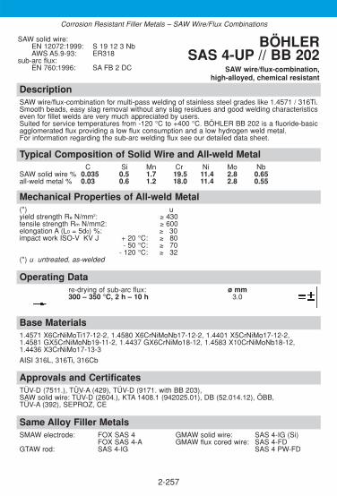
DescriptionSAW wire/flux-combination for multi-pass welding of stainless steel grades like 1.4571 / 316Ti.Smooth beads, easy slag removal without any slag residues and good welding characteristicseven for fillet welds are very much appreciated by users.Suited for service temperatures from -120 °C to +400 °C. BÖHLER BB 202 is a fluoride-basicagglomerated flux providing a low flux consumption and a low hydrogen weld metal. For information regarding the sub-arc welding flux see our detailed data sheet.
Approvals and CertificatesTÜV-D (7511.), TÜV-A (429), TÜV-D (9171. with BB 203), SAW solid wire: TÜV-D (2604.), KTA 1408.1 (942025.01), DB (52.014.12), ÖBB, TÜV-A (392), SEPROZ, CE
Base Materials1.4571 X6CrNiMoTi17-12-2, 1.4580 X6CrNiMoNb17-12-2, 1.4401 X5CrNiMo17-12-2,1.4581 GX5CrNiMoNb19-11-2, 1.4437 GX6CrNiMo18-12, 1.4583 X10CrNiMoNb18-12,1.4436 X3CrNiMo17-13-3
AISI 316L, 316Ti, 316Cb
SAW solid wire:EN 12072:1999: S 19 12 3 NbAWS A5.9-93: ER318
sub-arc flux:EN 760:1996: SA FB 2 DC
BÖHLER SAS 4-UP // BB 202
SAW wire/flux-combination,high-alloyed, chemical resistant
2-257
Same Alloy Filler Metals SMAW electrode: FOX SAS 4 GMAW solid wire: SAS 4-IG (Si)
FOX SAS 4-A GMAW flux cored wire: SAS 4-FDGTAW rod: SAS 4-IG SAS 4 PW-FD
Typical Composition of Solid Wire and All-weld MetalC Si Mn Cr Ni Mo Nb
SAW solid wire % 0.035 0.5 1.7 19.5 11.4 2.8 0.65all-weld metal % 0.03 0.6 1.2 18.0 11.4 2.8 0.55
Mechanical Properties of All-weld Metal(*) uyield strength Re N/mm2: ≥ 430tensile strength Rm N/mm2: ≥ 600elongation A (L0 = 5d0) %: ≥ 330impact work ISO-V KV J + 20 °C: ≥ 380
- 50 °C: ≥ 370- 120 °C: ≥ 332
(*) u untreated, as-welded
Operating Datare-drying of sub-arc flux: ø mm300 – 350 °C, 2 h – 10 h 3.0
Corrosion Resistant Filler Metals – SAW Wire/Flux Combinations
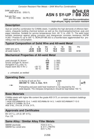
2-258
DescriptionSub-arc wire/flux combination for CrNiMo steels. It satisfies the high demands of offshore fabri-cators, shipyards building chemical tankers as well as the chemical/petrochemical, pulp andpaper industries. Suitable for service temperatures from -60 °C to +300 °C. The weld metalexhibits resistance against pitting corrosion and intergranular corrosion resistance (ASTMA 262 / Practice E) up to 300 °C. BÖHLER BB 202 is a fluoride-basic agglomerated flux pro-viding a low flux consumption.
Approvals and CertificatesBV (317 L), LR (D, BF 317L)Flux: CE
Same Alloy / Similar Alloy Filler MetalsSMAW electrode: FOX E 317 LGMAW flux cored wire: E 317 L PW-FD
E317 L-FD
Base MaterialsCrNiMo-steels with higher Mo-content like grade AISI 317L or corrosion resistant claddingson mild steels1.4434 X2CrNiMoN18-12-4, 1.4435 X2CrNiMo18-14-3, 1.4429 X2CrNiMoN17-13-31.4438 X 2 CrNiMo 18-15-4AISI 316L, 316 LN, 317LN, 317L
Operating Datare-drying of sub-arc flux: ø mm300-350 °C / min. 2, max. 10 h 3.0
4.0Preheating and post weld heat treatment is not required by the weld deposit. The interpass temperature should be kept below 150 °C.
Mechanical Properties of All-weld Metalu
yield strength Re N/mm2: 410 (≥ 350)tensile strength Rm N/mm2: 590 (≥ 550)elongation A (L0=5d0) %: 29 (≥ 25)impact work ISO-V KV J +20 °C: 58 (≥ 47)
-60 °C: 50 (≥ 32)
u untreated, as welded
Typical Composition of Solid Wire and All-weld MetalC Si Mn Cr Ni Mo FN
SAW wire wt-% ≤0.03 0.50 1.6 19.0 13.5 3.6all-weld metal % <0.03 0.60 1.2 18.5 13.4 3.5 4-12
SAW solid wire:AWS A5.9-93: ER317L
Sub-arc flux:EN 760:1996: SA FB 2 DC
BÖHLER ASN 5 SY-UP // BB 202
SAW wire/flux-combinationhigh-alloyed, highly corrosion resistant
Corrosion Resistant Filler Metals – SAW Wire/Flux Combinations
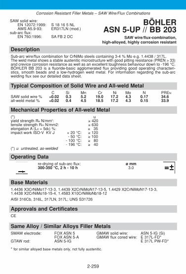
DescriptionSub-arc wire/flux combination for CrNiMo steels containing 3-4 % Mo e.g. 1.4438 / 317L.The weld metal shows a stable austenitic microstructure with good pitting resistance (PREN > 33)and crevice corrosion resistance as well as an excellent toughness behaviour down to -196 °C.BÖHLER BB 203 is a fluoride-basic agglomerated flux providing good operating characteri-stics, smooth beads and a low-hydrogen weld metal. For information regarding the sub-arcwelding flux see our detailed data sheet.
Approvals and CertificatesCE
Base Materials1.4436 X3CrNiMo17-13-3, 1.4439 X2CrNiMoN17-13-5, 1.4429 X2CrNiMoN17-13-3,1.4438 X2CrNiMo18-15-4, 1.4583 X10CrNiMoNb18-12
AISI 316Cb, 316L, 317LN, 317L; UNS S31726
SAW solid wire:EN 12072:1999: S 18 16 5 NLAWS A5.9-93: ER317LN (mod.)
sub-arc flux:EN 760:1996: SA FB 2 DC
BÖHLER ASN 5-UP // BB 203
SAW wire/flux-combination,high-alloyed, highly corrosion resistant
2-259
Same Alloy / Similar Alloys Filler Metals SMAW electrode: FOX ASN 5 GMAW solid wire: ASN 5-IG (Si)
FOX ASN 5-A GMAW flux cored wire: E 317L-FD*GTAW rod: ASN 5-IG E 317L PW-FD*
* for similar alloyed base metals only, not fully austenitic.
Typical Composition of Solid Wire and All-weld MetalC Si Mn Cr Ni Mo N PREN
SAW solid wire % ≤0.02 0.3 5.2 19.0 17.2 4.3 0.17 34.6all-weld metal % ≤0.02 0.4 4.5 18.5 17.2 4.3 0.15 33.9
Mechanical Properties of All-weld Metal(*) uyield strength Re N/mm2: ≥ 420tensile strength Rm N/mm2: ≥ 630elongation A (L0 = 5d0) %: ≥ 335impact work ISO-V KV J + 20 °C: ≥ 120
- 50 °C: ≥ 100- 100 °C: ≥ 380- 196 °C: ≥ 340
(*) u untreated, as-welded
Operating Datare-drying of sub-arc flux: ø mm300-350 °C, 2 h - 10 h 3.0
Corrosion Resistant Filler Metals – SAW Wire/Flux Combinations
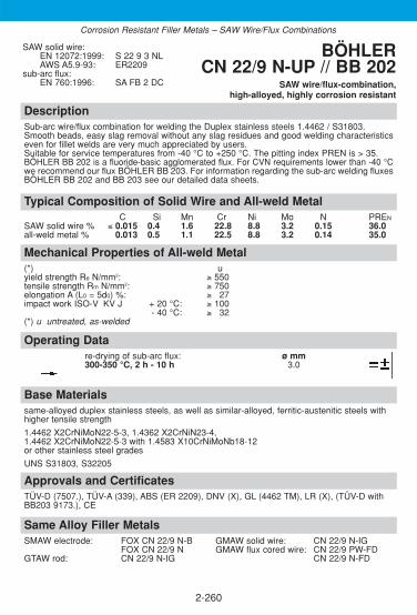
DescriptionSub-arc wire/flux combination for welding the Duplex stainless steels 1.4462 / S31803.Smooth beads, easy slag removal without any slag residues and good welding characteristicseven for fillet welds are very much appreciated by users.Suitable for service temperatures from -40 °C to +250 °C. The pitting index PREN is > 35.BÖHLER BB 202 is a fluoride-basic agglomerated flux. For CVN requirements lower than -40 °Cwe recommend our flux BÖHLER BB 203. For information regarding the sub-arc welding fluxesBÖHLER BB 202 and BB 203 see our detailed data sheets.
Approvals and CertificatesTÜV-D (7507.), TÜV-A (339), ABS (ER 2209), DNV (X), GL (4462 TM), LR (X), (TÜV-D withBB203 9173.), CE
Base Materialssame-alloyed duplex stainless steels, as well as similar-alloyed, ferritic-austenitic steels withhigher tensile strength
1.4462 X2CrNiMoN22-5-3, 1.4362 X2CrNiN23-4,1.4462 X2CrNiMoN22-5-3 with 1.4583 X10CrNiMoNb18-12 or other stainless steel grades
UNS S31803, S32205
SAW solid wire:EN 12072:1999: S 22 9 3 NLAWS A5.9-93: ER2209
sub-arc flux:EN 760:1996: SA FB 2 DC
BÖHLER CN 22/9 N-UP // BB 202
SAW wire/flux-combination,high-alloyed, highly corrosion resistant
2-260
Typical Composition of Solid Wire and All-weld MetalC Si Mn Cr Ni Mo N PREN
SAW solid wire % ≤ 0.015 0.4 1.6 22.8 8.8 3.2 0.15 36.0all-weld metal % 0.013 0.5 1.1 22.5 8.8 3.2 0.14 35.0
Mechanical Properties of All-weld Metal(*) uyield strength Re N/mm2: ≥ 550tensile strength Rm N/mm2: ≥ 750elongation A (L0 = 5d0) %: ≥ 327impact work ISO-V KV J + 20 °C: ≥ 100
- 40 °C: ≥ 032(*) u untreated, as-welded
Operating Datare-drying of sub-arc flux: ø mm300-350 °C, 2 h - 10 h 3.0
Same Alloy Filler Metals SMAW electrode: FOX CN 22/9 N-B GMAW solid wire: CN 22/9 N-IG
FOX CN 22/9 N GMAW flux cored wire: CN 22/9 PW-FDGTAW rod: CN 22/9 N-IG CN 22/9 N-FD
Corrosion Resistant Filler Metals – SAW Wire/Flux Combinations

2-261
Notes

2-262
Notes

2-263
2.7 Filler metals for Dissimilar Joints and Special Applications
ObjectivesThe materials used for welding engineering appear vast, confusing and com-plicated if one takes into consideration all the dissimilar weld joints that arepossible between the most varied types of steel. It is practically impossibleto record every individual combination of materials. Since this is the case,the queries received by our welding technicians help line very often refer tothe practical problems surrounding welding of dissimilar joints. The choice of filler metal must be emphasised as a crucial criterion. Thischoice must be made so that where possible the weld metal generated is nottoo hard, brittle and susceptible to cracks allowing for dilution with the diffe-rent parent metals. As a consequence of this, later sections of this manual set out general gro-und rules containing tips, recommendations and precautionary measures inthe form of broad guidelines which are to be considered when choosing fil-ler metals and creating a welding technology. However, ground rules such asthese may only be deemed as of value if they can be implemented in prac-tice with sufficient expertise and basic knowledge of metallurgy. This section describes filler metals that may be used for many different dis-similar welds or in the welding of problem steels.
Contents
OVERVIEW . . . . . . . . . . . . . . . . . . . . . . . . . . . . . . . . . . . . . . . . . . . . . . .264
SMAW COVERED ELECTRODES . . . . . . . . . . . . . . . . . . . . . . . . . . . . .266
GTAW RODS . . . . . . . . . . . . . . . . . . . . . . . . . . . . . . . . . . . . . . . . . . . . . .276
GMAW SOLID WIRES . . . . . . . . . . . . . . . . . . . . . . . . . . . . . . . . . . . . . . .279
GMAW METAL CORED AND FLUX-CORED WIRES . . . . . . . . . . . . . . .282
SAW WIRE/FLUX-COMBINATIONS . . . . . . . . . . . . . . . . . . . . . . . . . . . .290
◆
◆
Product Information

2-264
Overview – Standard Classifications
Böhler EN / ENISO AWSSMAW covered electrodesFOX A 7 1600: E 18 8 Mn B 2 2 A5.4-92: E307-15(mod.)FOX A 7-A 1600: E Z 18 9 MnMo R 3 2 A5.4-92: E307-16(mod.)FOX CN 19/9 M 1600: E 20 10 3 R 3 2 A5.4-92: E308Mo-17(mod.) FOX CN 23/12-A 1600: E 23 12 L R 3 2 A5.4-92: E309L-17FOX CN 23/12 Mo-A 1600: E 23 12 2 L R 3 2 A5.4-92: E309MoL-17(mod.)FOX CN 24/13 1600: E 23 12 B 2 2 A5.4-92: E309L-15FOX CN 24/13 Nb 1600: E 23 12 Nb B 2 2 A5.4-92: E309Cb-15FOX CN 29/9 1600: E 29 9 R 1 2 A5.4-92: E312-16(mod.)FOX CN 29/9-A 1600: E 29 9 R 3 2 A5.4-92: E312-17(mod.)FOX RDA
GTAW rodsA 7 CN-IG 12072: W 18 8 Mn A5.9-93: ER307(mod.)CN 19/9 M-IG 12072: W 20 10 3 A5.9-93: ER308Mo(mod.) CN 23/12-IG 12072: W 23 12 L A5.9-93: ER309L
GMAW solid wiresA 7-IG 12072: G 18 8 Mn A5.9-93: ER307(mod.)CN 19/9 M-IG 12072: G 20 10 3 A5.9-93: ER308Mo(mod.) CN 23/12-IG 12072: G 23 12 L A5.9-93: ER309L
GMAW metal cored and flux-cored wiresA 7-MC 17633-A: T 18 8 Mn MM1 A5.9-93: EC307(mod.)CN 23/12-MC 17633-A: T 23 12 L MM1 A5.9-93: E309LA 7-FD 17633-A: T 18 8 Mn R M 3 A5.22-95: E307T0-G
T 18 8 Mn R C 3A 7 PW-FD 17633-A: T 18 8 Mn P M 2 A5.22-95: E307T1-G
T 18 8 Mn P C 2CN 23/12-FD 17633-A: T 23 12 L R M 3 A5.22-95: E309LT0-4
T 23 12 L R C 3 E309LT0-1CN 23/12 PW-FD 17633-A: T 23 12 L P M 1 A5.22-95: E309LT1-4
T 23 12 L P C 1 E309LT1-1CN 23/12 Mo-FD 17633-A: T 23 12 2 L R M 3 A5.22-95: E309LMoT0-4
T 23 12 2 L R C 3 E309LMoT0-1CN 23/12 Mo PW-FD 17633-A: T 23 12 2 L P M 1 A5.22-95: E309LMoT1-4
T 23 12 2 L P C 1 E309LMoT1-1
SAW wire/flux-combinationsA 7CN-UP 12072: S 18 8 Mn A5.9-93: ER307(mod.)A 7CN-UP/BB 203 12072/760: S 18 8 Mn / SA FB 2 ER307(mod.)CN 23/12-UP 12072: S 23 12 L A5.9-93: ER309LCN 23/12-UP/BB 202 12072/760: S 23 12 L / SA FB 2 ER309L
◆
Dissimilar welds and special applications

Overview – Typical Chemical Composition
Böhler C Si Mn Cr Ni Mo NbSMAW covered electrodesFOX A 7 0.10 0.7 6.5 18.8 8.8 –FOX A 7-A 0.10 1.5 4.0 19.5 8.5 0.7FOX CN 19/9 M 0.04 0.8 1.0 20.2 10.3 3.2FOX CN 23/12-A 0.02 0.7 0.8 23.2 12.5 –FOX CN 23/12 Mo-A 0.02 0.7 0.8 23.0 12.5 2.7FOX CN 24/13 0.03 0.3 1.3 23.8 12.0FOX CN 24/13 Nb 0.03 0.4 1.0 24.2 12.5 – 0.85FOX CN 29/9 0.11 1.0 0.7 29.0 10.2FOX CN 29/9-A 0.11 0.9 0.7 28.8 9.5FOX RDA – – – – – –
GTAW rodsA 7 CN-IG 0.08 0.8 7.0 19.2 9.0CN 19/9 M-IG 0.06 0.7 1.3 20.0 10.0 3.3CN 23/12-IG ≤ 0.02 0.5 1.7 24.0 13.2
GMAW solid wiresA 7-IG 0.08 0.9 7.0 19.2 9.0CN 19/9 M-IG 0.06 0.7 1.3 20.0 10.0 3.3CN 23/12-IG ≤ 0.02 0.5 1.7 24.0 13.2
GMAW metal cored and flux-cored wiresA 7-MC 0.1 0.6 6.3 18.8 9.2CN 23/12-MC ≤0.03 0.6 1.4 23.0 12.5A 7-FD 0.1 0.7 6.5 18.5 8.8
A 7 PW-FD 0.1 0.8 7.0 18.8 9.0
CN 23/12-FD 0.03 0.7 1.4 23.0 12.5
CN 23/12 PW-FD 0.03 0.7 1.4 23.0 12.5
CN 23/12 Mo-FD 0.03 0.6 1.4 23.0 12.5 2.7
CN 23/12 Mo PW-FD 0.03 0.7 1.4 23.0 12.5 2.7
SAW wire/flux-combinationsA 7CN-UP 0.08 0.9 7.0 19.2 9.0A 7CN-UP/BB 203 0.06 0.8 6.0 18.7 9.0CN 23/12-UP ≤0.02 0.5 1.8 24.0 13.2CN 23/12-UP/BB 202 0.015 0.6 1.3 23.5 13.2
◆
2-265
Dissimilar welds and special applications

DescriptionBasic electrode, for joint welding of dissimilar joints, problem steels and for repair and mainte-nance. Very popular electrode for numerous applications. The weld metal offers exceptionallyhigh ductility and elongation together with outstanding crack resistance. There is no fear ofembrittlement when operating down to service temperatures of -110 °C or above +500 °C. Thescaling resistance goes up to +850 °C. When working at service temperatures above +650 °Cplease contact the supplier. The weld metal can be post weld heat treated without any pro-blems. The deposit will work harden and offers good resistance against cavitation. Ductility isgood even after high dilution when welding problem steels or when subjected to thermal shockor scaling. An excellent alloy providing cost effective performance.
Approvals and CertificatesTÜV-D (06786.), DNV (E 18 8 MnB), GL (4370), LTSS, VUZ, PRS (4370), SEPROZ, CE
Base MaterialsFor fabrication, repair and maintenance!Dissimilar joints, tough buffer and intermediate layers prior to hardfacing, 14 % manganesesteels, 13 - 17 % chromium heat resistant steels up to +850 °C, armour plates, high carbonand quenched & tempered steels, surfacing of gears, valves, turbine blades etc.
Typical Composition of All-weld MetalC Si Mn Cr Ni
wt-% 0.1 0.7 6.5 18.8 8.8
EN 1600:1997: E 18 8 Mn B 2 2AWS A5.4-92: E307-15 (mod.) BÖHLER
FOX A 7 SMAW basic electrode, high-alloyed,
special applications
2-266
Same Alloy Filler Metals SMAW electrode: FOX A 7-A Metal cored wire: A 7-MCGTAW rod: A 7CN-IG GMAW flux cored wire: A 7-FD, A 7 PW-FDGMAW solid wire: A 7-IG SAW combination: A 7CN-UP/BB 203
Mechanical Properties of All-weld Metal(*) uyield strength Re N/mm2: 460 (≥ 390)tensile strength Rm N/mm2: 660 (≥ 620)elongation A (L0 = 5d0) %: 38 (≥ 335)impact work ISO-V KV J + 20 °C: 90 (≥ 380)
- 110 °C: (≥ 332)(*) u untreated, as-welded
Operating Datare-drying if necessary: ø mm L mm amps A120 - 200 °C, min. 2 h 2.5 300 55 - 175electrode identification: 3.2 350 80 - 100FOX A 7 E 18 8 Mn B 4.0 350 100 - 130
5.0 450 140 - 1706.0 450 160 - 200
Preheating and interpass temperature as required by the base metal.
Dissimilar Joints and Special Applications – SMAW Covered Electrodes

DescriptionRutile basic electrode, for joint welding of dissimilar joints, problem steels and for repair andmaintenance. Very popular electrode for numerous applications. The weld metal offers excep-tionally high ductility and elongation together with outstanding crack resistance. There is no fearof embrittlement when operating down to service temperatures of -100 °C or above +500 °C.The scaling resistance goes up to +850 °C. When working at service temperatures above +650 °C please contact the supplier. The weld metal can be post weld heat treated without anyproblems. The deposit will work harden and offers good resistance against cavitation. Ductilityis good even after high dilution when welding problem steels or when subjected to thermalshock or scaling. An excellent alloy providing cost effective performance. BÖHLER FOX A 7-Ais suitable for both AC and DC.
Approvals and CertificatesTÜV-D (09101.), SEPROZ, CE
Base MaterialsFor fabrication, repair and maintenance!Dissimilar joints, tough buffer and intermediate layers prior to hardfacing, 14 % manganesesteels, 13 - 17 % chromium heat resistant steels up to +850 °C, armour plates, high carbonand quenched & tempered steels, surfacing of gears, valves, turbine blades etc.
Typical Composition of All-weld MetalC Si Mn Cr Ni Mo
wt-% 0.10 1.5 4.0 19.5 8.5 0.7
EN 1600:1997: E Z18 9 MnMo R 3 2AWS A5.4-92: E307-16 (mod.) BÖHLER FOX A 7-A
SMAW rutile basic electrode, high-alloyed,special applications
2-267
Mechanical Properties of All-weld Metal(*) uyield strength Re N/mm2: 520 (≥ 390)tensile strength Rm N/mm2: 720 (≥ 620)elongation A (L0 = 5d0) %: 35 (≥ 330)impact work ISO-V KV J + 20 °C: 75 (≥ 347)
- 100 °C: (≥ 332)(*) u untreated, as-welded
Operating Datare-drying if necessary: ø mm L mm amps A120 - 200 °C, min. 2 h 2.5 350 60 - 180electrode identification: 3.2 350 80 - 110FOX A 7-A E Z 18 9 MnMo R 4.0 350 110 - 140
5.0 450 140 - 170Preheating and interpass temperature as required by the base metal.
Same Alloy Filler Metals SMAW electrode: FOX A 7 Metal cored wire: A 7-MCGTAW rod: A 7CN-IG GMAW flux cored wire: A 7-FD, A 7 PW-FDGMAW solid wire: A 7-IG SAW combination: A 7CN-UP/BB203
Dissimilar Joints and Special Applications – SMAW Covered Electrodes

DescriptionRutile electrode of type E 20 10 3 / 308Mo. This electrode is designed for dissimilar joints andweld cladding.BÖHLER FOX CN 19/9 M offers a lower chromium and ferrite content than a 309MoL welddeposit with the result that carbon diffusion and Cr-carbide formation is reduced after post weldheat treatment and lower ferrite contents can be achieved in the second layer of 316Lsurfacing. Suitable for service temperatures from -80 °C to +300 °C. Safety against formation of porositydue to the moisture resistant coating.
Approvals and CertificatesTÜV-D (1086.), DB (30.014.03), ÖBB, ABS (Cr18/20, Ni8/10Mo), GL (4431), LR (V4-P12), SEPROZ, CE
Base Materialshigh-strength, mild steels and low-alloyed constructional steels, QT-steels and armour platesamong themselves or among each other; non-alloy as well as alloyed boiler or constructionalsteels with high-alloy stainless Cr- and Cr-Ni-steels; austenitic manganese steels similar anddissimilar.
Typical Composition of All-weld MetalC Si Mn Cr Ni Mo
wt-% 0.04 0.8 1.0 20.2 10.3 3.2
EN 1600:1997: E 20 10 3 R 3 2AWS A5.4-92 E308Mo-17 (mod.) BÖHLER FOX CN 19/9 M
SMAW rutile electrode, high-alloyed,special applications
2-268
Same Alloy Filler Metals GTAW rod: CN 19/9 M-IG GMAW solid wire: CN 19/9 M-IG
Mechanical Properties of All-weld Metal(*) uyield strength Re N/mm2: 520 (≥ 450)tensile strength Rm N/mm2: 700 (≥ 650)elongation A (L0 = 5d0) %: 30 (≥ 325)impact work ISO-V KV J + 20 °C: 70 (≥ 355)
- 80 °C: (≥ 332)(*) u untreated, as-welded
Operating Datare-drying if necessary: ø mm L mm amps A250 - 300 °C, min. 2 h 2.5 250 50 - 185electrode identification: 3.2 350 75 - 115FOX CN 19 9 M E 20 10 3 R 4.0 350 110 - 160
5.0 450 160 - 200 Preheating and interpass temperature as required by the base metal.
Dissimilar Joints and Special Applications – SMAW Covered Electrodes
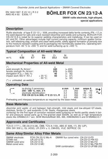
DescriptionRutile electrode of type E 23 12 L / 309L providing increased delta ferrite contents (FN ~17) inthe weld deposit for safe and crack resistant dissimilar joint welds and surfacing. BÖHLER FOXCN 23/12-A is noted for its superior welding characteristics and metallurgy. It can be used onAC and DC. Other advantages include high current carrying capacity, minimum spatter forma-tion, self releasing slag, smooth and clean weld profile, safety against formation of porosity dueto the moisture resistant coating and its packaging into hermetically sealed tins. Operating tem-perature from -60 °C to +300 °C and for weld surfacing up to +400 °C.
Approvals and CertificatesTÜV-D (1771.), DB (30.014.08), ÖBB, TÜV-A (130), ABS (E 309L-17), BV (UP), DNV (NV 309 L), GL (4332), LR (DXV u. 0, CMnSS), VUZ, SEPROZ, CE
Base Materialsdissimilar joint welds: of and between high-strength, mild steels and low-alloyed QT-steels,stainless, ferritic Cr- and austenitic Cr-Ni- steels, manganese steelssurfacing: for the first layer of corrosion resistant weld surfacing on ferritic-perlitic steels in boi-ler and pressure vessel parts up to fine-grained steel S500N, as well as of high temperaturesteels like 22NiMoCr4-7 acc. SEW-Werkstoffblatt 365, 366, 20MnMoNi5-5 and G18NiMoCr3-7
Typical Composition of All-weld MetalC Si Mn Cr Ni
wt-% 0.02 0.7 0.8 23.2 12.5
EN 1600:1997: E 23 12 L R 3 2AWS A5.4-92: E309L-17 BÖHLER FOX CN 23/12-A
SMAW rutile electrode, high-alloyed,special applications
2-269
Same Alloy/Similar Alloy Filler Metals SMAW electrode: FOX CN 23/12 Mo-A GMAW flux cored wire: CN 23/12-FDGTAW rod: CN 23/12-IG CN 23/12 PW-FDGMAW solid wire: CN 23/12-IG CN 23/12 Mo-FDMetal cored wire: CN 23/12-MC CN 23/12 Mo PW-FD
SAW combination: CN 23/12-UP/BB 202
Mechanical Properties of All-weld Metal(*) uyield strength Re N/mm2: 440 (≥ 400)tensile strength Rm N/mm2: 570 (≥ 550)elongation A (L0 = 5d0) %: 40 (≥ 330)impact work ISO-V KV J + 20 °C: 60 (≥ 347)
- 60 °C: (≥ 332)(*) u untreated, as-welded
Operating Datare-drying if necessary: ø mm L mm amps A250 - 300 °C, min. 2 h 2.5 350 60 - 180electrode identification: 3.2 350 80 - 110FOX CN 23/12-A 309L-17 E 23 12 L R 4.0 350 110 - 140
5.0 450 140 - 180 Preheating and interpass temperature as required by the base metal.
Dissimilar Joints and Special Applications – SMAW Covered Electrodes

DescriptionRutile electrode of type E 23 12 2 L / 309MoL providing increased delta ferrite contents (FN ~20) in the weld deposit for safe and crack resistant dissimilar joint welds as well as surfacing or root passes of clad steel. BÖHLER FOX CN 23/12 Mo-A is noted for its superiorwelding characteristics and metallurgy. It can be used on AC and DC. Other advantages include high current carrying capacity, minimum spatter formation, self releasing slag, smoothand clean weld profile, safety against formation of porosity due to the moisture resistant coating and its packaging into hermetically sealed tins. Operating temperature from -10 °C to +300 °C and for weld surfacing (1st layer) up to +400 °C.
Approvals and CertificatesTÜV-D (1362.), TÜV-A (34), ABS (E 309 Mo), RINA (309Mo), DNV (309MoL), LR (DXV u. 0,CMnSS), BV (309 Mo), LTSS, VUZ, SEPROZ, CE
Base Materialsdissimilar joint welds:mild steels and low-alloyed constructional and QT-steels among themselves or among eachother; unalloyed as well as low-alloyed boiler or constructional steels with stainless Cr-, CrNi-and CrNiMo-steels; ferritic-austenitic joint welds in boiler and pressure vessel parts.weld surfacing: for the first layer of corrosion resistant surfacing on P235GH, P265GH, S255N,P295GH, S355N - S500N; for the first layer of corrosion resistant weld surfacing on high tem-perature quenched and tempered fine-grained steels acc. AD-Merkblatt HPO, class 3.
Typical Composition of All-weld MetalC Si Mn Cr Ni Mo
wt-% 0.02 0.7 0.8 23.0 12.5 2.7
EN 1600:1997: E 23 12 2 L R 3 2AWS A5.4-92: E309MoL-17 (mod.) BÖHLER
FOX CN 23/12 Mo-ASMAW rutile electrode, high-alloyed,
special applications
2-270
Same Alloy/Similar Alloy Filler Metals SMAW electrode: FOX CN 23/12-A GMAW flux cored wire: CN 23/12-FDGTAW rod: CN 23/12-IG CN 23/12 PW-FDGMAW solid wire: CN 23/12-IG CN 23/12 Mo-FDMetal cored wire: CN 23/12-MC CN 23/12 Mo PW-FD
SAW combination: CN 23/12-UP/BB 202
Mechanical Properties of All-weld Metal(*) uyield strength Re N/mm2: 580 (≥ 490)tensile strength Rm N/mm2: 720 (≥ 630)elongation A (L0 = 5d0) %: 27 (≥ 325)impact work ISO-V KV J + 20 °C: 55 (≥ 347)
- 20 °C: 345 (≥ 332)(*) u untreated, as-welded
Operating Datare-drying if necessary: ø mm L mm amps A250 - 300 °C, min. 2 h 2.0 300 45 - 160electrode identification: 2.5 350 60 - 180FOX CN 23/12 Mo-A E 23 12 2 L R 3.2 350 80 - 120
4.0 350 100 - 1605.0 450 140 - 220
Preheating and interpass temperature as required by the base metal.
Dissimilar Joints and Special Applications – SMAW Covered Electrodes

2-271
DescriptionBasic electrode with controlled alloying elements to meet the metallurgical requirements of buffer layers. Stringer bead technique is recommended. Normally used in combination with different corrosion resistant surfacing, depending on the base material also with an additionalPWHT. For service temperatures up to +400 °C.
Approvals and Certificates–
Base MaterialsFor buffer layers on weldable unalloyed, high tensile, high temperature or alloyed base metals.
Operating Datare-drying: if necessary: ø mm L mm amps A300-350 °C, min. 2 h 3.2 350 95-115electrode identification: 4.0 350 120-145FOX CN 24/13 309 L-15 E 23 12 L BPreheating and interpass temperature acc. the base materials.
Mechanical Properties of All-weld Metal(*) uyield strength Re N/mm2: 430 (≥ 320)tensile strength Rm N/mm2: 570 (≥ 520)elongation A (L0=5d0) %: 35 (≥ 30)impact work ISO-V KV J +20 °C: 85 (≥ 47)
(*) u untreated, as-welded
Typical Composition of All-weld MetalC Si Mn Cr Ni
wt-% 0.03 0.3 1.3 23.8 12.0
EN 1600:1997: E 23 12 L B 2 2AWS A5.4-92: E309L-15 BÖHLER
FOX CN 24/13 SMAW basic electrode for special applications
Dissimilar Joints and Special Applications – SMAW Covered Electrodes

2-272
DescriptionBasic electrode with controlled alloying elements to meet the metallurgical requirements of buffer layers. Excellent welding properties, stable arc, well detaching slag without residuals.Stringer bead technique is recommended. Normally used in combination with different corrosion resistant surfacing, depending on the base material also with an additional PWHT. For service temperatures up to +400 °C.
Approvals and CertificatesTÜV-D (00141.), CE
Base MaterialsFor buffer layers on weldable unalloyed, high tensile, high temperature or alloyed base metals.
Operating Datare-drying: if necessary ø mm L mm amps A300-350 °C, min. 2 h 3.2 350 195-115electrode identification: 4.0 350 120-145FOX CN 24/13 Nb 309 Cb-15 E 23/12 Nb B
Preheating and interpass temperature acc. the base materials.
Mechanical Properties of All-weld Metal(*) uyield strength Re N/mm2: 505 (≥ 350)tensile strength Rm N/mm2: 690 (≥ 550)elongation A (L0=5d0) %: 25 (≥ 22)impact work ISO-V KV J +20 °C: 95 (≥ 47)
-10 °C: 85
(*) u untreated, as-welded
Typical Chemical Composition of All-weld MetalC Si Mn Cr Ni Nb
wt-% 0.03 0.4 1.0 24.2 12.5 0.85
EN 1600:1997: E 23 12 Nb B 2 2AWS A5.4-92: E309Cb-15 BÖHLER
FOX CN 24/13 Nb SMAW basic electrode for special applications
Dissimilar Joints and Special Applications – SMAW Covered Electrodes
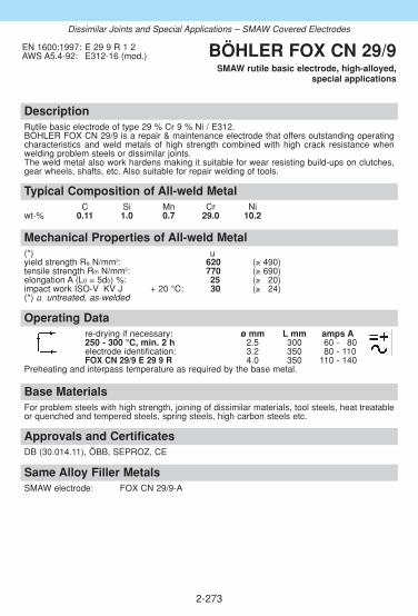
DescriptionRutile basic electrode of type 29 % Cr 9 % Ni / E312.BÖHLER FOX CN 29/9 is a repair & maintenance electrode that offers outstanding operatingcharacteristics and weld metals of high strength combined with high crack resistance whenwelding problem steels or dissimilar joints.The weld metal also work hardens making it suitable for wear resisting build-ups on clutches,gear wheels, shafts, etc. Also suitable for repair welding of tools.
Approvals and CertificatesDB (30.014.11), ÖBB, SEPROZ, CE
Base MaterialsFor problem steels with high strength, joining of dissimilar materials, tool steels, heat treatableor quenched and tempered steels, spring steels, high carbon steels etc.
Typical Composition of All-weld MetalC Si Mn Cr Ni
wt-% 0.11 1.0 0.7 29.0 10.2
EN 1600:1997: E 29 9 R 1 2AWS A5.4-92: E312-16 (mod.) BÖHLER FOX CN 29/9
SMAW rutile basic electrode, high-alloyed,special applications
2-273
Same Alloy Filler Metals SMAW electrode: FOX CN 29/9-A
Mechanical Properties of All-weld Metal(*) uyield strength Re N/mm2: 620 (≥ 490)tensile strength Rm N/mm2: 770 (≥ 690)elongation A (L0 = 5d0) %: 25 (≥ 320)impact work ISO-V KV J + 20 °C: 30 (≥ 324)(*) u untreated, as-welded
Operating Datare-drying if necessary: ø mm L mm amps A250 - 300 °C, min. 2 h 2.5 300 60 - 180electrode identification: 3.2 350 80 - 110FOX CN 29/9 E 29 9 R 4.0 350 110 - 140
Preheating and interpass temperature as required by the base metal.
Dissimilar Joints and Special Applications – SMAW Covered Electrodes

DescriptionRutile electrode of type 29 % Cr 9 % Ni / E312.BÖHLER FOX CN 29/9-A is a repair & maintenance electrode that offers outstanding operatingcharacteristics on both DC and AC and weld metals of high strength combined with high crackresistance when welding problem steels or dissimilar joints.The weld metal also work hardens making it suitable for wear resisting build-ups on clutches,gear wheels, shafts, etc. Also suitable for repair welding of tools.
Approvals and CertificatesDB (30.014.16, 20.014.07), ÖBB, VUZ, CE
Base MaterialsFor problem steels with high strength, joining of dissimilar materials, tool steels, heat treatableor quenched and tempered steels, spring steels, high carbon steels etc.
Typical Composition of All-weld MetalC Si Mn Cr Ni
wt-% 0.11 0.9 0.7 28.8 9.5
EN 1600:1997: E 29 9 R 3 2AWS A5.4-92: E312-17 (mod.) BÖHLER FOX CN 29/9-A
SMAW rutile electrode, high-alloyed,special applications
2-274
Same Alloy Filler Metals SMAW electrode: FOX CN 29/9
Mechanical Properties of All-weld Metal(*) uyield strength Re N/mm2: 650 (≥ 490)tensile strength Rm N/mm2: 790 (≥ 670)elongation A (L0 = 5d0) %: 24 (≥ 320)impact work ISO-V KV J + 20 °C: 30 (≥ 324)(*) u untreated, as-welded
Operating Datare-drying if necessary: ø mm L mm amps A250 - 300 °C, min. 2 h 2.5 300 60 - 180electrode identification: 3.2 350 80 - 110FOX CN 29/9-A E 29 9 R 4.0 350 110 - 140
5.0 450 140 - 180Preheating and interpass temperature as required by the base metal.
Dissimilar Joints and Special Applications – SMAW Covered Electrodes

DescriptionSpecial electrode for welding of rule die steel.
This electrode provides easy striking and re-striking, excellent welding characteristics as wellas very ductile and crack resistant joints welds on rule die steel.
Base MaterialsRule die steels
BÖHLER FOX RDASMAW covered electrode, high-alloyed,
special applications
2-275
Operating Datare-drying if necessary: ø mm L mm amps A120 - 200 °C, min. 2 h 1.5 250 40 - 60electrode identification: 2.0 250 50 - 80FOX RDA
Dissimilar Joints and Special Applications – SMAW Covered Electrodes
Approvals and Certificates–

DescriptionGTAW rod of type W 18 8 Mn / ER307 for numerous applications. The weld metal offers exceptionally high ductility and elongation together with outstandingcrack resistance. There is no fear of embrittlement when operating down to service temperatu-res of -110 °C or above +500 °C. The scaling resistance goes up to +850 °C. When working atservice temperatures above +650 °C please contact the supplier.The weld metal can be post weld heat treated without any problems. The deposit will work harden and offers good resistance against cavitation. Ductility is good even after high dilutionwhen welding problem steels or when subjected to thermal shock or scaling. An excellent alloyproviding cost effective performance.Very good welding and wetting characteristics.
Approvals and CertificatesTÜV-D (00023.), DNV (X), GL (4370), CE
Base MaterialsFor fabrication, repair and maintenance!Dissimilar joints, tough buffer and intermediate layers prior to hardfacing, 14 % manganesesteels, 13 - 17 % chromium heat resistant steels up to +850 °C, armour plates, high carbon andquenched & tempered steels, surfacing of gears, valves, turbine blades etc.
Operating Datashielding gas: 100 % Argon ø mmrod marking: 1.6
front: W 18 8 Mn 2.0back: 1.4370 2.4
3.0Preheating and interpass temperature as required by the base metal.
Typical Composition of Welding RodC Si Mn Cr Ni
wt-% 0.08 0.8 7.0 19.2 9.0
EN 12072:1999: W 18 8 MnAWS A5.9-93: ER307 (mod.)W.Nr.: 1.4370
BÖHLER A 7 CN-IGGTAW rod, high-alloyed,
special applications
2-276
Same Alloy Filler Metals SMAW electrode: FOX A 7 Metal cored wire: A 7-MC
FOX A 7-A GMAW flux cored wire: A 7-FD, A 7 PW-FDGMAW solid wire: A 7-IG SAW combination: A 7CN-UP/BB 203
Mechanical Properties of All-weld Metal(*) uyield strength Re N/mm2: 460 (≥ 450)tensile strength Rm N/mm2: 660 (≥ 620)elongation A (L0 = 5d0) %: 38 (≥ 335)impact work ISO-V KV J + 20 °C: 120 (≥ 100)
- 110 °C: (≥ 332)(*) u untreated, as-welded – shielding gas Argon
Dissimilar Welds and Special Applications – GTAW Rods

DescriptionGTAW rod of type W 20 10 3 / 308Mo. This rod is designed for dissimilar joints and weld cladding. BÖHLER CN 19/9 M-IG offers a lower chromium and ferrite content than a 309L welddeposit with the result that carbon diffusion and Cr-carbide formation is reduced after post weldheat treatment and lower ferrite contents can be achieved in the second layer of 316Lsurfacing. Suitable for service temperatures from -80 °C to +300 °C.Very good welding and wetting characteristics.
Approvals and CertificatesTÜV-D (0427.), DNV (308Mo), CE
Base Materialshigh-strength, mild steels and low-alloyed constructional steels, QT-steels and armour platesamong themselves or among each other; non-alloy as well as alloyed boiler or constructionalsteels with high-alloy stainless Cr- and Cr-Ni-steels; austenitic manganese steels similar anddissimilar.
Operating Datashielding gas: 100 % Argon ø mmrod marking: 1.6
front: W 20 10 3 2.0back: 1.4431 2.4
Preheating and interpass temperature as required by the base metal.
Typical Composition of Welding RodC Si Mn Cr Ni Mo
wt-% 0.06 0.7 1.3 20.0 10.0 3.3
EN 12072:1999: W 20 10 3AWS A5.9-93: ER308Mo (mod.)W.Nr.: 1.4431
BÖHLER CN 19/9 M-IGGTAW rod, high-alloyed,
special applications
2-277
Same Alloy Filler Metals SMAW electrode: FOX CN 19/9 M GMAW solid wire: CN 19/9 M-IG
Mechanical Properties of All-weld Metal(*) uyield strength Re N/mm2: 550 (≥ 470)tensile strength Rm N/mm2: 750 (≥ 670)elongation A (L0 = 5d0) %: 35 (≥ 330)impact work ISO-V KV J + 20 °C: 150 (≥ 380)
- 80 °C: (≥ 332)(*) u untreated, as-welded – shielding gas Argon
Dissimilar Welds and Special Applications – GTAW Rods
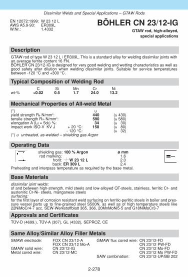
DescriptionGTAW rod of type W 23 12 L / ER309L. This is a standard alloy for welding dissimilar joints withan average ferrite content 16 FN.BÖHLER CN 23/12-IG is designed for very good welding and wetting characteristics as well asgood safety after dilution when welding dissimilar joints. Suitable for service temperaturesbetween -120 °C and +300 °C.
Approvals and CertificatesTÜV-D (4699.), TÜV-A (307), GL (4332), SEPROZ, CE
Base Materialsdissimilar joint welds:of and between high-strength, mild steels and low-alloyed QT-steels, stainless, ferritic Cr- andaustenitic Cr-Ni- steels, manganese steelssurfacing:for the first layer of corrosion resistant weld surfacing on ferritic-perlitic steels in boiler and pres-sure vessel parts up to fine-grained steel S500N, as well as of high temperature steels like22NiMoCr4-7 acc. SEW-Werkstoffblatt 365, 366, 20MnMoNi5-5 and G18NiMoCr3-7
Operating Datashielding gas: 100 % Argon ø mmrod marking: 1.6
front: W 23 12 L 2.0back: ER 309 L 2.4
Preheating and interpass temperature as required by the base metal.
Typical Composition of Welding RodC Si Mn Cr Ni
wt-% ≤0.02 0.5 1.7 24.0 13.2
EN 12072:1999: W 23 12 LAWS A5.9-93: ER309LW.Nr.: 1.4332
BÖHLER CN 23/12-IGGTAW rod, high-alloyed,
special applications
2-278
Same Alloy/Similar Alloy Filler Metals SMAW electrode: FOX CN 23/12-A GMAW flux cored wire: CN 23/12-FD
FOX CN 23/12 Mo-A CN 23/12 PW-FDGMAW solid wire: CN 23/12-IG CN 23/12 Mo-FDMetal cored wire: CN 23/12-MC CN 23/12 Mo PW-FD
SAW combination: CN 23/12-UP/BB 202
Mechanical Properties of All-weld Metal(*) uyield strength Re N/mm2: 440 (≥ 430)tensile strength Rm N/mm2: 590 (≥ 580)elongation A (L0 = 5d0) %: 34 (≥ 330)impact work ISO-V KV J + 20 °C: 150 (≥ 380)
- 120 °C: (≥ 332)(*) u untreated, as-welded – shielding gas Argon
Dissimilar Welds and Special Applications – GTAW Rods

DescriptionGMAW wire of type G 18 8 Mn / ER307 for numerous applications.The weld metal offers exceptionally high ductility and elongation together with outstandingcrack resistance. There is no fear of embrittlement when operating down to service temperatu-res of -110 °C or above +500 °C. The scaling resistance goes up to +850 °C. When working atservice temperatures above +650 °C please contact the supplier.The weld metal can be post weld heat treated without any problems. The deposit will workharden and offers good resistance against cavitation. Ductility is good even after high dilutionwhen welding problem steels or when subjected to thermal shock or scaling. An excellent alloy providing cost effective performance. Very good feeding, welding and wetting characteristics.
Approvals and CertificatesTÜV-D (06632.), DB (43.014.13), ÖBB, SEPROZ, CE
Base MaterialsFor fabrication, repair and maintenance!Dissimilar joints, tough buffer and intermediate layers prior to hardfacing, 14 % manganesesteels, 13 - 17 % chromium heat resistant steels up to +850 °C, armour plates, high carbon andquenched & tempered steels, surfacing of gears, valves, turbine blades etc.
Operating Datashielding gas: ø mmArgon + max. 2.5 % CO2 0.8
1.01.2
Preheating and interpass temperature 1.6as required by the base metal.
Typical Composition of Solid WireC Si Mn Cr Ni
wt-% 0.08 0.9 7.0 19.2 9.0
EN 12072:1999: G 18 8 MnAWS A5.9-93: ER307 (mod.)W.Nr.: 1.4370
BÖHLER A 7-IGGMAW solid wire, high-alloyed,
special applications
2-279
Mechanical Properties of All-weld Metal(*) uyield strength Re N/mm2: 430 (≥ 370)tensile strength Rm N/mm2: 640 (≥ 600)elongation A (L0 = 5d0) %: 36 (≥ 335)impact work ISO-V KV J + 20 °C: 110 (≥ 100)
- 110 °C: (≥ 332)(*) u untreated, as-welded – shielding gas Argon + max. 2.5 % CO2
Same Alloy Filler Metals SMAW electrode: FOX A 7 Metal cored wire: A 7-MC
FOX A 7-A GMAW flux cored wire: A 7-FD, A 7 PW-FDGTAW rod: A 7CN-IG SAW combination: A 7CN-UP/BB 203
Dissimilar Joints and Special Applications – GMAW Solid Wires

DescriptionGMAW wire of type G 20 10 3 / (308Mo). This wire is designed for dissimilar joints and weld cladding.BÖHLER CN 19/9 M-IG offers a lower chromium and ferrite content than a 309L weld depositwith the result that carbon diffusion and Cr-carbide formation is reduced after post weld heattreatment and lower ferrite contents can be achieved in the second layer of 316L surfacing.Suitable for service temperatures from -60 °C to +300 °C.
Approvals and CertificatesTÜV-D (1087.), DB (43.014.10), ÖBB, DNV (308Mo), CE
Base Materialshigh-strength, mild steels and low-alloyed constructional steels, QT-steels and armour platesamong themselves or among each other; non-alloy as well as alloyed boiler or constructionalsteels with high-alloy stainless Cr- and Cr-Ni-steels; austenitic manganese steels similar anddissimilar.
Operating Datashielding gases: ø mmArgon + max. 2.5 % CO2 1.0Argon + max. 1.0 % O2 1.2
Preheating and interpass temperature as required by the base metal.
Typical Composition of Solid WireC Si Mn Cr Ni Mo
wt-% 0.06 0.7 1.3 20.0 10.0 3.3
EN 12072:1999: G 20 10 3AWS A5.9-93: ER308Mo (mod.)W.Nr.: 1.4431
BÖHLER CN 19/9 M-IGGMAW solid wire, high-alloyed,
special applications
2-280
Same Alloy Filler Metals SMAW electrode: FOX CN 19/9 M GTAW rod: CN 19/9 M-IG
Mechanical Properties of All-weld Metal(*) uyield strength Re N/mm2: 520 (≥ 450)tensile strength Rm N/mm2: 720 (≥ 650)elongation A (L0 = 5d0) %: 32 (≥ 330)impact work ISO-V KV J + 20 °C: 140 (≥ 370)
- 60 °C: (≥ 332)(*) u untreated, as-welded – shielding gas Argon + max. 2.5 % CO2
Dissimilar Joints and Special Applications – GMAW Solid Wires

DescriptionGMAW wire of type G 23 12 L / ER309L. This is a standard alloy for welding dissimilar jointswith an average ferrite content 16 FN.BÖHLER CN 23/12-IG is designed for very good welding, wetting and feeding characteristicsas well as good safety after dilution when welding dissimilar joints. Suitable for service temperatures between -80 °C and +300 °C.
Approvals and CertificatesTÜV-D (4698.), DB (43.014.18), ÖBB, TÜV-A (308), DNV (309L), GL (4332S), SEPROZ, CE
Base Materialsdissimilar joint welds:of and between high-strength, mild steels and low-alloyed QT-steels, stainless, ferritic Cr- andaustenitic Cr-Ni- steels, manganese steelssurfacing:for the first layer of corrosion resistant weld surfacing on ferritic-perlitic steels in boiler and pres-sure vessel parts up to fine-grained steel S500N, as well as of high temperature steels like22NiMoCr4-7 acc. SEW-Werkstoffblatt 365, 366, 20MnMoNi5-5 and G18NiMoCr3-7.
Typical Composition of Solid WireC Si Mn Cr Ni
wt-% ≤0.02 0.5 1.7 24.0 13.2
EN 12072:1999: G 23 12 LAWS A5.9-93: ER309LW.Nr.: 1.4332
BÖHLER CN 23/12-IGGMAW solid wire, high-alloyed,
special applications
2-281
Mechanical Properties of All-weld Metal(*) uyield strength Re N/mm2: 420 (≥ 400)tensile strength Rm N/mm2: 570 (≥ 550)elongation A (L0 = 5d0) %: 32 (≥ 330)impact work ISO-V KV J + 20 °C: 130 (≥ 355)
- 80 °C: (≥ 332)(*) u untreated, as-welded – shielding gas Argon + max. 2.5 % CO2
Operating Datashielding gases: ø mmArgon + max. 2.5 % CO2 0.8Argon + max. 1.0 % O2 1.0
1.2Preheat and interpass temperature as required by the base metal.
Same Alloy/Similar Alloy Filler Metals SMAW electrode: FOX CN 23/12-A GMAW flux cored wire: CN 23/12-FD
FOX CN 23/12 Mo-A CN 23/12 PW-FDGTAW rod: CN 23/12-IG CN 23/12 Mo-FDMetal cored wire: CN 23/12-MC CN 23/12 Mo PW-FD
SAW combination: CN 23/12-UP/BB 202
Dissimilar Joints and Special Applications – GMAW Solid Wires
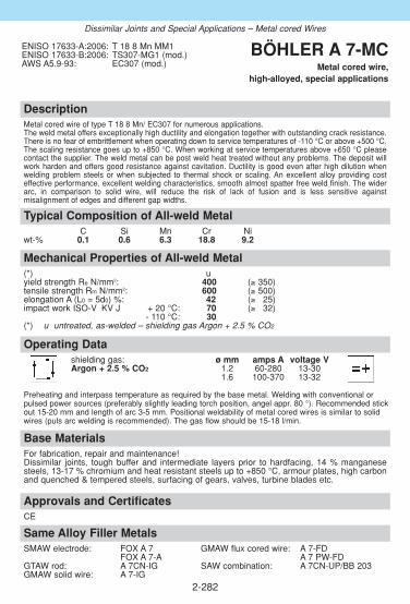
2-282
Dissimilar Joints and Special Applications – Metal cored Wires
DescriptionMetal cored wire of type T 18 8 Mn/ EC307 for numerous applications.The weld metal offers exceptionally high ductility and elongation together with outstanding crack resistance.There is no fear of embrittlement when operating down to service temperatures of -110 °C or above +500 °C.The scaling resistance goes up to +850 °C. When working at service temperatures above +650 °C pleasecontact the supplier. The weld metal can be post weld heat treated without any problems. The deposit willwork harden and offers good resistance against cavitation. Ductility is good even after high dilution whenwelding problem steels or when subjected to thermal shock or scaling. An excellent alloy providing costeffective performance, excellent welding characteristics, smooth almost spatter free weld finish. The widerarc, in comparison to solid wire, will reduce the risk of lack of fusion and is less sensitive against misalignment of edges and different gap widths.
Approvals and CertificatesCE
Base MaterialsFor fabrication, repair and maintenance!Dissimilar joints, tough buffer and intermediate layers prior to hardfacing, 14 % manganesesteels, 13-17 % chromium and heat resistant steels up to +850 °C, armour plates, high carbonand quenched & tempered steels, surfacing of gears, valves, turbine blades etc.
Typical Composition of All-weld MetalC Si Mn Cr Ni
wt-% 0.1 0.6 6.3 18.8 9.2
ENISO 17633-A:2006: T 18 8 Mn MM1ENISO 17633-B:2006: TS307-MG1 (mod.)AWS A5.9-93: EC307 (mod.)
BÖHLER A 7-MCMetal cored wire,
high-alloyed, special applications
Mechanical Properties of All-weld Metal(*) uyield strength Re N/mm2: 400 (≥ 350)tensile strength Rm N/mm2: 600 (≥ 500)elongation A (L0 = 5d0) %: 42 (≥ 325)impact work ISO-V KV J + 20 °C: 70 (≥ 332)
- 110 °C: 30(*) u untreated, as-welded – shielding gas Argon + 2.5 % CO2
Operating Datashielding gas: ø mm amps A voltage VArgon + 2.5 % CO2 1.2 60-280 13-30
1.6 100-370 13-32
Preheating and interpass temperature as required by the base metal. Welding with conventional orpulsed power sources (preferably slightly leading torch position, angel appr. 80 °). Recommended stickout 15-20 mm and length of arc 3-5 mm. Positional weldability of metal cored wires is similar to solidwires (puls arc welding is recommended). The gas flow should be 15-18 l/min.
Same Alloy Filler Metals SMAW electrode: FOX A 7 GMAW flux cored wire: A 7-FD
FOX A 7-A A 7 PW-FDGTAW rod: A 7CN-IG SAW combination: A 7CN-UP/BB 203GMAW solid wire: A 7-IG

2-283
Dissimilar Joints and Special Applications – Metal cored Wires
DescriptionMetal cored wire of type T 23 12 L / ER309L for welding dissimilar joints between high alloyed Cr- andCrNi(Mo)-steels and mild- or low alloyed steels.BÖHLER CN 23/12-MC is designed for very good welding, wetting and feeding characteristics as well asgood safety after dilution when welding dissimilar joints. Suitable for service temperatures between -120 °C and +300 °C.The wider arc, in comparison to solid wire, will reduce the risk of lack of fusion and is less sensitive againstmisalignment of edges and different gap widths.
Approvals and Certificates–
Base Materialsdissimilar joint welds:of and between high-strength, mild steels and low-alloyed QT-steels, stainless, ferritic Cr- andaustenitic Cr-Ni- steels, manganese steelssurfacing:for the first layer of corrosion resistant weld surfacing on ferritic-perlitic steels in boiler and pres-sure vessel parts up to fine-grained steel S500N, as well as of high temperature steels like22NiMoCr4-7 acc. SEW-Werkstoffblatt 365, 366, 20MnMoNi5-5 and G18NiMoCr3-7
Typical Composition of All-weld MetalC Si Mn Cr Ni
wt-% ≤ 0.03 0.6 1.4 23.0 12.5
ENISO 17633-A:2006: T 23 12 L MM1ENISO 17633-B:2006: TS309L-MG1AWS A5.9-93: EC309L
BÖHLER CN 23/12-MCMetal cored wire,
high-alloyed, special applications
Mechanical Properties of All-weld Metal(*) uyield strength Re N/mm2: 400 (≥ 350)tensile strength Rm N/mm2: 540 (≥ 520)elongation A (L0 = 5d0) %: 32 (≥ 330)impact work ISO-V KV J + 20 °C: 90 (≥ 347)
- 120 °C: 70 (≥ 332)(*) u untreated, as-welded – shielding gas Argon + 2.5 % CO2
Operating Datashielding gas: ø mm amps A voltage VArgon + 2.5 % CO2 1.2 60 - 280 13 - 30
1.6 100 - 370 13 - 32
Preheat and interpass temperature as required by the base metal. Welding with conventional or pulsed power sources (preferably slightly leading torch position, angel appr. 80 °). Recommended stick out 15-20 mm and length of arc 3-5 mm. Positional weldability of metal cored wires is similar to solid wires (puls arc welding is recommended). The gas flow should be 15-18 l/min.
Same Alloy/Similar Alloy Filler Metals SMAW electrode: FOX CN 23/12-A GMAW flux cored wire: CN 23/12-FD
FOX CN 23/12 Mo-A CN 23/12 PW-FDGTAW rod: CN 23/12-IG CN 23/12 Mo-FDGMAW solid wire: CN 23/12-IG CN 23/12 Mo PW-FD
SAW combination: CN 23/12-UP/BB 202

2-284
Dissimilar Joints and Special Applications – GMAW Flux-cored Wires
DescriptionRutile flux cored welding wire preferable for flat & horizontal welding positions. BÖHLER A7-FD achieveshigh productivity and is easy to operate providing excellent welding characteristics, self releasing slag,almost no spatter formation and temper discoloration, smooth weld finish and safe penetration. Increasedtravel speeds as well as little demand for cleaning provide considerable savings in time and money.The weld deposit offers high ductility and elongation together with excellent crack resistance even when sub-jected to thermal shock. It will work harden and offers good resistance against cavitation. Ductility is goodeven after high dilution when welding problem steels. There is no fear of embrittlement when operating downto service temperatures of -100 °C or above +500 °C. The scaling resistance goes up to +850 °C. Whenworking at service temperatures above +650 °C please contact the supplier.
Approvals and Certificates–
Base MaterialsFor fabrication, repair and maintenance!Dissimilar joints, tough buffer and intermediate layers prior to hardfacing, 14 % manganesesteels, 13 - 17 % chromium heat resistant steels up to +850 °C, armour plates, high carbon andquenched & tempered steels, surfacing of gears, valves, turbine blades etc.
Typical Composition of All-weld MetalC Si Mn Cr Ni
wt-% 0.1 0.7 6.5 18.5 8.8
ENISO 17633-A:2006: T 18 8 Mn R M 3T 18 8 Mn R C 3
ENISO 17633-B:2006: TS307-FB0 (mod.)AWS A5.22-95: E307T0-G
BÖHLER A 7-FDGMAW flux cored wire,
high-alloyed, special applications
Mechanical Properties of All-weld Metal(*) uyield strength Re N/mm2: 420 (≥ 400)tensile strength Rm N/mm2: 630 (≥ 600)elongation A (L0 = 5d0) %: 39 (≥ 335)impact work ISO-V KV J + 20 °C: 60
- 100 °C: (≥ 332)(*) u untreated, as-welded – shielding gas Argon + 18 % CO2
Operating Datare-drying if necessary: 150 °C/24 h ø mm amps A voltage Vshielding gases: 1.2 125 - 280 20 - 34Argon + 15 - 25 % CO2 1.6 200 - 350 25 - 35 100 % CO2
Welding with standard GMAW-facilities possible, slightly trailingtorch position (angel appr. 80 °), when using 100 % CO2 as shielding gas it isnecessary to increase the voltage by 2 V. The gas flow should be 15-18 l/min.Preheating and interpass temperature as required by the base metal.
Same Alloy Filler Metals SMAW electrode: FOX A 7-A Metal cored wire: A 7-MC
FOX A 7 GMAW flux cored wire: A 7 PW-FDGTAW rod: A 7CN-IG SAW combination: A 7CN-UP/BB 203GMAW solid wire: A 7-IG
hardness appro. 200 HBstress hardenedup to 400 HV
Ø 1
.2Ø
1.6

2-285
Dissimilar Joints and Special Applications – GMAW Flux-cored Wires
DescriptionRutile flux cored welding wire with fast freezing slag providing positional welding characteristics and fast tra-vel speedsl BÖHLER A7 PW-FD achieves high productivity and is easy to operate providing excellent wel-ding characteristics, self releasing slag, almost no spatter formation and temper discoloration, smooth weldfinish and safe penetration. The weld deposit offers high ductility and elongation together with excellent crackresistance even when subjected to thermal shock. It will work harden and offers good resistance against cavi-tation. Ductility is good even after high dilution when welding problem steels. Beside the major savings in timeand cost BÖHLER offers a high production quality level together with lowest probabilities for welding errors.Increased travel speeds as well as little demand for cleaning and pickling provide considerable savings intime and money. Description of all-weld-metal: strain hardening, good resistance against cavitation, crackresistance, resistance against thermal shock, scaling resistance goes up to +850 °C. There is no fear ofembrittlement when operating down to service temperatures of -100 °C or above +500 °C. When working atservice temperatures above +650 °C please contact the supplier.
Approvals and Certificates–
Base MaterialsFor fabrication, repair and maintenance!Dissimilar joints, tough buffer and intermediate layers prior to hardfacing, 14 % manganesesteels, 13 - 17 % chromium heat resistant steels up to +850 °C, armour plates, high carbon andquenched & tempered steels, surfacing of gears, valves, turbine blades etc.
Typical Composition of All-weld MetalC Si Mn Cr Ni
wt-% 0.1 0.8 6.8 18.8 9.0
ENISO 17633-A:2006: T 18 8 Mn P M 2T 18 8 Mn P C 2
ENISO 17633-B:2006: TS307-FB1AWS A5.22-95: E307T1-G
BÖHLER A 7 PW-FDGMAW flux cored wire,
high-alloyed, special applications
Mechanical Properties of All-weld Metal(*) uyield strength Re N/mm2: 420 (≥ 400)tensile strength Rm N/mm2: 630 (≥ 600)elongation A (L0 = 5d0) %: 39 (≥ 335)impact work ISO-V KV J + 20 °C: 65
- 100 °C: (≥ 332)(*) u untreated, as-welded – shielding gas Argon + 18 % CO2
Operating Datare-drying if necessary: 150 °C/24 h ø mm amps A voltage Vshielding gases: 1.2 120 - 190 21 - 29Argon + 15 - 25 % CO2
100 % CO2Welding with standard GMAW-facilities possible, slightly trailing torch position (angel approx. 80 °C), slight weaving is recommended for all welding positions, when using 100 % CO2 as shielding gas it is necessary to increase the voltage by 2 V. The gas flow should be 15-18 l/min.Preheating and interpass temperature as required by the base metal.
Same Alloy Filler Metals SMAW electrode: FOX A 7-A Metal cored wire: A 7-MC
FOX A 7 GMAW flux cored wire: A 7-FDGTAW rod: A 7CN-IG SAW combination: A 7CN-UP/BB 203GMAW solid wire: A 7-IG
hardness appro. 200 HBstress hardenedup to 400 HV

DescriptionRutile flux-cored welding wire for GMAW of dissimilar joints of Cr- and CrNi(Mo)-steels and non- or low-alloysteels, as well as weld cladding of un- or low alloyed base metals preferably in flat or horizontal position. Thisproduct achieves high productivity and is easy to operate achieving excellent welding characteristics, self relea-sing slag, almost no spatter formation and temper discolouration, smooth weld finish and safe penetration.Beside the major savings in time and cost BÖHLER offers a high production quality level together with lowestprobabilities for welding errors. Increased travel speeds as well as little demand for cleaning and pickling provi-de considerable savings in time and money. Suitable for service temperatures of -60 °C to +300 °C.BÖHLER CN 23/12-FD ø 0.9 mm is well suitable for welding of sheet metal (thickness greater than 1.5 mm, forout-of-position welding greater than 5 mm). The slag concept gives the opportunity to weld this diameter in allwelding positions. Wires with ø 1.2 mm can be used for wall thicknesses from 3 mm and up.Wire ø 0.9 mm is designed for positional welding, wire ø 1.2 mm and 1.6 mm are recommended mainly for down-hand and horizontal welding positions.
Approvals and CertificatesTÜV-D (5350.), DB (43.014.16), ÖBB, TÜV-A (516), CWB (E309LT0-1(4)), GL (4571 (C1, M21)),SEPROZ, LR (DX, CMn/SS), CE
Base Materialsdissimilar joint welds: of and between high-strength, mild steels and low-alloyed QT-steels, stainless, ferritic Cr-and austenitic Cr-Ni- steels, manganese steelssurfacing: for the first layer of corrosion resistant weld surfacing on ferritic-perlitic steels in boiler and pressurevessel parts up to fine-grained steel S500N, as well as of high temperature steels like 22NiMoCr4-7 acc. SEW-Werkstoffblatt 365, 366, 20MnMoNi5-5 and G18NiMoCr3-7
Typical Composition of All-weld MetalC Si Mn Cr Ni
wt-% 0.03 0.7 1.4 23.0 12.5
ENISO 17633-A:2006: T 23 12 L R M (C) 3ENISO 17633-B:2006: TS309L-FB0AWS A5.22-95: E309LT0-4 (1)ENISO 17633-A:2006: T 23 12 L P M (C) 1 (for ø 0.9 mm)ENISO 17633-B:2006: TS309L-FB1AWS A5.22-95: E309LT1-4/-1 (for ø 0.9 mm)
BÖHLER CN 23/12-FDGMAW flux cored wire, high-alloyed,
special applications
2-286
Same Alloy/Similar Alloy Filler Metals SMAW electrode: FOX CN 23/12-A Metal cored wire: CN 23/12-MC
FOX CN 23/12 Mo-A GMAW flux cored wire: CN 23/12 PW-FDGTAW rod: CN 23/12-IG CN 23/12 Mo-FD GMAW solid wire: CN 23/12-IG CN 23/12 Mo PW-FD
SAW combination: CN 23/12-UP/BB 202
Mechanical Properties of All-weld Metal(*) u untreated, as-welded – shielding gas Ar+18%CO2yield strength Re N/mm2: 400 (≥ 350)tensile strength Rm N/mm2: 540 (≥ 520)elongation A (L0 = 5d0) %: 35 (≥ 330)impact work ISO-V KV J + 20 °C: 60 (≥ 347) - 60 °C: 45 (≥ 332)
Dissimilar Joints and Special Applications – GMAW Flux-cored Wires
Operating Datare-drying if necessary: ø mm amps A voltage V150 °C/24 h 0.9 100 - 160 21 - 30shielding gases: 1.2 125 - 280 20 - 34Argon + 15 - 25 % CO2 1.6 200 - 350 25 - 35 100 % CO2
Welding with standard GMAW-facilities possible, slightly trailing torch position (angel appr. 80 °), when using 100 % CO2 as shielding gas it is necessary to increase the voltage by 2 V. The gas flow should be 15-18 l/min.Preheat and interpass temperatures as required by the base metal.
Ø 0
.9Ø
1.2
Ø 1
.6

DescriptionBÖHLER CN 23/12 PW-FD is a rutile flux cored welding wire with fast freezing slag providing excellent positional welding characteristics and fast travel speeds. It is easy to use and operates with a powerful penetrating spray arc transfer, minimum spatter formation and self releasing slag.This flux cored welding wire offers many economical and quality advantages over solid wire pulse arc welding. High deposition rates and productivity gains are easily achievable. Additional cost effective bene-fits are offered through use of less expensive shielding gases, good wetting characteristics (less grinding),little temper discoloration & bead oxidation, easy operation and safe penetration (reduces the risk of welddefects and associated repair work costs), and smooth and clean weld finish (less post weld work).Due to its characteristics mainly for positional welding and service temperatures between -60 °C to+300 °C. For downhand & horizontal welding positions (1G,1F, 2F) our flux cored wire BÖHLER CN 23/12-FDshould be preferred.
Approvals and CertificatesTÜV-D (09115.), DB (43.014.22), ABS (E309 LT 1-1(4)), LR (DXV u. O, CMn/SS), GL (4332S{C1, M21}), CWB (E309LT0-1(4)), SEPROZ, ÖBB, CE
Same Alloy/Similar Alloy Filler MetalsSMAW electrode: FOX CN 23/12-A Metal cored wire: CN 23/12-MC
FOX CN 23/12 Mo-A GMAW flux cored wire: CN 23/12-FDGTAW rod: CN 23/12-IG CN 23/12 Mo-FDGMAW solid wire: CN 23/12-IG CN 23/12 Mo PW-FD
SAW combination: CN 23/12-UP/BB 202
Base Materialsdissimilar joint welds: of and between high-strength, mild steels and low-alloyed QT-steels, stainless,ferritic Cr- and austenitic Cr-Ni- steels, manganese steelssurfacing: for the first layer of corrosion resistant weld surfacing on ferritic-perlitic steels in boiler andpressure vessel parts up to fine-grained steel S500N, as well as of high temperature steels like22NiMoCr4-7 acc. SEW-Werkstoffblatt 365, 366, 20MnMoNi5-5 and G18NiMoCr3-7
Operating Datare-drying if necessary: ø mm amps A voltage Vpossible, 150 °C / 24 h 1.2 100 - 220 20 - 31shielding gases: Argon + 15 - 25 % CO2 1.6 175 - 260 21 - 29
100 % CO2
Welding with standard GMAW-facilities possible, slightly trailing torch position (angel appr. 80 °), slight weaving is recommended for all welding positions; when using 100 % CO2 as shielding gas it is necessary toincrease the voltage by 2 V. The gas flow should be 15-18 l/min. Preheat and interpass temperatures asrequired by the base metal.
Mechanical Properties of All-weld Metal(*) u yield strength Re N/mm2: 400 (≥ 350)tensile strength Rm N/mm2: 540 (≥ 520)elongation A (L0 = 5d0) %: 35 (≥ 330)impact work ISO-V KV J + 20 °C: 65 (≥ 347)
- 60 °C: 50 (≥ 332)(*) u untreated, as-welded – shielding gas Ar + 18 % CO2
Typical Composition of All-weld MetalC Si Mn Cr Ni
wt-% 0.03 0.7 1.4 23.0 12.5
ENISO 17633-A:2006: T 23 12 L P M 1T 23 12 L P C 1
ENISO 17633-B:2006: TS309L-FB1AWS A5.22-95: E309LT1-4
E309LT1-1
BÖHLER CN 23/12 PW-FD
GMAW flux cored wire, high-alloyed,special applications
2-287
Dissimilar Joints and Special Applications – GMAW Flux-cored Wires
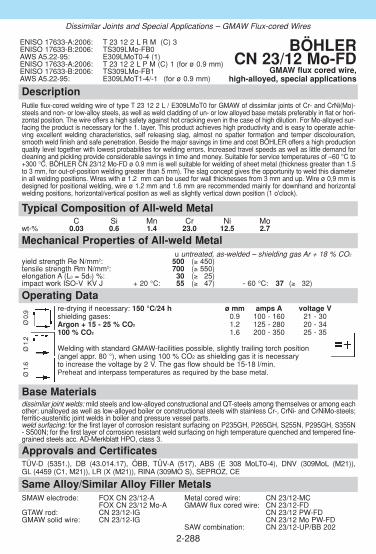
DescriptionRutile flux-cored welding wire of type T 23 12 2 L / E309LMoT0 for GMAW of dissimilar joints of Cr- and CrNi(Mo)-steels and non- or low-alloy steels, as well as weld cladding of un- or low alloyed base metals preferably in flat or hori-zontal position. The wire offers a high safety against hot cracking even in the case of high dilution. For Mo-alloyed sur-facing the product is necessary for the 1. layer. This product achieves high productivity and is easy to operate achie-ving excellent welding characteristics, self releasing slag, almost no spatter formation and temper discolouration,smooth weld finish and safe penetration. Beside the major savings in time and cost BÖHLER offers a high productionquality level together with lowest probabilities for welding errors. Increased travel speeds as well as little demand forcleaning and pickling provide considerable savings in time and money. Suitable for service temperatures of –60 °C to+300 °C. BÖHLER CN 23/12 Mo-FD ø 0.9 mm is well suitable for welding of sheet metal (thickness greater than 1.5to 3 mm, for out-of-position welding greater than 5 mm). The slag concept gives the opportunity to weld this diameterin all welding positions. Wires with ø 1.2 mm can be used for wall thicknesses from 3 mm and up. Wire ø 0,9 mm isdesigned for positional welding, wire ø 1.2 mm and 1.6 mm are recommended mainly for downhand and horizontalwelding positions, horizontal/vertical position as well as slightly vertical down position (1 o'clock).
Approvals and CertificatesTÜV-D (5351.), DB (43.014.17), ÖBB, TÜV-A (517), ABS (E 308 MoLT0-4), DNV (309MoL (M21)), GL (4459 (C1, M21)), LR (X (M21)), RINA (309MO S), SEPROZ, CE
Base Materialsdissimilar joint welds: mild steels and low-alloyed constructional and QT-steels among themselves or among eachother; unalloyed as well as low-alloyed boiler or constructional steels with stainless Cr-, CrNi- and CrNiMo-steels;ferritic-austenitic joint welds in boiler and pressure vessel parts.weld surfacing: for the first layer of corrosion resistant surfacing on P235GH, P265GH, S255N, P295GH, S355N- S500N; for the first layer of corrosion resistant weld surfacing on high temperature quenched and tempered fine-grained steels acc. AD-Merkblatt HPO, class 3.
Typical Composition of All-weld MetalC Si Mn Cr Ni Mo
wt-% 0.03 0.6 1.4 23.0 12.5 2.7
ENISO 17633-A:2006: T 23 12 2 L R M (C) 3ENISO 17633-B:2006: TS309LMo-FB0AWS A5.22-95: E309LMoT0-4 (1)ENISO 17633-A:2006: T 23 12 2 L P M (C) 1 (for ø 0.9 mm)ENISO 17633-B:2006: TS309LMo-FB1AWS A5.22-95: E309LMoT1-4/-1 (for ø 0.9 mm)
BÖHLER CN 23/12 Mo-FD
GMAW flux cored wire, high-alloyed, special applications
2-288
Mechanical Properties of All-weld Metal(*) u untreated, as-welded – shielding gas Ar + 18 % CO2
yield strength Re N/mm2: 500 (≥ 450)tensile strength Rm N/mm2: 700 (≥ 550)elongation A (L0 = 5d0) %: 30 (≥ 325)impact work ISO-V KV J + 20 °C: 55 (≥ 347) - 60 °C: 37 (≥ 332)
Same Alloy/Similar Alloy Filler Metals SMAW electrode: FOX CN 23/12-A Metal cored wire: CN 23/12-MC
FOX CN 23/12 Mo-A GMAW flux cored wire: CN 23/12-FD GTAW rod: CN 23/12-IG CN 23/12 PW-FDGMAW solid wire: CN 23/12-IG CN 23/12 Mo PW-FD
SAW combination: CN 23/12-UP/BB 202
Dissimilar Joints and Special Applications – GMAW Flux-cored Wires
Operating Datare-drying if necessary: 150 °C/24 h ø mm amps A voltage Vshielding gases: 0.9 100 - 160 21 - 30Argon + 15 - 25 % CO2 1.2 125 - 280 20 - 34100 % CO2 1.6 200 - 350 25 - 35
Welding with standard GMAW-facilities possible, slightly trailing torch position (angel appr. 80 °), when using 100 % CO2 as shielding gas it is necessary to increase the voltage by 2 V. The gas flow should be 15-18 l/min. Preheat and interpass temperatures as required by the base metal.
Ø 0
.9Ø
1.2
Ø 1
.6

DescriptionBÖHLER CN 23/12 Mo PW-FD is a rutile flux cored welding wire with fast freezing slag providing excel-lent positional welding characteristics and fast travel speeds. It is easy to use and operates with a power-ful penetrating spray arc transfer, minimum spatter formation and self releasing slag.This flux cored welding wire offers many economical and quality advantages over solid wire pulse arcwelding. High deposition rates and productivity gains are easily achievable. Additional cost effectivebenefits are offered through use of less expensive shielding gases (Argon + 15-25 % CO2 or 100 % CO2),good wetting characteristics (less grinding), little temper discoloration & bead oxidation, easy operationand safe penetration (reduces the risk of weld defects and associated repair work costs), and smooth andclean weld finish (less post weld work).Due to its characteristics mainly for positional welding and service temperatures between -60 °C to +300 °C. For downhand & horizontal welding positions (1G, 1F, 2F) our flux cored wire BÖHLERCN 23/12 Mo-FD should be preferred.
Approvals and CertificatesTÜV-D (09116.), BV (309Mo), LR (SS/CMn), SEPROZ, CE
Same Alloy/Similar Alloy Filler MetalsSMAW electrode: FOX CN 23/12-A Metal cored wire: CN 23/12-MC
FOX CN 23/12 Mo-A GMAW flux cored wire: CN 23/12 Mo-FD GTAW rod: CN 23/12-IG CN 23/12-FDGMAW solid wire: CN 23/12-IG CN 23/12 PW-FD
SAW combination: CN 23/12-UP/BB 202
Base Materialsdissimilar joint welds: mild steels and low-alloyed constructional and QT-steels among themselves oramong each other; unalloyed as well as low-alloyed boiler or constructional steels with stainless Cr-, CrNi- and CrNiMo-steels; ferritic-austenitic joint welds in boiler and pressure vessel parts.weld surfacing: for the first layer of corrosion resistant surfacing on P235GH, P265GH, S255N,P295GH, S355N - S500N; for the first layer of corrosion resistant weld surfacing on high temperaturequenched and tempered fine-grained steels acc. AD-Merkblatt HPO, class 3.
Operating Datare-drying if necessary: ø mm amps A voltage Vpossible, 150 °C / 24 h 1.2 100 - 220 20 - 31shielding gases: Argon + 15 - 25 % CO2
100 % CO2
Welding with standard GMAW-facilities possible, slightly trailing torch position (angel appr. 80 °), slight weavingis recommended for positional welding. When using 100 % CO2 as shielding gas it is necessary to increase thevoltage by 2 V. The gas flow should be 15-18 l/min. Preheat and interpass temperatures as required bythe base metal.
Mechanical Properties of All-weld Metal(*) u yield strength Re N/mm2: 530 (≥ 450)tensile strength Rm N/mm2: 720 (≥ 550)elongation A (L0 = 5d0) %: 32 (≥ 325)impact work ISO-V KV J + 20 °C: 65 (≥ 347)
- 60 °C: 50 (≥ 332)(*) u untreated, as-welded – shielding gas Ar + 18 % CO2
Typical Composition of All-weld MetalC Si Mn Cr Ni Mo
wt- % 0.03 0.7 1.4 23.0 12.5 2.7
ENISO 17633-A:2006: T 23 12 2 L P M (C) 1ENISO 17633-B:2006: TS309LMo-FB1AWS A5.22-95: E309LMoT1-4
E309LMoT1-1
BÖHLER CN 23/12 Mo PW-FD
GMAW flux cored wire, high-alloyed,special applications
2-289
Dissimilar Joints and Special Applications – GMAW Flux-cored Wires

DescriptionSAW wire/flux combination of type S 18 8 Mn / (ER307) for numerous applications. BÖHLER A 7-UP // BB 203 yields a weld deposit offering exceptionally high ductility and elon-gation together with outstanding crack resistance. There is no fear of embrittlement when ope-rating down to service temperatures of -100 °C or above +500 °C. The scaling resistance goesup to +850 °C. When working at service temperatures above +650 °C please contact the sup-plier. The weld metal can be post weld heat treated without any problems. The deposit will workharden and offers good resistance against cavitation. Ductility is good even after high dilutionwhen welding problem steels or when subjected to thermal shock or scaling. An excellent alloyproviding cost effective performance. BÖHLER BB 203 is a fluoride-basic, agglomerated fluxproviding good operating characteristics, smooth beads and a low hydrogen weld metal. Forinformation regarding this sub-arc welding flux see our detailed data sheet.
Approvals and CertificatesSAW solid wire: TÜV-D (02604.), CE
Base MaterialsFor fabrication, repair and maintenance!Dissimilar joints, tough buffer and intermediate layers prior to hardfacing, 14 % manganesesteels, 13 - 17 % chromium heat resistant steels, armour plates, high carbon and quenched &tempered steels, surfacing of gears, valves, turbine blades etc.
Operating Datare-drying of sub-arc flux: ø mm300-350 °C, 2 h - 10 h 3.0Preheat and interpass temperatures as required by the base metal.
SAW solid wire:EN 12072:1999: S 18 8 MnAWS A5.9-93: ER307 (mod.)
sub-arc flux:EN 760:1996: SA FB 2 DC
BÖHLER A 7 CN-UP // BB 203
SAW wire/flux-combination,high-alloyed, special applications
2-290
Mechanical Properties of All-weld Metal(*) uyield strength Re N/mm2: ≥ 390tensile strength Rm N/mm2: ≥ 620elongation A (L0 = 5d0) %: ≥ 336impact work ISO-V KV J + 20 °C: ≥ 395
- 50 °C: ≥ 360- 100 °C: ≥ 340
(*) u untreated, as-welded
Typical Composition of Solid Wire and All-weld MetalC Si Mn Cr Ni
SAW wire wt-% 0.08 0.9 7.0 19.2 9.0 SAW wire wt-% 0.06 0.8 6.0 18.7 9.0
Same Alloy Filler Metals SMAW electrode: FOX A 7 GMAW solid wire: A 7-IG
FOX A 7-A Metal cored wire: A 7-MCGTAW rod: A 7CN-IG GMAW flux cored wire: A 7-FD, A 7 PW-FD
Dissimilar Joints and Special Applications – SAW Wire/Flux-Combinations

DescriptionSAW wire/flux combination of type S 23 12 L / ER309L. This is a standard alloy for welding dissimilar joints, steels with poor weldability and weld surfacing. SAW wire/flux-combination for multi-pass welding, smooth beads, low hydrogen contents(HD > 5 ml/100 g), easy slag removal without any slag residues and good welding characteristicseven for fillet welds are very much appreciated by users. The average ferrite content is 16 FN.Suitable up to service temperatures of +300 °C.BÖHLER BB 202 is a fluoride-basic, agglomerated flux providing good operating characteristics.For information regarding this sub-arc welding flux see our detailed data sheet.
Approvals and CertificatesDNV (309L)SAW solid wire: TÜV-D (2604.), CE
Base Materialsdissimilar joint welds:of and between high-strength, mild steels and low-alloyed QT-steels, stainless, ferritic Cr- andaustenitic Cr-Ni- steels, manganese steelssurfacing:for the first layer of corrosion resistant weld surfacing on ferritic-perlitic steels in boiler and pres-sure vessel parts up to fine-grained steel S500N, as well as of high temperature steels like22NiMoCr4-7 acc. SEW-Werkstoffblatt 365, 366, 20MnMoNi5-5 and G18NiMoCr3-7
SAW solid wire:EN 12072:1999: S 23 12 LAWS A5.9.93: ER309L
sub-arc flux:EN 760:1996: SA FB 2 DC
BÖHLER CN 23/12-UP // BB 202
SAW wire/flux-combination,high-alloyed, special applications
2-291
Operating Datare-drying of sub-arc flux: ø mm300-350 °C / 2 h - 10 h 3.0max. amperage: 800 APreheat and interpass temperatures as required by the base metal.
Typical Composition of Solid Wire and All-weld MetalC Si Mn Cr Ni
SAW wire wt-% ≤ 0.02 0.5 1.8 24.0 13.2 all-weld metal % ≤ 0.015 0.6 1.3 23.5 13.2
Same Alloy/Similar Alloy Filler Metals SMAW electrode: FOX CN 23/12-A Metal cored wire: CN 23/12-MC
FOX CN 23/12 Mo-A GMAW flux cored wire: CN 23/12-FD GTAW rod: CN 23/12-IG CN 23/12 PW-FDGMAW solid wire: CN 23/12-IG CN 23/12 Mo-FD
CN 23/12 Mo PW-FD
Dissimilar Joints and Special Applications – SAW Wire/Flux-Combinations
Mechanical Properties of All-weld Metal(*) uyield strength Re N/mm2: ≥ 350tensile strength Rm N/mm2: ≥ 600elongation A (L0 = 5d0) %: ≥ 335impact work ISO-V KV J + 20 °C: ≥ 100(*) u untreated, as-welded

2-292
Notes

2-293
Notes

2-294
Notes
2-295
2.8 Filler metals for Heat Resistant Steels
ObjectivesThis section contains data sheets for filler metals that are suitable for wel-ding heat-resistant steels. Heat-resistant steels are used at temperatures over 550 °C. In addition toscale-resistance and adequate high-temperature strength there is also arequirement for the lowest possible changes in volume during repeated hea-ting up and cooling down so that the oxide layers do not crack open. Overand above this they should also have adequate resistance to various annea-ling and furnace atmospheres. The Cr, Si and Al alloying elements give rise to the scale resistance due tothe formation of dense and adhesive oxide layers. The Cr-Al alloy steels areferritic and less suitable for welding but are extremely resistant in sulphur-containing gases. The Cr-Ni-Si alloy steels exhibit an austenitic microstruc-ture, have excellent resistance in carburising furnace atmospheres contai-ning nitrogen but form a low melting point eutectic with nickel in sulphurousgases at approx. 700 °C.With these steels it is important to be aware of the embrittlement ranges400...500 °C (with Cr contents above 15 %) and above 950 °C (grain growth)in ferritic steels and the sphase embrittlement between 650 and 800 °C with Cr contents above 20 %.
Content
OVERVIEW . . . . . . . . . . . . . . . . . . . . . . . . . . . . . . . . . . . . . . . . . . . . . . .296
SMAW COVERED ELECTRODES . . . . . . . . . . . . . . . . . . . . . . . . . . . . .297
GTAW RODS . . . . . . . . . . . . . . . . . . . . . . . . . . . . . . . . . . . . . . . . . . . . . .305
GMAW SOLID WIRES . . . . . . . . . . . . . . . . . . . . . . . . . . . . . . . . . . . . . . .311
◆
◆
Product Information

2-296
Overview – Standard Classifications
Böhler EN / ENISO AWSSMAW covered electrodesFOX FA 1600: E 25 4 B 2 2 –FOX FF 1600: E 22 12 B 2 2 A5.4-92: E309-15(mod.)FOX FF-A 1600: E 22 12 R 3 2 A5.4-92: E309-17(mod.)FOX FFB 1600: E 25 20 B 2 2 A5.4-92: E310-15(mod.)FOX FFB-A 1600: E 25 20 R 3 2 A5.4-92: E310-16 FOX CN 21/33 Mn 1600: E Z 21 33 B 4 2 –FOX CN 25/35 Nb 1600: E Z 25 35 Nb B 6 2 –FOX CN 35/45 Nb 1600: E Z 35 45 Nb B 6 2 –
GTAW rodsFA-IG 12072: W 25 4 –FF-IG 12072: W 22 12 A5.9-93: ER309(mod.)FFB-IG 12072: W 25 20 Mn A5.9-93: ER310(mod.)CN 21/33 Mn-IG 12072: W Z21 33 Nb –CN 25/35 Nb-IG 12072: W Z25 35 Nb –CN 35/45 Nb-IG 12072: W Z35 45 Nb –
GMAW solid wiresFA-IG 12072: G 25 4 –FF-IG 12072: G 22 12 H A5.9-93: ER309(mod.)FFB-IG 12072: G 25 20 Mn A5.9-93: ER310(mod.)CN 21/33 Mn-IG 12072: G Z21 33 Nb –CN 25/35 Nb-IG 12072: G Z25 35 Nb –CN 35/45 Nb-IG 12072: G Z35 45 Nb –
◆
Overview – Typical Chemical Composition
Böhler C Si Mn Cr Ni Nb Fe TiSMAW covered electrodesFOX FA 0.1 0.5 1.2 25.0 5.4FOX FF 0.1 1.0 1.1 22.0 12.0FOX FF-A 0.1 0.8 0.9 22.5 12.5FOX FFB 0.12 0.6 3.2 25.0 20.5FOX FFB-A 0.12 0.5 2.2 26.0 21.0FOX CN 21/33 Mn 0.14 0.3 4.5 21.0 33.0 1.3FOX CN 25/35 Nb 0.4 1.0 1.5 25.0 35.0 1.2FOX CN 35/45 Nb 0.45 1.0 0.8 35.0 45.5 0.9
GTAW rodsFA-IG 0.07 0.8 1.2 25.7 4.5FF-IG 0.1 1.1 1.6 22.5 11.5FFB-IG 0.13 0.9 3.2 24.6 20.5CN 21/33 Mn-IG 0.12 0.2 4.8 21.8 32.5 1.2CN 25/35 Nb-IG 0.42 1.2 1.8 26.0 35.0 1.3CN 35/45 Nb-IG 0.42 1.5 1.0 35.0 45.5 0.8
GMAW solid wiresFA-IG 0.07 0.8 1.2 25.7 4.5FF-IG 0.1 1.1 1.6 22.5 12.5FFB-IG 0.13 0.9 3.2 24.6 20.5CN 21/33 Mn-IG 0.12 0.2 4.8 21.8 32.5 1.2CN 25/35 Nb-IG 0.42 1.2 1.8 26.0 35.0 1.3CN 35/45 Nb-IG 0.42 1.5 1.0 35.0 45.5 0.8
◆
Heat Resistant Filler Metals

DescriptionBasic electrode, core wire alloyed for welding heat resistant steels. For furnaces requiring elevated resistance to reducing and oxidizing sulphurous gases as well as for final passes ofweld joints in heat resistant, ferritic CrSiAl steels. Scaling resistant up to +1100 °C.
Approvals and CertificatesSEPROZ
Base Materialsferritic-austenitic1.4821 X 20 CrNiSi 25 4, 1.4823 G-X 40 CrNiSi 27 4ferritic-perlitic1.4713 X 10 CrAl 7, 1.4724 X 10 CrAl 13, 1.4742 X 10 CrAl 18, 1.4762 X 10 CrAl 25,1.4710 X 30 CrSi 6, 1.4740 G-X 40 CrSi 17
AISI 327, ASTM A297HC
Typical Composition of All-weld MetalC Si Mn Cr Ni
wt-% 0.10 0.5 1.2 25.0 5.4
EN 1600:1997: E 25 4 B 2 2 BÖHLER FOX FASMAW basic electrode, high-alloyed,
heat resistant
2-297
Same Alloy Filler Metals GTAW rod: FA-IG GMAW solid wire: FA-IG
Mechanical Properties of All-weld Metal(*) uyield strength Re N/mm2: 520 (≥ 490)tensile strength Rm N/mm2: 680 (≥ 640)elongation A (L0 = 5d0) %: 22 (≥ 315)impact work ISO-V KV J + 20 °C: 45 (≥ 330)(*) u untreated, as-welded
Operating Datare-drying if necessary: ø mm L mm amps A– 2.5 300 50 - 175electrode identification: 3.2 350 80 - 105FOX FA E 25 4 B 4.0 350 100 - 130
Preheating and interpass temperatures 200 - 400 °C, depending on the relevant base metaland material thickness.
Heat Resistant Filler Metals - SMAW Covered Electrodes

DescriptionBasic electrode, core wire alloyed for welding analogous, heat resistant rolled, forged and caststeels as well as heat resistant ferritic CrSiAl steels. For weld joints exposed to reducing, sulphurous gases, the final layer has to be deposited by means of FOX FA, e.g. in annealing plants,hardening plants, steam boiler construction, the crude oil industry and the ceramics industry. Scaling resistant up to +1000 °C.
Approvals and CertificatesTÜV-D (9090.), TÜV-A (21), SEPROZ, CE
Base Materialsaustenitic1.4828 X 15 CrNiSi 20 12, 1.4826 G-X 40 CrNiSi 22 9, 1.4833 X7 CrNi23 14ferritic-perlitic1.4713 X 10 CrAl 7, 1.4724 X 10 CrAl 13, 1.4742 X 10 CrAl 18, 1.4710 G-X 30 CrSi 6,1.4740 G-X 40 CrSi 17
AISI 305, ASTM A297HF
Typical Composition of All-weld MetalC Si Mn Cr Ni
wt-% 0.1 1.0 1.1 22 12
EN 1600:1997: E 22 12 B 2 2AWS A5.4-92: E309-15 (mod.) BÖHLER FOX FF
SMAW basic electrode, high-alloyed, heat resistant
2-298
Same Alloy Filler Metals SMAW electrode: FOX FF-A GMAW solid wire: FF-IGGTAW rod: FF-IG
Mechanical Properties of All-weld Metal(*) uyield strength Re N/mm2: 440 (≥ 400)tensile strength Rm N/mm2: 600 (≥ 550)elongation A (L0 = 5d0) %: 35 (≥ 330)impact work ISO-V KV J + 20 °C: 80 (≥ 347)(*) u untreated, as-welded
Operating Datare-drying if necessary: ø mm L mm amps A– 2.5 300 50 - 175electrode identification: 3.2 350 80 - 100FOX FF E 22 12 B 4.0 350 110 - 140
Preheating and interpass temperatures for ferritic steels 200 - 300 °C.
Heat Resistant Filler Metals - SMAW Covered Electrodes

DescriptionRutile electrode, core wire alloyed for welding analogous, heat resistant rolled, forged and caststeels as well as heat resistant ferritic CrSiAl steels, e.g. in annealing plants, hardening plants,steam boiler construction, the crude oil industry and the ceramics industry. For weld joints inCrSiAl steels exposed to sulphurous gases, the final layer has deposited by means of FOX FA.Scaling resistant up to +1000 °C. Smooth beads and easy slag removal.
Approvals and CertificatesTÜV-D (9091.), ABS (309-17), SEPROZ, CE
Base Materialsaustenitic1.4828 X 15 CrNiSi 20 12, 1.4826 G-X 40 CrNiSi 22 9, 1.4833 X7 CrNi23 14ferritic-perlitic1.4713 X 10 CrAl 7, 1.4724 X 10 CrAl 13, 1.4742 X 10 CrAl 18, 1.4710 G-X 30 CrSi 6,1.4740 G-X 40 CrSi 17
AISI 305, ASTM A297HF
Typical Composition of All-weld MetalC Si Mn Cr Ni
wt-% 0.1 0.8 0.9 22.5 12.5
EN 1600:1997: E 22 12 R 3 2AWS A5.4-92: E309-17 BÖHLER FOX FF-A
SMAW rutile electrode, high-alloyed, heat resistant
2-299
Same Alloy Filler Metals SMAW electrode: FOX FF GMAW solid wire: FF-IGGTAW rod: FF-IG
Mechanical Properties of All-weld Metal(*) uyield strength Re N/mm2: 460 (≥ 350)tensile strength Rm N/mm2: 610 (≥ 550)elongation A (L0 = 5d0) %: 37 (≥ 330)impact work ISO-V KV J + 20 °C: 60 (≥ 347)(*) u untreated, as-welded
Operating Datare-drying if necessary: ø mm L mm amps A120 - 200 °C, min. 2 h 2.5 350 50 - 180electrode identification: 3.2 350 80 - 110FOX FF-A E 22 12 R 4.0 350 110 - 140
Preheating and interpass temperatures for ferritic steels 200 - 300 °C.
Heat Resistant Filler Metals - SMAW Covered Electrodes

DescriptionBasic electrode, core wire alloyed for analogous, heat resisting rolled, forged and cast steels e.g.in annealing plants, hardening plants, steam boiler construction, the crude oil industry and theceramics industry. Joint welds in heat resisting CrSiAl steels exposed to sulphurous gases shouldbe given a final layer deposited by means of FOX FA. Scaling resistant up to +1200 °C. Cryogenic resistance down to -196 °C. The service temperatu-re range between +650 and +900 °C should be avoided owing to the risk of embrittlement.
Approvals and CertificatesTÜV-D (0143.), Statoil, SEPROZ, CE
Base Materialsaustenitic1.4841 X 15 CrNiSi 25 20, 1.4845 X 12 CrNi 25 21, 1.4828 X 15 CrNiSi 20 12,1.4840 G-X 15 CrNi 25 20, 1.4846 G-X 40 CrNi 25 21, 1.4826 G-X 40 CrNiSi 22 9ferritic-perlitic1.4713 X 10 CrAl 7, 1.4724 X 10 CrAl 13, 1.4742 X 10 CrAl 18, 1.4762 X 10 CrAl 25,1.4710 G-X 30 CrSi 6, 1.4740 G-X 40 CrSi 17
AISI 305, 310, 314; ASTM A297 HF; A297 HJ
Typical Composition of All-weld MetalC Si Mn Cr Ni
wt-% 0.12 0.6 3.2 25.0 20.5
EN 1600:1997: E 25 20 B 2 2AWS A5.4-92: E310-15 (mod.) BÖHLER FOX FFB
SMAW basic electrode, high-alloyed, heat resistant
2-300
Same Alloy Filler Metals SMAW electrode: FOX FFB-A GMAW solid wire: FFB-IGGTAW rod: FFB-IG
Mechanical Properties of All-weld Metal(*) uyield strength Re N/mm2: 420 (≥ 350)tensile strength Rm N/mm2: 600 (≥ 560)elongation A (L0 = 5d0) %: 36 (≥ 330)impact work ISO-V KV J + 20 °C: 100 (≥ 347)
- 196 °C: (≥ 332)(*) u untreated, as-welded
Operating Datare-drying if necessary: ø mm L mm amps A– 2.5 300 50 - 175electrode identification: 3.2 350 80 - 110FOX FFB E 25 20 B 4.0 350 110 - 140
5.0 450 140 - 180Preheating and interpass temperatures for ferritic steels +200 - 300 °C.
Heat Resistant Filler Metals - SMAW Covered Electrodes

DescriptionRutile electrode, core wire alloyed for analogous, heat resisting rolled steels e.g. in annealingshops, hardening shops, steam boiler construction, the crude oil industry and the ceramicsindustry. In weld joints exposed to sulphurous gases the final layer has to be deposited bymeans of FOX FA. Smooth beads and easy slag removal. Scaling resistance up to +1200 °C. The temperature range between +650 and +900 °C should be avoided owing to the risk ofembrittlement. Thick-walled weldments to be carried out by means of the basic electrode FOXFFB.
Approvals and CertificatesStatoil, VUZ, SEPROZ
Base Materialsaustenitic1.4841 X 15 CrNiSi 25 20, 1.4845 X 12 CrNi 25 21, 1.4828 X 15 CrNiSi 20 12,1.4840 G-X 15 CrNi 25 20, 1.4846 G-X 40 CrNi 25 21, 1.4826 G-X 40 CrNiSi 22 9ferritic-perlitic1.4713 X 10 CrAl 7, 1.4724 X 10 CrAl 13, 1.4742 X 10 CrAl 18, 1.4762 X 10 CrAl 25,1.4710 G-X 30 CrSi 6, 1.4740 G-X 40 CrSi 17
AISI 305, 310, 314; ASTM A297 HF; A297 HJ
Typical Composition of All-weld MetalC Si Mn Cr Ni
wt-% 0.12 0.5 2.2 26.0 21.0
EN 1600:1997: E 25 20 R 3 2AWS A5.4-92: E310-16 BÖHLER FOX FFB-A
SMAW rutile electrode, high-alloyed, heat resistant
2-301
Mechanical Properties of All-weld Metal(*) uyield strength Re N/mm2: 430 (≥ 350)tensile strength Rm N/mm2: 620 (≥ 550)elongation A (L0 = 5d0) %: 35 (≥ 330)impact work ISO-V KV J + 20 °C: 75 (≥ 347)(*) u untreated, as-welded
Operating Datare-drying if necessary: ø mm L mm amps A120 - 200 °C, min. 2 h 2.0 300 40 - 160electrode identification: 2.5 300 50 - 180FOX FFB-A 310-16 E 25 20 R 3.2 350 80 - 110
4.0 350 110 - 140Preheating and interpass temperatures for ferritic steels 200 - 300 °C.
Same Alloy Filler Metals SMAW electrode: FOX FFB GMAW solid wire: FFB-IGGTAW rod: FFB-IG
Heat Resistant Filler Metals - SMAW Covered Electrodes

2-302
DescriptionBasic coated electrode for joining and surfacing of heat resistant steels and cast steels of thesame or similar chemical composition. Suitable for operating temperatures up to +1050 °C incarburized low-sulphur gas. Typicall alloy for welding of pyrolysis furnace tubes.
Atmosphere: max. application temperatur °Csulphur free max. 2 g S/Nm3
Airand oxidizing combustion gases. 1050 1000Reducing combustion gases. 1000 950
Approvals and CertificatesTÜV-D (10514.), CE
Base Materials1.4876 X10 NiCrAlTi 32 201.4859 GX10 NiCrNb 32 2o1.4958 X 5 NiCrAlTi 31201.4959 X 8NiCrAlTi 32 21Alloy 800 H, UNS N08800, N08810, N08811
Operating Datare-drying: ø mm L mm amps A250-300°C, min. 2 h 2.5 300 50-75electrode identification: 3.2 350 70-110FOX CN 21/33 Mn 4.0 400 90-140
Mechanical Properties of All-weld Metal(*) uyield strength Re N/mm2: ≥ 410tensile strength Rm N/mm2: ≥ 600elongation A (L0=5d0) %: ≥ 25impact work ISO-V KV J ≥ 70
(*) u untreated, as-welded
Typical Composition of All-weld MetalC Si Mn Cr Ni Nb
wt-% 0.14 0.3 4.5 21 33 1.3
EN 1600:1997: E Z21 33 B 4 2 BÖHLER FOX CN 21/33 Mn
SMAW basic electrodehigh-alloyed, heat resistant
Heat Resistant Filler Metals - SMAW Covered Electrodes
Same-alloy Filler MetalsGTAW rod: CN 21/33 Mn-IGGMAW solid wire: CN 21/33 Mn-IG

2-303
DescriptionBasic electrode for joining and surfacing of heat resistant steels and cast steels of the same orsimilar chemical composition Resistant to scaling up to 1150 °C.Typicall alloy for welding of pyrolysis furnace tubes.
Approvals and Certificates–
Base Materials1.4852 GX40NiCrSiNb35-25 1.4857 GX40NiCrSi35-25
Operating Datare-drying: ø mm L mm amps A250-300 °C, min. 2 h 2.5 300 50-75electrode identification: 3.2 350 70-120FOX CN 25/35 Nb 4.0 400 100-140
Mechanical Properties of All-weld Metal(*) uyield strength Re N/mm2: ≥ 450tensile strength Rm N/mm2: ≥ 600elongation A (L0=5d0) %: ≥ 8
(*) u untreated, as-welded
Typical Composition of All-weld MetalC Si Mn Cr Ni Nb
wt-% 0.4 1.0 1.5 25 35 1.2
EN 1600:1997: E Z25 35 Nb B 6 2 BÖHLER FOX CN 25/35 Nb
SMAW basic electrodehigh-alloyed, heat resistant
Heat Resistant Filler Metals - SMAW Covered Electrodes
Similar-alloy Filler MetalsGTAW rod: CN 25/35 Nb-IGGMAW solid wire: CN 25/35 Nb-IG

2-304
DescriptionBasic electrode for joining and surfacing of heat resistant steels and cast steels of the same orsimilar chemical composition Resistant to scaling up to +1180 °C.Typicall alloy for welding of pyrolysis furnace tubes.
Approvals and Certificates–
Same Alloy Filler MetalsGTAW rod: CN 35/45 Nb-IGGMAW solid wire: CN 35/45 Nb-IG
Base MaterialsGX45NiCrNbSiTi45-35
Operating Datare-drying if necessary: ø mm L mm amps A120 - 200 °C, min. 2-3 hrs 2.5 300 70-90electrode identification: 3.2 350 90-110FOX CN 35/45 Nb 4.0 350 100-140
Mechanical Properties of All-weld Metal(*) uyield strength Re N/mm2: ≥ 450tensile strength Rm N/mm2: ≥ 600elongation A (L0=5d0) %: ≥ 8
(*) u untreated, as welded
Typical Composition of All-weld MetalC Si Mn Cr Ni Nb
wt-% 0.45 1 0.8 35.0 45.5 0.9
ENISO 14172:2006: Ni Z6701 (NiCr36Fe15Nb0.9) BÖHLER FOX CN 35/45 Nb
SMAW basic electrodehigh-alloyed, heat resistant
Heat Resistant Filler Metals - SMAW Covered Electrodes

DescriptionGTAW rod for gas-shielded welding of heat resisting, analogous or similar steels. Ferritic-aus-tenitic deposit. The low Ni-content renders this filler metal especially recommendable for appli-cations involving the attack of sulphurous oxidizing or reducing combustion gases. Scaling resistance up to +1100 °C.
Approvals and Certificates–
Base Materialsferritic-austenitic1.4821 X 20 CrNiSi 25 4, 1.4823 G-X 40 CrNiSi 27 4ferritic-perlitic1.4713 X 10 CrAl 7, 1.4724 X 10 CrAl 13, 1.4742 X 10 CrAl 18, 1.4762 X 10 CrAl 25, 1.4710 X 30 CrSi 6, 1.4740 G-X 40 CrSi 17
AISI 327; ASTM A297HC
Operating Datashielding gas: 100 % Argon ø mmrod marking: 2.4
front: W 25 4back: 1.4820
Preheating and interpass temperature as required by the base metal.
Typical Composition of Welding RodC Si Mn Cr Ni
wt-% 0.07 0.8 1.2 25.7 4.5
EN 12072:1999: W 25 4W.Nr.: 1.4820 BÖHLER FA-IG
GTAW rod, high-alloyed, heat resistant
2-305
Same Alloy Filler Metals SMAW electrode: FOX FA GMAW solid wire: FA-IG
Mechanical Properties of All-weld Metal(*) uyield strength Re N/mm2: 540 (≥ 500)tensile strength Rm N/mm2: 710 (≥ 650)elongation A (L0 = 5d0) %: 22 (≥ 320)impact work ISO-V KV J + 20 °C: 70 (≥ 340)(*) u untreated, as-welded – shielding gas Argon
Heat Resistant Filler Metals - GTAW Rods

DescriptionGTAW rod for analogous, heat resisting rolled, forged and cast steels as well as for heat resi-sting, ferritic CrSiAl steels, e.g. in annealing shops, hardening shops, steam boiler construction,the crude oil industry and the ceramics industry. Austenitic deposited with a ferrite content ofapprox. 8 %. Preferably used for applications involving the attack of oxidizing gases. The finallayer of joint welds in CrSiAl steels exposed to sulphurous gases must be deposited by meansof FOX FA or FA-IG. Scaling resistance up to +1000 °C.
Approvals and CertificatesTÜV-A (20), SEPROZ
Base Materialsaustenitic1.4828 X 15 CrNiSi 20 12, 1.4826 G-X 40 CrNiSi 22 9, 1.4833 X7 CrNi 2314ferritic-perlitic1.4713 X 10 CrAl 7, 1.4724 X 10 CrAl 13, 1.4742 X 10 CrAl 18, 1.4710 G-X 30 CrSi 6,1.4740 G-X 40 CrSi 17
AISI 305; ASTM A297HF
Operating Datashielding gas: 100 % Argon ø mmrod marking: 1.6
front: W 22 12 H 2.0back: 1.4829 2.4
Preheating and interpass temperatures for ferritic steels 200 - 300 °C.
Typical Composition of Welding RodC Si Mn Cr Ni
wt-% 0.1 1.1 1.6 22.5 11.5
EN 12072:1999: W 22 12 HAWS A5.9-93: ER309 (mod.)W.Nr.: 1.4829
BÖHLER FF-IGGTAW rod, high-alloyed, heat resistant
2-306
Mechanical Properties of All-weld Metal(*) uyield strength Re N/mm2: 500 (≥ 420)tensile strength Rm N/mm2: 630 (≥ 600)elongation A (L0 = 5d0) %: 32 (≥ 330)impact work ISO-V KV J + 20 °C: 115 (≥ 385)(*) u untreated, as-welded – shielding gas Argon
Same Alloy Filler Metals SMAW electrode: FOX FF GMAW solid wire: FF-IG
FOX FF-A
Heat Resistant Filler Metals - GTAW Rods

DescriptionGTAW rod for analogous, heat resisting, rolled, forged and cast steels, e.g. in annealing shops,hardening shops, steam boiler construction, the crude oil industry and the ceramics industry.Fully austenitic deposit. Preferably employed for applications involving the attack of oxidizing,nitrogen-containing or low-oxygen gases. The final layer of joint welds in heat resisting CrSiAlsteels exposed to sulphurous gases must be deposited by means of FOX FA or FA-IG. Scaling resistance up to +1200 °C. Cryogenic toughness down to -196 °C. The temperaturerange between +650 and +900 °C should be avoided owing to the risk of embrittlement.
Approvals and CertificatesSEPROZ
Base Materialsaustenitic1.4841 X 15 CrNiSi 25 20, 1.4845 X 12 CrNi 25 21, 1.4828 X 15 CrNiSi 20 12,1.4840 G-X 15 CrNi 25 20, 1.4846 G-X 40 CrNi 25 21, 1.4826 G-X 40 CrNiSi 22 9ferritic-perlitic1.4713 X 10 CrAl 7, 1.4724 X 10 CrAl 13, 1.4742 X 10 CrAl 18, 1.4762 X 10 CrAl 25,1.4710 G-X 30 CrSi 6, 1.4740 G-X 40 CrSi 17
AISI 305, 310, 314; ASTM A297 HF; A297 HJ
Operating Datashielding gas: 100 % Argon ø mmrod marking: 1.6
front: W 25 20 Mn 2.0back: 1.4842 2.4
Preheating and interpass temperatures for ferritic steels 200 - 300 °C.
Typical Composition of Welding RodC Si Mn Cr Ni
wt-% 0.13 0.9 3.2 24.6 20.5
EN 12072:1999: W 25 20 MnAWS A5.9-93: ER310 (mod.)W.Nr.: 1.4842
BÖHLER FFB-IGGTAW rod, high-alloyed, heat resistant
2-307
Same Alloy Filler Metals SMAW electrode: FOX FFB GMAW solid wire: FFB-IG
FOX FFB-A
Mechanical Properties of All-weld Metal(*) uyield strength Re N/mm2: 420 (≥ 380)tensile strength Rm N/mm2: 630 (≥ 580)elongation A (L0 = 5d0) %: 33 (≥ 325)impact work ISO-V KV J + 20 °C: 85 (≥ 380)
- 196 °C: (≥ 332)(*) u untreated, as-welded – shielding gas Argon
Heat Resistant Filler Metals - GTAW Rods

2-308
DescriptionGTAW rod for joining and surfacing of heat resistant steels and cast steels of the same orsimilar chemical composition. Suitable for operating temperatures up to +1050 °C dependenceto the atmosphere. Typicall alloy for welding of pyrolysis furnace tubes.
Atmosphere: max. application temperatur °Csulphur free max. 2 g S/Nm3
Airand oxidizing combustion gases. 1050 1000Reducing combustion gases. 1000 950
Approvals and Certificates–
Base Materials1.4876 X10 NiCrAlTi 32 201.4859 GX10 NiCrNb 32 201.4958 X 5 NiCrAlTi 31201.4959 X 8 NiCrAlTi 32 21Alloy 800 H, UNS N08800, N08810, N08811
Operating Datashielding gas: ø mm100 % Argon 2.0rod marking: 2.4front: 1.4850 (mod.) 3.2back: W Z21 33 MnNb
Mechanical Properties of All-weld Metal(*) uyield strength Re N/mm2: ≥ 400tensile strength Rm N/mm2: ≥ 600elongation A (L0=5d0) %: ≥ 17impact work ISO-V KV J +20 °C: ≥ 50
(*) u untreated, as-welded – shielding gas Argon
Typical Composition of Welding RodC Si Mn Cr Ni Nb
wt-% 0.12 0.2 4.8 21.8 32.5 1.2
EN 12072: 1999: W Z21 33 MnNbW.No.: 1.4850 (mod.) BÖHLER
CN 21/33 Mn-IGGTAW rod, high-alloyed, heat resistant
Heat Resistant Filler Metals - GTAW Rods
Same Alloy Filler MetalsSMAW electrode: FOX CN 21/33 MnGMAW solid wire: CN 21/33 Mn-IG

2-309
DescriptionGTAW rod for joining and surfacing of heat resistant steels and cast steels of the same orsimilar chemical composition Resistant to scaling up to +1150 °C. Typical alloy for welding ofpyrolysis furnace tubes.
Approvals and Certificates–
Base MaterialsGX40 NiCrSiNb 35-25 (1.4852)G-X40 NiCrSi 35-25 (1.4857)
Operating Datashielding gas: ø mm100 % Argon rod marking: 2.0front: 1.4853 2.4back: W Z25 35 3.2
Mechanical Properties of All-weld Metal(*) uyield strength Re N/mm2: ≥ 400tensile strength Rm N/mm2: ≥ 600elongation A (L0=5d0) %: ≥ 8
(*) u untreated, as-welded
Typical Composition of Welding RodC Si Mn Cr Ni Nb
wt-% 0.42 1.2 1.8 26 35 1.3
EN 12072:1999: W Z25 35 NbW.No.: 1.4853 BÖHLER
CN 25/35 Nb-IGGTAW rod, high-alloyed, heat resistant
Heat Resistant Filler Metals - GTAW Rods
Same Alloy Filler MetalsSMAW electrode: FOX CN 25/35 NbGMAW solid wire: CN 25/35 Nb-IG

2-310
DescriptionGTAW rod for joining and surfacing of heat resistant steels and cast steels of the same orsimilar chemical composition Resistant to scaling up to +1180 °C. Typicall alloy for welding ofpyrolysis furnace tubes.
Approvals and Certificates–
Base MaterialsGX45NiCrNbSiTi45-35
Operating Datashielding gas: ø mm100 % Argon rod marking: 2.0front: 35/45Nb 2.4back: Ni 6701 (mod.) 3.2
Mechanical Properties of All-weld Metal(*) uyield strength Re N/mm2: ≥ 450tensile strength Rm N/mm2: ≥ 550elongation A (L0=5d0) %: ≥ 6
(*) u untreated, as-welded
Typical Composition of Welding RodC Si Mn Cr Ni Nb
wt-% 0.42 1.5 1.0 35 45.5 0.8
ENISO 18274:2006: S NiZ6701 (NiCr36Fe15Nb0.8) BÖHLER
CN 35/45 Nb-IGGTAW rod, high-alloyed, heat resistant
Heat Resistant Filler Metals - GTAW Rods
Same Alloy Filler MetalsSMAW electrode: FOX CN 35/45 NbGMAW solid wire: CN 35/45 Nb-IG

DescriptionGMAW solid wire for gas-shielded welding of heat resisting, analogous or similar steels.Ferritic-austenitic deposit. The low Ni-content renders this filler metal especially recommen-dable for applications involving the attack of sulphurous oxidizing or reducing combustiongases. Scaling resistance up to +1100 °C.
Approvals and Certificates–
Base Materialsferritic-austenitic1.4821 X 20 CrNiSi 25 4, 1.4823 G-X 40 CrNiSi 27 4ferritic-perlitic1.4713 X 10 CrAl 7, 1.4724 X 10 CrAl 13, 1.4742 X 10 CrAl 18, 1.4762 X 10 CrAl 25,1.4710 X 30 CrSi 6, 1.4740 G-X 40 CrSi 17
AISI 327; ASTM A297HC
Typical Composition of Solid WireC Si Mn Cr Ni
wt-% 0.07 0.8 1.2 25.7 4.5
EN 12072:1999: G 25 4W.Nr.: 1.4820 BÖHLER FA-IG
GMAW solid wire, high-alloyed, heat resistant
2-311
Same Alloy Filler Metals SMAW electrode: FOX FA GTAW rod: FA-IG
Mechanical Properties of All-weld Metal(*) uyield strength Re N/mm2: 520 (≥ 450)tensile strength Rm N/mm2: 690 (≥ 630)elongation A (L0 = 5d0) %: 20 (≥ 315)impact work ISO-V KV J + 20 °C: 50 (≥ 330)(*) u untreated, as-welded – shielding gas Ar + 2.5 % CO2
Operating Datashielding gases: ø mmArgon + max. 2.5 % CO2 1.0
1.2
Preheating and interpass temperature as required by the base metal.
Heat Resistant Filler Metals - GMAW Solid Wires

DescriptionGMAW solid wire for analogous, heat resisting rolled, forged and cast steels as well as for heatresisting, ferritic CrSiAl steels, e.g. in annealing shops, hardening shops, steam boiler con-struction, the crude oil industry and the ceramics industry. Austenitic deposited with a ferritecontent of approx. 8 %. Preferably used for applications involving the attack of oxidizing gases.The final layer of joint welds in CrSiAl steels exposed to sulphurous gases must be depositedby means of FOX FA or FA-IG. Scaling resistance up to +1000 °C.
Approvals and CertificatesTÜV-A (26), SEPROZ
Base Materialsaustenitic1.4828 X 15 CrNiSi 20 12, 1.4826 G-X 40 CrNiSi 22 9, 1.4833 X7 CrNi 23 14ferritic-perlitic1.4713 X 10 CrAl 7, 1.4724 X 10 CrAl 13, 1.4742 X 10 CrAl 18, 1.4710 G-X 30 CrSi 6,1.4740 G-X 40 CrSi 17
AISI 305; ASTM A297HF
Typical Composition of Solid WireC Si Mn Cr Ni
wt-% 0.1 1.1 1.6 22.5 11.5
EN 12072:1999: G 22 12 HAWS A5.9-93: ER309 (mod.)W.Nr.: 1.4829
BÖHLER FF-IGGMAW solid wire,
high-alloyed, heat resistant
2-312
Same Alloy Filler Metals SMAW electrode: FOX FF GTAW rod: FF-IG
FOX FF-A
Mechanical Properties of All-weld Metal(*) uyield strength Re N/mm2: 480 (≥ 350)tensile strength Rm N/mm2: 620 (≥ 540)elongation A (L0 = 5d0) %: 34 (≥ 330)impact work ISO-V KV J + 20 °C: 110 (≥ 370)(*) u untreated, as-welded – shielding gas Ar + 2.5 % CO2
Operating Datashielding gases: ø mmArgon + max. 2.5 % CO2 1.0
1.2
Preheating and interpass temperatures for ferritic steels 200 - 300 °C.
Heat Resistant Filler Metals - GMAW Solid Wires

DescriptionGMAW solid wire for analogous, heat resisting, rolled, forged and cast steels, e.g. in annealingshops, hardening shops, steam boiler construction, the crude oil industry and the ceramicsindustry. Fully austenitic deposit. Preferably employed for applications involving the attack ofoxidizing, nitrogen-containing or low-oxygen gases. The final layer of joint welds in heat resisting CrSiAl steels exposed to sulphurous gases must be deposited by means of FOX FAor FA-IG. Scaling resistance up to +1200 °C. Cryogenic toughness down to - 196 °C. The temperature range between +650 and +900 °C should be avoided owing to the risk of embrittlement.
Approvals and CertificatesSEPROZ
Base Materialsaustenitic1.4841 X 15 CrNiSi 25 20, 1.4845 X 12 CrNi 25 21, 1.4828 X 15 CrNiSi 20 12,1.4840 G-X 15 CrNi 25 20, 1.4846 G-X 40 CrNi 25 21, 1.4826 G-X 40 CrNiSi 22 9ferritic-perlitic1.4713 X 10 CrAl 7, 1.4724 X 10 CrAl 13, 1.4742 X 10 CrAl 18, 1.4762 X 10 CrAl 25,1.4710 G-X 30 CrSi 6, 1.4740 G-X 40 CrSi 17
AISI 305, 310, 314; ASTM A297 HF; A297 HJ
Typical Composition of Solid WireC Si Mn Cr Ni
wt-% 0.13 0.9 3.2 24.6 20.5
EN 12072:1999: G 25 20 MnAWS A5.9-93: ER310 (mod.)W.Nr.: 1.4842
BÖHLER FFB-IGGMAW solid wire,
high-alloyed, heat resistant
2-313
Mechanical Properties of All-weld Metal(*) uyield strength Re N/mm2: 400 (≥ 350)tensile strength Rm N/mm2: 620 (≥ 540)elongation A (L0 = 5d0) %: 38 (≥ 330)impact work ISO-V KV J + 20 °C: 95 (≥ 363)
- 196 °C: (≥ 332)(*) u untreated, as-welded – shielding gas Argon + 2.5 % CO2
Operating Datashielding gases: ø mmArgon + max. 2.5 % CO2 0.8
1.01.2
Preheating and interpass temperatures for ferritic steels 200 - 300 °C.
Same Alloy Filler Metals SMAW electrode: FOX FFB GTAW rod: FFB-IG
FOX FFB-A
Heat Resistant Filler Metals - GMAW Solid Wires
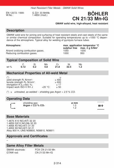
2-314
DescriptionGMAW solid wire for joining and surfacing of heat resistant steels and cast steels of the sameor similar chemical composition. Suitable for operating temperatures up to +1050 °C depen-dance of the atmosphere. Typical alloy for welding of pyrolysis furnace tubes.
Atmosphere: max. application temperatur °Csulphur free max. 2 g S/Nm3
Airand oxidizing combustion gases. 1050 1000Reducing combustion gases. 1000 950
Approvals and Certificates–
Base Materials1.4876 X10 NiCrAlTi 32 201.4859 GX10 NiCrNb 32 201.4958 X5 NiCrAlTi 31 201.4959 X8 NiCrAlTi 32 21Alloy 800 H, UNS N08800, N08810, N08811
Operating Datashielding gas: ø mmArgon + 2.5 % CO2 1.0
1.2
Mechanical Properties of All-weld Metal(*) uyield strength Re N/mm2: ≥ 400tensile strength Rm N/mm2: ≥ 600elongation A (L0=5d0) %: ≥ 17impact work ISO-V KV J +20 °C: ≥ 50
(*) u untreated, as-welded – shielding gas Argon + 2.5 % CO2
Typical Composition of Solid WireC Si Mn Cr Ni Nb
wt-% 0.12 0.2 4.8 21.8 32.5 1.2
EN 12072: 1999: G Z21 33 MnNbW.No.: 1.4850 (mod.) BÖHLER
CN 21/33 Mn-IGGMAW solid wire, high-alloyed, heat resistant
Heat Resistant Filler Metals - GMAW Solid Wires
Same Alloy Filler MetalsSMAW electrode: FOX CN 21/33 MnGTAW rod: CN 21/33 Mn-IG

2-315
DescriptionGMAW solid wire for joining and surfacing of heat resistant steels and cast steels of the sameor similar chemical composition Resistant to scaling up to +1150 °C. Typical alloy for weldingof pyrolysis furnace tubes.
Approvals and Certificates–
Base MaterialsGX40NiCrSiNb35-25 (1.4852)G-X40 NiCrSi 35 25 (1.4857)
Operating Datashielding gas: ø mmArgon + 2.5 % CO2 1.2
Mechanical Properties of All-weld Metal(*) uyield strength Re N/mm2: ≥ 400tensile strength Rm N/mm2: ≥ 600elongation A (L0=5d0) %: ≥ 8
(*) u untreated, as-welded – shielding gas Argon + 2.5 % CO2
Typical Composition of Solid WireC Si Mn Cr Ni Nb
wt-% 0.42 1.2 1.8 26 35 1.3
EN 12072:1999: G Z25 35 NbW.No.: 1.4853 BÖHLER
CN 25/35 Nb-IGGMAW solid wire, high-alloyed, heat resistant
Heat Resistant Filler Metals - GMAW Solid Wires
Similar Alloy Filler MetalsSMAW electrode: FOX CN 25/35 NbGTAW rod: CN 25/35 Nb-IG

2-316
DescriptionGMAW solid wire for joining and surfacing of heat resistant steels and cast steels of the sameor similar chemical composition Resistant to scaling up to +1180 °C. Typicall alloy for weldingof pyrolysis furnace tubes.
Approvals and Certificates–
Base MaterialsGX 45NiCrNbSiTi45-35
Operating Datashielding gas: ø mmArgon + 2.5 % CO2 1.2
Mechanical Properties of All-weld Metal(*) uyield strength Re N/mm2: ≥ 245tensile strength Rm N/mm2: ≥ 450elongation A (L0=5d0) %: ≥ 6
(*) u untreated, as-welded – shielding gas Argon + 2.5 % CO2
Typical Composition of Solid WireC Si Mn Cr Ni Nb
wt-% 0.42 1.5 1.0 35 45.5 0.8
ENISO 18274:2006: S NiZ6701 (NiCr36Fe15Nb0.8) BÖHLER CN 35/45 Nb-IG
GMAW solid wirehigh-alloyed, heat resistant
Heat Resistant Filler Metals - GMAW Solid Wires
Same Alloy Filler MetalsSMAW electrode: FOX CN 35/45 NbGTAW rod: CN 35/45 Nb-IG

Notes
2-317

2-318
2.9. Nickel-base
Objectives This section contains product information for nickel base filler metals. Themain applications of these filler metals are welding of nickel base alloys, hightemperature and creep resisting steels, heat resisting and cryogenic materi-als, dissimilar joints and low alloy problem steels. Nickel and its alloys with Cr, Cu, Fe, Mo, Co, Al and Ti offer a broad and uni-versal range of possibilities for use, e.g. for highly corrosion resisting offsho-re constructions, chemical and petrochemical plant engineering, in flue gasdesulphurisation or for sea water desalination plants as well as for high tem-perature and heat resistant applications like the boiler fabrication or the con-struction of heating ovens and furnaces.In addition some of the nickel base alloys are also suitable for cryogenicapplications down to -196 °C.
Contents
OVERVIEW ..............................................................................................320
SMAW COVERED ELECTRODES ..........................................................322
GTAW RODS............................................................................................330
GMAW SOLID WIRES .............................................................................336
GMAW FLUX CORED WIRES.................................................................342
SAW WIRE/FLUX-COMBINATIONS ........................................................344
◆
◆
Product Information

2-319
The welding of nickel alloys
Hereafter are listed the most important particulars:
Cleanliness is a top priority. Weld edge and weld area must be free of anyresidues and in particular free of grease, oil and dust.
Oxide skin must be removed approx. 10 mm on each side of the weld.
The opening angle has to be wider than on C-steel, in general 60 – 70°. Tagwelding must be done in short intervalls. The root opening has to be 2 – 3 mm wide and the root face should be approx. 2 mm high.
Electrodes have to be re-dried prior to any welding.
For most applications we recommend string bead technic. When weaving,the oscillation should be limited to 2.5 x the diameter of the electrode corewire. This does not apply to vertical up welding.
The electrode should be welded with an angle of approx. 10 – 20° and thearc should be as short as possible.
The end crater is to be filled, in the root to be grinded out. Ignition of a newelectrode should be approx. 10 mm before the last end crater, then the archas to be taken back to the end crater where the actual welding starts. Theignition points are then over welded again.
The interpass temperature should not exceed 150 °C and heat input shouldbe limited to approx. 8 – 12 KJ/cm.
If multi layer welding has to be made, each layer has to be cleaned with astainless wire brush to remove slag residues and oxide skins.
Weld surfaces can be cleaned by grinding, brushing with a stainless steelwire brush or by pickling.
◆
◆
◆
◆
◆
◆
◆
◆
◆

2-320
◆
Nickel-base Filler Metals
Overview – Standard Classifications
Böhler ENISO / DIN AWSSMAW covered electrodesFOX NIBAS 60/15 14172: E Ni 6620 (NiCr14Mo7Fe) A5.11-05: ENiCrMo-6FOX NIBAS 625 14172: E Ni 6625 (NiCr22Mo9Nb) A5.11-05: ENiCrMo-3FOX NiCr 625*FOX NIBAS 70/15 14172: E Ni 6182 (NiCr15Fe6Mn) A5.11-05: ENiCrFe-3FOX NiCr 70/15*FOX NIBAS 70/20 14172: E Ni 6082 (NiCr20Mn3Nb) A5.11-05: ENiCrFe-3(mod.)FOX NiCr 70 Nb*FOX NIBAS C 24 14172: E Ni 6059 (NiCr23Mo16) A5.11-05: ENiCrMo-13FOX NIBAS 617 14172: E Ni 6617 (NiCr22Co12Mo) A5.11-05: ENiCrCoMo-1FOX NIBAS C 276 14172: E Ni 6276 (NiCr15Mo15Fe6W4) A5.11-05: ENiCrMo-4FOX NIBAS 400 14172: E Ni 4060 (NiCu30Mn3Ti) A5.11-05: ENiCu7
GTAW rodsNIBAS 625-IG 18274: S Ni 6625 (NiCr22Mo9Nb) A5.14-05: ERNiCrMo-3NiCr 625-IG*NIBAS 70/20-IG 18274: S Ni 6082 (NiCr20Mn3Nb) A5.14-05: ERNiCr-3NiCr 70 Nb-IG*NIBAS C 24-IG 18274: S Ni 6059 (NiCr23Mo16) A5.14-05: ERNiCrMo-13NIBAS 617-IG 18274: S Ni 6617 (NiCr22Co12Mo) A5.14-05: ERNiCrCoMo-1NIBAS C 276-IG 18274: S Ni 6276 (NiCr15Mo16Fe6W4) A5.14-05: ERNiCrMo-4NIBAS 400-IG 18274: S Ni 4060 (NiCu30Mn3Ti) A5.14-05: ERNiCu7
GMAW solid wiresNIBAS 625-IG 18274: S Ni 6625 (NiCr22Mo9Nb) A5.14-05: ERNiCrMo-3NiCr 625-IG*NIBAS 70/20-IG 18274: S Ni 6082 (NiCr20Mn3Nb) A5.14-05: ERNiCr-3NiCr 70 Nb-IG*NIBAS C24-IG 18274: S Ni 6059 (NiCr23Mo16) A5.14-05: ERNiCrMo-13NIBAS 617-IG 18274: S Ni 6617 (NiCr22Co12Mo) A5.14-05: ERNiCrCoMo-1NIBAS C 276-IG 18274: S Ni 6276 (NiCr15Mo16Fe6W4) A5.14-05: ERNiCrMo-4NIBAS 400-IG 18274: S Ni 4060 (NiCu30Mn3Ti) A5.14-05: ERNiCu7
GMAW flux cored wiresNIBAS 70/20-FD 14172: Typ E Ni 6082 (NiCr20Mn3Nb) A5.34: ENiCr 3T0-4NIBAS 625-FD 14172: E Ni 6625 (NiCr22Mo9Nb) A5.34: ENiCrMo-3T0-4
SAW wire/flux-combinationNIBAS 70/20-UP/BB 44418274: S Ni 6082 (NiCr20Mn3Nb) A5.14-05: ERNiCr-3
Flux: EN760: SA-FB 2 ACNIBAS 625-UP/BB 444 18274: S Ni 6625 (NiCr22Mo9Nb) A5.14-05: ERNiCrMo-3
Flux: EN760: SA-FB 2 ACNIBAS C 24-UP/BB 444 18274: S Ni 6059 (NiCr23Mo16) A5.14-05: ERNiCrMo-13
Flux: EN760: SA-FB 2 ACNIBAS 617-UP/BB 444 18274: S Ni 6617 (NiCr22Co12Mo) A5.14-05: ERNiCrCoMo-1
Flux: EN760: SA-FB 2 ACNIBAS C276-UP/BB 444 18274: S Ni 6276 (NiCr15Mo16Fe6W4) A5.14-05: ERNiCrMo-4
Flux: EN760: SA-FB 2 AC* product name in Germany

2-321
Nickel-base Filler Metals
◆ Overview – Typical Chemical Composition
Böhler C Si Mn Cr Ni Mo Nb Ti Fe Co Ta AlSMAW covered electrodesFOX NIBAS 60/15 <0.1 <0.6 3.0 14.0 Bal. 6.5 1.0 <10.0 T 1.3FOX NIBAS 625 0.025 0.4 0.7 22.0 Bal. 9.0 3.3 0.5 ≤0.05 ≤0.4FOX NiCr 625* 0.025 0.4 0.7 22.0 Bal. 9.0 3.3 0.5 ≤0.05 ≤0.4FOX NIBAS 70/15 0.025 0.4 6.0 16.0 Bal. 2.2 + 6.0 ≤0.08 ≤0.08FOX NiCr 70/15* 0.025 0.4 6.0 16.0 Bal. 2.2 + 6.0 ≤0.08 ≤0.08FOX NIBAS 70/20 0.025 0.4 5.0 19.0 Bal. ≤1.2 2.2 + 3.0 ≤0.08FOX NiCr 70 Nb* 0.025 0.4 5.0 19.0 Bal. ≤1.2 2.2 + 3.0 ≤0.08FOX NIBAS C 24 ≤0.02 ≤0.2 0.5 22.5 Bal. 15.5 1FOX NIBAS 617 0.06 0.7 0.1 21.0 Bal. 9.0 0.3 1.0 11.0 0.9FOX NIBAS C 276 <0.02 <0.2 0.6 16.5 Bal. 16.5 5.0 T 4FOX NIBAS 400 <0.05 0.7 3.0 Bal. 0.7 1.0 0.3 Cu 29
GTAW rodsNIBAS 625-IG ≤0.02 ≤0.2 ≤0.3 22.0 Bal. 9.0 3.6 + ≤2.0NiCr 625-IG* ≤0.02 ≤0.2 ≤0.3 22.0 Bal. 9.0 3.6 + ≤2.0NIBAS 70/20-IG 0.02 ≤0.1 3.1 20.5 Bal. 2.6 + ≤1.0NiCr 70 Nb-IG* 0.02 ≤0.1 3.1 20.5 Bal. 2.6 + ≤1.0NIBAS C 24-IG ≤0.01 0.1 <0.5 23.0 Bal. 15.8 <1.0NIBAS 617-IG 0.06 0.1 0.1 21.8 Bal. 9.0 0.3 0.5 11.0 1.3NIBAS C 276-IG <0.012 0.1 16.0 Bal. 16.0 5.5 T 3.8 V 0.2NIBAS 400-IG 0.02 0.3 3.2 Bal. 2.4 1.0 <1.0 Cu 29
GMAW solid wiresNIBAS 625-IG ≤0.02 0.1 ≤0.1 22.0 Bal. 9.0 3.6 + ≤2.0NiCr 625-IG* ≤0.02 0.1 0.1 22.0 Bal. 9.0 3.6 + ≤2.0NIBAS 70/20-IG 0.03 ≤0.2 3.1 20.5 Bal. 2.5 + ≤1.0NiCr 70 Nb-IG* 0.03 ≤0.2 3.1 20.5 Bal. 2.5 + ≤1.0NIBAS C24-IG ≤0.01 ≤0.1 <0.5 23.0 Bal. 15.8 <1.0NIBAS 617-IG 0.06 0.1 0.1 21.8 Bal. 9.0 0.3 1.0 11.0 1.3NIBAS C 276-IG ≤0.01 ≤0.1 16.0 Bal. 16.0 6.0 V 0.2 T 3.5NIBAS 400-IG <0.02 0.3 3.2 Bal. 2.4 1.0 <1.0 Cu 29
GMAW flux cored wiresNIBAS 70/20-FD 0.03 0.4 3.2 19.5 Bal. 2.5 ≤2.0NIBAS 625-FD 0.05 0.4 0.4 22.0 Bal. 8.5 3.3 <5.0
SAW wire/flux-combinationNIBAS 70/20-UP 0.015 0.15 3.1 20.5 Bal. 2.6 + ≤1.0NIBAS 70/20-UP/BB 444 0.020 0.25 3.0 20.0 Bal. 2.4 + ≤1.0NIBAS 625-UP 0.015 0.15 0.2 22.0 Bal. 9.0 3.6 ≤0.5NIBAS 625-UP/BB 444 0.020 0.25 0.2 21,5 Bal. 8.5 3.2 ≤1.0NIBAS C 24-UP <0.01 <0.1 <0.5 23.0 Bal. 15.8 <1.0NIBAS C 24-UP/BB 444 <0.015 0.2 <0.5 22.5 Bal. 15.8 <1.0NIBAS 617-UP 0.06 <0.2 <0.2 21.7 Bal. 9.0 + <1.0 11.0 1.3NIBAS 617-UP/BB 444 0.06 <0.4 <0.3 21.2 Bal. 9.0 + <1.0 10.6 1.1NIBAS C276-UP ≤0.01 ≤0.1 <0.5 16.0 Bal. 16.0 <7.0 T 3.5NIBAS C276-UP/BB 444 <0.012 0.15 0.5 15.5 Bal. 16.0 <7.0 T 3.3
* product name in Germany

2-322
DescriptionThe high-nickel electrode FOX NIBAS 60/15 is especially suited for welding cold-tough nickelsteels, such as X8Ni9. High performance lime-type electrode, recovery appr. 170 %.The electrode is designated for welding with A.C., in order to avoid the magnetic arc bloweffects which occur when welding cold-tough nickel steels with D.C. It is weldable in flat, horizontal and vertical-up position. Stable arc, easy slag removal.
Approvals and CertificatesTÜV-D (10510.), CE
Base Materials9 % nickel steel base metal:X 8 Ni 9ASTM A333, A334, A353, A522, A553, K81340
Operating Datare-drying: if necessary ø mm L mm amps A250-300 °C, min. 2 h 2.5 300 70-100electrode identification: 3.2 350 100-130FOX NIBAS 60/15 NiCrMo 6 4.0 350 120-160
The weld zone must be bare and properly degreased. The electrode is welded with a slight tilt,short arc and sufficient high amperage adjustment. To avoid end crater cracks the crater mustbe filled properly and the arc drawn away to the side.
Mechanical Properties of All-weld Metal(*) uyield strength Re N/mm2: ≥ 420tensile strength Rm N/mm2: ≥ 690elongation A (L0=5d0) %: ≥ 35impact work ISO-V KV J -196 °C: ≥ 70
(*) u untreated, as-welded
Typical Composition of All-weld MetalC Si Mn Cr Mo Nb Fe T Ni
wt-% 0.05 <0.6 3.5 13.0 7.0 1 7 1.2 Bal.
ENISO 14172:2006:E Ni 6620(NiCr14Mo7Fe)
AWS 5.11-05: ENiCrMo-6BÖHLER
FOX NIBAS 60/15SMAW covered electrode, high efficiency
nickel base
Nickel-base Filler Metals – SMAW Covered Electrodes
Same Alloy Filler Metals–

DescriptionBasic electrode, core wire alloyed for welding the nickel-base alloy Inconel 625 as well as CrNiMo-steelswith high molybdenum content (e.g. "6 Mo" steels). It is also recommended for high temperature andcreep resisting steels, heat resisting and cryogenic materials, dissimilar joints, and low-alloyed problemsteels. Suitable in pressure vessel fabrication for -196 °C to +550 °C, otherwise up to the scaling resistancetemperature of +1200 °C (S-free atmosphere). Due to the weld metal embrittlement between 600 - 850 °C,this temperature range should be avoided. Highly resistant to hot cracking. Furthermore C-diffusion athigh temperature or during heat treatment of dissimilar joints is largely reduced. Extremely resistant to stress corrosion cracking and pitting (PREN 52). Thermal shock resistant, fullyaustenitic, low coefficient of thermal expansion between C-steel and austenitic CrNi (Mo)-steel. Excellent welding characteristics in all positions except vertical-down, easy slag removal, high resi-stance to porosity. Electrodes and weld metal meet highest quality requirements.
Approvals and CertificatesTÜV-D (3773.), TÜV-A (478), Statoil, LTSS, SEPROS, CE (FOX NiCr 625: TÜV-D 3773.)
Same Alloy Filler MetalsGTAW rod: NIBAS 625-IG GMAW solid wire: NIBAS 625-IG* product name in Germany GMAW flux cored wire: NIBAS 625-FD
SAW comb.: NIBAS 625-UP/BB 444
Base Materials2.4856 NiCr 22 Mo 9 Nb, 2.4858 NiCr 21 Mo, 2.4816 NiCr 15 Fe, 1.4583 X10CrNiMoNb18-12,1.4876 X 10 NiCrAlTi 32 20 H, 1.4876 X 10 NiCrAlTi 32 21, 1.4529 X1NiCrMoCuN25-20-7, X 2 CrNiMoCuN 20 18 6, 2.4641 NiCr 21 Mo 6 Cu joint welds of listed materials with non alloyand low alloy steels, e.g P265GH, P285NH, P295GH, 16Mo3, S355N, X8Ni9, ASTM A 553 Gr.1,Alloy 600, Alloy 625, Alloy 800 (H), 9 % Ni-steels
Operating Datare-drying if necessary: ø mm L mm amps A250 - 300 °C, min. 2 h 2.5 250 45 - 160electrode identification: 3.2 300 65 - 195FOX NIBAS 625 E NiCrMo-3 resp. 4.0 350 90 - 120FOX NiCr 625 E NiCrMo-3
Mechanical Properties of All-weld Metal(*) uyield strength Re N/mm2: 530 (≥ 450)tensile strength Rm N/mm2: 800 (≥ 750)elongation A (L0 = 5d0) %: 40 (≥ 330)impact work ISO-V KV J + 20 °C: 80 (≥ 365)
- 196 °C: 45 (≥ 332)(*) u untreated, as-welded
Typical Composition of All-weld MetalC Si Mn Cr Ni Mo Al Nb Co Fe
wt-% 0.025 0.4 0.7 22.0 Bal. 9.0 ≤ 0.4 3.3 ≤ 0.05 0.5
ENISO 14172:2006: E Ni 6625 (NiCr22Mo9Nb)AWS A5.11-05: ENiCrMo-3
BÖHLER FOX NIBAS 625,FOX NiCr 625*
SMAW basic electrode, nickel base
2-323
Nickel-base Filler Metals – SMAW Covered Electrodes
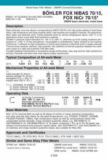
DescriptionBasic electrode, core wire alloyed, corresponding to AWS E NiCrFe-3 for high grade welding of nickel-basealloys, high-temperature and creep resisting steels, heat resisting and cryogenic materials, low-alloyed pro-blem steels and dissimilar joints. Ferritic-austenitic joints for service temperatures above +300 °C or forapplications where a post weld heat treatment is requiredSuitable in pressure vessel fabrication for -196 °C to +650 °C, otherwise up to the scaling resistance tem-perature of +1200 °C (S-free atmosphere). Insusceptible to embrittlement, highly resistant to hot cracking,furthermore, C-diffusion at high temperature or during heat treatment of dissimilar joints is largely reduced.Thermal shock resistant, stainless, fully austenitic, low coefficient of thermal expansion between the coeffi-cient values of C-steel and austenitic CrNi (Mo)-steel. Excellent welding characteristics in all positions except vertical-down, easy slag removal, high resistance toporosity. Electrode and weld metal meet highest quality requirements.
Approvals and CertificatesTÜV-D (0842.), CE (FOX NiCr 70/15: TÜV-D (0842.), KTA 1408 1 (8037.00))
Similar and Same Alloy Filler MetalsGTAW rod: NIBAS 70/20-IG GMAW solid wire: NIBAS 70/20-IG* product name in Germany GMAW flux cored wire: NIBAS 70/20-FD
SAW comb.: NIBAS 70/20-UP/BB 444
Base MaterialsNiCr 15 Fe (Inconel 600) as well as Ni-alloys of similar or same chemical composition;non alloy and low alloy steels for elevated temperatures, e.g. P235GH, P265GH, S255NB,P235GH-P355GH, 16Mo3, high temperature steels as well as constructional steels with comparable tensile strength; creep resistant austenitic steels, e.g. X8CrNiNb16-13,X8CrNiMoNb16-16, X8CrNiMoVNb16-13, Ni-steels containing 1.5% up to 5% Ni-steels; lowalloyed constructional and pressure vessel steels, also X20CrMoV12-1 and X20CrMoWV12-1on stainless and creep resistant austenitic steels; also suitable for Alloy 800.
Operating Datare-drying if necessary: ø mm L mm amps A250 - 300 °C, min. 2 h 2.5 300 45 - 175electrode identification: 3.2 300 70 - 105FOX NIBAS 70/15 E NiCrFe-3 resp. 4.0 350 95 - 130FOX NiCr 70/15 E NiCrFe-3
Mechanical Properties of All-weld Metal(*) u s1 s2yield strength Re N/mm2: 400 (≥ 360) 400 (≥ 360) 400 (≥ 360)tensile strength Rm N/mm2: 670 (≥ 600) 670 (≥ 600) 670 (≥ 600)elongation A (L0 = 5d0) %: 40 (≥ 330) 40 (≥ 330) 40 (≥ 330)impact work ISO-V KV J + 20 °C: 120 (≥ 390) 120 (≥ 380) 120 (≥ 380)
- 196 °C: 80 (≥ 332) 70 (≥ 332) 70 (≥ 332)(*) u untreated, as-welded
s1 stress relieved, 650 °C/15 h/airs2 stress relieved, 760 °C/10 h/air
Typical Composition of All-weld MetalC Si Mn Cr Ni Ti Ta Nb Co Fe
wt-% 0.025 0.4 6.0 16.0 Bal. + ≤ 0.08 2.2 ≤ 0.08 6.0
ENISO 14172:2006:E Ni 6182 (NiCr15Fe6Mn)AWS A5.11-05: ENiCrFe-3
BÖHLER FOX NIBAS 70/15,FOX NiCr 70/15*SMAW basic electrode, nickel base
2-324
Nickel-base Filler Metals – SMAW Covered Electrodes

DescriptionBasic electrode, core wire alloyed, corresponding to DIN EL-NiCr 19 Nb for high-grade welding of nickel-base alloys, high-temperature and creep resisting steels, heat resisting and cryogenic materials, low-alloy-ed problem steels and dissimilar joints. Ferritic-austenitic joints for service temperatures above +300 °C or forapplications where a post weld heat treatment is requiredSuitable in pressure vessel fabrication for -196 °C to +650 °C, otherwise up to the scaling resistance tem-perature of +1200 °C (S-free atmosphere). Insusceptible to embrittlement, highly resistant to hot cracking,furthermore, C-diffusion at high temperature or during heat treatment of dissimilar joints is largely reduced.Thermal shock resistant, stainless, fully austenitic, low coefficient of thermal expansion between the coeffi-cient values of C-steel and austenitic CrNi (Mo)-steel. Excellent welding characteristics in all positions except vertical-down, easy slag removal, high resistance toporosity, absence of undercuts, high degree of purity. Electrode and weld metal meet highest quality requi-rements.
Approvals and CertificatesTÜV-D (4697.), TÜV-A (442), Statoil, LTSS, VUZ, SEPROS, CE(FOX NiCr 70 Nb: TÜV-D (0889.), KTA 1408 1 (8039.00))
Same Alloy Filler MetalsGTAW rod: NIBAS 70/20-IG GMAW solid wire: NIBAS 70/20-IG* product name in Germany GMAW flux cored wire: NIBAS 70/20-FD
SAW comb.: NIBAS 70/20-UP/BB 444
Base Materials2.4816 Ni Cr 15 Fe, 2.4817 LC-NiCr 15 Fe, Alloy 600, Alloy 600 Lnickel and nickel alloys, low-temperature steels up to 5 % Ni-steels, unalloyed and alloyed, high-tem-perature, creep resisting, high-alloy Cr- and CrNiMo-steels particularly for joint welding of dissimilarsteels, and nickel to steel combinations; also recommended for Alloy 800.
Operating Datare-drying if necessary: ø mm L mm amps A250 - 300 °C, min. 2 h 2.5 300 40 - 170electrode identification: 3.2 300 70 - 105FOX NIBAS 70/20 resp. 4.0 350 90 - 125FOX NiCr 70 Nb 5.0 400 120 - 160
Mechanical Properties of All-weld Metal(*) u s1 s2yield strength Re N/mm2: 420 (≥ 380) 420 (≥ 380) 420 (≥ 380)tensile strength Rm N/mm2: 680 (≥ 620) 680 (≥ 620) 680 (≥ 620)elongation A (L0 = 5d0) %: 40 (≥ 330) 42 (≥ 330) 43 (≥ 330)impact work ISO-V KV J + 20 °C: 120 (≥ 390) 120 (≥ 380) 120 (≥ 380)
- 196 °C: 80 (≥ 332) 70 (≥ 332) 70 (≥ 332)(*) u untreated, as-welded
s1 stress relieved, 650 °C/15 h/airs2 stress relieved, 750 °C/3 h/air
Typical Composition of All-weld MetalC Si Mn Cr Ni Mo Ti Nb Co Fe
wt-% 0.025 0.4 5.0 19.0 Bal. ≤ 1.2 + 2.2 ≤ 0.08 3.0
ENISO 14172:2006: E Ni 6082 (NiCr20Mn3Nb)
AWS A5.11-05: ENiCrFe-3 (mod.)
BÖHLER FOX NIBAS 70/20,FOX NiCr 70 Nb*
SMAW basic electrode, nickel base
2-325
Nickel-base Filler Metals – SMAW Covered Electrodes
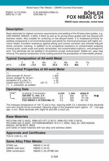
2-326
DescriptionBasic electrode for highest corrosion requirements and welding of the Ni base steel grades, e.g.UNS N06059, N06022, 2.4605, 2.4602 as well as for joining these grades with low alloyed andstainless steels. Also suitable for surfacing on low-alloyed steels. It is employed primarily forwelding components in environmental plants and plants for chemical processes with highly cor-rosive media. Excellent resistance against pitting and crevice corrosion and chloride-inducedstress corrosion cracking. In addition to its exceptional resistance to contaminated oxidatingmineral acids, acetic acids and acetic anhydrides, hot contaminated sulphuric- and phosphoricacid. The electrode can be welded in all positions except vertical-down. Stable arc, easy slagremoval.The special composition of the coating prevents the precipitation of intermetallic phases.
Approvals and CertificatesTÜV-D (10513.), CE
Base MaterialsNiCr21Mo14W (2.4602), NiMo16Cr16Ti (2.4610), NiMo16Cr15W (2.4819), NiCr23Mo16Al (2.4605), X2CrNiMnMoNbN25-18-5-4 (1.4565), Alloy 59, UNS N06059,N06022, ASTM B575, B626joint welds of listed materials with low alloy and stainless steels
Operating Datare-drying: if necessary: ø mm L mm amps A250-300 °C, min. 2 h 2.5 250 50-70electrode identification: 3.2 300 70-100FOX NIBAS C 24 ENiCrMo-13 4.0 350 90-130
The interpass temperature of 100 °C and a max. weaving width 2.5 x diameter of the electrodecore wire should not be exceeded. Opening angle of the prepared seam approx. 70 °, root gapapp. 2 mm. Weld electrode with slight filt and with a short arc.
Mechanical Properties of All-weld Metal(*) uyield strength Re N/mm2: ≥ 450tensile strength Rm N/mm2: ≥ 720elongation A (L0=5d0) %: ≥ 30impact work ISO-V KV J +20 °C: ≥ 75(*) u untreated, as-welded
Typical Composition of All-weld MetalC Si Mn Cr Mo Ni Fe
wt-% ≤ 0.02 ≤ 0.2 0.5 22.5 15.5 Bal. 1
ENISO 14172:2006: E Ni 6059(NiCr23Mo16)AWS A5.11-05: ENiCrMo-13 BÖHLER
FOX NIBAS C 24SMAW basic electrode, nickel base
Nickel-base Filler Metals – SMAW Covered Electrodes
Same Alloy Filler MetalsGTAW rod: NIBAS C 24-IGGMAW solid wire: NIBAS C 24-IGSAW combination: NIBAS C 24-UP/BB 444

2-327
DescriptionBasic electrode is suitable for joining high-temperature and similar nickel-base alloys, heat resistant austenitic and cast alloys, such as 2.4663 (NiCr21Co12Mo), 2.4851 (NiCr23Fe),1.4876 (X10 NiCrAlTi 32 20), 1.4859 (GX 10 NiCrNb 32 20). The weld metal is resistant to hot-cracking and is used for service temperatures up to +100 °C. Scale-resistance up to +1100 °C,high temperature resistant up to +1000 °C. High resistance to hot gases in oxidizing and carburized atmospheres, e.g. gas turbines, ethylene production plants. BÖHLER FOX NIBAS 617 can be welded in all positions except vertical-down. It has a stablearc. Easy slag removal.
Approvals and CertificatesCE
Base MaterialsX10NiCrAlTi32-20 (1.4876)NiCr23Fe (2.4851)GX10NiCrNb32-20 (1.4859)NiCr23Co12Mo (2.4663)Alloy 617, UNS N06617
Operating Datare-drying if necessary: ø mm L mm amps A250-300 °C, min. 2h 2.5 250 40-55electrode identification: 3.2 300 70-90FOX NIBAS 617 ENiCrCoMo-1 4.0 350 90-110
Mechanical Properties of All-weld Metal(*) uyield strength Re N/mm2: ≥ 450tensile strength Rm N/mm2: ≥ 700elongation A (L0=5d0) %: ≥ 35impact work ISO-V KV J ≥ 100
(*) u untreated, as-welded
Typical Composition of All-weld MetalC Si Mn Cr Mo Ni Co Fe Al Ti
wt-% 0.06 0.7 0.1 21 9 Bal. 11 1 0.9 0.3
ENISO 14172:2006: E Ni 6617(NiCr22Co12Mo)
AWS 5.11-05: ENiCrCoMo-1 (mod.)BÖHLER
FOX NIBAS 617SMAW basic electrode, nickel base
Nickel-base Filler Metals – SMAW Covered Electrodes
Same-alloy Filler MetalsGTAW rod: NIBAS 617-IGGMAW solid wire: NIBAS 617-IGSAW combination: NIBAS 617-UP/BB 444

2-328
DescriptionBasic electrode for welding of similar alloyed Ni base steel grades, e.g.N10276, 2.4819,NiMo16Cr15 W as well as for joining these grades with low alloyed and stainless steels. Alsosuitable for surfacing on low-alloyed steels. It is employed primarily for welding components inplants for chemical processes with highly corrosive media, but also for surfacing press tools,punches etc. which operate at high temperatures. In addition to its exceptional resistance tocontaminated mineral acids, chlorine-contaminated media, and chloride containing media, itresists strong oxidisers such as ferric and cupric chlorides and is one of the few materials whichwill resist wet chlorine gas. The electrode can be welded in all positions except vertical-down.Stable arc, easy slag removal. For avoidance of intermetallic precipitation the electrode should be welded with lowest possible heat input and minimum interpass temperature.
Approvals and CertificatesTÜV-D (10511.), CE
Base MaterialsNiMo16Cr15W (2.4819), Alloy C-276, UNS N10276, B575, B626joint welds of listed materials with low alloy and stainless steels
Operating Datare-drying if necessary: ø mm L mm amps A250-300 °C, min. 2-3 h 2.5 250 50-70electrode identification: 3.2 300 70-100FOX NIBAS C 276 ENiCrMo-4 4.0 350 90-130
The interpass temperature of 100 °C and a max. weaving width 2.5 x diameter of the electrodecore wire should not be exceeded.
Mechanical Properties of All-weld Metal(*) uyield strength Re N/mm2: ≥ 450tensile strength Rm N/mm2: ≥ 720elongation A (L0=5d0) %: ≥ 30impact work ISO-V KV J ≥ 70
(*) u untreated, as-welded
Typical Composition of All-weld MetalC Si Mn Cr Mo Ni T Fe
wt-% < 0.02 < 0.2 0.6 16.5 16.5 Bal. 4 5
ENISO 14172:2006:E Ni 6276(NiCr15Mo15Fe6W4)
AWS 5.11-05: ENiCrMo-4BÖHLER
FOX NIBAS C 276SMAW basic electrode, nickel base
Nickel-base Filler Metals – SMAW Covered Electrodes
Same-alloy Filler MetalsGTAW rod: NIBAS C 276-IGGMAW solid wire: NIBAS C276-IGSAW combination: NIBAS C276-UP/BB 444
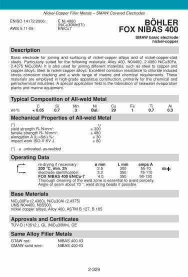
2-329
DescriptionBasic electrode for joining and surfacing of nickel-copper alloys and of nickel-copper-cladsteels. Particularly suited for the following materials: Alloy 400, N04400, 2.4360 NiCu30Fe,2.4375 NiCu30Al. It is also used for joining different materials, such as steel to copper and copper alloys, steel to nickel-copper alloys. Excellent corrosion resistance to chloride inducedstress corrosion cracking and a wide range of marine and chemical requirements. These materials are employed in high-grade apparatus construction, primarily for the chemical andpetrochemical industries. A special application field is the fabrication of seawater evaporationplants and marine equipment.
Approvals and CertificatesTÜV-D (10512.), GL (NiCu30Mn), CE
Base MaterialsNiCu30Fe (2.4360), NiCu30Al (2.4375) UNS N04400, N05500,nickel copper alloys, Alloy 400, ASTM B 127, B 165
Operating Datare-drying if necessary: ø mm L mm amps A200 °C, min. 2h 2.5 300 55-70electrode identification: 3.2 350 75-110FOX NIBAS 400 ENiCu-7 4.0 350 90-130Thorough cleaning of the weld zone is essential to avoid porosity. Angle of seam about 70 °, weld string beads if possible.
Mechanical Properties of All-weld Metal(*) uyield strength Re N/mm2: ≥ 300tensile strength Rm N/mm2: ≥ 480elongation A (L0=5d0) %: ≥ 30impact work ISO-V KV J ≥ 80
(*) u untreated, as-welded
Typical Composition of All-weld MetalC Si Mn Ni Cu Fe Ti Al
wt-% < 0.05 0.7 3 Bal. 29 1 0.7 0.3
ENISO 14172:2006: E Ni 4060(NiCu30Mn3Ti)
AWS 5.11-05: ENiCu7BÖHLER
FOX NIBAS 400SMAW basic electrode
nickel-copper
Nickel-Copper Filler Metals – SMAW Covered Electrodes
Same Alloy Filler MetalsGTAW rod: NIBAS 400-IGGMAW solid wire: NIBAS 400-IG

DescriptionGTAW rod for high-quality joint welding of high-molybdenum nickel-base alloys (e.g. Inconel 625 and Incoloy825) as well as of CrNiMo steels with high Mo-content (e.g. "6Mo" steels). Additionally this brand is recom-mended for high-temperature or creep resisting, heat resisting and cryogenic materials, for low-alloy problem steels and joining dissimilar materials. Can be used for pressure vessel fabrication for service temperatures from -196 °C to +550 °C, otherwiseup to scaling resistance limit of +1200 °C (S-free atmosphere. Due to the weld metal embrittlement between+600 - 850 °C, this temperature range should be avoided. Highly resistant to hot cracking; furthermore,C-diffusion at high temperatures, or during heat treatment of dissimilar steels is largely inhibited. Extremely resistant to stress corrosion cracking and pitting corrosion (PREN 52). Resistant to thermalshocks, stainless, fully austenitic. Low coefficient of thermal expansion (between C-steels and austeniticCrNi (Mo) steel). TIG-rod and deposit satisfy the highest quality standards.
Approvals and CertificatesTÜV-D (4324.), TÜV-A (436), Statoil, SEPROZ, CE (NiCr 625-IG: TÜV-D (3938.))
Same Alloy Filler MetalsSMAW electrode: FOX NIBAS 625 GMAW solid wire: NIBAS 625-IG*product name in Germany GMAW flux cored wire: NIBAS 625-FD
SAW comb.: NIBAS 625-UP/BB 444
Base materials2.4856 NiCr 22 Mo 9 Nb, 2.4858 NiCr 21 Mo, 2.4816 NiCr 15 Fe, 1.4583 X10CrNiMoNb18-12,1.4876 X 10 NiCrAlTi 32 20 H, 1.4876 X 10 NiCrAlTi 32 20, 1.4529 X1NiCrMoCuN25-20-7, X 2 CrNiMoCuN 20 18 6, 2.4641 NiCr 21 Mo 6 Cu joint welds of listed materials with non alloyand low alloy steels, e.g P265GH, P285NH, P295GH, 16Mo3, S355N, X8Ni9, ASTM A 553 Gr.1,Alloy 600, Alloy 625, Alloy 800 (H), 9 % Ni-steels
Operating Datashielding gases: 100 % Argon ø mm
Ar + He mixture gases 1.6rod marking: 2.0
front: 2.4831 2.4back: ERNiCrMo-3
Mechanical Properties of All-weld Metal(*) uyield strength Re N/mm2: 540 (≥ 460)tensile strength Rm N/mm2: 800 (≥ 740)elongation A (L0 = 5d0) %: 38 (≥ 335)impact work ISO-V KV J + 20 °C: 160 (≥ 120)
- 196 °C: 130 (≥ 100)(*) u untreated, as-welded – shielding gas Argon
Typical Composition of Welding RodC Si Mn Cr Ni Mo Nb Fe Ti
wt-% ≤ 0.02 0.1 0.1 22 Bal. 9.0 3.6 ≤ 0.5 +
ENISO 18274:2006:S Ni 6625 (NiCr22Mo9Nb)
AWS A5.14-05: ERNiCrMo-3W.Nr.: 2.4831
BÖHLER NIBAS 625-IG,NiCr 625-IG*
GTAW rod, nickel base
2-330
Nickel-base Filler Metals - GTAW Rods

DescriptionGTAW rod for welding of nickel-base alloys, high-temperature and creep resisting steels, heatresisting and cryogenic materials, low-alloyed problem steels and dissimilar joints. Ferritic-aus-tenitic joints for service temperatures above + 300 °C or for applications where a post weld heattreatment is requiredSuitable in pressure vessel fabrication from -196 °C to +550 °C, otherwise resistant to scalingup to +1200 °C (S-free atmosphere). Not susceptible to embrittlement, C-diffusion at elevatedtemperatures largely inhibited. Resistant to thermal shocks, corrosion resistant, fully austenitic, low coefficient of thermalexpansion. between the coefficient values of C-steel and austenitic CrNi (Mo)-steel.Both the TIG-rod and the weld deposit satisfy highest quality requirements.
Approvals and CertificatesTÜV-D (4328.), TÜV-A (434), Statoil, SEPROS, CE (NiCr 70 Nb-IG TÜV-D (0891.), KTA 1408 1 (8035.00))
Same Alloy Filler MetalsSMAW electrode: FOX NIBAS 70/20 GMAW solid wire: NIBAS 70/20-IG*product name in Germany GMAW flux cored wire: NIBAS 70/20-FD
SAW comb.: NIBAS 70/20-UP/BB 444
Base Materials2.4816 Ni Cr 15 Fe, 2.4817 LC-NiCr 15 Fe, Alloy 600, Alloy 600 L. nickel and nickel alloys, low-tem-perature steels up to 5 % Ni-steels, unalloyed and alloyed, high-temperature, creep resisting, high-alloy Cr- and CrNiMo-steels particularly for joint welding of dissimilar steels, and nickel to steelcombinations; also recommended for Alloy 800.
Operating Datashielding gases: 100 % Argon ø mm
Ar + He mixture gases 1.6rod marking: 2.0
front: 2.4806 2.4back: ERNiCr-3
Mechanical Properties of All-weld Metal(*) uyield strength Re N/mm2: 440 (≥ 400)tensile strength Rm N/mm2: 680 (≥ 620)elongation A (L0 = 5d0) %: 42 (≥ 335)impact work ISO-V KV J + 20 °C: 190 (≥ 150)
- 196 °C: 100 (≥ 332)(*) u untreated, as-welded – shielding gas Argon
Typical Composition of Welding RodC Si Mn Cr Ni Ti Nb Fe
wt-% 0.02 0.1 3.1 20.5 Bal. + 2.6 ≤ 1
ENISO 18274:2006: S Ni 6082 (NiCr20Mn3Nb)AWS A5.14-05: ERNiCr-3W.Nr.: 2.4806
BÖHLER NIBAS 70/20-IG,NiCr 70 Nb-IG*
GTAW rod, nickel base
2-331
Nickel-base Filler Metals - GTAW Rods

2-332
DescriptionGTAW rod for highest corrosion requirements and welding of the Ni base steel grades, e.g.UNS N06059, N06022, 2.4605, 2.4602 as well as for joining these grades with low alloyed andstainless steels. Also suitable for surfacing on low-alloyed steels.. It is employed primarily forwelding components in environmental plants and plants for chemical processes with highly cor-rosive media. Excellent resistance against pitting and crevice corrosion and chloride-inducedstress corrosion cracking. In addition to its exceptional resistance to contaminated oxidatingmineral acids, acetic acids and acetic anhydrides, hot contaminated sulphuric- and phosphoricacid.
Approvals and CertificatesTÜV-D (10523.), CE
Base MaterialsNiCr21Mo14W (2.4602), NiMo16Cr16Ti (2.4610), NiMo16Cr15W (2.4819), NiCr23Mo16Al (2.4605), X2 CrNiMnMoNbN25-18-5-4 (1.4565), Alloy 59,UNS, N06059; N06022, B575, B626 joint welds of listed materials with low alloy and stainless steels
Operating Datashielding gases: ø mm100 % Argon 1.6Ar + He mixture gases 2.0rod marking: 2.4front: 2.4607 3.2back: ERNiCrMo-13Weld with possibly low heat input and low interpass temperature.
Mechanical Properties of All-weld Metal(*) uyield strength Re N/mm2: ≥ 450tensile strength Rm N/mm2: ≥ 700elongation A (L0=5d0) %: ≥ 35impact work ISO-V KV J ≥ 120
(*) u untreated, as-welded – shielding gas Argon
Typical Composition of Welding RodC Si Mn Cr Mo Ni Fe
wt-% ≤ 0.01 ≤ 0.1 < 0.5 23 15.8 Bal. < 1
ENISO 18274:2006: S Ni 6059(NiCr23Mo16)
AWS 5.14-05: ERNiCrMo-13W.Nr.: 2.4607
BÖHLERNIBAS C 24-IG
GTAW rod, nickel base
Nickel-base Filler Metals - GTAW Rods
Same Alloy Filler MetalsSMAW: FOX NIBAS C 24GMAW solid wire: NIBAS C24-IGSAW combination: NIBAS C24-UP/BB 444

2-333
DescriptionGTAW rod for joining high-temperature and similar nickel-base alloys, heat resistant austeniticand cast alloys, such as 2.4663 (NiCr21Co12Mo), 2.4851 (NiCr23Fe), 1.4876 (X10 NiCrAlTi 3220), 1.4859 (GX 10 NiCrNb 32 20). The weld metal is resistant to hot-cracking and is used forservice temperatures up to +1100 °C. Scale-resistance up to +1100 °C, high temperature resistant up to +1000 °C. High resistance to hot gases in oxidizing and carburized atmospheres, e.g. gas turbines, ethylene production plants.
Approvals and CertificatesTÜV-D (10551.), CE
Base MaterialsX10NiCrAlTi32-20 (1.4876)NiCr23Fe (2.4851)GX10NiCrNb32-20 (1.4859)NiCr23Co12Mo (2.4663)Alloy 617, UNS N06617
Operating Datashielding gases: ø mm100 % Argon / Ar + He mixture gases 2.0rod marking: 2.4front: 2.4627back: ERNiCrCoMo-1
Mechanical Properties of All-weld Metal(*) uyield strength Re N/mm2: ≥ 450tensile strength Rm N/mm2: ≥ 700elongation A (L0=5d0) %: ≥ 30impact work ISO-V KV J ≥ 60
(*) u untreated, as-welded – shielding gas Argon
Typical Composition of Welding RodC Si Mn Cr Mo Ni Co Al Ti Fe
wt-% 0.06 0.1 0.1 21.8 9 Bal. 11 1.3 0.3 0.5
ENISO 18274:2006: S Ni 6617(NiCr22Co12 Mo)
AWS 5.14-05: ERNiCrCoMo-1W.Nr.: 2.4627
BÖHLERNIBAS 617-IG
GTAW rod, nickel base
Nickel-base Filler Metals - GTAW Rods
Same Alloy Filler MetalsSMAW: FOX NIBAS 617GMAW wire: NIBAS 617-IGSAW combination: NIBAS 617-UP/BB 444

2-334
DescriptionGTAW rod for welding of similar alloyed Ni base steel grades, e.g. N10276, 2.4819,NiMo16Cr15 W as well as for joining these grades with low alloyed and stainless steels. Alsosuitable for surfacing on low-alloyed steels. steels. It is employed primarily for welding components in plants for chemical processes with highly corrosive media, but also for surfacingpress tools, punches etc. which operate at high temperatures. In addition to its exceptional resistance to contaminated mineral acids, chlorine-contaminated media, and chloride contai-ning media, it resists strong oxidisers such as ferric and cupric chlorides and is one of the fewmaterials which will resist wet chlorine gas.
Approvals and CertificatesTÜV-D (10521.), CE
Base MaterialsNiMo16Cr15W (2.4819), Alloy C-276, UNS N10276, B575, B626joint welds of listed materials with low alloy and stainless steels
Operating Datashielding gases: ø mm100 % Argon 2.0Ar + He mixture gases 2.4rod marking:front: 2.4886back: ERNiCrMo-4Weld with possibly low heat input and low interpass temperature in order to avoid intermetallic precipitations.
Mechanical Properties of All-weld Metal(*) uyield strength Re N/mm2: ≥ 450tensile strength Rm N/mm2: ≥ 750elongation A (L0=5d0) %: ≥ 30impact work ISO-V KV J ≥ 90
(*) u untreated, as-welded – shielding gas Argon
Typical Composition of Welding RodC Si Cr Mo Ni T Fe V
wt-% < 0.012 0.1 16 16 Bal. 3.8 5.5 0.2
ENISO 18274:2006: S Ni 6276(NiCr15Mo16Fe6W4)
AWS 5.14-05: ERNiCrMo-4W.Nr.: 2.4886
BÖHLERNIBAS C 276-IG
GTAW rod, nickel base
Nickel-base Filler Metals - GTAW Rods
Same Alloy Filler MetalsSMAW: FOX NIBAS C 276GMAW solid wire: NIBAS C276-IGSAW combination: NIBAS C276-UP/BB 444

2-335
DescriptionGTAW rod for joining and surfacing of nickel-copper alloys and of nickel-copper-clad steels.Particularly suited for the following materials: alloy 400, N04400, 2.4360 NiCu30Fe, 2.4375NiCu30Al. It is also used for joining different materials, such as steel to copper and copperalloys, steel to nickel-copper alloys. Excellent corrosion resistance to chloride induced stresscorrosion cracking and a wide range of marine and chemical requirements. These materials areemployed in high-grade apparatus construction, primarily for the chemical and petrochemicalindustries. A special application field is the fabrication of seawater evaporation plants and marine equipment.
Approvals and CertificatesTÜV-D (10519.), CE
Base MaterialsNiCu30Fe (2.4360), NiCu30Al (2.4375) UNS N04400, N05500,nickel copper alloys, Alloy 400, ASTM B 127, B 165
Operating Datashielding gases: ø mm100 % Argon / Ar + He mixture gases 1.6rod marking: 2.0front: 2.4377 2.4back: ERNiCu7Weld with possibly low heat input and low interpass temperature.
Mechanical Properties of All-weld Metal(*) uyield strength Re N/mm2: ≥ 300tensile strength Rm N/mm2: ≥ 500elongation A (L0=5d0) %: ≥ 35impact work ISO-V KV J ≥ 150
(*) u untreated, as-welded – shielding gas Argon
Typical Composition of Welding RodC Si Mn Ni Cu Ti Fe Al
wt-% 0.02 0.3 3.2 Bal. 30 2.4 1 < 1.0
ENISO 18274:2006: S Ni 4060(NiCu30Mn3Ti)
AWS 5.14-05: ERNiCu7W.Nr.: 2.4377
BÖHLER NIBAS 400-IG
GTAW rod, nickel copper
Nickel-Copper Filler Metals - GTAW Rods
Same Alloy Filler MetalsSMAW: FOX NIBAS 400GMAW solid wire: NIBAS 400-IG

DescriptionGMAW solid wire for high-quality joint welding of nickel-base alloys like Inconel 625 and Incoloy 825 as wellas of CrNiMo stainless steels with high Mo-content (e.g. "6Mo" steels). Additionally it is recommended forhigh-temperature or creep resisting, heat resisting and cryogenic materials, joining of dissimilar steels, andalso for problem steels. Can be used for pressure vessel fabrication for service temperatures in the -196 °C to +550 °C range, other-wise up to scaling resistance limit of +1200°C (S-free atmosphere). Due to the weld metal embrittlementbetween +600 - 850 °C, this temperature range should be avoided. Highly resistant to hot cracking;furthermore, C-diffusion at high service temperatures or during post weld heat treatment of dissimilar steelsis largely inhibited. Extremely resistant to stress corrosion cracking and pitting (PREN 52). Resistant to thermal shocks, fullyaustenitic. Low coefficient of thermal expansion (between C-steels and austenitic CrNi (Mo) steel). Wire and weld metal satisfy highest quality standards.
Approvals and CertificatesTÜV-D (4323.), TÜV-A (437), Statoil, SEPROZ, CE (NiCr 625-IG: TÜV-D (3937.))
Same Alloy Filler MetalsSMAW electrode: FOX NIBAS 625 GTAW rod: NIBAS 625-IG* product name in Germany GMAW flux cored wire: NIBAS 625-FD
SAW comb.: NIBAS 625-UP/BB 444
Base Materials2.4856 NiCr 22 Mo 9 Nb, 2.4858 NiCr 21 Mo, 2.4816 NiCr 15 Fe, 1.4583 X10CrNiMoNb18-12,1.4876 X 10 NiCrAlTi 32 20 H, 1.4876 X 10 NiCrAlTi 32 20, 1.4529 X1NiCrMoCuN25-20-7, X 2 CrNiMoCuN 20 18 6, 2.4641 NiCr 21 Mo 6 Cu joint welds of listed materials with non alloyand low alloy steels, e.g P265GH, P285NH, P295GH, 16Mo3, S355N, X8Ni9, ASTM A 553 Gr.1,Alloy 600, Alloy 625, Alloy 800, 9 % Ni-steels
Operating Datashielding gases: ø mmArgon + 40% He 1.0Ar + He + small amounts of active gas 1.2Welding with puls technic will be advantageous.
Mechanical Properties of All-weld Metal(*) uyield strength Re N/mm2: 510 (≥ 460)tensile strength Rm N/mm2: 780 (≥ 740)elongation A (L0 = 5d0) %: 40 (≥ 325)impact work ISO-V KV J + 20 °C: 130 (≥ 100)
- 196 °C: 80 (≥ 332)(*) u untreated, as-welded – shielding gas Argon + 40 % Helium
Typical Composition of Solid WireC Si Mn Cr Ni Mo Nb Fe Ti
wt-% ≤ 0.02 0.1 0.1 22 Bal. 9.0 3.6 ≤ 0.5 +
ENISO 18274:2006:S Ni 6625 (NiCr22Mo9Nb)
AWS A5.14-05: ERNiCrMo-3W.Nr.: 2.4831
BÖHLER NIBAS 625-IG,NiCr 625-IG*
GMAW solid wire, nickel base
2-336
Nickel-base Filler Metals - GMAW Solid Wires

2-337
DescriptionGMAW solid wire for welding of nickel-base alloys, high-temperature and creep resisting steels,heat resisting and cryogenic materials, low-alloyed problem steels and dissimilar joints. Ferritic-austenitic joints for service temperatures above +300 °C or for applications where a post weldheat treatment is required. Suitable for pressure vessel fabrication for the service temperaturerange -196 °C to +550 °C, otherwise resistant to scaling up to +1200 °C (S-free atmosphere). Not susceptible to embrittlement, C-diffusion at elevated temperatures largely inhibited.Resistant to thermal shocks, corrosion resistant, fully austenitic. Low coefficient of thermalexpansion (between C-steels and austenitic CrNi (Mo) steel). Both the wire and the deposit satisfy the highest quality requirements.
Approvals and CertificatesTÜV-D (4327.), TÜV-A (435), Statoil, SEPROZ, CE (NiCr 70 Nb-IG TÜV-D (0890.))
Same Alloy Filler MetalsSMAW electrode: FOX NIBAS 70/20 GTAW rod: NIBAS 70/20-IGGMAW flux cored wire: NIBAS 70/20-FD SAW comb.: NIBAS 70/20-UP / BB 444* product name in Germany
Base Materials2.4816 Ni Cr 15 Fe, 2.4817 LC-NiCr 15 Fe, Alloy 600, Alloy 600 Lnickel and nickel alloys, low-temperature steels up to X8Ni9, unalloyed and alloyed, high-temperature,creep resisting, high-alloy Cr- and CrNiMo-steels particularly for joint welding of dissimilar steels, andnickel to steel combinations; also recommended for Alloy 800 (H).
Operating Datashielding gases: ø mmArgon + 40 % He 0.8Ar + He + small quantities active gas 1.0
1.2Welding with puls technic will be advantageous.
Mechanical Properties of All-weld Metal(*) uyield strength Re N/mm2: 420 (≥ 400)tensile strength Rm N/mm2: 680 (≥ 620)elongation A (L0 = 5d0) %: 40 (≥ 335)impact work ISO-V KV J + 20 °C: 160 (≥ 150)
- 196 °C: 80 (≥ 332)(*) u untreated, as-welded – shielding gas Argon + 40 % Helium
Typical Composition of Solid WireC Si Mn Cr Ni Ti Nb Fe
wt-% 0.02 0.1 3.1 20.5 Bal. + 2.6 ≤ 1
ENISO 18274:2006: S Ni 6082 (NiCr20Mn3Nb)AWS A5.14-05: ERNiCr-3W.Nr.: 2.4806
BÖHLER NIBAS 70/20-IG,NiCr 70 Nb-IG*
GMAW solid wire, nickel base
Nickel-base Filler Metals - GMAW Solid Wires

2-338
DescriptionGMAW solid wire for highest corrosion requirements and welding of the Ni base steel grades,e.g. UNS N06059, N06022, 2.4605, 2.4602 as well as for joining these grades with low alloy-ed and stainless steels. Also suitable for surfacing on low-alloyed steels. It is employed prima-rily for welding components in environmental plants and plants for chemical processes with hig-hly corrosive media. Excellent resistance against pitting and crevice corrosion and chloride-induced stress corrosion cracking. In addition to its exceptional resistance to contaminated oxidating mineral acids, acetic acids and acetic anhydrides, hot contaminated sulphuric- andphosphoric acid.
Approvals and CertificatesTÜV-D (10522.), CE
Base MaterialsNiCr21Mo14W (2.4602), NiMo16Cr16Ti (2.4610), NiMo16Cr15W (2.4819), NiCr23Mo16Al(2.4605), X2 CrNiMnMoNbN25-18-5-4 (1.4565), Alloy 59,UNS, N06059; N06022, B575, B626 joint welds of listed materials with low alloy and stainless steels
Operating Datashielding gases: ø mm100 % Argon 1.0M 11 + 28 % He 1.2Weld with possibly low heat input and low interpass temperature.
Mechanical Properties of All-weld Metal(*) uyield strength Re N/mm2: ≥ 420tensile strength Rm N/mm2: ≥ 700elongation A (L0=5d0) %: ≥ 35impact work ISO-V KV J ≥ 100
(*) u untreated, as-welded – shielding gas Argon
Typical Composition of Solid WireC Si Mn Cr Mo Ni Fe
wt-% ≤ 0.01 ≤ 0.1 < 0.5 23 15.8 Bal. < 1
ENISO 18274:2006: S Ni 6059(NiCr23Mo16)
AWS 5.14-05: ERNiCrMo-13W.Nr.: 2.4607
BÖHLERNIBAS C 24-IG
GMAW solid wirenickel base
Nickel-base Filler Metals - GMAW Solid Wires
Same Alloy Filler MetalsSMAW: FOX NIBAS C 24GTAW rod: NIBAS C24-IGSAW combination: NIBAS C24-UP/BB 444
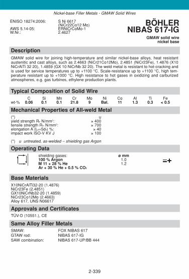
2-339
DescriptionGMAW solid wire for joining high-temperature and similar nickel-base alloys, heat resistant austenitic and cast alloys, such as 2.4663 (NiCr21Co12Mo), 2.4851 (NiCr23Fe), 1.4876 (X10NiCrAlTi 32 20), 1.4859 (GX 10 NiCrNb 32 20). The weld metal is resistant to hot-cracking andis used for service temperatures up to +1100 °C. Scale-resistance up to +1100 °C, high tem-perature resistant up to +1000 °C. High resistance to hot gases in oxidizing and carburizedatmospheres, e.g. gas turbines, ethylene production plants.
Approvals and CertificatesTÜV-D (10551.), CE
Base MaterialsX10NiCrAlTi32-20 (1.4876)NiCr23Fe (2.4851)GX10NiCrNb32-20 (1.4859)NiCr23Co12Mo (2.4663)Alloy 617, UNS N06617
Operating Datashielding gases: ø mm100 % Argon 1.0M 11 + 28 % He 1.2Ar + 30 % He + 0.5 % CO2
Mechanical Properties of All-weld Metal(*) uyield strength Re N/mm2: ≥ 400tensile strength Rm N/mm2: ≥ 700elongation A (L0=5d0) %: ≥ 40impact work ISO-V KV J ≥ 100
(*) u untreated, as-welded – shielding gas Argon
Typical Composition of Solid WireC Si Mn Cr Mo Ni Co Al Ti Fe
wt-% 0.06 0.1 0.1 21.8 9 Bal. 11 1.3 0.3 < 0.5
ENISO 18274:2006: S Ni 6617(NiCr22Co12 Mo)
AWS 5.14-05: ERNiCrCoMo-1W.Nr.: 2.4627
BÖHLERNIBAS 617-IG
GMAW solid wirenickel base
Nickel-base Filler Metals - GMAW Solid Wires
Same Alloy Filler MetalsSMAW: FOX NIBAS 617GTAW rod: NIBAS 617-IGSAW combination: NIBAS 617-UP/BB 444

2-340
DescriptionGMAW solid wire for welding of similar alloyed Ni base steel grades, e.g.N10276, 2.4819,NiMo16Cr15 W as well as for joining these grades with low alloyed and stainless steels andsurfacing on low-alloyed steels. It is employed primarily for welding components in plants forchemical processes with highly corrosive media, but also for surfacing press tools, punches etc.which operate at high temperatures. In addition to its exceptional resistance to contaminatedmineral acids, chlorine-contaminated media, and chloride containing media, it resists strongoxidisers such as ferric and cupric chlorides and is one of the few materials which will resist wetchlorine gas.
Approvals and CertificatesTÜV-D (10520.), CE
Base MaterialsNiMo16Cr15W (2.4819), Alloy C-276, UNS N10276, B575, B626joint welds of listed materials with low alloy and stainless steels
Operating Datashielding gases: ø mm100 % Argon 1.2M 11 + 28 % HeWeld with possibly low heat input and low interpass temperature in order to avoid intermetallic precipitations.
Mechanical Properties of All-weld Metal(*) uyield strength Re N/mm2: ≥ 450tensile strength Rm N/mm2: ≥ 750elongation A (L0=5d0) %: ≥ 30impact work ISO-V KV J ≥ 90
(*) u untreated, as-welded – shielding gas Argon
Typical Composition of Solid WireC Si Cr Mo Ni T Fe V
wt-% ≤ 0.01 ≤ 0.1 16 16 Bal. 3.5 6 0.2
ENISO 18274:2006: S Ni 6276(NiCr15Mo16Fe6W4)
AWS 5.14-05: ERNiCrMo-4W.Nr.: 2.4886
BÖHLERNIBAS C 276-IG
GMAW solid wirenickel base
Nickel-base Filler Metals - GMAW Solid Wires
Same Alloy Filler MetalsSMAW: FOX NIBAS C 276GTAW rod: NIBAS C276-IGSAW combination: NIBAS C276-UP/BB 444

2-341
DescriptionGMAW solid wire for joining and surfacing of nickel-copper alloys and of nickel-copper-cladsteels. Particularly suited for the following materials: alloy 400, N04400, 2.4360 NiCu30Fe,2.4375 NiCu30Al. It is also used for joining different materials, such as steel to copper and copper alloys, steel to nickel-copper alloys. Excellent corrosion resistance to chloride inducedstress corrosion cracking and a wide range of marine and chemical requirements. These materials are employed in high-grade apparatus construction, primarily for the chemical andpetrochemical industries. A special application field is the fabrication of seawater evaporationplants and marine equipment.
Approvals and CertificatesTÜV-D (10518.), GL (NiCu30MnTi), CE
Base MaterialsNiCu30Fe (2.4360), NiCu30Al (2.4375) UNS N04400, N05500,nickel copper alloys, Alloy 400, ASTM B 127, B 165
Operating Datashielding gases: ø mm100 % Argon 1.0M 11 + 28 % He 1.2Weld with possibly low heat input and low interpass temperature.
Mechanical Properties of All-weld Metal(*) uyield strength Re N/mm2: ≥ 300tensile strength Rm N/mm2: ≥ 500elongation A (L0=5d0) %: ≥ 35impact work ISO-V KV J ≥ 150
(*) u untreated, as-welded – shielding gas Argon
Typical Composition of Solid WireC Si Mn Ni Cu Ti Fe Al
wt-% < 0.02 0.3 3.2 Bal. 29 2.4 1 < 1.0
ENISO 18274:2006: S Ni 4060(NiCu30Mn3Ti)
AWS 5.14-05: ERNiCu7W.Nr.: 2.4377
BÖHLER NIBAS 400-IG
GMAW solid wirenickel copper
Nickel-base Filler Metals - GMAW Solid Wires
Same Alloy Filler MetalsSMAW: FOX NIBAS 400GTAW rod: NIBAS 400-IG

DescriptionRutile flux cored wire with basic elements, especially designed for downhand and horizontal welding positions. The easy operation and the high rate of deposition of Böhler NIBAS 70/20-FD leads to high pro-ductivity, with excellent operating characteristic, self releasing slag, almost no spatter formation and temperdiscoloration, smooth weld finish, good side wall wetting and safe penetration. Beside considerable savingsin time and money and little demand for cleaning and pickling, Böhler also guarantees a high quality leveland a reduction of welding defects.Suitable for high quality weld joints of nickelbase alloys, high temperature and creep resisting materials, scaling resistant and low-temperature steels, dissimilar joints and difficult weldable steel grades. Ferritic-austenitic joints for service temperatures above +300 °C or for applications where a post weld heat treat-ment is required.Suitable for pressure vessel fabrication for the service temperature range -196 °C to +550 °C, otherwiseresistant to scaling up to +1200 °C (S-free atmosphere). Not susceptible to embrittlement, C-diffusion at elevated temperatures largely inhibited. Resistant to thermalshocks, corrosion resistant, fully austenitic, low coefficient of thermal expansion. Out of position weldability is limited, in special cases pulse arc welding shows advantages.
Approvals and CertificatesTÜV-D (10298.), CE
Same Alloy Filler Metals
SMAW electrode: FOX NIBAS 70/20 GTAW rod: NIBAS 70/20-IGGMAW solid wire: NIBAS 70/20-IG
Base Materials2.4816 Ni Cr 15 Fe, 2.4817 LC-NiCr 15 Fe, Alloy 600, Alloy 600 Lnickel and nickel alloys, low-temperature steels up to 5 % Ni-steels, unalloyed and alloyed, high-tempe-rature, creep resisting, high-alloy Cr- and CrNiMo-steels particularly for joint welding of dissimilar steels,and nickel to steel combinations; also recommended for Alloy 800 (H).
Operating Datare-drying if necessary: ø mm L mm amps AArgon + 15-25 % CO2 1.2 130 - 260 24 - 36
1.6 150 - 350 23 - 32welding with standard GMAW-facilities possible, slightly trailing torch position (angel appr. 80 °).The gas flow should be 15 - 18 l/min.
Mechanical Properties of All-weld Metal(*) u yield strength Re N/mm2: 400 (≥ 360)tensile strength Rm N/mm2: 650 (≥ 600)elongation A (L0 = 5d0) %: 39 (≥ 330)impact work ISO-V KV J + 20 °C: 135 (≥ 110)
- 196 °C: 110 (≥ 380)(*) u untreated, as-welded – shielding gas Argon + 20 % CO2
Typical Composition of All-weld MetalC Si Mn Cr Ni Nb Fe
wt-% 0.03 0.4 3.2 19.5 Bal. 2.5 ≤ 2.0
ENISO 14172:2006: Typ Ni 6082 (NiCr20Mn3Nb)
AWS A5.34: ENiCr-3TO-4
BÖHLER NIBAS 70/20-FDGMAW flux cored wire, nickel base
2-342
Nickel-base Filler Metals - GMAW flux cored wire

2-343
DescriptionRutile flux cored wire for high-quality joint welding of nickel-base alloys like Alloy 625 and Alloy825 as well as of CrNiMo stainless steels with high Mo-content (e.g. "6Mo" steels). Additionallyit is recommended for high-temperature or creep resisting, heat resisting and cryogenic mate-rials, joining of dissimilar steels, and also for problem steels. Can be used for pressure vesselfabrication for service temperatures in the -196 °C to +550 °C range, otherwise up to scalingresistance limit of +1200 °C (S-free atmosphere). Due to the weld metal embrittlement between600-850 °C, this temperature range should be avoided. Highly resistant to hot cracking; furthermore, C-diffusion at high service temperatures or during post weld heat treatment of dis-similar steels is largely inhibited. Extremely resistant to stress corrosion cracking and pitting(PREN 52). Resistant to thermal shocks, fully austenitic. Low coefficient of thermal expansion(between C-steels and austenitic CrNi (Mo) steel). Good position weldability.
Approvals and Certificates–
Same Alloy Filler MetalsSMAW electrode: FOX NIBAS 625 GMAW solid wire: NIBAS 625-IGGTAW rod: NIBAS 625-IG
Base Materials2.4856 NiCr 22 Mo 9 Nb, 2.4858 NiCr 21 Mo, 2.4816 NiCr 15 Fe, 1.4583 X10CrNiMoNb18-12, 1.4876 X 10 NiCrAlTi 32 20 H, 1.4876 X 10 NiCrAlTi 32 20, 1.4529 X1NiCrMoCuN25-20-7, X 2 CrNiMoCuN 20 18 6, 2.4641 NiCr 21 Mo 6 Cu,joint welds of listed materials with non alloy and low alloy steels, e.g P265GH, P285NH,P295GH, 16Mo3, S355N, X8Ni9, ASTM A 553 Gr.1, Alloy 600, Alloy 625, Alloy 800
Operating Datashielding gases: ø mm Amperage VoltageArgon + 15-25 % CO2 1.2 150-250 22-28
Welding with standard GMAW-facilities possible, slightly trailing torch position (angel appr. 80 °), the gas flow should be 15-18 l/min
Mechanical Properties of All-weld Metal(*) uyield strength Re N/mm2: 450tensile strength Rm N/mm2: 750elongation A (L0=5d0) %: 30impact work ISO-V KV J +20 °C: 60
-196 °C: 47
(*) u untreated, as-welded – shielding gas Argon + 20 % CO2
Typical Composition of All-weld MetalC Si Mn Cr Mo Ni Nb Fe
wt-% 0.05 0.4 0.4 21.0 8.5 Bal. 3.3 < 5.0
ENISO 14172:2006: Typ Ni 6625 (NiCr22Mo9Nb)AWS A5.34: ENiCrMo-3T1-4 BÖHLER
NIBAS 625-FDGMAW flux cored wire
nickel base
Nickel-base Filler Metals - GMAW flux cored wire

2-344
DescriptionFor SAW wire flux combination welding of Ni base alloy metals and special metals if the use ofwire electrodes with high Ni content is requested. The weld metals show excellent mechanicalproperties with high hot cracking resistance. It is applicable for chemical apparatus construc-tion on high temperature metals as well as in low temperature sections up to -196 °C.BB 444 is an agglomerated fluoride basic welding flux with high basic slag characteristics. Forinformation regarding this sub-arc welding flux see our detailed data sheet.
Approvals and CertificatesTÜV-D (10552.), CE
Same Alloy Filler MetalsSMAW: FOX NIBAS 70/20GTAW rod: NIBAS 70/20-IGGMAW solid wire: NIBAS 70/20-IGGMAW flux cored wire: NIBAS 70/20-FD
Base Materials2.4816 Ni Cr 15 Fe, 2.4817 LC-NiCr 15 Fe, Alloy 600, Alloy 600 L, UNS N06600, ASTM B168nickel and nickel alloys, low-temperature steels up to 5 % Ni-steels, unalloyed and alloyed,high-temperature, creep resisting, high-alloy Cr- and CrNiMo-steels particularly for joint welding of dissimilar steels, and nickel to steel combinations; also recommended for Alloy 800
Operating DataRedrying of sub arc flux: ø mm400-450 °C/2 h 2.4
Preheat and interpass temp. as required by the base metal.
Mechanical Properties of All-weld Metal(*) uyield strength Re N/mm2: > 380tensile strength Rm N/mm2: > 580elongation A (L0=5d0) %: > 35impact work ISO-V KV J +20 °C: > 80
-196 °C: > 80(*) u untreated, as-welded
Typical Composition of Solid Wire and All-weld MetalC Si Mn Cr Ni Nb Fe Ti
SAW wire wt-% 0.015 0.15 3.1 20.5 Bal. 2.6 ≤ 1.0 +all-weld metal % 0.020 0.25 3.0 20.0 Bal. 2.4 ≤ 1.0 +
Wire:ENISO 18274:2006: S Ni 6082
(NiCr20Mn3Nb)AWS 5.14-05: ER NiCr-3Flux:DIN EN 760:1996: SA-FB 2 AC
BÖHLER NIBAS 70/20-UP/BB 444
SAW wire / flux-combinationnickel base
Nickel-base Filler Metals - SAW wire / flux-combination

2-345
DescriptionFor SAW wire and flux combination, suitable for welding of the 6 % Mo superaustenitic gradesS31254, N 08926, N 08367 and the matching alloy 625. Weld metal meet highest quality andcorrosion requirements. Extremely resistant to stress corrosion cracking and pitting. The pittingresistance equivalent is >52. BB 444 is an agglomerated fluoride basic welding flux with highbasic slag characteristics. For information regarding this sub-arc welding flux see our detaileddata sheet.
Approvals and CertificatesTÜV-D (10553.), CE
Same Alloy Filler MetalsSMAW: FOX NIBAS 625 GMAW solid wire: NIBAS 625-IGGTAW rod: NIBAS 625-IG GMAW flux cored wire: NIBAS 625-FD
Base Materials2.4856 NiCr 22 Mo 9 Nb, 2.4858 NiCr 21 Mo, 2.4816 NiCr 15 Fe, 1.4583 X10CrNiMoNb18-12,1.4876 X 10 NiCrAlTi 32 20 H, 1.4876 X 10 NiCrAlTi 32 20, 1.4529 X1NiCrMoCuN25-20-7, X 2 CrNiMoCuN 20 18 6, 2.4641 NiCr 21 Mo 6 Cu;joint welds of listed materials with non alloy and low alloy steels, e.g P265GH, P285NH,P295GH, 16Mo3, S355N, X8Ni9, ASTM A 553 Gr.1, B443,B446, UNS N06625 Alloy 600, Alloy 625, Alloy 800, 9 % Ni-steels
Operating DataRedrying of sub arc flux: ø mm400-450 °C/2 h 2.4Preheat and interpass temp. as required by the base metal
Mechanical Properties of All-weld Metal(*) uyield strength Re N/mm2: > 420tensile strength Rm N/mm2: > 700elongation A (L0=5d0) %: > 40impact work ISO-V KV J +20 °C: > 80
-196 °C: 70(*) u untreated, as-welded
Typical Composition of Solid Wire and All-weld MetalC Si Mn Cr Mo Ni Nb Fe
SAW wire wt-% 0.015 0.15 0.2 22.0 9.0 Bal. 3.6 < 0.5All-weld metal % 0.020 0.25 0.2 21.5 8.5 Bal. 3.2 < 1.0
Wire:ENISO 18274:2006: S Ni 6625
(NiCr22Mo9Nb)AWS 5.14-05: ERNiCrMo-3Flux:DIN EN760:1996: SA-FB 2 AC
BÖHLER NIBAS 625-UP/BB 444
SAW wire / flux-combinationnickel base
Nickel-base Filler Metals - SAW wire / flux-combination

2-346
DescriptionFor SAW wire and flux combination, suitable for highest corrosion requirements and welding ofthe Ni base steel grades, e.g. UNS N06059, N06022, 2.4605, 2.4602 as well as for joiningthese grades with low alloyed and stainless steels. Also suitable for surfacing on low-alloyedsteels.. It is employed primarily for welding components in environmental plants and plants forchemical processes with highly corrosive media. Excellent resistance against pitting and crevicecorrosion and chloride-induced stress corrosion cracking. In addition to its exceptionalresistance to contaminated oxidating mineral acids, acetic acids and acetic anhydrides, hotcontaminated sulphuric- and phosphoric acid. Weld with possibly low heat input and low inter-pass temperature. BB 444 is an agglomerated fluoride basic welding flux with high basic slagcharacteristics. For information regarding this sub-arc welding flux see our detailed data sheet.
Approvals and Certificates–
Same Alloy Filler MetalsSMAW: FOX NIBAS C 24GTAW rod: NIBAS C 24-IGGMAW solid wire: NIBAS C 24-IG
Base MaterialsNiCr21Mo14W (2.4602), NiMo16Cr16Ti (2.4610), NiMo16Cr15W (2.4819), NiCr23Mo16Al(2.4605), X2CrNiMnMoNbN25-18-5-4 (1.4565), Alloy 59, UNS, N06059; N06022, B575, B626 joint welds of listed materials with low alloy and stainless steels
Operating DataRedrying of sub arc flux: ø mm400-450 °C/2 h 2.0
Mechanical Properties of All-weld Metal(*) uyield strength Re N/mm2: 480tensile strength Rm N/mm2: 720elongation A (L0=5d0) %: 38impact work ISO-V KV J +20 °C: 80
-196 °C: 50(*) u untreated, as-welded
Typical Composition of Solid Wire and All-weld MetalC Si Mn Cr Mo Ni Fe
SAW wire wt-% ≤ 0.01 ≤ 0.10 < 0.5 23.0 15.8 Bal. < 1all-weld metal % 0.015 0.20 < 0.5 22.5 15.8 Bal. < 1
Wire:ENISO 18274:2006: S Ni 6059 (NiCr23Mo16)AWS 5.14-05: ERNiCrMo-13W.Nr.: 2.4607Flux:DIN EN760:1996: SA-FB 2 AC
BÖHLER NIBAS C 24-UP/BB 444
SAW wire / flux-combination, nickel base
Nickel-base Filler Metals - SAW wire / flux-combination

2-347
DescriptionFor SAW wire flux combination for joining high-temperature and similar nickel-base alloys, heatresistant austenitic and cast alloys, such as 2.4663 (NiCr21Co12Mo), 2.4851 (NiCr23Fe),1.4876 (X10 NiCrAlTi 32 20), 1.4859 (GX 10 NiCrNb 32 20). The weld metal is resistant to hot-cracking and is used for service temperatures up to +1100 °C. Scale-resistance up to +1100 °C,high temperature resistant up to 1000 °C. High resistance to hot gases in oxidizing andcarburized atmospheres, e.g. gas turbines, ethylene production plants. BB 444 is an agglome-rated fluoride basic welding flux with high basic slag characteristics. For information regardingthis sub-arc welding flux see our detailed data sheet.
Approvals and Certificates–
Same Alloy Filler MetalsSMAW: FOX NIBAS 617GTAW rod: NIBAS 617-IGGMAW solid wire: NIBAS 617-IG
Base MaterialsX10NiCrAlTi32-20 (1.4876)NiCr23Fe (2.4851)GX10NiCrNb32-20 (1.4859)NiCr23Co12Mo (2.4663)Alloy 617, UNS N06617
Operating DataRedrying of sub arc flux: ø mm400-450 °C/2 h 2.0Preheat and interpass temp. as required by the base metal
Mechanical Properties of All-weld Metal(*) uyield strength Re N/mm2: > 420tensile strength Rm N/mm2: > 700elongation A (L0=5d0) %: > 35impact work ISO-V KV J > 80(*) u untreated, as-welded
Typical Composition of Solid Wire and All-weld MetalC Si Mn Cr Mo Ni Ti Co Al Fe
SAW wire wt-% 0.06 < 0.2 < 0.2 21.7 9 Bal. + 11.0 1.3 < 1all-weld metal % 0.06 < 0.4 < 0.3 21.2 9 Bal. + 10.6 1.1 < 1
Wire:ENISO 18274:2006: S Ni 6617 (NiCr22Co12 Mo)AWS 5.14-05: ERNiCrCoMo-1W.Nr.: 2.4627Flux:DIN EN 760:1996: SA-FB 2 AC
BÖHLER NIBAS 617-UP/BB 444
SAW wire / flux-combination, nickel base
Nickel-base Filler Metals - SAW wire / flux-combination

2-348
DescriptionFor SAW wire and flux combination, suitable for welding of similar alloyed Ni base steel gra-des, e.g. N10276, 2.4819, NiMo16Cr15 W as well as for joining these grades with low alloyedand stainless steels and surfacing on low-alloyed steels. It is employed primarily for weldingcomponents in plants for chemical processes with highly corrosive media, but also for surfacingpress tools, punches etc. which operate at high temperatures. In addition to its exceptionalresistance to contaminated mineral acids, chlorine-contaminated media, and chloride contain-ing media, it resists strong oxidisers such as ferric and cupric chlorides and is one of the fewmaterials which will resist wet chlorine gas. Weld with possibly low heat input and low interpasstemperature in order to avoid intermetallic precipitations. BB 444 is an agglomerated fluoridebasic welding flux with high basic slag characteristics. For information regarding this sub-arcwelding flux see our detailed data sheet.
Approvals and Certificates–
Same Alloy Filler MetalsSMAW: FOX NIBAS C 276GTAW rod: NIBAS C 276-IGGMAW solid wire: NIBAS C 276-IG
Base MaterialsNiMo16Cr15W (2.4819), Alloy C-276, UNS N10276, B575, B626joint welds of listed materials with low alloy and stainless steels
Operating DataRedrying of sub arc flux: ø mm400-450 °C/2 h 2.4Preheat and interpass temp. as required by the base metal
Mechanical Properties of All-weld Metal(*) uyield strength Re N/mm2: 420tensile strength Rm N/mm2: 710elongation A (L0=5d0) %: 40impact work ISO-V KV J +20 °C: 80
-196 °C: 70(*) u untreated, as-welded
Typical Composition of Solid Wire and All-weld MetalC Si Mn Cr Mo Ni T Fe
SAW wire wt-% ≤ 0.010 ≤ 0.10 < 0.5 16.0 16.0 Bal. 3.5 < 7all-weld metal % < 0.012 0.15 < 0.5 15.5 16.0 Bal. 3.3 < 7
Wire:ENISO 18274:2006: S Ni 6276 (NiCr15Mo16Fe6W4)AWS 5.14-05: ERNiCrMo-4W.Nr.: 2.4886Flux:DIN EN760:1996: SA-FB 2 AC
BÖHLER NIBAS C 276-UP/BB 444
SAW wire / flux-combination, nickel base
Nickel-base Filler Metals - SAW wire / flux-combination

2-349
Notes

2-350
2.10. NON FERROUS ALLOYS
Contents
OVERVIEW ..............................................................................................351
SMAW COVERED ELECTRODES ..........................................................352
GTAW RODS............................................................................................353
◆
Product Information

2-351
◆
Non Ferrous Alloys
Overview – Standard Classifications
Böhler ENISO / DIN AWSSMAW covered electrodesFOX CuNi30Fe DIN 1733: EL-CuNi30Mn 5.6-00: ECuNi
GTAW rodsCuNi30Fe-IG ENISO 14640: S Cu 7158 (CuNi30) A5.7-04: ERCuNiER Ti 2-IG – A5.16-04: ERTi2
◆ Overview – Typical Chemical Composition
Böhler C Si Mn Cr Ni Mo Nb Ti Fe Co Ta AlSMAW covered electrodesFOX CuNi30Fe 0.03 0.3 1.2 30.0 0.6 Cu Bal.
GTAW rodsCuNi30Fe-IG <0.05 0.8 30.0 <0.5 0.6 Cu Bal.ER Ti 2-IG <0.03 Bal. <0.2 O<0.1
H<0.008N<0.02
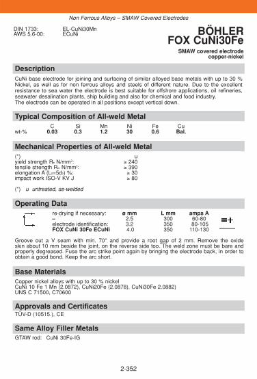
2-352
DescriptionCuNi base electrode for joining and surfacing of similar alloyed base metals with up to 30 %Nickel, as well as for non ferrous alloys and steels of different nature. Due to the excellentresistance to sea water the electrode is best suitable for offshore applications, oil refineries,seawater desalination plants, ship building and also for chemical and food industry.The electrode can be operated in all positions except vertical down.
Approvals and CertificatesTÜV-D (10515.), CE
Base MaterialsCopper nickel alloys with up to 30 % nickelCuNi 10 Fe 1 Mn (2.0872), CuNi20Fe (2.0878), CuNi30Fe 2.0882)UNS C 71500, C70600
Operating Datare-drying if necessary: ø mm L mm amps A– 2.5 300 60-80electrode identification: 3.2 350 80-105FOX CuNi 30Fe ECuNi 4.0 350 110-130
Groove out a V seam with min. 70° and provide a root gap of 2 mm. Remove the oxide skin about 10 mm beside the joint, on the reverse side too. The weld zone must be bare andproperly degreased. Fuse the arc strike point again by bringing the electrode back, in order toobtain a good bond. Keep the arc short.
Mechanical Properties of All-weld Metal(*) uyield strength Re N/mm2: ≥ 240tensile strength Rm N/mm2: ≥ 390elongation A (L0=5d0) %: ≥ 30impact work ISO-V KV J ≥ 80
(*) u untreated, as-welded
Typical Composition of All-weld MetalC Si Mn Ni Fe Cu
wt-% 0.03 0.3 1.2 30 0.6 Bal.
DIN 1733: EL-CuNi30MnAWS 5.6-00: ECuNi BÖHLER
FOX CuNi30FeSMAW covered electrode
copper-nickel
Non Ferrous Alloys – SMAW Covered Electrodes
Same Alloy Filler MetalsGTAW rod: CuNi 30Fe-IG

2-353
DescriptionGTAW rod for joining and surfacing of similar alloyed base metals with up to 30 % Nickel, aswell as for non ferrous alloys and steels of different nature. Due to the excellent resistance tosea water, it is best suitable for offshore applications, oil refineries, seawater desalinationplants, ship building and also for chemical and food industry.
Approvals and CertificatesTÜV-D (10517.), CE
Base MaterialsCopper nickel alloys with up to 30 % nickelCuNi10Fe1Mn (2.0872), CuNi20Fe (2.0878), CuNi30Fe (2.0882)UNS C71500, C70600
Operating Datashielding gas: ø mm100 % Argon 1.6rod marking: 2.0front: 2.0837 2.4back: ERCuNi7Groove out a V seam with min. 70° and provide a root gap of 2 mm. Remove the oxide skin about 10 mm beside the joint, on the reverse side too. The weld zone must be bare and properly degreased.
Mechanical Properties of All-weld Metal(*) uyield strength Re N/mm2: ≥ 200tensile strength Rm N/mm2: ≥ 360elongation A (L0=5d0) %: ≥ 30
HB 120
(*) u untreated, as-welded – shielding gas Argon
Typical Composition of Welding RodC Mn Ni Fe Ti Cu
wt-% < 0.05 0.8 30 0.6 < 0.5 Bal.
EN 14640:2005: S Cu 7158 (CuNi30)AWS A 5.7-04 ERCuNiW.Nr.: 2.0837
BÖHLER CuNi30Fe-IGGTAW rod, CuNi-alloys
Non Ferrous Alloys - GTAW Rods
Same Alloy Filler MetalsSMAW electrode: FOX CuNi 30 Fe
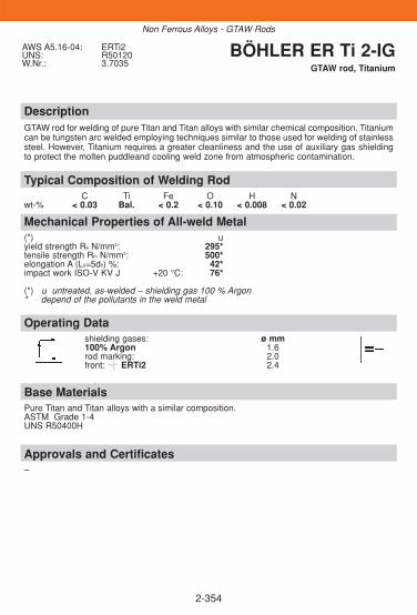
2-354
DescriptionGTAW rod for welding of pure Titan and Titan alloys with similar chemical composition. Titaniumcan be tungsten arc welded employing techniques similar to those used for welding of stainlesssteel. However, Titanium requires a greater cleanliness and the use of auxiliary gas shieldingto protect the molten puddleand cooling weld zone from atmospheric contamination.
Approvals and Certificates–
Base MaterialsPure Titan and Titan alloys with a similar composition.ASTM Grade 1-4UNS R50400H
Operating Datashielding gases: ø mm100% Argon 1.6rod marking: 2.0front: ERTi2 2.4
Mechanical Properties of All-weld Metal(*) uyield strength Re N/mm2: 295*tensile strength Rm N/mm2: 500*elongation A (L0=5d0) %: 42*impact work ISO-V KV J +20 °C: 76*
(*) u untreated, as-welded – shielding gas 100 % Argon* depend of the pollutants in the weld metal
Typical Composition of Welding RodC Ti Fe O H N
wt-% < 0.03 Bal. < 0.2 < 0.10 < 0.008 < 0.02
AWS A5.16-04: ERTi2UNS: R50120W.Nr.: 3.7035
BÖHLER ER Ti 2-IGGTAW rod, Titanium
Non Ferrous Alloys - GTAW Rods

2-355
2.11. Sub-arc Welding Fluxes
ObjectivesThis section contains a brief description of the characteristic features of sub-arc welding fluxes from BÖHLER Welding.Basically the flux has decisive effect on the result of welding operations. Itsinfluence on the melting characteristics and various other physical propertiessuch as viscosity, surface tension, density, thermal expansion, and conduc-tivity in turn has a considerable bearing on the appearance of the bead sur-face and the slag removability.Another major consideration here is the influence which the flux exertsthrough the metallurgical reaction on the chemical composition, and thusalso on the mechanical properties of the deposit.
Contents
OVERVIEW ..............................................................................................356
WELDING FLUXES FOR UNALLOYED AND
LOW-ALLOYED SAW-WIRES..................................................................357
WELDING FLUXES FOR HIGH-ALLOYED STAINLESS STEEL
SAW-WIRES.............................................................................................361
WELDING FLUXES FOR HIGH-ALLOYED CREEP RESISTANT
SAW-WIRES.............................................................................................363
◆
◆
Sub-arc Welding Flux

2-356
◆
◆
Sub-arc Welding Flux
Overview – Standard Classifications
Böhler EN AWSSub-arc Welding FluxBB 24 760: SA FB 1 65 DC H5 –BB 25 760: SA FB 1 68 AC H5 –BB 33 M 760: SA AR 1 97 ACBF 16 760: SF MS 1 78 ACBB 202 760: SA FB 2 DC –BB 203 760: SA FB 2 DC –BB 430 760: SA FB 1 55 AC –BB 444 760: SA FB 2 –BB 910 760: SA FB 2 55 DC –
Overview – Typical Chemical Composition
Böhler SiO2+ CaO+ CaF2 Al2O3+ Al2O3+ FeO K2O+
TiO2 MgO MnO CaO Na2OSAW Welding FluxBB 24 15 37.5 25 19.5 – – 3BB 25 15 29.5 25 23.5 – – –BB 33 M 27 15.5 25 54.5 – – –BF 16 44 (SiO2) 13.5 23 38.5 – 1 –BB 202 10 –1 50 – 38 (Al2O3) – –BB 203 20 26.5 32 18 (Al2O3) – – –BB 430 15 35.5 26 21.5 – – –BB 444 4 (SiO2) 55.5 - 30 (Al2O3) – 9 (F-) 2BB 910 14 32.5 31 18.5 – – –
SAW fluxes are not specifiedaccording to AWS-standards

DescriptionBÖHLER BB 24 is an agglomerated welding flux of the fluoride-basic type. It is characterised by its neutral metallurgical behaviour. When used in combination with suitable wire electrodes the weld metal displays high toughness properties at low/subzero temperatures. The flux is designed for joining and surfa-cing applications on general-purpose structural steels, fine-grained high strength and low temperature steels,and high-temperature steel grades. BÖHLER BB 24 is a hydrogen-controlled welding flux with hydrogen con-tents of maximum 5 ml/100 g weld deposit. BÖHLER BB 24-SC is a special version of flux BÖHLER BB 24.It is especially designed for step-cooling applications and also suitable for A.C. and tandem welding.
Typical Composition of All-weld Metal with different WiresBöhler SAW wires C Si Mn Cr Ni Mo V WBöhler EMS 2 0.07 0.25 1.20Böhler EMS 3 0.08 0.25 1.50Böhler EMS 2 Mo 0.07 0.25 1.15 0.45Böhler EMS 2 CrMo 0.08 0.25 0.95 1.1 0.45Böhler CM 2-UP 0.08 0.25 0.75 2.4 0.95Böhler CM 5-UP 0.06 0.40 0.75 5.5 0.55Böhler 20 MVW-UP 0.16 0.3 0.75 11.4 0.45 0.85 0.30 0.50Böhler 3 NiMo1-UP 0.09 0.25 1.65 0.9 0.55Böhler 3 NiCrMo 2.5-UP 0.06 0.3 1.5 0.5 2.2 0.50Böhler Ni 2-UP 0.07 0.25 1.15 2.2
Approvals and CertificatesDB (51.014.02), ÖBB; Approval is available for BÖHLER BB 24 together with the BÖHLER-wires: TÜV-D: EMS 2, EMS 3, EMS 2 Mo, EMS 2 CrMo, CM 2-UP, 3 NiMo 1-UP, 20 MVW-UP; UDT: EMS 2,EMS 2 Mo, EMS 2 CrMo, CM 2-UP, CM 5-UP, Ni2-UP, 3NiCrMo2,5-UP, 3NiMo1-UP
Base Materialsmild steels, high temperature and creep resistant steels, cryogenic steels, fine-grained steels
Properties and Operating Databasicity acc. Boniczewski: 2.5 weight %bulk density: 1.0 kg/dm3
grain size acc. EN 760: 0.3 - 2.0 mmflux consumption: 1.0 kg flux per kg wirere-drying: 300 – 350 °C, 2 h – 10 h
Composition of Sub-arc Welding FluxSiO2+TiO2 CaO+MgO Al2O3+MnO CaF2 K2O+Na2O
wt-% 15 37 19 25 3
EN 760:1996: SA FB 1 65 DC H5 BÖHLER BB 24BÖHLER BB 24 SC*
SAW flux, fluoride-basic type
2-357
Sub-arc Welding Flux
Designation wire class. classification for wire flux/combinationaccording EN according EN 756 according AWS 5.17 / 5.23
BÖHLER EMS 2 S 2 S 38 4 FB S2 F 7 A 8-EM12K / F 48 A 6-EM12KBÖHLER EMS 3 S 3 S 42 4 FB S3 F 7 A 4-EH10K / F 48 A 4-EH10KBÖHLER 3 NiMo1-UP S Z 3Ni1Mo S 50 4 FB S3Ni1Mo F9A4-EF3(mod)-F3/F62A4-EF3(mod.)-F3BÖHLER 3 NiCrMo 2.5-UP S Z 3Ni2CrMo S 69 6 FB S3Ni2CrMo F11A8-EM4(mod)-M4/F76A6-EM4(mod)-M4BÖHLER Ni 2-UP S 2Ni2 S 46 6 FB S2Ni2 F8A8-ENi2-Ni2 / F55A6-ENi2-Ni2BÖHLER EMS 2 Mo S 2 Mo S 46 4 FB S2Mo F 8 A 4-EA2-A2 / F 55 A 4-EA2-A2BÖHLER EMS 2 CrMo S CrMo1 - F 8 P 4-EB2-B2 / F 55 P 4-EB2-B2BÖHLER CM 2-UP S CrMo2 - F 9 P 2-EB3-B3 / F 55 P 0-EB3-B3BÖHLER CM 5-UP S CrMo5 - F 9 P Z-EB6-B6 / F 62 P Z-EB6-B6BÖHLER 20 MVW-UP S CrMoWV12 - -
*

2-358
DescriptionBÖHLER BB 25 is an agglomerated basic flux suitable for welding of mild and low alloyedsteels with good weld metal impact values at low temperatures. Suitable for single and multi-pass technique.The flux is active and shows some pickup of manganese and silicon. BÖHLER BB 25 is ahydrogen-controlled welding flux with hydrogen contents of maximum 5 ml/100 g weld deposit.
Typical Composition of All-weld Metal with different WiresBöhler SAW-Wires C Si Mn Cr MoBöhler EMS 2 0.07 0.4 1.45Böhler EMS 3 0.06 0.35 1.7Böhler EMS 2 Mo 0.07 0.4 1.5 0.5Böhler EMS 2 CrMo 0.07 0.4 1.35 1.25 0.5
Designation wire class. classification for wire flux/combinationaccording EN according EN 756 according AWS 5.17 / 5.23
BÖHLER EMS 2 S 2 S 42 4 FB S2 F 7 A 4-EM12K / F 48 A 4-EM12KBÖHLER EMS 3 S 3 S 42 3 FB S3 F 7 A 3-EH10K / F 48 A 2-EH10KBÖHLER EMS 2 Mo S 2 Mo S 46 3 FB S2Mo F 8 A 4-EA2-A2 / F 55 A 4-EA2-A2BÖHLER EMS 2 CrMo S CrMo 1 – F 8 P 4-EB2-B2 / F 55 P 4-EB2-B2
Base Materialsmild steels, high temperature steels, fine-grained steels
Properties and Operating Databasicity acc. Boniczewski: 2.2 weight %bulk density: 1.0 kg/dm3
grain size acc. EN 760: 0.2 - 2.0 mmflux consumption: 1.0 kg flux per kg wirere-drying: 300 – 350 °C, 2 h – 10 h
Composition of Sub-arc Welding FluxSiO2+TiO2 CaO+MgO Al2O3+MnO CaF2
wt-% 15 29.5 23.5 25
EN 760:1996: SA FB 1 68 AC H5 BÖHLER BB 25SAW flux, fluoride-basic type
Sub-arc Welding Flux
Approvals and CertificatesApproval is available for BÖHLER BB 25 together with the BÖHLER-wires: TÜV-D: EMS 2 Mo, EMS 2 CrMo; TÜV-A: EMS 2, EMS 2 Mo, EMS 2 CrMo; UDT: EMS 2, EMS 2 Mo,EMS 2 CrMo; ABS: EMS 2 CrMo

DescriptionBÖHLER BB 33 M is an agglomerated welding flux. It is a aluminium-rutile-type suited for high-speed welding of mild and low-alloyed steels.It produces smooth welding beads even at travel speeds higher than 1.5 m/min.
EN 760:1996: SA AR 1 97 AC BÖHLER BB 33 M SAW flux, aluminium-rutile-type
2-359
Typical Composition of All-weld Metal with different WiresBöhler SAW-Wires C Si Mn Mo Böhler EMS 2 0.08 0.7 1.3 –Böhler EMS 3 0.08 0.75 1.7 –Böhler EMS 2 Mo 0.07 0.8 1.5 0.5
Approvals and CertificatesDB (51.014.01), ÖBBApproval is available for BÖHLER BB 33 M together with BÖHLER-wires. TÜV-D: EMS 2,EMS 2 Mo. TÜV-A: EMS 2, EMS 2 Mo. UDT: EMS 2
Base Materialsmild steels and low alloy steels
Properties and Operating Databasicity acc. Boniczewski: 0.6 weight %bulk density: 1.4 kg/dm3
grain size acc. EN 760: 0.2 - 2.0 mmflux consumption: 1.3 kg flux per kg wirere-drying: 275 – 325 °C, 2 h – 4 h
Composition of Sub-arc Welding FluxAl2O3+MnO SiO2+TiO2 CaO+MgO CaF2
wt-% 54 27 5 5
Sub-arc Welding Flux
Designation wire class. classification for wire flux/combinationaccording EN according EN 756 according AWS 5.17 / 5.23
BÖHLER EMS 2 S 2 S 46 0 AR S2 F 7 A Z-EM12K / F 48 A 0-EM12KBÖHLER EMS 3 S 3 S 50 0 AR S3 F 7 A Z-EH10K / F 48 A 0-EH10KBÖHLER EMS 2 Mo S 2 Mo S 46 Z AR S2Mo F 8 A Z-EA2-A2(mod) F 55 A 0-EA2-A2(mod)

DescriptionBÖHLER BF 16 is a fused manganese-silicate welding flux with acid characteristic. It is veryhomogeneous and not susceptible to moisture. The welding flux provides smooth beadstogether with a good slag detachability.Its metallurgical behaviour shows a slight pick up of manganese and silicon.It is suited for joint welds of mild steel constructural work of thinner walled (< 20 mm) compo-nents as well as for hardfacing applications and allows a high current carrying capacity on bothAC and DC.
EN 760:1996: SF MS 1 78 AC BÖHLER BF 16SAW flux, manganese-silicate-type
2-360
Typical Composition of All-weld Metal with different WiresBöhler SAW-Wires C Si Mn Böhler EMS 2 0.04 0.5 1.3Böhler EMS 3 0.04 0.45 1.7
Base Materialsmild steels
Properties and Operating Databasicity acc. Boniczewski: 0.7 weight %bulk density: 1.6 kg/dm3
grain size acc. EN 760: 0.2 - 2.0 mmflux consumption: 1.1 - 1.4 kg flux per kg wirere-drying: 250 – 350 °C, 1 h – 10 h
Composition of Sub-arc Welding FluxSiO2 CaO+MgO Al2O3+MnO CaF2 FeO
wt-% 44 13 38 3 1
Sub-arc Welding Flux
Designation wire class. classification for wire flux/combinationaccording EN according EN 756 according AWS 5.17 / 5.23
BÖHLER EMS 2 S 2 S 38 0 MS S2 F 6 A 0-EM12K / F 43 A 2-EM12KBÖHLER EMS 3 S 3 S 38 0 MS S3 F 6 A 0-EH10K / F 43 A 3-EH10K
Approvals and CertificatesApproval is available for BÖHLER BF 16 together with BÖHLER-wires. TÜV-A: EMS 2, EMS 2 Mo.UDT: EMS 2

DescriptionBÖHLER BB 202 is an agglomerated fluoride-basic flux for single and multipass welding of Cr-steels and non stabilised and stabilised austenitic CrNi(Mo)-steels as well as ferritic-austeniticDuplex-steels. The flux BB 202 produces well contoured and smooth welding beads, easy slagremoval without any slag residues and good welding characteristics even for fillet welds arevery much appreciated by users. It offers an especially low flux consumption.The weld deposits show high purity and good mechanical properties.
EN 760:1996: SA FB 2 DC*DIN 32522: B FB 6 64355 DC 8* ersetzt durch EN 760
BÖHLER BB 202SAW flux, fluoride-basic type
2-361
Typical Composition of All-weld Metal with different WiresBöhler SAW-Wires C Si Mn Cr Ni Mo Nb Cu NBöhler CN 18/11-UP 0.04 0.59 1.3 18.5 19.3Böhler EAS 2-UP 0.02 0.55 1.3 19.5 19.8Böhler SAS 2-UP 0.048 0.60 1.3 19.0 19.5 0.55Böhler EAS 4 M-UP 0.02 0.60 1.2 18.0 12.2 2.8Böhler SAS 4-UP 0.030 0.60 1.2 18.0 11.4 2.8 0.55Böhler ASN 5 SY-UP ≤0.03 0.60 1.2 18.5 13.4 3.5Böhler CN 22/9 N-UP 0.013 0.50 1.1 22.5 18.8 3.2 0.14Böhler CN 23/12-UP 0.015 0.60 1.3 23.5 13.2
Base MaterialsCr-steels and unstabilised or stabilised austenitic CrNi(Mo)-steels as well as austenitic-ferriticduplex steels.
Properties and Operating Databasicity acc. Boniczewski: 2.3 weight %bulk density: 1.0 kg/dm3
grain size acc. EN 760: 2 - 12 (0.2 - 1.2 mm)flux consumption: 0.7 kg flux per kg wirere-drying: 300 – 350 °C, 2 h – 10 h
Composition of Sub-arc Welding FluxSiO2+TiO2 Al2O3 CaF2
wt-% 10 38 50
Sub-arc Welding Flux
Designation class. for wire classification for wire flux/combinationacc. EN 12072 according EN according AWS 5.9
BÖHLER CN 18/11-UP S 19 9 H - (ER19-10H)BÖHLER EAS 2-UP S 19 9 L - (ER308L)BÖHLER SAS 2-UP S 19 9 Nb - (ER347)BÖHLER EAS 4 M-UP S 19 12 3 L - (ER316L)BÖHLER SAS 4-UP S 19 12 3 Nb - (ER318)BÖHLER ASN 5 SY-UP - - (ER317L)BÖHLER CN 22/9 N-UP S 22 9 3 NL - (ER2209)BÖHLER CN 23/12-UP S 23 12 L - (ER309L)
Approvals and CertificatesApproval is available for BÖHLER BB 202 together with the following BÖHLER-wires: TÜV-D:EAS 2-UP, EAS 4 M-UP, SAS 2-UP, SAS 4-UP, CN 22/9 N-UP; TÜV-A: SAS 2-UP, SAS 4-UP, CN 20/25M-UP, CN 22/9 N-UP; ABS: CN 22/9 N-UP; GL: CN 22/9 N-UP; CL: CN 22/9 N-UP; LR: CN 22/9 N-UP;DNV: CN 22/9 N-UP, CN 23/12-UP; UDT: CN 18/11-UP, EAS 2-UP, EAS 4 M-UP, SAS 2-UP, SAS 4-UP,CN 22/9 N-UP, CN 23/12-UP
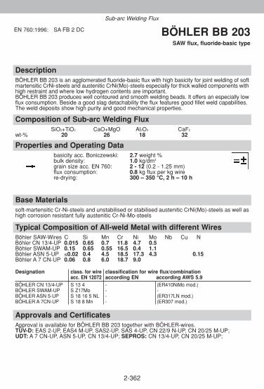
DescriptionBÖHLER BB 203 is an agglomerated fluoride-basic flux with high basicity for joint welding of softmartensitic CrNi-steels and austenitic CrNi(Mo)-steels especially for thick walled components withhigh restraint and where low hydrogen contents are important.BÖHLER BB 203 produces well contoured and smooth welding beads. It offers an especially lowflux consumption. Beside a good slag detachability the flux features good fillet weld capabilities.The weld deposits show high purity and good mechanical properties.
EN 760:1996: SA FB 2 DC BÖHLER BB 203SAW flux, fluoride-basic type
2-362
Typical Composition of All-weld Metal with different WiresBöhler SAW-Wires C Si Mn Cr Ni Mo Nb Cu NBöhler CN 13/4-UP 0.015 0.65 0.7 11.8 4.7 0.5Böhler SWAM-UP 0.15 0.65 0.55 16.5 0.4 1.1Böhler ASN 5-UP ≤0.02 0.4 4.5 18.5 17.3 4.3 0.15Böhler A 7 CN-UP 0.06 0.8 6.0 18.7 9.0
Base Materialssoft-martensitic Cr-Ni-steels and unstabilised or stabilised austenitic CrNi(Mo)-steels as well ashigh corrosion resistant fully austenitic Cr-Ni-Mo-steels
Properties and Operating Databasicity acc. Boniczewski: 2.7 weight %bulk density: 1.0 kg/dm3
grain size acc. EN 760: 2 - 12 (0.2 - 1.25 mm)flux consumption: 0.8 kg flux per kg wirere-drying: 300 – 350 °C, 2 h – 10 h
Composition of Sub-arc Welding FluxSiO2+TiO2 CaO+MgO Al2O3 CaF2
wt-% 20 26 18 32
Sub-arc Welding Flux
Designation class. for wire classification for wire flux/combinationacc. EN 12072 according EN according AWS 5.9
BÖHLER CN 13/4-UP S 13 4 - (ER410NiMo mod.)BÖHLER SWAM-UP S Z17Mo - -BÖHLER ASN 5-UP S 18 16 5 NL - (ER317LN mod.)BÖHLER A 7CN-UP S 18 8 Mn - (ER307 mod.)
Approvals and CertificatesApproval is available for BÖHLER BB 203 together with BÖHLER-wires. TÜV-D: EAS 2-UP, EAS4 M-UP, SAS2-UP, SAS 4-UP, CN 22/9 N-UP, CN 20/25 M-UP; UDT: A 7 CN-UP, ASN 5-UP, CN 13/4-UP; SEPROS: CN 13/4-UP, CN 20/25 M-UP;
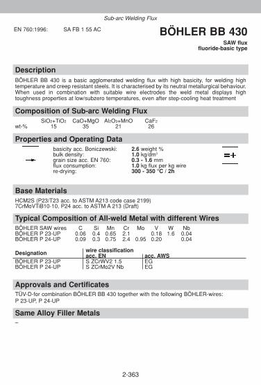
2-363
DescriptionBÖHLER BB 430 is a basic agglomerated welding flux with high basicity, for welding high temperature and creep resistant steels. It is characterised by its neutral metallurgical behaviour.When used in combination with suitable wire electrodes the weld metal displays high toughness properties at low/subzero temperatures, even after step-cooling heat treatment
Approvals and CertificatesTÜV-D-for combination BÖHLER BB 430 together with the following BÖHLER-wires:P 23-UP, P 24-UP
Same Alloy Filler Metals–
Base MaterialsHCM2S (P23/T23 acc. to ASTM A213 code case 2199)7CrMoVTiB10-10, P24 acc. to ASTM A 213 (Draft)
Properties and Operating Databasicity acc. Boniczewski: 2.6 weight %bulk density: 1.0 kg/dm3
grain size acc. EN 760: 0.3 - 1.6 mmflux consumption: 1.0 kg flux per kg wirere-drying: 300 - 350 °C / 2h
Composition of Sub-arc Welding FluxSiO2+TiO2 CaO+MgO Al2O3+MnO CaF2
wt-% 15 35 21 26
Typical Composition of All-weld Metal with different WiresBÖHLER SAW wires C Si Mn Cr Mo V W Nb BÖHLER P 23-UP 0.06 0.4 0.65 2.1 0.18 1.6 0.04 BÖHLER P 24-UP 0.09 0.3 0.75 2.4 0.95 0.20 0.04
Designation wire classificationacc. EN acc. AWS
BÖHLER P 23-UP S ZCrWV2 1.5 EGBÖHLER P 24-UP S ZCrMo2V Nb EG
EN 760:1996: SA FB 1 55 AC BÖHLER BB 430SAW flux
fluoride-basic type
Sub-arc Welding Flux

2-364
DescriptionBÖHLER BB 444 is a highly basic agglomerated welding flux, designed for welding and cladding of NiCr(Mo) alloys. Highly resistant against hot cracking thanks to its low level of Si pick up.
Approvals and CertificatesTÜV-D-for combination BÖHLER BB 444 together with the following BÖHLER-wires:NIBAS 70/20-UP, NIBAS 625-UP
Same Alloy Filler Metals–
Base Materialsnickel and nickel alloys
Properties and Operating Databasicity acc. Boniczewski: 5.1 weight %bulk density: 1.0 kg/dm3
grain size acc. EN 760: 0.4 -1.4 mmflux consumption: 1.0 kg flux per kg wirere-drying: 300 - 400 °C / 1h - 2h
Typical Analysis of Sub-arc Welding FluxSiO2 CaO+MgO Al2O3 K2O+Na2O F-
wt-% 4 55 30 2 9
Typical Composition of All-weld Metal with different wiresBÖHLER SAW wires C Si Mn Cr Mo Ni Nb Ti W Co FeBÖHLER NIBAS 70/20-UP 0.02 0.25 3.0 20.0 Rest 2.4 + <1.0BÖHLER NIBAS 625-UP 0.02 0.25 0.2 21.5 8.5 Rest 3.2 <1.0BÖHLER NIBAS C 24-UP 0.015 0.2 <0.5 22.5 15.8 Rest <1.0BÖHLER NIBAS 617-UP <0.06 <0.4 <0.3 21.2 8.9 Rest + Al 1.1 10.0 <1.0BÖHLER NIBAS C 276-UP <0.012 0.15 0.5 15.5 16.0 Rest + 3.3 <7.0
Designation wire classificationacc. EN acc. AWS
BÖHLER NIBAS 70/20-UP SNi 6082 (NiCr20Mn3Nb) ERNiCr-3BÖHLER NIBAS 625UP SNi 6625 (NiCr22Mo9Nb) ERNiCrMo-3BÖHLER NIBAS C 24-UP SNi 6059 (NiCr23Mo16) ERNiCrMo-13BÖHLER NIBAS 617-UP S Ni 6617 (NiCr22Co12 Mo) ERNiCrCoMo-1BÖHLER NIBAS C 276-UP SNi 6276 (NiCr15Mo16Fe6W4) ERNiCrMo-4
EN 760:1996: SA FB 2 BÖHLER BB 444SAW flux
fluoride-basic type
Sub-arc Welding Flux

DescriptionBÖHLER BB 910 is an agglomerated fluoride-basic special welding flux with high basicity formultipass welding of creep resistant 9 % Cr-steels like P91/T91/P92/T92 and NF 616. Themetallurgical behaviour concerning Si and Mn is neutral. The flux BB 910 produces well contoured and smooth welding beads with good slag release aswell as appropriate weld metal ductility and impact behaviour after tempering.BÖHLER BB 910 is a hydrogen-controlled welding flux with hydrogen contents of maximum 5 ml/100 g weld deposit.
EN 760:1996: SA FB 2 55 DC 8 BÖHLER BB 910SAW flux, fluoride-basic type
2-365
Typical Composition of All-weld Metal with different WiresBöhler SAW-Wires C Si Mn Cr Ni Mo V Nb T NBöhler C 9 MV-UP 0.11 0.3 0.7 8.9 0.6 0.9 0.2 0.05Böhler P 92-UP 0.1 0.4 0.6 8.7 0.6 0.45 0.2 0.05 1.65Böhler 20 MVW-UP 0.18 0.25 0.7 11.2 0.5 0.85 0.24 1.5
Base Materialshigh creep resistant 9 %Cr-steels like grade P91/T91, and NF616
Properties and Operating Databasicity acc. Boniczewski: 2.9 weight %bulk density: 1.0 kg/dm3
grain size acc. EN 760: 0.3 - 2.0 mmflux consumption: 1.0 kg flux per kg wirere-drying: 300 – 350 °C, 2 h – 10 h
Composition of Sub-arc Welding FluxSiO2+TiO2 CaO+MgO Al2O3+MnO CaF2
wt-% 14 32 18 31
Sub-arc Welding Flux
Designation class. for wire classification for wire flux/combinationacc. EN 12070 according EN according AWS 5.23
BÖHLER C 9 MV-UP S CrMo91 - F 9 P Z-EB9-B9 / F 62 P Z-EB9-B9BÖHLER P 92-UP S Z CrMo92 - -BÖHLER 20 MVW-UP S CrMoWV12 - -
Approvals and CertificatesApproval is available for BÖHLER BB 910 together with the BÖHLER-wires:ÜV-D: C 9 MV-UP, P 92-UP; CL: C9MV-UP; UDT: C9 MV-UP, P92-UP; SEPROS: C9MV-UP

Notes
2-366

Notes
2-367

Notes
2-368

3-1
3. Selection Guide
ÜbersichtInformation über Werkstoffe zählt zu den wesentlichen Voraussetzungen füreine zielführende Auswahl von Schweißzusätzen. Der beschränkte Umfangdieses Handbuches erlaubt zwar nicht eine vollständige Angabe aller rele-vanten Eigenschaften, doch soll zumindest ein Überblick über die gültigenEN- und die auslaufenden bzw. noch gültigen DIN-Bezeichnungen und diechemische Zusammensetzung aller im europäischen Raum mit Werkstoff-nummern genormten Werkstoffe gegeben werden
Contents
3.1 WELDING CONSUMABLES
FOR THE OFFSHORE INDUSTRY . . . . . . . . . . . . . . . . . . . . . . . . . . .2
WELDING CONSUMABLES
FOR THE CHEMICAL AND PETROCHEMICAL INDUSTRY . . . . . . . .4
WELDING CONSUMABLES
FOR THERMAL POWER PLANTS . . . . . . . . . . . . . . . . . . . . . . . . . . . .8
DISSIMILAR WELDS WITH
HIGH TEMPERATURE STEELS . . . . . . . . . . . . . . . . . . . . . . . . . . . . .10
WELDING CONSUMABLES
FOR HYDRO POWER . . . . . . . . . . . . . . . . . . . . . . . . . . . . . . . . . . . .12
3.2 SELECTION TABLES
BASE MATERIAL ORIENTED SELECTION . . . . . . . . . . . . . . . . . . . .13
3.3 PROCESS-BASED SELECTION OF CONSUMABLES . . . . . . . . . . .33
3.4 MATERIAL-BASED SELECTION OF CONSUMABLES . . . . . . . . . . .45
3.5 WELDING TECHNOLOGY DETAILS . . . . . . . . . . . . . . . . . . . . . . . . .87
Selection Guide
◆

3-2
Wel
din
g p
roce
sses
FOX
CN
13/
4FO
X C
N 1
3/4
Supr
aC
N 1
3/4-
IGC
N 1
3/4-
MC
C
N 1
3/4-
IG
Au
sten
itic
316L 310
S316
00
S310
00
FOX
EA
S 4
M-A
FOX
EA
S 4
M
FOX
FFB
-AFO
X F
FB
EAS
4M-I
G
FFB-
IG
EAS
4 PW
-FD
EAS
4M-F
DEA
S 4M
-IG
(Si
)
FFB-
IG
EAS
4M-U
P +
BB
202
Mild
ste
els
Re
< 3
80 M
PaA
106G
r.B
FOX
EV
50
EML
5H
L 51
-FD
EMS
2 +
BB
400
AP
I P
ipe
stee
lsA
PI 5
L-X
52
API
X56
-X65
API
X60
-X65
API
X70
FOX
EV
PIP
EFO
X B
VD
85
FOX
BV
D 8
5FO
X B
VD
90
MFO
X E
V 6
0 PI
PEFO
X B
VD
85
FOX
EV
70
PIPE
FOX
BV
D 9
0
EML
5
I 52
Ni
I 52
Ni
Ti 5
2-FD
Ti 6
0-FD
SG 3
-P
SG 3
-P(m
ax. X
60)
K-N
ova
Ni
K-N
ova
Ni
K-N
ova
Ni
EMS
2 +
BB
400
EMS
2 +
BB
400
Hig
h st
reng
th s
teel
sR
e >
380
MPa
S420
-S46
0
S500
AIS
I 413
0
S690
Q
FOX
EV
60
FOX
EV
65
FOX
EV
75
FOX
EV
85
EML
5
I 52
Ni
I 52
Ni
(Roo
t pa
ss o
nly)
Ti 6
0-FD
K-N
ova
Ni
K-N
ova
Ni
NiM
o 1-
IG
NiC
rMo2
.5-I
G
3NiM
o1-U
P +
BB
420
TT
R3N
iMo1
-UP
+
BB 4
20T
TR
3NiM
o1-U
P +
BB
420
TT
R3
NiC
rMo2
.5-U
P +
BB
420T
TR,B
B42
0TTR
C
Sta
inle
ss s
teel
sM
arte
nsi
tic
13C
r 4N
i
Bas
e m
etal
UN
S/A
STM
AIS
I/API
SMA
WFC
AW
GT
AW
GM
AW
SAW
3.1 SELECTION GUIDE FOR THE OFFSHORE INDUSTRY
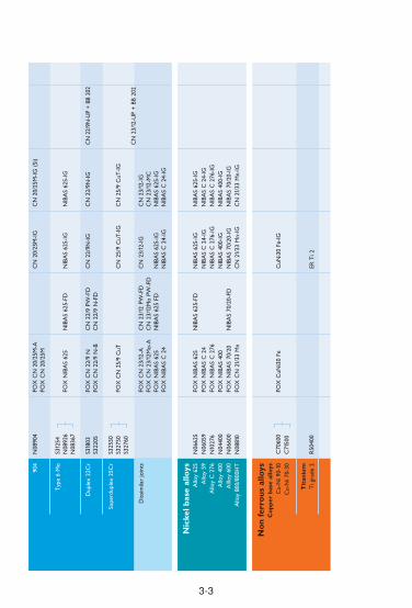
3-3
Nic
kel b
ase
allo
ysA
lloy
625
Allo
y 59
Allo
y C
276
Allo
y 40
0A
llloy
600
Allo
y 80
0/80
0HT
N06
625
N06
059
N10
276
N04
400
N06
600
N08
810
FOX
NIB
AS
625
FOX
NIB
AS
C 2
4FO
X N
IBA
S C
276
FOX
NIB
AS
400
FOX
NIB
AS
70/2
0FO
X C
N 2
1/33
Mn
NIB
AS
625-
IGN
IBA
S C
24-
IGN
IBA
S C
276
-IG
NIB
AS
400-
IGN
IBA
S 70
/20-
IGC
N 2
1/33
Mn-
IG
NIB
AS
625-
FD
NIB
AS
70/2
0-FD
NIB
AS
625-
IGN
IBA
S C
24-
IGN
IBA
S C
276
-IG
NIB
AS
400-
IGN
IBA
S 70
/20-
IGC
N 2
1/33
Mn-
IG
904
Typ
e 6
Mo
Dup
lex
22C
r
Supe
rdup
lex
25C
r
Dis
sim
ilar
join
ts
N08
904
S312
54N
0892
6N
0836
7
S318
03S3
2205
S325
50S3
2750
S327
60
FOX
CN
20/
25M
-AFO
X C
N 2
0/25
M
FOX
NIB
AS
625
FOX
CN
22/
9 N
FOX
CN
22/
9 N
-B
FOX
CN
25/
9 C
uT
FOX
CN
23/
12-A
FOX
CN
23/
12M
o-A
FOX
NIB
AS
625
FOX
NIB
AS
C 2
4
CN
20/
25M
-IG
NIB
AS
625-
IG
CN
22/
9N-I
G
CN
25/
9 C
uT-I
G
CN
23/
12-I
G
NIB
AS
625-
IGN
IBA
S C
24-
IG
NIB
AS
625-
FD
CN
22/
9 PW
-FD
CN
22/
9 N
-FD
CN
23/
12 P
W-F
DC
N 2
3/12
Mo
PW-F
DN
IBA
S 62
5 FD
CN
20/
25M
-IG
(Si
)
NIB
AS
625-
IG
CN
22/
9N-I
G
CN
25/
9 C
uT-I
G
CN
23/
12-I
GC
N 2
3/12
-MC
NIB
AS
625-
IGN
IBA
S C
24-
IG
CN
22/
9N-U
P +
BB 2
02
CN
23/
12-U
P +
BB
202
No
n f
erro
us
allo
ysC
op
per
bas
e al
loys
Cu-
Ni 9
0-10
Cu-
Ni 7
0-30
Tit
aniu
mT
i gra
de 2
C70
600
C71
500
R50
400
FOX
CuN
i30
FeC
uNi3
0 Fe
-IG
ER T
i 2

3-4
Hig
h t
emp
erat
ure
an
dcr
eep
res
ista
nt
stee
ls
0,5M
o1C
r 0,
5Mo
0,5C
r 1M
o +
V21
/ 4C
r 1M
o21
/ 4C
r 1M
o (m
od.)
5Cr
0,5M
o9C
r 1M
o9C
r 1M
o +
V(W
)
12C
r 1M
o +
VW
18C
r 11
Ni
18C
r 10
Ni +
Nb
P/T
1P/
T11
– P/T
22P/
T23
P/T
24P/
T5
P/T
9P/
T91
P/T
911
P/T
92– 30
4H32
1H
347H
FOX
DM
O T
i, K
bFO
X D
CM
S T
i, K
bFO
X D
MV
83K
bFO
X C
M 2
Kb
FOX
P 2
3FO
X P
24
FOX
CM
5 K
bFO
X C
M 9
Kb
FOX
C 9
MV
FOX
C 9
MV
WFO
X P
92
FOX
20
MV
WFO
X C
N 1
8/11
FOX
E 3
08 H
FOX
E 3
47 H
E 30
8 H
-FD
E 30
8 H
PW
-FD
DM
O-I
GD
CM
S-IG
DM
V 8
3-IG
CM
2-I
GP
23-I
GP
24-I
GC
M 5
-IG
CM
9-I
GC
9 M
V-I
G
C 9
MV
W-I
GP
92-I
G20
MV
W-I
GC
N 1
8/11
-IG
ER 3
08 H
-IG
DM
O-I
GD
CM
S-IG
DM
V 8
3-IG
CM
2-I
G
CM
5-I
G
C 9
MV
-IG
C 9
MV
-MC
CN
18/
11-I
G
EMS
2Mo+
BB 2
4EM
S 2C
rMo+
BB 2
4
CM
2-U
P+BB
24
P 23
-UP+
BB 4
30P
24-U
P+BB
430
CM
5-U
P+BB
24
C 9
MV
-UP+
BB 9
10
P 92
-UP+
BB 9
1020
MV
W-U
P+BB
24
CN
18/
11-U
P+BB
202
Sta
inle
ss s
teel
sA
ust
enit
ic
19C
r 9N
i L
19C
r 9N
i 3M
o L
19C
r 13
Ni 4
Mo
L
18C
r 16
Ni 5
Mo
NL
304L
316L
317L
317L
N
FOX
EA
S 2
FOX
EA
S 2-
AFO
X E
AS
2-V
DFO
X E
AS
4 M
FOX
EA
S 4
M-A
FOX
EA
S 4
M-V
DFO
X E
AS
4 M
-TS
FOX
E 3
17L
FOX
ASN
5FO
X A
SN 5
-A
EAS
2-FD
EAS
2 PW
-FD
EAS
4 M
-FD
EAS
4 PW
-FD
E 31
7L-F
DE
317L
PW
-FD
EAS
2-IG
EAS
4 M
-IG
ASN
5-I
G
EAS
2-IG
(Si
)EA
S 2
MC
EAS
4 M
-IG
(Si
)EA
S 4
M-M
C
ASN
5-I
G (
Si)
EAS
2-U
P+BB
202
EAS
4 M
-UP+
BB 2
02
ASN
5 S
Y-U
P+BB
202
ASN
5-U
P+BB
203
Wel
din
g p
roce
sses
Bas
e m
etal
sA
ISI/U
NS/
AST
MSM
AW
FCA
WG
TA
WG
MA
WSA
W
3.1 SELECTION GUIDE FOR THE CHEMICAL AND PETROCHEMICAL INDUSTRY

3-5
22C
r 18
Ni 4
Mo
L19
Cr
12N
i 3M
o N
b
19C
r 9N
i Nb
20C
r 25
Ni 5
Mo
CuN
L
Fer
riti
c /
Mar
ten
siti
c13
Cr
NbL
13C
r17
Cr
17C
r M
o18
Cr
NbL
So
ft m
arte
nsi
tic
13C
r 4N
i
16C
r 6N
i Mo
Pre
cip
itat
ion
har
den
ing
17C
r 4N
i Cu
Du
ple
x /
Su
per
du
ple
x
22C
r
25C
r
– 316T
i
347
904L
409
410
431
– 430C
b
CA
6NM
S415
00– – S3
1803
S327
50
FOX
AM
400
FOX
SA
S 4
FOX
SA
S 4-
AFO
X S
AS
2FO
X S
AS
2-A
FOX
CN
20/
25 M
FOX
CN
20/
25 M
-A
FOX
KW
10
FOX
SK
WA
FOX
SK
WA
M
FOX
CN
13/
4 SU
PRA
FOX
CN
13/
4FO
X C
N 1
6/6
M-H
D
FOX
CN
17/
4 PH
FOX
CN
22/
9 N
-BFO
X C
N 2
2/9
NFO
X C
N 2
5/9
CuT
SAS
4-FD
SAS
4 PW
-FD
SAS
2-FD
SAS
2 PW
-FD
CN
22/
9 N
-FD
CN
22/
9 PW
-FD
AM
400
-IG
SAS
4-IG
SAS
2-IG
CN
20/
25 M
-IG
CN
13/
4-IG
CN
22/
9 N
-IG
CN
25/
9 C
uT-I
G
AM
400
-IG
SAS
4-IG
(Si
)
SAS
2-IG
(Si
)
CN
20/
25 M
-IG
(Si
)
KW
5 N
b-IG
KW
10-
IGSK
WA
-IG
, KW
A-I
GSK
WA
M-I
GC
AT
430
L C
b-IG
CN
13/
4-M
CC
N 1
3/4-
IG
CN
22/
9 N
-IG
CN
25/
9 C
uT-I
G
SAS
4-U
P+BB
202
SAS
2-U
P+BB
202
SKW
AM
-UP+
BB 2
03
CN
13/
4-U
P+BB
203
CN
22/
9N-U
P+BB
202

3-6
Sp
ecia
lap
plic
atio
ns
18C
r 8N
i Mn
20C
r 10
Ni 3
Mo
23C
r 12
Ni L
23C
r 12
Ni 2
Mo
L
24C
r 13
Ni L
24C
r 13
Ni N
bL29
Cr
9Ni
19C
r 14
Ni S
i25
Cr
22N
i 2M
o N
L
Dis
sim
ilar
join
ts,
corr
osio
n re
sist
ant
surf
acin
gs
Buffe
r la
yers
Prob
lem
ste
els
Aga
inst
nitr
ic a
cid
URE
A p
lant
eng
inee
ring
FOX
A 7
FOX
A 7
-AFO
X C
N 1
9/9
MFO
X C
N 2
3/12
-A
FOX
CN
23/
12 M
o-A
FOX
CN
24/
13FO
X C
N 2
4/13
Nb
FOX
CN
29/
9FO
X C
N 2
9/9-
AFO
X E
AS
2 Si
FOX
EA
SN 2
5 M
A 7
-FD
A 7
PW
-FD
CN
23/
12-F
DC
N 2
3/12
PW
-FD
CN
23/
12 M
o-FD
CN
23/
12 M
o PW
-FD
A 7
CN
-IG
CN
19/
9 M
-IG
CN
23/
12-I
G
EASN
2 S
i-IG
EASN
25
M-I
G
A 7
-IG
A 7
-MC
CN
19/
9 M
-IG
CN
23/
12-I
GC
N 2
3/12
-MC
A 7
CN
-UP+
BB 2
03
CN
23/
12-U
P+BB
202
Hea
t re
sist
ant
25C
r 4N
i22
Cr
12N
i
25C
r 20
Ni
21C
r 33
Ni M
n
327
309
310
N08
810
/ 80
0H
FOX
FA
FOX
FF
FOX
FF-
AFO
X F
FBFO
X F
FB-A
FOX
CN
21/
33 M
n
FA-I
GFF
-IG
FFB-
IG
CN
21/
33 M
n-IG
FA-I
GFF
-IG
FFB-
IG
CN
21/
33 M
n-IG
A63
3 G
r. E
304L
K81
340
FOX
2.5
Ni
FOX
EA
S 2
FOX
NIB
AS
60/1
5
EAS
2-FD
EAS
2 PW
-FD
EAS
2 PW
-FD
(LF
)N
IBA
S 62
5-FD
2.5
Ni-I
GEA
S 2-
IG
NIB
AS
625-
IG
2.5
Ni-I
GEA
S 2-
IG (
Si)
NIB
AS
625-
IG
Ni 2
-UP+
BB 2
4EA
S 2-
UP+
BB 2
02
NIB
AS
625-
UP+
BB 4
44
Lo
w t
emp
erat
ure
2.5N
i19
Cr
9Ni L 9N
i
Wel
din
g p
roce
sses
Bas
e m
etal
sA
ISI/U
NS/
AST
MSM
AW
FCA
WG
TA
WG
MA
WSA
W
3.1 SELECTION GUIDE FOR THE CHEMICAL AND PETROCHEMICAL INDUSTRY

3-7
25C
r 35
Ni N
b35
Cr
45N
i Nb
– –FO
X C
N 2
5/35
Nb
FOX
CN
35/
45 N
bC
N 2
5/35
Nb-
IGC
N 3
5/45
Nb-
IGC
N 2
5/35
Nb-
IGC
N 3
5/45
Nb-
IG
Nic
kel b
ase
allo
ys
Allo
y 60
0A
lloy
600
Allo
y 62
5A
lloy
C 2
76A
lloy
59A
lloy
400
Allo
y 61
7
N06
600
N06
600
N06
625
N10
276
N06
059
N04
400
N06
617
FOX
NIB
AS
70/1
5FO
X N
IBA
S 70
/20
FOX
NIB
AS
625
FOX
NIB
AS
C 2
76FO
X N
IBA
S C
24
FOX
NIB
AS
400
FOX
NIB
AS
617
NIB
AS
70/2
0-FD
NIB
AS
625-
FDN
IBA
S 70
/20-
IGN
IBA
S 62
5-IG
NIB
AS
C 2
76-I
GN
IBA
S C
24-
IGN
IBA
S 40
0-IG
NIB
AS
617-
IG
NIB
AS
70/2
0-IG
NIB
AS
625-
IGN
IBA
S C
276
-IG
NIB
AS
C 2
4-IG
NIB
AS
400-
IGN
IBA
S 61
7-IG
NIB
AS
70/2
0-U
P+BB
444
NIB
AS
625-
UP+
BB 4
44N
IBA
S C
276
-UP+
BB 4
44N
IBA
S C
24-
UP+
BB 4
44
NIB
AS
617-
UP+
BB 4
44
No
n-f
erro
us
allo
ys
Cu-
Ni 9
0-10
Cu-
Ni 9
0-30
Ti g
rade
2
C70
600
C71
500
R50
400
FOX
CuN
i30
FeFO
X C
uNi3
0 Fe
CuN
i30
Fe-I
GC
uNi3
0 Fe
-IG
ER T
i 2-I
G

3-8
Mild
ste
els
Re
≤ 38
0 M
PaSA
106A
+B
FOX
EV
50
Ti 5
2-FD
EMK
6EM
K 6
EMS
2+BB
24
Hig
h s
tren
gth
ste
els
Re
≤ 50
0 M
PaSA
508
Cl.2
FOX
EV
65
NiM
o 1-
IG3
NiM
o 1-
UP+
BB 2
4
FOX
DM
O T
i, K
bFO
X D
CM
S T
i, K
bFO
X D
CM
VFO
X D
MV
83K
bFO
X C
M 2
Kb
FOX
P 2
3FO
X P
24
FOX
CM
5K
bFO
X C
M 9
Kb
FOX
C 9
MV
FOX
C 9
MV
WFO
X P
92
FOX
20
MV
WFO
X C
N 1
8/11
FOX
E 3
08 H
FOX
E 3
47 H
(DM
O)
(DC
MS)
E 30
8 H
-FD
E 30
8 H
PW
-FD
DM
O-I
GD
CM
S-IG
DM
V 8
3-IG
CM
2-I
GP
23-I
GP
24-I
GC
M 5
-IG
C M
9-I
GC
9 M
V-I
G
C 9
MV
W-I
GP
92-I
G20
MV
W-I
GC
N 1
8/11
-IG
ER 3
08 H
-IG
DM
O-I
GD
CM
S-IG
DM
V 8
3-IG
CM
2-I
G
CM
5-I
G
C 9
MV
-IG
C 9
MV
-MC
CN
18/
11-I
G
EMS
2Mo+
BB 2
4EM
S 2
CrM
o+BB
24
CM
2-U
P+BB
24
P 23
-UP+
BB 4
30P
24-U
P+BB
430
CM
5-U
P+BB
24
C 9
MV
-UP+
BB 9
10
P 92
-UP+
BB 9
1020
MV
W-U
P+BB
24
CN
18/
11-U
P+BB
202
Hig
h T
emp
erat
ure
an
dcr
eep
res
ista
nt
stee
ls
0,5M
o1C
r 0,
5Mo
1.25C
r 1M
o+V
0,5C
r 1M
o +
V2.
25C
r 1M
o2.
25C
r 1M
o (m
od.)
5Cr
0,5M
o9C
r 1M
o9C
r 1M
o +
V(W
)
12C
r 1M
o +
VW
18C
r 11
Ni
18C
r 10
Ni +
Nb
P/T
1P/
T11
– – P/T
22P/
T23
P/T
24P/
T5
P/T
9P/
T91
– P/T
92– 30
4H
347H
Wel
din
g p
roce
sses
Bas
e m
etal
sA
ISI/U
NS/
AST
MSM
AW
FCA
WG
TA
WG
MA
WSA
W
3.1 SELECTION GUIDE FOR THERMAL POWER PLANTS

3-9
Sp
ecia
l ap
plic
atio
ns
18C
r 8N
i Mn
diss
imila
r jo
ints
, re
pair
and
m
aint
enan
ce
FOX
A 7
FOX
A 7
-AA
7-F
DA
7 P
W-F
DA
7 C
N-I
GA
7-I
GA
7-M
CA
7 C
N-U
P+BB
203
Hea
t re
sist
ant
25C
r 4N
i22
Cr
12N
i
25C
r 20
Ni
21C
r 33
Ni M
n
327
309
310
N08
810/
800H
FOX
FA
FOX
FF
FOX
FF-
AFO
X F
FBFO
X F
FB-A
FOX
CN
21/
33 M
n
FA-I
GFF
-IG
FFB-
IG
CN
21/
33 M
n-IG
FA-I
GFF
-IG
FFB-
IG
CN
21/
33 M
n-IG
Nic
kel b
ase
allo
ys
Allo
y 80
0A
lloy
600
Allo
y 62
5A
lloy
617
N06
600
N06
600
N06
625
N06
617
FOX
NIB
AS
70/1
5FO
X N
IBA
S 70
/20
FOX
NIB
AS
625
FOX
NIB
AS
617
NIB
AS
70/2
0-FD
NIB
AS
625-
FDN
IBA
S 70
/20-
IGN
IBA
S 62
5-IG
NIB
AS
617-
IG
NIB
AS
70/2
0-IG
NIB
AS
625-
IGN
IBA
S 61
7-IG
NIB
AS
70/2
0-U
P+BB
444
NIB
AS
625-
UP+
BB 4
44N
IBA
S 61
7-U
P+BB
444

3-10
3.1 DISSIMILAR WELDS WITH HIGH TEMPERATURE STEELS
P/T
1
16M
o3
P/T
11
13C
rMo4
-5
P/T
22
10C
rMo9
-10
P/T
5
X12
CrM
o5
P/T
9
X12
CrM
o9-1
P/T
91
X10
CrM
oVN
b9-1
P/T
92
–
P/T
23
–
P/T
24
7CrM
oVT
iB10
-10
304H
X6C
rNi18
-11
321H
X12
CrN
iTi
18-1
0
347H
X12
CrN
iNb
18-1
0
FOX
D
MO
Kb
FOX
D
MO
Kb
FOX
D
CM
S K
bFO
X
CM
2 K
bFO
X
CM
2 K
bFO
X
CM
2 K
bFO
X
DC
MS
Kb
FOX
D
CM
S K
b
FOX
N
IBA
S 70
/20
FOX
N
IBA
S 70
/15
FOX
N
IBA
S 70
/20
FOX
N
IBA
S 70
/15
FOX
N
IBA
S 70
/20
FOX
N
IBA
S 70
/15
FOX
D
CM
S K
bFO
X
CM
2 K
bFO
X
CM
2 K
bFO
X
CM
2 K
bFO
X
CM
2 K
bFO
X
DC
MS
Kb
FOX
D
CM
S K
b
FOX
N
IBA
S 70
/20
FOX
N
IBA
S 70
/15
FOX
N
IBA
S 70
/20
FOX
N
IBA
S 70
/15
FOX
N
IBA
S 70
/20
FOX
N
IBA
S 70
/15
FOX
C
M 2
Kb
FOX
C
M 5
Kb
FOX
C
M 5
Kb
FOX
C
M 5
Kb
FOX
C
M 2
Kb
FOX
C
M 2
Kb
FOX
N
IBA
S 70
/20
FOX
N
IBA
S 70
/15
FOX
N
IBA
S 70
/20
FOX
N
IBA
S 70
/15
FOX
N
IBA
S 70
/20
FOX
N
IBA
S 70
/15
FOX
C
M 5
Kb
FOX
C
M 5
Kb
FOX
C
M 5
Kb
FOX
P
23FO
X
P 24
FOX
N
IBA
S 70
/20
FOX
N
IBA
S 70
/15
FOX
N
IBA
S 70
/20
FOX
N
IBA
S 70
/15
FOX
N
IBA
S 70
/20
FOX
N
IBA
S 70
/15
FOX
C
M 9
MV
FOX
C
M 9
MV
FOX
P
23FO
X
P 24
FOX
N
IBA
S 70
/20
FOX
N
IBA
S 70
/15
FOX
N
IBA
S 70
/20
FOX
N
IBA
S 70
/15
FOX
N
IBA
S 70
/20
FOX
N
IBA
S 70
/15
FOX
C
M 9
MV
FOX
P
23FO
X
P 24
FOX
N
IBA
S 70
/20
FOX
N
IBA
S 70
/15
FOX
N
IBA
S 70
/20
FOX
N
IBA
S 70
/15
FOX
N
IBA
S 70
/20
FOX
N
IBA
S 70
/15
FOX
P
23FO
X
P 24
FOX
N
IBA
S 70
/20
FOX
N
IBA
S 70
/15
FOX
N
IBA
S 70
/20
FOX
N
IBA
S 70
/15
FOX
N
IBA
S 70
/20
FOX
N
IBA
S 70
/15
FOX
P
24
FOX
N
IBA
S 70
/20
FOX
N
IBA
S 70
/15
FOX
N
IBA
S 70
/20
FOX
N
IBA
S 70
/15
FOX
N
IBA
S 70
/20
FOX
N
IBA
S 70
/15
P/T
1
16M
o3
P/T
11
13C
rMo4
-5
P/T
22
10C
rMo9
-10
P/T
5
X12
CrM
o5
P/T
9
X12
CrM
o9-1
P/T
91
X10
CrM
oVN
b9-1
P/T
92
– P/T
23
–

3-11
FOX
N
IBA
S 70
/20
FOX
N
IBA
S 70
/15
FOX
N
IBA
S 70
/20
FOX
N
IBA
S 70
/15
FOX
N
IBA
S 70
/20
FOX
N
IBA
S 70
/15
FOX
C
N 1
8/11
FOX
E30
8H
FOX
C
N 1
8/11
FOX
E30
8HFO
X E
347H
FOX
E34
7H
P/T
24
7CrM
oVT
iB10
-10
304H
X6C
rNi18
-11
321H
X12
CrN
iTi
18-1
0
347H
X12
CrN
iNb
18-1
0
Rem
ark:
All
wel
ding
con
sum
able
s m
entio
ned
in t
his
tabl
e re
fer
to a
rc w
eldi
ng w
ith c
over
ed e
lect
rode
s. C
onsu
mab
les
for
othe
r w
eldi
ng p
roce
sses
are
app
licab
le a
ccor
ding
to
thei
r av
aila
bilit
y lik
e de
scri
bed
in t
he d
ata
port
ion
of t
his
broc
hure
. Alw
ays
adju
st y
our
final
dec
isio
n fo
r a
cert
ain
fille
r m
etal
to
the
indi
vidu
al r
equi
rem
ents
of a
con
stru
ctio
n.
Plea
se c
onta
ct o
ur t
echn
ical
dep
artm
ent
for
furt
her
info
rmat
ion.

3-12
Wel
din
g p
roce
sses
AP
I P
ipe
stee
ls
Re
≥ 21
0 M
PaR
e ≥
485
MPa
X42
-X65
X70
, X80
X80
FOX
BV
D 8
5FO
X B
VD
90
FOX
BV
D 1
00
Hig
h s
tren
gth
ste
els
Re
≥ 48
5 M
PaR
e ≥
620
MPa
Re
≥ 69
0 M
Pa
A22
5 G
r. C
A51
7 G
r. A
-CU
SS-T
1
FOX
EV
65
FOX
EV
75
FOX
EV
85
Ti 6
0-FD
NiM
o 1-
IG
X 7
0-IG
3NiM
o 1-
UP+
BB 2
4
3NiC
rMo
2.5-
UP+
BB 2
4
Sta
inle
ss s
teel
s
So
ft m
arte
nsi
tic
13C
r 4N
i
16C
r 6N
i Mo
Au
sten
itic
19C
r 9N
i 3M
o L
CA
6NM
– 316L
FOX
CN
13/
4 FO
X C
N 1
3/4
SUPR
A
FOX
CN
16/
6 M
-HD
FOX
EA
S 4
MFO
X E
AS
4 M
-AEA
S 4
M-F
DEA
S 4
PW-F
D
CN
13/
4-IG
EAS
4 M
-IG
CN
13/
4-M
CC
N 1
3/4-
MC
(F)
CN
13/
4-IG
EAS
4 M
-IG
(Si
)EA
S 4
M-M
C
CN
13/
4-U
P+BB
203
EAS
4 M
-UP+
BB 2
02
Sp
ecia
l ap
plic
atio
ns
18C
r 8N
i Mn
23C
r 12
Ni L
23C
r 12
Ni 2
Mo
L
diss
imila
r jo
ints
, re
pair
and
m
aint
enan
ce
FOX
A 7
FOX
A 7
-AFO
X C
N 2
3/12
-A
FOX
CN
23/
12 M
o-A
A 7
-FD
A 7
PW
-FD
CN
23/
12-F
DC
N 2
3/12
PW
-FD
CN
23/
12 M
o-FD
CN
23/
12 M
o PW
-FD
A 7
CN
-IG
CN
23/
12-I
G
A 7
-IG
A 7
-MC
CN
23/
12-I
GC
N 2
3/12
-MC
A 7
CN
-UP+
BB 2
03
CN
23/
12-U
P+BB
202
Bas
e m
etal
sA
ISI/U
NS/
AST
MSM
AW
FCA
WG
TA
WG
MA
WSA
W
3.1 SELECTION GUIDE FOR HYDRO POWER PLANTS
3.2. Selection Tables base material oriented selection
OverviewThe selection range provided from the materials science point of viewattempts to respond to the behaviour of the base metal and matches thewelding parameters and the temperature input to this behaviour althoughchoosing from the selection tables provides quicker and more direct accessto the appropriate filler metals.However, it has to be noted that this section does not go into detail about thewelding technology used for processing the filler metals listed. Theappropriate subsection of the next chapter or the individual data sheets ofthe filler metals themselves should be referred to for this.
Contents
3.2.1. HIGH TEMPERATURE STEELS . . . . . . . . . . . . . . . . . . . . . . . . . . .14
3.2.2. CREEP-RESISTANT STEELS . . . . . . . . . . . . . . . . . . . . . . . . . . . .16
3.2.3. DISSIMILAR WELDS WITH HIGH TEMPERATURE STEELS . . . .18
3.2.4. FERRITIC CHROMIUM STEELS . . . . . . . . . . . . . . . . . . . . . . . . . .22
3.2.5. CHEMICAL RESISTANT STEELS . . . . . . . . . . . . . . . . . . . . . . . . .24
3.2.6. HEAT RESISTANT STEELS . . . . . . . . . . . . . . . . . . . . . . . . . . . . . .30
3-13
◆
◆
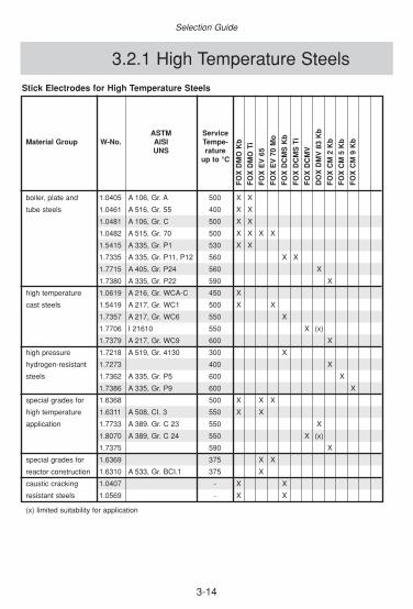
3-14
Selection Guide
3.2.1 High Temperature Steels
Stick Electrodes for High Temperature Steels
ASTM ServiceMaterial Group W-No. AISI Tempe-
UNS ratureup to °C
boiler, plate and 1.0405 A 106, Gr. A 500 X X
tube steels 1.0461 A 516, Gr. 55 400 X X
1.0481 A 106, Gr. C 500 X X
1.0482 A 515, Gr. 70 500 X X X X
1.5415 A 335, Gr. P1 530 X X
1.7335 A 335, Gr. P11, P12 560 X X
1.7715 A 405, Gr. P24 560 X
1.7380 A 335, Gr. P22 590 X
high temperature 1.0619 A 216, Gr. WCA-C 450 X
cast steels 1.5419 A 217, Gr. WC1 500 X X
1.7357 A 217, Gr. WC6 550 X
1.7706 I 21610 550 X (x)
1.7379 A 217, Gr. WC9 600 X
high pressure 1.7218 A 519, Gr. 4130 300 X
hydrogen-resistant 1.7273 400 X
steels 1.7362 A 335, Gr. P5 600 X
1.7386 A 335, Gr. P9 600 X
special grades for 1.6368 500 X X X
high temperature 1.6311 A 508, CI. 3 550 X X
application 1.7733 A 389. Gr. C 23 550 X
1.8070 A 389, Gr. C 24 550 X (x)
1.7375 590 X
special grades for 1.6369 375 X X
reactor construction 1.6310 A 533, Gr. BCI.1 375 X
caustic cracking 1.0407 - X X
resistant steels 1.0569 - X X
(x) limited suitability for application
FO
X D
MO
Kb
FO
X D
MO
Ti
FO
X E
V 6
5
FO
X E
V 7
0 M
o
FO
X D
CM
S K
b
FO
X D
CM
S T
i
FO
X D
CM
V
DO
X D
MV
83
Kb
FO
X C
M 2
Kb
FO
XC
M 5
Kb
FO
X C
M 9
Kb

3-15
Classification-based or Approval-based Selection
DM
O-I
GD
CM
S-I
GD
MV
83-
IGC
M 2
-IG
CM
5-I
GC
M 9
-IG
EM
S 2
Mo
EM
S 2
CrM
oC
M 2
-UP
CM
5-U
PD
MO
DC
MS
GTAW and Gas Welding Rods, GMAW or SAW Wires for High Temperature Steels
ASTM ServiceMaterial Group W-No. AISI Tempe-
UNS ratureup to °C
boiler, plate and 1.0405 A 106, Gr. A 500 X X X
tube steels 1.0461 A 516, Gr. 55 400 X X X
1.0481 A 106, Gr. C 500 X X X
1.0482 A 515, Gr. 70 500 X X X
1.5415 A 335, Gr. P1 530 X X X
1.7335 A 335, Gr. P11, P12 560 X X X
1.7715 A 405, Gr. P24 560 X
1.7380 A 335, Gr. P22 590 X X
high temperature 1.0619 A 216, Gr. WCA-C 450 X X
cast steels 1.5419 A 217, Gr. WC1 500 X X
1.7357 A 217, Gr. WC6 550 X X
1.7706 I 21610 550 (x)
1.7379 A 217, Gr. WC9 600 X X
high pressure 1.7218 A 519, Gr. 4130 300 X X
hydrogen-resistant 1.7273 400 X X
steels 1.7362 A 335, Gr. P5 600 X X
1.7386 A 335, Gr. P9 600 X
special grades for 1.6368 500 X (x)
high temperature 1.6311 A 508, CI. 3 550 X (x)
application 1.7733 A 389. Gr. C 23 550 X (x)
1.8070 A 389, Gr. C 24 550 (x)
1.7375 590 X
special grades for 1.6369 375 X
reactor construction 1.6310 A 533, Gr. BCI.1 375 X
caustic cracking 1.0407 - X X
resistant steels 1.0569 - X X
(x) limited suitability for application

3-16
Selection Guide
3.2.2 Creep-resistant Steels
Stick Electrodes for Creep-resistant Steels
ASTM ServiceMaterial Group W-No. AISI Tempe-
UNS ratureup to °C
high temperature 1.4922 - 600 X (x)2 (x)2
and creep resistant 1.4923 - 580 X (x)2 (x)2
steels 1.4926 - 600 X (x)2 (x)2
1.4931 - 600 X (x)2 (x)2
1.4935 - 580 X (x)2 (x)2
- A 335, Gr. P91 650 X (x)2 (x)2
- A 335, Gr. P911 650 X (x)2 (x)2
- A 335, Gr. P92 650 X (x)2 (x)2
creep-resistant 1.4948 304 H 700 X X (x) (x)
austenitic steels 1.4949 304 N 700 X X (x) (x)
1.4941 - 700 X X (x) (x)
1.4919 316 H 700 (x)1 (x) (x)
1.4910 - 750 (x)1 (x) (x)
1.4961 TP 347 H 750 X (x) (x)
1.4981 - 750 (x)1 (x) (x)
1.4988 - 650 (x)1 (x) (x)
nickel-base alloys 1.4958 - 700 (x) (x)
1.4959 - 1000 (x) (x)
X = same or similar alloyed filler metals(x) = dissimilar alloyed filler metals1 = weld metal contains no molybdenum, corrosion resistance requirements have to be checked2 = strength values of weld metal are lower than base material
FO
X 2
0 M
VW
FO
X C
9 M
V
FO
X C
9 M
VW
FO
X P
92
FO
X C
N 1
8/11
FO
X E
308
H
FO
X C
N 1
6/13
FO
X N
IBA
S 7
0/20
FO
X N
IBA
S 7
0/15

3-17
Selection Tables
GTAW Rods, GMAW and SAW Wires for Creep-resistant Steels
ASTM ServiceMaterial Group W-No. AISI Tempe-
UNS raturup to °C
high temperature 1.4922 - 600 X (x)2 X
and creep resistant 1.4923 - 580 X (x)2 X
steels 1.4926 - 600 X (x)2 X
1.4931 - 600 X (x)2 X
1.4935 - 580 X (x)2 X
- A 335, Gr. P91 650 X (x)2 X
- A 335, Gr. P911 650 X (x)2
- A 335, Gr. P92 650 X (x)2 X
creep-resistant 1.4948 304 H 700 X X X (x)
austenitic 1.4949 304 N 700 X X X (x)
steels 1.4941 - 700 X X X (x)
1.4919 316 H 700 (x)1 (x)
1.4910 - 750 (x)1 (x)
1.4961 TP 347 H 750 X (x)
1.4981 - 750 (x)1 (x)
1.4988 - 650 (x)1 (x)
nickel-base alloys 1.4958 - 700 (x)
1.4959 - 1000 (x)
X = same or similar alloyed filler metals(x) = dissimilar alloyed filler metals1 = weld metal contains no molybdenum, corrosion resistance requirements have to be checked2 = strength values of weld metal are lower than base material* suitable sub-arc welding fluxes can be found in the data sheets of SAW wire
20 M
VW
-IG
C 9
MV
-IG
C 9
MV
W-I
GP
92-I
GC
N 1
8/11
-IG
ER
308
H-I
GC
N 1
6/13
-IG
E 3
08 H
-FD
, E 3
08 H
PW
-FD
NIB
AS
70/
20-I
GN
IBA
S 7
0/20
-FD
20 M
VW
-UP
*C
9 M
V-U
P*
P92
-UP
*

Recommendations for suitable filler metals and optimum heat treatment
Base Material CombinationFiller Metals1) Annealing
Stick Electrodes GTAW/GMAW SAW temp.2) °C
P235G1TH 16Mo3 FOX SPEM EML 5 EMS 2 530-600
P255G1TH FOX EV 47 EMK 6 EMS 3
FOX EV 50 EMK 7 – EMK 8 EMS 2 Mo
FOX DMO Kb or Ti DMO-IG
DMO Kb-FD, DMO Ti-FD
P295GH 16Mo3 FOX EV 47 EML 5 EMS 2 530-580
FOX EV 50 EMK 6 EMS 3
FOX DMO Kb or Ti EMK 7 - EMK 8
DMO-IG
DMO Kb-FD, DMO Ti-FD
P310GH 16Mo3 FOX DMO Kb or Ti EML 5 EMS 3 530-580
EMK 6 EMS 2 Mo
EMK 7 – EMK 8
DMO-IG
DMO Kb-FD, DMO Ti-FD
P235G1TH 13CrMo4-5 FOX EV 47 EML 5 540-600
P255G1TH FOX EV 50 EMK 6
FOX DMO Kb or Ti EMK 7 – EMK 8
DMO-IG
DMO Kb-FD, DMO Ti-FD
16Mo3 13CrMo4-5 FOX DMO Kb or Ti DMO-IG EMS 2 Mo 550-620
DMO Kb-FD, DMO Ti-FD
16Mo3 10CrMo9-10 FOX DMO Kb or Ti DMO-IG EMS 2 Mo 570-620
DMO Kb-FD, DMO Ti-FD
13CrMo4-5 10CrMo9-10 FOX DCMS Kb DCMS-IG (EMS 2 CrMo) 650-720
DCMS Kb-FD
14MoV6-3 13CrMo4-5 FOX DCMS Kb DCMS-IG EMS 2 CrMo 680-720
DCMS Kb-FD
14MoV6-3 10CrMo9-10 FOX CM 2 Kb CM 2-IG (CM 2-UP) 690-730
CM 2 Kb-FD
14MoV6-3 X20CrMoV12-1 FOX DMV 83 Kb DMV 83-IG 670-720
FOX 20 MVW 20 MVW-IG
3-18
Selection Guide
3.2.3 Dissimilar Welds with High Temperature Steels

3-19
Selection Tables
Recommendations for suitable filler metals and optimum heat treatment (continued)
Base Material CombinationFiller Metals1) Annealing
Stick Electrodes GTAW/GMAW SAW temp.2) °C
10CrMo9-10 X20CrMoV12-1 FOX CM 2 Kb or CM 2-IG or (CM 2-UP) 700-750
FOX NIBAS 70/20 or NIBAS 70/20-IG or
FOX NiCr 70 Nb NiCr 70 Nb-IG
FOX DMV 83 Kb DMV 83-IG 680-730
FOX 20 MVW 20 MVW-IG 20 MVW-UP 700-750
17 MnMoV 74 P235G1TH FOX DMO Kb or Ti DMO-IG EMS 2 Mo 530-590
P255G1TH DMO Kb-FD, DMO Ti-FD
16Mo3
15 NiCuMoNb 5 13CrMo4-5
11 NiMoV 53 P235G1TH FOX DMO Kb or Ti DMO-IG EMS 2 Mo 530-590
P255G1TH DMO Kb-FD, DMO Ti-FD
16Mo3
13CrMo4-5
20MnMoNi4-5 P235G1TH FOX DMO Kb or Ti DMO-IG EMS 2 Mo 550-600
P255G1TH DMO Kb-FD, DMO Ti-FD
16Mo3
13CrMo4-5 FOX DMO Kb or Ti DMO-IG EMS 2 Mo 530-590
DMO Kb-FD, DMO Ti-FD
FOX DCMS Kb DCMS-IG
DCMS Kb-FD MS 2 CrMo
15 MnMoNiV 53 P235G1TH FOX DMO Kb or Ti DMO-IG EMS 2 Mo 530-590
P255G1TH DMO Kb-FD, DMO Ti-FD
16Mo3
13CrMo4-5
22 NiMoCr 37 P235G1TH FOX DMO Kb or Ti DMO-IG EMS 2 Mo 580-640
P255G1TH DMO Kb-FD, DMO Ti-FD
16Mo3
13CrMo4-5
GP240GH P235G1TH FOX EV 47 or EML 5 EMS 2 560-620
P255G1TH FOX EV 50 EMK 6 EMS 3
EMK 7
16Mo3 FOX DMO Kb or Ti DMO-IG EMS 2 Mo 560-620
DMO Kb-FD, DMO Ti-FD
22Mo4 16Mo3 FOX DMO Kb or Ti DMO-IG EMS 2 Mo 560-620
DMO Kb-FD, DMO Ti-FD
13CrMo4-5 FOX DMO Kb or Ti DMO-IG EMS 2 Mo 560-620
FOX DCMS Kb DCMS-IG EMS 2 CrMo
22Mo4 21 CrMoV 511 FOX DCMS Kb DCMS-IG EMS 2 CrMo 650-720
DCMS Kb-FD

3-20
Selection Guide
Recommendations for suitable filler metals and optimum heat treatment (continued)
Base Material CombinationFiller Metals1) Annealing
Stick Electrodes GTAW/GMAW SAW temp.2) °C
G17CrMo5-5 16Mo3 FOX DMO Kb DMO-IG EMS 2 Mo 640-700
DMO Kb-FD, DMO Ti-FD
13CrMo4-5 FOX DCMS Kb DCMS-IG EMS 2 CrMo 640-700
10CrMo9-10 DCMS Kb-FD
14MoV6-3 670-720
G17CrMoV5-11 13CrMo4-5 FOX DCMS Kb DCMS-IG EMS 2 CrMo 650-730
DCMS Kb-FD
10CrMo9-10 FOX CM 2 Kb CM 2-IG CM 2-UP 670-720
CM 2 Kb-FD
14MoV6-3 FOX DMV 83 Kb DMV 83-IG (CM 2-UP) 680-730
FOX CM 2 Kb CM 2-IG
CM 2 Kb-FD
21CrMoV5-1-1 FOX DMV 83 Kb DMV 83-IG
X8CrNiNb16-13 FOX NIBAS 70/20 NIBAS 70/20-IG
FOX NiCr 70 Nb NiCr 70 Nb-IG
X20CrMoV12-1 FOX DMV 83 Kb DMV 83-IG
FOX 20 MVW 20 MVW-IG
FOX NiCr 70 Nb NiCr 70 Nb-IG
FOX NIBAS 70/20 NIBAS 70/20-IG
GX22CrMoV12-1 14MoV6-3 FOX CM 2 Kb DMV 83-IG 670-730
FOX NIBAS 70/20 NIBAS 70/20-IG
FOX NiCr 70 Nb NiCr 70 Nb-IG
14MoV6-3 FOX DMV 83 Kb DMV 83-IG 680-730
FOX NIBAS 70/20 NIBAS 70/20-IG
FOX NiCr 70 Nb NiCr 70 Nb-IG
21CrMoV5-1-1 FOX DMV 83 Kb 20 MVW-IG 670-730
FOX NIBAS 70/20 NIBAS 70/20-IG
FOX NiCr 70 Nb NiCr 70 Nb-IG
X20CrMoV12-1 FOX 20 MVW
FOX NIBAS 70/20 NIBAS 70/20-IG
FOX NiCr 70 Nb NiCr 70 Nb-IG
X8CrNiNb16-13 FOX NiCr 70 Nb NiCr 70 Nb-IG
FOX NIBAS 70/20 NIBAS 70/20-IG
( ) Use subject with reservations. Before selection please consult your next BÖHLER representative and give exact description of service conditions and requirements.
1) The material recommendations have been chosen in a way to ensure that the relevant filler metal is lower alloyed and thus tougher than the base metal.
2) The annealing temperatures have been chosen in a way to ensure that the lowest Ac1 temperature of the two materials involved is not exceeded. The annealing time depends on the relevant work piece thickness; it has tobe at least 15 minutes for thicknesses of 15 mm, at least 30 minutes for thicknesses of 15-20 mm and at least 60 minutes for thicknesses above 30 mm. For work pieces of low thicknesses a medium annealing time shouldbe chosen, whereas in thick-walled components the surface should be reach a temperature within the upper range.

3-21
NotesNotes

3-22
Selection Guide
3.2.4 Ferritic Chromium Steels
Stick Electrodes for Ferritic Chromium Steels
materialASTM
W-No. AISIdesignation
UNS
1.4000 X6Cr13 403 (x) (x) X X X X X
1,4001 X7Cr14 429 (x) (x) X X X X X
1.4002 X6CrAl13 405 (x) (x) X X
1.4003 X2CrNi12 X X
1.4006 X12Cr13 410 (x) (x) X X X X X
1.4008 GX8CrNi13 CA 15 (x) (x) X X X X X
1.4016 X6Cr17 430 (x) X X X X X
1.4021 X20Cr13 420 (x) (x) X X X X X
1.4024 X15Cr13 410 (x) (x) X X X X X
1.4027 GX20Cr14 A 217 X X X X
1.4034 X46Cr13 X X X X
1.4057 X17CrNi16-2 431 X (x) X X X X X X
1.4059 GX22CrNi17 A 743 X (x) X X X X X X
1.4113 X6CrMo17-1 434 (x) X X X X
1.4120 X20CrMo13 (x) X X X X
1.4120 GX20CrMo13 (x) X X X X
1.4122 X39CrMo17-1 X X X X X
1.4122 GX35CrMo17-1 X X X X X
FO
X K
W 1
0
FO
X S
KW
A
FO
X S
KW
AM
FO
X A
7, -
A
FO
X C
N 1
9/9
M
FO
X C
N 2
3/12
-A
FO
X C
N 2
3/12
Mo
-A
FO
X C
N 2
9/9,
-A
FO
X E
AS
2, -
A, -
VD
FO
X E
AS
4M
, -A
, -T
S, -
VD
FO
X S
AS
2, -
A
FO
X S
AS
4, -
A
FO
X N
IBA
S 7
0/20
FO
X N
iCr
70 N
b
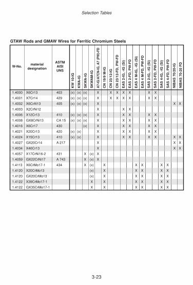
3-23
Selection Tables
GTAW Rods and GMAW Wires for Ferritic Chromium Steels
materialASTM
W-No. AISIdesignation
UNS
1.4000 X6Cr13 403 (x) (x) (x) X X X X X X X
1,4001 X7Cr14 429 (x) (x) (x) X X X X X X X
1.4002 X6CrAl13 405 (x) (x) (x) X X X
1.4003 X2CrNi12 X X X
1.4006 X12Cr13 410 (x) (x) (x) X X X X X
1.4008 GX8CrNi13 CA 15 (x) (x) (x) X X X X X
1.4016 X6Cr17 430 (x) X X X X X
1.4021 X20Cr13 420 (x) (x) X X X X X
1.4024 X15Cr13 410 (x) (x) X X X X X X X
1.4027 GX20Cr14 A 217 X X X
1.4034 X46Cr13 X X X
1.4057 X17CrNi16-2 431 X (x) X
1.4059 GX22CrNi17 A 743 X (x) X
1.4113 X6CrMo17-1 434 X (x) X X X X X
1.4120 X20CrMo13 (x) X X X X X
1.4120 GX20CrMo13 (x) X X X X X
1.4122 X39CrMo17-1 X X X X X X
1.4122 GX35CrMo17-1 X X X X X X
KW
10-
IG
KW
A-I
G
SK
WA
-IG
SK
WA
M-I
G
A7-
IG/A
7CN
-IG, A
7 (P
W)-
FD
CN
19/
9 M
-IG
CN
23/
12-I
G
CN
23/
12-F
D, P
W-F
D
EA
S 2
-IG
, -IG
(S
i)
EA
S 2
-FD
, PW
-FD
EA
S 4
M-I
G, -
IG (
Si)
EA
S 4
M-F
D, P
W-F
D
SA
S 2
-IG
, -IG
(S
i)
SA
S 2
-FD
, PW
-FD
SA
S 4
-IG
, -IG
(S
i)
SA
S 4
-FD
, PW
-FD
NIB
AS
70/
20-I
G
NIB
AS
70-
20 F
D

3-24
Selection Guide
3.2.5 Chemical Resistant Steels
Stick Electrodes for Chemical Resistant Steels
ASTMW-No. material designation AISI
UNS
1.3952 X2CrNiMoN18-14-3 X
1.3964 X2CrNiMnMoNNb21-16-5-3 S20910 X
1.4301 X5CrNi18-10 304 X (x)
1.4303 X4CrNi18-12 305 X (x)
1.4306 X2CrNi19-11 304L X (x)
1.4308 GX5CrNi19-10 X (x)
1.4311 X2CrNiN18-10 304LN X (x)
1.4312 GX10CrNi18-8 X (x)
1.4313 X3CrNiMo13-4 S41500 X
1.4317 G-X 4CrNi 13-4 X
1.4361 X1CrNiSi18-15-4 X
1.4401 X5CrNiMo17-12-2 316 X (x)
1.4404 X2CrNiMo17-12-2 316L X (x)
1.4406 X2CrNiMoN17-11-2 316L (x) X (x)
1.4407 GX5CrNiMo13-4 CAGNM X
1.4408 GX5CrNiMo19-11-2 X (x)
1.4409 GX2CrNiMo19-11-2 X (x)
1.4429 X2CrNiMoN17-13-3 316LN (x) X (x)
1.4435 X2CrNiMo18-14-3 317L (x) X (x)
1.4436 X3CrNiMo17-13-3 S31600 (x) X (x)
1.4437 GX6CrNiMo18-12 S31600 (x) X (x)
1.4438 X2CrNiMo18-15-4 S31703 (x) (x)
1.4439 X2CrNiMoN17-13-5 S 31726 (x) (x) (x)
1.4446 GX2CrNiMoN17-13-4 (x) (x)
1.4448 GX6CrNiMo17-13 (x) (x)
1.4462 X2CrNiMoN22-5-3 S31803 X
1.4500 GX7NiCrMoCuNb25-20 X
1.4505 X4NiCrMoCuNb20-18-2 (x)
1.4506 X5NiCrMoCuTi20-18 (x)
1.4510 X3CrTi17 430 Ti (x) X
FO
X A
M 4
00
FO
X A
SN
5, -
A
FO
X C
N 1
3/4,
(-S
up
ra)
FO
X C
N 2
0/25
M, -
A
FO
X
CN
22/
9 N
, -B
FO
X E
AS
2, -
A, -
VD
FO
X E
AS
2 S
i
FO
X E
AS
4M
, -A
, -T
S, -
VD
FO
X N
IBA
S 6
25
FO
X N
iCr
625
FO
X S
AS
2, -
A
FO
X S
AS
4, -
A
FO
X S
KW
A

3-25
Selection Tables
Stick Electrodes for Chemical Resistant Steels (continued).
ASTMW-No. material designation AISI
UNS
1.4511 X3CrNb17 430 Cb (x) X
1.4512 X2CrTi12 S40900 (x) (x)
1.4529 X1NiCrMoCuN25-20-7 N08925 X X
1.4531 GX2NiCrMoCuN20-18 (x)
1.4536 GX2NiCrMoCuN25-20 X (x) (x)
1.4539 X1NiCrMoCu25-20-5 N08904 X (x) (x)
1.4541 X6CrNiTi18-10 321 (x) X
1.4550 X6CrNiNb18-10 347 (x) X
1.4552 GX5CrNiNb19-11 CF8C (x) X
1.4558 X2NiCrAlTi32-20 B407 (x) (x)
1.4571 X6CrNiMoTi17-12-2 316 Ti (x) X
1.4577 X3CrNiMoTi25-25 S31640 (x)
1.4580 X6CrNiMoNb17-12-2 316 Cb (x) X
1.4581 GX5CrNiMoNb19-11-2 (x) X
1.4583 X10CrNiMoNb18-12 316 Cb X
1.4585 GX7CrNiMoCuNb18-18 (x)
1.4586 X5NiCrMoCuNb22-18 (x)
2.4856 NiCr22Mo9Nb N06625 X X
2.4858 NiCr21Mo N08825 (x) (x)
FO
X A
M 4
00
FO
X A
SN
5, -
A
FO
X C
N 1
3/4,
(-S
up
ra)
FO
X C
N 2
0/25
M, -
A
FO
X
CN
22/
9 N
, -B
FO
X E
AS
2, -
A, -
VD
FO
X E
AS
2 S
i
FO
X E
AS
4M
, -A
, -T
S, -
VD
FO
X N
IBA
S 6
25
FO
X N
iCr
625
FO
X S
AS
2, -
A
FO
X S
AS
4, -
A
FO
X S
KW
A

3-26
Selection Guide
GTAW Rods, GMAW Wires for Chemical Resistant Steels
materialASTM
W-No. AISIdesignation
UNS
1.3952 X2CrNiMoN18-14-3 X
1.3964 X2CrNiMnMoNNb21-16-5-3 S20910 X
1.4301 X5CrNi18-10 304 X X (x)
1.4303 X4CrNi18-12 305 X X (x)
1.4306 X2CrNi19-11 304L X X (x)
1.4308 GX5CrNi19-10 X X (x)
1.4311 X2CrNiN18-10 304LN X X (x)
1.4312 GX10CrNi18-8 X X (x)
1.4313 X3CrNiMo13-4 S41500 X
1.4361 X1CrNiSi18-15-4 X
1.4401 X5CrNiMo17-12-2 316 X X (x)
1.4404 X2CrNiMo17-12-2 316L X X (x)
1.4406 X2CrNiMoN17-11-2 316L (x) X X (x)
1.4407 GX5CrNiMo13-4 CAGNM X
1.4408 GX5CrNiMo19-11-2 X X (x)
1.4409 GX2CrNiMo19-11-2 X X (x)
1.4429 X2CrNiMoN17-13-3 316LN (x) X X X (x)
1.4435 X2CrNiMo18-14-3 317L (x) X X X (x)
1.4436 X3CrNiMo17-13-3 S31600 (x) X X X (x)
1.4437 GX6CrNiMo18-12 S31600 (x) X X (x)
1.4438 X2CrNiMo18-15-4 S31703 X X (x)
1.4439 X2CrNiMoN17-13-5 S 31726 X (x)
1.4446 GX2CrNiMoN17-13-4 X (x)
1.4448 GX6CrNiMo17-13 X (x)
1.4462 X2CrNiMoN22-5-3 S31803 X X
1.4500 GX7NiCrMoCuNb25-20 (x)
1.4505 X4NiCrMoCuNb20-18-2 (x)
1.4506 X5NiCrMoCuTi20-18 (x)
1.4510 X3CrTi17 430 Ti (x) X
1.4511 X3CrNb17 430 Cb (x) X
1.4512 X2CrTi12 S40900 (x) (x)
1.4529 X1NiCrMoCuN25-20-7 N08925 X
AM
400
-IG
AS
N 5
-IG
, -IG
(Si)
E 3
17L
-FD
, E 3
17L
PW
-FD
CN
13/
4-IG
, CN
13/
4-M
C
CN
20/
25M
-IG
, -IG
(Si)
CN
22/
9N-I
G
CN
22/
9 N
-FD
, PW
-FD
EA
S 2
-FD
, -P
W-F
D
EA
S 2
-IG
, -IG
(Si)
EA
SN
2 S
i-IG
EA
S 4
M-I
G, -
IG(S
i)
EA
S 4
M-F
D, P
W-F
D
NIB
AS
625
-IG, N
iCr
625-
IG
SA
S 2
-IG, -
IG(S
i), -F
D, P
W-F
D
SA
S 4
-IG, -
IG(S
i), -F
D, P
W-F
D
SK
WA
-IG

3-27
Selection Tables
GTAW Rods, GMAW Wires for Chemical Resistant Steels (continued)
materialASTM
W-No. AISIdesignation
UNS
1.4531 GX2NiCrMoCuN20-18 (x)
1.4536 GX2NiCrMoCuN25-20 X (x)
1.4539 X1NiCrMoCu25-20-5 N08904 X (x)
1.4541 X6CrNiTi18-10 321 (x) (x) X X
1.4550 X6CrNiNb18-10 347 (x) (x) X X
1.4552 GX5CrNiNb19-11 CF8C (x) (x) X X
1.4558 X2NiCrAlTi32-20 B407 (x)
1.4571 X6CrNiMoTi17-12-2 316 Ti (x) (x) X X
1.4577 X3CrNiMoTi25-25 S31640 (x)
1.4580 X6CrNiMoNb17-12-2 316 Cb (x) (x) X X
1.4581 GX5CrNiMoNb19-11-2 (x) (x) X X
1.4583 X10CrNiMoNb18-12 316 Cb (x) (x) X X
1.4585 GX7CrNiMoCuNb18-18 (x)
1.4586 X5NiCrMoCuNb22-18 (x)
2.4856 NiCr22Mo9Nb N06625 X
2.4858 NiCr21Mo N08825 X
AM
400
-IG
AS
N 5
-IG
, -IG
(Si)
CN
13/
4-IG
, CN
13/
4-M
C
CN
20/
25M
-IG
, -IG
(Si)
CN
22/
9N-I
G, -
FD
, PW
-FD
EA
S 2
-FD
, PW
-FD
EA
S 2
-IG
, -IG
(Si)
EA
SN
2 S
i-IG
EA
S 4
M-I
G, -
IG(S
i)
EA
S 4
M-F
D, P
W-F
D
NIB
AS
625
-IG
NiC
r 62
5-IG
SA
S 2
-IG
, -IG
(Si)
SA
S 2
-FD
, PW
-FD
SA
S 4
-IG
, -IG
(Si)
SA
S 4
-FD
, PW
-FD
SK
WA
-IG

3-28
Selection Guide
Sub-arc Wire/Flux Combinations for Chemical Resistant Steels
ASTMW-No material designation AISI
UNS
1.3952 X2CrNiMoN18-14-3 (x)
1.3964 X2CrNiMnMoNNb21-16-5-3 S20910 (x)
1.4301 X5CrNi18-10 304 X (x)
1.4303 X4CrNi18-12 305 X (x)
1.4306 X2CrNi19-11 304L X (x)
1.4308 GX5CrNi19-10 X (x)
1.4311 X2CrNiN18-10 304LN X (x)
1.4312 GX10CrNi18-8 X (x)
1.4313 X3CrNiMo13-4 S41500 X
1.4401 X5CrNiMo17-12-2 316 X (x)
1.4404 X2CrNiMo17-12-2 316L X (x)
1.4406 X2CrNiMoN17-11-2 316L (x) X (x)
1.4407 GX5CrNiMo13-4 CAGNM X
1.4408 GX5CrNiMo19-11-2 X (x)
1.4409 GX2CrNiMo19-11-2 X (x)
1.4429 X2CrNiMoN17-13-3 316LN (x) X (x)
1.4435 X2CrNiMo18-14-3 317L (x) X (x)
1.4436 X3CrNiMo17-13-3 S31600 (x) X (x)
1.4437 GX6CrNiMo18-12 S31600 (x) X (x)
1.4438 X2CrNiMo18-15-4 S31703 X (x)
1.4439 X2CrNiMoN17-13-5 S 31726 X (x)
1.4446 GX2CrNiMoN17-13-4 X (x)
1.4448 GX6CrNiMo17-13 X (x)
1.4462 X2CrNiMoN22-5-3 S31803 X
1.4500 GX7NiCrMoCuNb25-20 X
1.4505 X4NiCrMoCuNb20-18-2 (x)
1.4506 X5NiCrMoCuTi20-18 (x)
1.4510 X3CrTi17 430 Ti (x)
1.4511 X3CrNb17 430 Cb (x)
1.4512 X2CrTi12 S40900 (x)
1.4529 X1NiCrMoCuN25-20-7 N08925 (x)
AS
N 5
-UP
/BB
203
CN
13/
4-U
P/B
B 2
03
CN
20/
25M
-UP
/BB
203
CN
22/
9N-U
P/B
B 2
02
EA
S 2
-UP
/BB
202
EA
S 4
M-U
P/B
B 2
02
SA
S 2
-UP
/BB
202
SA
S 4
-UP
/BB
202
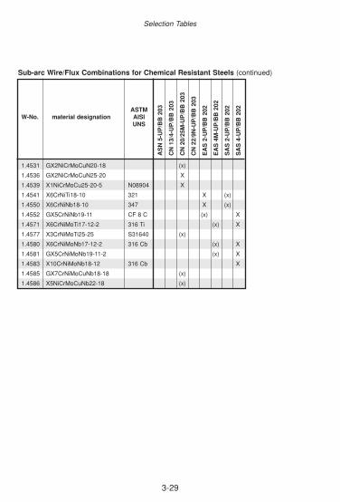
3-29
Selection Tables
Sub-arc Wire/Flux Combinations for Chemical Resistant Steels (continued)
ASTMW-No. material designation AISI
UNS
1.4531 GX2NiCrMoCuN20-18 (x)
1.4536 GX2NiCrMoCuN25-20 X
1.4539 X1NiCrMoCu25-20-5 N08904 X
1.4541 X6CrNiTi18-10 321 X (x)
1.4550 X6CrNiNb18-10 347 X (x)
1.4552 GX5CrNiNb19-11 CF 8 C (x) X
1.4571 X6CrNiMoTi17-12-2 316 Ti (x) X
1.4577 X3CrNiMoTi25-25 S31640 (x)
1.4580 X6CrNiMoNb17-12-2 316 Cb (x) X
1.4581 GX5CrNiMoNb19-11-2 (x) X
1.4583 X10CrNiMoNb18-12 316 Cb X
1.4585 GX7CrNiMoCuNb18-18 (x)
1.4586 X5NiCrMoCuNb22-18 (x)
AS
N 5
-UP
/BB
203
CN
13/
4-U
P/B
B 2
03
CN
20/
25M
-UP
/BB
203
CN
22/
9N-U
P/B
B 2
03
EA
S 2
-UP
/BB
202
EA
S 4
M-U
P/B
B 2
02
SA
S 2
-UP
/BB
202
SA
S 4
-UP
/BB
202

3-30
Selection Guide
3.2.6 Heat Resistant Steels
Stick Electrodes for Heat Resistant Steels
ASTM ServiceMaterial Group W-No AISI Tempe-
UNS ratureup to °C
heat resistant steels 1.4710 2 850 (x) (x)1 (x)1
1.4712 850 (x) (x)1 (x)1
1.4713 800 (x) (x)1 (x)1
1.4724 405 850 (x) (x)1 (x)1
1.4729 2 900 (x) (x)1 (x)1 (x)1
1.4740 2 950 (x) (x)1 (x)1 (x)1
1.4742 430 1050 (x) (x)1
1.47452 1050 (x) (x)1 (x)1 (x)1
1.4762 446 1200 X (x)1
1.4821 327 1100 X (x)1
1.4822 2 1100 X (x)1
1.4825 A 297, Gr. CF20 800 (x) X3 (x)
1.4826 A 297, Gr. HF 950 X (x)
1.4828 309 1050 X (x)1
1.4832 1000 X (x) (x) (x)
1.4837 A 297, Gr. HH 1150 X (x) (x)
1.4841 314, 310 1150 X
1.4845 310 1050 X
1.4861 1200 (x) (x)
1.4864 330 1100 (x) (x)
1.4865 330 1120 (x) (x)
1.4876 B163 1150 (x) (x)
1.4878 321 800 X3 (x)
1.0569 - X X
X = same or similar alloyed filler metal(x) = dissimilar or higher alloyed filler metal (please check the service requirements)1 = austenitic weld deposit with higher ductility; application in sulphur-containing environment or similar-colour requirement demands the usage of similar alloyed welding consumables 2 = weldability of base material is limited3 = in the case of service temperatures above 400°C FOX CN 18/11, FOX E 308 H or FOX NIBAS70/20 has to be used
FO
X F
A
FO
X F
F, -
A
FO
X F
FB
, -A
FO
X S
AS
2, -
A
FO
X A
7, -
A
FO
X N
IBA
S 7
0/20
FO
X N
iCr
70 N
B
FO
X N
IBA
S 7
0/15
FO
X N
iCr
70/1
5

3-31
Selection Tables
GTAW Rods and GMAW Wires for Heat Resistant Steels
ASTM ServiceMaterial Group W-No. AISI Tempe-
UNS ratureup to °C
heat resistant steels 1.4710 2 850 (x) (x)1 (x)1 (x)1
1.4712 850 (x) (x)1 (x)1 (x)1
1.4713 800 (x) (x)1 (x)1 (x)1
1.4724 405 850 (x) (x)1 (x)1 (x)1
1.4729 2 900 (x) (x)1 (x)1 (x)1
1.4740 2 950 (x) (x)1 (x)1 (x)1
1.4742 430 1050 (x) (x)1
1.4745 2 1050 (x) (x)1 (x)1 (x)1
1.4762 446 1200 X (x)1
1.4821 327 1100 X (x)1
1.4822 2 1100 X (x)1
1.4825 A 297, Gr. CF20 800 (x) X3 X3 (x) (x)
1.4826 A 297, Gr. HF 950 X (x)
1.4828 309 1050 X (x)1
1.4832 1000 X (x) (x) (x)
1.4837 A 297, Gr. HH 1150 X (x) (x)
1.4841 314, 310 1150 X
1.4845 310 1050 X
1.4861 1200 (x) (x)
1.4864 330 1100 (x) (x)
1.4865 330 1120 (x) (x)
1.4876 B163 1150 (x) (x)
1.4878 321 800 X3 X3 (x) (x)
1.0569 - X X
X = same or similar alloyed filler metal(x) = dissimilar or higher alloyed filler metal (please check the service requirements)1 = austenitic weld deposit with higher ductility; application in sulphur-containing environment orsimilar-colour requirement demands the usage of similar alloyed welding consumables 2 = weldability of base material is limited3 = in the case of service temperatures above 400°C CN 18/11-IG, ER 308 H-IG, E 308 H-FD, E308 H PW-FD or NIBAS 70/20IG has to be used
FA-I
G
FF
-IG
FF
B-I
G
SA
S 2
-IG
, -IG
(S
I)
SA
S 2
-FD
, PW
-FD
A7
CN
-IG
A7-
IG, -
FD
, PW
-FD
NIB
AS
70/
20-I
G
NIB
AS
70/
20-F
D
3-32
NotesNotes

3-33
OverviewThe choice of welding process is a significant point in the construction of aneconomic weld. This section therefore attempts to characterise briefly thevarious welding procedures pointing out the most important advantages anddisadvantages.
Content
3.3.1 MANUAL METAL ARC WELDING
WITH COVERED ELECTRODES . . . . . . . . . . . . . . . . . . . . . . . . . . .34
3.3.2 GAS SHIELDED TUNGSTEN ARC WELDING (TIG-PROCESS) . . .36
3.3.3 GAS SHIELDED METAL ARC WELDING (MIG/MAG-PROCESS) . .37
3.3.4 GAS SHIELDED METAL ARC WELDING
WITH FLUX-CORED WIRES . . . . . . . . . . . . . . . . . . . . . . . . . . . . . . .41
3.3.5 RECOMMENDATIONS FOR SUBMERGED ARC WELDING
USING SOLID WIRES . . . . . . . . . . . . . . . . . . . . . . . . . . . . . . . . . . . .43
3.3. Process-based Selection of Consumables
Selection Tables

3-34
In manual metal arc welding using coated stick electrodes, the coating assumes the functionof a protective gas shield on one hand and of forming a slag on the other, thereby protectingthe metal droplets transferred and the weld metal in turn against contact with atmospheric oxy-gen. Further functions of the coating are de-oxidation of the weld metal, increasing the metalrecovery, offsetting burn-off and ensuring good flow behaviour.
In practical use there are three significant types of coating: rutile, basic and cellulose coatedstick electrodes as well as mixtures of these.
Rutile-coated stick electrode (R)This type of coating is the one most commonly used in practice. The reason for this is foundin a series of advantages such as:• Easier handling for the welder• May be welded with direct and alternating current• Good starting and re-starting properties• Suitable for all welding positions – depending on the type and thickness of coating • Good slag removal properties• Not susceptible to moisture (only applies however to non-alloy and low-alloy types)
The disadvantages of rutile-coated stick electrodes are:• Not suitable for thick-walled components (above 20-25 mm)• Low notch toughness at temperatures below zero• Higher hydrogen contents (20 ml/100 g weld metal)• Not suitable for high-carbon steels (C < 0.2 %)
Basic-coated stick electrode (B)Basic-coated stick electrodes stand out for their excellent ductility properties above all in thelow-temperature range. Other advantages are:• Extremely low hydrogen content (< 5 ml/100 g)• Suitable for all wall thicknesses • Also suitable for welding high-carbon steels (C > 0.2 %).
Disadvantages are:• Slightly more difficult handling for the welder• In part only weldable with direct current• Less favourable slag removal properties and rougher weld surface • Certain amount of susceptibility to moisture absorption
3.3.1 Manual Metal Arc Welding with Covered Electrodes
Selection Guide

3-35
Cellulose-coated stick electrode (C)This type of coating was specially developed for vertical-down welding of large pipes. An arcwith high stability and intensity is generated due to the large proportion of cellulose in the coa-ting. This ensures pore-free welds and reliable root fusion even at high welding speeds andlarger electrode diameters.
The mechanical property values are comparable with those of the basic-coated stick electro-des. However, due to the organic constituents in the coating the hydrogen content of the weldmetal is considerably higher (50 ml/100 g), therefore attention must be paid to good weldabi-lity of the parent metals and the welding technology must be suitably matched (pre-heating).
Mixed types (RC, RB)In addition to these three important basic types there is a large number of so-called “mixedtypes” such as RC or RB coatings. The aim of these is to combine as many positive charac-teristics as possible in one stick electrode.
Coated stick electrodes are universally suitable in practically all materials with good weldabi-lity. The cost of equipment is relatively small although the economic profitability of this proce-dure is deemed poor due to the low deposition rate.
Process-based Selection of Consumables

3-36
In TIG welding an arc burning under the protection of an inert gas is used as the heat source.Pure tungsten rods or tungsten rods alloyed with cerium or thorium are used as the electrode.
The shielding gas consists of argon, helium or argon and helium mixtures with a minimumpurity of 99.95 %. In this case the shielding gas fulfils several functions. It protects the highlyheated tungsten electrode against oxidation by atmospheric oxygen, cools it down and ena-bles the formation of a stable arc. At the same time the liquid weld pool and the filler wire bur-ning off are also shielded from the ambient air.
During TIG welding the filler metal is introduced into the arc laterally at zero current. Rodsapproximately 1 m in length are used as filler metals for manual welding and wires coiled ontorolls are used for mechanised TIG welding.
C-Mn steels as well as low-alloy and high-alloy steels are welded almost exclusively withdirect current and the negative pole on the electrode. From the following table it is possible todetermine how high the load on the tungsten electrodes can be depending on diameter:
3.3.2 Gas Shielded Tungsten Arc Welding (TIG-Process)
The scope of application stretches from the welding of thin sheet metal in non-alloy to high-alloy qualities and to high-grade root welding in thicker plates and tubes in the materials refer-red to previously.
diameter of rodø [mm]
amperage(direct current polarity negative) [A]
pure-tungsten thorium-coatedelectrode electrodes
1.0 25 - 170 max. 801.6 50 - 110 15 - 1502.4 80 - 160 50 - 2203.2 120 - 220 80 - 3204.0 150 - 300 120 - 400
Selection Guide
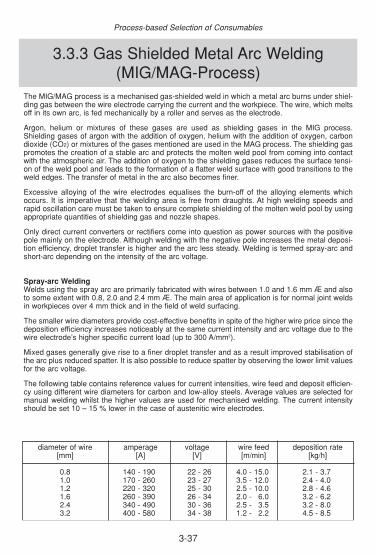
3-37
The MIG/MAG process is a mechanised gas-shielded weld in which a metal arc burns under shiel-ding gas between the wire electrode carrying the current and the workpiece. The wire, which meltsoff in its own arc, is fed mechanically by a roller and serves as the electrode.
Argon, helium or mixtures of these gases are used as shielding gases in the MIG process.Shielding gases of argon with the addition of oxygen, helium with the addition of oxygen, carbondioxide (CO2) or mixtures of the gases mentioned are used in the MAG process. The shielding gaspromotes the creation of a stable arc and protects the molten weld pool from coming into contactwith the atmospheric air. The addition of oxygen to the shielding gases reduces the surface tensi-on of the weld pool and leads to the formation of a flatter weld surface with good transitions to theweld edges. The transfer of metal in the arc also becomes finer.
Excessive alloying of the wire electrodes equalises the burn-off of the alloying elements whichoccurs. It is imperative that the welding area is free from draughts. At high welding speeds andrapid oscillation care must be taken to ensure complete shielding of the molten weld pool by usingappropriate quantities of shielding gas and nozzle shapes.
Only direct current converters or rectifiers come into question as power sources with the positivepole mainly on the electrode. Although welding with the negative pole increases the metal deposi-tion efficiency, droplet transfer is higher and the arc less steady. Welding is termed spray-arc andshort-arc depending on the intensity of the arc voltage.
Spray-arc WeldingWelds using the spray arc are primarily fabricated with wires between 1.0 and 1.6 mm Æ and alsoto some extent with 0.8, 2.0 and 2.4 mm Æ. The main area of application is for normal joint weldsin workpieces over 4 mm thick and in the field of weld surfacing.
The smaller wire diameters provide cost-effective benefits in spite of the higher wire price since thedeposition efficiency increases noticeably at the same current intensity and arc voltage due to thewire electrode’s higher specific current load (up to 300 A/mm2).
Mixed gases generally give rise to a finer droplet transfer and as a result improved stabilisation ofthe arc plus reduced spatter. It is also possible to reduce spatter by observing the lower limit valuesfor the arc voltage.
The following table contains reference values for current intensities, wire feed and deposit efficien-cy using different wire diameters for carbon and low-alloy steels. Average values are selected formanual welding whilst the higher values are used for mechanised welding. The current intensityshould be set 10 – 15 % lower in the case of austenitic wire electrodes.
3.3.3 Gas Shielded Metal Arc Welding(MIG/MAG-Process)
diameter of wire amperage voltage wire feed deposition rate[mm] [A] [V] [m/min] [kg/h]
0.8 140 - 190 22 - 26 4.0 - 15.0 2.1 - 3.71.0 170 - 260 23 - 27 3.5 - 12.0 2.4 - 4.01.2 220 - 320 25 - 30 2.5 - 10.0 2.8 - 4.61.6 260 - 390 26 - 34 2.0 - 16.0 3.2 - 6.22.4 340 - 490 30 - 36 2.5 - 13.5 3.2 - 8.03.2 400 - 580 34 - 38 1.2 - 12.2 4.5 - 8.5
Process-based Selection of Consumables

3-38
Long-arc WeldingDroplet transfers where free transfers are mixed with short-circuit transfers are termed long-arc.The droplets are bigger than in the spray-arc. A long-arc occurs when welding with carbon dioxideor argon mixtures with over 20 % carbon dioxide. Higher spatter losses may occur since the dro-plet transfers take place partly under short-circuit.
In the upper operating range the long arc’s scope of application is comparable with the spray arc.In many cases it can also be used for out-of-position welds in the lower to middle operating range.Above all vertical-down welds could be securely welded using the CO2 arc. The resistance to poresand the certainty of penetration increases as the proportion of carbon dioxide in the shielding gasrises. The long-arc’s area of application is basically restricted to the welding of non-alloy and low-alloy steels.
Pulsed-arc WeldingWith the pulsed arc it is possible to achieve a short-circuit-free, low-spatter droplet detachmentfrom the wire electrode. This is achieved even with low arc wattages that otherwise lead to shortarcs (sometimes long arcs) and thus to short-circuiting with spatter formation.
The welding current has a pulse-shaped curve during where the following processes take placeduring welding:
• The arc burns at a low background current intensity and melts the wire electrode and the parent metal.
• An increased pulse current overlays the background current and detaches one or several droplets which transfer to the weld pool without short-circuit.
•The current intensity drops back to background current intensity, the arc burns until the nextpulse of current.
•The number of droplets can be controlled selectively using the pulse frequency.
diameter of wire amperage voltage wire feed deposition rate[mm] [A] [V] [m/min] [kg/h]
0.8 60 - 130 15 - 17 2.9 - 13.0 0.7 - 2.91.0 70 - 160 16 - 19 2.4 - 17.8 0.9 - 2.91.2 100 - 180 17 - 20 2.1 - 15.4 1.1 - 2.91.6 150 - 210 19 - 22 1.7 - 14.5 1.6 - 2.4
Selection Guide
One extension of the application when welding using spray arc is welding with the addition of cur-rentless cold wire. A second currentless wire ∆ 1.6 mm or ∆ 2.4 mm is fed into the arc from the side.The deposition rate is increased by up to 80 %; the burn-off losses and penetration are reducedconsiderably. This is an advantage for surfacing. This procedure has also established itself for filling large weld cross-sections.
Short-arc WeldingShort-arc welding is performed preferably using wires between 0.8 – 1.0 mm Æ and also to someextent with 1.2 and 1.6 mm Æ. This process requires the use of appropriate power sources withadjustable open-circuit voltage and also to some extent with adjustable characteristic curve.Depending on the wire diameter the arc voltage lies between14 and 22 Volt at current intensitiesof 60 to 220 A.
As a result of the considerably colder weld pool it is possible to fabricate perfect welds on thin metalsheets above 0.8 mm thick. This process is also used for root welding of larger wall thicknessesand for out-of-position welding due to the excellent gap bridging ability and the smooth formationof the back of the weld.
The following table contains reference values for current intensities, voltage, wire feed and depo-sition efficiency for the short-arc process.

3-39
The pulsed arc technique enables the use of thicker and thus more easily fed wire electrodes.Depending on the application, thinner (above 2 mm) or thicker plates, root, filler or cover pass weld,out-of-position welding, it is possible to create the best possible setting parameters for spatter-freedroplet transfer by altering the pulse frequency.
Argon-rich gas mixtures with no more than 18 % carbon dioxide are suitable as shielding gases.The particular advantages of the pulsed arc become apparent with aluminium, nickel and corrosi-on-resistant chrome or chrome-nickel (molybdenum) steels. It is also particularly suitable for wel-ding high-tensile, fine-grain constructional steels or cryogenic steels due to selective heat input.
T.I.M.E. ProcessThe Transferred Ionised Molten Energy process is understood to be a MAG welding procedure con-sisting essentially of a 4-constituent shielding gas, a matched set of equipment and a solid input ofknow-how. The most significant advantages of T.I.M.E. process are:
• Further development of the MAG procedure• Solid wire electrodes 0.8 to 1.2 mm Æ• Higher deposition efficiencies due to higher wire feed speeds • Improved mechanical property values due to lower oxidation• Favourable penetration• Good weld appearance• Very good positional welding capability• Low tendency to notch formation with good wetting of the weld edges
The shielding gas used for the T.I.M.E. process has a typical composition He 26.5 %, CO2 8.0 %,O2 0.5 % and Ar as the remainder. This combination of gases utilises the special properties of theindividual gases (thermal conductivity in the arc, creators of a steady column of plasma, reductionof the surface tension, etc.).
This process uses an inverter type of power source which enables very accurate setting of the wel-ding parameters and universal application even for other processes. The solid wire electrodes BÖHLER EMK 6-T and BÖHLER EMK 8-T in Böhler Welding’s rangehave been matched specifically to the T.I.M.E. process.
Feasibility studies show that this process offers financial advantages above all in fully-automatedwelds. A detailed time study may also render its application desirable for manual welding.
Shielding gasesThe choice of shielding gases is determined by the alloy make-up of the materials to be welded andthe demands made in respect of weld quality and absence of spatter.
Carbon dioxide (CO2) is used primarily for the welding of non-alloy constructional steels and foranti-wear surfacing.
Mixed gases are favoured for use in the welding of non-alloy and low-alloy steels, such as high-temperature steels in boiler and pipeline construction. The high weld quality, good even penetrati-on and extensive absence of spatter satisfy the requirements placed on high-quality welds.
Argon with the addition of 1-5 % oxygen or 2-3 % fractions of CO2 is employed above all in the wel-ding of high-alloy ferritic and austenitic filler metals. By comparison with mixed gases and carbondioxide, the alloy losses during arc transfer are lower and the droplet transfer is very fine and vir-tually spatter-free.
Process-based Selection of Consumables

3-40
Classification of Shielding Gases according EN 439
remarkstypical applications
components in vol-%short designati-
on1)
CO2 O2 Ar He H2 N2
R12
groupno.
oxi-dising
inertde-
oxidi-sing
slow-reacti-
on
bal.2)
bal.2)
>0-15>15-35
I123
100bal.
100>0-95
M1
1234
>0-5>0-5
>0-5>0-3>0-3
bal. 2)
bal. 2)
bal. 2)
bal. 2)
>0-5
WIG, plasma welding,plasma cutting, root
formationde-oxidising
inertMIG; WIG, plasma
welding, root formation
slow reactionde-oxidising
plasma cutting, rootformation
slightly oxidising
strongoxidising
MAGM2
1234
>5-25
>0-5>5-25
>3-10>3-10>0-8
bal. 2)
bal. 2)
bal. 2)
bal. 2)
M3123
>25-50>5-50
>10-15>8-15
bal. 2)
bal. 2)
bal. 2)
C12
100bal. >0-30
F12 >0-50
100bal.
1) if components are added which are not listed in this table the shielding gas has to be classified as special gas using the leading character "S".
2) Argon can be replaced by Helium up to 95 %.
Selection Guide
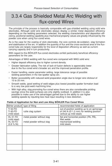
3-41
The principle of the process is basically comparable with gas-shielded welding using solid wireelectrodes. Although solid wire electrodes always display a similar metal deposition efficiencydepending on the welding parameters selected, the welding characteristics and deposition effi-ciency, positional welding capability plus mechanical property values are greatly influenced by thepowder core when using flux-cored wires.
As is the case for the coating of stick electrodes, the core controls de-oxidation, slag formationand stabilisation of the arc. In addition the quantity of flux and the cross-sectional area of the flux-cored tube are largely responsible for the level of deposition efficiency as well as current-carrying capacity and in turn productivity.
With regard to this BÖHLER flux-cored electrodes exhibit particularly beneficial efficiency parameters for the user.
Advantages of MAG welding with flux-cored wire compared with MAG solid wire:• Higher deposit efficiency due to higher current density.• Greater fabrication safety. The risk of lack-of-fusion defects is appreciably lower
due to the flux-cored wire’s broader arc and the improved penetration profile.
• Easier handling, easier parameter setting, large tolerance range of possible welding parameters in the low-spatter spray arc.
• Better accessibility with reduced weld preparation angle due to longer wire stickout of 15 to 25 mm.
• Smooth welds, good wetting of weld edges plus lowest possible spatter formation lead to a very low post-weld machining time.
• With high-alloy, slag-promoting flux-cored wires there are also considerable pickling savings since the weld surfaces are only slightly oxidised. In addition it is also possible to make use of the advantages gained due to the ability to use higher welding speeds by inputting less heat input resulting in less distortion.
Fields of Application for Non and Low Alloy BÖHLER Flux Cored Wires
3.3.4 Gas Shielded Metal Arc Welding withflux-cored Wires
Böhler product type of filling recommended fields of applicationTi 52-FD out-of-position welding up to an apmerageTi 60-FD rutile slag system of 240 A (Ø 1.2 mm) for welding position (mild steel) vertical up mild steelsHL 51-FD metal powder without slag flat and horizontal position (PA, PB), (mild steel) fillet weldsHL 53-FD metal powder without slag mechanised welding(0,9 % Ni) mild steels
Process-based Selection of Consumables
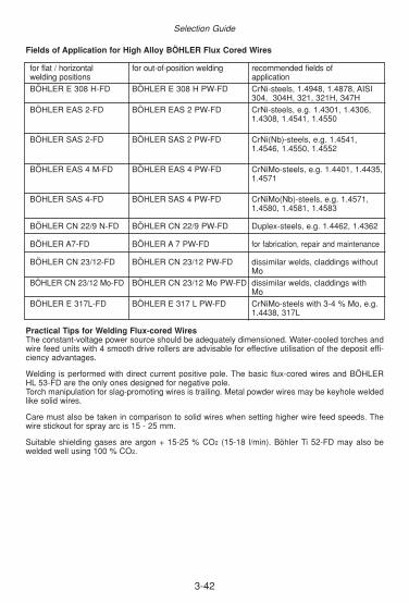
3-42
Fields of Application for High Alloy BÖHLER Flux Cored Wires
for flat / horizontal for out-of-position welding recommended fields of welding positions applicationBÖHLER E 308 H-FD BÖHLER E 308 H PW-FD CrNi-steels, 1.4948, 1.4878, AISI
304, 304H, 321, 321H, 347HBÖHLER EAS 2-FD BÖHLER EAS 2 PW-FD CrNi-steels, e.g. 1.4301, 1.4306,
1.4308, 1.4541, 1.4550
BÖHLER SAS 2-FD BÖHLER SAS 2 PW-FD CrNi(Nb)-steels, e.g. 1.4541, 1.4546, 1.4550, 1.4552
BÖHLER EAS 4 M-FD BÖHLER EAS 4 PW-FD CrNiMo-steels, e.g. 1.4401, 1.4435,1.4571
BÖHLER SAS 4-FD BÖHLER SAS 4 PW-FD CrNiMo(Nb)-steels, e.g. 1.4571, 1.4580, 1.4581, 1.4583
BÖHLER CN 22/9 N-FD BÖHLER CN 22/9 PW-FD Duplex-steels, e.g. 1.4462, 1.4362
BÖHLER A7-FD BÖHLER A 7 PW-FD for fabrication, repair and maintenance
BÖHLER CN 23/12-FD BÖHLER CN 23/12 PW-FD dissimilar welds, claddings without Mo
BÖHLER CN 23/12 Mo-FD BÖHLER CN 23/12 Mo PW-FD dissimilar welds, claddings with Mo
BÖHLER E 317L-FD BÖHLER E 317 L PW-FD CrNiMo-steels with 3-4 % Mo, e.g. 1.4438, 317L
Practical Tips for Welding Flux-cored WiresThe constant-voltage power source should be adequately dimensioned. Water-cooled torches andwire feed units with 4 smooth drive rollers are advisable for effective utilisation of the deposit effi-ciency advantages.
Welding is performed with direct current positive pole. The basic flux-cored wires and BÖHLERHL 53-FD are the only ones designed for negative pole.Torch manipulation for slag-promoting wires is trailing. Metal powder wires may be keyhole weldedlike solid wires.
Care must also be taken in comparison to solid wires when setting higher wire feed speeds. Thewire stickout for spray arc is 15 - 25 mm.
Suitable shielding gases are argon + 15-25 % CO2 (15-18 l/min). Böhler Ti 52-FD may also bewelded well using 100 % CO2.
Selection Guide

3-43
Submerged-arc welding requires a metallic filler metal (wire) and a non-metallic consumable, thewelding flux.
The welding flux has a very large effect on the welding result. It has a significant effect on weldappearance and slag detachability as a result of the melting characteristics and various physicalproperties such as viscosity, surface tension, density, thermal expansion and electrical conduc-tivity.
There is also a significant effect on the chemical composition of the weld metal and in turn on itsmechanical property values resulting from the metallurgical reaction of the welding flux.Depending on the type of manufacture it is possible to differentiate between:
Fused flux, code letter F (fused), e.g. BÖHLER BF 16. Manufactured by melting in the arc kiln; homogeneous, not susceptible to moisture, abrasion-proof, but very limited metallurgical reaction, high apparent density and poorer slag detachability.
Agglomerated flux, code letter A (agglomerated), e.g. BÖHLER BB 24. Manufactured by agglomeration and subsequent drying in the rotary kiln; very good metallurgical reaction, low apparent density, good slag detachability, possibility of addition by alloying but susceptible to moisture and abrasion.
The welding fluxes are divided into acid, neutral and basic according to the degree of basicity. Thedegree of basicity is calculated from
Basic constituents (CaO, CaF2, MgO, MnO)B=
Acid constituents (SiO2, TiO2, ZrO2)
If B is less than 1 one speaks of an acid welding flux (acid constituents predominate), with a valuebetween 1 and 1.2 it is a neutral welding flux, above this a basic welding flux, and above 2 a high-ly-basic welding flux.
According to the predominant main constituents they may be termed:
as manganese silicate types (MS), predominantly MnO and SiO2. as calcium silicate types (CS), predominantly CaO, MgO and SiO2. as aluminate-rutile types (AR), predominantly Al2O3 and TiO2. as aluminate-basic (AB), predominantly Al2O3, CaO and MgO and as fluoride-basic (FB) with the main constituents CaO, MgO, MnO and CaF2.
Each type of flux has different specific properties that must be taken into consideration when sel-ecting them for practical use.
3.3.5 Recommendations for Submerged Arc Welding using Solid Wires
Process-based Selection of Consumables

3-44
Selection Guide

3-45
OverviewThe most important problem in selecting filler metals is correctly assessing themetallurgical behaviour of the metals to be welded. The whole welding tech-nology, pre-heating and any post-weld heat treatments correspond with this.
This section attempts to discuss the most important welding-engineeringaspects of different types of material groups in brief individual chapters. As faras possible a broad outline of the required welding technology is provided.
The last chapter of this section deals with the much more complex problemssurrounding mixed-metal joints. Since a detailed treatment of this topic wouldtake up a whole book, this chapter only contains brief references as to howvarious combinations of typical groups of materials should be dealt with.
Content3.4.1 WELDABILITY OF STEELS . . . . . . . . . . . . . . . . . . . . . . . . . . . . . . . . . . . . . . . . .46
3.4.2 MILD STEELS . . . . . . . . . . . . . . . . . . . . . . . . . . . . . . . . . . . . . . . . . . . . . . . . . . .47
3.4.3 COATED PLATES . . . . . . . . . . . . . . . . . . . . . . . . . . . . . . . . . . . . . . . . . . . . . . . .49
3.4.4 REINFORCING STEELS . . . . . . . . . . . . . . . . . . . . . . . . . . . . . . . . . . . . . . . . . . .50
3.4.5 CASE-HARDENING AND NITRIDING STEELS . . . . . . . . . . . . . . . . . . . . . . . . .52
3.4.6 WELDING OF PIPELINES . . . . . . . . . . . . . . . . . . . . . . . . . . . . . . . . . . . . . . . . . .53
3.4.7 HIGH-STRENGTH FINE-GRAIN CONSTRUCTIONAL STEELS . . . . . . . . . . . . .56
3.4.8 CRYOGENIC STEELS . . . . . . . . . . . . . . . . . . . . . . . . . . . . . . . . . . . . . . . . . . . . .58
3.4.9 HIGH-TEMPERATURE STEELS . . . . . . . . . . . . . . . . . . . . . . . . . . . . . . . . . . . . .60
3.4.10 LOW-ALLOYED TEMPERED STEELS . . . . . . . . . . . . . . . . . . . . . . . . . . . . . . .63
3.4.11 COMPRESSED HYDROGEN-RESISTANT STEELS . . . . . . . . . . . . . . . . . . . .65
3.4.12 STAINLESS STEELS . . . . . . . . . . . . . . . . . . . . . . . . . . . . . . . . . . . . . . . . . . . . .66
3.4.13 MARTENSITIC CHROMIUM STEELS . . . . . . . . . . . . . . . . . . . . . . . . . . . . . . . .67
3.4.14 FERRITIC CHROMIUM STEELS . . . . . . . . . . . . . . . . . . . . . . . . . . . . . . . . . . . .69
3.4.15 SOFT-MARTENSITIC CHROMIUM NICKEL STEELS . . . . . . . . . . . . . . . . . . . .71
3.4.16 AUSTENITIC CR-NI(-MO)-STEELS . . . . . . . . . . . . . . . . . . . . . . . . . . . . . . . . . .73
3.4.17 FERRITE DETERMINATION IN WELD DEPOSIT . . . . . . . . . . . . . . . . . . . . . . .75
3.4.18 HEAT RESISTANT STEELS . . . . . . . . . . . . . . . . . . . . . . . . . . . . . . . . . . . . . . . .80
3.4.19 WELDING OF DISSIMILAR JOINTS . . . . . . . . . . . . . . . . . . . . . . . . . . . . . . . . .81
3.4. Material based Selection of Consumables
◆
◆
Material based Selection of Consumables

3-46
On one hand the weldability of steels depends essentially on their tendency to hardening and theformation of brittle microstructures in the transition zones of welds as well as on their ability toabsorb stresses on the other. Where steels with limited weldability are concerned, particularly thosesusceptible to stresses and/or a tendency to hardening, it is still possible in many cases to fabri-cate perfect welds by using an appropriate welding procedure (control of temperature, heat treat-ment).
Weldability of Mild SteelsWith regard to the content of phosphorus and sulphur, weldability of non-alloy steels will usually beclassified according to carbon content. Areas of the parent metal in the weld transition zones willbe austenitised as a result of the heat generated during welding. Localised increases in hardnessmay occur inside these heat-affected zones as a consequence of rapid cooling. Therefore as a ruleit is possible to weld non-alloy steels with carbon contents up to approx. 0.22 % without problems;with higher carbon contents it is necessary to preheat the parent metal or care must be taken toensure correct control of heat in the welded sections so as to reduce the cooling rate during aus-tenite transformation. However, it is not only carbon that determines the weldability of non-alloysteels. Problems during welding may also arise due to higher contents of hydrogen, nitrogen andoxygen and the presence of segregations. The wall thickness also plays an important role.
Weldability of Alloy Steels
Low-alloy SteelsLow-alloy steels often require proper control of heat prior to, during and after welding in order toachieve welds with the properties required. The chemical composition with regard to the type andquantity of alloying constituents and the microstructure has a significant effect. It is possible toimprove the strength and ductility of high-tensile low-alloy steels by quenching and tempering. Thetotal alloy content does not usually exceed 5 %. As a rule the carbon content lies between 0.2 and0.6 %. Important alloying elements are chrome, nickel and molybdenum, as well as manganese,silicon and vanadium.
Their inclination towards the formation of martensite leads to greater stresses inside the compo-nent on cooling of the weld. The critical cooling rate is low and therefore it is possible for a hardmicrostructure to occur even on cooling in ambient air thus unfavourably changing the ductility ofthe weld. There is a high risk of hardness cracks in transition zones. Areas of pronounced softeningmay appear in the case of steels with limited resistance to tempering.
High-alloy SteelsHigh-alloy steels contain over 5 % of alloying elements. Stainless steels containing chrome andthose containing both chrome and nickel as characteristic alloying elements represent a significantsection of these steels.
Chromium steels are mainly divided into two grades with a ferritic or martensitic microstructurewhich exhibits limited weldability. The reason for this is the tendency towards grain growth in ferri-tic chrome steels and a tendency towards hardness increase in the heat-affected zones of chrome-based martensitic steels.
By contrast the austenitic chromium-nickel (molybdenum) steels are classified as having goodweldability. However, the corrosion resistance, hot crack resistance and ductility of these steelsmay deteriorate if fabricated unprofessionally. Consequently it is necessary to observe certainbasic rules when welding stainless steels.
3.4.1 Weldability of Steels
Selection Guide

3-47
These steels which conform to EN 10025 (DIN 17100) are determined by components which willbe utilised essentially at ambient temperatures.
According to the regulations of EN 10027, Part 1 (Classification of Steels) the code letter
1. S - Steels for general steel construction, or2. E - Machine-construction Steels
is set in front of the abbreviated designation followed by a number which refers to the minimumyield strength in N/mm2 given the lowest thickness manufactured. The yield strength ranges lie bet-ween 185 and 355 N/mm2 (~27 and 51 ksi) for steels classified "S" and between 295 and 360N/mm2 (~43 and 52 ksi) for steels classified "E".
The ability to specify a specific maximum value of carbon equivalent (CET) on purchase ordersmay be considered an advantage from the weldability point of view. However, this applies only tosteel grades "S 235" to "S 355". All other steels of this standard exhibit limited qualifications for wel-ding. Steel grades such as these must be classified primarily as possessing "limited weldability",the fabrication process for which is left up to the manufacturer where the chemical composition isnot defined at all.
Welding of Mild SteelsThe weldability of steels diminishes as the carbon content rises due to the increase in hardness.Therefore steels with no guarantee of weldability must be treated specifically in order to avoid unac-ceptably high hardness. The ability to predict the tendency towards hardening, e.g. by calculationof the carbon equivalent, etc., is well known. As a rule of thumb it may be said that hardness increa-se in the transition zone should not exceed 350 Vickers units for non-alloy constructional steels and400 Vickers units for alloy constructional steels.
Welding Technology for Mild Steels
◆ Filler metals must be selected with respect to the minimum requirements for the mechanical properties of the parent metals.
◆ Steels with “guaranteed weldability“ and wall thicknesses exceeding 30 mm (13/16“) or20 mm (3/4“) must be preheated to 100 - 150 °C (210 - 300 °F) and basic-type filler
metals must be used.◆ Steels with “limited weldability“ must be preheated in accordance with the carbon equiva
lent; only rebaked basic filler metals are to be used.◆ For rimmed steels avoid melting of segregation zones as far as possible and use basic
filler metals as well.
Filler metalsThe following section lists examples of suitable filler metals.
base material (example) BÖHLER-product
S235J2G3 to S355J2G3FOX OHV, FOX ETI, FOX EV 50, EMK6, EMS2/BF16, HL 51-FD
Dependency of Welding Procedure on Material ThicknessIn addition, reference must be made to the fact that as the thickness of the component increasesthree-dimensional stresses caused by localised heating and cooling may reach the yield strengthor may even exceed it when superimposed with operating loads. These stresses then lead to colddeformation, ageing and embrittlement. Therefore even steels with guaranteed weldability requirepreheating above certain wall thicknesses.
Typical wall thicknesses for good weldability are:
3.4.2 Mild Steels
Material based Selection of Consumables

3-48
tensile strength [N/mm2] thickness limit [mm]up to 360 30
> 360 - 540 20
Larger wall thicknesses call for preheating to 100 - 150 °C (210 - 300 °F) in all cases.
Weldability of Rimmed SteelsAccording to EN 10025 and DIN 17100 respectively rimmed steels may also be welded. Thesesteels show a pure and ductile shell zone ("bacon rind") which causes no problems during weldingbut contains a core rich in segregation with poor weldability. The core often exhibits significantlyhigher contents of carbon, phosphorus, sulphur, oxygen and manganese than the shell zone dueto liquefaction phenomena on solidification (segregation in the ingot). One is confronted with anumber of negative influences in respect of the segregated zone, such as increased tendencytowards hardening, risk of brittle fracture, tendency to hot cracking and embrittlement by ageing.
Given these facts the segregated zone exhibits lower ductility and poor weldability compared withthe pure shell zone. The primary rule for welding rimmed steels is therefore not to fuse segregatedzones if possible, which is a point that should be taken into account at the design stage. Rimmedsteels with segregation will be welded in practice using basic-coated electrodes or using a combi-nation of rutile and basic-coated electrodes (basic coated electrodes for the segregated zone, ruti-le type electrodes for root and cap layer).
Free-cutting SteelsFree-cutting steels are characterised by good machinability and good chip brittleness that are essentially achieved by means of higher sulphur contents coupled in part with lead and other elements. They allow high edge lives of the cutting tools at high cutting speeds during cutting onautomatic high-speed machines and as a result produce finished parts with a very clean smoothsurface.
The microstructure of free-cutting steels differs from that of other steels only due to the sulphidicinclusions introduced on purpose.
Welding of Free-cutting SteelsSimilar considerations to those for the welding of unkilled steels apply to the welding of low-carb-on free-cutting steels and consequently welding is possible to a limited extent. On the other handthe welding of higher-carbon steels must be considered difficult. In this case the tendency towardshot cracking is extremely high due to the higher contents of carbon and sulphur. Particular attenti-on must be paid to poor penetration and stress-free welding.
The suitability of free-cutting steels for welding is very limited indeed. Free-cutting steels containinglead should not be welded due to the health hazards caused by leaded welding fume.
Selection Guide
3-49
Coating with Anti-corrosive PaintsStructures made of non-alloy steels may undergo substantial reductions in cross-section as a resultof rusting. Material loss such as this may be counteracted by painting with effective anti-corrosionpaint, which to some extent is carried out immediately after descaling (prefabrication priming) onhot-rolled products for economic reasons. Iron oxide-rich paints are most commonly used. Thisbrings to light the problems associated with the weldability of plates coated with such paints.
Iron oxide-rich paints are readily weldable with regard to the TLV (threshold limit values in theworkshop environment) and are not susceptible to porosity whereas zinc dust-rich paints maycause problems with the TLV as well as porosity. Butt welds are less prone to porosity than filletwelds. Whilst rutile coated electrodes such as BÖHLER FOX OHV will generally deposit welds freeof porosity, it is not always possible to guarantee this when using basic coated types. Wires withincreased silicon content and fluxes with high MnO contents should be used for submerged-arcwelding. Inert-gas welding using CO2 as the shielding gas often leads to problems; this can beimproved by adding a few percent of oxygen to the shielding gas.
Galvanised PlatesHot galvanizing offers very effective protection of the steel surface against corrosive media.
When welding galvanized plates and sheet metal there is intense generation of fume depending onthe type of electrode used due to the evaporation of zinc. Medium-thick rutile-coated electrodes,such as the FOX MSU type, may be used. These will not affect the mechanical properties. Fordouble fillet welds with wall thicknesses above 10 mm (3/8”) on all-round galvanized sheet metal itis necessary to maintain a gap of at least 1 mm (3/64”) between the flange and web to avoid zinc-induced cracking.
3.4.3 Coated Plates
Material based Selection of Consumables

3-50
Concrete, the traditional material used for building, possesses high compressive strength but onlylow tensile strength. This means that a fracture in the structure is highly likely after applying only arelatively low load if a structure made purely of concrete is loaded for bend.
Steel rods are inserted in the concrete to increase the tensile strength of this construction materi-al producing a composite structure which utilises both the excellent compressive strength of theconcrete and the high tensile strength of the steel.
The various types of reinforcing steels differ from each other either due to their external form (vary-ing surface shape) or processed form (e.g. as welded wire meshes) or both. The reinforcing steels,also known as armouring, are subdivided into the following types:
Rods of
1. hot-rolled round steel2. hot-rolled ribbed steel3. hot-rolled and then cold-twisted ribbed steel4. cold-formed ribbed steel
as well as welded reinforcing meshes of
5. flat wires6. shaped wires7. ribbed wires.
Welding of Reinforcing SteelsAll steels of the DIN 488 or EN 10080 referred to are suitable for resistance flash-butt welding andoxyacetylene pressure welding. Suitability for electric arc welding using coated stick electrodes orthe gas-shielded arc process is considered to have been demonstrated if the base metal ultimatestrength is achieved in the tensile test and it is possible to bend butt welds around a required mand-rel.
Welds may be classified according to their intended use or the welding process employed. Theprincipal distinction is between load-bearing and non-load-bearing welds.
Welding Technology
◆ The steel surface in the area of the weld must be cleaned of dirt, grease, rust, etc. and there must be adequate access to the welding area.
◆ The weld area must exhibit a temperature of at least +5 °C and must be protected against cooling down too quickly after welding to reduce the risk of hardness increase in the transitionzone.
Filler MetalsThe following overview shows suitable Böhler filler metals:
Reinforcing Steel grade BÖHLER-productDIN ENBSt 420 S B420N FOX SPE, FOX OHV, FOX MSU, EMK 6BSt 500 S B500H FOX SPE, FOX OHV, FOX MSU, EMK 6BSt 500 N B500N FOX EV 50, EMK 6
3.4.4 Reinforcing Steels
Selection Guide
3-51
Pre-stressed Reinforcing SteelsA high offset yield stress and apparent yield point plus high tensile strength are required of pre-stressed reinforcing steels to ensure there is little or no decrease in the pre-stressing of the concrete. Non-alloy C-Mn steel with 0.6 to 0.9 % C or steel similar to spring steel is used as a suitable material.
Welding of pre-stressed reinforcing steels is not permitted.
Material based Selection of Consumables

3-52
Case hardening is understood to be hardening following prior carburisation of the skin of a work-piece. Carburising and also nitrogenising in solid, liquid or gaseous media is performed at tempe-ratures between 850 - 930 °C following forming and machining after which hardening takes place.The carburised layer assumes a content of 0.7 to 1 % C and a surface hardness of 59 to 67 HRC.Case hardening is used where the aim is to achieve a hard surface resistant to wear and fatigue(higher fatigue strength), but where the transition and the low-lying core should have good ductili-ty and high notch impact strength with improved strength.
Nitration is understood to be the treatment of steel surfaces in media giving off nitrogen at tempe-ratures below the Ac1 point to achieve a surface enriched with nitrogen. Nitriding steels are steelsthat are particularly suitable for nitration due to the nitride formers contained within them.Chromium-containing steels that are alloyed with aluminium for increased special nitride formationare primarily considered as materials. To some extent they also exhibit molybdenum and nickel.The nitrided surface layers (approx 0.05 to 0.5 mm) are very hard even without quenching (approx.750 to 900 HV) and wear-resistant, i.e. they provide resistance to sliding abrasion that is better thanin case-hardened parts.
Welding of Case-hardened and Nitriding SteelsFor welds in the surface area of case-hardened or nitrided parts it is first necessary to remove a suf-ficiently large area of the carburised or nitrided layer by grinding. However, it seems advisable toweld prior to case hardening or nitration.
Filler metals similar in alloy composition to the parent metal must be used if the welds are also inten-ded to be nitridable. Otherwise filler metals corresponding to the mechanical properties of the parentmetal not subjected to surface treatment should be used. Basic electrodes are to be preferred.
The preheat temperature must be matched to the steel’s hardenability.
3.4.5 Case-hardening and Nitriding Steels
Selection Guide
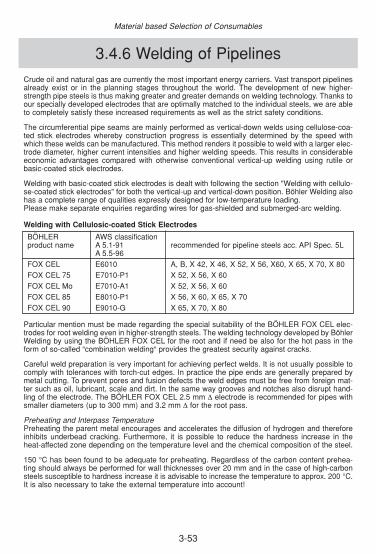
3-53
Crude oil and natural gas are currently the most important energy carriers. Vast transport pipelinesalready exist or in the planning stages throughout the world. The development of new higher-strength pipe steels is thus making greater and greater demands on welding technology. Thanks toour specially developed electrodes that are optimally matched to the individual steels, we are ableto completely satisfy these increased requirements as well as the strict safety conditions.
The circumferential pipe seams are mainly performed as vertical-down welds using cellulose-coa-ted stick electrodes whereby construction progress is essentially determined by the speed withwhich these welds can be manufactured. This method renders it possible to weld with a larger elec-trode diameter, higher current intensities and higher welding speeds. This results in considerableeconomic advantages compared with otherwise conventional vertical-up welding using rutile orbasic-coated stick electrodes.
Welding with basic-coated stick electrodes is dealt with following the section "Welding with cellulo-se-coated stick electrodes" for both the vertical-up and vertical-down position. Böhler Welding alsohas a complete range of qualities expressly designed for low-temperature loading.Please make separate enquiries regarding wires for gas-shielded and submerged-arc welding.
Welding with Cellulosic-coated Stick Electrodes
BÖHLER AWS classificationproduct name A 5.1-91 recommended for pipeline steels acc. API Spec. 5L
A 5.5-96FOX CEL E6010 A, B, X 42, X 46, X 52, X 56, X60, X 65, X 70, X 80FOX CEL 75 E7010-P1 X 52, X 56, X 60FOX CEL Mo E7010-A1 X 52, X 56, X 60FOX CEL 85 E8010-P1 X 56, X 60, X 65, X 70FOX CEL 90 E9010-G X 65, X 70, X 80
Particular mention must be made regarding the special suitability of the BÖHLER FOX CEL elec-trodes for root welding even in higher-strength steels. The welding technology developed by BöhlerWelding by using the BÖHLER FOX CEL for the root and if need be also for the hot pass in theform of so-called “combination welding“ provides the greatest security against cracks.
Careful weld preparation is very important for achieving perfect welds. It is not usually possible tocomply with tolerances with torch-cut edges. In practice the pipe ends are generally prepared bymetal cutting. To prevent pores and fusion defects the weld edges must be free from foreign mat-ter such as oil, lubricant, scale and dirt. In the same way grooves and notches also disrupt hand-ling of the electrode. The BÖHLER FOX CEL 2.5 mm ∆ electrode is recommended for pipes withsmaller diameters (up to 300 mm) and 3.2 mm ∆ for the root pass.
Preheating and Interpass TemperaturePreheating the parent metal encourages and accelerates the diffusion of hydrogen and thereforeinhibits underbead cracking. Furthermore, it is possible to reduce the hardness increase in theheat-affected zone depending on the temperature level and the chemical composition of the steel.
150 °C has been found to be adequate for preheating. Regardless of the carbon content prehea-ting should always be performed for wall thicknesses over 20 mm and in the case of high-carbonsteels susceptible to hardness increase it is advisable to increase the temperature to approx. 200 °C.It is also necessary to take the external temperature into account!
3.4.6 Welding of Pipelines
Material based Selection of Consumables

For thin pipe materials unsusceptible to hardening increase it is beneficial to heat the pipe endsslightly to at least 50 °C to remove condensation water. According to the various specifications dif-ferent carbon contents are permissible. If the carbon content is above 0.20 % we recommend con-sulting the electrode and steel manufacturer about the choice of preheat temperature.
The interpass temperature affects the metallurgical processes which take place during solidificati-on and cooling and thus has an effect on the mechanical properties of the weld metal. It also affec-ts the diffusion speed of hydrogen. It is therefore recommended that the interpass temperatureshould be maintained at no less than 80 °C during welding. An interpass temperature of at least140 °C is recommended if cellulose-coated stick electrodes with tensile strengths above 620N/mm2 (e.g. BÖHLER FOX CEL 90) are used.
Welding with Basic-coated Stick ElectrodesIn some countries the use of basic-coated stick electrodes for pipeline construction is preferredover the use of cellulose-coated stick electrodes for various reasons. Generally speaking the useof basic electrodes is recommended for welding very thick steels over 25 mm susceptible tohardness increase. The reason for this is the very low hydrogen content of these types of electro-des.
The high dissipation of welding heat in higher wall thicknesses and the simultaneous presence ofhigher hydrogen contents increases the risk of hydrogen-induced underbead cracks when usingcellulose-coated stick electrodes. To prevent this it is only worthwhile using basic-coated stick elec-trodes if the root pass is also welded using the same type of electrode.
In vertical-up welding using basic-coated stick electrodes the time required above all for root wel-ding is relatively high. Naturally this is also linked to a certain loss of economic viability. As a resultbasic-coated vertical-down electrodes have been developed which may be used for both root wel-ding and also filler and cover pass welding.
Vertical-up WeldingDepending on the pipe material’s chemical composition and its tendency towards hardness increa-se, preheating to 150 200 °C should be carried out for thick plates even when using basic-coatedstick electrodes.
The preference in this case is to use basic-coated electrodes of the FOX EV 50 (E7018-1), FOXEV 55 (E7018-1), FOX EV 60 (E8018-G) and above all the FOX EV PIPE (E7016) type special-ly optimised for pipe welding. Care must be taken to protect the electrodes against moisture.Electrodes from boxes that are already open must be re-dried before use for 2 hours at 300 – 350 °Caccording to the specifications.
The root pass is usually applied using electrodes with a 2.5 mm ∆ in order to achieve perfect root fusion. Welding is performed in the vertical-up position with a root gap of approx. 2.5 - 3 mm. At times a special weld shape is used tosave weld metal (see sketch).
Welding of the filler and cover passes is usually performed using electrodes with 3.2 und 4 mm ∆ whereby the welding area must be protected against wind, rain, etc. to prevent pores.
Vertical-down Welding
BÖHLER AWS-classification recommended for pipeline steelsproduct name A 5.5-96 acc. API Spec. 5LFOX BVD RP E8018-G A, B, X 42 - X 100FOX BVD 85 E8018-G A, B, X 42 - X 65FOX BVD 90 E9018-G X 70, X 80FOX BVD 100 E10018-G X 80FOX BVD 110 E11018-G X 100FOX BVD 120 E12018-G X 110
3-54
Selection Guide

3-55
Executing the Welding of PipelinesWeld preparation: Weld preparation is carried out by metal cutting. The permissible dimensional
tolerances of the pipes are listed in the standards API Spec. 5 LX and DIN 17122.
Preheating: The risk of underbead cracks due to hydrogen when welding with basic-coated stick electrodes is lower than when welding with cellulose-coated stick electrodes due to theirrelatively low hydrogen content. Nevertheless preheating to 150 °C is recommended above all when welding thick-walled pipe materials that are susceptible to hardness increase. The following diagram illustrates when preheating is recommended.
Alignment of pipes: Alignment of the pipes is performed with hydraulically operated internal alignment clamps as when welding with cellulose-coated stick electrodes. Due to the relatively strong root bead formation and the low hydrogen content on the part of the basic-coated root electrode it is possible to release the internal alignment clamp when the rootweld is complete as long as the edge misalignment is not too great.
Welding at Low External Temperatures or in Wet WeatherUnder unfavourable weather conditions especially at air temperatures below 0 °C, welding workmay only be carried out on pipelines if the welding and working conditions render perfect weld exe-cution possible. This means that although welding at low external temperatures is not prohibited, itis necessary to observe certain safety precautions.
The following rules have been tried and tested in practical use:
1. Remove ice, frost and rain by warming up (preheat to hand-hot).2. Speedy welding without longish pause; if necessary employ several welders for one weld
seam.3. Use electrodes as thick as possible.4. The welder himself must be adequately protected against the cold (provide tents, windbreak or
infrared radiator).
There are no generally applicable rules or restrictive specifications regarding the execution of wel-ding work whilst raining or on wet workpieces. Nevertheless it is obvious that the welding area andits surroundings must be shielded from rain and other weather effects. The welding area must befree from water in all cases.
Rebaked basic stick electrodes have very little hydrogen in the weld metal from the start and the-refore provide a higher level of safety against hydrogen-induced cracks under unfavourable condi-tions. However, even the basic weld metal may exhibit substantial hydrogen contents during wel-ding in a steam-saturated atmosphere.
Material based Selection of Consumables
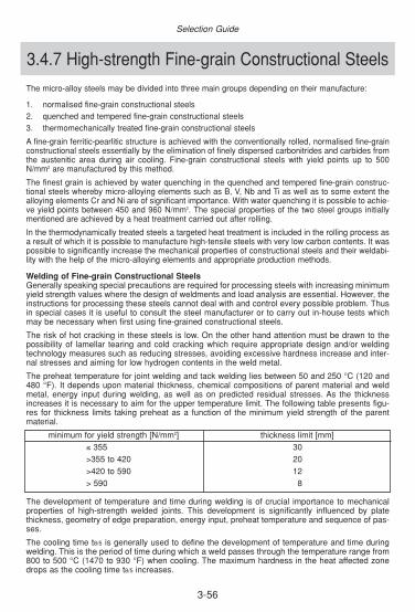
3-56
3.4.7 High-strength Fine-grain Constructional Steels
Selection Guide
The micro-alloy steels may be divided into three main groups depending on their manufacture:
1. normalised fine-grain constructional steels2. quenched and tempered fine-grain constructional steels3. thermomechanically treated fine-grain constructional steels
A fine-grain ferritic-pearlitic structure is achieved with the conventionally rolled, normalised fine-grainconstructional steels essentially by the elimination of finely dispersed carbonitrides and carbides fromthe austenitic area during air cooling. Fine-grain constructional steels with yield points up to 500N/mm2 are manufactured by this method.
The finest grain is achieved by water quenching in the quenched and tempered fine-grain construc-tional steels whereby micro-alloying elements such as B, V, Nb and Ti as well as to some extent thealloying elements Cr and Ni are of significant importance. With water quenching it is possible to achie-ve yield points between 450 and 960 N/mm2. The special properties of the two steel groups initiallymentioned are achieved by a heat treatment carried out after rolling.
In the thermodynamically treated steels a targeted heat treatment is included in the rolling process asa result of which it is possible to manufacture high-tensile steels with very low carbon contents. It waspossible to significantly increase the mechanical properties of constructional steels and their weldabi-lity with the help of the micro-alloying elements and appropriate production methods.
Welding of Fine-grain Constructional SteelsGenerally speaking special precautions are required for processing steels with increasing minimumyield strength values where the design of weldments and load analysis are essential. However, theinstructions for processing these steels cannot deal with and control every possible problem. Thusin special cases it is useful to consult the steel manufacturer or to carry out in-house tests whichmay be necessary when first using fine-grained constructional steels.
The risk of hot cracking in these steels is low. On the other hand attention must be drawn to thepossibility of lamellar tearing and cold cracking which require appropriate design and/or weldingtechnology measures such as reducing stresses, avoiding excessive hardness increase and inter-nal stresses and aiming for low hydrogen contents in the weld metal.
The preheat temperature for joint welding and tack welding lies between 50 and 250 °C (120 and480 °F). It depends upon material thickness, chemical compositions of parent material and weldmetal, energy input during welding, as well as on predicted residual stresses. As the thicknessincreases it is necessary to aim for the upper temperature limit. The following table presents figu-res for thickness limits taking preheat as a function of the minimum yield strength of the parentmaterial.
minimum for yield strength [N/mm2] thickness limit [mm]≤ 355 30>355 to 420 20>420 to 590 12> 590 8
The development of temperature and time during welding is of crucial importance to mechanicalproperties of high-strength welded joints. This development is significantly influenced by platethickness, geometry of edge preparation, energy input, preheat temperature and sequence of pas-ses.
The cooling time t8/5 is generally used to define the development of temperature and time duringwelding. This is the period of time during which a weld passes through the temperature range from800 to 500 °C (1470 to 930 °F) when cooling. The maximum hardness in the heat affected zonedrops as the cooling time t8/5 increases.

3-57
If a specific maximum hardness may not be exceeded in a particular steel then it is necessary toset the welding parameters in such a manner that the cooling time t8/5 does not fall below a defi-ned value. On the other hand increasing values for the cooling time t8/5 cause a reduction in theimpact strength and an increase in the transition temperature of impact strength within the heataffected zone.
If it is necessary to meet a specific minimum impact strength for a particular steel, then the weldingparameters must be set in such a way that the cooling time t8/5 is kept below a defined value. Thecooling time t8/5 to be applied in a particular case depends on the collective requirements formechanical properties including characteristic strength values of the actual weld joint in the post-weld heat-treated condition.
Selection of a suitable filler metal is of prime importance before welding a specific fine-grained con-structional steel. In this case allowance must be made for the fact that the weld metal must meetthe mechanical and technological properties of the base metal despite dilution.
Welding Procedure
◆ When selecting filler metals the weld metal must satisfy the mechanical properties of the base metal despite dilution by the latter. Use only re-dried basic-coated electrodes.
◆ Preheat and interpass temperature should be between 80 and 250 °C (180 and 480 °F) depending on wall thickness, chemical compositions of base metal and weld metal, energy input and existing state of residual stresses.
◆ Thickness limits must be considered when determining preheating as a function of the basemetal’s yield strength. Aim for the upper limit of the temperature range as wall thickness increases.
◆ The temperature/time curve (t8/5) is very significant for the mechanical properties of heat-affected zones. Comply with the recommendations of steel manufacturers regarding energyinput at all times.
Filler metalsThe following table shows suitable BÖHLER consumables.
base material BÖHLER-product(example)S355NL FOX EV 50, EMK 6, EMS 2//BB 25 resp. BB 24S500QL FOX EV 65, NiMo 1-IG, 3 NiMo 1-UP//BB 24S690QL FOX EV 85, X70-IG, 3 NiCrMo 2.5-UP//BB 24
Material based Selection of Consumables
3-58
The large-scale use of oxygen in the steel industry, nitrogen in the chemical industry and naturalpetroleum gases in industrial supply and also in the chemical industry has increased significantlyin recent years. With the increase in the use of these gases transporting and storing them econo-mically has become more and more important. The gases pass over into the liquid state when coo-led to very low temperatures and at the same time their volume decreases considerably. This beha-viour is utilised for storage and transport.
However, it is only possible to utilise this behaviour if suitable base metals and filler metals, whichposses adequate mechanical properties and toughness at the low temperatures of the liquid gases,are available for construction of the transport and storage tanks required.
Non-alloy, low-alloy or high-alloy steels that are still tough at low temperatures (below approx -50 °C)are known as cryogenic steels. Non-alloy and low-alloy steels may be used in all cases for tempe-ratures up to -50 °C as long as they are killed.
The steel groups may be differentiated as follows:
1. Non-alloy and low-alloy cryogenic and fine-grain constructional steels for operating temperatures up to approx. -50 °C in the normalised condition and down to approx. -60 °C in the quenched and tempered condition.
2. Nickel-alloy tempering steels with 1.5 to 9 % nickel for operating temperatures from -80 °C to approx. 200 °C.
3. Austenitic chrome nickel steels for operating temperatures down to approx. -269 °C.
Welding of Cryogenic SteelsThe characteristic properties of filler metals for welding cryogenic materials is their deformability atlow temperatures which is tested as a rule using the notched bar impact test. Conclusions regar-ding the propensity to brittle fracture and employability down to a specific temperature are drawnfrom the impact energy value. The notch shape of the notched bar test specimens is a noteworthyinfluential variable on the test results. U-notch specimens according to DVM result in higher impactenergy and lower service temperatures than the V-notch specimens according to ISO, more com-monly known as Charpy-V-notch specimens.
The value 27 is frequently taken as the minimum value of impact energy with the Charpy-V-notchspecimen at the lowest service temperature in each case.
Care must be taken to control the heat input when welding cryogenic and fine-grain constructionalsteels to keep the heat affected zone as narrow as possible and still prevent hardness peaks.Basic-coated non-alloy and low-alloy stick electrodes according to EN 499 and EN 757 are suita-ble. The hydrogen content in the welded joint should be as low as possible to prevent cold cracks,i.e. rebaking of the electrodes immediately prior to welding is recommended. This statement alsoapplies to the flux powder in submerged-arc welding. The problem of excessively high hydrogencontents does not normally exist for gas-shielded arc welding. Particular attention should be paidto the low-temperature toughness and strength required when selecting wire and flux combinationsor wire and shielding gas combinations.
Filler metals of the same or similar composition as the parent metal with 2.0 to 3.5 % Ni are usedwhen welding nickel-alloy tempering steels. Filler metals of the same composition as the parentmetal are to be preferred if it is necessary to guarantee the mechanical and technological (strength,toughness) and physical (heat expansion coefficient) properties of the parent metal in the weld metalin addition to satisfying the minimum temperature required.
3.4.8. Cryogenic Steels
Selection Guide

3-59
Filler metals with higher nickel contents have a tendency towards increased hot cracking. For thisreason the 5 % nickel steel is preferably welded with austenitic filler metals on the basis of “A7” or“ASN 5“ and nickel-base types. Heat treatment of the weld must not take place out of regard forthe austenitic weld metal (embrittlement, carbon diffusion).
9 % Ni-steel is mainly joined using completely austenitic filler metals with a high nickel content ofthe “NIBAS 625“ type, or „FOX NIBAS 60/15“. This nickel-based type has advantages overconventional austenites due to a higher yield point and the possibility of heat treating welds. It mayalso be used for steels with a low nickel content. Crack resistance and adequate cold toughnessdown to -200 °C are ensured if dilution with the parent metal is limited.
Austenitic chrome nickel steels are welded in the same manner. The unstabilised weld metal isslightly superior to the stabilised weld metal in impact energy at low temperatures.
Material based Selection of Consumables

3-60
The mechanical strength properties of the non-alloy constructional steels undergo a significantreduction at increased operating temperatures; therefore, they are only suitable for use up to athreshold temperature of 350 °C. Under stress creep and flow processes occur in the steel atincreased temperatures as a result of which the permissible load becomes time dependent. Thusall calculation values for strength now have a time added to them from which it can be seen howlong the material can bear a specific stress up to fracture or up to a specific permanent elongation.In this context one talks about the creep rupture strength or creep strain limit.
Thus first and foremost high temperature steels have adequate mechanical strength at high ope-rating temperatures. In addition to this they must also exhibit a certain resistance to corrosion andin the event of hot aggressive gases increased scale resistance as well which is only achievablewith high-alloy steels. With the addition of specific alloying elements such as Cr, Mo, V, W, Ti andNb it is possible to increase the high-temperature strength properties and the creep resistance. Theslip planes are blocked due to the formation of special carbides and special nitrides (anti-slipeffect).
For a temperature load up to 550 °C small additions of Mo, V, and Cr are sufficient although Mohas the greatest effect on increasing the high-temperature strength. Above 550 °C increased scaleresistance is also required. In this case the 9 to 12 % Cr-steels with additions of Mo, V and Nb areconsidered. Above 600 °C the behaviour under long period stressing drops off so much in heat trea-table steels that special Cr-Ni steels (basic type: 16 % Cr, 13 % Ni) have to be used. The creepresistant steels are standardised in EN 10028, EN 10222-2, DIN 17155, DIN 17175 and DIN 17460.
Welding of High Temperature SteelsCreep-resistant steels may be divided into three main groups:
Ferritic-Pearlitic Steels(e.g. P295GH, P355GH and 16Mo3)
These are normalised steels. Basically these steels are not susceptible to hardness increase in theheat-affected zone. However above a certain wall thickness preheating to 150 °C is advisable(P295GH = 25 mm; 16Mo3 = 10mm.)
Bainitic (Martensitic) Ferritic Steels(e.g. 13CrMo4-5, 10CrMo9-10, 14MoV6-3).
These steels are quenched and tempered and air-hardening and special account must be taken ofthis when welding. Hard and brittle zones may develop simultaneously, both in the heat affectedzones (HAZ) and the weld metal itself, due to the formation of martensite which contributes towardsthe danger of underbead cracking. Stress cracking after completion of welding is also possible.
Therefore, depending on the steel grade it is advisable to carry out preheating to 100 - 300 °C priorto welding and a specific interpass temperature must be controlled. As the preheat and interpasstemperature is lower than the Ms temperature (Ms = 480 °C), annealing and tempering at 640 - 740 °Cbut below Ac3 in any case is necessary after welding is complete.
Consequently the temperature should not significantly exceed approx. 450 °C and the energy inputmust be limited to 7 - 24 kJ/cm. At a preheat temperature not exceeding 300 °C it is not complete-ly possible to prevent the formation of martensite (Ms = 480 °C) in the heat affected zone but itsformation will be minimized to approx. 30 - 50 %. Therefore, depending on the type of steel, it isnecessary to perform annealing and stress-relieving at 640 - 740 °C after welding is complete.
3.4.9. High-temperature Steels
Selection Guide

3-61
Martensitic Steels – Alloying Type 12 % Chromium(e.g. 12 %Cr-Stähle X20CrMo12-1. X22CrMoV12-1 und X22CrMoWV12-1).
These steels are also quenched and tempered. The predominantly martensitic structure calls for avery special heat control procedure during welding. Two different technological procedures areused which are known in practice by the terms "martensitic and austenitic welding techniques".
The difference between these methods is determined by preheat and interpass temperaturesabove Ms-temperature (400 - 450 °C) in "austenitic" welding and below Ms-temperature (200 - 250 °C) in "martensitic" mode. After completion of welding, cooling is carried out to 120 - 80 °C tocomplete the martensite transformation, followed by final annealing in the temperature range bet-ween 720 - 780 °C.
Martensitic Steels – Alloying Type 9 % Chromium(e.g. 10CrMoVNb9-1, X12CrMoWNiVNbN10-11 and E911/NF 616).
There has been another material available since the beginning of the 80’s that guarantees outs-tanding high-temperature strength properties due to its modified alloy base. This material is thegrade P91 steel standardised to ASTM A335. Furthermore, there are efforts underway to find suc-cessor generations for the P91 materials. These cognate but as yet not standardised materials (NF616, P911 und HCM12) are supposed primarily to guarantee appreciably higher long-term creepstrength values resulting from the addition of tungsten by alloying.
Unlike the 12 % chrome types, the 9 % chrome types exhibit a lower tendency towards hardnessincrease during welding due primarily to the lower carbon content which results in a reduced riskof cold crack formation and the occurrence of stress corrosion cracking. However, a preheat andinterpass temperature ranging between 200 to 300 °C must be taken into account.
The use of the multi-pass technique is recommended since the welding technology has a consi-derable effect on the toughness properties achievable, i.e. thinner passes, in order to obtain a highproportion of annealed weld metal structure and thus an improved level of toughness.
Interim cooling to ambient temperature is necessary prior to the required postweld tempering (740-775 °C) to achieve complete martensitic transformation.
Choice of Filler MetalEssentially the filler metals used are those of the same composition as the base. Only under thiscondition is it possible to expect a creep rupture strength from the weld that corresponds to thebase metal. In the case of stick electrodes there are basic and rutile coated types available alt-hough the latter are only used for steels not exceeding 5 % Cr and up to 12 mm wall thickness dueto poorer mechanical properties and the higher hydrogen content. Rutile-coated stick electrodesare used mainly for root welding.
GTA welding is widely used for the root pass in pipes whilst the GMAW and submerged-arc pro-cesses are increasingly gaining in importance. The use of gas fusion welding is restricted to thin-walled joints in steels not exceeding 2.5 % Cr.
Welding Technology
◆ Use only filler metals with the same alloy composition as the base metal.◆ Above certain wall thicknesses normalised steels such as 16Mo3 must be preheated
to 150 °C.◆ Tempered steels such as 13CrMo4-5 must be preheated to 100 to 300 °C depending on type
and must be postweld annealed in the range between 640 and 740 °C.◆ With martensitic Cr steels on the basis of X20CrMoV12-1 care must be taken to ensure
special heat input, i.e. preheating to 200-250 °C or 400-450 °C, then cooling down to 80-120 °C and finally annealing at 720 to 780 °C.
◆ Martensitic Cr steels on the basis of 10CrMo9-10 must be preheated to 200 to 300 °C and may be cooled down to ambient temperature following welding. Then tempering treatment must be carried out at 750 °C.
Material based Selection of Consumables

3-62
Selection Guide
Filler MetalsThe following table provides examples of different BÖHLER filler metals for welding high tempera-ture steels:
base material BÖHLER product
16Mo3 FOX DMO Kb, DMO-IG, EMS 2 Mo/BB24,DMO Kb-FD, DMO Ti-FD
13CrMo4-5 FOX DCMS Kb, DCMS-IG, EMS 2 CrMo/BB 24,
10CrMo9-10 FOX CM 2-Kb, CM 2-IG, CM 2-UP/BB 24
X10CrMoVNb9-1 FOX C 9 MV, C 9 MV-IG, C 9 MV-MC, C 9 MV-UP/BB 910
X12CrMoWVNbN10-1-1 FOX C 9 MVW, C 9 MVW-IG, C 9 MVW-UP/BB 910
P 92, NF 616 FOX P 92, P 92-IG, P 92-UP/BB 910
X20CrMoWV12-1 FOX 20 MVW, 20 MVW-IG, 20 MVW-UP/BB 24

3-63
These steels are mainly used in the construction of machinery and equipment, in boilers, in the con-struction of piping and chemical plants, in the petrochemical industry, in cryogenics and in the auto-mobile and aircraft industry. They are used in the quenched and tempered condition, as a result ofwhich constructional steels such as this are termed tempering steels. Their special property is har-denability which depends principally on the type and proportions of the alloying elements they con-tain.
Due to a special alloying technique the critical cooling speed is reduced increasing in turn the tem-perability and creep resistance. Depending on the alloy composition it is possible to differentiatebetween Mn, Mn-Si, Mn-V steels; Cr, Cr-Mo, Cr-Mo-V, Cr-Ni-Mo steels; Ni, Ni-Cr steels and others.
Targeted lowering of the critical cooling speed for the purpose of good temperability worsens thesteel’s weldability. Structural components between bainite and martensite occur in the heat affec-ted zone of the base metal which cause local hardness increases. The higher the carbon contentin the steel, the harder the martensite becomes and the lower the martensite formation temperatu-re lies (Ms).
Knowing the martensite formation temperature is of major significance for determining the preheattemperature of steels with poor weldability. In addition to the familiar methods of determining thepreheat temperature such as the carbon equivalent, TTT curve, weld TTT curve and hardnesstesting of practical welds, it is also possible to calculate the Ms or Mf point according to the follo-wing formula:
Ms point (start of martensite formation): Ms(°C)=561-474(% C)-33(% Mn)-17(% Ni)-17(% Cr)-21(% Mo).
Mf-point (end of martensite formation): Mf (°C) = Ms-215±15
The two formulae are applicable for steels with approximately the following chemical composition:
% C % Si % Mn % Ni % Cr % Mo0.1 - 0.55 0.1 - 0.35 0.2 - 1.7 0 - 5 0 - 3.5 0 - 1
The following table shows the hardness, tensile strength and notch impact energy of the martensi-te in alloy steels with varying carbon contents (following heating to 200 °C according toThorneycroft).
carbon tensile strength impact work hardness[%] [N/mm2] [J] [HV 10]0.14 1370 85 4200.20 1480 60 4400.26 1650 41 4700.40 1860 24 5600.61 2200*) 7 700
*) brittle crack
Alloying elements such as manganese, nickel, chrome and molybdenum promote the γ-α transfor-mation in the martensitic stage. As a result low-alloy steels have a greater tendency towardshardness increase than non-alloy steels with the same carbon content.
3.4.10 Low-alloyed Tempered Steels
Material based Selection of Consumables

3-64
Welding of Low-alloy Tempering SteelsIt is hardly possible to find a filler metal of the same composition as the base for welding a speci-fic tempering steel that usually contains above 0.25 % C. Nor is this sensible because for weldingengineering reasons the carbon content in the weld metal is reduced and attempts are made toachieve the desired strength and tempering qualities by means of a suitable combination of alloys.However, in many cases it is not expected that the weld will achieve the strength of the base metalor it is not designed with high load ranges in mind. The filler metals then used are non-alloy basicelectrodes or austenitic electrodes. In both cases the high weld metal ductility has a favourableeffect with regard to at least a partial reduction of stress.
Filler metals for joint welding of tempering steels have not been standardised as yet.
Welding Technology
Proceed as follows to prevent cracks in the weld interfaces:1. Use non-alloy or low-alloy electrodes with low hydrogen content which are adequately re-dried
prior to welding. In certain cases austenitic electrodes may also be used. Gas metal-arc welding using argon or mixed gases may also be used.
2. Preheat to prevent or delay martensite formation. The possibilities for determining the preheattemperature have already been outlined.
3. Weld with thick electrodes and high heat input per unit length of weld. As a result cooling progresses more slowly.
Postweld heat treatment at approx. 600 °C and above, preferably without interim cooling, is recom-mended to reduce the residual welding stresses and to temper the hardened zone if there is a fearof cracking, especially in air-hardening steels.
Consideration should also be given to isothermic welding, i.e. maintaining the interpass tempera-ture up to the formation of harmless structures.
Austenitic filler metals of the "A 7" type (18 % Cr, 8 % Ni, 6 % Mn alloy type), whose weld metalcannot of course be tempered, are often chosen for air-hardening steels (e.g. armoured steel withhigher carbon content of the 30 CrNiMo 8 type). They are particularly suitable because the low yieldpoint and high plastic ductility of the alloy make it possible to reduce stress peaks by means oflower deformation without the danger of cracking.
Selection Guide

3-65
Steels that are only slightly susceptible to decarburisation by hydrogen at high pressures and hightemperatures and to the embrittlement and intercrystalline failure associated with this are conside-red to be compressed hydrogen-resistant steels. These properties are achieved by alloying withelements that form highly resistant, barely decomposable carbides at the operating temperature.Chrome is one such element. The following for example are compressed hydrogen-resistant steels25CrMo4, 20CrMo9, 17CrMoV10, X20CrMoV121, X8CrNiMoVNb1613 in accordance withSteelMaterial Specification 590.
At high pressures hydrogen penetrates the steel and reacts with the carbon in the iron carbide orpearlite forming methane at the same time. High pressures which lead to disaggregation and final-ly to intercrystalline cracks occur inside the steel since the methane molecules have only a very lowdiffusability due to their size.
Welding of Compressed Hydrogen-resistant SteelsCompressed hydrogen-resistant steels are weldable if the necessary precautions are taken.However, their weldability declines as the carbon content increases. These steels must be prehea-ted to 200 to 400 °C depending on the type of steel and this temperature must be maintained duringwelding.
After welding cooling must be slow and even. Postweld heat treatment must be carried out as spe-cified. The filler metals must also result in a compressed hydrogen-resistant weld metal. SteelsX20CrMoV12-1 and X8CrNiMoVNb16-13 require a very specialised welding technology.
3.4.11 Compressed Hydrogen-resistant Steels
Material based Selection of Consumables

3-66
The group of stainless steels contains a large number of very different alloy variations all of whichare commonly characterised by a chrome content of at least 12 %. This guarantees that extreme-ly thin, stable oxide layers form on the surface of the steel under oxidising conditions and the steelpasses from the active (soluble) to the passive (insoluble) condition. In the passive condition thereis increased resistance to oxidising media. However, in the case of a reducing atmosphere, i.e.decreased oxygen supply, the formerly passive steel may pass over into the active condition. Thechrome content of at least 12 % necessary for a certain chemical resistance of the steel is veryoften referred to as the “parting limit”.
The alloying element chrome and subsequently nickel represent the basic elements for stainlesssteels. However, their effect with regard to the crystalline structure in the steel is very varied.With increasing nickel content the gamma area is extended whilst with increasing chrome contentthe gamma area is confined and above approximately 12 % only ferrite (= body-centred cubicmixed crystal) continues to prevail. Above a certain nickel content the microstructure is made uponly of austenite (= face-centred cubic mixed crystal) from solidification to ambient temperature.
All other alloying elements which are added to the steel to improve specific properties may beassigned to either the chrome or nickel in their effect on the crystalline structure. This means thatit is possible to differentiate as follows between ferrite-forming and austenite-forming elements.Ferrite-forming elements: chrome, silicon, aluminium, molybdenum, niobium, titanium, tungstenand vanadium.
Austenite-forming elements: nickel, manganese, carbon, cobalt, copper and nitrogen.
If one adds sufficient quantities of nickel to a ferritic iron-chrome alloy then it passes over into theaustenitic condition.
The following table lists the most important groups of stainless steels classified according to themicrostructure.
micro structure typical steelpearlitic-martensitic X30Cr13half ferritic-ferritic X8Cr17soft-martensitic X5CrNi13-4ferritic-austenitic X2CrNiMoN22-5austenitic austenite with ferrite X5CrNi18-9
austenite without ferrite X8CrNiNb16-13
These groups of steels differ from each other from both the metallurgical and physical point of viewand allowance must be made for the peculiarities in each case by taking appropriate measureswhen fabricating welds.
3.4.12 Stainless Steels
Selection Guide

3-67
Some characteristic martensitic Cr steels and their weldabilty:
material designation % C % Cr % Mo weldabilityaccording EN 10088-1X12Cr13 0.15 13.0 - limitedX20Cr13 0.20 13.0 - strongly limitedX39CrMo17-1 0.42 16.5 1.2 none
Basically speaking this group of steels must be classified as having only limited weldability sincethe risk of cold cracking increases as the carbon content rises and joint welds should be avoidedwhere possible.
As already mentioned, the most important alloying element is chrome which lends the steels itspassivity and thus its corrosion resistance in oxidising media if it accounts for approximately 12 %of the content. Chrome as a ferrite-forming element has the effect of narrowing the iron’s austeni-tic zone and this is constricted completely with approx. 13 % chrome. Steels with chrome contentshigher than 13 % with very low carbon contents (< 0.1 %) undergo no transformation during coo-ling from solidification to ambient temperature. These are the ferritic chrome steels.
The group of hardenable steels starts with chrome contents above 12 % and carbon contents ofapprox. 0.1 to 1.2 %. These are the martensitic chrome steels. The austenitic zone is widened bythe higher carbon content creating the opportunity for hardening.
Welding of Martensitic Chromium SteelsThe austenitic fraction in the heat affected zone of the base metal will always transform into mar-tensite during air cooling as the formation of pearlite and bainite progresses with a significant timedelay due to the high chrome content.
Due to the steel’s high chrome content the beginning of pearlite transformation, during which δ fer-rite and carbide are precipitated out of the ?-mixed crystals, takes a long time so that the weld metaland the heat-affected zone (HAZ) practically always transform to the martensitic stage unless themartensitic transformation temperature is exceeded on heating. The unfavourable and inadequateweldability of such steels is easy to understand if one looks at the hardness increment as a func-tion of the carbon content.
Hardness increment with different carbon contents:
carbon content hardness0.10 % C app. 40 HRC0.15 % C app. 46 HRC0.20 % C app. 50 HRC0.25 % C app. 53 HRC0.40 % C app. 56 HRC0.70 % C app. 58 HRC1.00 % C app. 60 HRC
At the same time it becomes understandable why only martensitic Cr steels with less than 0.15 %carbon are usually used in practice for welded structures.
Hydrogen also represents a further unfavourable factor when welding. Somewhat higher hydrogencontents may cause a strong tendency towards hydrogen-induced cold cracks in the weld particu-larly in the presence of brittle martensite.
3.4.13 Martensitic Chromium Steels
Material based Selection of Consumables
3-68
13 % Cr steels are always tempered and 17 % Cr steels are always tempered or soft-annealedsince the martensite is relatively hard, brittle and at the same time susceptible to corrosion.
This group of steels is welded using filler metals of both the same and different composition to thebase. Please consult later sections for recommendations regarding the appropriate welding tech-nology and filler metals. The weld metal in the welded condition consists of martensite and δ-ferri-te with small proportions of residual austenite when using filler metals of the same or similar com-position to the base. For this reason only very low elongation and impact energy values are pre-sent and annealing is almost always carried out at 700 to 750 °C.
Welding Technology
for steels with carbon contents below 0.15 %
◆ Coated stick electrodes and submerged arc flux powders must be re-dried in accordance with the manufacturer’s instructions.
◆ Only use filler metals of the same composition as the base if there are requirements for the same colour, comparable strength or alternating strength. Otherwise use austenitic filler metals.
◆ A preheat and interpass temperature of 200 - 300 °C is to be recommended in any case.◆ Carry out postweld tempering at 700 - 750 °C. Beware when using austenitic filler metals
due to the risk of embrittlement.
Suitable BÖHLER filler metals are:
microstructure BÖHLER productequal FOX KW 10, FOX SKWAM, SKWAM-IGdifferent FOX A7 (IG/UP/FD), FOX EAS 2 (IG/UP/FD), FOX CN23/12 (IG/UP/FD)
Selection Guide

3-69
The following table contains the chemical composition and weldability of some ferritic Cr steelswhose characteristic feature is a low carbon content. As a result these steels are predominantly fer-ritic from the commencement of solidification to ambient temperature, and thus in the main are notsubject to transformation and are therefore also not hardenable. Mo, Ti or Nb are sometimes addedas alloying elements to improve the chemical properties.
material designation % C % Cr % Mo weldabilityaccording EN 10088-1X6Cr13 <0.08 13.0 - limitedX6Cr17 <0.08 17.0 - limitedX6CrMo17-1 <0.08 17.0 1.1 limited
The prerequisite for adequate technological values, particularly regarding elongation, is a fine-grainstructure. This is achieved if the final forming stages are carried out below 800 °C and there is thenheat treatment up to 800 °C with subsequent rapid cooling in air or water. This group of materialsis very susceptible to overheating, i.e. on exposure to a temperature above 1000 °C it has a ten-dency towards grain coarsening which may bring about considerable embrittlement in conjunctionwith the precipitation of carbides. For this reason ferritic Cr steels are not used in the constructionof pressure vessels.
Furthermore, as the Cr content increases the ferritic Cr and Cr-Mo steels have a tend ency towardstime-related precipitation hardening in the temperature range between 400 - 525 °C known as475 °C embrittlement. Here this means segregation of the ferrite into a chromium-rich and an iron-rich phase.
Welding of Ferritic Cr SteelsPrimarily with steels with a higher Cr content there is grain growth in the super-heated part of thetransition zone due to the input of thermal energy during welding that cannot be remedied by sub-sequent heat treatment. In addition to this, carbides that cause an even further reduction in ductili-ty are precipitated on the grain boundaries. For these reasons ferritic Cr steels should be classedas having only “limited weldability”. Similarly unfavourable conditions are to be expected in the weldmetal if filler metals of the same composition as the base are used.
The loss of ductility represents an absolute weakening of the welded joint. It is therefore recom-mended that austenitic filler metals are used for welding ferritic Cr steels. To a certain extent theaustenitic weld metal is able to function as an expansion element due to its considerably better duc-tility properties. The austenitic weld metal also exhibits advantages from a corrosion point of view.However, there is one disadvantage in the formation of a different colour between the base metaland the weld deposit. Filler metals with the same alloy composition as the base must be usedwhere there is a requirement for the same colour. In practical use where highly sulphurous or car-burizing gases are present the austenitic weld metal may be prone to attack (e.g. due to the for-mation of nickel sulphide). In this case the procedure followed should be to fill the joint austeniti-cally and only use a ferritic filler metal for depositing the final layers on the side exposed to theaggressive medium.
Welding should be carried out with preheating to 200 to 300 °C in order to keep thermal stressesas low as possible. Attention must also be paid to low input of thermal energy in order to minimisecoarse grain formation. Postweld annealing in the range between 700 to 750 °C is beneficial. As aresult of this the carbides precipitated coagulate and stress reduction is achieved at the same time.Both factors lead within certain limits to an improvement in ductility (see Fig. 4). However, it is nolonger possible to get rid of the coarse grain in the heat-affected zone. When using austenitic fillermetals consideration must be given to its tendency to precipitate intermetallic phases (embrittle-ment) in the 600 to 900 °C temperature range.
3.4.14 Ferritic Chromium Steels
Material based Selection of Consumables

3-70
Welding Technology
for ferritic Cr steels with carbon contents less than 0.12 %
◆ Coated stick electrodes and submerged arc flux must be re-dried according to the manufacturer’s instructions.
◆ Only use filler metals of the same composition as the base if there is a requirement for colour matching, or if the component will come into contact with sulphurous or carburising gases.
◆ Preheat and interpass temperature between 200 - 300 °C is advisable.◆ Keep heat input per unit length of weld as low as possible.◆ Postweld annealing and tempering at 700 - 750 °C is recommended. Caution when using
austenitic filler metals due to risk of embrittlement.
The following table shows BÖHLER filler metals with same composition or different composition tobase suitable for welding:
microstructure BÖHLER-productequal FOX SKWA, SKWA-IG, SKWA-UPdifferent FOX SAS 2, SAS 2-IG, SAS 2-UP, SAS 2-FD, SAS 2 PW-FD
FOX EAS 2, EAS 2-IG, EAS 2-UP, EAS 2-FD, EAS 2 PW-FDFOX CN 23/12, CN 23/12-IG, CN 23/12-UP, CN 23/12-FD, CN 23/12 PW-FD
Selection Guide

3-71
Steels with soft martensitic microstructure are used in a wide range of applications with the steelcontaining 12 % chrome and 4 % nickel being considered as the most important representativeof this group. The following table contains information on their chemical composition and weldability.
material designation % C % Cr % Mo % Ni weldabilityaccording EN 10088-1X5CrNi13-1 <0.05 13.0 0-0.4 1-2.0 goodX5CrNi13-4 <0.05 13.0 0.4 4.0 goodX5CrNi13-6 <0.05 13.0 0.4 6.0 goodX5CrNi16-6 <0.05 16.0 - 6.0 good/limitedX5CrNiMo16-5-1 <0.05 16.0 1.5 5.0 good/limitedX5CrNi17-4 <0.05 17.0 - 4.0 good/limited
The mechanical properties of such materials lie within a very broad range depending on theirchemical composition and above all on the type of heat treatment performed although considera-tion is only paid to type X5CrNi13-4 in the following section.
The basic precept of development was primarily to lower the carbon content to increase the duc-tility of the martensitic structure and to reduce the tendency towards cold cracking plus to achie-ve a structure as free as possible from δ-ferrite by alloying with 4 to 6 % nickel. Thus at “ambienttemperature“ the structure consists of “soft“ martensite with small amounts of undercooled δ-ferri-te and austenite. Tempering further increases the ductility and reduces the hardness or strength.The low carbon content and the addition by alloying of approx. 0.5 % molybdenum simultaneous-ly improve corrosion resistance.
One major advantage of the soft-martensitic Cr-Ni steels compared with pure Cr steels is theirexcellent weldability.
Weldability of the soft-martensitic steels is essentially typified by three characteristics which are:
1. Formation of low-carbon, ductile martensite in the HAZ and in the weld metal which greatly reduces the tendency towards cold cracking.
2. Low δ-ferrite contents. This largely eliminates the tendency towards coarse grain formation during welding.
3. Hydrogen sensitivity of the martensitic structure. Hydrogen-induced cold cracks may arise with contents of diffusible hydrogen of HDM > 5 ml/100 g.
Welding of Soft-martensitic Cr-Ni SteelsThe type of heat treatment represents a major influencing factor on the mechanical properties ofthese materials. Soft martensites in nickel contents above 3.5 % exhibit a metallographic pecu-liarity, namely the formation of finely dispersed austenite at tempering temperatures above 580 °C.This effect leads to a rise in the impact energy values in the 13/4 weld metal whereby highestvalues are achieved between 600 und 620 °C. At higher tempering temperatures the impact ener-gy drops off again due to transformation of the tempering austenite into martensite on cooling.
3.4.15 Soft-martensitic Chromium Nickel Steels
Material based Selection of Consumables

3-72
The choice of interpass temperature is particularly important in preventing cold cracks in weldedjoints. Practical experience gained in connection with soft martensitic materials show that sudden“conversion“ of large weld areas into martensite should be prevented during postweld cooling.Otherwise conditions of extreme transformation and residual stress are to be anticipated in theweld metal which may in turn trigger cold cracks. Therefore interpass temperatures within the Mstemperature range must be considered critical.
It is recommended that the interpass temperature for X5CrNi13-1 weld metal is held between 120and 220 °C and for X5CrNi13-4 and X5CrNi13-6 weld metals between 100 and 160 °C. This meansthat for each weld bead the martensitic transformation will be approximately 50 % which should bethe aim from both a metallographic and stress engineering point of view. At all events it is neces-sary to adhere strictly to the interpass temperature mentioned if subsequent heat treatment cannotbe performed.
Welding TechnologyIn accordance with the properties encountered during welding of soft-martensitic steels it is there-fore advisable to adhere to the welding technology described below. The notes apply to the mostimportant soft-martensitic steel containing 13 % Cr and 4 % Ni.
◆ Use only filler metals of the same alloy composition as the base for welding.◆ Coated stick electrodes and submerged arc flux powders must be re-dried in accordance
with the manufacturer’s instructions to comply with a hydrogen content in the weld metalof < 5 ml/100 g.
◆ Thick-walled components should be pre-heated to 100 °C and welded with an interpass temperature ranging between 100 and 160 °C.
◆ Postweld tempering or at least postweld quenching is necessary to increase ductility.
Selection Guide

3-73
Where stainless materials are concerned by far the greatest importance is attached to the groupof austenitic chrome-nickel-(molybdenum) steels. Basically these chemically resistant steels maybe classified as “very readily weldable“. They are not quench-hardenable as a result of which thereis no occurrence of hardness increase and essentially no grain coarsening in the heat-affectedzone. However, three problems may possibly arise in both the base metal and in the weld metal asa result of inexpert fabrication. These are:
◆ Sensitisation, i.e. reduction in the resistance to corrosion due to the formation of chrome carbide.
◆ Hot cracking, i.e. intergranular separations during solidification or in the high temperature sections of the heat-affected zone with rigid restraint of the weld area.
◆ Embrittlement, i.e. precipitation of intermetallic phases such as σ-phase due to application ofhigh temperature or annealing.
When welding fully austenitic steels it is also necessary to take into consideration their constitutio-nal tendency toward the formation of hot cracks.
Notes on the welding technology of austenitic Cr-Ni-(Mo) standard steels, weld dressing and infor-mation on filler metals may all be found in the appropriate sections.
Welding Technology◆ Only qualities corresponding to the respective base metal with weld deposits exhibiting
δ-ferrite contents ranging from 5 - 15 FN (ferrite number) should be used for welding. This ensures adequate resistance to hot cracking. Filler metals of the same composition as the base, which result in fully austenitic weld metal, are available for highly corrosion-resistant special steels.
◆ Care should be taken to ensure that austenitic steels are only fabricated with a clean and dry surface.
◆ The arc should be kept as short as possible to prevent absorption of nitrogen from the air. When performing gas-shielded welding care must be taken to ensure perfect gas shielding and, with the exception of flux-cored welding, only shielding gases with a low CO2 content should be used to keep carburisation of the weld deposit as low as possible.
◆ Preheating to 100 - 150 °C is only advisable for a thick base metal but is not necessary on principle.
◆ An interpass temperature of 150 °C should not be exceeded.
◆ The recommended current intensity ranges must be complied with.
◆ If re-welding of the root is not possible during gas-shielded welding then there must be provision of gas shielding from the underside when welding the root bead (e.g. with forming gas or pure argon).
◆ Dilution with the base metal should be less than 35 % if possible. If it is greater than this due to the welding procedure used, the ferrite content in a test bead should be determined by means of a calibrated ferrite gauge or should be estimated by calculation from the chemical composition e.g. with the help of the WRC-92 diagram. The ferrite content or the FN should not lie below the minimum value referred to above.
3.4.16 Austenitic Cr-Ni(-Mo)-Steels
Material based Selection of Consumables

3-74
◆ Postweld annealing treatments should be avoided whenever practicable. If this is not possible then allowance must be made for a possible reduction in corrosion resistance and/or ductility. In this case it is advisable to consult the manufacturer of the steel and the filler metal.
◆ It is not generally possible to use unstabilised, low-carbon filler metals for stabilised steels and vice versa although the respective maximum temperature of intergranular corrosion resistance should be observed.
◆ Greater distortion than when welding ferritic steels must be taken into account and allo-wance must be made for appropriate corrective measures such as the weld shape, increased tacking, pre-tensioning, back-welding, etc.
◆ Flame straightening should not be carried out if possible as it can adversely affect corrosionresistance. In connection with this it is also particularly important to point out the damaging effect of arc strikes outside the welding groove.
◆ Only de-slagging hammers and brushes of stainless Cr or Cr-Ni steel may be used for cleaning austenitic weld joints.
Weld DressingA completely bare metallic surface must be mentioned as the prerequisite for achieving optimumcorrosion resistance. Not only must every trace of welding scale, slag and all spatter be removedbut all bloom as well.
Weld dressing may be performed by means of grinding, pickling, sandblasting, brushing and/orpolishing. The finer the surface the greater the corrosion resistance (e.g. coarse grinding – finish-grinding – polishing).
Pickling is the most often used method. There are various pickling solutions or pickling pastes com-mercially available for this purpose that are applied to the surface and rinsed off thoroughly withwater after the recommended reaction time.
The removal of so-called "bloom“ on welds sometimes causes a problem. It is also possible toremove this bloom by washing with silica sand or brushing.
If the pickled component is rapidly subjected to corrosion, as is usually the case with repairs forexample, then passivation is recommended subsequent to the pickling treatment. The appropriatemanufacturers also offer suitable agents for this. The component must be rinsed thoroughly againafter passivation treatment.
It must be expressly mentioned in connection with the use of pickling agents that these are highlycaustic substances and it is therefore imperative that protective items such as rubber gloves, rub-ber aprons, protective goggles and possibly breathing equipment are worn when handling them.Local environmental regulations must also be observed.
Sandblasting is used when grinding or pickling cannot be considered. This procedure may only beperformed with steel grit made from rust and acid-resistant steel or silica sand. Although the surfa-ce obtained is bare metal it is somewhat rougher. Passivation should also be performed after sand-blasting.
Filler MetalsThe following table shows various BÖHLER filler metals suitable for welding the materials listed:
base material BÖHLER-productX5CrNi18-9 FOX EAS 2-A (IG/UP/FD)X2CrNi18-9 FOX EAS 2-A (IG/UP/FD)X5CrNiMo18-12 FOX EAS 4 M-A (IG/UP/FD)X2CrNiMo18-10 FOX EAS 4 M-A (IG/UP/FD)X10CrNiNb18-9 FOX SAS 2-A (IG/UP/FD)X10CrNiMoNb18-10 FOX SAS 4-A (IG/UP/FD)
Selection Guide
3-75
The austenitic chemically resistant Cr-Ni steels generally exhibit very good weldability. However,the special physical properties of these steels – low thermal conductivity and high coefficient ofthermal expansion – must be taken into account when welding with regard to input of welding heat.Special significance is accorded to the type of primary solidification which subsequently has a cru-cial effect on hot cracking behaviour.
For the practical welder the presence of specific ferrite fractions in the weld metal is an indirect indi-cation of adequate resistance to hot cracking. Generally speaking ferrite in the weld metal is anadvantage in welds that do not have the ability to expand freely, those with large weld cross-sec-tions and if cracks have previously impaired their suitability for use. Ferrite increases the weld metalstrength but has the opposite effect on corrosion resistance in certain media. Furthermore, it is alsoa disadvantage in low-temperature applications and in the high-temperature range where transfor-mation to the brittle σ-phase is possible.
The ferrite content may be determined magnetically in addition to metallurgical estimation. Thescale used is not absolute with the result that there will probably be differences in the results ofmeasurements obtained from different laboratories (e.g. variations between 3.5 and 8.0 % in a spe-cimen with approximately 5 % δ-ferrite). The measured values are usually shown in FN (ferrite num-bers). The ferrite number may be equated with the percentage of ferrite up to approx. 10 FN.
According to the Welding Research Council (WRC) it is not possible at present to determine theabsolute ferrite content in austenitic-ferritic weld metal deposits. Variations resulting from differen-ces in the welding and measuring conditions are to be anticipated even in specimens with pureweld metal deposit. The usual standardisation assumes a 2-sigma variation which means a varia-tion of ±2.2 FN for 8 FN.
Greater variations are to be anticipated if the welding procedure permits higher absorption of nitro-gen from the ambient air. High nitrogen absorption may lead to a weld metal with 8 FN falling to 0FN in the ferrite content. Absorption of 0.10 % nitrogen typically reduces the ferrite content by 8 FN.In weld metal deposits dilution with the base metal leads to further ferrite reductions since basemetals with the same composition usually have lower ferrite contents than the pure weld metal.
In addition to measurement, it is also possible to calculate the ferrite content from the chemicalcomposition of the pure weld metal. Various structural diagrams may be referred to for this purpo-se. They are the WRC-92 diagram, the Schaeffler diagram, the DeLong diagram and the Espy dia-gram. There may be very great variations between the results of the individual diagrams as theywere prepared on the basis of series examinations for different groups of materials.
The WRC-92 diagram provides a prediction of the ferrite content in FN. It is the most recent of thediagrams mentioned and exhibits better concurrence between the measured and the calculated fer-rite contents than when using the DeLong diagram. It should be noted that the WRC92 diagram does not take account of the silicon and manganese content which restricts the weldability of weldmetals with high-silicon and high-manganese contents (over 8 %). Furthermore, its use should berestricted with nitrogen contents over 0.2 %.
The Schaeffler diagram is the oldest of the diagrams referred to and until now has been widely usedfor calculation of the ferrite content. It has a broad scope of application but does not allow for thehighly austenitising effect of nitrogen.
The Espy diagram attempts to compensate for these weaknesses. Like the Schaeffler diagram itcalculates the ferrite content in percent but also allows for manganese contents up to 15 % andnitrogen contents up to approximately 0.35 %.
The DeLong diagram is a modification of the Schaeffler diagram which shows the ferrite content inferrite numbers up to about 18 FN. The diagram allows for the nitrogen content in calculation andexhibits better concurrence between measurement and calculation than the Schaeffler diagram. Itoverlaps approximately with the WRC-92 diagram in its applicability.
3.4.17 Ferrite Determination in Weld Deposit
Material based Selection of Consumables

3-76
WRC-92-diagram for corrosion-resistant steel grades
Selection Guide

3-77
Espy-diagram for ferrite determination of corrosion-resistant steel grades
Material based Selection of Consumables

3-78
DeLong-diagram for ferrite determination of corrosion-resistant steel grades
Selection Guide

3-79
If the nitrogen content is not known for determining the nickel equivalent then it is possible to assu-me a content of 0.06 % for TIG welding and manual electrode welding and a content of 0.08 % forgas-shielded welding with solid wire electrodes. Using the WRC-92 diagram it is possible to predictthe ferrite number within a range of ± 3 FN in approximately 90 % of the measurements assumingan accurate chemical composition.
Effect of δδ-FerriteThe following overview provides a summary of the advantages and disadvantages of δ-ferrite in theaustenitic weld metal. In principle the statements apply to the steel material as well.
Depending on the practical conditions of use the δ-ferrite is sometimes undesirable, in most casesbeneficial and in some cases even necessary. The reasons for these requirements, which on firstsight appear contradictory, are shown in the overview. The consequences of deviations are alsohighlighted.
Reasons Consequences of too much or to little δ-ferrite
δδ-ferrite fraction is undesirablerequirement for non-magnetic FN=0 magnetisationweld metalspecial corrosion stresses FN<0.5 selective corrosionuse at very low temperatures FN<0.5 loss of ductilityuse at high temperatures FN<0.5 phase precipitation
low δδ-ferrite fraction is beneficialhigh resistance to hot cracking FN=5-15 danger of hot crack formation FN<5even in thick-walled components loss of ductility FN>15service temperatures between phase precipitation FN>15–100 and +400°C selective corrosion FN>15no unusual chemical stresses
high δδ-ferrite content is necessaryresistance to stress corrosion FN=30-75 reduced resistance to stress FN<30cracking corrosion crackingincrease of strength properties FN=30-75 reduced ductility properties FN<75compensation for dilution in reduced strength properties FN<30dissimilar welds FN=15-25 danger of hot cracks as a result FN<15
of dilution
Material based Selection of Consumables

3-80
Steels that stand out for their special resistance to the oxidising effect of gases at temperaturesabove approximately 600 °C are deemed to be creep-resistant. A steel is classified as creep-resi-stant if it does not exceed 1 g/m2*h on average at the temperature x the weight of metal oxidisedand does not exceed 2 g/m2*h at the temperature (x + 50 °C) for a stress duration of 120 h withfour interpass cooling processes.
Information and references to scale resistance or highest working temperatures such as those con-tained in SEW 470 for example should only be used as a reference point. The temperature rangesfor use are lower under unfavourable conditions, e.g. in sulphurous or reducing gases, especiallywith high steam content or with possible settling of corrosive dust. It is also necessary to allow forpossible σ-phase precipitation.
The following table shows the most important creep-resistant steel groups classified according tothe crystalline structure.
microstructure typical steel gradeferritic X10CrAl7, X10CrAl13, X10CrAl24ferritic-austenitic X20CrNiSi25-4austenitic X12CrNiTi18-9, X15CrNiSi25-20, X12NiCrSi36-16
Welding of Heat-resistant SteelsThe ferritic chromium steels are joined using predominantly austenitic filler metals or with the samealloy composition as the base depending on the conditions of practical use. A preheat and inter-pass temperature ranging between 200 and 300 °C is recommended for thicker cross-sections. Itis subsequently possible to improve the ductility properties reduced by the formation of coarsegrain and carbide precipitations by performing a heat treatment of 700 to 750 °C.
Steels with ferritic-austenitic microstructure are usually welded with filler metals of the same com-position as the base without preheating or postweld heat treatment.
Allowance must be made for the constitutional tendency towards hot cracking exhibited by fullyaustenitic chrome-nickel steels and filler metals. In the temperature range between 600 and 900 °Ccare must be taken with possible embrittlement due to the precipitation of intercrystalline phases.Filler metals of the same alloy composition as the base are used sometimes although nickel-basedfiller metals are also used.
3.4.18 Heat-resistant Steels
Selection Guide

3-81
The subject of welding technology is both extensive and complex if one takes into consideration allthe mixed metal welds possible between the most varied types of steels. It is practically impossi-ble to cover every individual combination of materials. This is undoubtedly one of the main rea-sons why there are hardly any appropriate standards and codes for dissimilar metal welds.
As a result of the situation described the enquiries received in practice by the customer servicedepartment for welding technology are very often related to the problems surrounding mixed metalwelds. As a consequence of this, basic general rules were drawn up in the form of rough guideli-nes which contain notes, recommendations and precautions for the selection of filler metals andthe compilation of a welding technology. However, basic rules such as these can only be conside-red valuable if they can be translated into practice with adequate expertise and a basic knowledgeof metallurgy.
Generally speaking it should be noted that in many cases when joining different materials it is notpossible to select the best possible filler metals and welding conditions for each individual partnermaterial. It is therefore necessary to find suitable compromises.
Selection of the filler metal must be considered as an essential criterion in the fabrication of mixedmetal welds. This selection must be made so that where possible the weld metal arising should notbe too hard, brittle and susceptible to cracks allowing for dilution with the different materials. In verysimple terms, no new and thus indefinable accidental alloy that might consequently require addi-tional considerations may come into being when the weld metal melts on the component. The weldmetal properties which exist in the pure weld metal must be retained in principle despite dilutionwith the different base metals.
The following section highlights in very broad outlines guidelines for the selection of filler metalsand suitable welding technology when fabricating mixed metal welds. In this case the structure isonly rough since it only deals with groups of materials with examples of type of steels.
Basic Rules for the Selection of Filler Metals for Dissimilar WeldsGeneral basic rules can only be considered valuable if they can be translated into practice with ade-quate expertise and a basic knowledge of metallurgy. The large selection of differently alloyedsteels within the individual alloy groups and the mixed metal welds possible between steels fromdifferent alloy groups make it practically impossible to consider every individual combination ofmaterials in the following section.
For this reason it is only possible to specify filler metals for the various material combinations in theform of a rough structure, i.e. only by narrowing down to types steel or groups of steel. The draw-back to this method is a certain degree of inaccuracy as it is not possible to take account in eachcase of different influencing factors that are important in the selection of suitable filler metals.Therefore the recommendation of a filler metal does not claim to be exhaustive. In case of doubt itis recommended that you consult the manufacturer.
Mild Steel – Mild Steel(e.g. S235JR with S355J2G3)
In practice non-alloy steels of different strengths are joined relatively often. Essentially, in the caseof mixed metal welds such as these, only the mechanical property data of the base metals are inthe forefront of considerations. Normally filler metals that correspond to the strength properties ofthe softer base metal are used. However, it should be noted in this case that non-alloy weld metaldeposits barely fall below yield point values of 400 N/mm2 and tensile strength values of 500 N/mm2
due to the fine-grain microstructure.
3.4.19 Welding of Dissimilar Joints
Material based Selection of Consumables

3-82
Naturally the choice of coating, flux and powder type must be made depending on the welding pro-cedure to be used allowing for the wall thickness and component stiffness. With increased stiffn-ess and application of stress to a component it is advisable to use basic filler metals and consu-mables whose metallurgically pure weld metal together with low hydrogen contents ensures highresistance to cracking.
Mild Steel – High Temperature Steel(e.g. P235G1TH with 13CrMo4-5)
Depending on the material combination, non-alloy filler metals or high-temperature resistant fillermetals should be used whereby the latter have a lower alloy content than the high-temperatureresistant material of the combination.
With a few exceptions high-temperature resistant steels are air-hardening and therefore requirespecial heat input during welding or subsequent postweld heat treatment. The recommendationregarding this contained in VdTÜV code of practice 451-82/1 should be taken into consideration.
Mild Steel – High Strength Steel(e.g. S235JR with S460N)
The filler metal is usually matched to the softer base metal.
In the case of great discrepancies between the strength properties of the two materials (e.g.S235JR with S690Q) a filler metal whose strength is between the values of the two base metalsshould be considered.
Mild Steel – Cryogenic Steel(e.g. S235JR with 14Ni6)
If a cryogenic steel exhibits up to 3.5 % Ni, it is possible to use both non-alloy filler metals and fil-ler metals of the same or similar composition to the base.
With Ni contents between 5 and 9 % austenitic or nickel-based filler metals should be used. If oneof the materials is an austenitic Cr-Ni steel then mainly fully austenitic filler metals of similar com-position to the base should be used.
Mild Steel – Tempering Steel(e.g. S235JR with 42CrMo4)
Tempering steels have only limited weldability, and types with a higher C content should not beused in welded structures. They require special heat input during welding and postweld heat treat-ment.
Depending on the material combination, non-alloy or low-alloy filler metals should be consideredthe weld metal of which undergoes an increase in strength due to carburisation from the basemetal.
In exceptional cases where postweld heat treatment is not possible, it may be beneficial to use aus-tenitic Cr-Ni filler metals.
Mild Steel – Chromium Steel(e.g. S235JR with X12Cr13)
Both ferritic and martensitic Cr steels require special heat input during welding and subsequentannealing. As a result the use of nickel-based alloys should be considered (depending on the con-ditions of use).
Austenitic over-alloy filler metals may also be used if subsequent annealing is not possible and thetemperature during use is limited to max. 300 °C.
Mild Steel – Austenitic Steel(e.g. S235JR with X4CrNi18-10)
When joining steels with very different chemical compositions there is a complex metallurgical pro-blem which it appears can essentially only be solved by compromise. Over-alloy austenitic fillermetals should be used.
Selection Guide

3-83
The most crucial criterion of mixed-metal joints such as these is the choice of filler metal. It mustbe made allowing for dilution with the different base metals so that the weld metal produced is neit-her martensitic nor fully austenitic. However, the latter is unavoidable when using nickel-based fil-ler metals. In very simple terms no new and therefore indefinable random alloy may arise on fusingthe weld metal to the component that would of necessity give rise to additional considerations beingtaken into account. The weld metal properties as are present in the pure weld metal deposit mustbe retained in spite of dilution with the base metal. The main function of filler metals is to enablefabrication of a crack- free and ductile weld between the ferritic constructional steel and the aus-tenitic material. The Schaeffler diagram serves as the most important aid in the selection of fillermetals.
For the purposes of weld metal properties care should be taken to keep dilution as low as possi-ble. The use of nickel-based filler metals is necessary in the case of postweld heat treatments oroperating temperatures above 300 °C otherwise embrittlement or carbon diffusion must be recko-ned with.
High Strength Steel – High Strength Steel(e.g. S355N with S460N)
In the case of mixed-metal welds between normalised and annealed high-tensile fine-grained con-structional steels one should again orient oneself to the softer steel grade with regard to strengthwhen choosing the filler metal.
In the case of partner materials with very different strength properties (e.g. S355N with S690Q)consideration should be given to a filler metal whose strength lies between the two base metals.Otherwise a high jump in strength directly in the weld area could represent an additional weak spotin the component depending on the stress conditions in practical use.
Special requirements, e.g. with regard to low-temperature ductility, must also be taken into accountwhen choosing the filler metal. Due to the huge number of steel grades in existence it is barely pos-sible to provide a concrete assignment of filler metals allowing for all the material combinations pos-sible. Furthermore, this method of proceeding would severely compromise clarity.
High Strength Steel – Austenitic Steel(e.g. S460N with X4CrNi18-10)
Over-alloy austenitic filler metals should be used.
Nickel-based filler metals should be used in the case of operating temperatures over 300 °C andpostweld annealing.
High Temperature Steel – High Temperature Steel(e.g. 13CrMo4-5 with 11CrMo9-10)
Each combination of materials must be considered separately with regard to choice of filler metaland heat treatment.
Generally speaking a filler metal corresponding to the partner material with the lower alloy is cho-sen.
Unless there is an overlapping annealing range, the postweld heat treatment represents a com-promise between the optimum annealing temperatures of the materials concerned. The recom-mendations contained in VdTÜV Code of Practice 451-82/1 must be taken into account.
High Temperature Steel – Austenitic Steel(e.g. 13CrMo4-5 with X4CrNi18-10)
Only use over-alloy austenitic filler metals under certain conditions.
Material based Selection of Consumables

3-84
Nickel-based filler metals should be used in the case of operating temperatures over 300 °C andpostweld annealing. With the exception of the non-alloy grades and 16Mo3, high-temperaturesteels are air-hardening. In certain cases this necessitates postweld annealing in addition to suita-ble heat input during welding and therefore the use of nickel-based filler metals.
Annealing treatments may adversely affect the properties of austenitic steels. Therefore, wherepossible the welding edges of the high-temperature material should be clad and subsequentlyannealed; only then should the joint be welded.
Cryogenic Steel – Cryogenic Steel(e.g. S225NL with 14Ni6)
Filler metals must be specified allowing for the required level of low-temperature ductility. Normallyfor mixed-metal joints with steels up to 3.5 % Ni a filler metal that corresponds to one of the twopartner metals is adequate.
Austenitic (possibly also nickel-based) filler metals should be considered for nickel contents of 5and 9 % respectively.
Material combinations with austenitic Cr-Ni steels are joined using fully austenitic filler metals witha similar alloy composition to the base or nickel-based filler metals.
Cryogenic Steel – Austenitic Steel(z. B. 14Ni6 mit X4CrNi18-10)
Filler metals must be specified allowing for the required level of low-temperature ductility.
Consideration should be given to predominantly over-alloy fully austenitic filler metals.
Tempering Steel – Tempering Steel(e.g. 25CrMo4 with 42CrMo4)
Tempering steels are only weldable to a limited extent; weldability deteriorates as the C content oralloy content increases. They require special heat input during welding as well as postweld annea-ling. There are hardly any filler metals with the same alloy composition as the base. Selection ismade according to the specified strength properties taking into account the heat treatment neces-sary. In many cases the practical conditions of use allow the employment of softer filler metals asa result of which it is mainly nickel-based types that are used.
The use of austenitic Cr-Ni filler metals may only be taken into consideration on condition that it isnot possible to perform postweld heat treatment.
Tempering Steel – Austenitic Steel(e.g. 42CrMo4 with X4CrNi18-10)
Limited weldability and necessary postweld heat treatment require the use of nickel-based fillermetals, with the result that the procedure of cladding the edges, annealing and only welding the-reafter is to be preferred where possible.
Austenitic over-alloy filler metals may also be used but only where it is not possible to performannealing and in this case an operating temperature of max. 300 °C may not be exceeded.
Austenitic Steel – Austenitic Steel(e.g. X4CrNi18-10 with X6CrNiMoTi17-12-2)
It is recommended that the filler metal be chosen in line with the chemical composition of the part-ner material with the higher alloy.
Austenitic Steel – Chromium Steel(e.g. X4CrNi18-10 with X12Cr13)
Only use over-alloy austenitic filler metals under certain conditions.
Selection Guide

3-85
Both ferritic and martensitic Cr steels have only limited weldability. They require special heat inputduring welding and postweld heat treatment.
The specification of austenitic filler metals must therefore be made allowing for their tendencytowards embrittlement and in certain cases may necessitate the use of nickel-based filler metals.
Annealing treatments may also adversely affect the properties of austenitic steels. The weld edgesof the chrome steel should therefore be clad with two layers and then annealed; the joint shouldonly be welded thereafter.
Austenitic Steel – Heat Resistant Steel(e.g. X4CrNi18-10 with X12CrNi25-21)
Mainly filler metals that correspond in respect of the alloy to the high-temperature resistant partnermaterial should be used.
Nickel Base Alloy – Nickel Base Alloy(e.g. Alloy C 625 with Alloy C 22)
Each combination of materials must be considered separately with regard to the choice of fillermetal.
The filler metal should correspond in respect of the alloy to the partner material with the better duc-tility properties. For higher corrosion stress conditions the filler metal should be matched to the hig-her Mo-alloy base metal or should be over-alloy welded if necessary.
Nickel Base Alloy – Mild Steel /High Temperature Steel / High Strength Steel /CryogenicSteel / Tempering Steel
(e.g. C 276 with S235JR /13CrMo4-5 /S460N /14Ni6 /42CrMo4)
There is a whole series of nickel-based filler metals with different alloys available for mixed-metaljoints such as those referred to above. In many cases a filler metal of the same or similar compo-sition to the nickel-based parent metal is used.
Nickel Base Alloy – Chromium Steel / Austenitic Steel / Heat Resistant Steel(e.g. C 276 with X12Cr13 /X4CrNi18-10 /X12CrNi25-21)
The conditions of use should be taken into consideration when choosing the filler metal. Normallya filler metal corresponding to or of similar composition to the nickel-based alloy is used.
Manganese Steel – Mild Steel(e.g. X120Mn12 with S235JR)
The use of austenitic Cr-Ni filler metals with increased Mn content or over-alloy types is recom-mended.
Manganese Steel – Austenitic Steel(e.g. X120Mn12 with X4CrNi18-10)
Austenitic filler metals with increased Mn content or over-alloy types are recommended.
Grey Cast Iron – Mild Steel(e.g. GGG-40 with S235JR)
Only cold cast iron welding may be taken into consideration. The filler metals are of different com-position to the base metal and are Ni-Fe-based.
Grey Cast Iron – Austenitic Steel(e.g. GGG-40 with X4CrNi18-10)
Only cold cast iron welding may be employed. Either Ni-Fe-based types or Cr-Ni-based types withincreased Mn content are used.
Material based Selection of Consumables
3-86
Selection Guide

3-87
OverviewA correct welding technology is the essential prerequisite for the fabricationof welds which meet requirements. This section does not go into all the pos-sible facets in detail but highlights several points that have often been thesubject of enquiries made by welding-engineering staff. More extensive tre-atment of this subject would far outstrip the bounds of this manual.
Contents
3.5.1. TIPS FOR PREHEATING . . . . . . . . . . . . . . . . . . . . . . . . . . . . . . . .88
3.5.2. TIPS FOR TACK WELDING . . . . . . . . . . . . . . . . . . . . . . . . . . . . . .90
3.5.3. TIPS FOR AVOIDING WELDING DEFECTS . . . . . . . . . . . . . . . . .91
3.5. Welding Technology Details
◆
◆
Welding Technology Details

3-88
Hardness Increase During WeldingDue to the fact that during welding the base metal is always heated to above Ac1 or Ac3 respec-tively in specific areas of the heat-affected zone, there is always a danger with hardenable steelsof hardness increase and as a result crack formation. The tendency towards hardness increasewith non-alloy and alloy steels depends in particular on the carbon content but also on the contentof other alloys. During welding the speed of cooling from the austenitic range may be so great thatit corresponds approximately to hardening in water.
The cooling speed becomes greater
◆ the less heat is inputted during welding,◆ the thicker the material is,◆ the colder the material is.
If the critical cooling speed is reached, one must reckon with the formation of hardened micro-structures , e.g. martensite. The level of the hardness values is largely determined by the carboncontent.
The hardness increases linear to the rise in carbon content up to approximately 0.45 % C to a valueof around 650 HV. The impact energy in the hardened steel lies above 78 Joule up to 0.12 % andabove this drops off sharply. Above 0.2 % C it lies below 32 Joule. From this one can see that thevalue of 0.2 % C approximately represents the limit up to which steels can be welded withoutpreheating and without the need for special precautions.
If the filler and cover passes are then welded over this root pass, the zones lying below them arenormalised or tempered and the hardness peaks next to the root weld are reduced. However, ifcracks have already occurred beforehand in the transition zone due to postweld hardness increa-se, then they also remain after applying the cover passes to the weld and may possible lead to frac-ture of the welded component.
In zones hardened in this way high stresses are set up due to the effect of welding shrinkagebecause the material is prevented from reducing them by means of plastic deformation. Over andabove this a multi-axis stress condition is set up in this area particularly in the case of thick cross-sections which is promoted still further due to martensite formation taking place with increase ofvolume. Cracks occur in the transition area if the stresses reach the cohesion strength.
Hydrogen may also be significantly involved in the occurrence of these underbead cracks. If pos-sible a hardness value of 350 HV should not be exceeded in order to prevent these underbeadcracks with some degree of certainty.
Accurate knowledge of the hardening processes in the heat-affected zone of the steel is especial-ly important to prevent underbead cracks and for the safety of a welded structure for the reasonsmentioned above. It also appears to be very important prior to welding to be able to predict a pos-sible hardness increase for a specific steel with a known chemical composition.
Preheating the MaterialThe preheat temperature is the temperature up to which the workpiece must be brought in the regi-on around the current welding area prior to laying the first bead.
3.5.1 Tips for Preheating
Selection Guide
3-89
Reasons for PreheatingThe heat inputted into the workpiece during welding and thus the highest temperature drop thatoccurs in the zone between the weld metal and the unaffected base metal may lead to changes inthe material (danger of crack formation). Preheating reduces the temperature drop and ensuresslow cooling. This means that the critical cooling speed which can lead to adverse structural chan-ges is not reached (low or no hardness increase – no danger of cracking).
Furthermore, there is less shrinkage due to the smaller temperature drop and as a result lessdistortions occur. The residual welding stresses are reduced and the hydrogen has more time avai-lable at higher temperatures for post-alloy diffusion (lower hydrogen contents).
Steel should always be preheated for welding if critical structural changes are to be anticipated.This also applies to tack welding. The necessity for preheating is the result of the described ten-dency towards hardness increase of certain steels in the heat-affected zone. After any interruptionof the welding process it is necessary to re-attain the preheat temperature before starting weldingagain. However, the rule applicable is that above all critical welds should be welded in one passthat is without interruption.
Level of Preheat TemperatureThe optimum preheat temperature depends on numerous factors. These are for example the che-mical composition of the base metal, the welding procedure, the diameter and type of filler metal,the welding speed, the workpiece thickness, the position of the weld joint on the component, thepossibility of heat dissipation, the type of construction, external temperature, etc. Therefore, it ishardly possible to specify values that are generally applicable. In this case “optimum preheat tem-perature” is understood to be the temperature that is just high enough so that the critical coolingtemperature is not reached. A temperature that is too low increases the risk of cracking, tempera-tures that are too high are uneconomical and may have an adverse effect on certain steel grades(e.g. high-tensile fine-grained constructional steels).
Performing PreheatingOnce the correct preheat temperature has been determined, the welding area in question must bepreheated correspondingly. Allowance must also be made for the fact that the heat migrates intothe cold metal. The heat supply must be great enough for the specified temperature to be reachedover the entire cross-section that is both front and back.
With relatively short welds preheating is usually done using the welding torch. Special torches withair intake or fuel gas/compressed air torches are also used. In addition to preheating in the oventhere is also the possibility of inductive preheating.
The base metal should exhibit the preheat temperature at a distance of 75 mm in each direction.
Checking the Preheat TemperatureChecking the specified preheat temperature is important since it has been shown time and againin practice that the welder relies more on his instincts. For a large number of cases measuring withthermo crayons (temperature indicating crayons) is adequate. However, for critical welds accuratetemperature measurement is necessary usually with recording of the temperature curve. In additi-on to the thermo crayons there are also adhesive thermometers and contact thermometers as wellas devices with which one can measure the preheat temperature without contact and record its pro-gress.
Welding Technology Details

3-90
Tack welds should not be thinner than specified for the root weld and should be subject to the samequality requirements for welding as are also applicable for the root weld. The length of the tack weldshould not be less than four times the thickness of the thicker of the parts to be joined. For work-piece thicknesses over 50 mm or for high-tensile materials consideration should be given to increa-sing the length and thickness of tack welds. This may also include a two-pass weld. Attentionshould also be paid to the use of lower-tensile filler metals when welding higher-alloy steels.
For joints that are supposed to be welded using automated or fully-mechanised processes, it isnecessary to include the conditions for fabricating the tack welds in the welding procedure.
If a tack weld is to be included in a welded joint, then the shape and quality of the tack should besuitable for incorporation into the final weld. It should be fabricated by qualified welders. The tackwelds should be free from cracks and prior to final welding should be cleaned thoroughly. Tackwelds that exhibit cracks should be grooved out. However, crater cracks may also be removed bygrinding. All tack welds that are not to be included in the final weld should be removed.
Any necessary aids that are temporarily attached for the construction or assembly of parts with fil-let welds should be designed so that are can easily be removed again. The surface of the compo-nent must carefully be ground smooth again if the aid is removed by cutting or chiselling. It is pos-sible to demonstrate by means of a dye penetrant test that the metal is not cracked in the area ofthe temporary weld.
3.5.2 Tips for Tack Welding
Selection Guide

3-91
Defects in welds are an unpleasant phenomenon since to some extent they are the cause of extre-mely cost-intensive weld dressing. In many cases defects and damage may be prevented by takingsimple precautions. Measures such as these may be implemented at various stages of planningand fabrication. They may range from choosing the best possible filler metal to mastery of the wel-ding procedure and regular maintenance of the power source.
This subsection does not provide a complete overview of possible welding defects but limits itselfto types of defects that can be prevented by relatively simple measures. In addition to a descripti-on of the defects and its causes, the following tables also contain possible countermeasures thatmay have a favourable effect. Refer to standards, welding guidelines (e.g. of the DVS) and otherliterature for more detailed information.
Occurrence and Prevention of DefectsThe following list provides explanations for possible unfavourable phenomena when welding steelsand presents measures to prevent these defects. Basically speaking most of the phenomena listedcan be reduced by optimising the chemical composition of steel and filler metal.
The list is not ranked according to the importance of the defects described.
Defects and Causes CountermeasuresHYDROGEN-INDUCED CRACKSDuring welding atomic hydrogen diffuses into the weld metal and into the heat-affectedzone. During and after cooling this may lead to crack formation especially in areas of higher internal stresses and high dislocation density (e.g. at grain boundaries in martensite).
DUCTILITY TOO LOWGenerally speaking the ductility of specific parts of the heat-affected zone compared with the base metal is adversely affected by coarse grain formation or hardness increase.
SOLIDIFICATION CRACKSSolidification cracks are mainly linked with trace elements such as sulphur and phosphorous. These may be precipitated in the centre of the bead during solidification. They are the result of the formation of low fusion films around the grain boundaries. These films reduce the deformability of the weld metal and longitudinal cracks may form due to shrinkage stresses on solidification of the weld metal.
3.5.3 Tips for Avoiding Welding Defects
Use filler metals that lead to a very lowhydrogen content in the weld metal. Re-dry the filler metal.
Prevent the application of high stress.Preheat the joint.
Use low-hydrogen postweld annealing.Reduce hardness increases in the weldmetal and the heat-affected zone.
Select the optimum welding temperaturecycle.
Modify the welding parameters so that the indi-vidual beads become broader and flatter, i.e.reduce the depth to width ratio of a bead.
Reduce dilution with the base metal.
Reduce the welding speed.
Note: solidification cracks rarely occur in steelswith low proportions of sulphur and phos-phorous.
Welding Technology Details

3-92
Defects and Causes CountermeasuresTERRACE FRACTURESIf no special measures are taken during steel production, it is possible for the ductility of flat products or sections to be distinctly smaller in the direction of thickness than in the longitudinal direction. This is determined by the presence of non-metallic inclusions that are elongated by rolling. Shrinkage stresses in the weld metal that act in the direction of thick-ness may be the reason why these inclusions open up and as a result fractures occur parallel to the surface of the sheet metal. Highly stressed tee butt welds and cross butt welds have a tendency towards this..
CRACKS DUE TO STRESS-RELIEVE ANNEALING
Carbide or nitride precipitations may occur during stress-relief annealing if the stress-relief annealing and/or the steel composition are unfavourable. This may reduce the steel’s deformability to such an extent that the stress reduction leads not only to plastic deformations but also to the formation of cracks.
CORROSION – GENERAL ATTACKDifferences in the chemical composition, grain size and degree of stress between the weld and the base metal may lead to different rates of corrosion. In most cases the weld and the heat-affected zone are attacked in preference.
STRESS CORROSION CRACKSA critical combination of stress, microstructure and surrounding medium may lead to this form of corrosion as a result of which all three influencing factors must always be present at the same time.
Use steels with specified properties in thethickness
Avoid sensitive arrangements of welds.
Optimise the sequence of weld beads
Use filler metal with the lowest permissiblestrength.
Reduce the stress concentration by grin-ding the bead transitions.Reduce the proportion of coarse-grain inthe heat-affected zone by a correctsequence of weld beads. Use an optimum procedure for heat treat-ment.
Choose a suitable filler metal (sometimeswith a higher alloy than the base metal)
Reduce residual welding stresses
Proper dressing of welds (e.g. pickling).
Prevent stress concentrations.
Reduce stress in all welds.
Occurrence and Prevention of PoresUnlike the phenomena mentioned above, it is only possible to influence pores during welding to alimited extent by means of the chemical composition of the base metal and the weld metal.Basically there are two possible types of pore formation:
In the liquid condition steel dissolves gases such as hydrogen, nitrogen and oxygen. In metallur-gical pore formation dissolved gases are precipitated as gas bubbles (H2, N2, CO, O2) during thesolidification process due to the jump in solubility from the liquid to the solid phase. If the solidifi-cation speed is greater than the speed at which the gas bubbles up, then the bubbles are entrai-ned (“frozen”) and are left behind in the weld as predominantly spherical pores. Depending onthe amount of gas available, these pores may also be present in an elongated form. Gas bubblesoccur at the phase boundary between liquid and solid and in slag particles floating in the moltenweld pool.
Mechanical pore formation occurs if gaps or voids filled with gases, e.g. air, are welded over.If gases that expand due to welding heat are unable to escape completely in another direction, a
pressure builds up that is reduced by the formation of bubbles in the liquid weld pool.
Selection Guide

This effect may be intensified still further by gas-forming substances in the gaps and voids (moi-sture, greases and oils, components of coating materials, metallic coatings). As a rule mechani-cally formed pores are linked to the voids that led to their formation.
defects and causes countermeasuresMETALLURGICAL PORESHigh nitrogen contents in the base metal and the filler metal
Increase in nitrogen content due to plasma cuts
Inadequate shielding of the arc area against the atmosphere due to:
- arc being too long
- wrong angle of electrode inclination
- damaged electrode coating
- arc blow effect
Shielding gas flow rate too low due to:
- setting being too low
- leaking line
- capillary hole too small
- preliminary pressure too low for pressure regulator
Inadequate gas shielding due to:
- draft from open windows, doors, etc.
- insufficient gas flow at beginning or end of welding
- gas nozzle gap too large
- eccentric exit of wire electrode
- wrong shape of gas nozzle
- wrong position of gas nozzle
Turbulence due to:
- shielding gas flow rate being too high
- spatter on gas nozzle or contact tube
- turbulent arc
3-93
Welding Technology Details
Use filler metals matched to the base metalwith an increased solvent power for nitrogen(e.g. increased Cr and Mn contents in aus-tenitic alloys)
Grind the cut edge
Weld with short arc
Weld with steep inclination
Take care to use undamaged and centricelectrode coating
Take care to ensure symmetrical materialconnection, weld with alternating current ifpossible
Correct setting accordingly
Look for and remedy leaks
Correct assignment of capillaries and pres-sure regulators
Cylinder and line pressure must correspondto required preliminary pressure of pressureregulator.
Prevent drafts, position extraction systemdifferently
Allow gas to pre-flow or post-flow longer asappropriate
Reduce gas nozzle gap
Align wire electrode better, arrange contacttube centrically
Match gas nozzle shape to weld preparationIf possible arrange gas nozzle downstreamof torch seen in direction of welding.
Reduce gas flow rate
Clean gas nozzle and contact tube duringwelding breaks
Remedy problems with wire feed, increasevoltage with stuttering wire electrode, ensuregood current transition in contact tube, per-fect bonding to earth, remove slag frombeads welded previously.

3-94
defects and causes countermeasuresThermal up-current or chimney effect due to:- weld pool temperature being too high
- workpiece temperature being too high
- unimpeded draft in pipelines
Moisture due to:
- moist electrode coating (increased H contents)
- condensation on wire electrode
- moisture on base metal
- leaking water-cooled torch
- condensation on shielding gas nozzle
Incorrect handling of basic electrodes
Rounding of segregation zones
Rusty and scaly surfaces
MECHANICAL PORESInclusion of air in the area immediately surrounding the weld
Moisture in welding gap, possibly chemically bonded to rust
Layers of grease in welding gap, present either as contamination or to prevent corrosion or applied intentionally for lubrication purposes
Metallic coatings (e.g. tin, zinc)
Coating materials (e.g. production coatings)
Reduce size of weld pool
Reduce preheat or interpass temperature (if possible metallurgically)
Seal pipesRe-dry electrodes according to manu-facturer’s instructions
Equalize temperature of filler metal, store ina dry place
Dry weld area by skin-drying or preheating
Look for leaks and remedy, dry wire trans-port hose in case water has got in
Check torch cooling for excess capacityWeld over arc strikes
Use basic electrode with higher Mn content
Reduce penetration by decreasing the arcpower or increasing the welding speed.
Clean weld area prior to welding
Create opportunities for entrained air toescape e.g. increase welding gap, use buttwelds instead of fillet or lap welds
Remove moisture by preheating, removerust or layers of scale, use butt weldsinstead of fillet or lap welds
Remove grease using solvents, increasewelding gap and dry well, use butt weldsinstead of fillet or lap welds
Comply with recommended layer thicknes-ses, remove metal coatings if necessary,increase welding gap, use butt welds insteadof fillet or lap welds
Choose favourable coating material, complywith prescribed coating thickness, removeany layers that are too thick if necessary,ensure good degasification in the gap, usebutt welds to replace fillet or lap welds
Selection Guide
4-1
OverviewIt is in the nature of a competitive economy that every trader involved worksat achieving the best possible ratio between the profits of his production out-put and the expenditure it requires. Reduction of costs is a complex task thataffects the most varied areas of the company. This section attempts to provide an overview in a very brief form of the fac-tors that affect the economic viability of a weld and offers a simple calculati-on formula that makes it possible to make a rough estimate of the filler metalrequirements and the welding time.
Contents
4.1 ECONOMIC ASPECTS OF WELDING . . . . . . . . . . . . . . . . . . . . . . . . . 2
4.2 CONSUMABLE CONSUMPTION AND WELDING TIME . . . . . . . . . . . 5
4 Efficiency and Calculation Guide
◆
◆
Efficiency and Calculation
4-2
Consideration must be given to the most varied criteria in component design to achieve low-costproduction of a component. Above all these include designing the component with a view to func-tion, stress, material and production. If the component needs to be designed as a welded structu-re, there are additional factors, which have an impact on the efficiency audit such as the materialand finishing costs of the individual parts and welding costs.
It is not possible to give any generally applicable instructions and solutions for low-cost construc-tion of welded components although one can define a series of individual basic rules that make thework easier and save costs. The following list details such rules although the sequence does notnecessarily correspond to the importance of these rules.
• Dimension fillet welds correctlyKeep fillet welds as thin as possibleTake note of fillet weld formation, use deeper penetrationProvide for thin and long fillet weldsProvide for double fillet welds where possible
• Ensure accessibility
• Use economic weld shapes on butt weldDeposit as little weld metal as possibleTake notice of welding procedureCheck weld preparation angle for MAG weldingCheck effect of material on weld shapeAllow for back welds
• Utilise potential cost reductions in productionSpecify standard operating timesAnalyse times and look for possible ways to make savings
• Reduce the actual welding timeUse more current with same electrode diameterUse thicker electrodesUse other types of electrodesUse other welding consumablesUse procedures with higher output
• Choose more favourable welding position
• Mechanise ProductionPartial mechanisation of the welding procedure usedReplace the existing procedure with a mechanised welding procedureUse special welding machinesAdapt weld preparations
• Use weld pool backings
4.1. Economic Aspects of Welding
4.1.1 Efficient Production of Welded Joints
Efficiency and Calculation Guide

4-3
• Do not deposit more weld metal than necessaryAssemble to exact sizeProduce more accurate flame cutsMonitor weld thicknesses and weld reinforcements
• Reduce downtimesMore efficient organisation of productionMore efficient organisation of the workplaceBetter information provided for welders
• Use jigs
• Prevent or reduce distortionPlan allowance for distortion, pre-bendPre-tensionDraw up welding sequence schedule Check weld shape and weight of weld Use procedures with less distortionWeld from both sides simultaneously Use thicker sheet metal
• Reduce process-dependent interruptions and weld dressingShorten process-dependent interruptionsMake slag removal easierReduce spatter formation by choosing correct type of electrode Reduce spatter formation by choosing correct shielding gasPrevent spatter by using pulsed arc technique with mixed gas shielding Set up central gas supply
• Reduce malfunctions in unitsPurchase quality productsOperative preventive maintenanceMaintain and care for unit regularlyTake notice of operating instructions
• Save energy costsReduce cable lossesSwitch off units during breaksUse energy-saving proceduresBuy energy-saving power sources
• Train and motivate weldersImprove qualificationsSet up performance-related wage system as motivationGet rid of noxious environmental influences
• Take note of costs and qualityDo not demand higher quality than necessaryDo not produce higher quality than neededSave unnecessary costs by working conscientiously Take notice of the effect of defects during weld preparation on the weld quality
• Design with a view to testing and examination
Efficiency and Calculation Guide

4-4
1. Reduce the quantity of weld metala) Reduce the number of weldsb) Dimension weld cross-sections more accuratelyc) Dimensions weld lengths more accuratelyd) Weld interrupted welds (check permissibility)e) Restrict tolerances of fillet weld dimensionsf) Use deeper penetrationg) Assemble to more correct sizeh) Weld butt welds from both sides (double-vee weld instead of vee weld)j) Reduce weld preparation angle (depending on procedure)k) Change groove shape (U-groove butt weld or square-edge butt weld instead of vee weld)l) Produce more accurate flame cuts, reduce flame cutting distortion m) Reduce sheet metal thicknesses by higher weld quality (weld strength factor)
2. Reduce welding timesa) All measures listed in point 1b) Work with higher deposition efficiency (more current, thicker electrode, high-performance
electrode, other shielding gasc) Use other welding procedure with higher outputd) Weld in more favourable positions (if necessary use jigs or positioning devices)e) Use weld pool backing (provide for structurally or use as production aid) f) Mechaniseg) Improve dissipation of welding heat (e.g. in fully automated thin-sheet welding) h) Train and motivate welders
3. Reduce downtimes and refit timesa) Organise production more efficiently (shorten absences and waiting times)b) Organise welder’s workplace more efficientlyc) Inform the welder more effectivelyd) Ensure good access to the welde) Get rid of noxious or performance-impeding environmental influencesf) Use jigs and fixturesg) Mechaniseh) Prevent or reduce distortion (pre-bend, pre-tension, draw up welding sequence schedule,
use procedures with less distortion, weld both sides simultaneously)i) Reduce process-dependent interruptions and weld dressing (make slag removal easier,
reduce spatter formation, reduce adhesion of spatter, set up central gas supply)k) Reduce malfunction times (purchase quality, operate preventive maintenance, maintain
and care for unit regularly, take notice of operating instructions, train and motivate welders)
4. Do not waste energy and consumablesa) Save energy (reduce cable losses, switch off unit during breaks, used energy-saving
procedures and units)b) Be economical with consumables (do not leave electrode stumps too long, prevent gas
losses, watch consumption of spare and wear parts)
5. Monitor qualitya) Avoid excessive requirementsb) Prevent defects and quality deficiencies
4.1.2 Checklist for Cost Reduction
Efficiency and Calculation Guide

4-5
Calculation FormulaFor the practical welder it is important to be able to estimate the requirement for stick electrodes orother filler metals quickly, easily and accurately enough. The following pages illustrate a simplifiedmethod which is intended above all to make an initial estimate possible. An accurate calculation isnot possible using generally applicable tables as the tables would become too complicated andtherefore unmanageable.
The following approach may be used as the calculation formula:
Weight of weld without weld reinforcement
x Factor for the effect of the welding position (weld reinforcement)
x Allowance for back welding (if necessary)
= Reference value for the total weight of the weld
/ 0.01894 kg/pcs. = weight of core metal rod deposited (ø3.2/350,stub 50 mm, metal recovery 100%)
x Factor for divergent electrode dimension
x Factor for divergent metal recovery
x Factor for divergent stub length
= Reference value for the number of electrodes required
The individual lines of the calculation formula are explained in a little more detail in the followingsections and are provided with summaries in the form of tables. The method of proceeding isdemonstrated briefly at the end of the section using a practical example.
Weight of WeldThe following tables provide an overview of the weight of the weld for different welding procedureswith different types of welds. The weld shapes correspond to the specifications of the standard.Recommended diameters for rods and electrodes should only be considered as reference values.The data will be too high above all in the out-of-position welds. The weights of weld metalscorrespond as they only relate to the cross-section to be filled.
reference values for gas welding of flat-position joints (one side, without backing)
thickness edge air gap rod deposition weight of weldingpreparation diameter rate joint time
mm mm mm kg/h kg/m min/m
0.8 I 0 1.5 0.17 0.024 8.51.0 I 0 2.0 0.19 0.024 7.6
4.2. Consumable Consumption and Welding Time
4.2.1 Calculation of Electrode Consumption
Efficiency and Calculation Guide

4-6
thickness edge air gap rod deposition weight of weldingpreparation diameter rate joint time
mm mm mm kg/h kg/m min/m1.5 I 1.5 2.0 0.25 0.042 10.02.0 I 2.0 2.0 0.25 0.048 11.53.0 I 2.5 2.5 0.36 0.074 12.34.0 I 3.0 3.2 0.70 0.17 14.55.0 I 4.0 3.2 0.74 0.265 21.56.0 V 60° 3.0 3.2 0.80 0.35 25.5
reference values for shielded manual arc welding of butt welds (without backing, flat)
thickness air gap number electrode deposition weight of welding time of layers dimension rate joint per layer
mm mm mm kg/h kg/m min/m
1.5 0 1 2.5/250 0.5 0.03 3.62.0 0 1 2.5/250 0.61 0.036 3.53.0 2 1 3.2/350 0.53 0.064 7.25For double-vee welds it is possible to find a usable reference value for back welding on the rootside of the weld by doubling the corresponding vee weld values of half the sheet thickness andadding the weight of the weld. Back welding on the root side of the weld is assessed with approxi-mately half the weight of the root for sheet thicknesses under 8 mm and the simple weight of theroot for thicker sheets.
reference values for shielded manual arc welding of fillet welds (one side, horizontal)
thickness number electrode deposition weight of welding time a of layers dimension rate joint per layer
mm mm kg/h kg/m min/m
3.0 1 3.2/350 1.19 0.085 4.34.0 1 5.0/450 1.75 0.145 5.05.0 1 6.0/450 2.14 0.21 5.96.0 3 4.0/450+ 1.+2.l: 1.38 1.+2.l: 0.19 1.+2.: 8.3
3.2/350 3.l: 0.88 3.l: 0.11 3.: 7.57.0 3 4.0/450 1.+2.l: 1.38 1.+2.l: 0.31 1.+2.: 13.5
3.l: 1.25 3.l: 0.11 3.: 6.88.0 3 4.0/450 1.+2.l: 1.38 1.+2.l: 0.37 1.+2.l: 16.1
3.l: 1.25 3.l: 0.18 3.l: 8.61.l: 0.29 1.l: 12.2
10.0 3 4.0/450 1.42 2.l: 0.31 2.l: 13.13.l: 0.25 3.l: 10.5
l … layer
reference values for shielded manual arc welding of flat vee-welds of plates
thickness ace/gap number electrode deposition weight of welding time of layers dimension rate joint per layer
mm mm mm kg/h kg/m min/m
4.0 2/1 2 r 2.5/250 r 0.43 r 0.08 r 11.2c 3.2/350 c 1.2 c 0.09 c 4.5
5.0 2/1 2 r 2.5/250 r 0.48 r 0.085 r 10.6c 4.0/450 c 1.41 c 0.105 c 4.5
6.0 2/1 3 r 2.5/250 r 0.52 r 0.08 r 9.2f,c 3.2/350 f,c 1.24 f+c 0.14 f+c 6.8
7.0 2.5/1.5 3 r 3.2/350 r 0.75 r 0.14 r 11.2f,c 4.0/450 f,c 1.38 f+c 0.22 f+c 9.2
Efficiency and Calculation Guide

4-7
reference values for shielded manual arc welding of flat vee-welds of plates
thickness face/gap number of electrode deposition weight of welding timelayers dimension rate joint per layer
mm mm mm kg/h kg/m min/m
8.0 3/2 3 r 3.2/350 r 0.75 r 0.16 r 12.8f 4.0/450 f 1.42 f 0.13 f 5.5c 5.0/450 c 1.75 c 0.14 c 4.8
9.0 3/2 3 r 3.2/350 r 0.75 r 0.14 r 11.22f,c 5.0/450 f,c 1.88 f+c 0.37 f+c 11.8
10.0 3/2 4 r 3.2/350 r 0.75 r 0.15 r 12.03f,c 5.0/450 f,c 1.88 f+c 0.47 f+c 15.0
12.0 3.5/2 5 r 3.2/350 r 0.75 r 0.17 r 13.63f,c 5.0/450 f,c 1.93 f+c 0.74 f+c 23.0
15.0 3.5/2 5 r 3.2/350 r 0.81 r 0.15 r 11.13f,c 5.0/450 f,c 2.1 f+c 0.91 f+c 26.0
r .. root pass, f .. filler layer, c .. cap layer
For double-vee welds it is possible to find a usable reference value for back welding on the root sideof the weld by doubling the corresponding vee weld values of half the sheet thickness and addingthe weight of the weld. Back welding on the root side of the weld is assessed with approximately halfthe weight of the root for sheet thicknesses under 8 mm and the simple weight of the root for thickersheets.
Effect of the Welding PositionThe welding position has different effects on the execution of a weld. It is not possible to disregardthe welding position for calculating quantities as in affects the weld reinforcement. When estimatingtime effects are to be anticipated due to higher downtimes such as cleaning, electrode replacement,lower current intensities, etc. The following tables provide rough reference values in the form of multipliers which may be used toadapt the weight of the weld for horizontal position from the first determination.
factors for divergent welding positions - weight
PB PA PG PE PF PCvee-weld 1.0 1.0 1.0 1.1 1.15 1.15fillet weld 1.0 0.95 1.0 1.1 1.05 1.0
factors for divergent welding positions - welding time
PB PA PG PE PF PCvee-weld 1.0 1.0 1.1 1.87 1.5 1.2fillet weld 1.0 0.95 1.15 1.65 1.43 1.1
The values highlighted correspond to the reference calculation.
Proportion of Weld Metal for Back WeldsWhen deciding on a specific weld preparation one should not forget back welding if it is necessaryfor quality reasons. There are certain reference points for the consumption of filler metal and thework time required for back welding. The following list is based on practical values that were gainedfrom experience in the grooving out of weld roots without major defective parts of the weld. The additional consumption is specified as a multiplier for the weight of the weld without back wel-ding. The angle information refers to the weld preparation angle or the angle of bevel preparation forU-groove welds.
Efficiency and Calculation Guide

4-8
vee-weld double-vee-weld U-groove weldthickness α α β
mm 50° 60° 90° 50° 60° 90° 8° 10° 15°6…11 1.32 1.27 1.1511…16 1.24 1.19 1.1116…20 1.21 1.18 1.1021…30 1.18 1.14 1.08
20 1.26 1.21 1.12 1.18 1.17 1.1630 1.17 1.14 1.0840 1.15 1.12 1.07 1.10 1.09 1.0860 1.10 1.08 1.06 1.05 1.0480 1.05 1.04 1.0490 1.07 1.055100 1.035 1.03 1.025120 1.04 1.03
Allowance for Divergent Electrode DimensionsNaturally the core metal rod deposited per electrode changes if other electrode dimensions are usedfor performing a weld, i.e. a considerably higher number of thinner electrodes will be required thanof thicker electrodes to fill the same weld volume.A stub loss of 50 mm was taken into account for the following table and this applies to all dimen-sions. The metal recovery is 100 % for all dimensions.
diameter length allowancemm mm factor
1.5 250 6,832.0 250 3,842.0 300 3,072.5 250 2,462.5 300 1,973.2 300 1,203.2 350 1,00*3.2 450 0,754.0 350 0,644.0 450 0,485.0 450 0,316.0 450 0,21
* reference for the approach used
Allowance for Divergent Metal RecoveryThe metal recovery of a stick electrode is the ratio of the weight of weld metal deposited to theweight of core rod deposited. It depends on the type of electrode (e.g. contribution of metal flux pow-der from the electrode coating), the diameter of the electrode (usually somewhat higher with largerdiameters), the welding current (increasing or decreasing slightly with the current depending on thetype of coating) and the welding position (different spatter and burn-off losses).In practical use it is sufficient to calculate using the multipliers in the following table. The tableallows for standard classification in accordance with EN and the type of coating if greater deviationsare to be reckoned with.
Efficiency and Calculation Guide

4-9
code type of coating allowance acc. EN factor
1 and 2 C 1.25R, RC 1.11
RR 1.05B 1.0**
3 and 4 R 0.91B 0.87
5 and 6 RA, RR, B 0.71*7 and 8 RA, RR, B 0.56*
* With high-performance types Böhler Welding’s brand designation provides a reference to the actual metalrecovery. The multiplier should be corrected accordingly (e.g. 0.62 for FOX HL 160 Ti).
** Reference for the approach used
Allowance for Divergent Stump LossesWhen determining the number of electrodes from the required weight of weld metal, allowance mustalso be made for the electrode stubs in addition to the losses included in metal recovery. The follo-wing table shows that with regard to the electrode requirement for a specific quantity of weld metal,the varying stub losses for which the welder is responsible have a greater effect on the calculationthan variations in the metal recovery of a specific type of electrode.In the case of stub lengths allowance must be made for the fact that the welder is not always whol-ly able to influence them. For example restricted access to the weld may easily lead to stub lengthsover 80 mm. In this case the designer is responsible for ensuring good access. Out-of-position weldsalso result in longer stubs than welds in the gravity position.
diameter length allowance factor for different stub length values in mm
mm mm 40 50 60 70 80
1.5 250 0.95 1.00 1.05 1.11 1.182.0 250 0.95 1.00 1.05 1.11 1.182.0 300 0.96 1.00 1.04 1.09 1.142.5 250 0.95 1.00 1.05 1.11 1.182.5 300 0.96 1.00 1.04 1.09 1.143.2 300 0.96 1.00 1.04 1.09 1.143.2 350 0.97 1.00 1.03 1.07 1.113.2 450 0.98 1.00 1.03 1.05 1.084.0 350 0.97 1.00 1.03 1.07 1.114.0 450 0.98 1.00 1.03 1.05 1.085.0 450 0.98 1.00 1.03 1.05 1.086.0 450 0.98 1.00 1.03 1.05 1.08
Example for Calculation
A metal sheet with a thickness of 15 mm is to be joined in the horizontal-vertical position. Let theweld length be 10 m.
A vee weld with a preparation angle of 60 ° is chosen as the weld preparation. For quality assuran-ce reasons the root will be back welded. A basic stick electrode will be used (the metal recoverycode according to EN is 4). An electrode with ø 3.2 mm will be used for the root and an electrodewith ø 4.0 mm will be used for the filler and cover passes. The stub length is assumed to be 70 mm.
Efficiency and Calculation

4-10
influencing factor calculated values
weight of weld without weld reinforcement r 0.15x10 = 1.5 kgf+c 0.91x10 = 9.1 kg
x factor for the effect of the welding position 1.15(weld reinforcement)
x allowance for back welding (if necessary) 1.19reference value for the total weight of the weld r 2.05 kg
f+c 12.45 kg/ 0.01894 kg/pcs. = weight of core metal rod 0.01894
deposited (ø3.2/350, stub 50 mm, metal recovery 100%)
x factor for divergent electrode dimension r 1.0f+c 0.48
x factor for divergent metal recovery 0.87x factor for divergent stub length r 1.07
f+c 1.05reference value for the number of electrodes r 101 Stk.required f+c 289 Stk.
r .. root pass, f .. filler layer, c .. cap layer
ExplanationsThe weight of the weld may be taken from the table “Reference Values for Manual Metal Arc Weldingof Horizontal Vee Welds in Sheet Metal”. This table is already divided into root, filler and coverpasses for assistance. The factor for the influence of the welding position may be found in theappropriate section. The same applies to back welding of the root in which case the value is chosendepending on the thickness of the sheet, the shape of the weld and the weld preparation angle.
From this information the total weight of the weld should be determined divided into areas fordifferent electrode dimensions.
The next line produces the number of electrodes if only one electrode with ø 3.2/350 with 50 mmstub and 100 % metal recovery were to be used. As a thicker electrode is used for the filler and coverpasses, allowance must be made for the altered electrode dimension. Let the metal recovery be 115%, which would result in a factor of 1/1.15 = 0.87. The altered stub length results in differenteffects depending on the electrode length.
The number of electrodes required as a result of division and multiplication is only a reference valueto which a factor must be added for any waste due to bent, contaminated or incompletely usedelectrodes.
4.2.2 Estimation of Standard Welding Time
Actual Welding TimeReduction of the costs by reducing the actual welding time is one of the most important tasks of pro-duction monitoring. In this case the actual welding time may be estimated within certain limits.However, a second factor that has just as great a significance for reduction of the overall costs isincreasing the proportion of actual welding time in the overall time.
The approach shown here uses part of the calculation for the requirement of filler metal and thedeposition rate of the individual electrodes.
= reference values for total weight of joint in kg/ deposition rate of consumable in kg/(h*A)/ chosen amperage in Ax 60 min/h= reference values for welding time in minutes
Efficiency and Calculation Guide

4-11
The deposition rate is not shown for every single brand as the divergence resulting from the diffe-rent welding conditions does not justify this level of detail. The following table presents a summaryof deposition rates for different types of coating. In the case of ranges of values the lower value ineach case should be assigned to the lower current intensity limit for this electrode.
type of stick deposition rate [kg/(h*A)]electrode ø 1.5 mm ø 2.0 mm ø 2.5 mm ø 3.2 mm ø 4.0 mm ø 5.0 mm ø 6.0 mm
medium coated (rutile)R 0.01 0.009 0.009-0.015 0.009RC 0.01 0.010-0.011 0.009 0.009thick coated (rutile)RR 0.008 0.008 0.009 0.009 0.01 0.01RC 0.009 0.009-0.0091 0.009 0.009 0.01 0.01AR 0.01-0.011 0.011 0.011 0.011 0.011RB 0.008 0.008-0.009 0.008-0.009 0.009 0.009thick coated (basic)B 0.009-0.010 0.01 0.01 0.011 0.011R(B) 0.009 0.01 0.01 0.011metal powder typeRR (160 %) 0.012 0.013 0.014 0.015RR (180 %) 0.014 0.015 0.016 0.016RR (200 %) 0.016 0.017 0.018RR (240 %) 0.02 0.021AR (120 %) 0.012-0.014 0.011 0.011
Example for Calculation
A metal sheet with a thickness of 15 mm is to be joined in the horizontal-vertical position. Let theweld length be 10 m.
A vee weld with a preparation angle of 60 ° is chosen as the weld preparation. For quality assuran-ce reasons the root will be back welded. A basic stick electrode will be used (the metal recovery codeaccording to EN is 4). An electrode with ø 3.2 mm will be used for the root and an electrode withø 4.0 mm will be used for the filler and cover passes. The stub length is assumed to be 70 mm.
Thus the example is identical to the example for estimating the electrode requirement. The electro-de is specified more particularly as BÖHLER FOX EV 50 to obtain a calculation variable.
influencing factor calculated valuesweight of weld without weld reinforcement r 0.15x10 = 1.5 kg
f+c 0.91x10 = 9.1 kgx factor for the effect of the welding position 1.15
(weld reinforcement)x allowance for back welding (if necessary) 1.19
reference value for the total weight of the r 2.05 kgweld f+c 12.45 kg
/ deposition rate of consumable in kg/(h*A) 0.010/ chosen amperage in A r 110
f+c 160x 60 min/h 60
reference values for welding time in minutes r 112 minf+c 467 min
r .. root pass, f .. filler layer, c .. cap layer
Efficiency and Calculation Guide
4-12
Duty Cycle
The proportion of actual welding time is often referred to as the “duty cycle”. This valuespecified in percent does not make any statement as an absolute variable about the efficiencyof a method of working since with high-performance procedures where it is not possible toreduce the downtimes to the same extent as the actual welding time for example, the duty cyclemay actually drop in percentage despite the total welding time being lower.
The downtimes that reduce the duty cycle may be dependent on the procedure, component,operating environment and the welder himself. The individual aspects are not dealt with ingreater detail here. In any case an accurate analysis is required to find reference points forreducing the downtimes.
For the calculation of standard times attempts have been made time and again to specifyreference values for the duty cycle. Values of this type range for example from 5 % for tackwelds in assembly to over 30 % for individual production of machine casings and 55 % forseries production of machine casings up to 70 % for series production of components in turn-over jigs. One may not overlook in this case that these figures have to be checked individuallyfor each company or have to be compared with in-house statistics since investigations ofdifferent sizes of company in different sectors showed divergences in the average duty cyclebetween 30 and 75 %.
With statistically well-covered duty cycle values the standard time is calculated as follows:
Standard time = actual welding time / duty cycle x 100
Efficiency and Calculation Guide

5-1
5 Comparison Table for Hardness
Rm Tensile Strength in N/mm2
HV Vickers-HardnessHB Brinell-HardnessHRC Rockwell-C-Hardness
Rm HV HB HRC
200 63 60 --210 65 62 --220 69 66 --225 70 67 --230 72 68 --240 75 71 --250 79 75 --255 80 76 --260 82 78 --270 85 81 --280 88 84 --285 90 86 --290 91 87 --300 94 89 --305 95 90 --310 97 92 --320 100 95 --330 103 98 --335 105 100 --340 107 102 --350 110 105 --360 113 107 --370 115 109 --380 119 113 --385 120 114 --390 122 116 --400 125 119 --410 128 122 --415 130 124 --420 132 125 --430 135 128 --440 138 131 --450 140 133 --460 143 136 --465 145 138 --470 147 140 --480 150 143 --490 153 145 --495 155 147 --500 157 149 --510 160 152 --520 163 155 --530 165 157 --540 168 160 --
Rm HV HB HRC
545 170 162 --550 172 163 --560 175 166 --570 178 169 --575 180 171 --580 181 172 --590 184 175 --595 185 176 --600 187 178 --610 190 181 --620 193 184 --625 195 185 --630 197 187 --640 200 190 --650 203 193 --660 205 195 --670 208 198 --675 210 199 --680 212 201 --690 215 204 --700 219 208 --705 220 209 --710 222 211 --720 225 214 --730 228 216 --740 230 219 --750 233 221 --755 235 223 --760 237 225 --770 240 228 --780 243 231 21785 245 233790 247 235800 250 238 22810 253 240820 255 242 23830 258 245835 260 247 24840 262 249850 265 252860 268 255 25865 270 257870 272 258 26880 275 261
Rm HV HB HRC
890 278 264900 280 266 27910 283 269915 285 271920 287 273 28930 290 276940 293 278 29950 295 280960 299 284965 300 285970 302 287 30980 305 290990 308 293995 310 295 311000 311 2961010 314 2991020 317 301 321030 320 3041040 323 3071050 327 311 331060 330 3141070 333 3161080 336 319 341090 339 3221095 340 3231100 342 3251110 345 328 351120 349 3321125 350 3331130 352 3341140 355 337 361150 358 3401155 360 3421160 361 3431170 364 346 371180 367 3491190 370 3521200 373 354 381210 376 3571220 380 3611230 382 363 391240 385 3661250 388 3691255 390 371
Helpful Tools

5-2
5.2. Härtevergleichstabelle
Rm Tensile Strength in N/mm2
HV Vickers-HardnessHB Brinell-HardnessHRC Rockwell-C-Hardness
Rm HV HB HRC
1260 392 372 401270 394 3741280 397 3771290 400 3801300 403 383 411310 407 3871320 410 3901330 413 393 421340 417 3961350 420 3991360 423 402 431370 426 4051380 430 4091390 431 4101400 434 413 441410 437 4151420 440 4181430 443 421 451440 446 4241450 449 4271455 450 4281460 452 4291470 455 4321480 458 435 461485 460 4371490 461 4381500 464 4411510 467 4441520 470 4471530 473 449 471540 476 4521550 479 4551555 480 4561560 4811570 484 481580 4861590 4891595 4901600 4911610 4941620 497 491630 5001640 503
Rm HV HB HRC
1650 5061660 5091665 5101670 5111680 514 501690 5171700 5201710 5221720 5251730 527 511740 5301750 5331760 5361770 5391775 5401780 5411790 544 521800 5471810 5501820 5531830 5561840 5591845 560 531850 5611860 5641870 5671880 5701890 5721900 5751910 578 541920 5801930 5831940 5861950 5891955 5901960 5911970 5941980 596 551990 5991995 6002000 6022010 6052020 607
Rm HV HB HRC
2030 6102040 6132050 615 562060 6182070 6202080 6232090 6262100 6292105 6302110 6312120 6342130 6362140 639 572145 6402150 6412160 6442170 6472180 6502190 6532200 655 58
675 59698 60720 61745 62773 63800 64829 65864 66900 67940 68
Conversion of Basic Units

5.1. Material Comparison Chart EN - DIN
As many users are still not familiar with the EN designation, this section of the manualcontains recoding from the EN to the former DIN designation. Materials for which no directrecoding is possible are not listed. Designations based on the chemical composition are alsoexcluded since the multipliers between DIN and EN standards have remained the same.
W-No. EN-Classification DIN-Classification1.0468 C14GAl 15 Mn 3 Al1.0481 P295GH 17 Mn 41.0482 P310GH 19 Mn 51.0473 P355GH 19 Mn 61.8980 S500QGL 5 CuNi 12 31.0647 C85 85 Mn 31.0428 B420N BSt 420 S1.0464 B500G1 BSt 500 G1.0466 B500G3 BSt 500 M1.0465 B500G2 BSt 500 P1.0438 B500N BSt 500 S1.0302 C10GPb C 10 Pb1.1545 C105U C 105 W11.1554 C110U C 110 W1.1563 C125U C 125 W1.1573 C135U C 135 W1.0403 C15GPb C 15 Pb1.0402 C22 C 221.0404 C22GPb C 22 Pb1.0427 C22G1 C 22.31.0460 C22G2 C 22.81.0406 C25 C 251.0528 C30 C 301.0501 C35 C 351.0502 C35GPb C 35 Pb1.0511 C40 C 401.0503 C45 C 451.0504 C45GPb C 45 Pb1.1730 C45U C 45 W1.0540 C50 C 501.0535 C55 C 551.0537 C55GPb C 55 Pb1.0601 C60 C 601.0602 C60GPb C 60 Pb1.1740 C60U C 60 W1.0627 C68 C 681.1520 C70U C 70 W1.1525 C80U C 80 W11.1830 C85U C 85 W1.1183 C35G Cf 351.1193 C45G Cf 451.1213 C53G Cf 531.1219 C54G Cf 541.1249 C70G Cf 701.1121 C10E Ck 101.1274 C101E Ck 1011.1130 C12E Ck 121.1141 C15E Ck 151.1135 C16EAl Ck 16 Al1.1134 C19E Ck 19
W-No. EN-Classification DIN-Classification1.1151 C22E Ck 221.1158 C25E Ck 251.1178 C30E Ck 301.1181 C35E Ck 351.1005 C3E Ck 41.1186 C40E Ck 401.1191 C45E Ck 451.1195 C45EPb Ck 45 Pb1.1198 C48EMn Ck 48 Mn1.1010 C5E Ck 51.1206 C50E Ck 501.1210 C53E Ck 531.1203 C55E Ck 551.1107 C6E Ck 61.1221 C60E Ck 601.1231 C67E Ck 671.1234 C68E Ck 681.1009 C7E Ck 71.1248 C75E Ck 751.1269 C85E Ck 851.1140 C15R Cm 151.1149 C22R Cm 221.1163 C25R Cm 251.1179 C30R Cm 301.1180 C35R Cm 351.1189 C40R Cm 401.1201 C45R Cm 451.1241 C50R Cm 501.1205 C53R Cm 531.1209 C55R Cm 551.1223 C60R Cm 601.3991 CoNiCr26-20 CoNiCr 26 201.1122 C10C Cq 101.1132 C15C Cq 151.1152 C22C Cq 221.1172 C35C Cq 351.1192 C45C Cq 451.0310 C10D D 10-21.0413 C15D D 15-21.0414 C20D D 20-21.0415 C26D D 25-21.0530 C32D D 30-21.0516 C38D D 35-21.0541 C42D D 40-21.0517 C48D D 45-21.0586 C50D D 50-21.0588 C52D D 53-21.1202 C52D2 D 53-31.0518 C56D D 55-21.1220 C56D2 D 55-3
5-3
Conversion of Basic Units
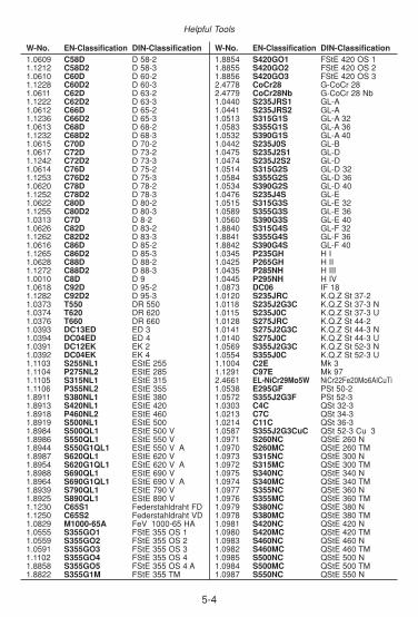
5-4
Helpful Tools
W-No. EN-Classification DIN-Classification1.0609 C58D D 58-21.1212 C58D2 D 58-31.0610 C60D D 60-21.1228 C60D2 D 60-31.0611 C62D D 63-21.1222 C62D2 D 63-31.0612 C66D D 65-21.1236 C66D2 D 65-31.0613 C68D D 68-21.1232 C68D2 D 68-31.0615 C70D D 70-21.0617 C72D D 73-21.1242 C72D2 D 73-31.0614 C76D D 75-21.1253 C76D2 D 75-31.0620 C78D D 78-21.1252 C78D2 D 78-31.0622 C80D D 80-21.1255 C80D2 D 80-31.0313 C7D D 8-21.0626 C82D D 83-21.1262 C82D2 D 83-31.0616 C86D D 85-21.1265 C86D2 D 85-31.0628 C88D D 88-21.1272 C88D2 D 88-31.0010 C8D D 91.0618 C92D D 95-21.1282 C92D2 D 95-31.0373 T550 DR 5501.0374 T620 DR 6201.0376 T660 DR 6601.0393 DC13ED ED 31.0394 DC04ED ED 41.0391 DC12EK EK 21.0392 DC04EK EK 41.1103 S255NL1 EStE 2551.1104 P275NL2 EStE 2851.1105 S315NL1 EStE 3151.1106 P355NL2 EStE 3551.8911 S380NL1 EStE 3801.8913 S420NL1 EStE 4201.8918 P460NL2 EStE 4601.8919 S500NL1 EStE 5001.8984 S500QL1 EStE 500 V1.8986 S550QL1 EStE 550 V1.8944 S550G1QL1 EStE 550 V A1.8987 S620QL1 EStE 620 V1.8954 S620G1QL1 EStE 620 V A1.8988 S690QL1 EStE 690 V1.8964 S690G1QL1 EStE 690 V A1.8939 S790QL1 EStE 790 V1.8925 S890QL1 EStE 890 V1.1230 C65S1 Federstahldraht FD1.1250 C65S2 Federstahldraht VD1.0829 M1000-65A FeV 1000-65 HA1.0555 S355GO1 FStE 355 OS 11.0559 S355GO2 FStE 355 OS 21.0591 S355GO3 FStE 355 OS 31.1102 S355GO4 FStE 355 OS 41.8858 S355GO5 FStE 355 OS 4 A1.8822 S355G1M FStE 355 TM
W-No. EN-Classification DIN-Classification1.8854 S420GO1 FStE 420 OS 11.8855 S420GO2 FStE 420 OS 21.8856 S420GO3 FStE 420 OS 32.4778 CoCr28 G-CoCr 282.4779 CoCr28Nb G-CoCr 28 Nb1.0440 S235JRS1 GL-A1.0441 S235JRS2 GL-A1.0513 S315G1S GL-A 321.0583 S355G1S GL-A 361.0532 S390G1S GL-A 401.0442 S235J0S GL-B1.0475 S235J2S1 GL-D1.0474 S235J2S2 GL-D1.0514 S315G2S GL-D 321.0584 S355G2S GL-D 361.0534 S390G2S GL-D 401.0476 S235J4S GL-E1.0515 S315G3S GL-E 321.0589 S355G3S GL-E 361.0560 S390G3S GL-E 401.8840 S315G4S GL-F 321.8841 S355G4S GL-F 361.8842 S390G4S GL-F 401.0345 P235GH H I1.0425 P265GH H II1.0435 P285NH H III1.0445 P295NH H IV1.0873 DC06 IF 181.0120 S235JRC K.Q.Z St 37-21.0118 S235J2G3C K.Q.Z St 37-3 N1.0115 S235J0C K.Q.Z St 37-3 U1.0128 S275JRC K.Q.Z St 44-21.0141 S275J2G3C K.Q.Z St 44-3 N1.0140 S275J0C K.Q.Z St 44-3 U1.0569 S355J2G3C K.Q.Z St 52-3 N1.0554 S355J0C K.Q.Z St 52-3 U1.1004 C2E Mk 31.1291 C97E Mk 972.4661 EL-NiCr29Mo5W NiCr22Fe20Mo6AlCuTi1.0538 E295GF PSt 50-21.0572 S355J2G3F PSt 52-31.0303 C4C QSt 32-31.0213 C7C QSt 34-31.0214 C11C QSt 36-31.0587 S355J2G3CuC QSt 52-3 Cu 31.0971 S260NC QStE 260 N1.0970 S260MC QStE 260 TM1.0973 S315NC QStE 300 N1.0972 S315MC QStE 300 TM1.0975 S340NC QStE 340 N1.0974 S340MC QStE 340 TM1.0977 S355NC QStE 360 N1.0976 S355MC QStE 360 TM1.0979 S380NC QStE 380 N1.0978 S380MC QStE 380 TM1.0981 S420NC QStE 420 N1.0980 S420MC QStE 420 TM1.0983 S460NC QStE 460 N1.0982 S460MC QStE 460 TM1.0985 S500NC QStE 500 N1.0984 S500MC QStE 500 TM1.0987 S550NC QStE 550 N

5-5
Conversion of Basic Units
W-No. EN-Classification DIN-Classification1.0986 S550MC QStE 550 TM1.8976 S650MC QStE 650 TM1.0703 C10RG2 R 10 S 101.0709 C7RG2 R 7 S 61.0337 DC04GT RoSt 41.0149 S275J0H RoSt 44-21.0138 S275J2H RoSt 44-31.0576 S355J2H RoSt 52-31.0122 S235JRG2C RQSt 37-21.0170 S235JRG2CuC RQSt 37-2 Cu 31.0351 C10W RRSD 101.0347 DC03 RRSt 3, RRSt 131.0319 L210GA RRStE 210.71.0459 L240GA RRStE 240.71.0398 DD12 RRStW 231.0339 C10WSi RSD 10 Si1.1115 C10EW RSD 111.0324 C8G2W RSD 71.0326 S180G2T RSt 281.0034 S205G2T RSt 34-21.0208 C10G2 RSt 35-21.0205 C11G2 RSt 361.0038 S235JRG2 RSt 37-21.0167 S235JRG2Cu RSt 37-2 Cu 31.0223 C14G2 RSt 381.3207 HS10-4-3-10 S 10-4-3-101.3318 HS12-1-2 S 12-1-21.3302 HS12-1-4 S 12-1-41.3202 HS12-1-4-5 S 12-1-4-51.3355 HS18-0-1 S 18-0-11.3265 HS18-1-2-10 S 18-1-2-101.3257 HS18-1-2-15 S 18-1-2-151.3255 HS18-1-2-5 S 18-1-2-51.3247 HS2-10-1-8 S 2-10-1-81.3346 HS2-9-1 S 2-9-11.3348 HS2-9-2 S 2-9-21.3249 HS2-9-2-8 S 2-9-2-81.3333 HS3-3-2 S 3-3-21.3343 HS6-5-2 S 6-5-21.3341 HS6-5-2S S 6-5-2 S1.3243 HS6-5-2-5 S 6-5-2-51.3245 HS6-5-2-5S S 6-5-2-5 S1.3344 HS6-5-3 S 6-5-31.3246 HS7-4-2-5 S 7-4-2-51.3342 HS6-5-2C SC 6-5-21.3340 HS6-5-2CS SC 6-5-2 S2.4623 EL-NiCr23Mo7Cu SG-NiCr23Mo7Cu1.1237 C70D3 SKD 701.1238 C80D3 SKD 801.0226 DX51D St 02 Z1.0350 DX52D St 03 Z1.0355 DX53D St 05 Z1.0306 DX54D St 06 Z1.0344 DC01Cu St 12 Cu 31.0354 DC04Cu St 14 Cu 31.0312 DC05 St 151.0318 S180GT St 281.0212 S215GAlT St 30 Al1.0211 S215GSiT St 30 Si1.0035 S185 St 331.0032 S205GT St 34-21.0308 S235G2T St 35
W-No. EN-Classification DIN-Classification1.0305 P235G1TH St 35.81.0254 P235T1 St 37.01.0255 P235T2 St 37.41.0315 P235G2TH St 37.81.0037 S235JR St 37-21.0169 S235JRCu+CR St 37-2 Cu 3 G1.0037 S235JR+CR St 37-2 G1.0116 S235J2G3 St 37-31.0166 S235J2G3Cu St 37-3 Cu 31.0116 S235J2G3+CR St 37-3 G1.0114 S235J0 St 37-3 U1.0338 DC04 St 4, St 141.0498 P255G2TH St 42.81.0256 P275T1 St 44.01.0257 P275T2 St 44.41.0044 S275JR St 44-21.0179 S275JRCu St 44-2 Cu 31.0144 S275J2G3 St 44-31.0144 S275J2G3+CR St 44-3 G1.0143 S275J0 St 44-3 U1.0408 S255GT St 451.0405 P255G1TH St 45.81.0050 E295 St 50-21.0050 E295+CR St 50-2 G1.0580 S355GT St 521.0421 P355T1 St 52.01.0581 P355T2 St 52.41.0570 S355J2G3 St 52-31.0585 S355J2G3Cu St 52-3 Cu 31.0585 S355J2G3Cu+CR St 52-3 Cu 3 G1.0570 S355J2G3+CR St 52-3 G1.0553 S355J0 St 52-3 U1.0060 E335 St 60-21.0060 E335+CR St 60-2 G1.0070 E360 St 70-21.0070 E360+CR St 70-2 G1.0307 L210 StE 210.71.0457 L245NB StE 240.71.0242 S250GD StE 250 Z1.0461 S255N StE 2551.0244 S280GD StE 280 Z1.0486 P275N StE 2851.0490 S275N StE 2851.0493 S275NH StE 2851.0484 L290NB StE 290.71.0429 L290MB StE 290.7 TM1.0505 P315N StE 3151.0250 S320GD StE 320 Z1.0409 L320 StE 320.71.0430 L320M StE 320.7 TM1.0529 S350GD StE 350 Z1.0562 P355N StE 3551.0545 S355N StE 3551.0539 S355NH StE 3551.8823 S355M StE 355 TM1.0582 L360NB StE 360.71.0578 L360MB StE 360.7 TM1.8900 S380N StE 3801.8970 L385N StE 385.71.8971 L385M StE 385.7 TM1.8972 L415NB StE 415.71.8973 L415MB StE 415.7 TM

5-6
Helpful Tools
W-No. EN-Classification DIN-Classification1.8902 S420N StE 4201.8825 S420M StE 420 TM1.8975 L450MB StE 445.7 TM1.8905 P460N StE 4601.8901 S460N StE 4601.8953 S460NH StE 4601.8827 S460M StE 460 TM1.8977 L485MB StE 480.7 TM1.8907 S500N StE 5001.8924 S500Q StE 500 V1.8904 S550Q StE 550 V1.8978 L555MB StE 550.7 TM1.8914 S620Q StE 620 V1.8931 S690Q StE 690 V1.8979 L690M StE 690.7 TM1.0915 R1100Cr StSch 11001.0631 R1200 StSch 12001.0422 R0550 StSch 5501.0544 R0600 StSch 6001.0521 R0700 StSch 7001.0524 R0800 StSch 8001.0623 R0900 StSch 900 A1.0624 R0900Mn StSch 900 B1.0341 R0290 StSchStr1.0021 S240GP StSp 371.0023 S270GP StSp 451.0083 S355GP StSp S1.0332 DD11 StW 221.0335 DD13 StW 241.0371 TH50 T 501.0372 TH52 T 521.0375 TH57 T 571.0377 TH61 T 611.0378 TH65 T 651.0463 S255NL TStE 2551.0488 P275NL1 TStE 2851.0491 S275NL TStE 2851.0497 S275NLH TStE 2851.0508 P315NL TStE 3151.0566 P355NL1 TStE 3551.0546 S355NL TStE 3551.0549 S355NLH TStE 3551.8834 S355ML TStE 355 TM1.8910 S380NL TStE 3801.8912 S420NL TStE 4201.8836 S420ML TStE 420 TM1.8915 P460NL1 TStE 4601.8903 S460NL TStE 4601.8956 S460NLH TStE 4601.8838 S460ML TStE 460 TM1.8906 S460QL TStE 460 V1.8917 S500NL TStE 5001.8909 S500QL TStE 500 V1.8926 S550QL TStE 550 V1.8923 S590QL TStE 590 V1.8927 S620QL TStE 620 V1.8928 S690QL TStE 690 V1.8920 S690G1QL TStE 690 V A1.8921 S690G2QL TStE 690 V B1.8922 S690G4QL TStE 690 V C1.8929 S690G3QL TStE 690 V D1.8938 S770QL TStE 770 V
W-No. EN-Classification DIN-Classification1.8983 S890QL TStE 890 V1.8933 S960QL TStE 960 V1.1101 S225NL TTSt 351.0702 C10RG1 U 10 S 101.0708 C7RG1 U 7 S 61.0348 P195GH UH I1.0160 S235JRG1F UPSt 37-21.0204 C11G1C UQSt 361.0121 S235JRG1C UQSt 37-21.0164 S235JRG1CuC UQSt 37-2 Cu 31.0224 C14G1C UQSt 381.1112 C8E1W USD 51.1116 C8E2W USD 61.0323 C8G1W USD 71.0357 S180G1T USt 281.0333 DC03G1 USt 3, USt 131.0028 S205G1T USt 34-21.0207 C10G1 USt 35-21.0203 C11G1 USt 361.0253 P235G1T1 USt 37.01.0036 S235JRG1 USt 37-21.0036 S235JRG1+CR USt 37-2 G1.0217 C14G1 USt 381.0336 DC04G1 USt 4, USt 141.0334 DD12G1 UStW 231.0834 M<35A V < 35 A1.0833 M>65A V > 65 A1.0832 M>65ASi V > 65 A Si1.0805 M>350-35A V >350-35 A1.0830 M1070-65A V 1070-65 A1.0818 M1450-50A V 1450-50 A1.0831 M1590-65A V 1590-65 A1.0800 M250-35A V 250-35 A1.0801 M270-35A V 270-35 A1.0806 M270-50A V 270-50 A1.0807 M290-50A V 290-50 A1.0803 M300-35A V 300-35 A1.0808 M310-50A V 310-50 A1.0804 M330-35A V 330-35 A1.0809 M330-50A V 330-50 A1.0819 M330-65A V 330-65 A1.0810 M350-50A V 350-50 A1.0820 M350-65A V 350-65 A1.0811 M400-50A V 400-50 A1.0821 M400-65A V 400-65 A1.0812 M470-50A V 470-50 A1.0823 M470-65A V 470-65 A1.0813 M530-50A V 530-50 A1.0824 M530-65A V 530-65 A1.0814 M600-50A V 600-50 A1.0825 M600-65A V 600-65 A1.0815 M700-50A V 700-50 A1.0826 M700-65A V 700-65 A1.0816 M800-50A V 800-50 A1.0827 M800-65A V 800-65 A1.0817 M940-50A V 940-50 A1.0828 M940-65A V 940-65 A1.0840 M<50E VE < 501.0850 M>65E VE > 651.0841 M340-50E VE 340-501.0842 M390-50E VE 390-501.0846 M390-65E VE 390-65
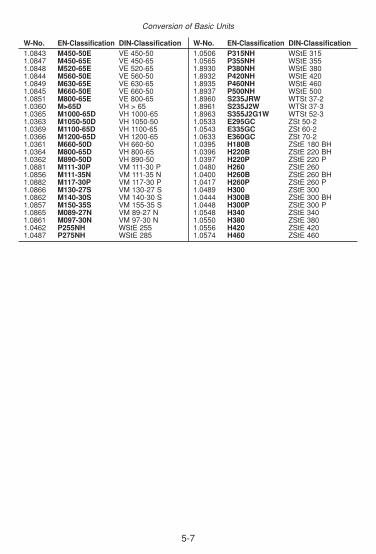
5-7
Conversion of Basic Units
W-No. EN-Classification DIN-Classification1.0843 M450-50E VE 450-501.0847 M450-65E VE 450-651.0848 M520-65E VE 520-651.0844 M560-50E VE 560-501.0849 M630-65E VE 630-651.0845 M660-50E VE 660-501.0851 M800-65E VE 800-651.0360 M>65D VH > 651.0365 M1000-65D VH 1000-651.0363 M1050-50D VH 1050-501.0369 M1100-65D VH 1100-651.0366 M1200-65D VH 1200-651.0361 M660-50D VH 660-501.0364 M800-65D VH 800-651.0362 M890-50D VH 890-501.0881 M111-30P VM 111-30 P1.0856 M111-35N VM 111-35 N1.0882 M117-30P VM 117-30 P1.0866 M130-27S VM 130-27 S1.0862 M140-30S VM 140-30 S1.0857 M150-35S VM 155-35 S1.0865 M089-27N VM 89-27 N1.0861 M097-30N VM 97-30 N1.0462 P255NH WStE 2551.0487 P275NH WStE 285
W-No. EN-Classification DIN-Classification1.0506 P315NH WStE 3151.0565 P355NH WStE 3551.8930 P380NH WStE 3801.8932 P420NH WStE 4201.8935 P460NH WStE 4601.8937 P500NH WStE 5001.8960 S235JRW WTSt 37-21.8961 S235J2W WTSt 37-31.8963 S355J2G1W WTSt 52-31.0533 E295GC ZSt 50-21.0543 E335GC ZSt 60-21.0633 E360GC ZSt 70-21.0395 H180B ZStE 180 BH1.0396 H220B ZStE 220 BH1.0397 H220P ZStE 220 P1.0480 H260 ZStE 2601.0400 H260B ZStE 260 BH1.0417 H260P ZStE 260 P1.0489 H300 ZStE 3001.0444 H300B ZStE 300 BH1.0448 H300P ZStE 300 P1.0548 H340 ZStE 3401.0550 H380 ZStE 3801.0556 H420 ZStE 4201.0574 H460 ZStE 460

Böhler Schweißtechnik Austria GmbHBöhler-Welding-St. 1, 8605 Kapfenberg / AUSTRIAPhone: +43 (0) 3862-301-0Fax: +43 (0) 3862-301-95193E-Mail: [email protected]://www.boehler-welding.com
Böhler Schweißtechnik Austria GmbHBöhler-Welding-St. 18605 Kapfenberg / AUSTRIA
+43 (0) 3862-301-0+43 (0) [email protected]
www.boehler-welding.comMember of the BÖHLER-UDDEHOLM Group
Published by BÖHLER WELDING
BSG
A 0
9/20
06
EN
G60
00


