Wet etching technique for fabrication of GaSb based mid
infrared single lateral mode lasers
Seungyong Jung, Sergey Suchalkin, Leon Shterengas, Gela Kipshidze,
and Gregory Belenky
06.24.2011
Outline
• Motivation
• Technology description
• Device fabrication
• Result and discussion
• Summary

Applications of Mid IR Lasers
<Applications>- Gas detection- Free space communication- Medical diagnostics
<Schematic of the narrow ridge laser>
Absorption spectra of various gaseswithin Mid IR (2 ~ 5 µm) range
A. Krier et al, phys. stat. sol. (a) 205, No. 1, 129–143 (2008)
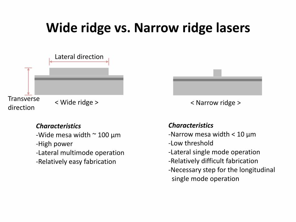
Wide ridge vs. Narrow ridge lasers
Characteristics-Wide mesa width ~ 100 µm-High power -Lateral multimode operation-Relatively easy fabrication
Characteristics-Narrow mesa width < 10 µm-Low threshold-Lateral single mode operation-Relatively difficult fabrication-Necessary step for the longitudinal
single mode operation
Lateral direction
Transverse direction
< Wide ridge > < Narrow ridge >

Crucial points to fabricate the narrow ridge
2. Etching depth control
1. WG width control
GaSb Substrate
Waveguide Cladding (p)AlGaAsSb
GradingCap: GaSb
Waveguide CoreInGaSb/AlGaAsSb
Waveguide Cladding (n)AlGaAsSb
< Typical GaSb based mid IR laser QW laser structure>
Lateral single mode requires the precise refractive index step (n1-n2) controltogether with the mesa width.0
n1n2 n2

Fabrication of narrow ridge
<Dry etching>
Advantages Precise control of etching depth High degree of Directivity High degree of non-selective etching
Disadvantages High cost Low throughput
<Wet etching>
Advantages Cost effective High throughput Relatively easy implementationHigh degree of material selectivity
Disadvantages Low degree of directivity High degree of material selectivity
Could be preferred to industrial process.

Implementation challenges using wet etching
Material selectivity Isotropic etching profile
< Etching test with Tartrate based solution>< Etching test with HCl based solution>
Fast etching rate for Al-rich material Fast etching rate for non Al-rich material
Al0.85GaAsSb
Al0.85GaAsSb

Two major points of this technique
Etch Stopper
- Role:To control precise etching depth
- Requirement:1. Slow etching rate with HCl2. Need to minimize carrier
transport problem
Proper material selection
AlInGaAsSb
Complementary Etching
- Role:To compensate etching selectivitybetween the GaSb and AlGaAsSb layer.
- Procedure:1. Etching GaSb with Tartrate solution2. Etching AlGaAsSb with HCl solution

Preliminary wet etching result
GaSb
AlGaAsSb
AlInGaAsSb(Stopper)
AlGaAsSb
<Etching test with the etch stopper>

Processing detail: Etchant preparation
<Tartrate based solution>
Tartrate : DI Water : H2O2 : H3PO4
=5 g : 90 ml : 30 ml : 30 ml
Under stirring for 2 days
<HCl based solution>
HCl : DI Water : H2O2
= 50 ml : 50 ml : 1 ml
H2O2 was added just before used.
Material GaSb AlGaAsSb AlInGaAsSb
Role Cap Cladding Etch stopper
Etching rate of Tartrate (nm/sec)
16.6 5 -
Etching rate of HCl(nm/sec)
3.2 30 1.1
<Etching rate of etch etchant>
Highly selective!

Processing detail: Etching Procedure
Etching cap+grading
Etchingthe p-clad
Metal layerGrading
GaSb
Cladding
Etch stop layer
<1. Metal deposition> <2. Etching with the Tartrate solution>
<3. Etching with the HCl solution><4. Photo-resist removal>
PR
PR
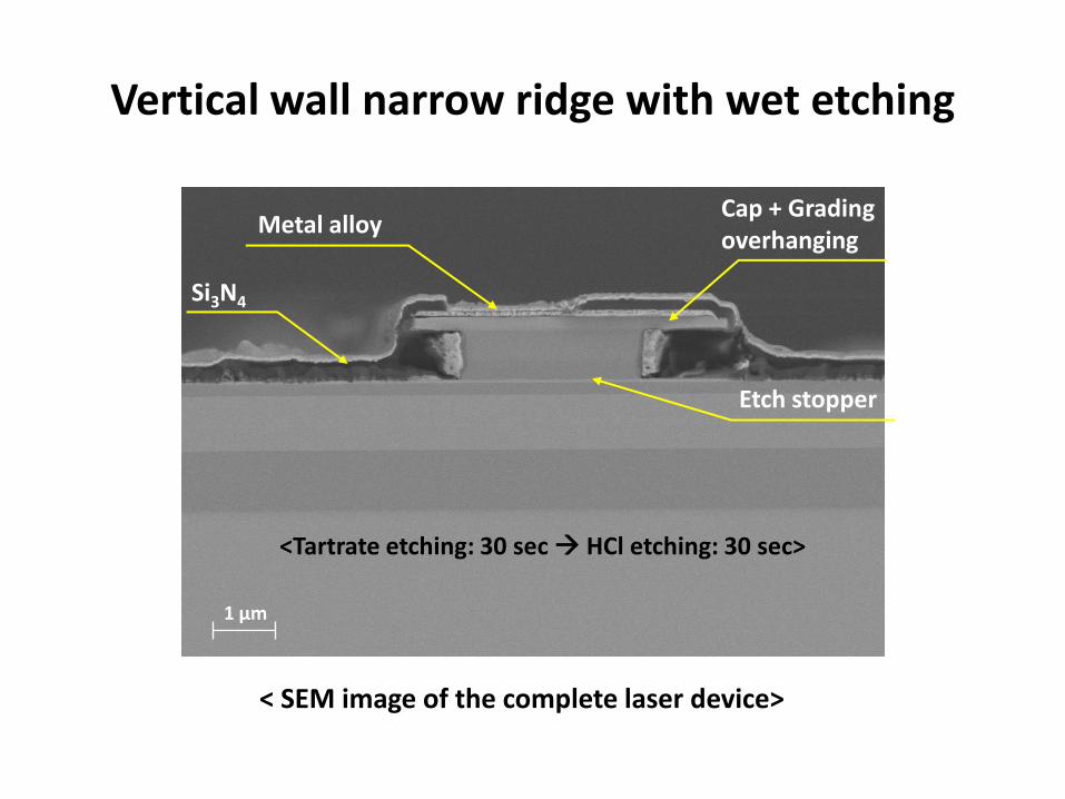
Vertical wall narrow ridge with wet etching
Etch stopper
Si3N4
Metal alloyCap + Grading overhanging
1 µm
<Tartrate etching: 30 sec HCl etching: 30 sec>
< SEM image of the complete laser device>

<4.2 um (12 μm) >
<2.4 μm (10 μm) > <0.5 μm (8 μm) >
Mesa width control
Various PR widthsPR

Laser performance
RT cw power: ~70mW Far field at slow axis: ~8˚ (FWHM)
0.00 0.05 0.10 0.15 0.20 0.25 0.30 0.35 0.400
10
20
30
40
50
60
70
0.0
0.5
1.0
1.5
2.0
2.5
3.0
1.95 2.00 2.05 2.10
T=20oC, CW
730_S#1
coated(HR95%, AR5%)
L=2mm
Po
we
r (m
W)
Current (A)
Vo
lta
ge
(V
) Wavelength (m)
-20 -15 -10 -5 0 5 10 15 200.0
0.5
1.0
1.5
2.0
2.5
FWHM~9o
400mA
FWHM~8o
300mA
FWHM~7o
200mA
FWHM~7o
100mA
No
rma
lize
d I
nte
ns
ity
(a
. u
.)Angle(degree)
C730S#1, np5, AR/HR
6 m wide, 2mm long
7s, 10kHz, 20oC
Far field, slow axis

Summary and Future work
<Summary>
• The lateral single mode laser has been fabricated by cost effective wet etching technique.
• Complementary etching with the etch stopper demonstrated effective mesa width and etching depth control.
• This technique can be used for sidewall smoothing, standing free 2D wire, etc. consisting of Al-rich and InGaAsSb sequential layers.
< Future work>
• Optimization of the etching process for precise etching control.
Sponsored by


