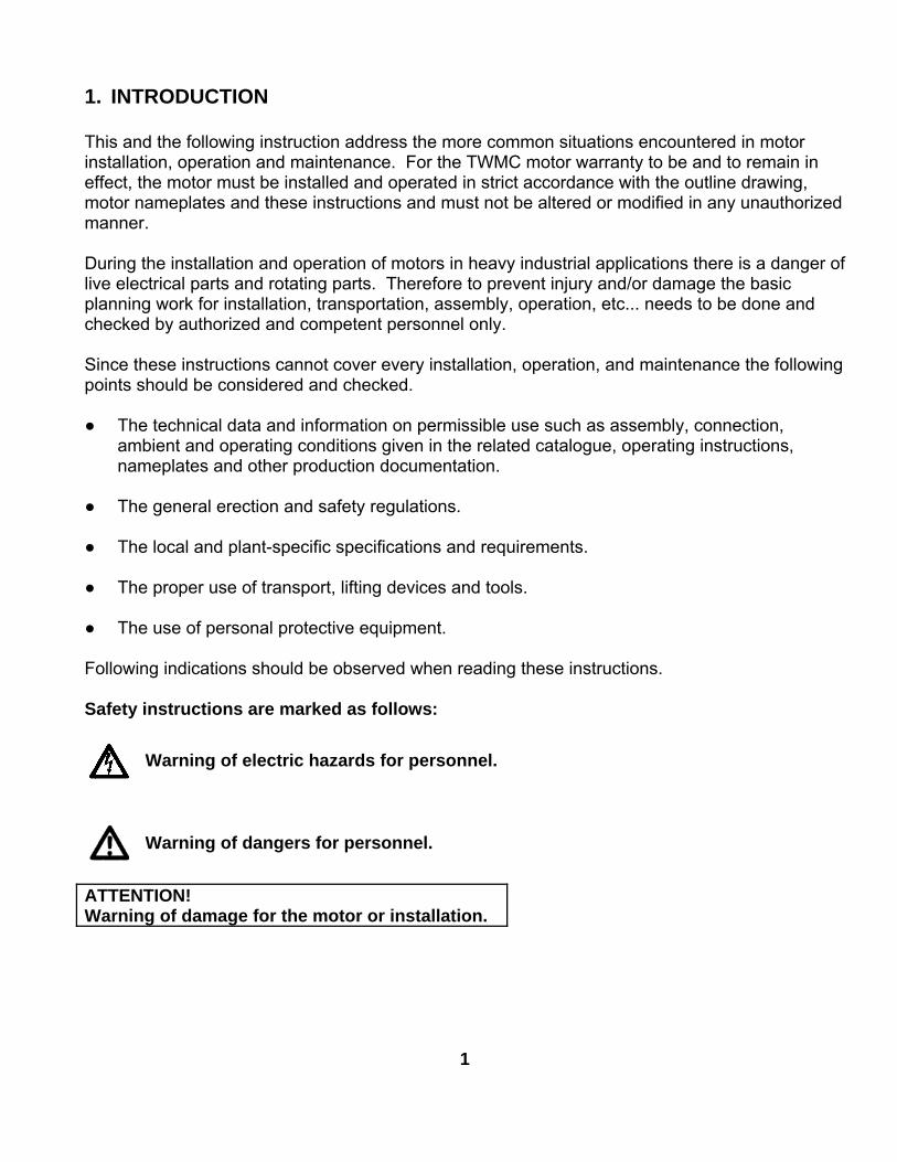
NAMEPLATE INFORMATION
HP KW
400 298 60
TYPICAL PERFORMANCE
0
OUTPUTPOLE
2
FRAMESIZE
5009A
ISSUED
12/27/13
TYPE
AEHH8N
ENCLOSURE
TEFC
CATALOG#
EP4002
PERFORMANCE DATA3-PHASE INDUCTION MOTOR
INS.CLASS
F
NEMADESIGN
B
VOLTAGE
460
HZRATED
AMBIENT
40oC
TIMERATING
CONT.
SERVICEFACTOR
1.15
EFFICIENCY
630
INERTIA
90.5 87
1/2 LOAD%
95 95.8 95.4 94
FULL LOADMIN. % NOM. %
3/4 LOAD%
MAXIMUMPOWER FACTOR
CORRECTION
KVAR583575
FULLLOADRPM
POWER FACTOR3/4 LOAD
%1/2 LOAD
%F. L.%
91.6
ACCEL TIME
4.70230 8.60
NEMALOAD
WK2
Sec
MAXALLOWABLE
WK2
Sec
NEMALOAD
WK2
lb-ft2
G
65.7
ROTOR
WR2
lb-ft2
TORQUE
FULL LOADlb-ft
LOCKEDROTOR%FLT
PULLUP
%FLT
BREAKDOWN%FLT
315
MAXALLOWABLE
WK2
lb-ft2
587 85 85
SOUNDPRESSURE
LEVEL @ 3 FTdB(A)HOT
ALLOWABLESTARTS
PER HOUR
SAFE STALLTIME IN
SECONDS
851 2
COLD
NEMA KVACODE LETTER
APPROVED: REVISION
COLD HOT
28 20
M. PRATER DRAWING NO. 3A057EP4002
LOCKED ROTOR
2900
CURRENTS
NO LOAD FULL LOAD
72.6 427
DATE: CATALOG NO.:
March 30, 2006 EP4002
DWG NO.
DAC-1545-3
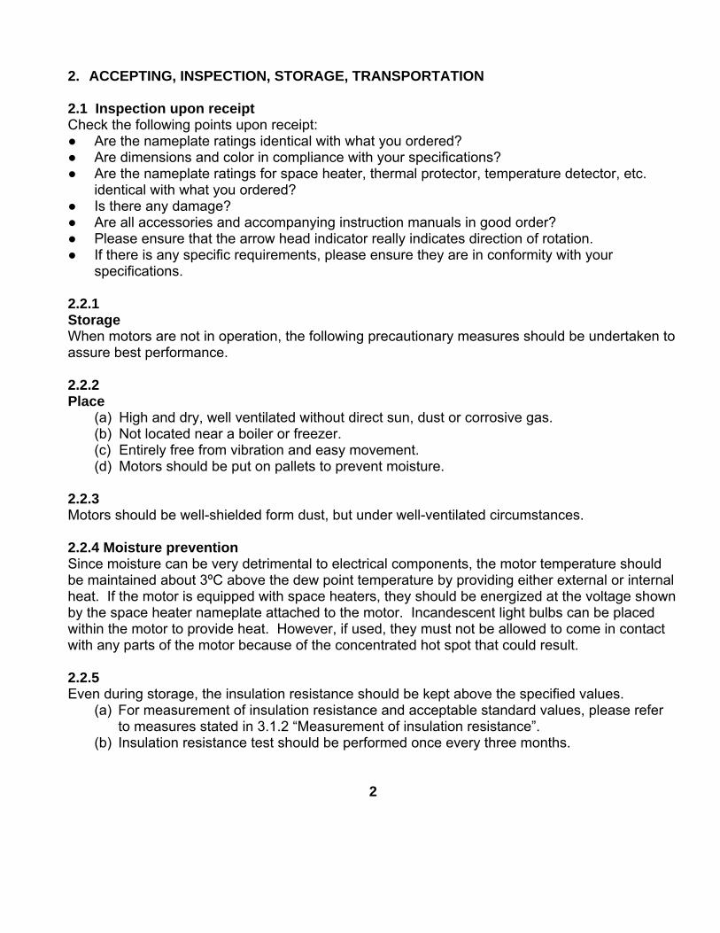
WYE START-DELTA RUN CONNECTION
460 VOLT CONNECTION
LINE LINE460 VOLT START 460 VOLT RUN
CONNECTION DIAGRAM
SCHEMATIC - Δ / Y CONNECTION
ACROSS THE LINE CONNECTION

OPERATION&
MAINTENANCEMANUAL
FORTHREE PHASE
INDUCTIONMOTORS
TECO-Westinghouse Motor Company5100 North IH-35
Round Rock, Tx. 78681
Frame Size 5000 and Larger
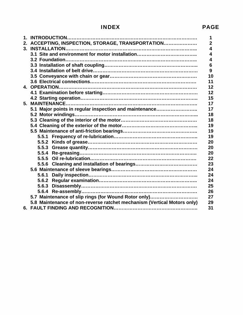
INDEX PAGE
1. INTRODUCTION……………………………………………………………………….2. ACCEPTING, INSPECTION, STORAGE, TRANSPORTATION…………………3. INSTALLATION………………………………………………………………………..
3.1 Site and environment for motor installation………………………………..3.2 Foundation………………………………………………………………………..3.3 Installation of shaft coupling…………………………………………………..3.4 Installation of belt drive…………………………………………………………3.5 Conveyance with chain or gear……………………………………………….3.6 Electrical connections………………………………………………………….
4. OPERATION……………………………………………………………………………4.1 Examination before starting……………………………………………………4.2 Starting operation………………………………………………………………..
5. MAINTENANCE………………………………………………………………………..5.1 Major points in regular inspection and maintenance……………………..5.2 Motor windings…………………………………………………………………...5.3 Cleaning of the interior of the motor…………………………………………5.4 Cleaning of the exterior of the motor………………………………………...5.5 Maintenance of anti-friction bearings………………………………………..
5.5.1 Frequency of re-lubrication……………………………………………..5.5.2 Kinds of grease……………………………………………………………5.5.3 Grease quantity……………………………………………………………5.5.4 Re-greasing………………………………………………………………..5.5.5 Oil re-lubrication………………………………………………………….5.5.6 Cleaning and installation of bearings…………………………………
5.6 Maintenance of sleeve bearings………………………………………………5.6.1 Daily inspection…………………………………………………………...5.6.2 Regular examination……………………………………………………..5.6.3 Disassembly……………………………………………………………….5.6.4 Re-assembly……………………………………………………………….
5.7 Maintenance of slip rings (for Wound Rotor only)…………………………5.8 Maintenance of non-reverse ratchet mechanism (Vertical Motors only)
6. FAULT FINDING AND RECOGNITION……………………………………………..
124446910111212151717181819191920202022232424242526272931
1. INTRODUCTION
This and the following instruction address the more common situations encountered in motorinstallation, operation and maintenance. For the TWMC motor warranty to be and to remain ineffect, the motor must be installed and operated in strict accordance with the outline drawing,motor nameplates and these instructions and must not be altered or modified in any unauthorizedmanner.
During the installation and operation of motors in heavy industrial applications there is a danger oflive electrical parts and rotating parts. Therefore to prevent injury and/or damage the basicplanning work for installation, transportation, assembly, operation, etc... needs to be done andchecked by authorized and competent personnel only.
Since these instructions cannot cover every installation, operation, and maintenance the followingpoints should be considered and checked.
The technical data and information on permissible use such as assembly, connection,ambient and operating conditions given in the related catalogue, operating instructions,nameplates and other production documentation.
The general erection and safety regulations.
The local and plant-specific specifications and requirements.
The proper use of transport, lifting devices and tools.
The use of personal protective equipment.
Following indications should be observed when reading these instructions.
Safety instructions are marked as follows:
Warning of electric hazards for personnel.
Warning of dangers for personnel.
ATTENTION!Warning of damage for the motor or installation.
1
2. ACCEPTING, INSPECTION, STORAGE, TRANSPORTATION
2.1 Inspection upon receiptCheck the following points upon receipt: Are the nameplate ratings identical with what you ordered? Are dimensions and color in compliance with your specifications? Are the nameplate ratings for space heater, thermal protector, temperature detector, etc.
identical with what you ordered? Is there any damage? Are all accessories and accompanying instruction manuals in good order? Please ensure that the arrow head indicator really indicates direction of rotation. If there is any specific requirements, please ensure they are in conformity with your
specifications.
2.2.1StorageWhen motors are not in operation, the following precautionary measures should be undertaken toassure best performance.
2.2.2Place
(a) High and dry, well ventilated without direct sun, dust or corrosive gas.(b) Not located near a boiler or freezer.(c) Entirely free from vibration and easy movement.(d) Motors should be put on pallets to prevent moisture.
2.2.3Motors should be well-shielded form dust, but under well-ventilated circumstances.
2.2.4 Moisture preventionSince moisture can be very detrimental to electrical components, the motor temperature shouldbe maintained about 3ºC above the dew point temperature by providing either external or internalheat. If the motor is equipped with space heaters, they should be energized at the voltage shownby the space heater nameplate attached to the motor. Incandescent light bulbs can be placedwithin the motor to provide heat. However, if used, they must not be allowed to come in contactwith any parts of the motor because of the concentrated hot spot that could result.
2.2.5Even during storage, the insulation resistance should be kept above the specified values.
(a) For measurement of insulation resistance and acceptable standard values, please referto measures stated in 3.1.2 “Measurement of insulation resistance”.
(b) Insulation resistance test should be performed once every three months.
2
2.2.6If the motor is not in operation for a long period (one week and above) after installation or hasbeen in operation but stopped for a period of time, the following precautions must be taken.
(a) Protect the motor as measures stated in 2.2.5.(b) Insulation resistance test should be performed as stated in 2.3.6.
2.2.7 Bearing protection
(a) If the motor has been provided with a shaft shipping brace to prevent shaft movementduring transit, it must be removed before operating the motor. It is very important thatthis brace be re-installed exactly as it was originally, before the motor is moved fromstorage or any time when the motor is being transported. This prevents axial rotormovement that might damage the bearings.
(b) Motors equipped with sleeve bearings are shipped from the factory with the bearing oilreservoirs drained. In storage, the oil reservoirs should be properly filled to the center ofthe oil level gauge with a good grade of rust inhibiting oil. This will keep the bearingjournals well oiled to prevent rusting. The motor shaft should be rotated severalrevolutions every month ensuring the shaft does not come to rest in its original position.While the shaft is rotating, it should be pushed to both extremes of the endplay.
(c) Motors with anti-friction bearings are properly lubricated with the correct grade of greaseat the factory and no further greasing is required in storage. The shaft should be rotatedseveral revolutions every month to maintain proper distribution of the grease within thebearings.
(d) Tilt-pad bearings are a type of sleeve bearing used in special design applications. Due tothe nature of this bearing, a loose oil ring for delivering lubricant cannot be provided.Therefore, during the storage internal, oil must be periodically manually introduced intothe pads and housing to prevent the occurrence of oxidation of the precision machinedcomponents.(1) Remove the pipe plug from the bearing cap located above the tilt-bearing shell.(2) Pour in approximately one cup of oil every month and rotate the shaft a few
revolutions about every two (2) weeks.(3) For long periods of storage, the oil that accumulates in the housing should be
removed.2.2.8ATTENTION!Care should be taken to keep parts such as fitting surfaces, key, shaft extension and axialcentral hole from any collision with foreign matter. Grease should also be generouslyapplied to prevent rusting.
2.2.9 TransportationTo keep the rotating parts of motors from moving, thus preventing damage and scratching duringtransportation, they should be held securely with a locking device. Remove all transit clampsbefore operating the motor. It is very important that this device be reinstalled exactly as it wasoriginally, before the motor is moved from storage or any time when the motor is beingtransported. The vertical mounting type motors should be transported in the vertical position.
3
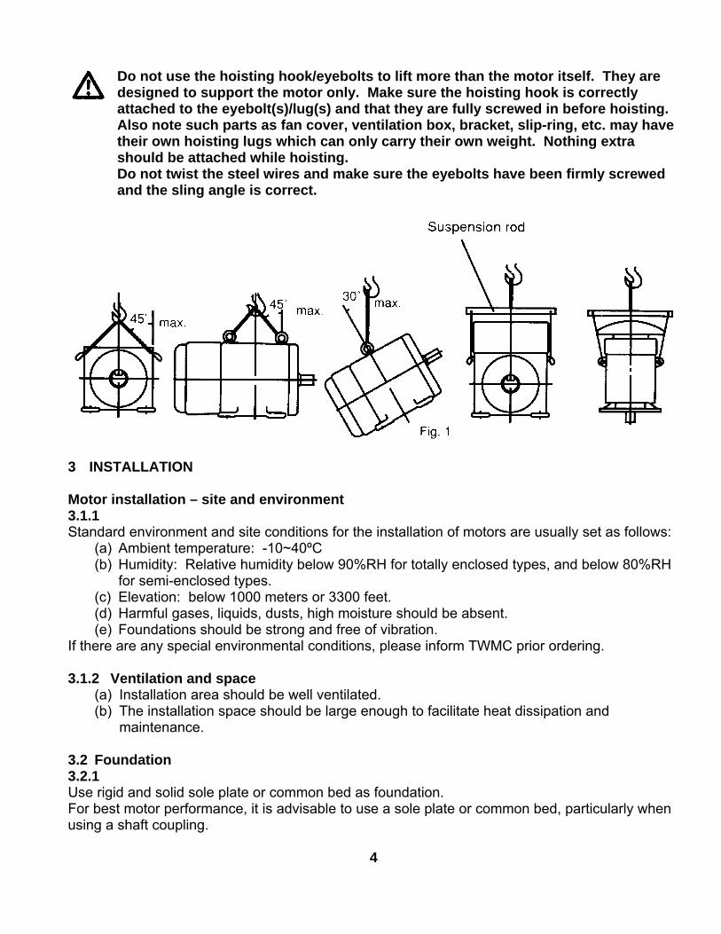
Do not use the hoisting hook/eyebolts to lift more than the motor itself. They aredesigned to support the motor only. Make sure the hoisting hook is correctlyattached to the eyebolt(s)/lug(s) and that they are fully screwed in before hoisting.Also note such parts as fan cover, ventilation box, bracket, slip-ring, etc. may havetheir own hoisting lugs which can only carry their own weight. Nothing extrashould be attached while hoisting.Do not twist the steel wires and make sure the eyebolts have been firmly screwedand the sling angle is correct.
3 INSTALLATION
Motor installation – site and environment3.1.1Standard environment and site conditions for the installation of motors are usually set as follows:
(a) Ambient temperature: -10~40ºC(b) Humidity: Relative humidity below 90%RH for totally enclosed types, and below 80%RH
for semi-enclosed types.(c) Elevation: below 1000 meters or 3300 feet.(d) Harmful gases, liquids, dusts, high moisture should be absent.(e) Foundations should be strong and free of vibration.
If there are any special environmental conditions, please inform TWMC prior ordering.
3.1.2 Ventilation and space(a) Installation area should be well ventilated.(b) The installation space should be large enough to facilitate heat dissipation and
maintenance.
3.2 Foundation3.2.1Use rigid and solid sole plate or common bed as foundation.For best motor performance, it is advisable to use a sole plate or common bed, particularly whenusing a shaft coupling.
4
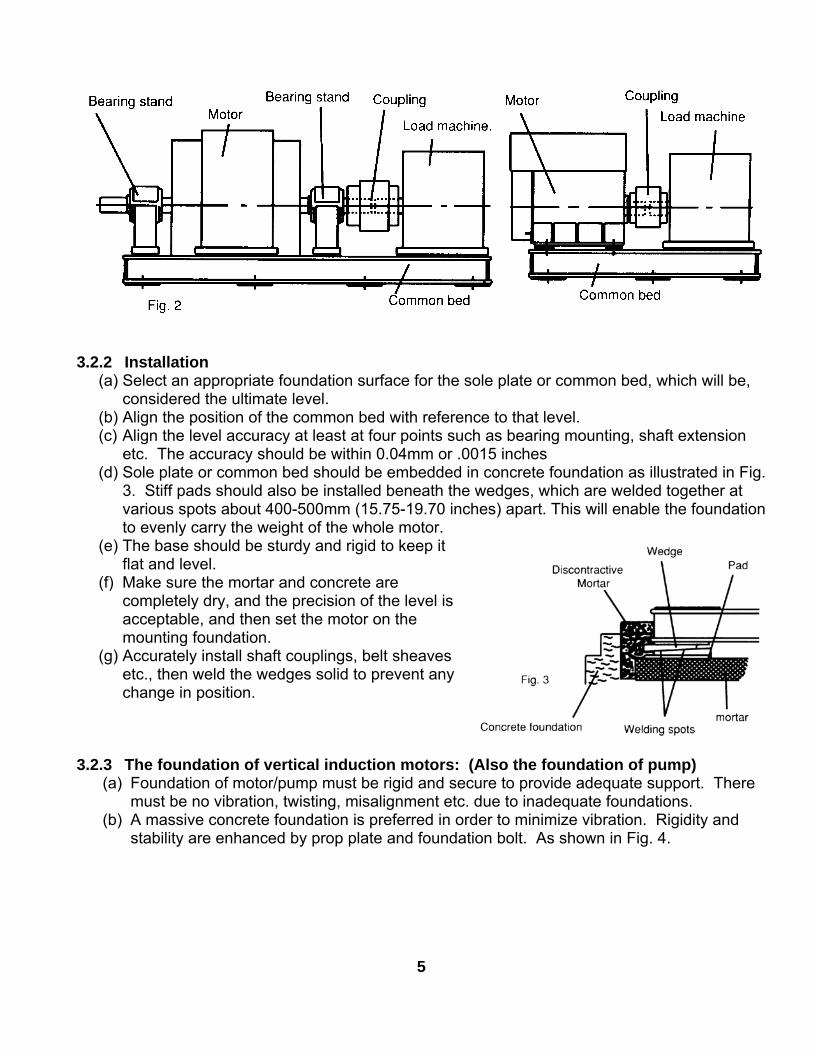
3.2.2 Installation(a) Select an appropriate foundation surface for the sole plate or common bed, which will be,
considered the ultimate level.(b) Align the position of the common bed with reference to that level.(c) Align the level accuracy at least at four points such as bearing mounting, shaft extension
etc. The accuracy should be within 0.04mm or .0015 inches(d) Sole plate or common bed should be embedded in concrete foundation as illustrated in Fig.
3. Stiff pads should also be installed beneath the wedges, which are welded together atvarious spots about 400-500mm (15.75-19.70 inches) apart. This will enable the foundationto evenly carry the weight of the whole motor.
(e) The base should be sturdy and rigid to keep itflat and level.
(f) Make sure the mortar and concrete arecompletely dry, and the precision of the level isacceptable, and then set the motor on themounting foundation.
(g) Accurately install shaft couplings, belt sheavesetc., then weld the wedges solid to prevent anychange in position.
3.2.3 The foundation of vertical induction motors: (Also the foundation of pump)(a) Foundation of motor/pump must be rigid and secure to provide adequate support. There
must be no vibration, twisting, misalignment etc. due to inadequate foundations.(b) A massive concrete foundation is preferred in order to minimize vibration. Rigidity and
stability are enhanced by prop plate and foundation bolt. As shown in Fig. 4.
5
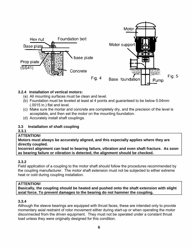
3.2.4 Installation of vertical motors:(a) All mounting surfaces must be clean and level.(b) Foundation must be leveled at least at 4 points and guaranteed to be below 0.04mm
(.0015 in.) flat and level.(c) Make sure the mortar and concrete are completely dry, and the precision of the level is
acceptable, and then set the motor on the mounting foundation.(d) Accurately install shaft couplings.
3.3 Installation of shaft coupling3.3.1ATTENTION!Motors must always be accurately aligned, and this especially applies where they aredirectly coupled.Incorrect alignment can lead to bearing failure, vibration and even shaft fracture. As soonas bearing failure or vibration is detected, the alignment should be checked.
3.3.2Field application of a coupling to the motor shaft should follow the procedures recommended bythe coupling manufacturer. The motor shaft extension must not be subjected to either extremeheat or cold during coupling installation.
ATTENTION!Basically, the coupling should be heated and pushed onto the shaft extension with slightaxial force. To prevent damages to the bearing do not hammer the coupling.
3.3.4Although the sleeve bearings are equipped with thrust faces, these are intended only to providemomentary axial restraint of rotor movement either during start-up or when operating the motordisconnected from the driven equipment. They must not be operated under a constant thrustload unless they were originally designed for this condition.
6
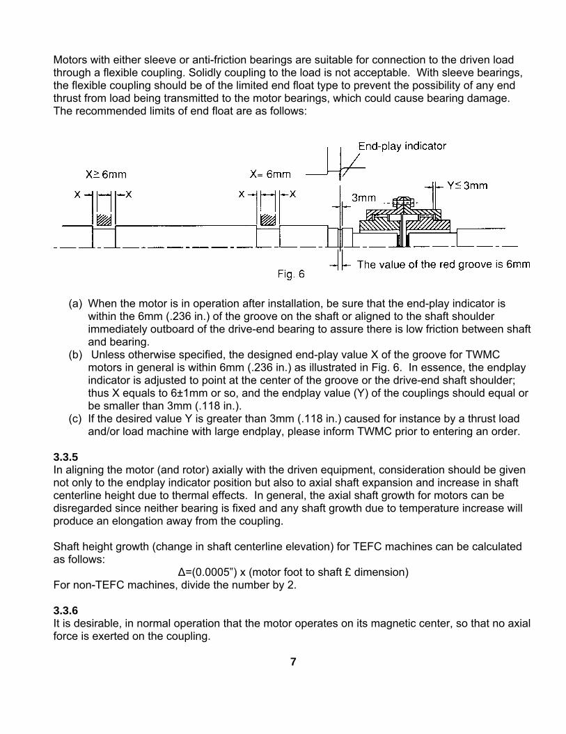
Motors with either sleeve or anti-friction bearings are suitable for connection to the driven loadthrough a flexible coupling. Solidly coupling to the load is not acceptable. With sleeve bearings,the flexible coupling should be of the limited end float type to prevent the possibility of any endthrust from load being transmitted to the motor bearings, which could cause bearing damage.The recommended limits of end float are as follows:
(a) When the motor is in operation after installation, be sure that the end-play indicator iswithin the 6mm (.236 in.) of the groove on the shaft or aligned to the shaft shoulderimmediately outboard of the drive-end bearing to assure there is low friction between shaftand bearing.
(b) Unless otherwise specified, the designed end-play value X of the groove for TWMCmotors in general is within 6mm (.236 in.) as illustrated in Fig. 6. In essence, the endplayindicator is adjusted to point at the center of the groove or the drive-end shaft shoulder;thus X equals to 6±1mm or so, and the endplay value (Y) of the couplings should equal orbe smaller than 3mm (.118 in.).
(c) If the desired value Y is greater than 3mm (.118 in.) caused for instance by a thrust loadand/or load machine with large endplay, please inform TWMC prior to entering an order.
3.3.5In aligning the motor (and rotor) axially with the driven equipment, consideration should be givennot only to the endplay indicator position but also to axial shaft expansion and increase in shaftcenterline height due to thermal effects. In general, the axial shaft growth for motors can bedisregarded since neither bearing is fixed and any shaft growth due to temperature increase willproduce an elongation away from the coupling.
Shaft height growth (change in shaft centerline elevation) for TEFC machines can be calculatedas follows:
∆=(0.0005”) x (motor foot to shaft £ dimension)For non-TEFC machines, divide the number by 2.
3.3.6It is desirable, in normal operation that the motor operates on its magnetic center, so that no axialforce is exerted on the coupling.
7
The motor shaft and the driven shaft should be aligned within the following tolerances in bothangular and parallel alignment:
Unit: mmTIR Range of rotating speed Solid coupling Flexible coupling
2500 rpm and above 0.03 0.03C Below 2500 rpm 0.04 0.052500 rpm and above 0.03 0.03A Below 2500 rpm 0.03 0.04
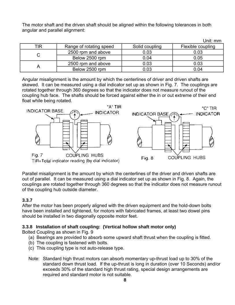
Angular misalignment is the amount by which the centerlines of driver and driven shafts areskewed. It can be measured using a dial indicator set up as shown in Fig. 7. The couplings arerotated together through 360 degrees so that the indicator does not measure runout of thecoupling hub face. The shafts should be forced against either the in or out extreme of their endfloat while being rotated.
Parallel misalignment is the amount by which the centerlines of the driver and driven shafts areout of parallel. It can be measured using a dial indicator set up as shown in Fig. 8. Again, thecouplings are rotated together through 360 degrees so that the indicator does not measure runoutof the coupling hub outside diameter.
3.3.7After the motor has been properly aligned with the driven equipment and the hold-down boltshave been installed and tightened, for motors with fabricated frames, at least two dowel pinsshould be installed in two diagonally opposite motor feet.
3.3.8 Installation of shaft coupling: (Vertical hollow shaft motor only)Bolted Coupling as shown in Fig. 9
(a) Bearings are provided to absorb some upward shaft thrust when the coupling is fitted.(b) The coupling is fastened with bolts.(c) This coupling type is not auto-release type.
Note: Standard high thrust motors can absorb momentary up-thrust load up to 30% of thestandard down thrust load. If the up-thrust is long in duration (over 10 Seconds) and/orexceeds 30% of the standard high thrust rating, special design arrangements arerequired and standard motor is not suitable.
8
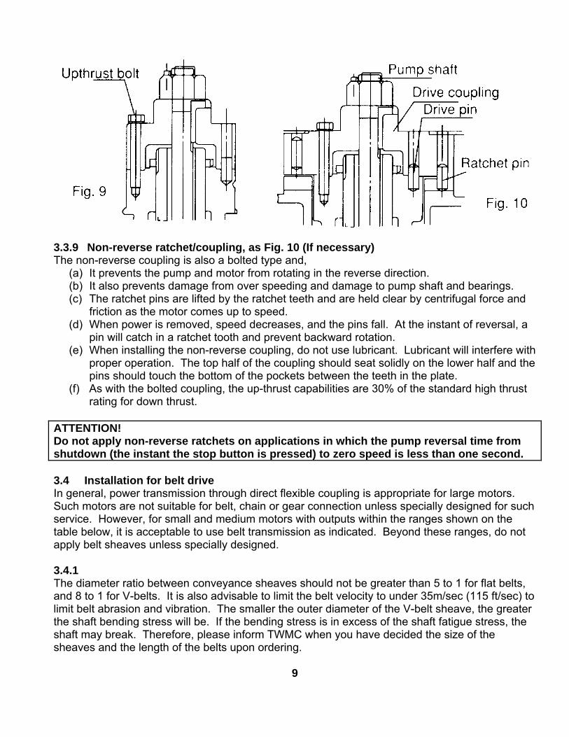
3.3.9 Non-reverse ratchet/coupling, as Fig. 10 (If necessary)The non-reverse coupling is also a bolted type and,
(a) It prevents the pump and motor from rotating in the reverse direction.(b) It also prevents damage from over speeding and damage to pump shaft and bearings.(c) The ratchet pins are lifted by the ratchet teeth and are held clear by centrifugal force and
friction as the motor comes up to speed.(d) When power is removed, speed decreases, and the pins fall. At the instant of reversal, a
pin will catch in a ratchet tooth and prevent backward rotation.(e) When installing the non-reverse coupling, do not use lubricant. Lubricant will interfere with
proper operation. The top half of the coupling should seat solidly on the lower half and thepins should touch the bottom of the pockets between the teeth in the plate.
(f) As with the bolted coupling, the up-thrust capabilities are 30% of the standard high thrustrating for down thrust.
ATTENTION!Do not apply non-reverse ratchets on applications in which the pump reversal time fromshutdown (the instant the stop button is pressed) to zero speed is less than one second.
3.4 Installation for belt driveIn general, power transmission through direct flexible coupling is appropriate for large motors.Such motors are not suitable for belt, chain or gear connection unless specially designed for suchservice. However, for small and medium motors with outputs within the ranges shown on thetable below, it is acceptable to use belt transmission as indicated. Beyond these ranges, do notapply belt sheaves unless specially designed.
3.4.1The diameter ratio between conveyance sheaves should not be greater than 5 to 1 for flat belts,and 8 to 1 for V-belts. It is also advisable to limit the belt velocity to under 35m/sec (115 ft/sec) tolimit belt abrasion and vibration. The smaller the outer diameter of the V-belt sheave, the greaterthe shaft bending stress will be. If the bending stress is in excess of the shaft fatigue stress, theshaft may break. Therefore, please inform TWMC when you have decided the size of thesheaves and the length of the belts upon ordering.
9
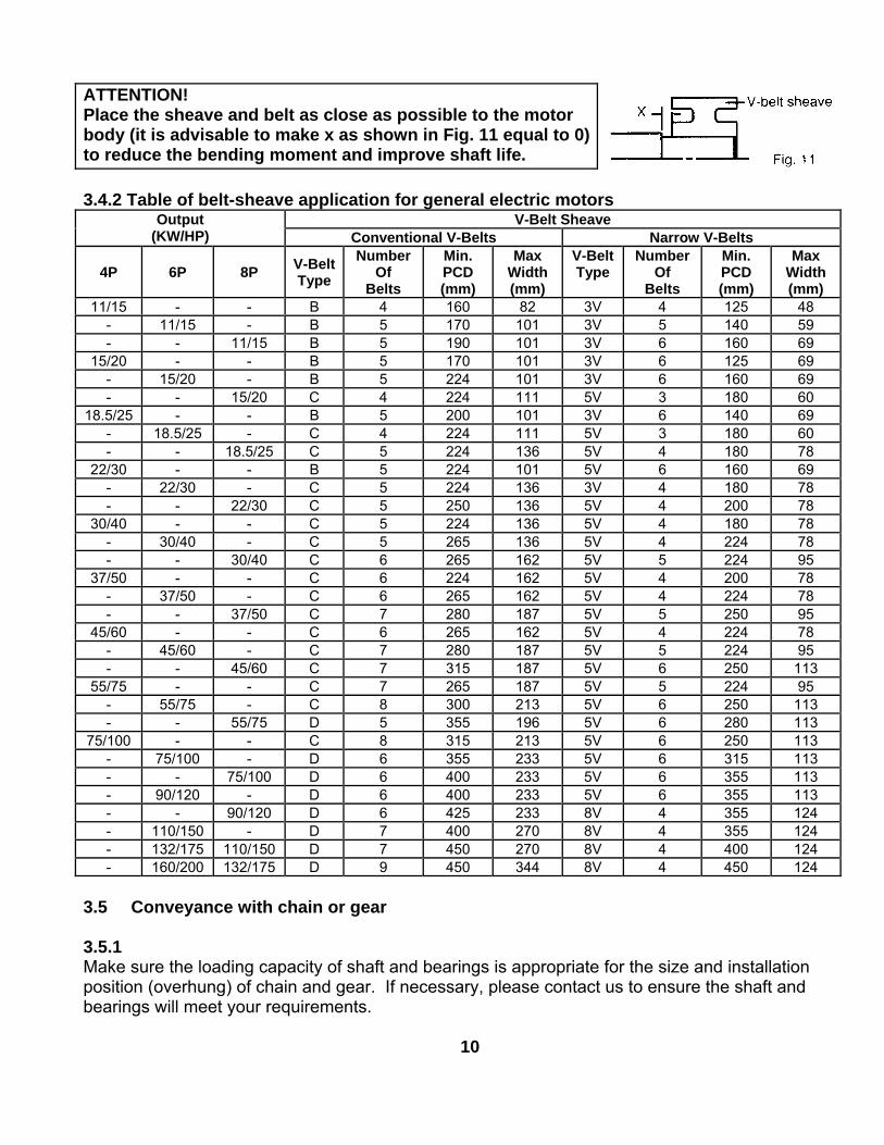
ATTENTION!Place the sheave and belt as close as possible to the motorbody (it is advisable to make x as shown in Fig. 11 equal to 0)to reduce the bending moment and improve shaft life.
3.4.2 Table of belt-sheave application for general electric motorsV-Belt SheaveOutput
(KW/HP) Conventional V-Belts Narrow V-Belts
4P 6P 8P V-BeltType
NumberOf
Belts
Min.PCD(mm)
MaxWidth(mm)
V-BeltType
NumberOf
Belts
Min.PCD(mm)
MaxWidth(mm)
11/15 - - B 4 160 82 3V 4 125 48- 11/15 - B 5 170 101 3V 5 140 59- - 11/15 B 5 190 101 3V 6 160 69
15/20 - - B 5 170 101 3V 6 125 69- 15/20 - B 5 224 101 3V 6 160 69- - 15/20 C 4 224 111 5V 3 180 60
18.5/25 - - B 5 200 101 3V 6 140 69- 18.5/25 - C 4 224 111 5V 3 180 60- - 18.5/25 C 5 224 136 5V 4 180 78
22/30 - - B 5 224 101 5V 6 160 69- 22/30 - C 5 224 136 3V 4 180 78- - 22/30 C 5 250 136 5V 4 200 78
30/40 - - C 5 224 136 5V 4 180 78- 30/40 - C 5 265 136 5V 4 224 78- - 30/40 C 6 265 162 5V 5 224 95
37/50 - - C 6 224 162 5V 4 200 78- 37/50 - C 6 265 162 5V 4 224 78- - 37/50 C 7 280 187 5V 5 250 95
45/60 - - C 6 265 162 5V 4 224 78- 45/60 - C 7 280 187 5V 5 224 95- - 45/60 C 7 315 187 5V 6 250 113
55/75 - - C 7 265 187 5V 5 224 95- 55/75 - C 8 300 213 5V 6 250 113- - 55/75 D 5 355 196 5V 6 280 113
75/100 - - C 8 315 213 5V 6 250 113- 75/100 - D 6 355 233 5V 6 315 113- - 75/100 D 6 400 233 5V 6 355 113- 90/120 - D 6 400 233 5V 6 355 113- - 90/120 D 6 425 233 8V 4 355 124- 110/150 - D 7 400 270 8V 4 355 124- 132/175 110/150 D 7 450 270 8V 4 400 124- 160/200 132/175 D 9 450 344 8V 4 450 124
3.5 Conveyance with chain or gear
3.5.1Make sure the loading capacity of shaft and bearings is appropriate for the size and installationposition (overhung) of chain and gear. If necessary, please contact us to ensure the shaft andbearings will meet your requirements.
10
3.5.2Pay close attention to ensure the parallelism of shafts.
3.5.3The teeth of couplings should be correctly and precisely matched; the force conveyancecenters should lie on the same line.
3.5.4There should be no skip, jumping, vibration or unusual noises.
ATTENTION!Do not hammer conveyance devices such as couplings, belt sheaves, chain wheels, gearsetc. onto the shaft. Conveyance devices should be fitted and removed only by means ofsuitable devices. Heat shrinking may be a better alternative to avoid damaging bearingsand components.
The exposed rotating parts should be covered to prevent accidents.
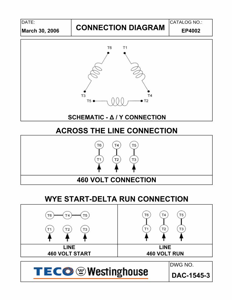
3.6 Electrical connectionsAll interconnecting wiring for controls and grounding should be in strict accordance with localrequirements such as the USA National Electrical Code and UK IEE wiring regulations. Wiring ofmotor and control, overload protection and grounding should follow the instructions of connectiondiagrams attached to the motor.
3.6.1 PowerThe rated conditions of operation for the motor are as shown on the nameplate. Within the limits,given below, of voltage and frequency variation from the nameplate values, the motor willcontinue to operate but with performance characteristics that may differ from those at ratedconditions:
±10% of rated voltage±5% of rated frequency±10% combined voltage and frequency variation so long as frequency variation isno more than ±5% of rated.
Operating the motor at voltages and frequencies outside of the above limits can result in bothunsatisfactory motor performance and damage to or failure of the motor.
3.6.2The main lead box furnished with the motor has been sized to provide adequate space for themake-up of the connections between the motor lead cables and the incoming power cables.
The bolted joints between the motor lead and the power cables must be made andinsulated in a workman-like manner following the best trade practices.
3.6.3Either fabricated motors or fan cooled cast frame, motors are all provided with grounding pads orbolts.
The motor must be grounded by proper connection to the electrical system ground.
11
3.6.4The rotation direction of the motor will be as shown by either a nameplate on the motor or theoutline drawing. The required phase rotation of the incoming power for this motor rotation mayalso be stated. If either is unknown, the correct sequence can be determined in the followingmanner: While the motor is uncoupled from the load, start the motor and observe the direction ofrotation. Allow the motor to achieve full speed before disconnecting it from the power source.Refer to the operation section of these instructions for information concerning initial start-up. Ifresulting rotation is incorrect, it can be reversed by interchanging any two (2) incoming cables.
3.6.5 Auxiliary devicesAuxiliary devices such as resistance temperature detectors, thermocouples, thermoguards, etc.,will generally terminate on terminal blocks located in the auxiliary terminal box on the motor.Other devices may terminate in their own enclosures elsewhere on the motor. Such informationcan be obtained by referring to the outline drawing. Information regarding terminal designationand the connection of auxiliary devices can be obtained from auxiliary drawings or attachednameplates.If the motor is provided with internal space heaters, the incoming voltage supplied to them mustbe exactly as shown by either a nameplate on the motor or the outline drawing for proper heateroperation.
Caution must be exercised anytime contact is made with the incoming spaceheater circuit as space heater voltage is often automatically applied when themotor is shutdown.
4. OPERATION
4.1 Examination before start4.1.1When motors are installed in good manner, ensure the wiring is according to the diagram. Also,the following points should be noted:
(a) Make sure all wiring is correct.(b) Ensure the sizes of cable wires are appropriate and all connections are well made for the
currents they will carry.(c) Ensure all connections are properly insulated for the voltage and temperature they will
experience.(d) Ensure the capacity of fuses, switches, magnetic switches and thermo relays etc. are
appropriate and the contactors are in good condition.(e) Make sure the frame and terminal box are grounded.(f) Make sure that the starting method is correct.(g) Make sure switches and starters are set at their right positions.(h) Motor heaters must be switched off when the motor is running.
4.1.2 Measurement of insulation resistance
During and immediately after measuring, the terminals must not be touched as theymay carry residual dangerous voltages. Furthermore, if power cables areconnected, make sure that the power supplies are clearly disconnected and thereare no moving parts.
12
(a) For rated voltage below 1000V, measured with a 500VDC megger.(b) For rated voltage above 1000V, measured with a 1000VDC megger.(c) In accordance with IEEE 43, clause 9.3, the following formula should be applied:
Rated voltage (v)R≥( 1000 + 1) x 10(MΩ)
(d) On a new winding, where the contaminant causing low insulation resistance is generallymoisture, drying the winding through the proper application of heat will normally increasethe insulation resistance to an acceptable level. The following are several acceptedmethods for applying heat to the winding:(1) If the motor is equipped with space heaters, they can be energized to heat the
winding.(2) Direct current (as from a welder) can be passed through the winding. The total current
should not exceed approximately 50% of rated full load current. If the motor has onlythree leads, two must be connected together to form one circuit through the winding.In this case, one phase will carry the fully applied current and each of the others, one-half each. If the motor has six leads (3 mains and 3 neutrals), the three phases shouldbe connected into one series circuit.
Ensure there is adequate guarding so live parts cannot be touched.
(3) Heated air can either blown directly into the motor or into a temporary enclosuresurrounding the motor. The source of heated air should preferably be electrical asopposed to fueled (such as kerosene) where a malfunction of the fuel burner couldresult in carbon entering the motor.
ATTENTION!Caution must be exercised, when heating the motor with any source of heat other than selfcontained space heaters, to raise the winding temperature at a gradual rate to allow anyentrapped moisture to vaporize and escape without rupturing the insulation. The entireheating cycle should extend over 15-20 hours.
Insulation resistance measurements can be made while the winding is being heated.However, they must be corrected to 40ºC for evaluation since the actual insulationresistance will decrease with increasing temperature. As an approximation for a newwinding, the insulation resistance will approximately halve for each 10ºC increase ininsulation temperature above the dew point temperature.
(e) Should the resistance fail to attain the specified value even after drying, carefulexamination should be undertaken to eliminate all other possible causes, if any.
4.1.3 Power Source(a) Ensure the capacity of the power source is sufficient.(b) Ensure the supply voltage and frequency ratings are identical to those on the nameplate.(c) Voltage variation should be confined to within ±10% of the rated value and the phase to
phase voltages should be balanced.13
4.1.4 Bearing lubrication(a) For sleeve bearing motors, the oil reservoir must be filled with oil to the correct level. On
self-lubricated bearings, the standstill oil level will be at the center of the oil gauge. Theproper oil is a rust and oxidation inhibited, turbine grade oil. Refer to the lubricationnameplate for the recommended viscosity.
(b) Motors, which are supplied with provision for flood lubrication, have an inlet orifice tometer the oil flow to the bearing. Refer to the outline drawing for these values. If thesupply pressure does not match that stated on the outline, the orifice size must beadjusted to produce the specified flow rate. The drain adapter (also provided) has a weirplate fixed to the inside of the pipe to permit the establishment of the proper oil level. Thisweir plate must be located at the bottom of the pipe and must be parallel to the plane ofthe motor feet. To ensure optimum flow, the drain line should be vented to theatmosphere.
Oil inlet temperature: Normal below 50ºCAlarm 60ºCTrip 65ºC
(c) If the motor is in storage for over three (3) months, refilling of some new oil should beundertaken before operation to prevent bearing damage due to dry friction. The oil levelshould be kept at the center of the oil gauge. If necessary, drain some oil after refilling.
(d) Motors that have been designed with anti-friction bearings for use with an oil mistlubrication system have been packed at the factory with a small amount of grease for shorttest runs. Continuous running should not be considered unless the oil mist system isinstalled and operating.
(e) Grease lubricant type(1) The bearings have been well greased at the factory before delivery. However,
regreasing is required if a significant period has elapsed between manufacture anduse or in storage
(2) Unless otherwise specified, Exxon Polyrex EM is the standard applied to TWMCmotors.
4.1.5 Cooling water for the cooler on water-cooled motorsMake sure the quality, volume and inlet temperature of cooling water for the motors are normalbefore the machine is in operation.
Water: General tower water or industrial water.Volume: Please see outline drawingInlet temperature: Normal below 30ºC
Alarm 35ºCTrip 40ºC
4.1.6ATTENTION!Make sure all locks, which fasten the movable parts of the motors during transportation,are dismantled and the shaft can rotate freely.
4.1.7ATTENTION!Ensure there are no foreign matter or tools inside the motors before starting motors.
14
4.1.8Make sure the transmission system, including belts, screws, bolts, nuts and set pins are in goodcondition.
The keys fitted to the shaft extensions are held by plastic tape only to preventthem from falling out during transportation or handling. The shaft key shall beremoved to avoid flying out, when the motor is operated prior to the couplings etc.being fitted to the shaft extension.
4.1.9Make sure the items above are examined. Test the motor running with or without load. Recordand check according to “Maintenance” at 15-minute intervals during the first three hours ofoperation. Then regular examinations should take place at longer intervals. If all goes well themotor can be classified as “in good order”.
4.2 Starting operation
4.2.1 Starting loadInitially run the motor unloaded prior to coupling to other machines. Unless otherwise specified, amotor usually starts with light load, which is then gradually increased, proportional to the squareof the speed and at last reaches 100% load at full load speed.
4.2.2 StartingToo frequent starts can be harmful to the motors. The following restrictions should be observed:
(a) Motor can be restarted should the initial start fail. Two starts are generally permissiblewhen the motor is cold.
(b) Motor can be started only once when it is at normal running temperature.(c) Should additional starts be necessary beyond the conditions stated above, the following
restrictions should be noted:(1) Let the motor cool down for 60 minutes before restarting, fully loaded.(2) Let the motor cool down for 30 minutes before restarting, unloaded.(3) Two inching starts can be regarded as one normal start.
ATTENTION!If the motor rotor fails to start turning within one or two seconds, shut off the powersupply immediately.Investigate thoroughly and take corrective action before attempting a restart.
Possible reasons for not starting are:(1) Too low a voltage at the motor terminals.(2) The load is too much for the rotor to accelerate.(3) The load is frozen up mechanically.(4) All electrical connections have not been made.(5) Single-phase power has been applied.(6) Any combination of the above.
15
4.2.3 Rotating direction(a) Most TWMC motors are bi-directional. However, when some special types, such as high
speed 2-Pole, certain large capacity motors, those with a non-reversing ratchet etc.,should rotate in one direction, please ensure the rotation is in conformity with thedirectional arrow-mark shown on the attached nameplate.
(b) To reverse a bi-directional motor, cut the power and wait until the motor stops. Theninterchange any two of the three phases.
4.2.4 Power source, Voltage, Current(a) Ensure the voltage and frequency of the power source are identical to the ratings shown
on the nameplate.(b) Voltage variation should be confined to within ±10% of the rating and the three phase
voltages should be in full balance(c) Ensure the motor phase currents, when without load, are within ±5% of the average
values.
4.2.5Frequency variation should be confined to within ±5% of the rating. The aggregate variation ofvoltage and frequency should be confined to within ±10% of the absolute value of the ratings.
4.2.5 Starting time and unusual noisesATTENTION!Starting time is longer for the motors with large inertia. However, if starting time is longerthan usual or if there is difficulty in starting, or there is abnormal noise, do not run themotor and refer to TWMC Service representative.
4.2.6 Sleeve bearing oil rings (sleeve bearing types only)As the oil ring is used to carry lubricant to sleeve bearings, frequently check to ensure the oil ringis in motion.
4.2.7 Bearing temperature riseFollowing the initial start-up, the bearing temperatures should be closely monitored. The rate ofrise in bearing temperature is more indicative of impending trouble than is the actual temperature.
ATTENTION!If the rate of rise in temperature is excessive or if the motor exhibits excessive vibration ornoise, it should be shut down immediately and a thorough investigation made as to thecause before it is operated again.
If the bearing temperature rise and motor operation appear to be normal, operation shouldcontinue until the bearing temperature stabilizes.
Recommended limits on bearing temperature are as follows:Sleeve Bearings Total measured temperature By permanently installed detector 90ºC By temporary detector on top of the bearing sleeve near the oil ring
85ºC
16
Anti-Friction Bearings Total measured temperature By permanently installed detector 100ºC By temporary detector measuring the outside of the bearing housing
95ºC
ATTENTION! (For sleeve bearing)(1) It must be noted that when operating flood lubricated sleeve bearings without outside
lubrication supplied, the bearing temperature must not be allowed to exceed 85ºC totaltemperature
(2) Under normal condition, for the self-lube bearing, the rate of temperature rise shouldbe from 11 to 14ºC for the first ten (10) minutes after starting up and approximately22ºC at thirty (30) minutes. The rate of bearing temperature rise is a function of thenatural ventilation and operating conditions.
(3) When the rate of bearing temperature rise is less than 1ºC per half-hour, the bearingtemperature is considered to be stabilized.
(4) If the total bearing temperature exceeds 95ºC, the motor should be shut downimmediately.
4.2.8 Noise and VibrationATTENTION!Any abnormal noise or vibration should be immediately investigated and corrected.Increased vibration can be indicative of a change in balance due to mechanical failure of arotor part, a stator winding problem or a change in motor alignment.
5. MAINTENANCE
5.1 Major points in regular inspections and maintenance.
For safety, maintenance and repairs must only be carried out by properly trainedpersonnel.
Some testing, such as insulation resistance, usually requires the motor to bestopped and isolated from power supplie(s).
Routine inspection and maintenance are usually performed by looking, listening, smelling andsimple meters.
High temperature may arise under operating conditions on the motor surfaces, sothat touching should be prevented or avoided. Keep away from moving and liveparts. Unless deemed necessary, do not remove guards whilst assessing themotor.
Timely replacement of worn parts can assure longevity and prevent breakdown.
Routine inspection and regular inspection and maintenance are important in preventingbreakdown and lengthening service life.
17
Owing to the varied time and circumstances, motors are used, it is difficult to set the items andperiods for regular inspection and maintenance. However, as a guide it is recommended to beperformed periodically according to factory maintenance program. Generally, the inspectionscope determined by the following factors:
(a) Ambient temperature.(b) Starting and stopping frequency.(c) Troublesome parts usually affecting motor functions.(d) Easily abraded parts.(e) The important position of motor in the operational system of a factory should be duly
recognized. Therefore, its health and wellbeing should be fully protected especially whenit is operating in severe conditions.
5.2 Motor windings:(a) Measurement of insulation resistance and standards to determine quality of insulation
resistance, please refer to measures stated in 3.1.2 “Measurement of insulationresistance”.
(b) Inspection of coil-ends:(1) Grease and dust accumulated on coils may cause insulation deterioration and poor
cooling effect.(2) Moisture must not accumulate. Keep coils warm when motor is not in use if moisture
can be seen.(3) Discoloring. This is mainly caused by overheating.
(c) Ensure no untoward change of wedges from original position.(d) Ensure the binding at the coil end is in its normal position.
5.3 Clean the interior of the motor:(a) After a motor is in operation for some time, accumulation of dust, carbon powder and
grease etc., on the inside is unavoidable, and may cause damage. Regular cleaning andexamination is necessary to assure top performance.
(b) Points to note during cleaning:(1) If using compressed air or blower:
(a) Compressed air should be free of moisture.(b) Maintain air pressure at 4 kg/cm², since high pressure can cause damage to coils.
(2) VacuumVacuum cleaning can be used, both before and after other methods of cleaning, toremove loose dirt and debris. It is a very effective way to remove loose surfacecontamination from the winding without scattering. Vacuum cleaning tools should benon-metallic to avoid any damage to thee winding insulation
(3) WipingSurface contamination on the winding can be removed by wiping using a soft, lint-freewiping material. If the contamination is oily, the wiping material can be moistened(not dripping wet) with a safety type petroleum solvent. In hazardous locations, asolvent such as inhibited methyl chloroform may be used, but must be used sparinglyand immediately removed. While this solvent is non-flammable under ordinaryconditions, it is toxic and proper health and safety precautions should be followedwhile using it.
18
ATTENTION!Solvents of nay type should never be used on windings provided with abrasion protection.Abrasion protection is a gray, rubber-like coating applied to the winding end-turns.
Adequate ventilation must always be provided in any area where solvents arebeing used to avoid the danger of fire, explosion or health hazards. In confinedareas (such as pits) each operator should be provided with an airline respirator, ahose mask or a self-contained breathing apparatus. Operators should weargoggles, aprons and suitable gloves. Solvents and their vapors should never beexposed to open flames or sparks and should always be stored in approved safetycontainers.
(4) Keep core ducts completely clean. The difference in temperature rise could bearound 10°C before and after cleaning
5.4 Clean the exterior of the motor:(a) On open ventilated motors, screens and louvers over the inlet air openings should not be
allowed to accumulate any build-up of dirt, lint, etc. that could restrict free air movement.
ATTENTION!Screens and louvers should never be cleaned or disturbed while the motor is in operationbecause any dislodged dirt or debris can be drawn directly into the motor.
(b) If the motor is equipped with air filters, they should be replaced (disposable type) orcleaned and reconditioned (permanent type) at a frequency that is dictated by conditions.It is better to replace or recondition filters too often than not often enough.
(c) Totally enclosed air to air cooled and totally enclosed fan cooled motors require specialcleaning considerations. The external fan must be cleaned thoroughly since any dirtbuild-up not removed can lead to unbalance and vibration. All of the tubes of the air-to-air heat exchanger should be cleaned using a suitable tube brush having synthetic fiberbristles (not wire of any type).
5.5 Maintenance of anti-friction bearings
5.5.1 Frequency of re-lubrication:The life of grease varies greatly as a result of types of model, revolution speed, temperature,operational conditions etc. It is, therefore, impossible to be precise about replenishment intervals.However, for normal direct coupling transmission, the periods shown as Table 1 may be used asa guide.
Remarks:(a) The periods shown in Table 1 should be halved where bearings are used for belt drive
and/or in dirty or high ambient temperature or high humidity environments.(b) Please refer to the lubrication nameplate, if attached to the motor.(c) For bearing numbers outside the range of Table 1, please contact TWMC
19
(d) If the periods referred to in Table 1 for drive-end bearing and opposite drive-end aredifferent, for the convenience of maintenance operation, please take the shorter one therequired grease replenishment period of these bearings.
5.5.1 Kinds of grease:Exxon Polyrex EM (polyurea base grease) will be used for all models with open bearings. Pleasecheck and follow lubrication nameplate for any special grease used in bearings. Please usidentical grease or its equivalents when maintaining motor.
ATTENTION!Do not mix different kinds of grease.Mixing grease with different type of thickeners may destroy its composition and physicalproperties. Even if the thickeners are of the same type, possible differences in theadditive may cause detrimental effects.
5.5.2 Grease quantityThe amount of grease per replenishment depends on the type, size and construction of thebearings. The maximum amount of replenishment for each bearing is shown in Table 2.
5.5.3 Re-greasing
If re-lubrication is to be performed when the motor is running, stay clear of rotatingparts.
It is advisable to re-grease when the motor is running to allow the new grease to be evenlydistributed inside the bearing.Before re-greasing, the inlet fitting should be thoroughly cleaned to prevent any accumulated dirtfrom being carried into the bearing with the new grease. The outlet of grease drainage should beopened to allow the proper venting of old grease.
Use a grease gun to pump grease through grease nipple into the bearings. After re-greasing,operate the motor for 10-30 minutes to allow any excess grease to vent out.
20
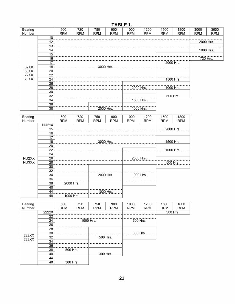
TABLE 1.BearingNumber
600RPM
720RPM
750RPM
900RPM
1000RPM
1200RPM
1500RPM
1800RPM
3000RPM
3600RPM
1012 2000 Hrs.1314 1000 Hrs.1516 720 Hrs.17 2000 Hrs.18 3000 Hrs.202224 1500 Hrs.2628 2000 Hrs. 1000 Hrs.3032 500 Hrs.34 1500 Hrs.36
62XX63XX72XX73XX
38 2000 Hrs. 1000 Hrs.
BearingNumber
600RPM
720RPM
750RPM
900RPM
1000RPM
1200RPM
1500RPM
1800RPM
NU21415 2000 Hrs.161718 3000 Hrs. 1500 Hrs.2022 1000 Hrs.2426 2000 Hrs.28 500 Hrs.303234 2000 Hrs. 1000 Hrs.3638 2000 Hrs.4044 1000 Hrs.
NU2XXNU3XX
48 1000 Hrs.
BearingNumber
600RPM
720RPM
750RPM
900RPM
1000RPM
1200RPM
1500RPM
1800RPM
22220 300 Hrs.2224 1000 Hrs. 500 Hrs.262830 300 Hrs.32 500 Hrs.343638 500 Hrs.40 300 Hrs.44
222XX223XX
48 300 Hrs.
21
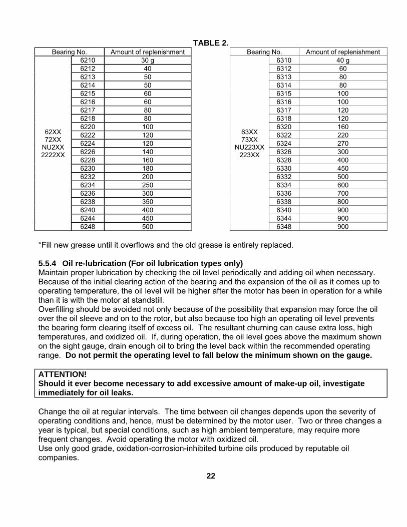
TABLE 2.Bearing No. Amount of replenishment Bearing No. Amount of replenishment
6210 30 g 6310 40 g6212 40 6312 606213 50 6313 806214 50 6314 806215 60 6315 1006216 60 6316 1006217 80 6317 1206218 80 6318 1206220 100 6320 1606222 120 6322 2206224 120 6324 2706226 140 6326 3006228 160 6328 4006230 180 6330 4506232 200 6332 5006234 250 6334 6006236 300 6336 7006238 350 6338 8006240 400 6340 9006244 450 6344 900
62XX72XX
NU2XX2222XX
6248 500
63XX73XX
NU223XX223XX
6348 900
*Fill new grease until it overflows and the old grease is entirely replaced.
5.5.4 Oil re-lubrication (For oil lubrication types only)Maintain proper lubrication by checking the oil level periodically and adding oil when necessary.Because of the initial clearing action of the bearing and the expansion of the oil as it comes up tooperating temperature, the oil level will be higher after the motor has been in operation for a whilethan it is with the motor at standstill.Overfilling should be avoided not only because of the possibility that expansion may force the oilover the oil sleeve and on to the rotor, but also because too high an operating oil level preventsthe bearing form clearing itself of excess oil. The resultant churning can cause extra loss, hightemperatures, and oxidized oil. If, during operation, the oil level goes above the maximum shownon the sight gauge, drain enough oil to bring the level back within the recommended operatingrange. Do not permit the operating level to fall below the minimum shown on the gauge.
ATTENTION!Should it ever become necessary to add excessive amount of make-up oil, investigateimmediately for oil leaks.
Change the oil at regular intervals. The time between oil changes depends upon the severity ofoperating conditions and, hence, must be determined by the motor user. Two or three changes ayear is typical, but special conditions, such as high ambient temperature, may require morefrequent changes. Avoid operating the motor with oxidized oil.Use only good grade, oxidation-corrosion-inhibited turbine oils produced by reputable oilcompanies.
22
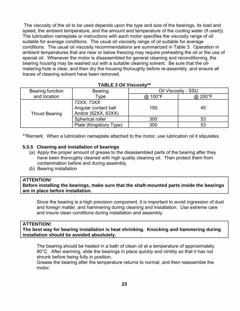
The viscosity of the oil to be used depends upon the type and size of the bearings, its load andspeed, the ambient temperature, and the amount and temperature of the cooling water (if used)).The lubrication nameplate or instructions with each motor specifies the viscosity range of oilsuitable for average conditions. The usual oil viscosity range of oil suitable for averageconditions. The usual oil viscosity recommendations are summarized in Table 3. Operation inambient temperatures that are near or below freezing may require preheating the oil or the use ofspecial oil. Whenever the motor is disassembled for general cleaning and reconditioning, thebearing housing may be washed out with a suitable cleaning solvent. Be sure that the oil-metering hole is clear, and then dry the housing thoroughly before re-assembly, and ensure alltraces of cleaning solvent have been removed.
TABLE 3 Oil Viscosity**Oil Viscosity - SSUBearing function
and locationBearing
Type @ 100°F @ 200°F72XX, 73XXAngular contact ballAnd/or (62XX, 63XX)
150 45
Spherical roller 300 53Thrust Bearing
Plate (Kingsbury Type) 300 53
**Remark: When a lubrication nameplate attached to the motor, use lubrication oil it stipulates.
5.5.5 Cleaning and installation of bearings(a) Apply the proper amount of grease to the disassembled parts of the bearing after they
have been thoroughly cleaned with high quality cleaning oil. Then protect them fromcontamination before and during assembly.
(b) Bearing installation
ATTENTION!Before installing the bearings, make sure that the shaft-mounted parts inside the bearingsare in place before installation.
Since the bearing is a high precision component, it is important to avoid ingression of dustand foreign matter, and hammering during cleaning and installation. Use extreme careand insure clean conditions during installation and assembly.
ATTENTION!The best way for bearing installation is heat shrinking. Knocking and hammering duringinstallation should be avoided absolutely.
The bearing should be heated in a bath of clean oil at a temperature of approximately80°C. After warming, slide the bearings in place quickly and nimbly so that it has notshrunk before being fully in position.Grease the bearing after the temperature returns to normal, and then reassemble themotor.
23
5.6 Maintenance of sleeve bearings
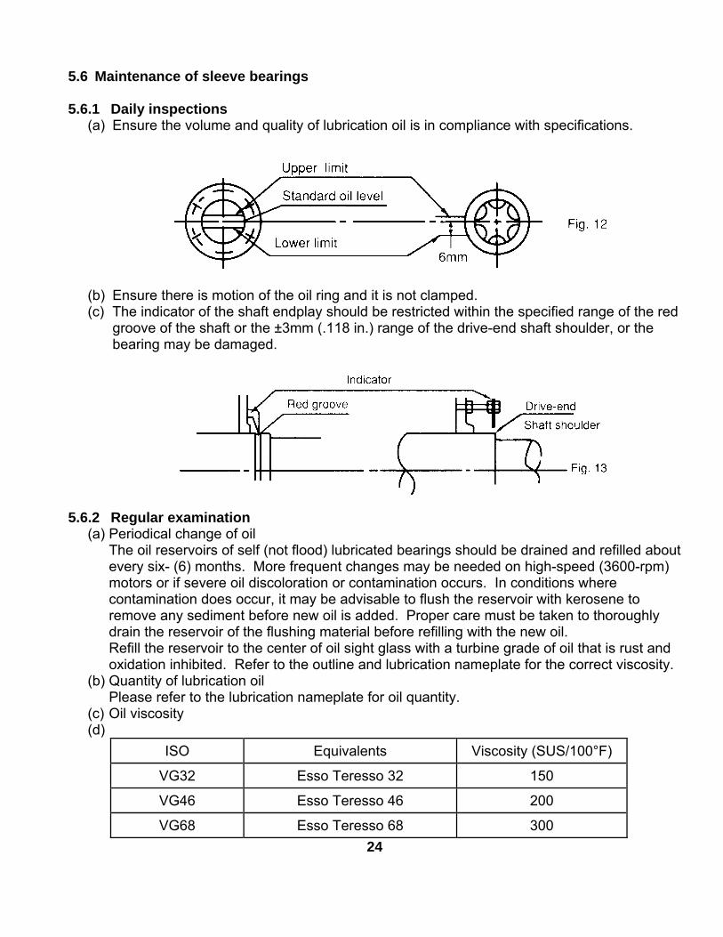
5.6.1 Daily inspections(a) Ensure the volume and quality of lubrication oil is in compliance with specifications.
(b) Ensure there is motion of the oil ring and it is not clamped.(c) The indicator of the shaft endplay should be restricted within the specified range of the red
groove of the shaft or the ±3mm (.118 in.) range of the drive-end shaft shoulder, or thebearing may be damaged.
5.6.2 Regular examination(a) Periodical change of oil
The oil reservoirs of self (not flood) lubricated bearings should be drained and refilled aboutevery six- (6) months. More frequent changes may be needed on high-speed (3600-rpm)motors or if severe oil discoloration or contamination occurs. In conditions wherecontamination does occur, it may be advisable to flush the reservoir with kerosene toremove any sediment before new oil is added. Proper care must be taken to thoroughlydrain the reservoir of the flushing material before refilling with the new oil.Refill the reservoir to the center of oil sight glass with a turbine grade of oil that is rust andoxidation inhibited. Refer to the outline and lubrication nameplate for the correct viscosity.
(b) Quantity of lubrication oilPlease refer to the lubrication nameplate for oil quantity.
(c) Oil viscosity(d)
ISO Equivalents Viscosity (SUS/100°F)
VG32 Esso Teresso 32 150
VG46 Esso Teresso 46 200
VG68 Esso Teresso 68 30024
5.6.3 Disassembly
Prior to disassembling, ensure the power supplies are disconnected and thereare no moving parts.
The bearing sleeve is of the spherically seated, self-aligning type. The opposite drive endbearing is normally insulated for larger motors (or when specified). On some motors, theinsulation is bonded to the spherical seat of the bearing housing.
ATTENTION!Extreme care must be exercised in removing the bearing sleeve from the insulated supportto avoid damaging this insulation.
The following is the recommended procedure for removing the bearing sleeve:
(a) Remove the oil drain plug in the housing bottom and drain the oil sump.
(b) Remove all instrumentation sensors that are in contact with the bearing sleeve. Thesewould include resistance temperature detectors, thermocouples, thermometers, etc.
(c) Remove the socket head bolts holding the bearing cap and the inner air seal. The endcover plate must also be removed if the non-drive end bearing is being disassembled.Remove the bearing cap and top half of the inner air seal. Place them on a clean, drysurface to avoid damage to the parting surfaces.
(d) Remove the top half of the bearing sleeve using suitable eyebolts in the tapped holesprovided. Lift the bearing top straight up and avoid any contact with the shoulders of theshaft journals that might damage the thrust faces of the bearing. Place on a clean, drysurface taking care to prevent damage to either the parting surfaces or the locating pinsthat are captive n the top bearing half.
(e) Remove the screws at the partings in the oil ring and dismantle the ring by gently tappingthe dowel pin ends with a soft face mallet. Remove the ring halves and immediatelyreassemble them to avoid any mix up I parts or damage to the surfaces at the partings.
(f) Pull up on the garter spring that surrounds the floating labyrinth seal and carefully slip outthe top half. Rotate the garter spring until the lock is visible. Twist counter-clockwise todisengage the lock, remove the garter spring then rotate the lower half of the seal out ofthe groove in the bearing housing. Note the condition of these floating labyrinth seals. Ifthey are cracked or chipped, they must be replaced. Do not attempt to reuse a damagedseal.
(g) To remove the bottom bearing half, the shaft must be raised a slight amount to relievepressure on the bearing. On the drive end, jacking or lifting the shaft extension will relievethe pressure on the bearing for removal. Protect the shaft. On the non-drive, jacking orlifting can be done using bolts threaded into the tapped holes provided in the shaft end.
25
(h) Roll the bottom bearing half to the top of the shaft journal and then lift it using suitableeyebolts threaded into the holes provided. Again avoid any contact with the shaftshoulders that could damage the bearing thrust faces. Place the lower bearing half on aclean, dry surface to protect the parting surfaces.
Use extreme care when rolling out the lower bearing half. Keep the hands andfingers well clear of any position where they might be caught by the bearing half ifit were accidentally released and rotated back to its bottom position. Seriouspersonal injury could result.
(i) Protect the shaft journal by wrapping it with clean, heavy paper or cardboard.
5.6.4 Re-assemblyBearing re-assembly is basically a reverse of the disassembly procedures outlined above, withthe following suggestions:
(a) The interior of the bearing housing should be cleaned and then flushed with clean oil orkerosene.
(b) The bearing halves and the shaft journal should be wiped clean using lint-free cloth soakedwith clean oil.
(c) All parts should be carefully inspected for nicks, scratches, etc., in any contract surfaces.Such imperfections should be removed by an appropriate method such as stoning,scraping, filling, etc., followed by thorough cleaning.
(d) Before installing the floating labyrinth seal halves, observe their condition. Do not attemptto use a cracked or chipped seal. The bottom half seal has a set of drilled holes in its sideface. These must be place at the bottom toward the inside of the bearing so thataccumulating oil may drain back into the housing.
(e) Put a bead of Curil-T around the seal half outside diameter on both sides adjacent to thegarter spring groove. This will prevent oil by-passing the seal around its outside.
(f) Place the bottom seal half on top of the shaft and roll it into position. Install the top half andinsert the garter spring pulling up on both ends to permit engaging the lock. Run a bead ofCuril-T around the outside diameter on both sides adjacent to the garter spring groove onthis half also.
(g) Carefully reassemble the two oil ring halves. Inspect the dowel pins for burrs andstraightness and make any corrections required. Do not force the ring halves together.Excessive force may alter the roundness or flatness of the oil ring, which can change its oildelivery performance.
(h) Some of the pipe plugs in the housing are metric thread type. These are identified asthose, which have a copper, lead, or similar material washer. If these plugs are removed,
26
be careful not to lose the washers. Before re-assembly, inspect the washers and replacethem as required.
(i) Before installing the bearing cap, observe the position of the floating labyrinth seal. The“tab” must be on top to engage the pocket. Failure to position the seal properly will resultin damage when the cap is assembled.
ATTENTION!(1) Curil-T is the only approved compound for use in the assembly of the bearings on this
motor. Other products may harden and impede the operation.(2) During the re-assembly of the bearing parts, a thin layer of Curil-T should be applied to
all gaskets and machined interface surfaces. This suggestion does not apply to themachined surfaces of the bearing liner halves.
(3) When seating the bearing shell, apply a thin layer of lube oil at the spherical surface ofthe liner. Slowly roll the lower bearing liner into the bearing housing making sure thatthe splinted surface of the liner and the housing are flush. Gradually lower the shaftonto the bearing. The weight of he shaft will help rotate the bearing liner so that thebabbitt surface of the liner will match the slope of the journal. Sometimes it is requiredto use a rubber mallet to tap lightly on the bearing housing while slowly rolling theshaft to help this seating operation.
5.7 Maintenance of slip ring (For Wound Rotor Motors only)
Ensure motor is disconnected from power supplies and there are no accessiblemoving parts before maintenance operation.
5.7.1 Adjustment of carbon brush(a) Brush pressure for normal operation:
Electro-graphite brush…0.2~0.25 kg/cm²When frequent vibrations are evident or the brush is small (area below 0.5 cm²), thepressure should be greater than as shown.
(b) Adjustment of brush pressure:The brush pressure should be adjusted to keep normal operation as it wears. The brush pressure may be reduced after use, so it is necessary to re-adjust. For
adjustment, please turn adjusting screw, pressure adjusting pin or pressure adjustingplate as shown in Fig. 14 to obtain the correct tension (=0.23 x brush cross sectionalarea in cm²) ±10% kg.
(c) Brush pressure need not be adjusted if constant force spring is used as shown in Fig. 15and Fig. 16.
27
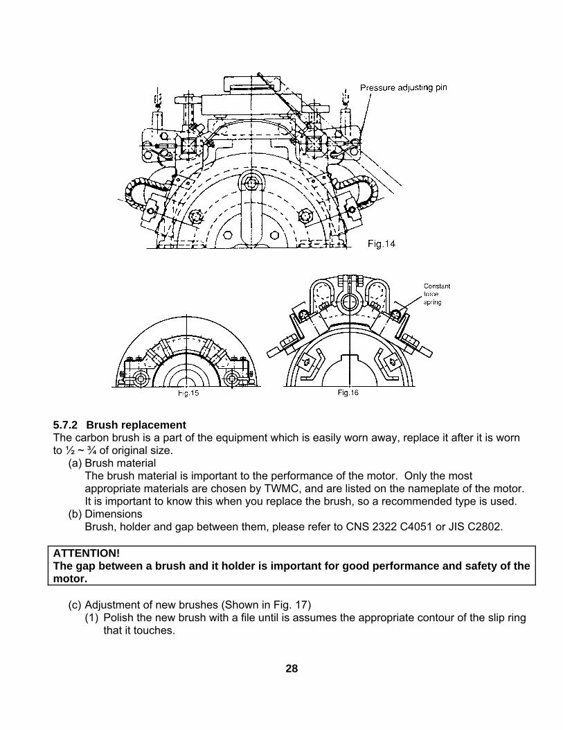
5.7.2 Brush replacementThe carbon brush is a part of the equipment which is easily worn away, replace it after it is wornto ½ ~ ¾ of original size.
(a) Brush materialThe brush material is important to the performance of the motor. Only the mostappropriate materials are chosen by TWMC, and are listed on the nameplate of the motor.It is important to know this when you replace the brush, so a recommended type is used.
(b) DimensionsBrush, holder and gap between them, please refer to CNS 2322 C4051 or JIS C2802.
ATTENTION!The gap between a brush and it holder is important for good performance and safety of themotor.
(c) Adjustment of new brushes (Shown in Fig. 17)(1) Polish the new brush with a file until is assumes the appropriate contour of the slip ring
that it touches.
28
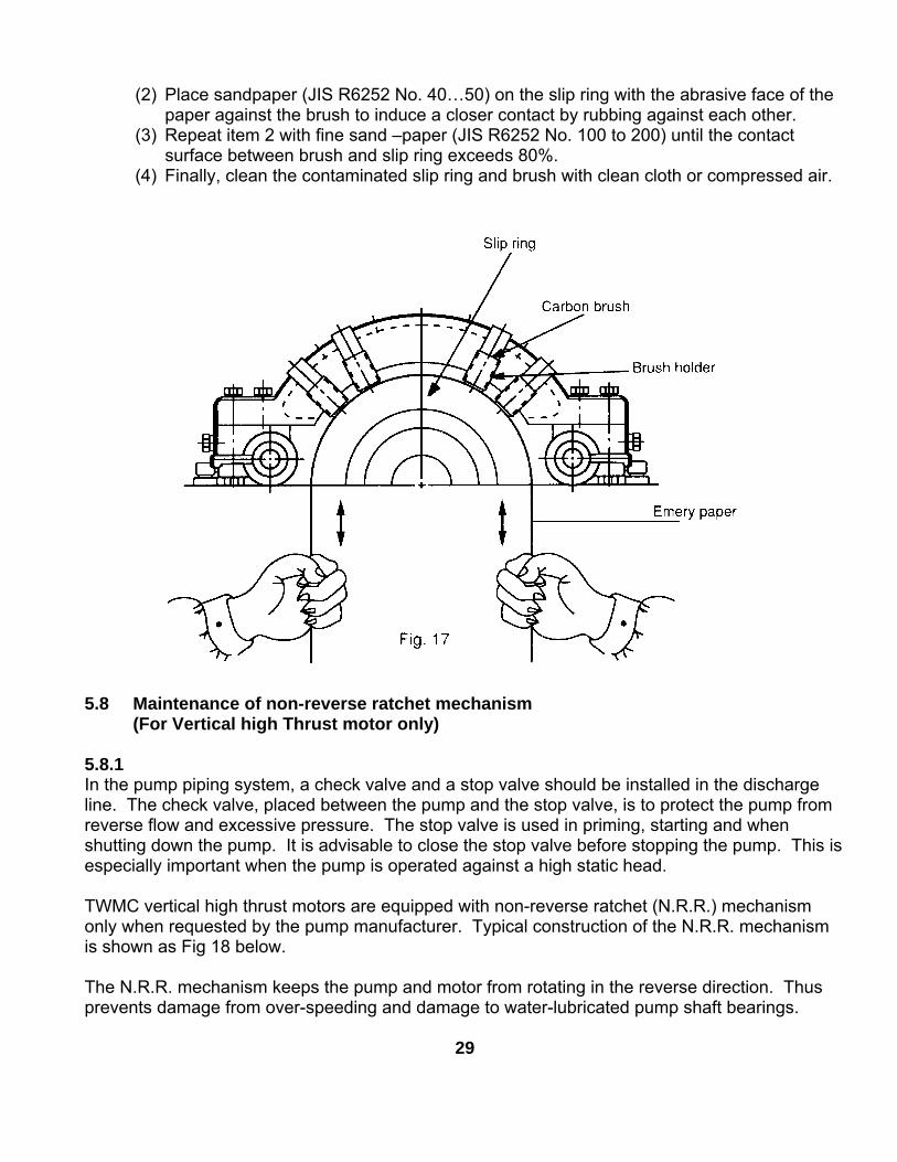
(2) Place sandpaper (JIS R6252 No. 40…50) on the slip ring with the abrasive face of thepaper against the brush to induce a closer contact by rubbing against each other.
(3) Repeat item 2 with fine sand –paper (JIS R6252 No. 100 to 200) until the contactsurface between brush and slip ring exceeds 80%.
(4) Finally, clean the contaminated slip ring and brush with clean cloth or compressed air.
5.8 Maintenance of non-reverse ratchet mechanism(For Vertical high Thrust motor only)
5.8.1In the pump piping system, a check valve and a stop valve should be installed in the dischargeline. The check valve, placed between the pump and the stop valve, is to protect the pump fromreverse flow and excessive pressure. The stop valve is used in priming, starting and whenshutting down the pump. It is advisable to close the stop valve before stopping the pump. This isespecially important when the pump is operated against a high static head.
TWMC vertical high thrust motors are equipped with non-reverse ratchet (N.R.R.) mechanismonly when requested by the pump manufacturer. Typical construction of the N.R.R. mechanismis shown as Fig 18 below.
The N.R.R. mechanism keeps the pump and motor from rotating in the reverse direction. Thusprevents damage from over-speeding and damage to water-lubricated pump shaft bearings.
29
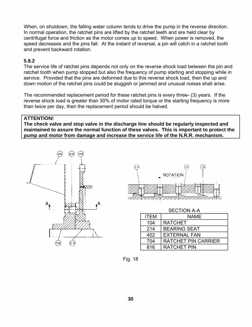
When, on shutdown, the falling water column tends to drive the pump in the reverse direction.In normal operation, the ratchet pins are lifted by the ratchet teeth and are held clear bycentrifugal force and friction as the motor comes up to speed. When power is removed, thespeed decreases and the pins fall. At the instant of reversal, a pin will catch in a ratchet toothand prevent backward rotation.
5.8.2The service life of ratchet pins depends not only on the reverse shock load between the pin andratchet tooth when pump stopped but also the frequency of pump starting and stopping while inservice. Provided that the pins are deformed due to this reverse shock load, then the up anddown motion of the ratchet pins could be sluggish or jammed and unusual noises shall arise.
The recommended replacement period for these ratchet pins is every three- (3) years. If thereverse shock load is greater than 30% of motor rated torque or the starting frequency is morethan twice per day, then the replacement period should be halved.
ATTENTION!The check valve and stop valve in the discharge line should be regularly inspected andmaintained to assure the normal function of these valves. This is important to protect thepump and motor from damage and increase the service life of the N.R.R. mechanism.
SECTION A-AITEM NAME104 RATCHET214 BEARING SEAT402 EXTERNAL FAN704 RATCHET PIN CARRIER816 RATCHET PIN
Fig. 18
30
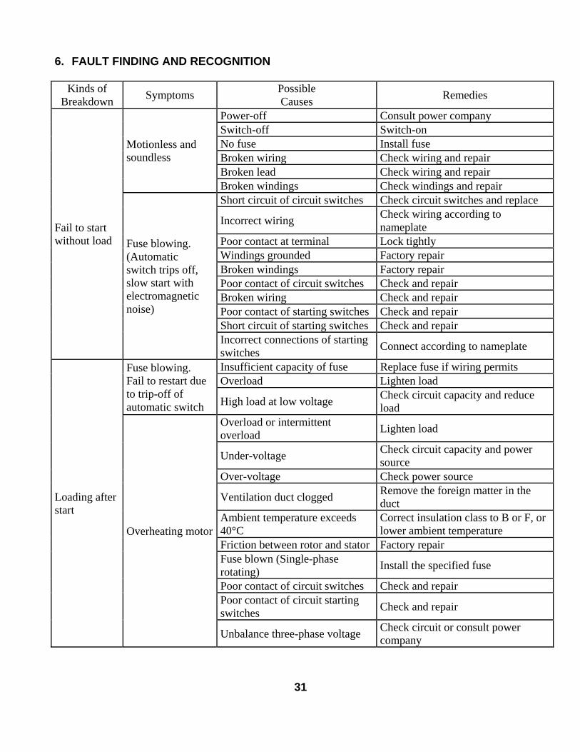
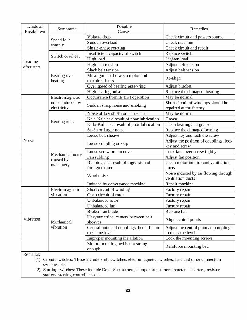
6. FAULT FINDING AND RECOGNITION
Kinds ofBreakdown Symptoms Possible
Causes Remedies
Power-off Consult power companySwitch-off Switch-onNo fuse Install fuseBroken wiring Check wiring and repairBroken lead Check wiring and repair
Motionless andsoundless
Broken windings Check windings and repairShort circuit of circuit switches Check circuit switches and replace
Incorrect wiring Check wiring according tonameplate
Poor contact at terminal Lock tightlyWindings grounded Factory repairBroken windings Factory repairPoor contact of circuit switches Check and repairBroken wiring Check and repairPoor contact of starting switches Check and repairShort circuit of starting switches Check and repair
Fail to startwithout load Fuse blowing.
(Automaticswitch trips off,slow start withelectromagneticnoise)
Incorrect connections of startingswitches Connect according to nameplate
Insufficient capacity of fuse Replace fuse if wiring permitsOverload Lighten load
Fuse blowing.Fail to restart dueto trip-off ofautomatic switch High load at low voltage Check circuit capacity and reduce
loadOverload or intermittentoverload Lighten load
Under-voltage Check circuit capacity and powersource
Over-voltage Check power source
Ventilation duct clogged Remove the foreign matter in theduct
Ambient temperature exceeds40°C
Correct insulation class to B or F, orlower ambient temperature
Friction between rotor and stator Factory repairFuse blown (Single-phaserotating) Install the specified fuse
Poor contact of circuit switches Check and repairPoor contact of circuit startingswitches Check and repair
Loading afterstart
Overheating motor
Unbalance three-phase voltage Check circuit or consult powercompany
31
Kinds ofBreakdown Symptoms Possible
Causes Remedies
Voltage drop Check circuit and powers sourceSudden overload Check machineSpeed falls
sharplySingle-phase rotating Check circuit and repairInsufficient capacity of switch Replace switchSwitch overheat High load Lighten loadHigh belt tension Adjust belt tensionSlack belt tension Adjust belt tensionMisalignment between motor andmachine shafts Re-align
Over speed of bearing outer-ring Adjust bracket
Loadingafter start
Bearing over-heating
High bearing noise Replace the damaged bearingOccurrence from its first operation May be normalElectromagnetic
noise induced byelectricity Sudden sharp noise and smoking Short circuit of windings should be
repaired at the factoryNoise of low shishi or Thru-Thru May be normalKala-Kala as a result of poor lubrication GreaseKulo-Kulo as a result of poor lubrication Clean bearing and greaseBearing noise
Sa-Sa or larger noise Replace the damaged bearingLoose belt sheave Adjust key and lock the screw
Loose coupling or skip Adjust the position of couplings, lockkey and screw
Loose screw on fan cover Lock fan cover screw tightlyFan rubbing Adjust fan positionRubbing as a result of ingression offoreign matter
Clean motor interior and ventilationducts
Wind noise Noise induced by air flowing throughventilation ducts
Noise
Mechanical noisecaused bymachinery
Induced by conveyance machine Repair machineShort circuit of winding Factory repairElectromagnetic
vibration Open circuit of rotor Factory repairUnbalanced rotor Factory repairUnbalanced fan Factory repairBroken fan blade Replace fanUnsymmetrical centers between beltsheaves Align central points
Central points of couplings do not lie onthe same level
Adjust the central points of couplingsto the same level
Improper mounting installation Lock the mounting screws
VibrationMechanicalvibration
Motor mounting bed is not strongenough Reinforce mounting bed
Remarks:(1) Circuit switches: These include knife switches, electromagnetic switches, fuse and other connection
switches etc.(2) Starting switches: These include Delta-Star starters, compensate starters, reactance starters, resistor
starters, starting controller’s etc.
32


