Download - Yuken A series Single Piston pump

A
1 2 5 10 20 50 100 200 300
Geometric DisplacementMaximum Operating Pressure
MPa (PSI)Pump Type Catalogue No.
3 cm /rev
cu. in./rev.1 .2 .5 1 2 5 10 15
"AR" Series Variable Displacement Piston Pumps 16 (2320)
21 (3050)
21 (3050)
28 (4060)
28 (4060)
31 (4500)
28 (4060)
16 (2320)
"AH" Series Variable Displacement Piston Pumps
Single Pumps
Double Pumps
Variable / Fixed Double Pumps
"A"
Serie
s V
aria
ble
Dis
plac
emen
t Pis
ton
Pum
ps
Pub. EC-0106
Pub. EC-0105
Pub. EC-0104
Inboard Pump (Driven End)
Inboard Pump (Driven End)
Outboard Pump
Outboard Pump
AR16AR22
A10A16
A22
A37A56
A70A90
A145
A16A16 A22
A22 A37A37 A56
A56A70 A90 A145
A16 A22 A37 A56 A70
RV2R1 RV2R2
AH16AH37
AH56
A90 A145
VARIABLE DISPLACEMENT PISTON PUMPS

PISTON PUMPS
1.
2.
1.
∗
12
Specifications
1
∗1
∗
A16-∗-R-01-∗-∗-K-32∗A22-∗-R-01-∗-∗-K-32∗A37-∗-R-01-∗-∗-K-32∗A56-∗-R-01-∗-∗-K-32∗
A10-FR01B-12∗A10-FR01C/H-12∗
A70-∗R01∗S-60∗A90-∗R01∗S-60∗A145-∗R01∗S-60∗
Geometric Displacement
3 cm /rev (cu. in. /rev)
Minimum Adj. Flow
3 cm /rev (cu. in. /rev) Rated Intermittent Max. Min. Flange
Mtg.Foot Mtg.
Model Numbers
Operating Pres. MPa (PSI)
Shaft Speed Range r/min
Approx. Mass kg (lbs.)
5.1 (11.2) 8.5 (18.7) 16.5 (36.4) 16.5 (36.4) 28.0 (61.7) 35.0 (77.2) 58.5 (129) 72.5 (160) 92.5 (204)
18.7 (41.2) 18.7 (41.2) 32.3 (71.2) 39.3 (86.7) 70.5 (155) 93 (205)
117.5 (259)
600 600 600 600 600 600 600
1800 1800 1800 1800 1800 1800 1800
600180021 (3050)
21 (3050) 16 (2320) 21 (3050) 21 (3050) 28 (4060) 28 (4060) 28 (4060)
16 (2320)
16 (2320) 16 (2320) 16 (2320) 16 (2320) 25 (3630) 25 (3630) 25 (3630)
2 (.122)
4 (.244) 6 (.366) 10 (.610) 12 (.732) 30 (1.83) 56 (3.42) 83 (5.06)
10.0 (.610)
15.8 (.964) 22.2 (1.355) 36.9 (2.25) 56.2 (3.43) 70.0 (4.27) 91.0 (5.55) 145 (8.85)
M
O
0
1/5 of One Cycle
20 MPa (2900) {27 MPa (3920)}
21 MPa (3050 PSI) {28 MPa (4060 PSI)}
Max.
Pres
sure
Out
put
Flow
(Max. 5s)
One Cycle Time
"A" Series Piston Pumps Variable Displacement-Single Pumps
Pressure Compensator Type A10 / A16 / A22 / A37 / A56 / A70 / A90 / A145
Specifications
Graphic Symbol
Whenever setting pressure, make sure the full cut-off pressure never exceeds the maximum intermittent pressure.
Care should be taken in cases of used at a higher pressure than the rated pressure, because operating terms may be restricted. For example, if used as per maximum illustrated operating conditions, intermittent time at maximum flow is restricted to under 1/5 of one cycle time and under 6 seconds simultaneously. Conditions may vary according to the actual working pressure and delivery (inclination angle of the swash plate). Consult factory or Yuken sales representative for further information.
Applicable only for "A70/90/145"
www.as-hydraulic.com
PISTON PUMPS
3.
1. 4.
2.
1
2
1
4
A
3
3
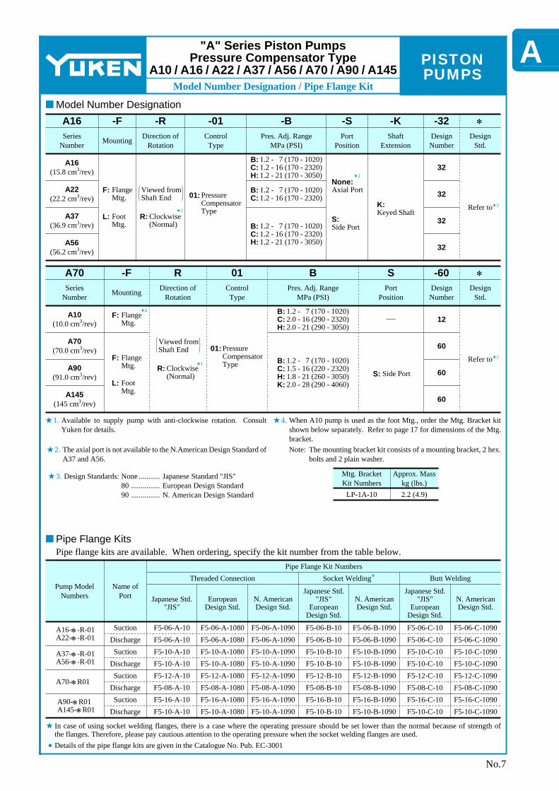
Model Number Designation / Pipe Flange Kit
Series Number
A16 3 (15.8 cm /rev)
A22 3 (22.2 cm /rev)
A37 3 (36.9 cm /rev)
A56 3 (56.2 cm /rev)
Mounting
F: Flange Mtg.
L: Foot Mtg.
Direction of Rotation
Viewed from Shaft End
R: Clockwise(Normal)
Pres. Adj. Range MPa (PSI)
Control Type
Port Position
Shaft Extension
Design Std.
Refer to
Design Number
32
32
32
32
K:Keyed Shaft
None:Axial Port
S:Side Port
01: Pressure Compensator Type
B: C: H:
1.2 - 7 (170 - 1020) 1.2 - 16 (170 - 2320) 1.2 - 21 (170 - 3050)
B: C:
1.2 - 7 (170 - 1020) 1.2 - 16 (170 - 2320)
B: C: H:
1.2 - 7 (170 - 1020) 1.2 - 16 (170 - 2320) 1.2 - 21 (170 - 3050)
∗-32-K-S-B-01-R-FA16
Series Number
A10 3 (10.0 cm /rev)
A70 3 (70.0 cm /rev)
A90 3 (91.0 cm /rev)
A145 3 (145 cm /rev)
Mounting
F: Flange Mtg.
L: Foot Mtg.
Direction of Rotation
Viewed from Shaft End
R: Clockwise(Normal)
Pres. Adj. Range MPa (PSI)
Control Type
Port Position
Design Std.
Refer to
Design Number
12
60
60
60
S: Side Port
01: Pressure Compensator Type
B: C: H:
1.2 - 7 (170 - 1020) 2.0 - 16 (290 - 2320) 2.0 - 21 (290 - 3050)
B: C: H: K:
1.2 - 7 (170 - 1020) 1.5 - 16 (220 - 2320) 1.8 - 21 (260 - 3050) 2.0 - 28 (290 - 4060)
∗-60SB01R-FA70
F: Flange Mtg.
Mtg. Bracket Kit Numbers
Approx. Mass kg (lbs.)
LP-1A-10 2.2 (4.9)
Pump Model Numbers
Name of Port Japanese Std.
"JIS" European
Design Std.
N. American Design Std.
Japanese Std. "JIS"
European Design Std.
N. American Design Std.
European Design Std.
N. American Design Std.
Japanese Std. "JIS"
Threaded Connection Socket Welding Butt WeldingPipe Flange Kit Numbers
Suction Discharge Suction
Discharge Suction
Discharge Suction
Discharge
F5-06-A-10 F5-06-A-10 F5-10-A-10 F5-10-A-10 F5-12-A-10 F5-08-A-10 F5-16-A-10 F5-10-A-10
F5-06-A-1080 F5-06-A-1080 F5-10-A-1080 F5-10-A-1080 F5-12-A-1080 F5-08-A-1080 F5-16-A-1080 F5-10-A-1080
F5-06-A-1090 F5-06-A-1090 F5-10-A-1090 F5-10-A-1090 F5-12-A-1090 F5-08-A-1090 F5-16-A-1090 F5-10-A-1090
F5-06-B-10 F5-06-B-10 F5-10-B-10 F5-10-B-10 F5-12-B-10 F5-08-B-10 F5-16-B-10 F5-10-B-10
F5-06-B-1090 F5-06-B-1090 F5-10-B-1090 F5-10-B-1090 F5-12-B-1090 F5-08-B-1090 F5-16-B-1090 F5-10-B-1090
F5-06-C-10 F5-06-C-10 F5-10-C-10 F5-10-C-10 F5-12-C-10 F5-08-C-10 F5-16-C-10 F5-10-C-10
F5-06-C-1090 F5-06-C-1090 F5-10-C-1090 F5-10-C-1090 F5-12-C-1090 F5-08-C-1090 F5-16-C-1090 F5-10-C-1090
A16-∗-R-01 A22-∗-R-01
A37-∗-R-01 A56-∗-R-01
A70-∗R01
A90-∗R01 A145-∗R01
No.7
"A" Series Piston Pumps Pressure Compensator Type
A10 / A16 / A22 / A37 / A56 / A70 / A90 / A145
Design Standards: None 80 90
Japanese Standard "JIS" European Design Standard N. American Design Standard
........... ............... ...............
Available to supply pump with anti-clockwise rotation. Consult Yuken for details.
When A10 pump is used as the foot Mtg., order the Mtg. Bracket kit shown below separately. Refer to page 17 for dimensions of the Mtg. bracket.
The axial port is not available to the N.American Design Standard of A37 and A56.
Note: The mounting bracket kit consists of a mounting bracket, 2 hex. bolts and 2 plain washer.
Model Number Designation
Pipe Flange KitsPipe flange kits are available. When ordering, specify the kit number from the table below.
In case of using socket welding flanges, there is a case where the operating pressure should be set lower than the normal because of strength of the flanges. Therefore, please pay cautious attention to the operating pressure when the socket welding flanges are used.Details of the pipe flange kits are given in the Catalogue No. Pub. EC-3001

PISTON PUMPS
∗
∗
∗
∗
∗ ∗
∗
∗
∗
Response Characteristics
ModelA10
A16 A22
A37 A56
A90 A145
A70
Ruber Hose Size
3/4" × 3500 mm (11.5 ft.)3/4" × 3000 mm (9.8 ft.)
+ 1-1/4" × 2000 mm (6.6 ft.)
3/4" × 2000 mm (6.6 ft.)
3/4" × 700 mm (2.3 ft.)
1/2" × 800 mm (2.6 ft.)
Full Cut-off Pressure
P MPa (PSI)
Model1
t 1
Response Time ms
Overshoot Pressure P
MPa (PSI)
A10 A16 A22 A37 A56 A70 A90
A145
t 2
S
21 (3050) 16 (2320) 16 (2320) 16 (2320) 16 (2320) 25 (3630) 25 (3630) 25 (3630)
100 38 30 40 38 80 90 100
75 59 72 78 88 100 110 150
2.6 (380) 3.6 (520) 5.9 (860) 7.8 (1130) 7.6 (1100) 7.8 (1130) 7.9 (1150) 8.8 (1280)
M
SOL
M O
SOLOFF ON OFF
P S
t 1 t 2
P 2 P 2
P 12 MPa(290PSI)
[3 MPa(440PSI)]2 MPa(290PSI)
[3 MPa(440PSI)]
No.8
"A" Series Piston Pumps Pressure Compensator Type
A10 / A16 / A22 / A37 / A56 / A70 / A90 / A145
Response Characteristics Change in Accordance with Circuits and Operating Conditions.
Test Circuit and ConditionsCircuit Conditions
Drive Speed :Hydraulic Fluid :Oil Temperature :
Time
Pres
sure
Result of Measurement
Applicable only for "A90/A145"
Response time except A10, A70, A90 and A145 is measured Yoke travel.
High Pressure Rubber Hose
1500 r/minISO VG32 oil
2 A10-A56: 50 °C (122 °F) [Viscosity 20 mm /s (100 SSU)]2 A70-A145: 40 °C (104 °F) [Viscosity 32 mm /s (150 SSU)]

PISTON PUMPS
ATypical Pump Characteristics
204 8 12 16
100
00
80
60
40 10
15
20
5
0 500 1000 1500 2000 2500 30003050
1
2
3
0
4
8
02468
kWHP
Inpu
t Pow
er
Effic
ienc
y
%
L /min
Out
put F
low
U.S.GPM
MPa21
PSIPressure
Input Power
Output Flow
Overall Efficiency
Volumetric Efficiency
0
MPa
PSIPressure500 1000 1500 2000 2500 3000
3050
204 8 12 160 210
4
8
02468
kWHP
Inpu
t Pow
er
100
80
60
40
Effic
ienc
y
%N=1500 r/min N=1800 r/min
1
2
3
Out
put F
low
U.S.GPM
0
10
15
20
5
L /min
Input Power
Output Flow
Overall Efficiency
Volumetric Efficiency
01
2
3
4
5
6
7
8
0
2
4
6
8
10
Inpu
t Pow
er
kWHP N=1500 r/min
P= (2900)20P= (2610)18P= (2320)16P= (2030)14P= (1740)12P= (1450)10P= (1160)8P= (870)6P= (580)4P= (290)2
P=MPa (PSI)
0 5 10 15 20 L /min
U.S.GPM0 1 2 3 4 5Output Flow
P=MPa (PSI)P= (2900)20P= (2610)18P= (2320)16P= (2030)14P= (1740)12P= (1450)10P= (1160)8P= (870)6P= (580)4P= (290)2
0 5 10 15 20 L /min
U.S.GPM0 1 2 3 4 5Output Flow
01
2
3
4
5
6
7
8
0
10
Inpu
t Pow
erkWHP
2
4
6
8
N=1800 r/min
1800 r/min
1500 r/min
A10-FR01H
A10-FR01C
A10-FR01B
0 4 8 12 16
PSIFull Cut-off Pressure
20 MPa
0 500 1000 1500 2000 2500 30003050
00
.2
Full
Cut
-off
Pow
er
kWHP
0.2
0.4
0.6
0.8
1.0
.4
.6
.8
1.0
1.2
1.4
1500,1800 r/min
1800 r/min1500 r/min
A10-FR01H
A10-FR01C
A10-FR01B
0 4 8 12 16
PSIPressure
20 MPa
0 500 1000 1500 2000 2500 30003050
00
20
Dra
in
L /min3 in ./min
0.5
1.0
1.5
40
60
80
0 4 8 12 16
PSIPressure
20 MPa
0 30003050
500 1000 1500 2000 2500
Full Cut-off
Full Flow
40
Noi
se L
evel
dB (A)
50
60
70N=1500 r/min
0 4 8 12 16
PSIPressure
20 MPa
0 30003050
500 1000 1500 2000 2500
Full Flow
Full Cut-off
40
Noi
se L
evel
dB (A)
50
60
70N=1800 r/min
21 21
21 21
No.9
"A" Series Piston Pumps A10-FR01
Typical Performance Characteristics of Type "A10" 2 at Viscosity 20 mm /s (100 SSU) [ISO VG32 Oils, 50°C (122°F)]
Performance Characteristic Curve
Input Power
Full Cut-off Power Drain
Noise Level [One metre (3.3 ft.) horizontally away from pump head cover]

PISTON PUMPSTypical Pump Characteristics
0 4 8 12 16 2021
MPa
0 500 1000 1500 2000 2500 3050 PSIPressure
Input Power
Output Flow
Volumetric EfficiencyOverall Efficiency
0
3
6
9
0
4
8
12kWHP
Inpu
t Pow
er
Effic
ienc
y
60
80
100% N=1500 r/min
Out
put F
low
001234567
48
12162024
U.S.GPML /min
N=1800 r/min
0 4 8 12 16 2021
MPa
0 500 1000 1500 2000 2500 3050 PSIPressure
Out
put F
low
048
12162024
U.S.GPML /min
2832
012345678
Effic
ienc
y
60
80
100%
Input Power
Output FlowOverall Efficiency
Volumetric Efficiency
Inpu
t Pow
er
0
3
6
9
12
0
4
8
12
HP16
kW
P=MPa(PSI)P=P=P=P=P=P=P=P=P=P=P=
201816141210
8642
0.7
(2900)(2610)(2320)(2030)(1740)(1450)(1160)
(870)(580)(290)(100)
16kWHP12
10
8
6
4
2
0
12
8
4
0
Inpu
t Pow
er
0 5 10 15 20 25 30
U.S.GPM
L /min
0 1 2 3 4 5 6 7 8Output Flow
16kWHP12
10
8
6
4
2
0
12
8
4
0
Inpu
t Pow
er
0
U.S.GPM
L /min
0 8
5 10 15 20 25 30
1 2 3 4 5 6 7
N=1500 r/min N=1800 r/min P=MPa(PSI)P=P=P=P=P=P=P=P=P=P=P=
201816141210
8642
0.7
(2900)(2610)(2320)(2030)(1740)(1450)(1160)
(870)(580)(290)(100)
Output Flow
A16-∗-R-01-H
1800 r/min
A16-∗-R-01-CN=1500 r/min
A16-∗-R-01-B
0 4 8 12 16 2021
Full Cut-off Pressure0 500 1000 1500 2000 2500 3050
MPa
PSI
2.0kWHP1.5
Full
Cut
-off
Pow
er
1.0
0.5
0
1.5
1.0
.5
0
1800 r/min
Full Cut-offFull Flow A16-∗-R-01-H
A16-∗-R-01-C
A16-∗-R-01-B1500,1800 r/min
N=1500 r/min
021
Pressure0
MPa
PSI
4 8 12 16 20
500 1000 1500 2000 2500 3050
3
Dra
in
2
1
0
L /min
150
100
50
0
3 in. /min
Full Flow
Full Cut-off
021
0
MPa
PSI
4 8 12 16 20
500 1000 1500 2000 2500 3050Pressure
Noi
se L
evel
80
70
60
50
40
dB(A) N=1500 r/min
021
0
MPa
PSI
4 8 12 16 20
500 1000 1500 2000 2500 3050Pressure
Noi
se L
evel
80
70
60
50
40
dB(A) N=1800 r/min
Full Flow
Full Cut-off
No.10
"A" Series Piston Pumps A16-∗-R-01
Typical Performance Characteristics of Type "A16" 2 at Viscosity 20 mm /s (100 SSU) [ISO VG32 Oils, 50°C (122°F)]
Performance Characteristic Curve
Input PowerAt a pressure of under 10 MPa (1450 PSI), a flow 20 L/min (5.3 U.S.GPM), and rotation 1500 r/min, the axial input becomes about 3.7 kW (5 HP) as shown the dotted line in the graph.
Example:
Full Cut-off Power Drain
Noise Level [One metre (3.3 ft.) horizontally away from pump head cover
PISTON PUMPS
ATypical Pump Characteristics
0 4 8 12 16 MPa
0 2000 2320 PSIPressure
Effic
ienc
y % N=1500 r/min
Out
put F
low
0
40
U.S.GPML /min
N=1500 r/min
Pressure
N=1500 r/min
Input Power
Output FlowOverall Efficiency
Volumetric Efficiency
Inpu
t Pow
er
0
HP kW60
80
100
0
4
8
12
16
2468
1012
500 1000 1500
30
20
10
0
2
4
6
8
10
12
Input Power
Overall Efficiency
Output Flow
Volumetric EfficiencyN=1800 r/min
Effic
ienc
y %
Inpu
t Pow
er
0
HP kW60
80
100
0
4
8
12
16
2468
1012
0 4 8 12 16 MPa
0 2000 2320 PSI500 1000 1500
Out
put F
low
0
40
U.S.GPML /min
30
20
10
0
2
4
6
8
10
12
P=
P=
P=
P=
P=
P=
P=
P=
14
12
10
8
6
4
2
1
(2030)
(1740)
(1450)
(1160)
(870)
(580)
(290)
(145)
P=MPa(PSI)
0 10 20 30
U.S.GPM
L /min
0 12Output Flow
2 4 6 8 10 13
14 kWHP
10
8
6
4
2
0
10
6
2
0
Inpu
t Pow
er
40 50
12
8
4
Pressure
14HP
10
6
2
0
Inpu
t Pow
er
12
8
4
kW10
8
6
4
2
0
N=1800 r/min
0 10 20 30 L /min40 50
U.S.GPM0 12Output Flow
2 4 6 8 10 13
P=MPa(PSI)
P= 1 (145)
P= 2 (290)
P=
P=
6
4
(870)
(580)
P= 8(1160)
P=10(1450)
P=12(1740)
P=14(2030)
A22-∗-R-01-C
1800 r/min
N=1500 r/min
A22-∗-R-01-B
2.0kWHP1.5
Full
Cut
-off
Pow
er
1.0
0.5
0
1.5
1.0
.5
00 4 8 12 MPa16
Full Cut-off Pressure0 500 1000 1500 2000 PSI
2320
1800 r/minFull Cut-off
A22-∗-R-01-C
A22-∗-R-01-B
Full Flow
N=1500 r/min
1500,1800 r/min
0 500 1000 1500 2000 PSI2320
0 4 8 12 MPa16
3
Dra
in
2
1
0
L /min
150
100
50
0
3 in. /min
Full Flow
Full Cut-off
Noi
se L
evel
80
70
60
50
dB(A)
0 MPa4 8 12 141062
0 500 1000 1500 2030Pressure
PSI
Full Cut-off
0 500 1000 1500 2030Pressure
PSI
Full Flow
Noi
se L
evel
80
70
60
50
dB(A)
0 MPa
N=1800 r/min
4 8 12 141062
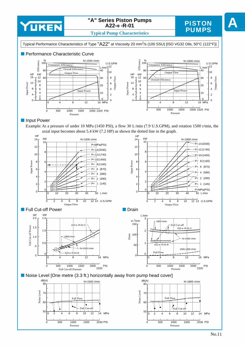
"A" Series Piston Pumps A22-∗-R-01
Typical Performance Characteristics of Type "A22" 2 at Viscosity 20 mm /s (100 SSU) [ISO VG32 Oils, 50°C (122°F)]
Performance Characteristic Curve
Input PowerAt a pressure of under 10 MPa (1450 PSI), a flow 30 L/min (7.9 U.S.GPM), and rotation 1500 r/min, the axial input becomes about 5.4 kW (7.2 HP) as shown the dotted line in the graph.
Example:
Full Cut-off Power Drain
Noise Level [One metre (3.3 ft.) horizontally away from pump head cover]
No.11

PISTON PUMPSTypical Pump Characteristics
3
Dra
in
2
1
0
L /min
150
120
30
0
3 in. /min
N=1500 r/min
Volumetric Efficiency
Output Flow
Overall Efficiency
Input Power
Effic
ienc
y
60
80
100%
Inpu
t Pow
er
0
10
20
30
0
10
20
40HP kW
30
0 4 8 12 16 2021
MPa
0 500 1000 1500 2000 2500 3050 PSIPressure
0
20
L /min
40
60
Out
put F
low
U.S.GPM
0
4
8
12
16
N=1500 r/minVolumetric Efficiency
Overall Efficiency
Output Flow
Input Power
N=1800 r/min
Effic
ienc
y
60
80
100%
Inpu
t Pow
er
0
10
20
30
0
10
20
40HP kW
30
0 4 8 12 16 2021
MPa
0 500 1000 1500 2000 2500 3050 PSIPressure
Out
put F
low
0
4
8
12
16
20U.S.GPM
0
20
L /min
40
60
80
N=1500 r/minP=MPa(PSI)P=P=P=P=P=P=P=P=P=P=P=
201816141210
86421
(2900)(2610)(2320)(2030)(1740)(1450)(1160)
(870)(580)(290)(150)
35 kWHP
25
20
15
10
5
0
25
15
5
0
Inpu
t Pow
er
10
20
30
0 L /min10 30 40 50 60 7020
U.S.GPM0 182 6 8 10 12 14 16Output Flow
4
N=1800 r/minP=MPa(PSI)P=P=P=P=P=P=P=P=P=P=P=
201816141210
86421
(2900)(2610)(2320)(2030)(1740)(1450)(1160)
(870)(580)(290)(150)
35 kWHP
25
20
15
10
5
0
25
15
5
0
Inpu
t Pow
er
10
20
30
0 L /min10 30 40 50 60 7020
U.S.GPM0 182 6 8 10 12 14 16Output Flow
4
A37-∗-R-01-H4
kWHP3
Full
Cut
-off
Pow
er
2
1
0
3
2
1
0
A37-∗-R-01-C
A37-∗-R-01-B
N=1500 r/min
N=1800 r/min
0 4 8 12 16 2021
Full Cut-off Pressure0 3050
MPa
PSI500 1000 1500 2000 2500
0 4 8 12 16 2021
0 3050
MPa
PSI500 1000 1500 2000 2500
A37-∗-R-01-C
A37-∗-R-01-B
Full Flow
Full Cut-offN=1800 r/min
N=1500 r/minA37-∗-R-01-H
1500,1800 r/min
60
90
180
021
0
MPa
PSI
4 8 12 16 20
3050Pressure
500 1000 1500 2000 2500
Full Flow
Full Cut-offNoi
se L
evel
80
70
60
50
40
dB(A)
Full Flow
Full Cut-off
N=1800 r/min
Pressure
Noi
se L
evel
80
70
60
50
40
dB(A)
021
0
MPa
PSI
4 8 12 16 20
3050Pressure
500 1000 1500 2000 2500
No.12
"A" Series Piston Pumps A37-∗-R-01
Typical Performance Characteristics of Type "A37" 2 at Viscosity 20 mm /s (100 SSU) [ISO VG32 Oils, 50°C (122°F)]
Performance Characteristic Curve
Input PowerAt a pressure of under 16 MPa (2320 PSI), a flow 45 L/min (11.9 U.S.GPM), and rotation 1500 r/min, the axial input becomes about 12.6 kW (16.9 HP) as shown the dotted line in the graph.
Example:
Full Cut-off Power Drain
Noise Level [One metre (3.3 ft.) horizontally away from pump head cover]

PISTON PUMPS
ATypical Pump Characteristics
N=1500 r/min
Full Cut-off Pressure
Volumetric Efficiency
Output Flow
Overall Efficiency
Input Power
Effic
ienc
y
%
Inpu
t Pow
er
0
HPkW
60
80
100
0
20
40
20
40
60
0 4 8 12 16 2021
MPa
0 500 1000 1500 2000 2500 3050 PSIPressure
020
L /min
4060
Out
put F
low
U.S.GPM
0
80100
510152025
N=1800 r/minVolumetric Efficiency
Overall Efficiency
Output Flow
Input Power
Effic
ienc
y
%
Inpu
t Pow
er
0
HPkW
60
80
100
0
20
40
20
40
60
020
L /min
4060
Out
put F
low
U.S.GPM
0
80100
510152025
12030
0 4 8 12 16 2021
MPa
0 3050 PSIPressure
500 1000 1500 2000 2500
Inpu
t Pow
er
HP kW
05
10
15
20
25
30
35
40
0
10
20
30
40
50N=1500 r/min
0 20 40 60 L /min80 120
U.S.GPMOutput Flow
100
0 305 10 15 20 25
P=MPa(PSI)
P=P=P=P=P=P=P=P=P=P=
201816141210
8642
(2900)(2610)(2320)(2030)(1740)(1450)(1160)
(870)(580)(290)
N=1800 r/min
P=MPa(PSI)
P=P=P=P=P=P=P=P=P=P=
201816141210
8642
(2900)(2610)(2320)(2030)(1740)(1450)(1160)
(870)(580)(290)
Inpu
t Pow
er
HP kW
05
10
15
20
25
30
35
40
0
50
10
20
30
40
0 20 40 60 L /min80 120
U.S.GPMOutput Flow
100
0 305 10 15 20 25
N=1500 r/min
N=1800 r/min
5kWHP 4
Full
Cut
-off
Pow
er 3
2
1
0
4
3
2
1
00 4 8 12 MPa16
0 500 1000 1500 2000 PSI
2021
2500 3050
4
Dra
in 2
1
0
L /min
200
100
50
0
3 in. /min
150
3
0 4 8 12 MPa16
0 500 1000 1500 2000 PSI
2021
2500 3050
Full Flow
Full Cut-off
1500,1800 r/min
N=1800 r/min
N=1500 r/min
A56-∗-R-01-C
A56-∗-R-01-H
A56-∗-R-01-B
Pressure
0 4 8 12 MPa16
0 500 1000 1500 2000 PSI
2021
2500 3050
Pressure
Full Flow
Full Cut-off
N=1500 r/min
Noi
se L
evel
80
70
60
50
dB(A) N=1800 r/min
Full Flow
Full Cut-off
0 4 8 12 MPa16
0 500 1000 1500 2000 PSI
2021
2500 3050
Pressure
Noi
se L
evel
80
70
60
50
dB(A)
"A" Series Piston Pumps A56-∗-R-01
Typical Performance Characteristics of Type "A56" 2 at Viscosity 20 mm /s (100 SSU) [ISO VG32 Oils, 50°C (122°F)]
Performance Characteristic Curve
Input PowerAt a pressure of under 16 MPa (2320 PSI), a flow 70 L/min (18.5 U.S.GPM), and rotation 1500 r/min, the axial input becomes about 20.8 kW (27.9 HP) as shown the dotted line in the graph.
Example:
Full Cut-off Power Drain
Noise Level [One metre (3.3 ft.) horizontally away from pump head cover]
No.13

PISTON PUMPSTypical Pump Characteristics
Dra
in
N=1500 r/min
N=1500 r/min
60
80
100%
Inpu
t Pow
er
0
20
40
60
0
20
40
80HP kW
60
Volumetric Efficiency
Overall Efficiency
Output Flow
Input Power
L /min120
100
80
30U.S.GPM
Out
put F
low
25
20
0 MPa5 10 15 20 25
0 1000 2000 3000 3500 PSIPressure 3630
0 MPa5 10 15 20 25
0 1000 2000 3000 3500 PSIPressure 3630
L /min
120
100
140
30
U.S.GPM
Out
put F
low
25
35
Inpu
t Pow
er
0
20
40
60
0
20
40
80HP kW
60
60
80
100% N=1800 r/min
Volumetric Efficiency
Overall Efficiency
Output Flow
Input Power
kWHP60
50
40
30
0
Inpu
t Pow
er
20
10
80
0
60
40
20
0 L /min20 60 80 100 120 14040
U.S.GPM0 35Output Flow
20 3010
N=1500 r/min kWHP60
50
40
30
0
Inpu
t Pow
er
20
10
80
0
60
40
20
N=1800 r/min
0 L /min20 60 80 100 120 14040
U.S.GPM0 35Output Flow
20 3010
1800 r/min
1500 r/min
Full
Cut
-off
Pow
er
0
HP kW
2
4
6
810
01
2
3
4
5
6
7
0 5 10 15 20 25
03630
MPa
PSI1000 2000 3500Full Cut-off Pressure
1500,1800 r/min
Full Cut-off
Full Flow1500,1800 r/min
0
100
200
300
01
2
3
4
5
6
7L /min3 in. /min
400
0 5 10 15 20 25
03630
MPa
PSI1000 2000 3500Pressure
30003000
Full Flow
Full Cut-offNoi
se L
evel
80
70
60
50
dB(A)
0 5 10 15 20 25
03630
MPa
PSI1000 2000 35003000Pressure
Full Flow
Full Cut-off
N=1800 r/min
Noi
se L
evel
80
70
60
50
dB(A)
0 5 10 15 20 25
03630
MPa
PSI1000 2000 35003000Pressure
Effic
ienc
y
Effic
ienc
y
P=MPa(PSI)
P=P=P=P=P=P=P=P=P=P=
201816141210
8642
(2900)(2610)(2320)(2030)(1740)(1450)(1160)(870)(580)(290)
P= 22(3190)P= 24(3480)
P=MPa(PSI)
P=P=P=P=P=P=P=P=P=P=
201816141210
8642
(2900)(2610)(2320)(2030)(1740)(1450)(1160)
(870)(580)(290)
P= 22(3190)P= 24(3480)
No.14
"A" Series Piston Pumps A70-∗R01
Typical Performance Characteristics of Type "A70" 2 at Viscosity 32 mm /s (150 SSU) [ISO VG32 Oils, 40°C (104°F)]
Performance Characteristics Curve
Input PowerAt a pressure of under 20 MPa (2900 PSI), a flow 70 L/min (18.5 U.S.GPM), and rotation 1500 r/min, the axial input becomes about 26 kW (35 HP) as shown the dotted line in the graph.
Example:
Full Cut-off Power Drain
Noise Level [One metre (3.3 ft.) horizontally away from pump head cover]

PISTON PUMPS
ATypical Pump Characteristics
N=1500 r/min
Effic
ienc
y
N=1800 r/min
N=1500 r/min
%
60
80
100
Volumetric Efficiency
Overall Efficiency
Output FlowL /min
Out
put F
low
U.S.GPM
3436
14038
130
120Input Power
Inpu
t Pow
er
HP kW
020
40
60
0
40
80
0 MPa5 10 15 20 25
0 3500 PSIPressure 3630
1000 2000 3000
L /min
Out
put F
low
U.S.GPM
404216044
150
140
170
N=1800 r/min
Volumetric Efficiency
Overall Efficiency
0 MPa5 10 15 20 25
0 3500 PSIPressure 3630
1000 2000 3000
Effic
ienc
y
%
60
80
100
Inpu
t Pow
er
HP kW
020
40
60
0
40
80
80100
Output Flow
Input Power
0 L /min20 60 80 100 120 14040
U.S.GPM0 35Output Flow
20 30105 15 25
N=1500 r/min
Inpu
t Pow
er
HP
kW
0
10
20
30
70
0
80
20
40
60
60
50
40
0 L /min20 60 80 100 120 14040
U.S.GPM0 35Output Flow
20 30105 15 25
160
40 45
Inpu
t Pow
er
HPkW
0
10
20
30
70
0
80
20
40
60
60
50
40
100
Full
Cut
-off
Pow
er
0
HP kW
2
4
6
89
01
2
3
4
5
6
7
1800 r/min
1500 r/min
0 5 10 15 20 25 MPa
Full Cut-off Pressure0 3500 PSI
36301000 2000 3000
1800 r/min
1500 r/min 1800 r/min
1500 r/min
Dra
in
0
100
200
300
0
2
4
6
L /min3 in. /min
400
8500
0 5 10 15 20 25 MPa
Pressure0 3500 PSI
36301000 2000 3000
Full Flow
Full Cut-offNoi
se L
evel
80
70
60
50
dB(A)
0 5 10 15 20 25 MPa
Pressure0 3500 PSI
36301000 2000 3000
0 5 10 15 20 25 MPa
Pressure0 3500 PSI
36301000 2000 3000
N=1800 r/min
Noi
se L
evel
80
70
60
50
dB(A)
Full Flow
Full Cut-off
Full Cut-off
Full Flow
P=MPa(PSI)
P=P=P=P=P=P=P=P=P=P=
201816141210
8642
(2900)(2610)(2320)(2030)(1740)(1450)(1160)(870)(580)(290)
P= 22(3190)P= 24(3480)P= 25(3630)
P=MPa(PSI)
P=P=P=P=P=P=P=P=P=P=
201816141210
8642
(2900)(2610)(2320)(2030)(1740)(1450)(1160)
(870)(580)(290)
P= 22(3190)P= 24(3480)P= 25(3630)
"A" Series Piston Pumps A90-∗R01
Typical Performance Characteristics of Type "A90" 2 at Viscosity 32 mm /s (150 SSU) [ISO VG32 Oils, 40°C (104°F)]
Performance Characteristics Curve
Input PowerAt a pressure of under 18 MPa (2610 PSI), a flow 110 L/min (29.1 U.S.GPM), and rotation 1500 r/min, the axial input becomes about 34 kW (46 HP) as shown the dotted line in the graph.
Example:
Full Cut-off Power Drain
Noise Level [One metre (3.3 ft.) horizontally away from pump head cover]
No.15

PISTON PUMPSTypical Pump Characteristics
N=1500 r/min
0 MPa5 10 15 20 25
0 3500 PSIPressure 3630
1000 2000 3000
Volumetric EfficiencyL /min
210
200
220
56
U.S.GPM
Out
put F
low
54
58
Inpu
t Pow
er
040
80
120
04080
160HP kW
120
60
80
100%
Output Flow
Overall Efficiency
Input Power
N=1800 r/min
Inpu
t Pow
er
040
80
120
04080
160HP kW
120
60
80
100%
L /min
260
250
270
68
U.S.GPM
Out
put F
low
66
70
240
0 MPa5 10 15 20 25
0 3500 PSIPressure 3630
1000 2000 3000
Volumetric Efficiency
Overall Efficiency
Output Flow
Input Power
N=1500 r/minkW
HP140
Inpu
t Pow
er
120
100
80
60
40
200
160140120100
80604020
00 L /min
U.S.GPMOutput Flow
40 80 120 160 200 240
0 10 20 30 40 50 60
P=MPa(PSI)
P=P=P=P=P=P=P=P=P=P=
2018161412108642
(2900)(2610)(2320)(2030)(1740)(1450)(1160)(870)(580)(290)
P= 22(3190)P= 24(3480)P= 26(3770)P= 28(4060)
P= 1 (145)
P=MPa(PSI)
P=P=P=P=P=P=P=P=P=P=
2018161412108642
(2900)(2610)(2320)(2030)(1740)(1450)(1160)(870)(580)(290)
P= 22(3190)P= 24(3480)P= 26(3770)P= 28(4060)
P= 1 (145)
N=1800 r/min
0 L /min
U.S.GPMOutput Flow
40 80 120 160 200 240
0 10 20 30 40 50 60
280
70
kWHP 140
Inpu
t Pow
er
120
100
80
60
40
200
160140120100
80604020
0
180
1800 r/min
1500 r/min
0 MPa5 10 15 20 25
0 3500 PSIFull Cut-off Pressure 3630
1000 2000 3000
Full
Cut
-off
Pow
er
0
HP
kW
5
10
15
0
2.5
5.0
7.5
10.0
12.5
1800 r/min
1500 r/min
Full Cut-off
Full Flow
0 MPa5 10 15 20 25
0 3500 PSIPressure 3630
1000 2000 3000
Dra
in
0
200
0
2.5
7.5
10.0L /min3 in. /min
600
400
5
Noi
se L
evel
90
70
60
dB(A)
80
N=1500 r/min
0 MPa5 10 15 20 25
0 3500 PSIPressure 3630
1000 2000 3000
Full Flow
Full Cut-off
0 MPa5 10 15 20 25
0 3500 PSIPressure 3630
1000 2000 3000
N=1800 r/min
Noi
se L
evel
90
70
60
dB(A)
80Full Flow
Full Cut-off
Effic
ienc
y
Effic
ienc
y
No.16
"A" Series Piston Pumps A145-∗R01
Typical Performance Characteristics of Type "A145" 2 at Viscosity 32 mm /s (150 SSU) [ISO VG32 Oils, 40°C (104°F)]
Performance Characteristics Curve
Input PowerAt a pressure of under 20 MPa (2900 PSI), a flow 180 L/min (47.6 U.S.GPM), and rotation 1500 r/min, the axial input becomes about 64 kW (86 HP) as shown the dotted line in the graph.
Example:
Full Cut-off Power Drain
Noise Level [One metre (3.3 ft.) horizontally away from pump head cover]

PISTON PUMPS
1.2.
3.
2 3 2 3
3
1
AInstallation Drawing
Model Numbers"C" Thd. "D" Thd.
Rc 3/8 3/8 BSP.F 3/8 NPT
A10-FR01∗-12 A10-FR01∗-1280 A10-FR01∗-1290
Thread Size
Rc 1/2 1/2 BSP.F 1/2 NPT
Model NumbersTughtening Torque Nm(IN. lbs.)
Suction Port & Discharge Port Drain Port
A10-FR01B-12/1290 A10-FR01C/H-12/1290 A10-FR01B-1280 A10-FR01C/H-1280
65-75 (575-664) 65-75 (575-664)
98-108 (867-956) 98-108 (867-956)
40-50 (354-443) 40-50 (354-443) 39-43 (345-381) 39-43 (345-381)
17(.67)
50(1.97)
56.5(2.22)
95(3.74)
27.5(1.08)
(3.74)72.5 72.5
(2.854)180
(7.09)
80(3
.15)
15 (.59)
145.
5(5
.73)
3(.1
2)
12(.47) Dia. Through 24(.94) Dia. Spotface 4 Places
Mtg. Bracket
Hex. Bolt (2 Pcs.)
M10×25 Lg.
Plain Washer (2 Pcs.) (2.854)
95
Pressure Adj. Screw 13(.51) Hex.
INC.
Flow Adj. Screw 13(.51) Hex.
DEC.
Suction Port "C" Thd.
Fully Extended103(4.06)
34(1.34) Dia. Spotface 2 Places
Discharge Port "C" Thd.
85(3
.35)
25(.98)
25(.98)
64.5(2.54)
64.5(2.54)
167
(6.5
7) 103
(4.0
6)41
(1.6
1)
Fully Extended186(7.32)
44.5(1.75)
6.5(.26)90.5(3.56)
(2.07)52.5 25(.98)
10.5(.41)
131(5.16)156
(6.14)159.5(6.28)
65(2
.56)
19.0
5(.7
500)
19.0
2(.7
488)
Dia
.
21.2
4(.8
36)
21.0
8(.8
30)
82.5
5(3.
250)
82.5
0(3.
248)
Dia
. 31(1
.22)
12 (.47)
106(4.17)130
(5.12)93(3.66) Dia.
4.79(.1886) 4.76(.1874)
25(.98)
25(.98)
64.5(2.54)
64.5(2.54)
131(5.16)156
(6.14)
Key Width
Drain Port "D" Thd.
Filling Port [8(.31) Hex. Soc. Plug Furnished]
DIMENSIONS IN MILLIMETRES (INCHES)
14 (.55)
No.17
"A" Series Piston Pumps A10-FR01
Install the pump so that the "Filling Port" is at the top.Use either port of two suction and discharge ports at your option. Keep the remaining ports plugged.As the tightening torques of suction, discharge and drain port fittings, conform to the below.
Mounting Bracket Kit: LP-1A-10
Flange Mtg.: A10-FR01B-12/1280/1290
Flange Mtg.: A10-FR01C-12/1280/1290A10-FR01H-12/1280/1290
For other dimensions, refer to above drawing.

PISTON PUMPS
Axial Port Type
Side Port Type
Installation Drawing
Model Numbers "C" Thd. "D" Thd.Rc 3/8
3/8 BSP.F 3/8 NPT
M 10
3/8-16 UNC
A16/A22-F-R-01-∗-K-32 A16/A22-F-R-01-∗-K-3280
74(2.91)
74(2.91)
Surface of Suction Port Surface of Discharge Port
22.2(.874)
150.5(5.93)
188(7.40)
Fully Extended219(8.62)
44.5(1.75)
109(
4.29
)78
(3.0
7)
47.6
(1.8
74)
Discharge Port 19 (.75) Dia.Rear Side Suction Port 19 (.75) Dia."D" Thd. 17 (.67) Deep
4 Places (Both Sides)
95(3.74)
27.5(1.08)
50(1.969)
56.5(2.22)
180(7.09)
72.5(2.854)
72.5(2.854)
95(3.74)
80(3
.15)
15 (.59)
14 (.55)
12(.47) Dia. Through 24(.94) Dia. Spotface 4 Places
4.79(.1886) 4.76(.1874)
R12 (R .47)
18 (.71)
12 (.47)
95(3.74) Dia.106
(4.17)130
(5.12)188
(7.40)
96(3
.78)Dia
.
19.0
5(.7
500)
19.0
2(.7
488)
Dia
.
21.2
4(.8
36)
21.0
8(.8
30)
12(.47)
172(6.77)
62(2
.44)10
9(4
.29)
187
(7.3
6)
Fully Extended219(8.62)
Discharge Port 19 (.75) Dia.
44.5(1.75)
59(2.32)
6.5(.26)
26.5(1.04)
25(.98)
Filling Port [22(.87) Hex. Head Plug Furnished]
Drain Port "C" Thd.
Lock Nut 17(.67) Hex.
Pressure Adj. Screw 17(.67) Hex.
Flow Adj. Screw 17(.67) Hex.
DEC.
16(.63)
16(.63)
47.6
(1.8
74)
22.2(.874)
65(2.56)
Suction Port 19(.75) Dia.
"D" Thd. 17(.67) Deep 8 Places
INC.
82.5
5(3.
250)
82.5
0(3.
248)
3(.1
2)
No.18
"A" Series Piston Pumps A16 / A22-F-R-01
Flange Mtg.: A16-F-R-01-∗-S-K-32/3280/3290A22-F-R-01-∗-S-K-32/3280/3290
Foot Mtg.: A16-L-R-01-∗-K-32/3280/3290A22-L-R-01-∗-K-32/3280/3290
Flange Mtg.: A16-F-R-01-∗-K-32/3280/3290A22-F-R-01-∗-K-32/3280/3290
For other dimensions, refer to "Axial Port Type".
For other dimensions, refer to "Flange Mtg.".
Install the pump so that the "Filling Port" is at the top.
DIMENSIONS IN MILLIMETRES (INCHES)

PISTON PUMPS
Side Port Type
Axial Port Type
AInstallation Drawing
Model Numbers "C" Thd.Rc 1/2
1/2 BSP.F A37-F-R-01-∗-K-32 A37-F-R-01-∗-K-3280
Model Numbers "C" Thd. "D" Thd.
Rc 1/2 1/2 BSP.F 1/2 NPT
M 10
7/16-14 UNC
A37-F-R-01-S-∗-K-32 A37-F-R-01-S-∗-K-3280 A37-F-R-01-S-∗-K-3290
E mm (IN.)
19 (.75)
20 (.79)
39(1.54)
120(4.72)
60(2.362)
230(9.06)
95(3.740)
102
(4.0
2)
15 (.59)
14 (.55)
14(.55) Dia. Through 28(1.10) Dia. Spotface 4 Places
3(.1
2)
95(3.740)
74(2.91)
115(4.53)
Discharge Port 32 (1.26) Dia.
Flow Adj. Screw
17(.67) Hex.
DEC.
13(.51)
19(.75)
58.7
(2.3
11)
30.2(1.189)
72(2.83)
Suction Port 32(1.26) Dia.
M10 Thd. 19(.75) Deep 8 Places
Pressure Adj. Screw 17(.67) Hex.
INC.
202
(7.9
5)11
2(4
.41)
68(2
.68)
Fully Extended247(9.72)
59(2.32)Lock Nut 17(.67) Hex.
30(1.18)
77(3.03)
9.5(.37)
32(1.26)
195(7.68)
12(.47)
22.2
3(.8
752)
22.2
0(.8
740)
Dia
.
25.0
1(.9
85)
24.8
5(.9
78)
101.
60(4
.000
) Dia
.10
1.55
(3.9
98)
6.38(.2512) 6.35(.2500)
R14 (R .55)
25 (.98)
14 (.55)
120(4.72) Dia.146
(5.75)174
(6.85)202
(7.95)
105
(4.1
3)
86(3.39)Surface of
Suction PortSurface of
Discharge Port
86(3.39)
59(2.32)
Fully Extended247(9.72)
Discharge Port 32 (1.26) Dia.
Rear Side Suction Port 32 (1.26) Dia.
"D" Thd. "E" Deep 4 Places (Both Sides)
30.2(1.189)
112(
4.41
)
202(
7.95
)
58.7
(2.3
11)
178.5(7.03)
202(7.95)
Filling Port [22(.87) Hex. Head Plug Furnished]
Drain Port "C" Thd.
No.19
For other dimensions, refer to "Axial Port Type".Foot Mtg. Type; Mounting bracket is common to that of "Axial Port Type".
For other dimensions, refer to "Flange Mtg.".
Install the pump so that the "Filling Port" is at the top.Note: "Axial Port Type" is not available for N.American design Standard.
DIMENSIONS IN MILLIMETRES (INCHES)
Foot Mtg.: A37-L-R-01-∗-K-32/3280
Flange Mtg.: A37-F-R-01-∗-S-K-32/3280/3290
Flange Mtg.: A37-F-R-01-∗-K-32/3280
"A" Series Piston Pumps A37-F-R-01

PISTON PUMPS
Axial Port Type
Side Port Type
1.2.
1
2
Installation Drawing
Model Numbers "C" Thd.Rc 3/4
3/4 BSP.F A56-F-R-01-∗-K-32 A56-F-R-01-∗-K-3280
Model Numbers "C" Thd. "D" Thd.
Rc 3/4 3/4 BSP.F 3/4 NPT
M 10
7/16-14 UNC
A56-F-R-01-S-∗-K-32 A56-F-R-01-S-∗-K-3280 A56-F-R-01-S-∗-K-3290
E mm (IN.)
19 (.75)
20 (.79)
62(2.44)Fully Extended
Discharge Port 30 (1.18) Dia.Rear Side Suction Port 35 (1.38) Dia."D" Thd. "E" Deep
4 Places (Both Sides)
30.2(1.189)
138
(5.4
3)
236
(9.2
9)
58.7
(2.3
11)
191(7.52)
232(9.13)
100(3.94)Surface of
Suction PortSurface of
Discharge Port
259.5(10.22)
100(3.94)
42(1.65)
120(4.72)
60(2.362)
230(9.06)
95(3.740)
102
(4.0
2)
15 (.59)
14 (.55)
14(.55) Dia. Through 28(1.10) Dia. Spotface 4 Places
3(.1
2)
95(3.740)
115(4.53)
77(3.03)
7.97(.3138) 7.94(.3126)
R14 (R.55)
25 (.98)
14 (.55)
120(4.72) Dia. 146(5.75)174
(6.85)232
(9.13)
41(1.61)
49(1.93)
Surface of Drain Port
101.
60(4
.000
) Dia
.
Filling Port [22(.87) Hex. Head Plug Furnished]
Drain Port "C" Thd. (Both Sides)
101.
55(3
.998
)
35.3
2(1.
391)
35.1
4(1.
383)
31.7
5(1.
250)
31.7
0(1.
248)
Dia
.
207(8.15)
12(.47)
40(1.57)
9.5(.37)
50.5(1.99)
43.5(1.71)
62(2.44)Fully Extended
259.5(10.22)
77(3
.03)
Lock Nut 17(.67) Hex.
90(3
.54)13
8(5
.43)
236
(9.2
9)13
(.51)19
(.75)
30.2(.189)
(2.99)26
58.7
(2.3
11)
Discharge Port 32 (1.26) Dia.
Flow Adj. Screw
17(.67) Hex.
DEC.
Suction Port 35(1.38) Dia.
"MIO" Thd. 19(.75) Deep 8 Places
Pressure Adj. Screw 17(.67) Hex.
INC.
No.20
"A" Series Piston Pumps A56-F-R-01
Flange Mtg.: A56-F-R-01-∗-S-K-32/3280/3290
Foot Mtg.: A56-L-R-01-∗-K-32/3280
Flange Mtg.: A56-F-R-01-∗-K-32/3280
Install the pump so that the "Filling Port" is at the top.Use either port of the two drain ports at your option. Keep the remaining port plugged. Note that on the European design standard (3280 Design), only the left side, as viewed from the shaft end, of the drain port is machined.
Note: "Axial Port Type" is not available for N.American design Standard.
For other dimensions, refer to "Flange Mtg.".
For other dimensions, refer to "Axial Port Type".Foot Mtg. Type; Mounting bracket is common to that of "Axial Port Type".
DIMENSIONS IN MILLIMETRES (INCHES)

PISTON PUMPS
1.2.
3.
1
2
A
3
Installation Drawing
Model Numbers "C" Thd. "D" Thd.
Rc 3/4 3/4 BSP.F 3/4 NPT
M 12
1/2-13 UNC
A70-FR01∗S-60 A70-FR01∗S-6080 A70-FR01∗S-6090
19 (.75)
21 (.83)
"E" Thd.
M 10
3/8-16 UNC
F mm (IN.)
125(4.921)
195(7.68)
37(1.46)
77(3.03)
127
(5.0
0)D
ia.
130
(5.1
2)
(6.73)130
3(.1
2)
(5.118)
171
130(5.118)
320(12.60)
24(.9
4)
25(.9
8)
22(.87) Dia. Through 43(1.69) Dia. Spotface 4 Places
42.5(1.67)
Y X
Pressure Adj. Screw 17(.67) Hex.
Flow Adj. Screw 17(.67) Hex.
DEC.INC.
Suction Port 38(1.50) Dia.
"D" Thd. "F" Deep 4 Places
Case Drain Port 5(.20) Hex. Soc.
Filling Port [22(.87) Hex. Head Plug Furnished]
Eye Bolt M10
69.9
(2.7
52)
246.5(9.70)
35.7(1.406)
Drain Port "C" Thd. (Both Sides)
Discharge Port 26(1.02) Dia.
"E" Thd. 17(.67) Deep
4 Places
16(.63)
18(.71)
26.2(1.301)
246.5(9.70)
Fully Extended310.5(12.22)
62(2.44)
65(2.56)
19.5(.77)
9.5(.37)
40(1.57)
31.7
5(1.
250)
31.7
0(1.
248)
Dia
.
35.3
2(1.
391)
35.1
4(1.
383)
127.
00(5
.000
) Dia
.12
6.95
(4.9
98)
90(3
.54)
18(.7
1)
14(.5
5)
114.4(4.50)134
(5.28)181
(7.13)211
(8.31)
114.
4(4
.50)
180
(7.0
9)18
2(7
.17)
118
(4.6
5)
14(.5
5)
7.94(.3126)7.97(.3138)73
(2.87) (2.87)
95(3.74)
95(3.74)
Surface of Discharge Port
Surface of Drain Port
Surface of Drain Port
Surface of Suction Port
35(1.38) Dia. Spotface
(From Rear) 2 Places
27(1.06) Dia. Spotface (From Rear)
4 Places
52.4
(2.0
63)
73
No.21
"A" Series Piston Pumps A70-FR01
Flange Mtg.: A70-FR01∗S-60/6080/6090
Foot Mtg.: A70-LR01∗S-60/6080/6090
View Arrow Y
View Arrow XInstall the pump so that the "Filling Port" is at the top.Use either port of the two drain ports at your option. Keep the remaining port plugged. Note that on the European design standard (6080 design), only the left side, as viewed from the shaft end, of the drain port is machined.Case drain port is available for use when draining hydraulic fluidfrom pump casing.
For other dimensions, refer to "Flange Mtg.".
DIMENSIONS IN MILLIMETRES (INCHES)

PISTON PUMPS
2
3
1
1.
2.
3.
Installation Drawing
Model Numbers "C" Thd. "D" Thd.
Rc 3/4 3/4 BSP.F 3/4 NPT
M 12
1/2-13 UNC
A90-FR01∗S-60 A90-FR01∗S-6080 A90-FR01∗S-6090
19 (.75)
21 (.83)
"E" Thd.
M 10
7/16-14 UNC
F mm (IN.)
Y
Fully Extended329(12.95)
119.5(4.70)
13(.51)
63(2.48)
30.2(1.189)
270(10.63)
22 (.87)23
(.91)
38.1
0(1.
500)
38.0
5(1.
498)
Dia
.
42.3
6(1.
668)
42.1
8(1.
661)
152.
40(6
.000
) Dia
.15
2.35
(5.9
98)
113
(4.4
5)
58.7
(2.3
11)
105(4.13)
105(4.13)
(2.68)68
(2.68)68
9.53(.3752)
161.
6(6
.362
) 190.
5(7
.50)
X
127
(5.0
0)
R22 (R.87)161.6
(6.362)
Surface of Discharge Port
Surface of Drain Port
Surface of Drain Port
Surface of Suction Port
21.5(.85) Dia. Through 39(1.54) Dia. Spotface
(From Rear) 4 Places
Case Drain Port 5(.2) Hex. Soc.
Discharge Port 32(1.26) Dia.
"E" Thd. "F" Deep 4 Places
Drain Port "C" Thd. (Both Sides)
Pressure Adj. Screw 17(.67) Hex.Flow Adj. Screw
17(.67) Hex.
DEC.INC. Suction Port
48(1.89) Dia.
"D" Thd. "F" Deep 4 Places
Filling Port [27(1.06) Hex. Head Plug Furnished]
Eye Bolt M10
77.8
(3.0
63)
270(10.63)
42.9(1.689)
125(4.921)
200(7.87)
70(2.76)
110(4.33)
140
(5.5
1)
(8.46)
3(.1
2)
215
157.5(6.201)
375(14.76)
24(.9
4)
25(.9
8)
22(.87) Dia. Through 43(1.69) Dia. Spotface 4 Places
157.5(6.201)
23(.91)
95(3.74)
9.56(.3764)
No.22
"A" Series Piston Pumps A90-FR01
Flange Mtg.: A90-FR01∗S-60/6080/6090
Foot Mtg.: A90-LR01∗S-60/6080/6090
Install the pump so that the "Filling Port" is at the top.
Use either port of the two drain ports at your option. Keep the remain-ing port plugged. Note that on the European design standard (6080 design), only the left side, as viewed from the shaft end, of the drain port is machined.Case drain port is available for use when draining hydraulic fluid from pump casing.
View Arrow Y
View Arrow X
DIMENSIONS IN MILLIMETRES (INCHES)
For other dimensions, refer to "Flange Mtg.".

PISTON PUMPS
1.
2.
3.
A
2
3
1
Installation Drawing
Model Numbers "C" Thd. "D" Thd.
Rc 3/4 3/4 BSP.F 3/4 NPT
M 12
1/2-13 UNC
A145-FR01∗S-60 A145-FR01∗S-6080 A145-FR01∗S-6090
19 (.75)
21 (.83)
"E" Thd.
M 10
7/16-14 UNC
F
19 (.75)
20 (.79)
HDimensions mm (IN.)
X
114.3(4.500)
185(7.28)
80(3.15)
119(4.69)
187.
3(7
.37)
(11.02)187.3
3(.1
2)
(7.374)
280
438(17.24)
29(1
.14)
30(1
.18)
187.3(7.374)
22(.87) Dia. Through 43(1.69) Dia. Spotface 4 Places
Pressure Adj. Screw 17(.67) Hex.
INC.Suction Port 48(1.89) Dia.
"D" Thd. "F" Deep 4 Places
Filling Port [27(1.06) Hex. Head Plug Furnished]
Eye Bolt M10
42.9(1.689)
299.5(11.79)
77.8
(3.0
63)
26(1.02)
30.2(1.189)
299.5(11.79)
24(.94)
Case Drain Port 5(.2) Hex. Soc.
Discharge Port 32(1.26) Dia.
"E" Thd. "H" Deep 4 Places
58.7
(2.3
11)
357.5(14.07)
112(4.41)
89(3.50)
23(.91)13
(.51)70
(2.76)
Drain Port "C" Thd. (Both Sides)
Flow Adj. Screw 17(.67) Hex.
110
(4.3
3)
44.4
5(1.
750)
44.4
0(1.
748)
Dia
.
49.3
9(1.
944)
49.2
1(1.
937)
152.
40(6
.000
) Dia
.15
2.35
(5.9
98)
R22 (R .87)
21.5(.85) Dia. Through 39(1.54) Dia. Spotface
(From Rear) 4 Places
228.6(9.00)273
(10.75)
228.
6(9
.00)
141
(5.5
5)19
8.5
(7.8
1)11.14 11.11.4386 .4374
72(2.83)
72(2.83)
112(4.41)
112(4.41)
143(5.63)
Surface of Discharge Port
Surface of Suction Port
Surface of Drain Port
Surface of Drain Port
INC.
No.23
"A" Series Piston Pumps A145-FR01
Flange Mtg.: A145-FR01∗S-60/6080/6090
Foot Mtg.: A145-LR01∗S-60/6080/6090
Install the pump so that the "Filling Port" is at the top.
Use either port of the two drain ports at your option. Keep the remaining port plugged. Note that on the European design standard (6080 design), only the left side, as viewed from the shaft end, of the drain port is machined.
Case drain port is available for use when draining hydraulic fluid from pump casing.
For other dimensions, refer to "Flange Mtg".
DIMENSIONS IN MILLIMETRES (INCHES)
View Arrow X

PISTON PUMPSSpare Parts List
Name of PartsItemQty.
Part Numbers
2 6 7 16 20 23 33 37 54 62 64
Oil Seal O-Ring Bearing O-Ring O-Ring O-Ring Bearing O-Ring O-Ring O-Ring O-Ring
Pres. Adj. RangeB C & H
TCN24408Y SO-NA-G50
6204 SO-NB-P14
SO-NB-G120 SO-NB-P6 HMK1215
SO-NB-P12 SO-NA-A018 SO-NB-P10 SO-NB-P9
1 1 1 1 1 2 1 6 1 1
1 1 1 1 1 2 1 5 1 1 1
Pump Model Numbers Seal Kit NumbersA10-FR01B-12/1280/1290 A10-FR01C-12/1280/1290 A10-FR01H-12/1280/1290
KS-A10-01B-12
KS-A10-01H-12
6160595857565554535251
63 62
37 41 64 39 23 37 36 35 38X
X
25 23 22 21 20 19 18 17 16 15 14 13 12 11 10
98
7
6
5
4321262728293031323334
24
No.24
"A" Series Piston Pumps A10-FR01
When making replacement of seals or bearings, please do it carefully after reading through the relevant instructions in the Operator's Manual.
CAUTION
List of Seals & Bearings
List of Seals Kits
When ordering seals, please specify the seal kit number from the table below.
A10-FR01∗-12/1280/1290
Section X-X

PISTON PUMPS
ASpare Parts List
Name of PartsItem Qty.Part Numbers
A16-∗-R-01 A22-∗-R-01 A37-∗-R-01 A56-∗-R-011 1 1 1 2 1 1 1 1 1 1
27 28 29 30 35 36 37 38 39 60 61
Bearing Bearing Oil Seal Gasket O-Ring O-Ring O-Ring O-Ring
Seal Washer O-Ring O-Ring
6305HMK 1715 Z30-1303-PK410300-8
TCN 254511 1303-PK211969-1
SO-NA-G25 SO-NB-P12
6307 HMK 2025V2 TCN 355511
1316-PK211970-9 SO-NB-G30
NUP 207E HMK 2530V2 TCN 355511
1307-PK211971-7 SO-NA-P36
SO-NB-P10ASO-NB-P9
SO-NA-A017 W8
SO-NB-P14SO-NA-G55 SO-NA-G75
Pump Model Numbers Seal Kit NumbersA16-∗-R-01-∗-K-∗-32∗ A22-∗-R-01-∗-K-∗-32∗ A37-∗-R-01-∗-K-∗-32∗ A56-∗-R-01-∗-K-∗-32∗
KS-A37-01-32 KS-A56-01-32
KS-A16-01-32
XX
25 40 35 9 2 44 3 25 11 52 60 31 4 22 1 3227
61
58
29
57
51
5
55
54
49
5321108172033193075028
426364116393412241815374338
47
46
23
45
1413
4356
No.25
"A" Series Piston Pumps A16 / A22 / A37 / A56-∗-R-01
When making replacement of seals or bearings, please do it carefully after reading through the relevant instructions in the Operator's Manual.
CAUTION
When ordering seals, please specify the seal kit number from the table below.
List of Seal Kits
List of Seal and Bearings
Section X-X
A16/A22/A37/A56-∗-R-01-∗-∗-K-32/3280/3290

PISTON PUMPSSpare Parts List
Name of PartsItem Qty.A70-∗R01∗S
5 22 38 39 40 42 43 44 67 68 70
Gasket Back Up Ring
Bearing Needle Bearing
Oil Seal O-Ring O-Ring O-Ring O-Ring
Seal Washer O-Ring
1314E-PK211972-5 1310E-PK412440-0
NUP 208EX50 HMK 3030V2 TCN 355511 SO-FA-G85 SO-NA-P18 SO-NB-P9
SO-NB-P14 W10
1 1 1 1 1 1 1 3 1 1 1
A90-∗R01∗SPart Numbers
1310E-PK211973-3 1310E-PK412440-0
NUP 210E HMK 3530BV2
TCN 456812 SO-FA-G95 SO-NA-P18 SO-NB-P9 SO-NB-P18
SO-NB-P5
Pump Model Numbers Seal Kit NumbersA70-∗R01∗S-60∗ A90-∗R01∗S-60∗
KS-A70-01-60 KS-A90-01-60
X
A
X
39 25 2 61 5 33 31 13 28 16 15 14 17 29 65 30
66
52
48
38
40
6
62
60
42
9
51
41367365632123755262755
25 26 27 28 29 30 31 32 33
23 58 44 11 7 8
24 19 43 21 20 18 10 54 50 44 68 69
59 22 44 70
Q
P
Z
Z
63
53
46
35
45
64
34
54
47
No.26
"A" Series Piston Pumps A70 / A90-∗R01
When making replacement of seals or bearings, please do it carefully after reading through the relevant instructions in the Operator's Manual.
CAUTION
When ordering the seals, please specify the seal kit number from the table left.
List of Seal Kits
A70/A90-∗R01∗S-60/6080/6090
Section X-X Section X-X (Only for "A70")
Detail "A" Section Z-Z
List of Seals and Bearings

PISTON PUMPS
ASpare Parts List
Name of PartsItem Qty.Part Numbers6
15 39 40 41 43 44 45 46 47 48 49 50 73
Gasket Back Up Ring
Bearing Needle Bearing
Oil Seal O-Ring O-Ring O-Ring O-Ring O-Ring O-Ring
Back Up Ring Back Up Ring
O-Ring
1 1 1 1 1 1 1 1 2 1 1 1 1 1
1312-PK211974-1 1310E-PK412440-0
NUP 2211ET2 8Q-NK38×55×30
TCN 507212 S-31.5 (NBR, Hs70)
SO-FA-G105 SO-NA-P18 SO-NB-P9
SO-NB-A017 SO-NB-A016
For SO-NB-A017 For SO-NB-A016
SO-NB-P18
X X
A
26 27 28 29 30 31 32 33 34
2 2634 11 6 1 32 38 10 13 12 16 71 31 72
28
57
39
64
4
68
41
54
44
9
61559733760316337814654662
40
30
7429
27
35
70
67
59
25
653652516958
53
63 4615
24 62 56 19 17 50 48 66 23
57
20
4947592218434521
No.27
"A" Series Piston Pumps A145-∗R01
A145-∗R01∗S-60/6080/6090
List of Seals and Bearings
When ordering seals, please specify the kit number "KS-A145-01-60".
Section X-X Detail "A"
When making replacement of seals or bearings, please do it carefully after reading through the relevant instructions in the Operator's Manual.
CAUTION


