dp27, dp27e, dp27g, dp27gy, dp27r and dp27y …a spirax-monnier pressure regulator with a compressed...
TRANSCRIPT
Local regulations may restrict the use of this product to below the conditions quoted.In the interests of development and improvement of the product, we reserve the right to change the specification without notice. © Copyright 2009
ISO 9001
Cert. No. LRQ 0963008
Page 1 of 9
TI-P470-01CH Issue 7
DP27, DP27E, DP27G, DP27GY, DP27R and DP27Y Pilot Operated
Pressure Reducing Valves with SG Iron Bodies
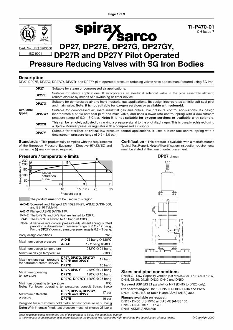
Description DP27, DP27E, DP27G, DP27GY, DP27R and DP27Y pilot operated pressure reducing valves have bodies manufactured using SG iron.
DP27 Suitable for steam or compressed air applications.
DP27E Suitable for steam applications. It incorporates an electrical solenoid valve in the pipe assembly allowing
remote closure by means of a switching or timer device.
DP27G Suitable for compressed air and inert industrial gas applications. Its design incorporates a nitrile soft seal pilot
and main valve. Note: it is not suitable for oxygen services or available with solenoid.
Suitable for compressed air, inert industrial gas and critical low pressure control applications. Its design DP27GY incorporates a nitrile soft seal pilot and main valve, and uses a lower rate control spring with a downstream pressure range of 0.2 - 3.0 bar. Note: it is not suitable for oxygen services or available with solenoid.
DP27R This can be remotely adjusted by varying a pressure signal to the pilot diaphragm. This is usually achieved using
a Spirax-Monnier pressure regulator with a compressed air supply.
DP27Y Suitable for steriliser or critical low pressure control applications. It uses a lower rate control spring with a
downstream pressure range of 0.2 - 3.0 bar.
The product must not be used in this region.
A-D-E Screwed and flanged EN 1092 PN25, ASME (ANSI) 300, and BS 10 Table H. A-B-C Flanged ASME (ANSI) 150. F-F-E The DP27G and DP27GY are limited to 120°C. G-G The DP27E is limited to 10 bar g @ 190°C. Note: A variable rate conical pressure adjustment spring is fitted providing a downstream pressure range of 0.2 - 17 bar g. For the DP27Y downstream pressure range is 0.2 - 3 bar g.
Body design conditions PN25
Maximum design pressure A-D-E 25 bar g @ 120°C
A-B-C 17.2 bar g @ 40°CMaximum design temperature 232°C @ 21 bar gMinimum design temperature -10°C
Maximum upstream pressure DP27, DP27G, DP27GY 17 bar g DP27R and DP27Y
for saturated steam service DP27E 10 bar g
DP27, DP27Y 232°C @ 21 bar gMaximum operating
DP27E 190°C @ 10 bar gtemperature DP27G, DP27GY 120°C @ 25 bar g
Minimum operating temperature 0°CNote: For lower operating temperatures consult Spirax Sarco DP27, DP27G, DP27GY 17 bar Maximum differential DP27R and DP27Ypressure DP27E 10 bar Designed for a maximum cold hydraulic test pressure of 38 bar gNote: With internals fitted, test pressure must not exceed 25 bar g
��
� �� �� �� ��
��
���
���
������
����Pressure bar g
Tem
per
atur
e °C
A
E
Steamsaturationcurve
C
FF
BD
G
G
Pressure / temperature limits DP27 shown
Standards - This product fully complies with the requirements of the European Pressure Equipment Directive 97 / 23 / EC and carries the mark when so required.
Sizes and pipe connectionsDN15LC - Low Capacity version (not available for DP27G or DP27GY) DN15, DN20, DN25, DN32, DN40 and DN50
Screwed BSP (BS 21 parallel) or NPT (DN15 to DN25 only).
Standard flanges: DN15 - DN50 EN 1092 PN16 and PN25 DN25 - DN50 BS 10 Table H and ASME (ANSI) 300
Flanges available on request:DN15 - DN50 JIS 10/16 and ASME (ANSI) 150 DN15 - DN20 BS 10 Table F DN15 ASME (ANSI) 300
Available types
Certification - This product is available with a manufacturer's Typical Test Report. Note: All certification / inspection requirements must be stated at the time of order placement.

DP27, DP27E, DP27G, DP27GY, DP27R and DP27Y Pilot Operated Pressure Reducing Valves with SG Iron Bodies TI-P470-01 CH Issue 7
Page 2 of 9
Materials - DP27 and DP27Y No. Part Material
1 Adjustment screw Steel BS 3692 Gr. 8.8
2 Adjustment lock-nut Steel BS 3692 Gr. 8
3 Spring housing SG iron DIN1693 GGG 40.3
4 Top spring plate Stainless ASTM A351/A351M steel CF8M
5 Pressure Stainless BS EN 10270-3:2001 adjustment spring steel 302 S 26
6 Bottom spring plate Brass BS 2872 CZ 122
7 Spring Securing nuts Steel BS 3692 Gr. 8
housing Securing studs Steel BS 4439 Gr. 8.8 DN15 to DN32 M10 x 95 mm DN40 and DN50 M12 x 95 mm
8 Pilot diaphragms Phosphor bronze BS 2870 PB102 1980
9 Pilot valve chamber SG iron DIN 1693 GGG 40.3
10 Pilot valve plunger Stainless steel BS 970 321 S 31
11 Pilot valve seat Stainless with integral seal steel + PTFE BS 970 431 S 29
12 Pilot valve ball Stainless steel AISI 420
13 Pilot valve spring Stainless steel BS 2057 302 S 26
14 Pilot valve clip Stainless BS EN 10088-2 1995 steel 1.4310
15 Pilot filter cap gasket Stainless steel BS 1449 316 S 11
16 Pilot filter cap Stainless steel BS 970 431 S 29
17 Pilot filter element Brass
18 Internal strainer Stainless steel ASTM A240 TP 304
19 Body gasket Stainless steel reinforced exfoliated graphite
20 Main valve return Stainless BS 2056 302 S 26 spring steel
21 Main valve Stainless steel BS 970 431 S 29
22 Main valve seat Stainless steel BS 970 431 S 29
23 Balance pipe assembly Copper BS 2871 C 106 ½H
24 Main valve body SG iron DIN 1693 GGG 40.3
Main Securing nuts Steel BS 3692 Gr. 825
body Securing studs Steel BS 4439 Gr. 8.8 DN15 to DN32 M10 x 25 mm DN40 and DN50 M12 x 30 mm
26 Main diaphragm SG iron chamber - upper DIN 1693 GGG 40.3
27 Main diaphragm SG iron chamber - lower DIN 1693 GGG 40.3
Main Securing nuts Steel BS 3692 Gr. 828
diaphragm Securing bolts Steel BS 3692 Gr. 8.8 DN15 to DN32 M12 x 50 mm DN40 and DN50 M12 x 55 mm
29 Main diaphragms Phosphor bronze BS 2870 PB 102 1980
30 Main diaphragm plate Brass BS 2872 CZ 122
31 Pushrod Stainless steel BS 970 431 S 29
32 Lock-nut Steel BS 3692 Gr. 8
33 Control pipe assembly Brass and copper
34 Plug " BSP Steel Note: This item is hidden from view
Note: Items 10, 12, 13 and 14 are shown on the exploded view, as they are hidden by the pilot filter on the main illustration.
1
2
5
4
76
8
33
11
151617
1820
24
31
32
30
9
23
19
2122
2528
26
27
*
*
*
3
19
29
*
Exploded view of item 11
*14
*13
*12
11
*10
*
For items 10, 12, 13 and 14 see the exploded view above
DP27 and DP27Y
Page 3 of 9
DP27, DP27E, DP27G, DP27GY, DP27R and DP27Y Pilot Operated Pressure Reducing Valves with SG Iron Bodies TI-P470-01 CH Issue 7
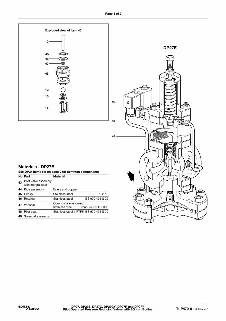
Materials - DP27ESee DP27 items list on page 2 for common components
No. Part Material
43 Pilot valve assembly with integral seal
44 Pipe assembly Brass and copper
45 Circlip Stainless steel 1.4116
46 Retainer Stainless steel BS 970 431 S 29
47 Variseal Composite elastomer/ stainless steel Turcon T40/AQISI 302
48 Pilot seat Stainless steel + PTFE BS 970 431 S 29
49 Solenoid assembly
10
45
46
47
48
12
13
14
Exploded view of item 43
DP27E
43
44
49
DP27, DP27E, DP27G, DP27GY, DP27R and DP27Y Pilot Operated Pressure Reducing Valves with SG Iron Bodies TI-P470-01 CH Issue 7
Page 4 of 9
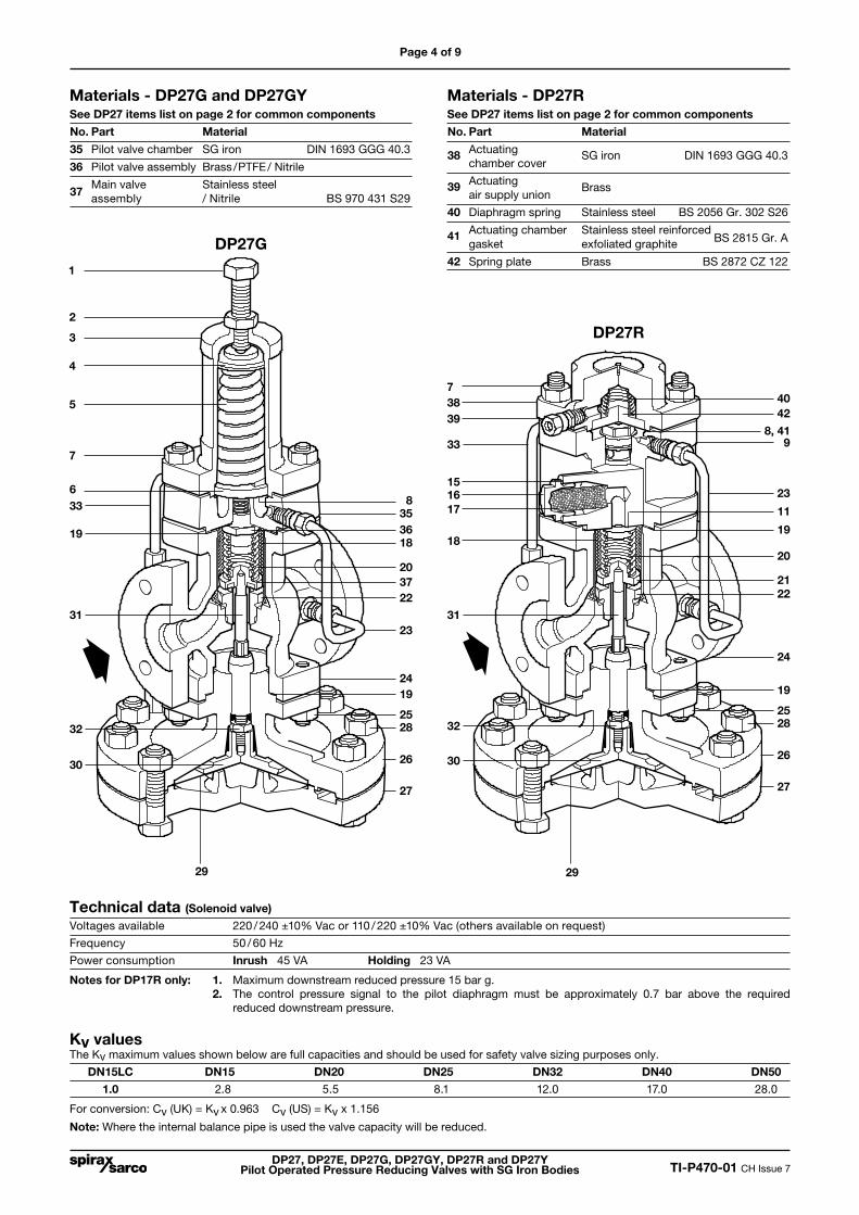
Materials - DP27G and DP27GYSee DP27 items list on page 2 for common components
No. Part Material
35 Pilot valve chamber SG iron DIN 1693 GGG 40.3
36 Pilot valve assembly Brass /PTFE / Nitrile
37 Main valve Stainless steel
assembly / Nitrile BS 970 431 S29
Materials - DP27RSee DP27 items list on page 2 for common components
No. Part Material
38 Actuating SG iron DIN 1693 GGG 40.3 chamber cover
39 Actuating Brass air supply union
40 Diaphragm spring Stainless steel BS 2056 Gr. 302 S26
41 Actuating chamber Stainless steel reinforced gasket exfoliated graphite BS 2815 Gr. A
42 Spring plate Brass BS 2872 CZ 1221
2
5
4
7
6833
31
32
30
23
22
2528
26
27
3
19
29
353618
2037
24
7
8, 4133
31
32
30
22
2528
26
27
19
29
11
19
20
21
24
15
17
18
23
9
19
39
4038
DP27G
DP27R
16
42
Technical data (Solenoid valve)
Voltages available 220 / 240 ±10% Vac or 110 / 220 ±10% Vac (others available on request)
Frequency 50 / 60 Hz
Power consumption Inrush 45 VA Holding 23 VA
Notes for DP17R only: 1. Maximum downstream reduced pressure 15 bar g. 2. The control pressure signal to the pilot diaphragm must be approximately 0.7 bar above the required reduced downstream pressure.
Kv valuesThe Kv maximum values shown below are full capacities and should be used for safety valve sizing purposes only.
DN15LC DN15 DN20 DN25 DN32 DN40 DN50
1.0 2.8 5.5 8.1 12.0 17.0 28.0
For conversion: Cv (UK) = Kv x 0.963 Cv (US) = Kv x 1.156
Note: Where the internal balance pipe is used the valve capacity will be reduced.

Page 5 of 9
DP27, DP27E, DP27G, DP27GY, DP27R and DP27Y Pilot Operated Pressure Reducing Valves with SG Iron Bodies TI-P470-01 CH Issue 7
Dimensions / weights (approximate) in mm and kg
AA1
D
E
F
B
DP27G and DP27GY Screwed Flanged BS 10 H PN16/25 ASME 300 BS 10 F ASME 150 JIS 10/16 Weight Size A A1 A1 A1 A1 A1 A1 B D E F Screwed FlangedDN15 160 - 130 126.6 117 120.2 122 185 364 234 130 12.0 12.8DN20 160 - 150 - 133 139.4 142 185 364 234 130 12.0 13.7DN25 180 160 160 160.0 - 160.0 152 207 388 240 148 13.0 16.0DN32 - 180 180 180.0 - 176.0 176 207 388 240 148 - 17.0DN40 - 200 200 200.0 - 199.0 196 255 433 255 178 - 29.0DN50 - 230 230 230.0 - 228.0 222 255 433 255 178 - 31.5
DP27R Screwed Flanged BS 10 H PN16/25 ASME 300 BS 10 F ASME 150 JIS 10/16 Weight Size A A1 A1 A1 A1 A1 A1 B D E F Screwed FlangedDN15LC 160 - 130 126.6 117 120.2 122 185 296 166 130 12.2 13.0DN15 160 - 130 126.6 117 120.2 122 185 296 166 130 12.2 13.0DN20 160 - 150 - 133 139.4 142 185 296 166 130 12.2 13.9DN25 180 160 160 160.0 - 160.0 152 207 320 172 148 13.2 16.2DN32 - 180 180 180.0 - 176.0 176 207 320 172 148 - 16.2DN40 - 200 200 200.0 - 199.0 196 255 364 186 178 - 29.2DN50 - 230 230 230.0 - 228.0 222 255 364 186 178 - 31.7
DP27, DP27E and DP27Y
DP27G and DP27GY
DP27R
AA1
D
E
F
B
AA1
D
E
F
B
DP27, DP27E and DP27Y Screwed Flanged BS 10 H PN16/25 ASME 300 BS 10 F ASME 150 JIS 10/16 Weight Size A A1 A1 A1 A1 A1 A1 B D E F Screwed FlangedDN15LC 160 - 130 126.6 117 120.2 122 185 406 276 130 13.2 14.0DN15 160 - 130 126.6 117 120.2 122 185 406 276 130 13.2 14.0DN20 160 - 150 - 133 139.4 142 185 406 276 130 13.2 14.9DN25 180 160 160 160.0 - 160.0 152 207 430 282 148 14.2 17.2DN32 - 180 180 180.0 - 176.0 176 207 430 282 148 - 18.2DN40 - 200 200 200.0 - 199.0 196 255 475 297 178 - 30.2DN50 - 230 230 230.0 - 228.0 222 255 475 297 178 - 32.2

DP27, DP27E, DP27G, DP27GY, DP27R and DP27Y Pilot Operated Pressure Reducing Valves with SG Iron Bodies TI-P470-01 CH Issue 7
Page 6 of 9
NoteThe capacities quoted above are based on valves fitted with an external pressure sensing pipe. Reliance on the internal pressure sensing pipe will mean that capacities may be reduced. In the case of low downstream pressure this reduction could be up to 30% of the valve capacity.
How to use the chartSaturated steamA valve is required to pass 600 kg/h reducing from 6 bar to 4 bar. Find the point at which the curved 6 bar upstream pressure line crosses the horizontal 4 bar downstream pressure line. A perpendicular dropped from this point gives the capacities of all DP sizes under these conditions. A DN32 valve, is the smallest size which will carry the required load.
Superheated steamBecause of the higher specific volume of superheated steam a correction factor must be applied to the figure obtained from the chart above. For 55°C of superheat the factor is 0.95 and for 100°C of superheat the factor is 0.9.Using the example given for saturated steam, the DN32 valve would pass 740 x 0.95 = 703 kg/h if the steam had 55°C of superheat. It is still big enough to pass the required load of 600 kg/h.
Steam capacities chart
��
��
��
��
�
�
�
�
�
�� ��� ��� ���
��� ��� ��� ��� ���
��� ��� ��� ��� ����
��� ��� ���� ����
���� ����
���� ���� ����
���� ���� ���� ���� ���� ����
� � � � � �� �� �� �� ��
DN15LC
DN15
DN20
DN25
DN32
DN40
DN50
Dow
nstr
eam
pre
ssur
e b
arC
apac
ity k
g / h
Upstream pressure bar
* Note: The DP27E is limited to 10 bar.
*

Page 7 of 9
DP27, DP27E, DP27G, DP27GY, DP27R and DP27Y Pilot Operated Pressure Reducing Valves with SG Iron Bodies TI-P470-01 CH Issue 7
�� ��� ���
��� ��� ���
��� ��� ��� ���
��� ��� ���
��� ��� ���� ���� ����
���� ����
���� ���� ���� ���� ����
��� ��� ��� ���
��� ��� ��� ���
��� ��� ���
���� ���� ����
�� �� �� �� �� �� �� �� ��
���� ����
��
��
���
���
���
���
��
���
���
���
���
����
�� ��
�� ���
��� ���
��� ���
��� ���
��
��
��
��
�
�
�
�
�� � � � �
��
��
��
��
����
How to use the chartCapacities are given in cubic decimetres of free air per second (dm3/s). The use of the capacity chart can be best explained by an example. Required, a valve to pass 100 dm3/s of free air reducing from 12 bar to 8 bar. Find the point at which the curved 12 bar upstream pressure line crosses the horizontal 8 bar downstream pressure line. A perpendicular dropped from this point shows that whereas a DN15LC valve will only pass 57 dm3/s and is therefore not large enough, a DN15 valve will pass approximately 120 dm3/s under these conditions and is the correct valve size to choose.
Safety information, installation and maintenanceFor full details see the Installation and Maintenance Instructions (IM-P100-05 for the DP27G and DP27GY, or IM-P470-03 for the DP27E, DP27R and DP27Y) supplied with the product.
Installation note: The pilot operated pressure reducing valve should be installed in a horizontal pipeline, protected by a strainer and a separator, with the direction of flow as indicated by the arrow on the valve body.
How to order example:1 off Spirax Sarco DN32 DP27 pilot operated pressure reducing valve having a 0.2 - 17 bar spring and flanged EN 1092 PN25 connections.
Compressed air capacities chart
DN15LC
DN15
DN20
DN25
DN32
DN40
DN50
Dow
nstr
eam
pre
ssur
e b
arC
apac
ity d
m3/s
free
air
Upstream pressure bar
DP27, DP27E, DP27G, DP27GY, DP27R and DP27Y Pilot Operated Pressure Reducing Valves with SG Iron Bodies TI-P470-01 CH Issue 7
Page 8 of 9
*
**
*
*
*
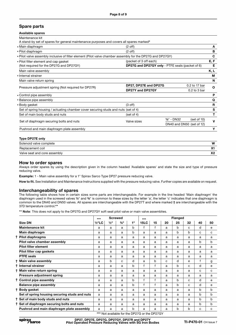
Spare partsAvailable spares
Maintenance kit A stand-by set of spares for general maintenance purposes and covers all spares marked*
Main diaphragm (2 off) A
Pilot diaphragm (2 off) B
Pilot valve assembly inclusive of filter element (Pilot valve chamber assembly for the DP27G and DP27GY) C
Pilot filter element and cap gasket (packet of 3 off each) E, F(Not required for the DP27G and DP27GY) DP27G and DP27GY only - PTFE seals (packet of 6) E
Main valve assembly K, L
Internal strainer M
Main valve return spring N
Pressure adjustment spring (Not required for DP27R) DP27, DP27E and DP27G 0.2 to 17 bar
O DP27Y and DP27GY 0.2 to 3 bar
Control pipe assembly P
Balance pipe assembly Q
Body gasket (3 off) R
Set of spring housing / actuating chamber cover securing studs and nuts (set of 4) S
Set of main body studs and nuts (set of 4) T
Set of diaphragm securing bolts and nuts Valve sizes ½" - DN32 (set of 10)
V DN40 and DN50 (set of 12)
Pushrod and main diaphragm plate assembly Y
Type DP27E only
Solenoid valve complete W
Replacement coil X1
Valve seat and core assembly X2
How to order sparesAlways order spares by using the description given in the column headed 'Available spares' and state the size and type of pressure reducing valve.
Example: 1 - Main valve assembly for a 1" Spirax Sarco Type DP27 pressure reducing valve.
How to fit. See Installation and Maintenance Instructions supplied with the pressure reducing valve. Further copies are available on request.
Interchangeability of spares The following table shows how in certain sizes some parts are interchangeable. For example in the line headed 'Main diaphragm' the diaphragm used in the screwed valves ½" and ¾" is common to these sizes by the letter 'a', the letter 'c' indicates that one diaphragm is common to the DN40 and DN50 valves. All spares are interchangeable with the DP27T and where marked † are interchangeable with the 37D temperature control.**
** Note: This does not apply to the DP27G and DP27GY soft seat pilot valve or main valve assemblies.
Screwed Flanged
Size DN ½"LC ½" ¾" 1" 15LC 15 20 25 32 40 50
Maintenance kit a a a b f f a b c d e
Main diaphragm a a a b a a a b b c c
Pilot diaphragms a a a a a a a a a a a
Pilot valve chamber assembly a a a a a a a a a b b
Pilot filter element a a a a a a a a a a a
Pilot filter cap gaskets a a a a a a a a a a a
PTFE seals a a a a a a a a a a a
Main valve assembly a b c d a b c d e f g
Internal strainer a a a b f f a b c d e
Main valve return spring a a a a a a a a a c c
Pressure adjustment spring a a a a a a a a a a a
Control pipe assembly a a a b f f a b c d e
Balance pipe assembly a a a b f f a b c d e
Body gasket a a a a a a a a a b b
Set of spring housing securing studs and nuts a a a a a a a a a b b
Set of main body studs and nuts a a a a a a a a a b b
Set of diaphragm securing bolts and nuts a a a a a a a a a b b
Pushrod and main diaphragm plate assembly a a a b a a a b b c c
†
††
†
†
†
††
*** ***
*
*
*** Not available for the DP27G or the DP27GY

Page 9 of 9
DP27, DP27E, DP27G, DP27GY, DP27R and DP27Y Pilot Operated Pressure Reducing Valves with SG Iron Bodies TI-P470-01 CH Issue 7
So
lenoid
valve com
plete
X1
X2
N
K
L
Mai
n va
lve
asse
mb
ly
O
YM
V
A
Q
R
V
T
S
E
F
P
R
B
C
S
W
T
DP27R
DP27E
S
R
DP27G, DP27GY
E
DP27, DP27G, DP27GY, DP27Y
DP27E
C
C