dr-c50 series user configurable solution · pdf fileuser configurable solution for transformer...
TRANSCRIPT
1www.dynamicra tings.com
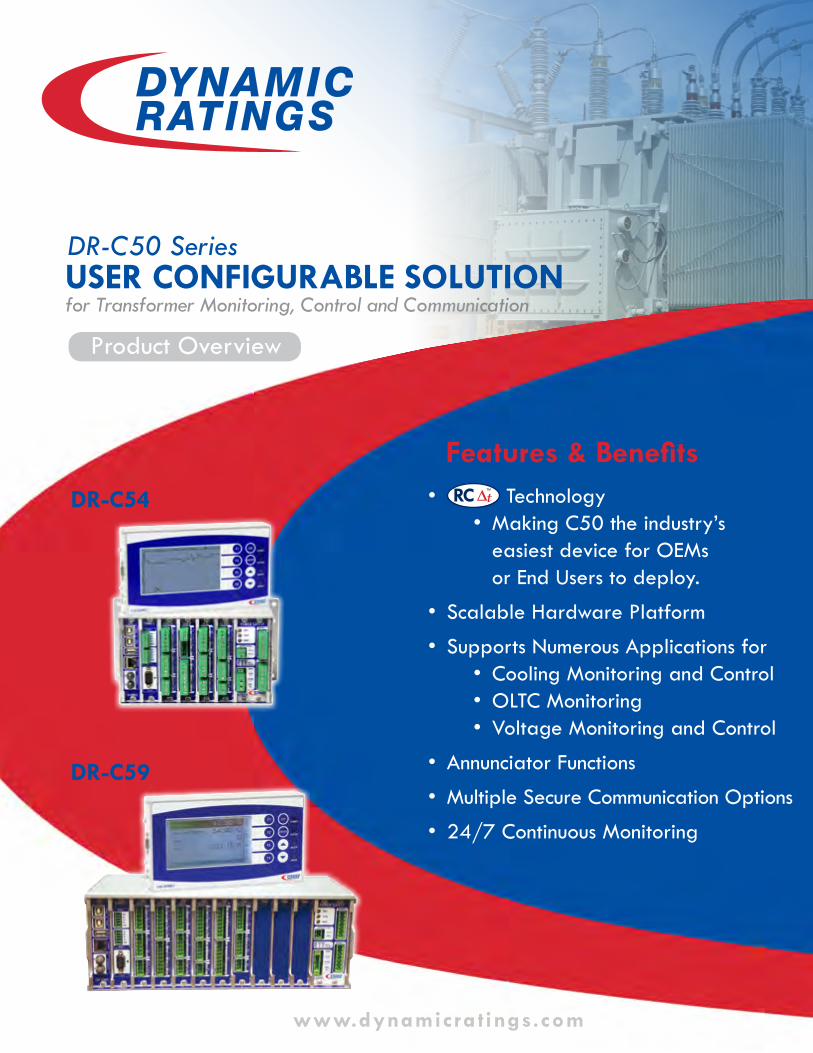
USER CONFIGURABLE SOLUTIONfor Transformer Monitoring, Control and Communication
Product Overview
DR-C54
DR-C50 Series
DR-C59
Features & Benefits• RC TM Technology
• Making C50 the industry’s easiest device for OEMs or End Users to deploy.
• Scalable Hardware Platform
• Supports Numerous Applications for• Cooling Monitoring and Control• OLTC Monitoring • Voltage Monitoring and Control
• Annunciator Functions
• Multiple Secure Communication Options
• 24/7 Continuous Monitoring
2
Features & Benefits ¾ Configure the C50 Series Monitor to your unique
application using the included Initial Configurator software.
¾ Log in to the Web Dashboard to securely monitor your asset’s history and condition.
¾ Modular hardware platform allows for a broad variety of applications and on-site upgrades by the user.
¾ Programmable functions for cooling and voltage control, enabling fast, automatic response to alarms.
RC TM is a registered trademark of Dynamic Ratings.
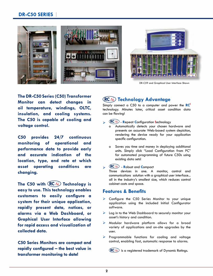
The DR-C50 Series (C50) Transformer Monitor can detect changes in oil temperature, windings, OLTC, insulation, and cooling systems. The C50 is capable of cooling and voltage control.
C50 provides 24/7 continuous monitoring of operational and performance data to provide early and accurate indication of the location, type, and rate at which asset operating conditions are changing.
The C50 with RCTM
Technology is easy to use. This technology enables customers to easily configure a system for their unique application, rapidly present data, notices, or alarms via a Web Dashboard, or Graphical User Interface allowing for rapid access and visualization of collected data.
C50 Series Monitors are compact and rapidly configured – the best value in transformer monitoring to date!
RC TM
Technology AdvantageSimply connect a C50 to a computer and power the RCt
technology. Minutes later, critical asset condition data can be flowing!
¾ RC TM
- Repeat Configuration technologyo Automatically detects your chosen hardware and
presents an accurate Web-based system depiction, rendering the device ready for your application specific configuration.
o Saves you time and money in deploying additional units. Simply click “Load Configuration from PC” for automated programming of future C50s using existing data sets!
¾ RC TM - Robust and CompactThree devices in one. A monitor, control and communications solution with a graphical user interface... all in the industry’s smallest size, which reduces control cabinet costs and space.
DR-C59 and Graphical User Interface Shown
DR-C50 SERIES |

3
DR-C50 SERIES | Features
Control
• Cooling Control
º Load Activated, Cooling Turn On
º Fail-Safe Configurable
º Fan Sequencing º Fan/Pump Test
• Voltage Control
º Paralleling Options - Master/Follower - Reverse
Reactance º LDC º Voltage Graphing
Display
• Temperatures
º Top Oil
º Bottom Oil
º Winding Hot Spots
º Ambient
• Cooling System
º Fan/Pump Current
º Contactor Status
º Loss of Power
• DGA & Moisture
º Serial or Ethernet Link to Third Party Dissolved Gas Analyzers (DGA)*
• OLTC
º Position
º Operation Counters
º OLTC Temperature Differential
º Motor Current
º Contact Wear
º Reversing Switch Operation
º Hunting
• Alarms
º Built-in Annunciator
º Major/Minor Groups
• Data Logging
º Chronological Data Log
º Alarm Log
Monitoring per IEC and ANSI/IEEE standards
* Consult the factory for a list of compatible devices.
• SCADA Connections
º Serial (Half or Full Duplex) - Fibre, RS-485, RS-232 - Protocols: DNP 3.0, Modbus
º Ethernet - Copper, 10/100 Base T; Fiber,
100 Base FX; Ethernet over USB - Protocols: IEC-61850, DNP 3.0, Modbus
º SCADA Test Utility
• iBridge IED Networking Solution Capable
• Ethernet Switch Function
º Provides simultaneous copper and fibre connection
Communications multiple secure options
Three-in-One Monitor, Control, and Communications Solution
Messaging and Alarming
Ambient & Operating
Temperatures
Cooling SystemOLTC
IEDs Inclusive of DGA
Bushing
Critical Operating and Performance Data
DR-C50
Transformer Asset Health Monitor
iBridge IED Networking Solution - Use existing wire for data flow!
1
2
3

4
Easy InstallationThe C50 Configurator software is compatible with Windows computers and typically downloads directly to your computer from the DR-C50 Monitor via a USB Ethernet connection - no Internet access required.
Four Easy Steps to Monitoring Your Assets
Transformer monitoring is made easy for OEMs and End Users, simply connect a C50 to a computer and power the RC
TM Technology.
Launch the Configurator
DR-C50 SERIES | Monitoring Made Easy
Connect Configure Upload Monitor
Connect the C50 to your computer. Download
and install drivers and configuration software.
Configure the C50 using RC TM Technology.
Upload your application-specific
monitor configuration.
Monitor your asset.
1 2 3 4
To launch the Initial Configurator, open the Start Menu and run
Configurator.

5
DR-C50 SERIES | Ease of Configuration
Intuitive Configuration Screens
The Configurator allows for programming incremental devices using previously created DR-C50 configurations.
Copy existing application configurations to your 2nd, 3rd, etc. asset monitor.
Configuration screens provide easy-to-use, intuitive windows and menus.
RC TM technology determines what to ask about your transformer and its use, saving time and avoiding confusion by focusing only on information relevant to your application.
The Configurator allows tailoring to your application.
Save Time With Automated Configuration
RC TM technology ensures you only program the attributes relevant to your application create new configuration files or copy prior configurations. This allows for rapid configuration and deployment of large-scale applications.
Automating Configuration
Create application specific configurations for new monitoring systems.
To load the device’s configuration or create new configurations,
click .
To copy prior configurations, click .
Configuration windows for each installed module provide clear and concise configuration selections. By clicking the module’s graphic, you are able to configure the device for your application.
Click a module Tailor to your application Apply changes

6
DR-C50 SERIES | Monitoring Dashboard
The C50 Monitoring Dashboard is a powerful tool for managing and monitoring your assets. Logging in to the monitor via a web browser, operators can view the current status of the devices being monitored and alarm history.
The main dashboard provides navigation toolbars and critical electrical, temperature, and alarm status overviews. The dashboard monitoring tab allows for detailed visual presentations of vital operating conditions of your transformer.
Monitoring Dashboard features:
• Real-time at-a-glance load and temperature data• Configuration of custom alarms• Customized data logging• GUI-based configuration of the control unit• Configuration of digital output for application-specific
control mechanisms• Secure remote access• OLTC Monitoring• Voltage ControlEase of Navigation
View Alarms
View Electrical Data Measured and Calculated Temperatures
Tap Wear Data
Bushing Health
DGA IED Data
Review Real Time DataThe dashboard provides real time data to track alarms, view data history, and configure responses and reactions to changing conditions of your transformer
Monitoring Dashboard
Main Dashboard

7
DR-C50 SERIES | Hardware Overview
The C50 Series is a scalable system. The basic components of each system are a Control Unit and a Graphical User Interface (GUI).
Control UnitThe DR-C50 monitoring system is offered in two frame sizes:
o DR-C54, supports up to four expansion cardso DR-C59, supports up to nine expansion cards
Each C50 control unit is comprised of the following:• 1 x expansion rack (Two frame sizes are offered)• 1 x CPU module• 1 x Communications module• 1 or more I/O modules (user selectable expansion cards)• 1 x Universal Input, Power Supply module
Electrical connections are made using terminal blocks that can be unplugged to facilitate testing, rewiring, or replacement of hardware.
C50 controls feature RCTM technology. This technology allows each control unit to perform various self-checks when
it turns on. Additionally, during power up the RCTM technology automatically detects installed expansion hardware
selections and prepares data sets for configuration. This accurate system depiction makes the device ready for your application specific configuration.
C59C54
The GUI can be mounted in several manners: panel, DIN rail, or 19 inch rack mount installation. Each GUI ships with the hardware required for all methods above. Rack mount plate shown below.
Graphical DisplayData is presented in a graphical format to easily interpret and diagnose trends.
Voltage and control settings are drawn graphically for easier system testing.
Smart Menu ButtonsOne touch buttons (F1-F4) immediately access functionality.
Navigate menus with Esc, Enter, and up or down scrolling.
System Status LEDsProvide quick status indication.
Graphical User Interface
Hardware Overview
The GUI connects to the control using the provided cable terminated with DB9 connectors. The inter-connection cable carries the keypad signals, LCD data information, and the 24V power supply source.

8
Base A: 2× Form A Relay Outputs + 1× Form B + 2× Form C + 2× DC Analog Inputs/Outputs
Base B:
3× RTD Inputs + 4× CT Inputs
CPU & Ethernet Card Communications Card Base System Cards (see Relay Definitions) Select from Base A or Base B Cards providing:
2× RS-485 Connections for SCADA or other serial device connections. These EIA compatible connectors can be either two wire or four wire
Optional Serial Port • Serial Fibre Optic • RS-232 (shown) • RS-485
1× USB Type B Console Port1× USB Type B Device Port
(Configuration/Setup)1× USB Type A Host Port
(Data Download)1× 10/100 Base T
RJ45 Ethernet1× Fibre Ethernet Connection
100 Base FX
Universal Power SupplyStatus LEDs: DRMCC, System, and Power Electrically isolated 24v DC output supplies up to 250mA for digital inputs.Input Power:88-288 VDC88-276 VAC 50/60 Hz
Breakout 1 and 2 supply voltage to digital input devices.
Optional Expansion Cards (see relay definitions)
Select from the following card options for slots 1-9. Select one Voltage Control card. Select one OLTC Monitoring card.
N - NoneA - Base A, (Two Form A Relay Outputs + One Form B
+ Two Form C + Two DC Analog Inputs/Outputs)B - Base B, (Three RTD Inputs + Four CT Inputs)C - Digital Input (Thirteen Digital Inputs)D - Digital Output (Five Form C Relay Outputs)E - Voltage Control (One Voltage Transformer (VT) Input
+ Three CT Inputs + Three Digital Inputs + Two Form A Outputs)
F - OLTC Monitoring (Two RTD Inputs + Four Digital Inputs + OLTC Motor Current)
G - Bushing Health Monitoring (Six BAU Sensor Inputs)
System Frame Options• DR-C54 Provides four card slots for
optional expansion cards (Slots 1-4)
• DR-C59 Provides nine card slots for optional expansion cards (Slots 1-9)
31 42
5 76 8 921 3 4
Relay DefinitionsForm A = SPST-NO. A single, normally open contact that closes upon actuation.
Form B = SPST-NC. A single, normally closed contact that opens upon actuation.
Form C = SPDT. A Form A contact connected to a Form B. The Form C contact has three wires, NO (normally open), NC (normally closed) and C (common) Upon actuation, the NO contact closes (continuity from NO-C) and the NC contact opens (no continuity from NC-C).
Powerful Monitoring Options
DR-C50 SERIES | Hardware Overview

9
DR-C50 SERIES | Packaging Options
Packaging OptionsThe DR-C50 may be ordered as a standalone instrument, or in an enclosure with or without iBridge communications.
All models ship with installation drill templates.
Standalone (S) Enclosure With Communications (C)
Enclosure Mounted (E)
Includes:• Monitoring Instrument Populated
with Connectors • Graphical User Interface with
Connection Cable• Configuration software• USB Configuration Cable
Includes Option (E) and:• iBridge Communications Device
Includes Option (S) and:• NEMA 4x Enclosure
DR-C54
Overall Dimensions and Mounting Hole Locations30.5 cm / 12 in.
42.54 cm16.75 in.
25.4 cm / 10 in.
40.6 cm 16 in.
22.9
cm9
in.
C54 Enclosure (E or C)
61 cm / 24 in.
57.15 cm22.5 in.
57.2 cm / 22.5 in.
61 cm 24 in.
25.4
cm
10 in
.
C59 Enclosure (E or C)
24.8 cm / 9.8 in.
12.6 cm5 in.
11.1 cm4.37 in.
14.26
cm
5.6 in
.
23.2 cm / 9.13 in.
C54 Standalone (S)
37.4 cm / 14.7 in.
12.6 cm5 in.
11.1 cm4.37 in.
14.26
cm
5.6 in
.
35.8 cm / 14.1 in.
C59 Standalone (S)
DR-C54
DR-C59
DR-C54
For other enclosure options, please contact the factory.

10
DR-C50 SERIES | Ordering Guide
Microsoft Windows® is a registered trademark of Microsoft Corporation
DR-C50 – ORdERING INFORmATION
To Order, Fill Boxes with Feature Selections
Optional Expansion Cards (see relay definitions)
N
A
B
C
D
E1
F2
G3
None. (Each N will include one blank slot cover.)
Base A: Two Form A Relay Outputs + One Form B + Two Form C + Two DC Analog Inputs/Outputs.
Base B: Three RTD Inputs + Four CT Inputs.
Digital Input: Thirteen Digital Inputs.
Digital Output: Five Form C Relay Outputs.
Voltage Control: One Voltage Transformer (VT) Input + Three Current Transformer (CT) Inputs + Three Digital Inputs + Two Form A Outputs.
OLTC Monitoring: Two RTD Inputs + Four Digital Inputs + OLTC Motor Current.
All base systems include one of each of the following: CPU, Ethernet Card with 10/100 Base T (RJ45) and Fiber Optic (100 Base FX), Communications Option including two RS-485 Ports, Power Supply, Graphic User Interface with Cable, USB A to USB B Cable, and a quick-start booklet.
Packaging OptionsStand-alone. Ready for DIN rail or panel mounting. Included is a Graphical User Interface 48 cm / 19 in. rack mounting plate.
Base System, NEMA 4x Enclosure Mounted
S
E
C Base System, NEMA 4x Enclosure Mounted with one CE-525 iBridge Communication Device, one IND2000N signal coupler, one Ethernet cable, and one mounting bracket.
Serial Communications Options04
124
Two RS-485 Ports (factory default)Two RS-485 Ports + Serial Fiber OpticTwo RS-485 Ports + RS-232Three RS-485 Ports
DR-C5 - - -
Sele
ct Ba
se S
yste
m T
ype
Sele
ct a
Pack
agin
g O
ptio
n
Sele
ct Se
rial
Com
mun
icatio
n O
ptio
n
Expansion Cards1 2 3 4 5 6 7 8 9
0124
S
E
C
N
A
B
C
D
E
F
G
Base System49
Base System + Select up to four optional expansion cards.Base System + Select up to nine optional expansion cards.
49
Notes 1 Select no more than one Voltage Control Card per system2 Select no more than one OLTC Monitoring Card per system.3 Select no more than one Bushing Health Monitoring Card per system.
Cables, sensors, and wiring are not included and must be ordered separately.
4 Every base system includes a Serial Communications card, providing two RS-485 ports.
Bushing Health Monitoring: Six BAU Sensor Inputs
N
A
B
C
D
E
F
G
N
A
B
C
D
E
F
G
N
A
B
C
D
E
F
G
N
A
B
C
D
E
F
G
N
A
B
C
D
E
F
G
N
A
B
C
D
E
F
G
N
A
B
C
D
E
F
G
N
A
B
C
D
E
F
G

11
DR-C50 SERIES | System Specifications and Accessories
SPECIFICATIONSPower Requirement: 88 - 288 VDC or 88 - 276 VAC 50/60 HzInternal Memory: 2 GBTemperature Range: - 40°C to + 70°C / - 40°F to + 158°FUser Interface: Backlit LCD (Daylight Readable) connected via supplied cable.
SENSORS – ORdERING INFORmATION
CT-054 Auxiliary CT: Split Core CT 1000:1 Ratio w/5A PrimaryCT-055 Auxiliary CT: Fixed Core CT 1000:1 Ratio w/5A PrimaryMMTS-3C Temperature Sensor, RTD - Magnetic Mount w/ 1/2” NPT Thermal WellMMTS-3W Temperature Sensor, RTD - Magnetic Mount w/ 7.6m (25ft.) S/S CableSE-060 Temperature Sensor, Probe for 1/2” NPT Thermal WellSE-065 Temperature Sensor, Dual element probe for 1/2” NPT Thermal WellSE-070 Ambient Temperature RTD with Weather Shield AssemblySE-075 Ambient Temperature RTD with fitting for enclosure mounting
Part # Description
Part #iBridge DEVICES and ACCESSORIES – ORdERING INFORmATION
CE-520 iBridge with a 1.83m / 6 ft. power cord with NEMA 5-15 plugCE-525 iBridge with a field wiring plugCE-530 Gateway with a 1.83m / 6 ft. power cord with NEMA 5-15 plugCE-535 Gateway with field wiring plugCE-562 One RS-232 connection adaptorCE-564 One RS-232 (25 pin) connection adaptorIND2000N One 9mm / 0.35 in. signal couplerIND2020N One 13mm / 0.51 in. signal couplerIND2040N One 18mm / 0.71 in. signal couplerIND2100N One 25mm / 0.98 in. signal couplerSLRS5DIN00RXX iBridge mounting kit includes: (1) DIN mount L-bracket and hardware
Description
CT-054 CT-055 MMTS-3W SE-060 SE-070
iBridge CE-520
iBridge CE-525
CE-562
CE-564
IND-; 2000N, 2020N, 2040N, 2100NSLRS5DIN00RXX iBridge Mounting L-bracket, iBridge on Mounting Kit

For any enquiry, please contact your local Dynamic Ratings office.
©2016 Dynamic Ratings Specifications subject to change without notice. All rights reserved. DR-C50 160727
Asia / Africa / Oceania +61 3 9574 7722 [email protected] / Europe +1 262 746-1230 [email protected]
www.dynamicratings.com