dr maksym spiryagin - cquniversity - module 3: suspension designs to optimize curving and hunting
TRANSCRIPT

Design
Module 3 - Locomotive suspension
Dr Maksym Spiryagin, Centre for Railway Engineering, CQUniversity
Tuesday 20 May 2014
Brisbane

Module 3: Locomotive Suspension
Contents
• Bogies
• Traction drives
• Suspension and its elements
• Active suspension
• Connection between a locomotive frame and bogies
• Steering bogies
• Example of studies on locomotive suspension systems

Bogies
A critical function of the bogie is to improve
the dynamic interaction between the running
gear and the rails in curved sections of
track.
The rail vehicle bogie provide support or
suspension for weight of the upper structure
(above the bogie, i.e., the car body) and
redistributes it between the wheels or
wheelsets through the elastic-damping
connection, and also transmits the traction
and braking forces to the upper structure
and coupling devices.
Three-axle bogie [1] of
a heavy haul locomotive (Goninan, Australia)
1 – sidebearing; 2 – brake cylinder; 3 – wheelset;
4 – traction motor; 5 – axle box; 6 – damper;
7 – coil spring; 8 – yoke for the centre pin;
9 – sand box; 10 – sand trap.

Traction drives
Designs of drives are varied and depend on the type and operational service
parameters of rail traction vehicles, the selected mode of transmission, the
design of wheelsets/wheels and the mounting methods of the traction motor.
The traction drive designs can be divided into two types[1]:
• individual;
• grouped.
The design and parameters of traction drives are often dependent on the
installation designs of traction motors and associated gearing. Three design
variants have found wide application[1]:
• with a nose-suspended traction motor;
• with a frame-mounted traction motor;
• with a body-mounted traction motor.

Suspension and its elements
The following classification by elements can be made[1]:
• leaf spring suspension;
• helical (or coil) spring suspension;
• air spring suspension;
• hydraulic suspension;
• electromechanical suspension;
• dampers;
• combination of several suspension elements;
• active suspension.

Active suspension
Active suspension systems can be classified by their main functions[1]:
• active damping;
• active steering;
• active tilting in curves;
• load transfer between wheels (or wheelsets) and bogies.

Connection between a locomotive frame and bogies
Such connection can be also classified
by elements used as follows[1]:
• centre pivots;
• side bearers;
• links and linkages;
• traction rods.Connection elements mounted on the bogie frame
(EMD GM, USA) [1]
1 – yoke; 2 – frame;
3 – traction rod; 4 – sidebearing.
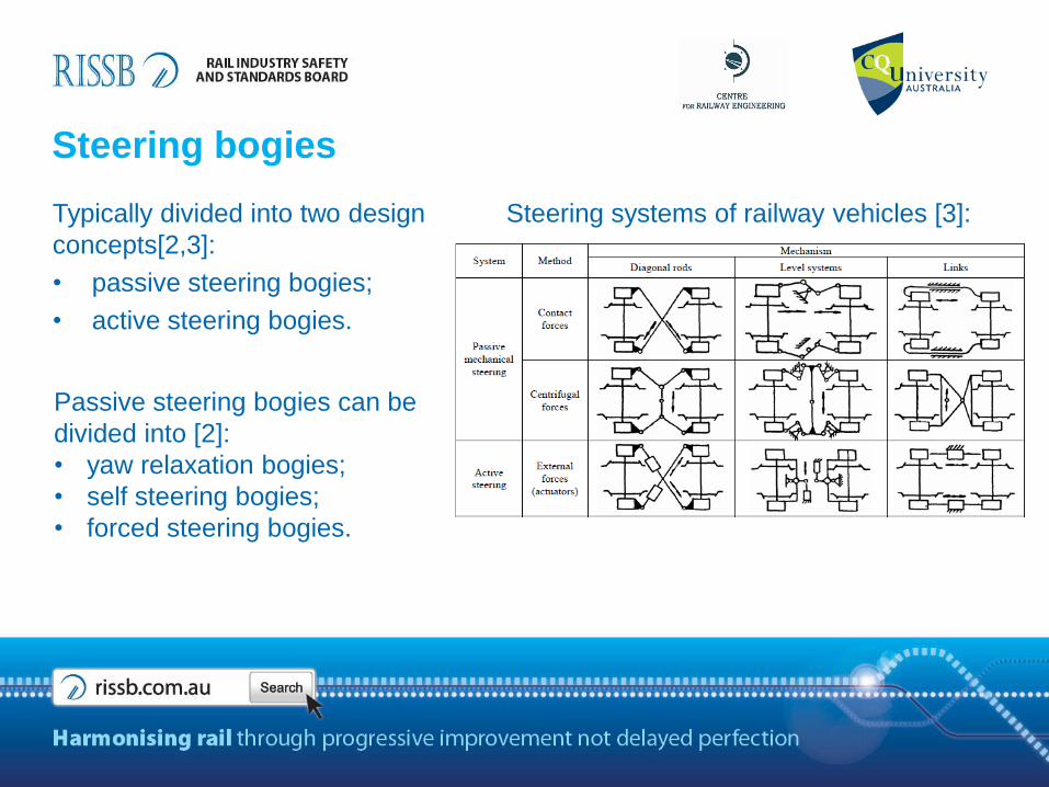
Steering bogies
Typically divided into two design
concepts[2,3]:
• passive steering bogies;
• active steering bogies.
Passive steering bogies can be
divided into [2]:
• yaw relaxation bogies;
• self steering bogies;
• forced steering bogies.
Steering systems of railway vehicles [3]:
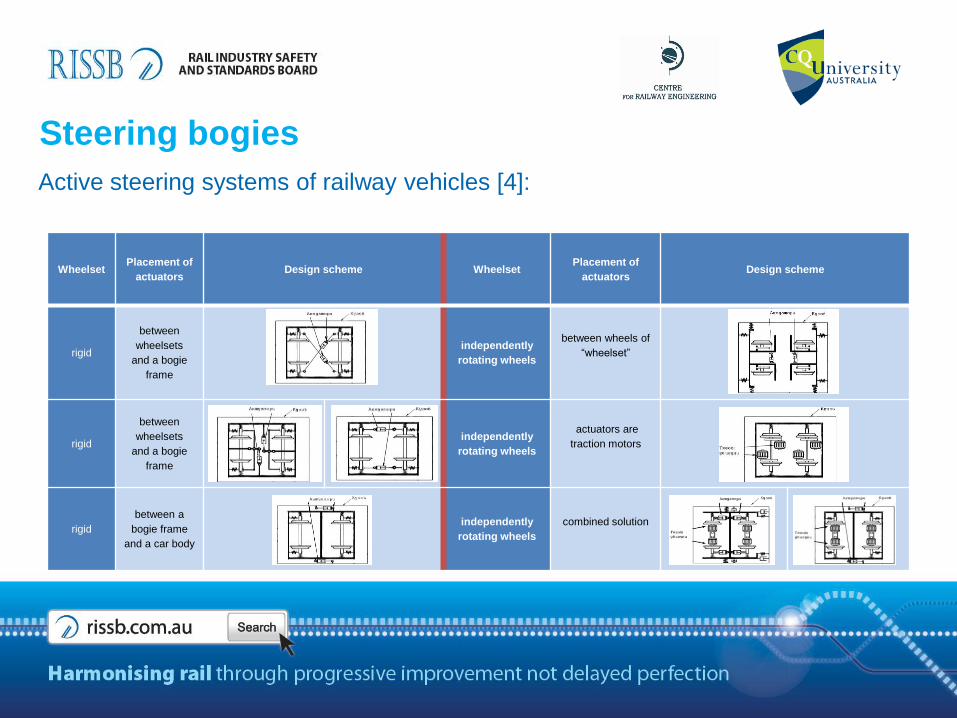
Steering bogies
Active steering systems of railway vehicles [4]:
WheelsetPlacement of
actuatorsDesign scheme Wheelset
Placement of
actuatorsDesign scheme
rigid
between
wheelsets
and a bogie
frame
independently
rotating wheels
between wheels of
“wheelset”
rigid
between
wheelsets
and a bogie
frame
independently
rotating wheels
actuators are
traction motors
rigid
between a
bogie frame
and a car body
independently
rotating wheels
combined solution

Example of studies on locomotive suspension systems
Objectives of this study [5]:
• primary suspension design of heavy haul locomotive;
• influence of varying installation angles of the traction rod on the angle of attack
results for the non-traction and traction modes.
Primary suspension design Multibody model in Gensys
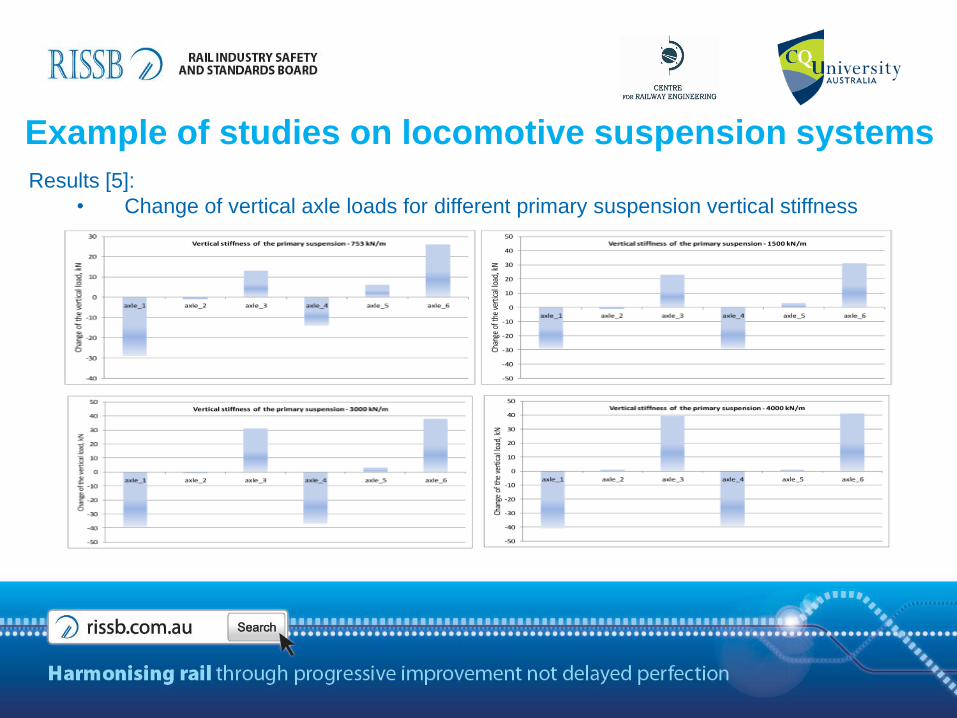
Example of studies on locomotive suspension systems
Results [5]:
• Change of vertical axle loads for different primary suspension vertical stiffness

Example of studies on locomotive suspension systems
Results [5]:
• Angle of attack results for the non-traction and traction modes for varying installation
angles of the traction rod

Example of studies on locomotive suspension systems
Discussion
• varying the values of vertical stiffness change the situation of load
distribution between the locomotive axles;
• changing traction rod installation angle can compensate for steering ability
deterioration under high tractive effort conditions;
• the usage of the total stiffness approach during modelling should be
restricted in such studies because it does not allow an adequate judgment to be
made about suspension behaviour.
Conclusion
• the vertical stiffness might have significant effects on the locomotive traction
due to the vertical load distribution between axles;
• the change of installation positions of traction rods is able to improve the
steering ability in the curved parts of track.

References[1] M. Spiryagin, C. Cole, Y. Q. Sun, M. McClanachan, V. Spiryagin, T. McSweeney,
Design and simulation of rail vehicles, Ground Vehicle Engineering Series, CRC Press,
2014. ISBN 978-146-657-566-0.
[2] S. Simson, Three axle locomotive bogie steering, simulation of powered curving
performance. Passive and active steering bogies, Ph.D. thesis, Central Queensland
Universi-ty, Rockhampton, Queensland, Australia, 2009.
[3] M. Spiryagin, K. S. Lee, H. H. Yoo, V. Spiryagin, Y. Vivdenko, Active steering control
system of a rail vehicle based on the analysis of the sound radiation, Noise-Con 2007,
Reno, Nevada, USA, 21-24 October, 2007.
[4] M. Spiryagin, V. Spiryagin, Modelling of mechatronic systems of running gears for a
rail vehicle, East Ukrainian National University, Lugansk, Ukraine, 2010. ISBN 978-966-
590-871-5 (in Ukrainian)
[5] M. Spiryagin, C. Cole, Y.Q. Sun, T. McSweeney, V. Spiryagin, N. Gorbunov, A.
Golubenko, Optimisation of primary suspension characteristics for heavy haul
locomotives, 10th World Congress on Railway Research (WCRR2013), Sydney,
Australia, 25-28 November, 2013.