dr20i4 thru dr600v4, with basler controller, installation & operation manual 2008
TRANSCRIPT
� ���
���������
����
INSTALLATION ANDOPERATIONS MANUAL
DR20 - DR600With DGC-2020Engine Control
DR45I4 Shown for Comparison

Page i
TABLE OF CONTENTS
INTRODUCTION iGUIDE TO PRODUCT SAFETY 1BASIC INFORMATION 2
Description 2DGC-2020 Engine Control Layout 3DGC-2020 Display Operations 5
RECEIVING THE GENERATOR 6Unpacking the unit 6Lifting the unit 7
ENGINE GENERATOR INSTALLATION 7Installation 6Engine Generator Set Mounting 8Fuel Installation 8Lubrication 8Coolant 8Battery Installation 9Battery Charger/Block Heater Wiring 9Mounting The Transfer Switch 10
AC ELECTRICAL CONNECTIONS 10DC ELECTRICAL CONNECTIONS 12INITIAL START-UP 13EXERCISER CLOCK 14TROUBLESHOOTING INFORMATION 14APPENDIX DIRECTORY 15
Appendixes 16-2912 MONTH WARRANTY 30
PROPER USE AND INSTALLATION
You must be sure your new engine generator set is:* Properly serviced before starting* Operated in a well ventilated area* Properly exhausted and gases safely dispersed* Wired by a qualified electrician* Operated only for its designed purposes* Used only by operators who understand its operation* Properly maintained
SAVE THESE INSTRUCTIONSThis manual contains important instructions thatshould be followed during installation and maintenanceof the generator and batteries.
Read and understand all instructions in the manualbefore starting and operating the generator set.
USING THIS MANUAL
Congratulations on your choice of a Winpower genera-tor set. You have selected a high-quality, precision-engi-neered generator set designed and tested to give you yearsof satisfactory standby service.
To get the best performance from your new enginegenerator set, it is important that you carefully read andfollow the operating instructions in this manual.
Should you experience a problem please follow the“Things To Check” near the end of this manual. Thewarranty listed in this manual describes what you canexpect from WINPOWER should you need service assis-tance in the future.
COPY YOUR MODEL AND SERIAL NUMBER HERE
No other WINPOWER generator has the same serialnumber as yours. It is important that you record the num-ber and other vital information here. If you should ever needto contact us on this unit it will help us to respond to yourneeds faster.
MODEL_____________________________________
SERIAL NUMBER____________________________
'M" Spec. __________________________________
PURCHASE DATE____________________________
DEALER____________________________________

60708-142 Page 1 8122-00
2. FIRE HAZARD - Deisel fuel presents a hazard of possibleexplosion and/or fire.
a. Do not smoke or use open flame near the generatorset.
b. Keep a fire extinguisher nearby and know its proper use.Fire extinguishers rated ABC by NFPA are appropriate.
3. DEADLY EXHAUST GAS - Exhaust fumes from any diesel engine contain carbon monoxide, an invisible, odorlessand deadly gas that must be mixed with fresh air.
a. Operate only in well ventilated areas.b. Never operate indoors.c. Never operate the unit in such a way as to allow exhaust
gases to seep back into closed rooms (i.e. throughwindows, walls or floors).
4. NOISE HAZARD - Excessive noise is not only tiring, butcontinual exposure can lead to loss of hearing.
a. Use hearing protection equipment when workingaround this equipment for long periods of time.
b. Keep your neighbors in mind when permanently install-ing this equipment.
5. CLEANLINESS - Keep the generator and surrounding areaclean.
a. Remove all grease, ice, snow or materials that createslippery conditions around the unit.
b. Remove any rags or other material that could createpotential fire hazards.
c. Carefully wipe up any fuel or oil spills before starting theunit.
d. Never allow leaves or other flammable material to buildup around the engine exhaust area.
6. SERVICING EQUIPMENT - All service, including theinstallation or replacement of service parts, should beperformed only by a qualified technician.
a. Use only factory approved repair parts.b. Do not work on this equipment when fatigued.c. Never remove the protective guards, cover, or recep-
tacle panels while the engine is running.d. Use extreme caution when working on electrical compo-
nents. High output voltages from this equipment cancause serious injury or death.
e. Always avoid hot mufflers, exhaust manifolds, andengine parts. They all can cause severe burns instantly.
f. Installing a generator set is not a “do-it-yourself” project.Consult a qualified, licensed electrician or contractor.The installation must comply with all national, state, andlocal codes.
g. Always make sure unit is disabled before placing yourhands anywhere near the fan, belts, alternator or waterhoses.
IMPORTANT SAFETYINSTRUCTIONS
SAVE THESE INSTRUCTIONThis manual contains important instructions thatshould be followed during installation and maintenanceof the generator and batteries.
Read and understand all instructions in the manualbefore starting and operating the generator set.
This engine generator set has been designed and manufac-tured to allow safe, reliable performance. Poor maintenance,improper or careless use can result in potential deadly hazards;from electrical shock, exhaust gas asphyxiation, or fire. Pleaseread all safety instructions carefully before installation or use.Keep these instructions handy for future reference. Take specialnote and follow all warnings on the unit labels and in the manuals.
ANSI SAFETY DEFINITIONS
************************************************************DANGER:DANGER indicates an imminently hazardous situation which, ifnot avoided, will result in death or serious injury. This signal wordis to be limited to the most extreme situations.***********************************************************
************************************************************WARNING: WARNING indicates a potentially hazardous situation which, ifnot avoided, could result in death or serious injury.***********************************************************
***********************************************************CAUTION:CAUTION indicates a potentially hazardous situation which, if notavoided, may result in minor or moderate injury. It may also beused to alert against unsafe practices.************************************************************NOTE:
CAUTION is also used on the unit labels and in this manual toindicate a situation that could result in serious damage ordestruction of the equipment and possible personal injury.
1. ELECTRIC SHOCK - The output voltage present in thisequipment can cause a fatal electric shock. This equipmentmust be operated by a responsible person.
a. Do not allow anyone to operate the generator withoutproper instruction.
b. Guard against electric shock.c. Avoid contact with live terminals or receptacles.d. Use extreme care if operating this unit in rain or snow.e. Use only three-prong grounded receptacles and
extension cords.f. Be sure the unit is properly grounded to an external
ground rod driven into the earth.
Page 28122-00 60708-142
MODEL NUMBERING SYSTEMBUILD YOUR GENSET REQUIREMENT FROMTHE BOTTOM OF THE PAGE TO THE TOP
�������� D = DIESEL
G = GASEOUS
���� ���������
R - REMOTE STARTING
��������������
N = NATURAL GASP = LIQUID PROPANE VAPOR
L = L/P LIQUID WITHDRAWLNOT USED WITH DIESEL FUEL
G R
N 2
0 I
4
- A
H M
T
GENERATOR OUTPUT IN KILOWATTS WITH STANDBY
� ������
��� ��������������
V = VOLVO I = ISUZU (10 & 20 kW)I = IVECO (ALL OTHERS)
G = GMD = DEUTZ N = NG ENGINES
������������������������������
4 POLES STANDARD
������ ������ ����������
�������
A = SINGLE PHASE 120/240D = THREE PHASE 120/208
J = THREE PHASE 120/240L = THREE PHASE 277/480
��� ������
H = WEATHER HOUSING (WEATHER-PAK)S = SOUND ATTENUATED/WEATHER PROTECTIVE (SOUND-PAK)
* = NO HOUSING
���������� ��
M = MEDUIML = LARGES = SMALL* = NONE
SEE CURRENT PRICE SHEETTO DETERMINE CAPACITY
��� ������ �� IF PRESENT UNIT IS MOUNTED ON ATRAILER WITH FUEL TANK FUEL. TANK SIZES SHOWN BYPREVOUIS LETTER (SMALL AND MEDUIM FUEL TANKS ONLY)
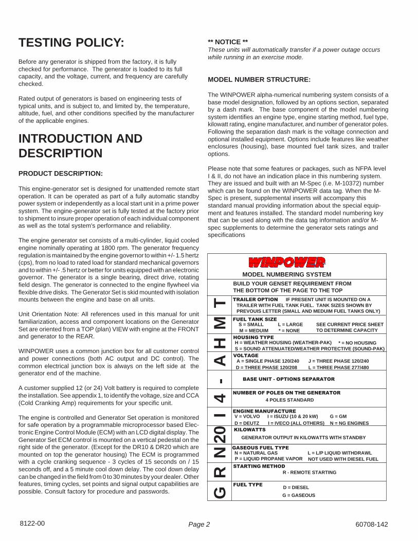
TESTING POLICY:Before any generator is shipped from the factory, it is fullychecked for performance. The generator is loaded to its fullcapacity, and the voltage, current, and frequency are carefullychecked.
Rated output of generators is based on engineering tests oftypical units, and is subject to, and limited by, the temperature,altitude, fuel, and other conditions specified by the manufacturerof the applicable engines.
INTRODUCTION ANDDESCRIPTION
PRODUCT DESCRIPTION:
This engine-generator set is designed for unattended remote startoperation. It can be operated as part of a fully automatic standbypower system or independently as a local start unit in a prime powersystem. The engine-generator set is fully tested at the factory priorto shipment to insure proper operation of each individual componentas well as the total system's performance and reliability.
The engine generator set consists of a multi-cylinder, liquid cooledengine nominally operating at 1800 rpm. The generator frequencyregulation is maintained by the engine governor to within +/- 1.5 hertz(cps), from no load to rated load for standard mechanical governorsand to within +/- .5 hertz or better for units equipped with an electronicgovernor. The generator is a single bearing, direct drive, rotatingfield design. The generator is connected to the engine flywheel viaflexible drive disks. The Generator Set is skid mounted with isolationmounts between the engine and base on all units.
Unit Orientation Note: All references used in this manual for unitfamiliarization, access and component locations on the GeneratorSet are oriented from a TOP (plan) VIEW with engine at the FRONTand generator to the REAR.
WINPOWER uses a common junction box for all customer controland power connections (both AC output and DC control). Thecommon electrical junction box is always on the left side at thegenerator end of the machine.
A customer supplied 12 (or 24) Volt battery is required to completethe installation. See appendix 1, to identify the voltage, size and CCA(Cold Cranking Amp) requirements for your specific unit.
The engine is controlled and Generator Set operation is monitoredfor safe operation by a programmable microprocessor based Elec-tronic Engine Control Module (ECM) with an LCD digital display. TheGenerator Set ECM control is mounted on a vertical pedestal on theright side of the generator. (Except for the DR10 & DR20 which aremounted on top the generator housing) The ECM is programmedwith a cycle cranking sequence - 3 cycles of 15 seconds on / 15seconds off, and a 5 minute cool down delay. The cool down delaycan be changed in the field from 0 to 30 minutes by your dealer. Otherfeatures, timing cycles, set points and signal output capabilities arepossible. Consult factory for procedure and passwords.
** NOTICE **These units will automatically transfer if a power outage occurswhile running in an exercise mode.
MODEL NUMBER STRUCTURE:
The WINPOWER alpha-numerical numbering system consists of abase model designation, followed by an options section, separatedby a dash mark. The base component of the model numberingsystem identifies an engine type, engine starting method, fuel type,kilowatt rating, engine manufacturer, and number of generator poles.Following the separation dash mark is the voltage connection andoptional installed equipment. Options include features like weatherenclosures (housing), base mounted fuel tank sizes, and traileroptions.
Please note that some features or packages, such as NFPA levelI & II, do not have an indication place in this numbering system.They are issued and built with an M-Spec (i.e. M-10372) numberwhich can be found on the WINPOWER data tag. When the M-Spec is present, supplemental inserts will accompany thisstandard manual providing information about the special equip-ment and features installed. The standard model numbering keythat can be used along with the data tag information and/or M-spec supplements to determine the generator sets ratings andspecifications

60708-142 Page 3 8122-00
The rated power of each engine-generator is limited by thetemperature, altitude and all other ambient conditions specifiedby the engine manufacturer. Engine power will decrease 3-1/2%for each 1000 ft. above sea level, and will decrease an additional1% for each 10 degrees Fahrenheit above 60 degrees Fahren-heit. Units should not be operated in ambient temperature greaterthan 125 degrees Fahrenheit.
GENERATOR:
WINPOWER Generators Sets use totally brushless, AVR (Auto-Voltage Regulator) controlled broad-range generator ends. Thegenerator converts rotational mechanical energy into electricalenergy. Standard WINPOWER units are equipped with genera-tors manufactured by Stamford/Newage. Each generator ‘end’has its own data tag. The unique serial number is stamped on thedata plate and into the upper section of the mounting adapter ofthe generator frame. The data label is affixed to the main frameof the generator on the lower left side, similar to the sampleshown.
ENGINE CONTROL PANEL LAYOUT
SPECIFICATIONSGENERATOR SET:
Every WINPOWER Generator Set has its own unique identity dataplate. This data plate identifies the complete unit model number,the system serial number and has links to the individual compo-nents that form the generator set in our factory records. Several ofthe major components also have their own individual identity platesproviding additional information to document build data for warrantyand replacement parts.
Be sure to have the main WINPOWER unit data plate informationrecorded inside the front cover of this manual for future referenceand for identification whenever requesting field or factory technicalassistance. Sample data plate is shown for reference. Primary fieldsneeded for assistance are complete model number, serial numberand especially the M-Spec number. The M-Spec number (if pro-vided) is recorded in the ‘TYPE NO.’ block on the Lower Right of theplate. See the appendixs in the back of this manual for individualunits specifications and wiring diagram references.
ENGINE:
Each engine has a nameplate on it that gives the specific enginemodel number, build specification and the serial number for theengine. See the technical data pages in the back of this manualfor individual engine specifications, fuel consumptions and wiringdiagram references.
This manual covers specific operation of the combined enginegenerator set. Refer to engine operating and maintenanceinstructions for specific instruction on the care and maintenanceof the engine. Oil and fuel requirements along with maintenanceschedules and engine warranty information are provided by theindividual engine manufactures.
** CAUTION **
EQUIPMENT DAMAGE - Be sure to check the engine oil levelfrequently as specified in the engine manual.
The engine manufacturer has established an excellent worldwideengine service organization; engine service is available from anearby authorized dealer or distributor; check the Yellow Pagesof the telephone directory under “engines,” or ask the dealer fromwhom you purchased the power plant.
Typical Winpower Nameplate

Page 48122-00 60708-142
A - DGC-2020 Digital Gen-Set Control. See Explanationbelow.
B - DC Control Circuit Fuse. The 10 amp DC Circuit Fuseprotects the 12 volt circuits and engine wiring harness againstfaults in wiring or control equipment. The fuse also prevents adischarge of the battery due to a circuit fault. (ReplacementAGC-10A-250V)
C - DGC-2020 Fuse. This 3 amp DC fuse protects the DGC-2020 printed circuit board. (Replacement AGC-3A-250V)
D - Emergency Stop Switch - When depressed this switch willdisconnect all the 12 volt power to the DGC-2020 shutting theengine down. The lamp in the emergency stop switch will lightup when the switch is depressed showing that the power to thepanel has been disconnected.
E - Voltage Adjustment Rheostat. This 2 watt 1k ohmrheostat is used to fine tune your output voltage from thegenerator. If for some reason the voltage should get way out ofrange and you can not get it back with the adjustment range onthe rheostat, there is a course voltage adjustment pot on thevoltage regulator
ENGINE CONTROL MODULE (DGC-2020)
Note: A CD was shipped with this unit to support the DGC-2020. The CD contains the complete operators manual andthe software to reprogram the DGC-2020 if the need shouldever arise. Please store it in a safe place.
The DGC-2020 Digital Generator Set Controller providesintegrated engine-generator set control, protection, andmetering in a single package. Microprocessor based technol-ogy allows for exact measurement, set point adjustment, andtiming functions. Front panel controls and indicators enable
quick and simple DGC-2020 operation. Basler Electric communica-tion software (BESTCOMSPlus) allows units to be easily custom-ized for each application. A wide temperature-range liquid crystaldisplay (LCD) with backlighting can be viewed under a variety ofambient light and temperature conditions.
FEATURESDGC-2020 Digital Generator Set Controllers have the followingfeatures:• Local and Remote Generator Control• Engine and Generator Protection• Programmable Analog Engine Senders• Programmable Logic• Automatic Transfer Switch Control (Mains Failure)• Integrated RS485 interface• Auto Synchronizing
FUNCTIONSDGC-2020 Digital Generator Set Controllers perform the followingfunctions:
Generator Protection and Metering
Generator protection guards against over voltage, under voltage,under frequency, and over frequency. Over current and phaseimbalance protection is available as an option at the time ofmanufacture. Each generator protection function has an adjustablepickup and time delay setting. Metered generator parametersinclude voltage, current, real power (watts), apparent power (VA),and power factor (PF).
Engine Protection and Metering
Engine protection features include oil pressure and coolant tem-perature monitoring, over crank protection, ECU specific protectionelements, and diagnostic reporting.
ENGINECONTROLMODULEDGC-2020
60708-142 Page 5 8122-00
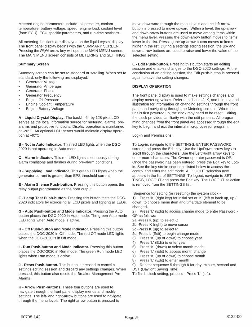
move downward through the menu levels and the left-arrowbutton is pressed to move upward. Within a level, the up-arrowand down-arrow buttons are used to move among items withinthe menu level. Pressing the down-arrow button moves to itemslower in the list. Pressing the up-arrow button moves to itemshigher in the list. During a settings editing session, the up- anddown-arrow buttons are used to raise and lower the value of theselected setting.
L - Edit Push-button. Pressing this button starts an editingsession and enables changes to the DGC-2020 settings. At theconclusion of an editing session, the Edit push-button is pressedagain to save the setting changes.
DISPLAY OPERATION
The front panel display is used to make settings changes anddisplay metering values. Refer to call-outs J, K, and L in text andillustration for information on changing settings through the frontpanel and navigating through the Metering screens. When theunit is first powered up, the clock may need to be reset. Editingthe clock provides familiarity with the edit process. All program-ming changes from the front panel are accessed through the editkey to begin and exit the internal microprocessor program.
Log-in and Permissions
To Log-in, navigate to the SETTINGS, ENTER PASSWORDscreen and press the Edit key. Use the Up/Down arrow keys toscroll through the characters. Use the Left/Right arrow keys toenter more characters. The Owner operator password is OP.Once the password has been entered, press the Edit key to Log-in. See the key stroke sequence listed below to access thecontrol and enter the edit mode. A LOGOUT selection nowappears in the list of SETTINGS. To logout, navigate to SET-TINGS, LOGOUT and press the Edit key. The LOGOUT selectionis removed from the SETTINGS list.
Sequence for setting (or resetting) the system clock -1) Press ‘K’ (right key) for initial set or ‘K’ (left to back up, up /down) to choose menu item and time/date element to bechanged.2) Press ‘L’ (Edit) to access change mode to enter Password -OP as follows:2a -Press K (up) to select O2b -Press K (right) to move cursor2c -Press K (up) to select P2d -Press L (Edit) to begin change mode3) Press ‘K’ (up or down) to choose year4) Press ‘L’ (Edit) to enter year5) Press ‘K’ (down) to select month mode6) Press ‘L’ (Edit) to access month change7) Press ‘K’ (up or down) to choose month8) Press ‘L’ (Edit) to enter month9) Repeat sequence 5 through 8 for day, minute, second andDST (Daylight Saving Time).To finish clock setting, process - Press ‘K’ (left).
Metered engine parameters include oil pressure, coolanttemperature, battery voltage, speed, engine load, coolant level(from ECU), ECU specific parameters, and run-time statistics.
All metering functions are displayed on the liquid crystal display.The front panel display begins with the SUMMARY SCREEN.Pressing the Right arrow key will open the MAIN MENU screen.The MAIN MENU screen consists of METERING and SETTINGS
Summary Screen
Summary screen can be set to standard or scrolling. When set tostandard, only the following are displayed:• Generator Voltage• Generator Amperage• Generator Phase• Generator Frequency• Engine Oil Pressure• Engine Coolant Temperature• Engine Battery Voltage
A - Liquid Crystal Display. The backlit, 64 by 128 pixel LCDserves as the local information source for metering, alarms, pre-alarms and protective functions. Display operation is maintainedat -20°C. An optional LCD heater would maintain display opera-tion at -40°C.
B - Not in Auto Indicator. This red LED lights when the DGC-2020 is not operating in Auto mode.
C - Alarm Indicator. This red LED lights continuously duringalarm conditions and flashes during pre-alarm conditions.
D - Supplying Load Indicator. This green LED lights when thegenerator current is greater than EPS threshold current.
E - Alarm Silence Push-button. Pressing this button opens therelay output programmed as the horn output.
F - Lamp Test Push-button. Pressing this button tests the DGC-2020 indicators by exercising all LCD pixels and lighting all LEDs.
G - Auto Push-button and Mode Indicator. Pressing the Autobutton places the DGC-2020 in Auto mode. The green Auto modeLED lights when Auto mode is active.
H - Off Push-button and Mode Indicator. Pressing this buttonplaces the DGC-2020 in Off mode. The red Off mode LED lightswhen the DGC-2020 is in Off mode.
I - Run Push-button and Mode Indicator. Pressing this buttonplaces the DGC-2020 in Run mode. The green Run mode LEDlights when Run mode is active.
J - Reset Push-button. This button is pressed to cancel asettings editing session and discard any settings changes. Whenpressed, this button also resets the Breaker Management Pre-Alarms
K - Arrow Push-buttons. These four buttons are used tonavigate through the front panel display menus and modifysettings. The left- and right-arrow buttons are used to navigatethrough the menu levels. The right arrow button is pressed to

Page 68122-00 60708-142
The microprocessor is still in the General Settings Edit mode.Pressing ‘K’ (left) a second time exits the Edit mode and allowsfull access to the View Only mode for all control settings andcurrent status. Any items to be changed are accessed bypressing ‘K’ (up/down/right or left) to select, ‘L’ (Edit) to changeand ‘K’ (left) to exit.
Communication
Standard DGC-2020 communication features include a standardUSB port and SAE J1939 interface. Optional communicationfeatures include a dial-out modem and RS-485 communication port.The USB communication port can be used with BESTCOMSPlussoftware to quickly configure a DGC-2020 with the desired settingsor retrieve metering values and event log records. The CANBusinterface provides high-speed communication between the DGC-2020 and the engine control unit (ECU) on an electronically con-trolled engine. This interface provides access to oil pressure, cool-ant temperature, and engine speed data by reading these param-eters directly from the ECU. When available, engine diagnostic datacan also be accessed. The CANBus interface supports the follow-ing protocols:
• SAE J1939 Protocol - Oil pressure, coolant temperature, andengine speed data are received from the ECU. In addition, DTCs(Diagnostic Trouble Codes) help diagnose any engine or relatedfailures. The engine DTCs are displayed on the front panel of theDGC-2020 and may be obtained using BESTCOMSPlus software.
• MTU/MDEC Protocol - A DGC-2020 connected to a generatorSet equipped with an MTU MDEC receives Oil pressure, coolanttemperature, and engine speed data from the engine controller, alongwith various alarms and pre-alarms that are MDEC specific. In ad-dition, the DGC-2020 tracks and displays the active fault codes is-sued by the MDEC ECU.
Optional - Dial-Out Modem One of two optional, dial-out modems(a US version or international version) enables remote control,monitoring, and setting of the DGC-2020. When an alarm or pre-alarm condition occurs, the DGC-2020 can dial up to four telephonenumbers, in sequence, until an answer is received and the condi-tion is annunciated.
Optional - RS-485 Port The RS-485 communication port uses theModbus communication protocol and enables remote control andmonitoring of the DGC-2020 over a polled network
.RECEIVING THE GENERATORThe generator set will generally be shipped by a commercial ‘com-mon freight carrier’. Large and bulky units are often shipped on adedicated or specially contracted ‘Flat-Bed’ truck. The means ofshipment is determined in consultation between the WINPOWERSales and Shipping staff and the customer. Routing is determinedby the bulk, size, and a means available to unload the generator atthe receiving end. WINPOWER recommends units that are shippedby common carrier be delivered to a commercial dock to allow theGenerator Set to be unloaded in a safe, efficient manner and tominimize handling damage to the unit.
Locate the packing slip on the side of the crate or request it fromthe truck driver. When receiving the unit take special care in exam-
ining the unit for damage during shipment. Avoid signing for theequipment until a full visual assessment and inventory have beenmade. Verify that you have received the right equipment and theproper amount by matching up the equipment to the packing list.Larger units may ship with the fuel tank and muffler removed. Verifythat those components are undamaged and removed from the truckprior to their release.
The keys for doors of the enclosed generators sets are typicallyattached to lifting eye on the base of the machine. These keys arematched to all the doors on the generator set housing.
UNPACKING INSTRUCTIONS:
When unpacking the generator set, be sure to inspect it carefully forfreight loss or damage. If loss or damage is noted at the time ofdelivery, require that the person making the delivery make note ofthe loss or damage on the freight bill, or affix his signature under theconsignee’s memo of the loss or damage. Contact the carrier forclaim procedures.
When loss or damage is noted after delivery, segregate the dam-aged material, and contact the carrier for claim procedures.
“Concealed Damage” is understood to mean damage to the con-tents of a package which is not in evidence at the time of delivery bythe carrier, but which is discovered later. The carrier or carriers areresponsible for merchandise lost or damaged in transit. The title togoods rests with the consignee when generators are shipped fobfactory, and only the consignee can legally file a claim.
***** CAUTION ****
EQUIPMENT DAMAGE - These units are shipped with oil,and a 50/50 mix of coolant. Be sure to check all fluidlevels before operating. See engine manufacturer’sinstruction manual for recommended oil requirementsbefore initial starting.
UNPACKING:(Not recommended until the unit is on-site)
1. Carefully remove the crate.
2. After inspecting the engine-generator for external physicaldamage, locate and check the following items packed withthe unit.
a. Owner’s operators manual.b. Engine manufacturer’s instruction manual.c. Battery hold-down brackets & hardware.d. Unit components or accessory items shipped loose
for on-site installation.e. Optional accessories (i.e. remote annunciator)
3. Remove main frame hold down bolts.
4. Unit can now be lifted from shipping rails.

60708-142 Page 7 8122-00
LIFTING THE GENERATOR SET
NOTICE - Personal Injury
To prevent injury to persons or equipment, observe the follow-ing guidelines when lifting the generator:
Due to the different designs, configurations, options, weights, siteconditions, and available material handling equipment, specific lift-ing instructions are not provided for each individual generator setmodel. General guidelines provided are applicable to the entirestandby generator line. It is the responsibility of the installing partyto follow the lifting equipment’s operators manual to prevent injuryto personnel and damage to the generator. Smaller Generator Setsmay not require use of overhead lifting equipment and may be placedon the pad with basic material handling equipment, i.e. a forklift.
CAUTION: - Do not attempt to lift the generator set by the meansof the lifting eyes on the engine or generator end.
These lifting points are only for use during the manufacturing pro-cess and are designed for lifting of the individual Generator Setcomponent.
WINPOWER has designed all of its Generators Sets to be lifted atthe corners with an appropriate lifting rig. The lifting points arelocated on the side rails of the generator base or on the optionalbase mounted fuel tank of a Diesel Generator Set.
The generator set can be lifted with properly rated chains or cablesalong with the use of spreader bars. The spreader bars should belong enough so that the lift cables or chains do not come into con-tact with the generator set. Use of commercially available liftingfixtures may also be used. Always be sure that the equipment isproperly rated for the weight of the generator. Failure to do so cancause damage to the generator, injury to personnel or even death.
The generator set and fuel tank may or may not be shipped as acomplete unit. If the fuel tank is shipped separate from the genera-tor, place the tank on the cement pad first, and then place the gen-erator on top of the fuel tank.
******************** WARNING ****
***************NEVER - attempt to lift the fuel tank while filled with fuel. Slosh-ing of the fuel can cause a shift in the balance of the fuel tank,making for a DANGEROUS, unbalanced lifting load. If the gen-erator was shipped on the fuel tank, use the lifting points lo-cated on the fuel tank to move the entire Generator Set intoplace. DO NOT place fuel in the tank prior to lifting.
Depending on generator set size and configuration, the exhaustsystem may ‘ship loose’ with the generator set for installation onsite. The muffler and its attaching brackets must be mounted ontop of the generator housing prior to operating the enginegenerator set.
INSTALLATION

Page 88122-00 60708-142
******************** WARNING ****
***************PERSONAL INJURY - Before proceeding with the installation,be sure the DGC-2020 is in the "stop" position. Beforeproceeding with the installation, be sure the Generator MLCB(Main Line Circuit Breaker) is in the ‘OFF’ position and theunit starting battery is disconnected.
GENERAL INFORMATION
These engine/generator sets are generally supplied as weatherenclosed packages for quick installation on an outdoor concretepad. They are also available as open skid mounted units for indoorinstallation in a building or protective enclosure supplied by theinstaller. The factory weather enclosures are available as standardor acoustical housing intended for outdoor installation only. Factoryweather enclosed units are not intended to be used indoors andno support is available to assist in re-engineering finishedpackaged units.
All versions must be bolted to a solid base for proper operation. Aproperly designed concrete pad is necessary for stationary opera-tion. A substantial DOT certified trailer is required for mobile appli-cations. Consult a qualified, licensed electrician or contractor toinstall and wire this Generator Set. The installation must complywith all national, state, and local codes.
Before beginning the installation process, recheck the voltage,phase and amperage rating of the Generator Set and ATS (Auto-matic Transfer Switch). Be certain they can handle the intended loadand are compatible with the entrance voltage, phase and currentratings. Plans for installation should be prepared with properattention to mechanical and electrical engineering detail to assure asatisfactory system installation.
The information in this manual is offered only as a guide to finalizingyour installation plans.
NOTICE
For full service switching of the entire load, the ATS must be ‘SE’(Service Entrance) rated or must have a properly rated fusibledisconnect installed before the ATS to protect the contacts..ENGINE GENERATOR SET MOUNTING
The unit’s main frame must be bolted solidly to a 4 to 6 inch thickcement pad. The engine-generator is mounted on a sub-framewhich is attached with special shock mounts to the main frame.This allows the engine-generator free movement without affectingthe control panel which is mounted on the main frame.
Do not shock mount the main frame. Engine vibration will betransmitted to the control panel causing erroneous start/stopcycles and premature control failure.
The unit should be mounted to allow for ample working roomaround it. A general rule to follow is five (5) feet of clearance onall sides. (Code NFPA 37)
FUEL INSTALLATION
The fuel supply should be as close to the engine as possible. Thiswill reduce the installation cost of fuel runs and minimize line losses.The diesel fuel supply should be no more than 3 feet below the fuelinlet on the pump. If your fuel supply is lower than three feet you mayhave to install an additional lift pump to bring the fuel up to themechanical fuel pump on the engine.
The information in this manual is offered to assist you in providing theproper fuel for your engine. However, this information is only pro-vided to inform you of the engine’s requirements and assist inmaking you aware of the decisions you must make. In no caseshould the instructions or information provided be interpreted toconflict with any local, state or national codes. If in doubt, alwaysconsult your local fire marshal or fuel supplier.
INSTALLING THE FUEL LINE
Engine generator sets are properly adjusted before they leave thefactory. Connecting a fuel supply with adequate supply volume iscritical to reliable operation. Diesel units with optional base mountedfuel tanks are pre-plumbed to the mechanical fuel pump on theengine.
Open skid mounted Diesel units are often supplied with capped inletand return lines. The use of a suitable customer supplied flexible fuelline is essential between the engine and fuel supply to provide avibration break between your fuel supply and the engine.
******************** WARNING ****
***************
FIRE DANGER - Connecting rigid fuel line (i.e. steel or copperline) directly to the inlet fuel filter or fuel pump may cause thefuel line to crack during operation creating a serious firehazard.
LUBRICATION
Before starting the engine, check the oil level in the crankcase. Ifit is low, refill to the full mark with the proper weight/grade of oil asrecommended by the engine manufacturer’s maintenanceinstructions. The necessity of using the correct oil, and keepingthe crankcase full cannot be over emphasized. Failure to use theproper oil and keep the crankcase properly filled will causeexcessive engine wear and shorten its useful life.
COOLANT
Before starting the engine, check the coolant level in the radiator.If it is low, refill as specified in the engine manufacturer’s mainte-nance instructions. The radiator should be filled to about 1 inchbelow the filler neck. For additional information on engine coolantrequirements see engine manufacturer’s maintenance instruc-tions.

60708-142 Page 9 8122-00
INSTALLING THE BATTERY**** CAUTION ****
In the following battery installation procedure, check to besure the DGC-2020 is in the “stop” position. This should beyour last step before initial start-up.
A customer supplied twelve-volt battery is required to completethe installation; 24 volt systems require 2 batteries. Installation ofthe highest CCA rated battery, within the correct BCI group, willincrease cold weather starting performance. Gel batteries shouldnot be used with the battery tender installed in the generatorenclosure.
See the specification listing in appendix 1 for the correct batterysize and minimum CCA rating for the different models.
Installation and servicing of batteries must be performed orsupervised only by personnel knowledgeable of batteries and therequired precautions. Keep unauthorized personnel away frombatteries.
When installing or replacing batteries, use the proper group/sizestarting battery. The battery should be a Maintenance Free leadacid design. Deep cycle batteries will not work for this applica-tion.
CAUTION – PERSONAL DANGER
CAUTION - NEVER dispose of a battery in a fire. The battery iscapable of exploding.
CAUTION -DO NOT open or mutilate the battery. Releasedelectrolyte is known to be harmful to the skin and eyes and to bevery toxic.
These engine generator sets are all NEGATIVE ground. Be verycareful not to connect the battery in reverse polarity, as this mayshort circuit the battery charging system on the engine.
CAUTION – A battery presents a risk of electrical shock and highshort circuit current. The following precautions must be observedwhen working with batteries:
1. Remove watches, rings and other metal objects.2. Use tools with insulated handles.3. Check both the battery cable ends and the battery posts to besure they are free of corrosion.3. Always connect the battery positive cable first and thenconnect the battery negative cable. When removing the batterycables from the battery reverse the procedure, disconnect thenegative cable first and then the positive cable.4. Be sure all connections are tight and coat the terminals andcable ends with dialectic grease.
WARNING – The electrolyte is a diluted sulfuric acid that isharmful to the skin and eyes. It is electrically conductive andcorrosive. The following precautions must always be taken:
* Always wear full eye protection and protective clothing* Where electrolyte contacts the skin, wash off immediatelywith water* If electrolyte contacts the eyes, flush thoroughly and immedi-ately with water and seek immediate medical attention* Spilled electrolyte is to be washed down with an acid neutral-izing agent. A common practice is to use a solution of one poundof bicarbonate of soda (baking soda) to one gallon of water. Thebicarbonate of soda solution is to be added until the evidence ofreaction, foaming, has ceased. The resulting liquid is to beflushed with water and the area dried.
DANGER – Explosive Fire Risk
* Never smoke when near batteries* Do not cause a flame or spark in the battery area* Always discharge static electricity from your body beforetouching batteries by first touching a grounded metal surface
SERVICING BATTERIES
Batteries used on these units may, over time, lose water. This isespecially true if you are using a trickle charger to maintain yourbattery. When refilling the battery with water use only distilledwater. Tap water will shorten the service life of the battery.
Never fill the battery above the fill line. Over filling above theupper level line may cause the electrolyte to overflow, resulting incorrosion to the engine or nearby parts. Immediately wash offany spilled electrolyte following the procedure above.
NOTE: Always make sure that a new battery is fully chargedbefore installing it on a generator set. Failure to do so cancause damage to the engine control module in the generatorset.
All connections must be clean and tight. Check the electrolyte(fluid) in the battery periodically to be sure it is above the plates.Never allow the battery to remain in a discharged condition.
CONNECTING THE BATTERY CHARGER &BLOCKHEATER
A two-stage battery tender is provided for all standby generators.These battery chargers can vary depending on what model youhave purchased and what the original specifications call for. Forunit operating at 12 volts D.C. the standard charger is a batterytender that charges at a rate of 750 mA until the battery is fullycharged and then automatically switches to a 13.2 VDC floatcharger. The charger has an indicator light on it, red indicates itis charging, and green indicates it is in the storage mode (floatcharge). This charger is mounted on the left hand side of the ACconnection cabinet.
All 24 volt battery chargers and option 12 volt chargers will haveeither a cord on them that you can plug into the receptacle on theside of the connection box or depending on size they may requirehard wiring in the terminal block in the bottom of the connectionbox.

Page 108122-00 60708-142
** NOTICE **The trickle charger is not intended to recharge a batterywhich has become completely discharged. It is designed toproduce just enough current to maintain a fully chargedbattery.
The battery tender receptacle is to be powered by a GFCI circuitand installed in accordance with the United States NationalElectric Code. It is suggested that this circuit be fused for 20 -30amps, depending on blockheater requirements. Then both thebattery charger and the block heater can be connected to thesame circuit. A 120 volt duplex receptacle is mounted on thegenerator along the side circuit breaker panel, for a 20 ampcircuit and terminal blocks are provided for heavier circuits.
The engine blockheater installed on this unit should also beplugged in this receptacle. The block heater is thermostaticallycontrolled and when plugged in will maintain the engine coolanttemperature between 100 and 120 degrees F.
MOUNTING THE AUTOMATICTRANSFER SWITCH (A.T.S.) ****************** WARNING ***** *************FIRE HAZARD - All wiring must be done by a licensedelectrician, and must conform to the National Electrical Codeand comply with all state and local codes and regulations.Check with the local authorities before proceeding!
INSTALLATION NOTES
Because of the many different types of service, feeder, anddistribution equipment, no specific wiring instructions can beprovided. It is recommended that only copper wire be used. Inall cases it is essential that while the load is connected to thegenerator, there can be absolutely no feedback from the genera-tor to the power line or the power line to the generator. Whenproperly installed, the normal A.T.S. Control and safety systemswill eliminate all paths for feedback.
To wire the automatic transfer switch into the existing wiring, firstdetermine which circuits will be on the emergency load circuit. Ifthe entire load is to be transferred, the transfer switch can bewired in directly after the watt-hour meter and the service en-trance, providing the service entrance ampere rating is within thetransfer switch’s rated capability.
If only specific circuits are to be powered under emergency powerfailure conditions, an additional distribution panel designated“emergency distribution panel” must be installed.
All selected emergency circuits are removed from main distribu-tion panels and installed in the emergency distribution panel. TheA.T.S. is then installed between the main panel and the emer-gency distribution panel. Suggested circuits: freezer, refrigerator,furnace, emergency lights, sump pump, emergency outlet circuits,etc. Total running load must not exceed generator rating.
A.C. ELECTRICALCONNECTIONSNOTICE - CLASS 1 WIRING METHODS ARE TO BE USED FOR
ALL FIELD WIRING CONNECTIONS TO TERMINALS OF ACLASS 2 CIRCUIT
Note: This symbol always indicates ground whereshown.
All wiring must be completed in accordance with the NationElectric Code as well as any state or local codes.
You must pay particular attention to wire size requirement for theamperage of service you are dealing with. Appendix "2" providesyou guidance on wire sizing based on both wire type and amper-age. Wire amperage's have been derated for 40o C ambienttemperatures operation.
CUSTOMER CONNECTION BOX FORBOTH AC & DC CONNECTION10 kW THROUGH 125 kW
60708-142 Page 11 8122-00
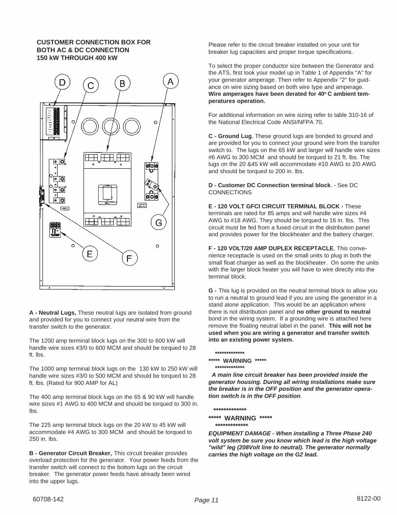
A - Neutral Lugs, These neutral lugs are isolated from groundand provided for you to connect your neutral wire from thetransfer switch to the generator.
The 1200 amp terminal block lugs on the 300 to 600 kW willhandle wire sizes #3/0 to 600 MCM and should be torqued to 28ft. lbs.
The 1000 amp terminal block lugs on the 130 kW to 250 kW willhandle wire sizes #3/0 to 500 MCM and should be torqued to 28ft. lbs. (Rated for 900 AMP for AL)
The 400 amp terminal block lugs on the 65 & 90 kW will handlewire sizes #1 AWG to 400 MCM and should be torqued to 300 in.lbs.
The 225 amp terminal block lugs on the 20 kW to 45 kW willaccommodate #4 AWG to 300 MCM and should be torqued to250 in. lbs.
B - Generator Circuit Breaker, This circuit breaker providesoverload protection for the generator. Your power feeds from thetransfer switch will connect to the bottom lugs on the circuitbreaker. The generator power feeds have already been wiredinto the upper lugs.
Please refer to the circuit breaker installed on your unit forbreaker lug capacities and proper torque specifications.
To select the proper conductor size between the Generator andthe ATS, first look your model up in Table 1 of Appendix "A" foryour generator amperage. Then refer to Appendix "2" for guid-ance on wire sizing based on both wire type and amperage.Wire amperages have been derated for 40o C ambient tem-peratures operation.
For additional information on wire sizing refer to table 310-16 ofthe National Electrical Code ANSI/NFPA 70.
C - Ground Lug, These ground lugs are bonded to ground andare provided for you to connect your ground wire from the transferswitch to. The lugs on the 65 kW and larger will handle wire sizes#6 AWG to 300 MCM and should be torqued to 21 ft. lbs. Thelugs on the 20 &45 kW will accommodate #10 AWG to 2/0 AWGand should be torqued to 200 in. lbs.
D - Customer DC Connection terminal block. - See DCCONNECTIONS
E - 120 VOLT GFCI CIRCUIT TERMINAL BLOCK - Theseterminals are rated for 85 amps and will handle wire sizes #4AWG to #18 AWG. They should be torqued to 16 in. lbs. Thiscircuit must be fed from a fused circuit in the distribution paneland provides power for the blockheater and the battery charger.
F - 120 VOLT/20 AMP DUPLEX RECEPTACLE, This conve-nience receptacle is used on the small units to plug in both thesmall float charger as well as the blockheater. On some the unitswith the larger block heater you will have to wire directly into theterminal block.
G - This lug is provided on the neutral terminal block to allow youto run a neutral to ground lead if you are using the generator in astand alone application. This would be an application wherethere is not distribution panel and no other ground to neutralbond in the wiring system. If a grounding wire is attached hereremove the floating neutral label in the panel. This will not beused when you are wiring a generator and transfer switchinto an existing power system.
****************** WARNING ***** ************* A main line circuit breaker has been provided inside thegenerator housing. During all wiring installations make surethe breaker is in the OFF position and the generator opera-tion switch is in the OFF position.
****************** WARNING ***** *************EQUIPMENT DAMAGE - When installing a Three Phase 240volt system be sure you know which lead is the high voltage"wild" leg (208Volt line to neutral). The generator normallycarries the high voltage on the G2 lead.
CUSTOMER CONNECTION BOX FORBOTH AC & DC CONNECTION150 kW THROUGH 400 kW
Page 128122-00 60708-142
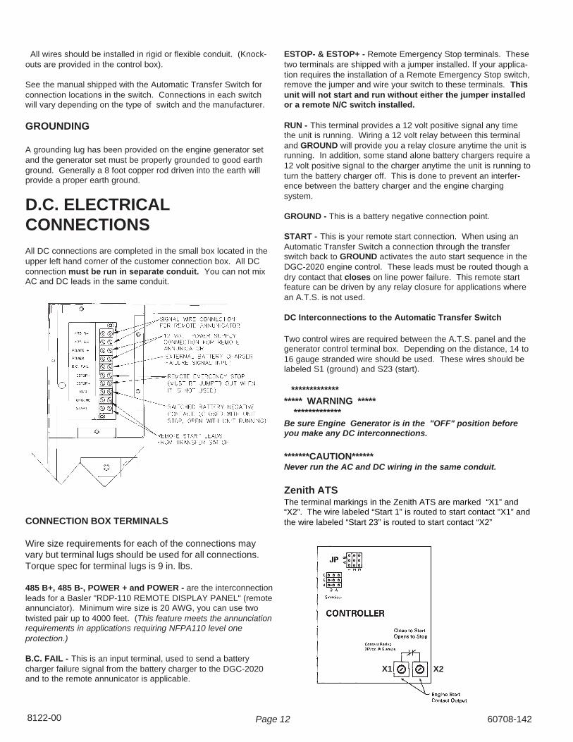
All wires should be installed in rigid or flexible conduit. (Knock-outs are provided in the control box).
See the manual shipped with the Automatic Transfer Switch forconnection locations in the switch. Connections in each switchwill vary depending on the type of switch and the manufacturer.
GROUNDING
A grounding lug has been provided on the engine generator setand the generator set must be properly grounded to good earthground. Generally a 8 foot copper rod driven into the earth willprovide a proper earth ground.
D.C. ELECTRICALCONNECTIONSAll DC connections are completed in the small box located in theupper left hand corner of the customer connection box. All DCconnection must be run in separate conduit. You can not mixAC and DC leads in the same conduit.
ESTOP- & ESTOP+ - Remote Emergency Stop terminals. Thesetwo terminals are shipped with a jumper installed. If your applica-tion requires the installation of a Remote Emergency Stop switch,remove the jumper and wire your switch to these terminals. Thisunit will not start and run without either the jumper installedor a remote N/C switch installed.
RUN - This terminal provides a 12 volt positive signal any timethe unit is running. Wiring a 12 volt relay between this terminaland GROUND will provide you a relay closure anytime the unit isrunning. In addition, some stand alone battery chargers require a12 volt positive signal to the charger anytime the unit is running toturn the battery charger off. This is done to prevent an interfer-ence between the battery charger and the engine chargingsystem.
GROUND - This is a battery negative connection point.
START - This is your remote start connection. When using anAutomatic Transfer Switch a connection through the transferswitch back to GROUND activates the auto start sequence in theDGC-2020 engine control. These leads must be routed though adry contact that closes on line power failure. This remote startfeature can be driven by any relay closure for applications wherean A.T.S. is not used.
DC Interconnections to the Automatic Transfer Switch
Two control wires are required between the A.T.S. panel and thegenerator control terminal box. Depending on the distance, 14 to16 gauge stranded wire should be used. These wires should belabeled S1 (ground) and S23 (start).
****************** WARNING ***** *************Be sure Engine Generator is in the "OFF" position beforeyou make any DC interconnections.
*******CAUTION******Never run the AC and DC wiring in the same conduit.
Zenith ATSThe terminal markings in the Zenith ATS are marked “X1” and“X2”. The wire labeled “Start 1” is routed to start contact "X1” andthe wire labeled “Start 23” is routed to start contact “X2”CONNECTION BOX TERMINALS
Wire size requirements for each of the connections mayvary but terminal lugs should be used for all connections.Torque spec for terminal lugs is 9 in. lbs.
485 B+, 485 B-, POWER + and POWER - are the interconnectionleads for a Basler "RDP-110 REMOTE DISPLAY PANEL" (remoteannunciator). Minimum wire size is 20 AWG, you can use twotwisted pair up to 4000 feet. (This feature meets the annunciationrequirements in applications requiring NFPA110 level oneprotection.)
B.C. FAIL - This is an input terminal, used to send a batterycharger failure signal from the battery charger to the DGC-2020and to the remote annunicator is applicable.
X1 X2

60708-142 Page 13 8122-00
ASCO 165 UL SWITCHYour DC connection points in the ASCO 165 ATS areterminals “4” and “5 on the interface terminal block.
ASCO 300 UL SWITCH
Your DC connection points in the ASCO 300 ATS areterminals “14” and “15”. Depending on the size of theswitch they are located in different locations.
INITIAL START UP
****************** WARNING ***** *************EQUIPMENT DAMAGE - DO NOT jump start these enginegenerator sets. Starting these units on a low battery or jumpstarting them will cause damage to the engine control module.
Use the following check list to verify correct installation beforestarting the engine:
1. Engine oil. Fill as required with proper grade/qty.2. Engine coolant. Fill as required with proper
mixture.3. Unit mounting base properly bolted down.4. Clearance for service and maintenance on all
sides.5. Proper fuel line material and size.6. All fuel line connections tight.7. Battery connections clean and tight.8. Battery fully charged.9. All AC and DC wiring installed and properly
protected.
After completing the above checklist, the engine-generatorset is ready for the initial start-up test.
PROCEDURE
Depress the “RUN” push-button on the front of the DGC. Theengine-generator will crank and start automatically. If the enginefails to start, depress the “stop” push-button and correct thetrouble before proceeding.
With the engine running smoothly check the no load voltage andfrequency on the digital display. The voltage should be 208/240/480 AC depending on which model you have and a frequency of59.5 To 60.5 hertz (Hz).
If you have the proper voltage at the generator the next step is tocheck the voltage at the generator terminals in the AutomaticTransfer Switch. The voltage between the G1 and the G3terminals should be the same as it was on the generator frontpanel. The voltage should also be checked between the hotterminals (G1 and G3) and the G-N to be certain of a balancedvoltage output and a solid neutral connection. The voltagebetween G1 and G-N should be about 120 volts AC (277 on 480units). The same approximate voltage should be found betweenterminals G3 and G-N (120 volts AC).
On three phase panels the G2 voltage level should also bechecked. ON 240 VOLT (DELTA) SYSTEMS BE SURE YOUKNOW WHERE THE HIGH VOLTAGE "WILD" LEG IS. ITMUST BE IN THE SAME LOCATION ON THE LINE SIDE AS ITIS ON THE GENERATOR SIDE. (i.e. if it's on L-2 on the line sideit must be on G-2 on the generator side.
** Notice **If for any reason during the check out procedure the voltageand frequency are not correct, depress the “OFF” push-button and correct the trouble before proceeding.
After verifying that the voltage and frequency are correct, depressthe “OFF” push-button. The unit should shut off with no timedelay. You are now ready to test the automatic start function.

Page 148122-00 60708-142
To test the Automatic Transfer Switch follow the instruction in theoperators manual you received with your transfer switch. If youget a fault light during the initial start up or prior to start up it ismost likely a false warning light. Simply reset the A.T.S. and startover.
Once you have completed testing of the ATS, be sure youALWAYS leave the system in standby mode unless servicing theunit. For standby operation, press the "AUTO" button on the frontof the engine control. The green light should light up under the"AUTO" button.
SETTING THE EXERCISER CIRCUITFor all ATS's see the instruction manual shipped with the ATS forinstruction on setting the exercise circuit in your ATS
TROUBLESHOOTING TABLESNote: Before doing any troubleshooting, check the digitaldisplay on the DGC-2020. Normally it will tell why the unit hasfailed. This will shorten your troubleshooting time and inmany cases prevent the replacement of parts that may not bedefective.
UNIT WILL NOT CRANK WHEN THE POWER FAILS.
1. Digital Genset Controller not in "AUTO"2. Transfer control switch not in "AUTOMATIC"
position.3. Incorrect wiring between transfer switch and
generator.4. Defective control relay in the transfer
switch.5. Fuse (s) blown in the Digital Genset Controller.6. Defective Digital Genset Controller7. Loose or dirty battery terminals.8. Defective starter.9. Defective start solenoid.
10. Dead Battery
ENGINE WILL NOT CRANK WITH GENERATORRUN PUSH-BUTTON DEPRESSED.
1. Battery dead.2. Blown DC fuses on the Digital Genset Controller
tripped.3. Defective Digital Genset Controller.4. Loose or dirty battery terminals.5. Defective "Run/Auto" switch on generator.6. Defective starter.7. Defective start solenoid.8. Locked up engine genset.
ENGINE CRANKS BUT WILL NOT START
1. Improper fuel delivery to the unit.2. Fuel supply shut off.3. Fuel tank empty.4. Air in the injection system.5. Engine fuel rack has not opened.6. Defective CANBus on the engine
ENGINE STARTS AND THEN STOPS AND ALARMLIGHT COMES ON
1. Engine is low on oil.2. Engine has high water temperature.3. Engine has overspeed.4. Engine has gone into overcrank.5. No output from AC generator.6. Loss of speed signal.7. Loss of run signal.
ENGINE WILL NOT COME UP TO SPEED AFTER ITSTARTS
1. Insufficient fuel volume getting to the unit.a. Too small of fuel line.b. Fuel racks not opened properly
2. Governor is defective.3. AC short in generator components.
ATS PANEL WILL NOT TRANSFER TO EMERGENCYSUPPLY (GENERATOR)
1. No AC generator output from generator.2. Defective ATS control board. See applicable
transfer switch manual .3. Circuit breaker between generator and transfer
switch is either open or defective.
ATS PANEL WILL NOT RETRANSFER TO NORMALPOWER
1. Proper normal line power not available at lineterminals in ATS panel.
2. Defective ATS control board. See applicabletransfer switch manual .
NO AC OUTPUT FROM GENERATOR
1. Defective diode.2. Defective voltage regulator.3. Defective rotor.4. Defective stator.5. Defective exciter rotor.6. Defective exciter stator.7. AC short in the output leads.8. Defective field circuit breaker.9. Wiring error

60708-142 Page 15 8122-00
APPENDIXUNIT SPECIFICATIONS PAGE 16
ENGINE MODEL NUMBER PAGE 16BATTERY REQUIREMENTS PAGE 16FULL LOAD FUEL REQUIREMENTS PAGE 16
WIRE SIZING TABLE PAGE 17WIRING DIAGRAM CROSS REFERENCE
BY MODEL NUMBER PAGE 18GENERATOR AC CONNECTION DIAGRAM
120/240 VOLT SINGLE PHASE PAGE 19120/240 VOLT THREE PHASE PAGE 19120/208 VOLT THREE PHASE PAGE 20277/480 VOLT THREE PHASE PAGE 20VOLTAGE REGULATOR CONNECTION PAGE 15
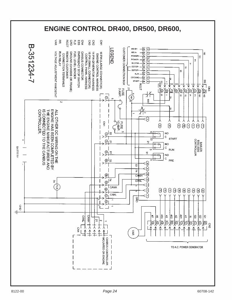
GENERATOR CONTROL PANEL WIRINGDR20 PAGE 21DR45, DR65, DR90, DR130, DR200 PAGE 22DR175, DR250, DR300, DR350 PAGE 23DR400, DR500, DR600 PAGE 24
ENGINE WIRING HARNESSDR20 PAGE 25DR45, DR65, DR90, DR130, DR200 PAGE 26DR175, DR250, DR300, DR350 PAGE 27DR400, DR500, DR600 PAGE 28
GENERATOR CROSS REFERENCE PAGE 29WARRANTY STATEMENT PAGE 30
VOLTAGE REGULATOR WIRINGTHREE PHASE AND SINGLE PHASE
60708-142Page 168122-00
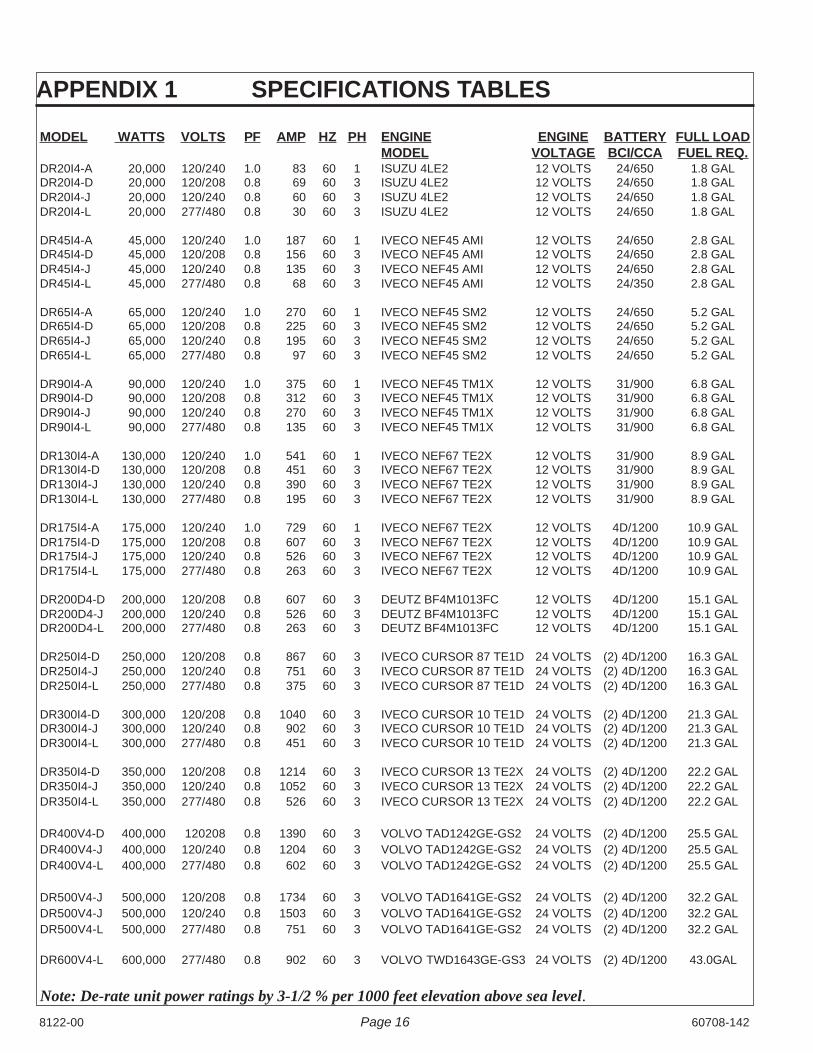
MODEL WATTS VOLTS PF AMP HZ PH ENGINE ENGINE BATTERY FULL LOADMODEL VOLTAGE BCI/CCA FUEL REQ.
DR20I4-A 20,000 120/240 1.0 83 60 1 ISUZU 4LE2 12 VOLTS 24/650 1.8 GALDR20I4-D 20,000 120/208 0.8 69 60 3 ISUZU 4LE2 12 VOLTS 24/650 1.8 GALDR20I4-J 20,000 120/240 0.8 60 60 3 ISUZU 4LE2 12 VOLTS 24/650 1.8 GALDR20I4-L 20,000 277/480 0.8 30 60 3 ISUZU 4LE2 12 VOLTS 24/650 1.8 GAL
DR45I4-A 45,000 120/240 1.0 187 60 1 IVECO NEF45 AMI 12 VOLTS 24/650 2.8 GALDR45I4-D 45,000 120/208 0.8 156 60 3 IVECO NEF45 AMI 12 VOLTS 24/650 2.8 GALDR45I4-J 45,000 120/240 0.8 135 60 3 IVECO NEF45 AMI 12 VOLTS 24/650 2.8 GALDR45I4-L 45,000 277/480 0.8 68 60 3 IVECO NEF45 AMI 12 VOLTS 24/350 2.8 GAL
DR65I4-A 65,000 120/240 1.0 270 60 1 IVECO NEF45 SM2 12 VOLTS 24/650 5.2 GALDR65I4-D 65,000 120/208 0.8 225 60 3 IVECO NEF45 SM2 12 VOLTS 24/650 5.2 GALDR65I4-J 65,000 120/240 0.8 195 60 3 IVECO NEF45 SM2 12 VOLTS 24/650 5.2 GALDR65I4-L 65,000 277/480 0.8 97 60 3 IVECO NEF45 SM2 12 VOLTS 24/650 5.2 GAL
DR90I4-A 90,000 120/240 1.0 375 60 1 IVECO NEF45 TM1X 12 VOLTS 31/900 6.8 GALDR90I4-D 90,000 120/208 0.8 312 60 3 IVECO NEF45 TM1X 12 VOLTS 31/900 6.8 GALDR90I4-J 90,000 120/240 0.8 270 60 3 IVECO NEF45 TM1X 12 VOLTS 31/900 6.8 GALDR90I4-L 90,000 277/480 0.8 135 60 3 IVECO NEF45 TM1X 12 VOLTS 31/900 6.8 GAL
DR130I4-A 130,000 120/240 1.0 541 60 1 IVECO NEF67 TE2X 12 VOLTS 31/900 8.9 GALDR130I4-D 130,000 120/208 0.8 451 60 3 IVECO NEF67 TE2X 12 VOLTS 31/900 8.9 GALDR130I4-J 130,000 120/240 0.8 390 60 3 IVECO NEF67 TE2X 12 VOLTS 31/900 8.9 GALDR130I4-L 130,000 277/480 0.8 195 60 3 IVECO NEF67 TE2X 12 VOLTS 31/900 8.9 GAL
DR175I4-A 175,000 120/240 1.0 729 60 1 IVECO NEF67 TE2X 12 VOLTS 4D/1200 10.9 GALDR175I4-D 175,000 120/208 0.8 607 60 3 IVECO NEF67 TE2X 12 VOLTS 4D/1200 10.9 GALDR175I4-J 175,000 120/240 0.8 526 60 3 IVECO NEF67 TE2X 12 VOLTS 4D/1200 10.9 GALDR175I4-L 175,000 277/480 0.8 263 60 3 IVECO NEF67 TE2X 12 VOLTS 4D/1200 10.9 GAL
DR200D4-D 200,000 120/208 0.8 607 60 3 DEUTZ BF4M1013FC 12 VOLTS 4D/1200 15.1 GALDR200D4-J 200,000 120/240 0.8 526 60 3 DEUTZ BF4M1013FC 12 VOLTS 4D/1200 15.1 GALDR200D4-L 200,000 277/480 0.8 263 60 3 DEUTZ BF4M1013FC 12 VOLTS 4D/1200 15.1 GAL
DR250I4-D 250,000 120/208 0.8 867 60 3 IVECO CURSOR 87 TE1D 24 VOLTS (2) 4D/1200 16.3 GALDR250I4-J 250,000 120/240 0.8 751 60 3 IVECO CURSOR 87 TE1D 24 VOLTS (2) 4D/1200 16.3 GALDR250I4-L 250,000 277/480 0.8 375 60 3 IVECO CURSOR 87 TE1D 24 VOLTS (2) 4D/1200 16.3 GAL
DR300I4-D 300,000 120/208 0.8 1040 60 3 IVECO CURSOR 10 TE1D 24 VOLTS (2) 4D/1200 21.3 GALDR300I4-J 300,000 120/240 0.8 902 60 3 IVECO CURSOR 10 TE1D 24 VOLTS (2) 4D/1200 21.3 GALDR300I4-L 300,000 277/480 0.8 451 60 3 IVECO CURSOR 10 TE1D 24 VOLTS (2) 4D/1200 21.3 GAL
DR350I4-D 350,000 120/208 0.8 1214 60 3 IVECO CURSOR 13 TE2X 24 VOLTS (2) 4D/1200 22.2 GALDR350I4-J 350,000 120/240 0.8 1052 60 3 IVECO CURSOR 13 TE2X 24 VOLTS (2) 4D/1200 22.2 GALDR350I4-L 350,000 277/480 0.8 526 60 3 IVECO CURSOR 13 TE2X 24 VOLTS (2) 4D/1200 22.2 GAL
DR400V4-D 400,000 120208 0.8 1390 60 3 VOLVO TAD1242GE-GS2 24 VOLTS (2) 4D/1200 25.5 GALDR400V4-J 400,000 120/240 0.8 1204 60 3 VOLVO TAD1242GE-GS2 24 VOLTS (2) 4D/1200 25.5 GALDR400V4-L 400,000 277/480 0.8 602 60 3 VOLVO TAD1242GE-GS2 24 VOLTS (2) 4D/1200 25.5 GAL
DR500V4-J 500,000 120/208 0.8 1734 60 3 VOLVO TAD1641GE-GS2 24 VOLTS (2) 4D/1200 32.2 GALDR500V4-J 500,000 120/240 0.8 1503 60 3 VOLVO TAD1641GE-GS2 24 VOLTS (2) 4D/1200 32.2 GALDR500V4-L 500,000 277/480 0.8 751 60 3 VOLVO TAD1641GE-GS2 24 VOLTS (2) 4D/1200 32.2 GAL
DR600V4-L 600,000 277/480 0.8 902 60 3 VOLVO TWD1643GE-GS3 24 VOLTS (2) 4D/1200 43.0GAL
Note: De-rate unit power ratings by 3-1/2 % per 1000 feet elevation above sea level.
APPENDIX 1 SPECIFICATIONS TABLES

8122-0060708-142 Page 17
APPENDIX 2The table below is based on Table 310.16 in the National Electric Code 2008 Edition
Allowable ampacitier of insulated condutors rated 0 through 2000 volts, 750 C through 900C. Not more thanthree current-carrying conductors in Raceway, Cable or Earth (Direct Buried). Adjusted for 400C (1040F)ambient temperature.
Copper Copper Aluminum AluminumCopper Clad Aluminum Copper Clad Aluminum
750C 900C 750C 900C
Wire Type:Wire Type: TBS,SA.TBS,SA.SIS SIS, THHN
Wire Type: FEP,FEPB,MI,RHH Wire Type: THHW, THW-2RHW RHW-2,THHN RHW THWN-2,RHH
THHW, THW THHW, THW-2 THHW, THW RHW-2, USE-2THWN, XHHW XHH, XHHW SIZE AWG THWN, XHHW XHH, XHHW
USE,ZW XHHW-2, ZW-2 OR kcmil USE XHHW-2, ZW-2
44 50 8 35 4157 68 6 44 5575 86 4 57 68
88 100 3 66 77101 118 2 79 91114 137 1 88 105
132 155 1/0 106 123154 177 2/0 119 137176 205 3/0 136 159202 237 4/0 158 187
224 264 250 180 209251 291 300 202 232273 319 350 220 255295 346 400 238 278
334 391 500 273 319370 432 600 299 350405 473 700 330 382418 487 750 339 396
431 505 800 348 410458 532 900 374 437480 560 1000 392 455519 605 1250 427 496
550 642 1500 458 532572 669 1750 480 560585 683 2000 493 573
For addition information see table 310.16 of the National Electric Code
Page 188122-00 60708-142
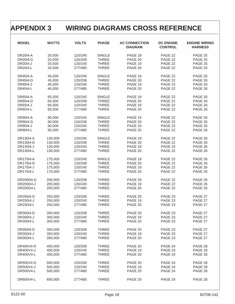
MODEL WATTS VOLTS PHASE AC CONNECTION DC ENGINE ENGINE WIRINGDIAGRAM CONTROL HARNESS
DR20I4-A 20,000 120/240 SINGLE PAGE 19 PAGE 22 PAGE 25DR20I4-D 20,000 120/208 THREE PAGE 20 PAGE 22 PAGE 25DR20I4-J 20,000 120/240 THREE PAGE 19 PAGE 22 PAGE 25DR20I4-L 20,000 277/480 THREE PAGE 20 PAGE 22 PAGE 25
DR45I4-A 45,000 120/240 SINGLE PAGE 19 PAGE 22 PAGE 26DR45I4-D 45,000 120/208 THREE PAGE 20 PAGE 22 PAGE 26DR45I4-J 45,000 120/240 THREE PAGE 19 PAGE 22 PAGE 26DR45I4-L 45,000 277/480 THREE PAGE 20 PAGE 22 PAGE 26
DR65I4-A 65,000 120/240 SINGLE PAGE 19 PAGE 22 PAGE 26DR65I4-D 65,000 120/208 THREE PAGE 20 PAGE 22 PAGE 26DR65I4-J 65,000 120/240 THREE PAGE 19 PAGE 22 PAGE 26DR65I4-L 65,000 277/480 THREE PAGE 20 PAGE 22 PAGE 26
DR90I4-A 90,000 120/240 SINGLE PAGE 19 PAGE 22 PAGE 26DR90I4-D 90,000 120/208 THREE PAGE 20 PAGE 22 PAGE 26DR90I4-J 90,000 120/240 THREE PAGE 19 PAGE 22 PAGE 26DR90I4-L 90,000 277/480 THREE PAGE 20 PAGE 22 PAGE 26
DR130I4-A 130,000 120/240 SINGLE PAGE 19 PAGE 22 PAGE 26DR130I4-D 130,000 120/208 THREE PAGE 20 PAGE 22 PAGE 26DR130I4-J 130,000 120/240 THREE PAGE 19 PAGE 22 PAGE 26DR130I4-L 130,000 277/480 THREE PAGE 20 PAGE 22 PAGE 26
DR175I4-A 175,000 120/240 SINGLE PAGE 19 PAGE 22 PAGE 26DR175I4-D 175,000 120/208 THREE PAGE 20 PAGE 22 PAGE 26DR175I4-J 175,000 120/240 THREE PAGE 19 PAGE 22 PAGE 26DR175I4-L 175,000 277/480 THREE PAGE 20 PAGE 22 PAGE 26
DR200D4-D 200,000 120/208 THREE PAGE 20 PAGE 22 PAGE 26DR200D4-J 200,000 120/240 THREE PAGE 19 PAGE 22 PAGE 26DR200D4-L 200,000 277/480 THREE PAGE 20 PAGE 22 PAGE 26
DR250I4-D 250,000 120/208 THREE PAGE 20 PAGE 23 PAGE 27DR250I4-J 250,000 120/240 THREE PAGE 19 PAGE 23 PAGE 27DR250I4-L 250,000 277/480 THREE PAGE 20 PAGE 23 PAGE 27
DR300I4-D 300,000 120/208 THREE PAGE 20 PAGE 23 PAGE 27DR300I4-J 300,000 120/240 THREE PAGE 19 PAGE 23 PAGE 27DR300I4-L 300,000 277/480 THREE PAGE 20 PAGE 23 PAGE 27
DR350I4-D 350,000 120/208 THREE PAGE 20 PAGE 23 PAGE 27DR350I4-J 350,000 120/240 THREE PAGE 19 PAGE 23 PAGE 27DR350I4-L 350,000 277/480 THREE PAGE 20 PAGE 23 PAGE 27
DR400V4-D 400,000 120/208 THREE PAGE 20 PAGE 24 PAGE 28DR400V4-J 400,000 120/240 THREE PAGE 19 PAGE 24 PAGE 28DR400V4-L 400,000 277/480 THREE PAGE 20 PAGE 24 PAGE 28
DR500V4-D 500,000 120/208 THREE PAGE 20 PAGE 24 PAGE 28DR500V4-J 500,000 120/240 THREE PAGE 19 PAGE 24 PAGE 28DR500V4-L 500,000 277/480 THREE PAGE 20 PAGE 24 PAGE 28
DR600V4-L 600,000 277/480 THREE PAGE 20 PAGE 24 PAGE 28
APPENDIX 3 WIRING DIAGRAMS CROSS REFERENCE

60708-142 Page 19 8122-00
TH
RE
E P
HA
SE
AC
WIR
ING
- D
ELT
AS
ING
LE
PH
AS
E A
C W
IRIN
GS
ING
LE
PH
AS
E12
0/24
0 V
OLT
ST
HR
EE
PH
AS
E -
DE
LTA
120/
240
VO
LTS

Page 208122-00 60708-142
TH
RE
E P
HA
SE
AC
WIR
ING
HIG
H A
ND
LO
W W
YETH
RE
E P
HA
SE
-LO
W W
YE
120/208 VO
LTS
TH
RE
E P
HA
SE
-HIG
H W
YE
277/480 VO
LTS

60708-142 Page 21 8122-00
ENGINE CONTROL DR20
60708-142Page 228122-00
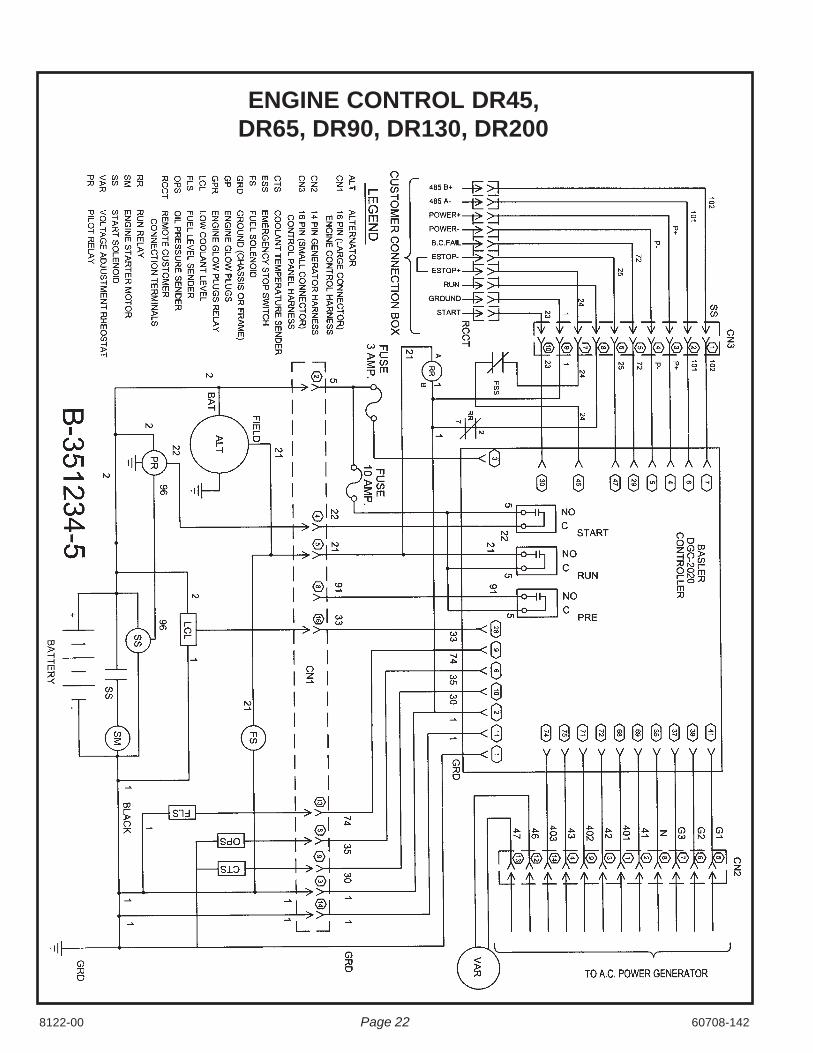
ENGINE CONTROL DR45,DR65, DR90, DR130, DR200

8122-0060708-142 Page 23
ENGINE CONTROL DR175, DR250, DR300, DR350
60708-142Page 248122-00
ENGINE CONTROL DR400, DR500, DR600,

8122-0060708-142 Page 25
EN
GIN
E W
IRIN
G H
AR
NE
SS
DR
20

60708-142Page 268122-00
EN
GIN
E W
IRIN
G H
AR
NE
SS
DR
45, DR
65, DR
90, DR
130, DR
200

8122-0060708-142 Page 27
EN
GIN
E W
IRIN
G H
AR
NE
SS
DR
175,
DR
250,
DR
300,
DR
350

60708-142Page 288122-00
EN
GIN
E W
IRIN
G H
AR
NE
SS
DR
400, DR
500, DR
600

8122-0060708-142 Page 29
MODEL BASE VOLTS PHASE WINCO P/N NEWAGE WINDING GENERATORP/N MODEL # GROUP LEADS
DR20I4-A 300545-1 120/240 SINGLE 350097-91 BCI184E 6 4DR20I4-D 300545-2 120/208 THREE 350097-9 BCI184E 311 12DR20I4-J 300545-2 120/240 THREE 350097-9 BCI184E 311 12DR20I4-L 300545-2 277/480 THREE 350097-9 BCI184E 311 12
DR45I4-A 351907-1 120/240 SINGLE 350003-731 UCI224E 6 4DR45I4-D 351907-2 120/208 THREE 350003-702 UCI224D 311 12DR45I4-J 351907-2 120/240 THREE 350003-702 UCI224D 311 12DR45I4-L 351907-2 277/480 THREE 350003-702 UCI224D 311 12
DR65I4-A 351924-1 120/240 SINGLE 350003-751 UCI224G 6 4DR65I4-D 351924-2 120/208 THREE 35000-704 UCI224F 311 12DR65I4-J 351924-2 120/240 THREE 35000-704 UCI224F 311 12DR65I4-L 351924-2 277/480 THREE 35000-704 UCI224F 311 12
DR90I4-A 351914-1 120/240 SINGLE 350004-711 UCI274C 6 4DR90I4-D 351914-2 120/208 THREE 350004-701 UCI274C 311 12DR90I4-J 351914-2 120/240 THREE 350004-701 UCI274C 311 12DR90I4-L 351914-2 277/480 THREE 350004-701 UCI274C 311 12
DR130I4-A 351949-1 120/240 SINGLE 350004-101 UCI274F 6 4DR130I4-D 351949-0 120/208 THREE 350004-710 UCI274F 311 12DR130I4-J 351949-0 120/240 THREE 350004-710 UCI274F 311 12DR130I4-L 351949-0 277/480 THREE 350004-710 UCI274F 311 12
DR175I4-A 351955-1 120/240 SINGLE 350004-106 UCI274H 6 4DR175I4-D 351955-0 120/208 THREE 350004-105 UCI274H 311 12DR175I4-J 351955-0 120/240 THREE 350004-105 UCI274H 311 12DR175I4-L 351955-0 277/480 THREE 350004-105 UCI274H 311 12
DR200D4-D 351973-1 120/208 THREE 350004-117 UCI274J 311 12DR200D4-J 351973-1 120/240 THREE 350004-117 UCI274J 311 12DR200D4-L 351973-1 277/480 THREE 350004-117 UCI274J 311 12
DR250I4-D 351937-1 120/208 THREE 350031-2 HCI434D 311 12DR250I4-J 351937-1 120/240 THREE 350031-2 HCI434D 311 12DR250I4-L 351937-1 277/480 THREE 350031-2 HCI434D 311 12
DR300I4-D 351943-1 120/208 THREE 350031-3 HCI434E 311 12DR300I4-J 351943-1 120/240 THREE 350031-3 HCI434E 311 12DR300I4-L 351943-1 277/480 THREE 350031-3 HCI434E 311 12
DR350I4-D 351957-2 120/208 THREE 350037-7 HCI434F 311 12DR350I4-J 351957-2 120/240 THREE 350037-7 HCI434F 311 12DR350I4-L 351957-1 277/480 THREE 350031-3 HCI343E 311 12
DR400V4-D 351945-2 120/208 THREE 351599-1 HCI534C 311 12DR400V4-J 351945-2 120/240 THREE 351599-1 HCI534C 311 12DR400V4-L 351945-1 277/480 THREE 350031-7 HCI434F 311 12
DR500V4-D 120/208 THREE 351599-3 HCI534E 311 12DR500V4-J 120/240 THREE 351599-3 HCI534E 311 12DR500V4-L 277/480 THREE 351599-2 HCI534D 311 12
DR600V4-L 277/480 THREE 351599-3 HCI534E 311 12
APPENDIX 4 GENERATOR CROSS REFERENCE

60708-142 - 8122-00
225 S. CordovaLe Center MN 56057Phone - 507-357-6707www:winpowerinc.com
������������ WINPOWER, Incorporated warrants to the original purchaser for 12 months or 1000 hours whichever occurs first, that goods manufactured or supplied by it will be free from defects in workman-ship and material, provided such goods are installed, operated and maintained in accordance withWINPOWER written instructions.
WINPOWER’s sole liability, and Purchaser’s sole remedy for a failure under this warranty, shall belimited to the repair of the product. At WINPOWER’s option, material found to be defective inmaterial or workmanship under normal use and service will be repaired or replaced. For warrantyservice, return the product within 12 months or 1000 hours which ever occurs first from the date ofpurchase, transportation charges prepaid, to your nearest WINPOWER Authorized Service Centeror to WINPOWER, Inc. at Le Center Minnesota.
THERE IS NO OTHER EXPRESS WARRANTY.
To the extent permitted by law, any and all warranties, including those of merchantability andfitness for a particular purpose, are limited to 12 months or 1000 hours which ever accurs first,from date of purchase. In no event is WINPOWER liable for incidental or consequential damages.
Note: Some states do not allow limitation on the duration of implied warranty and some states donot allow the exclusion or limitation of incidental or consequential damages, so the above limita-tions may not apply in every instance. This warranty gives you specific legal rights which may varyfrom state to state.
WINPOWER reserves the right to change or improve its products without incurring any obligationsto make such changes or improvement on products purchased previously.
EXCLUSIONS:
WINPOWER does not warrant Engines. Engines are covered exclusively by the warranties of theirrespective manufacturers, see enclosed warranties.
WINPOWER does not warrant Batteries, or Other Component Parts that are warranted by their respectivemanufacturers.
WINPOWER does not warrant modifications or alterations which were not made by WINPOWER, Inc.
WINPOWER does not warrant products which have been subjected to misuse and/or negligenceor �����been involved in an accident.