draft design standards (2) automated toll collection · (10) tcvn 4054:2005: highway -...
TRANSCRIPT
DRAFT DESIGN STANDARDS (2)
Automated Toll Collection
(Ver.1.0: Final Version of the Study Results)
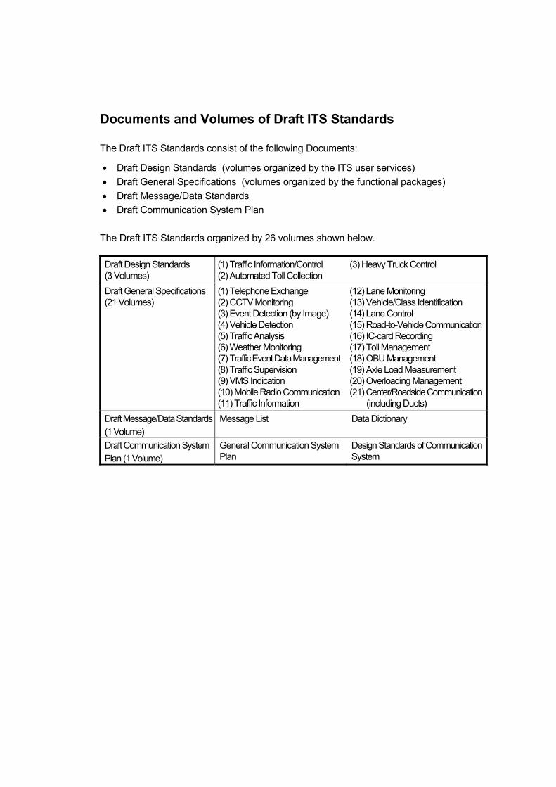
Documents and Volumes of Draft ITS Standards
The Draft ITS Standards consist of the following Documents:
• Draft Design Standards (volumes organized by the ITS user services) • Draft General Specifications (volumes organized by the functional packages) • Draft Message/Data Standards • Draft Communication System Plan
The Draft ITS Standards organized by 26 volumes shown below.
Draft Design Standards (3 Volumes)
(1) Traffic Information/Control (2) Automated Toll Collection
(3) Heavy Truck Control
Draft General Specifications (21 Volumes)
(1) Telephone Exchange (2) CCTV Monitoring (3) Event Detection (by Image) (4) Vehicle Detection (5) Traffic Analysis (6) Weather Monitoring (7) Traffic Event Data Management(8) Traffic Supervision (9) VMS Indication (10) Mobile Radio Communication(11) Traffic Information
(12) Lane Monitoring (13) Vehicle/Class Identification (14) Lane Control (15) Road-to-Vehicle Communication(16) IC-card Recording (17) Toll Management (18) OBU Management (19) Axle Load Measurement (20) Overloading Management (21) Center/Roadside Communication
(including Ducts) Draft Message/Data Standards (1 Volume)
Message List Data Dictionary
Draft Communication System Plan (1 Volume)
General Communication System Plan
Design Standards of CommunicationSystem
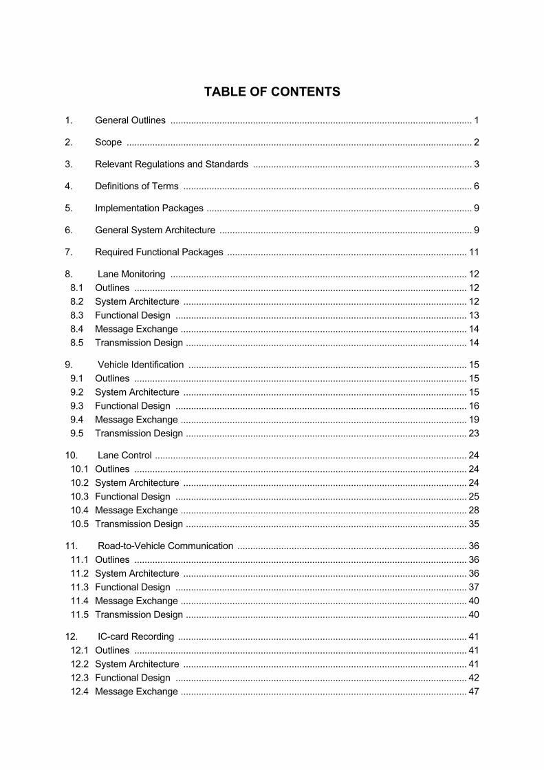
TABLE OF CONTENTS
1. General Outlines ..................................................................................................................... 1
2. Scope ...................................................................................................................................... 2
3. Relevant Regulations and Standards ..................................................................................... 3
4. Definitions of Terms ................................................................................................................ 6
5. Implementation Packages ....................................................................................................... 9
6. General System Architecture .................................................................................................. 9
7. Required Functional Packages ............................................................................................. 11
8. Lane Monitoring ................................................................................................................... 12 8.1 Outlines ................................................................................................................................. 12 8.2 System Architecture .............................................................................................................. 12 8.3 Functional Design ................................................................................................................. 13 8.4 Message Exchange ............................................................................................................... 14 8.5 Transmission Design ............................................................................................................. 14
9. Vehicle Identification ............................................................................................................ 15 9.1 Outlines ................................................................................................................................. 15 9.2 System Architecture .............................................................................................................. 15 9.3 Functional Design ................................................................................................................. 16 9.4 Message Exchange ............................................................................................................... 19 9.5 Transmission Design ............................................................................................................. 23
10. Lane Control ......................................................................................................................... 24 10.1 Outlines ................................................................................................................................. 24 10.2 System Architecture .............................................................................................................. 24 10.3 Functional Design ................................................................................................................. 25 10.4 Message Exchange ............................................................................................................... 28 10.5 Transmission Design ............................................................................................................. 35
11. Road-to-Vehicle Communication ......................................................................................... 36 11.1 Outlines ................................................................................................................................. 36 11.2 System Architecture .............................................................................................................. 36 11.3 Functional Design ................................................................................................................. 37 11.4 Message Exchange ............................................................................................................... 40 11.5 Transmission Design ............................................................................................................. 40
12. IC-card Recording ................................................................................................................ 41 12.1 Outlines ................................................................................................................................. 41 12.2 System Architecture .............................................................................................................. 41 12.3 Functional Design ................................................................................................................. 42 12.4 Message Exchange ............................................................................................................... 47

12.5 Transmission Design ............................................................................................................. 54
13. Toll Management ................................................................................................................. 55 13.1 Outlines ................................................................................................................................. 55 13.2 System Architecture .............................................................................................................. 55 13.3 Functional Design ................................................................................................................. 56 13.4 Message Exchange ............................................................................................................... 58 13.5 Transmission Design ............................................................................................................. 60
14. OBU Management ............................................................................................................... 61 14.1 Outlines ................................................................................................................................. 61 14.2 System Architecture .............................................................................................................. 61 14.3 Functional Design ................................................................................................................. 62 14.4 Message Exchange ............................................................................................................... 64 14.5 Transmission Design ............................................................................................................. 66
15. Location of Functional Packages ......................................................................................... 67
16. Preparation for Stepwise Implementation ............................................................................ 74

The Study for Supporting ITS Standards & Operation Plan Development in Vietnam Appendix 1
A1-(2) 1
1. General Outlines This volume of the Draft Design Standards defines basic concept and actualization method for designing the system of automated toll collection. The outlines of the service to be provided by non-stop toll collection can be described as below. This service enables toll collection without stopping vehicles: ETC (Electronic Toll Collection). This service relieves bottlenecks at the tollgates and allows smooth incoming and outgoing of vehicles at interchanges. This service reduces the number of tollbooths and solves the problem of land acquisition, especially for tollgates in suburban areas where traffic congestion will become an issue in near future. This service realizes simple vehicle inspection at the border crossings, and provides the road/vehicle operators with the time of vehicle passage at the tollgates. Computerized toll management can vastly reduce uncollected toll revenue due to the failure in counting/classifying vehicles and can realize appropriate sharing of the toll revenue among the different road operators.
This volume of the Draft Design Standards includes the following functional packages: (1) Lane Monitoring (2) Vehicle Identification (3) Lane Control (4) Road-to-Vehicle Communication (5) IC-card Recording (6) Toll Management (7) OBU Management.
In the Draft ITS Standards, the basic concept and actualization method of the system are defined according to the following basic contents:
1. General Outlines 2. Scope 3. Relevant Regulations and Standards 4. Definitions of Terms 5. Requirements 6. Implementation Packages 7. Particular Functional Package 7.1 Outlines 7.2 System Architecture 7.3 Functional Design 7.4 Message Exchange 7.5 Transmission Design 8. Location of Functional Packages 9. Preparation for Stepwise Implementation
The Study for Supporting ITS Standards & Operation Plan Development in Vietnam Appendix 1
A1-(2) 2
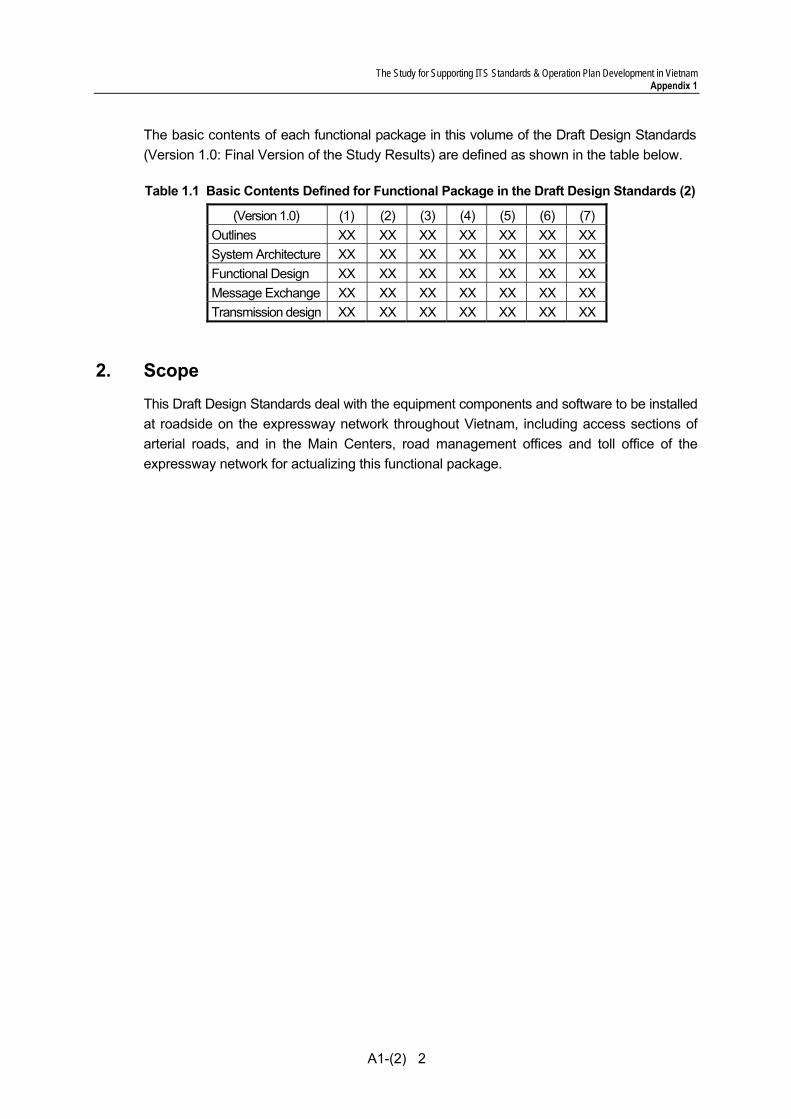
The basic contents of each functional package in this volume of the Draft Design Standards (Version 1.0: Final Version of the Study Results) are defined as shown in the table below.
Table 1.1 Basic Contents Defined for Functional Package in the Draft Design Standards (2)
(Version 1.0) (1) (2) (3) (4) (5) (6) (7) Outlines XX XX XX XX XX XX XX System Architecture XX XX XX XX XX XX XX Functional Design XX XX XX XX XX XX XX Message Exchange XX XX XX XX XX XX XX Transmission design XX XX XX XX XX XX XX
2. Scope
This Draft Design Standards deal with the equipment components and software to be installed at roadside on the expressway network throughout Vietnam, including access sections of arterial roads, and in the Main Centers, road management offices and toll office of the expressway network for actualizing this functional package.
The Study for Supporting ITS Standards & Operation Plan Development in Vietnam Appendix 1
A1-(2) 3
3. Relevant Regulations and Standards
The clauses in the Draft Standards of Automated Toll Collection are developed on the basis of or in reference to the following relevant regulations and standards. Some of the relevant regulations and standards need to be applied to specific ITS implementation projects in combination with the clauses in the Draft Standards of Automated Toll Collection.
(1) ISO 14813-1:2007 Intelligent transport systems – Reference model architecture(s) for the ITS centor – Part 1: ITS service domains, service groups and services
(2) IEC 60529: Degrees of Protection provided by Enclosure (IP Code) (3) ISO/IEC 14496-2 : Information technology -- Coding of audio-visual objects -- Part 2:
Visual (4) IEEE 802.3: Ethernet (Carrier Sense Multiple Access with Collision Detection) (5) BS 7430: 1998: Code of practice for earthing (6) BS 6651:1999 Lightning Protection (7) NEXCO Design Manual (8) ISO/DIS 14817: Transport information and control systems – requirements for an
ITS/TICS central data registry and ITS/TICS data dictionaries (9) ISO/IEC 11179: Information technology – specification and standardization of data
elements (10) TCVN 4054:2005: Highway - Specifications for Design (11) ISO/CD 24533: Data Dictionary and Message Set to Facilitate the Movement of
Freight and its Intermodal Transfer �Road Transport Information Exchanges for Supply Chain Freight Time-Sensitive Delivery (Road-Air Freight-Road)
(12) ITU-R M.1453: DSRC at 5.8GHz (Physical Layer) (13) ISO 15628: DSRC Applications (14) ISO 14906: Application Interface Definition for DSRC (15) EN 12253:2004: Road transport and traffic telematics – Dedicated short range
communication: – Physical Layer using microwave at 5.8 GHz (16) EN 13372:2004: Road transport and traffic telematics (RTTT) – Dedicated short range
communication – Profiles for RTTT application (17) EN 15509:2007: Road transport and traffic telematics (RTTT) – Electronic fee
collection interoperability application profile for DSRC (18) ISO/IEC 14443: Contact-less Integrated Circuit Cards (19) ISO/IEC 18092: Near Field Communication – Interface and protocol (20) ISO 15784-1 Intelligent transport systems (ITS) -- Data exchange involving roadside
modules communication -- Part 1: General principles and documentation framework of application profiles
(21) IETF/RFC 791, 768, 792, 793: Transmission Control Protocol/Internet Protocol v4 (TCP/IP v4)
(22) ISO 8877 (RJ-45) connector (23) ISO/IEC 15417:2007 Information technology -- Automatic identification and data
capture techniques -- Code 128 bar code symbology specification (24) ISO 14906:2004 Road transport and traffic telematics -- Electronic fee collection --
Application interface definition for dedicated short-range communication

The Study for Supporting ITS Standards & Operation Plan Development in Vietnam Appendix 1
A1-(2) 4
(25) ISO/TS 17573:2003 Road Transport and Traffic Telematics -- Electronic Fee Collection (EFC) -- Systems architecture for vehicle related transport services
(26) ISO/TS 14904:2002 Road transport and traffic telematics -- Electronic fee collection (EFC) -- Interface specification for clearing between operators
(27) ISO/TS14907-1:2010 Electronic fee collection -- Test procedures for user and fixed equipment -- Part 1: Description of test procedures
(28) ISO/TS 14907-2:2006 Road transport and traffic telematics -- Electronic fee collection -- Test procedures for user and fixed equipment -- Part 2: Conformance test for the onboard unit application interface
(29) ISO/TS 17574:2009 Electronic fee collection - Guidelines for security protection profiles
(30) ISO 14906:2004 Road transport and traffic telematics -- Electronic fee collection -- Application interface definition for dedicated short-range communication
(31) ISO/TS 25110:2008 Electronic fee collection -- Interface definition for on-board account using integrated circuit card (ICC)
(32) ISO 24097-1 Using Web Services(Machine-Machine Delivery) for ITS Service Delivery-Part 1: Realization of interoperable web services
(33) 22 TCN 331-05. Biển chỉ dẫn trên đường cao tốc (34) 06/2009/TT-BCA Quy định việc cấp, thu hồi đăng ký, biển số các loại phương tiện
giao thông cơ giới đường bộ
The requirement standardization criteria in Viet Nam and the referential relation with the relevant regulations/standards are summarized in the following table.
<Standardization Criteria> • National: To be standardized by the Government • Local: to be standardized by MOT
<Referential relation with the Relevant Regulations/Standards> • The clause is developed on the basic of ##: the relevant regulations/standards • The clause is developed originally in reference to ##: the relevant regulations/standards • The clause is to be applied specific ITS implementation project in combination/reference
with ##: the relevant regulations/standards.
Table 9.1 Standardization Criteria and Referential Relation with Relevant Regulation/Standards
Clause StandardizationCriteria
Referential Relation with Relevant Regulation/Standards
Lane Monitoring (8) • System Architecture (8.2) Local Developed on the basis of (1),
Developed originally in reference to (7) • Function design (8.3) Local Developed originally in reference to (7) and
(20) • Message Exchange (8.4) Local Developed originally in reference to (7)
Developed on the basis of (8) • Transmission design (8.5) Local Developed originally in reference to (3), (4)
and (21) Vehicle identification (9) • System Architecture (9.2) Local Developed on the basis of (1),
Developed originally in reference to (7)

The Study for Supporting ITS Standards & Operation Plan Development in Vietnam Appendix 1
A1-(2) 5
• Function design (9.3) Local Developed originally in reference to (7) Developed on the basis of (34)
• Message Exchange (9.4) Local Developed originally in reference to (7) Developed on the basis of (8)
• Transmission design (9.5) Local Developed originally in reference to (3), (4) and (21)
Lane control (10) • System Architecture (10.2) Local Developed on the basis of (1),
Developed originally in reference to (7) • Function design (10.3) Local Developed originally in reference to (7),
(23), (32) and (33) • Message Exchange (10.4) Local Developed originally in reference to (7)
Developed on the basis of (8) • Transmission design (10.5) Local Developed originally in reference to (4) and
(21) Road-to-Vehicle Communication (11)
• System Architecture (11.2) Local Developed on the basis of (1), Developed originally in reference to (7)
• Function design (11.3) Local Developed originally in reference to (7), (24), (27), (28), (29), (30) and (32)
• Message Exchange (11.4) Local Developed originally in reference to (7) Developed on the basis of (8)
• Transmission design (11.5) National Developed originally in reference to (4) and (21)
IC-Card Recording (12) • System Architecture (12.2) Local Developed on the basis of (1),
Developed originally in reference to (7) • Function design (12.3) Local Developed originally in reference to (7),
(18), (19), (31) and (32) • Message Exchange (12.4) National Developed originally in reference to (7)
Developed on the basis of (8) • Transmission design (12.5) National Developed originally in reference to (4) and
(21) Toll Management (13) • System Architecture (13.2) Local Developed on the basis of (1),
Developed originally in reference to (7) • Function design (13.3) Local Developed originally in reference to (7),
(25), (26) and (29) • Message Exchange (13.4) Local Developed originally in reference to (7)
Developed on the basis of (8) • Transmission design (13.5) Local Developed originally in reference to (4) and
(21) OBU Management (14) • System Architecture (14.2) Local Developed on the basis of (1),
Developed originally in reference to (7) • Function design (14.3) Local Developed originally in reference to (7),
(25) and (34) • Message Exchange (14.4) Local Developed originally in reference to (7)
Developed on the basis of (8) • Transmission design (14.5) Local Developed originally in reference to (4) and
(21)
The Study for Supporting ITS Standards & Operation Plan Development in Vietnam Appendix 1
A1-(2) 6
Location of Functional Packages (15) Local Developed originally in reference to (7)
Preparation for Stepwise Implementation (16) Local Developed originally
4. Definitions of Terms
• CCTV Camera: Closed-Circuit Television Camera, which is used for producing images or recordings for surveillance purposes, and can be either video camera, or digital stills camera. Video cameras are either analogue or digital, so that they work on the basis of sending analogue or digital signals to a storage device such as a video tape recorder or computer. Video cameras are network cameras or IP cameras when embedded a video server having an IP address for video and audio streaming.
• CCTV Monitoring: This functional package allows the road operators to capture current situation of traffic accidents, broken-down vehicles, left obstacles, driving in the reverse direction, vandalism, natural disaster and traffic conditions on the expressways and to monitor the captured video image at the Main Centers and road management offices by using cameras installed at road sections where traffic can be stuck easily by incidents and at long tunnel sections.
• Data Element: A unit of data for which the definition, identification, representation and permissible values are specified by means of a set of attributes.
• Data Set: A set of data elements included in a message with a strong relationship among them.
• Draft Design Standards: One of the document of the Draft ITS Standards, which defines basic concept, general architecture and actualization method as a unified form for designing the system.
• Draft General Specifications: The Draft General Specifications defines required processing functions, performance, interfaces and installation of equipment in order to establish compatibility of equipment components.
• Draft Message/Data Standards: The Draft Message/Data Standards defines message list and data dictionary in order to establish inter-operability of message and data.
• DSRC: Dedicated Short Range Communications (DSRC), which allows high-speed communications between vehicles and the roadside, or between vehicles, for ITS.
• Equipment Component: The lowest subsystem of the system architecture, which is defined as the ordering unit for suppliers. Particulars of the Draft General Specifications are to be set up corresponding to the equipment components.
• ETC: Electronic Toll Collection (ETC), which is a toll collection method that eliminates the need for cash, tokens or credit cards to be used at tollbooths. Vehicles are equipped with small electronic devices that transmit both vehicle and account details through a reader located in the toll lane. The appropriate toll is then debited from the driver's prepaid account.
The Study for Supporting ITS Standards & Operation Plan Development in Vietnam Appendix 1
A1-(2) 7
• Flat Tariff System: A toll rate system in which fixed rates by vehicle class are applied to each vehicle passage through a road section independently of distance. This is the most simple toll rate system and is suitable for the toll collection on a particular road section or an urban toll road network in which route selection is to be required.
• Functional Package: A group of subsystems that have strong relationship to realize a certain function. Particulars of the Draft Design Standards and volumes of the Draft General Specifications are to be set up corresponding to the functional packages.
• IC-Card Recording: This functional package allows the road operators to deduct prepaid balance of IC-cards for collecting toll by using equipment installed at tollgates on the expressways.
• IC-card: Integrated Circuit card, which is any pocket-sized card with embedded integrated circuits. There are two broad categories of IC-Cards. Memory cards contain only non-volatile memory storage components. Microprocessor cards contain volatile memory and microprocessor components. The card is used for identification or financial transaction.
• Image Recognition: Software technology that uses computer algorithms to intelligently monitor real-time video for automatically recognizing license plate number of vehicle, vehicle speed, the occurrence of traffic accidents, broken-down vehicles, and left obstacles.
• Interchange: A junction connecting an expressway network and an arterial road network. That comprises grade separation and ramps to permit traffic on the expressway to pass through the junction without directly crossing other traffic on the arterial road.
• Interface: a connection for distributing information between two different subsystems, or between a subsystem and an object outside of ITS, and that is important target for discussing the standardization.
• ISO: The International Organization for Standardization is an international-standard-setting body composed of representatives from various national standards organizations. Founded on February 23, 1947, the organization promulgates worldwide proprietary industrial and commercial standards.
• ITS User Service: A service to be provided by an ITS application to the users directly or indirectly.
• ITS: Intelligent Transport Systems (ITS) are systems to support transportation of goods and humans with information and communication technologies in order to efficiently and safely use the transport infrastructure and transport means (cars, trains, planes, ships...)
• ITU: The International Telecommunication Union is an agency of the United Nations which regulates information and communication technology issues. ITU coordinates the shared global use of the radio spectrum, promotes international cooperation in assigning satellite orbits, works to improve telecommunication infrastructure in the developing world and establishes worldwide standards.
• Lane Control: This functional package allows the road operators to eliminate the vehicle passages without adequate toll collection by using a computer, vehicle detectors, signs and a barrier installed in a separated tollgate lane of the expressway.
The Study for Supporting ITS Standards & Operation Plan Development in Vietnam Appendix 1
A1-(2) 8
• Lane Monitoring: This functional package allows the road operators to monitor current conditions of vehicle passage and operations by workers by using cameras installed in a separated lane such as a tollgate lane of the expressway.
• Main Center: The Center in charge of traffic monitoring, traffic control and traffic information dissemination, and is to be cooperated with road management offices.
• Message: A set of data to be exchanged between subsystems for transferring information.
• Node: A node is a connection point is a connection point, either a redistribution point or a communication endpoint (some terminal equipment). The definition of a node depends on the network and protocol layer referred to. A physical network node is an active electronic device that is attached to a network, and is capable of sending, receiving, or forwarding information over a communications channel
• Non-stop Toll Collection: An ITS user service for enabling toll payment without the need to stop the vehicle at the tollgates, allowing smooth incoming and outgoing of vehicles at the interchanges, increasing the vehicle processing capacity of the tollgate and reducing the number of tollbooths and land acquisition.
• OBU Management: This functional package allows to register on-board units by using equipment installed in OBU issue offices, and allows to generate/manage the registration list and the invalidation list of on-board units by using computers and software installed in the OBU registration center.
• OBU: On-Board Unit. The in-vehicle device component of an ETC system. A receiver or transceiver permitting the Operator’s Roadside Unit (RSU) to communicate with, identify, and conduct an electronic toll transaction; also called a ‘transponder’ or ‘tag.’
• Road Management Office: An office in charge of patrol for surveying current traffic conditions on the expressway, and is to be equipped with the operation vehicles and the monitoring equipment for surveillance.
• Road-to-Vehicle Communication: This functional package allows the road operators to exchange data for toll collection and other services on the expressways by using radio communication between antennas installed at roadside and on-board units installed in the vehicles.
• SDH: Synchronous Digital Hierarchy are standardized multiplexing protocols that transfer multiple digital bit streams over optical fiber using lasers or light-emitting diodes (LEDs). Lower data rates can also be transferred via an electrical interface.
• System Architecture: Diagrams indicated by the combination of subsystems and interfaces necessary for realizing a large system such as ITS. That should consist of several different kinds of diagrams, such as collaboration diagrams and message sequence diagrams in the notation of UML (Unified Modelling Language).
• Toll Management: This functional package allows the road operators to keep all data of toll collection, to manage the invalidation list on the usage of on-board units and IC-cards, and to manage toll revenue of the expressways with a high reliability by using computers and software installed in the road management office.

The Study for Supporting ITS Standards & Operation Plan Development in Vietnam Appendix 1
A1-(2) 9
• Toll Office: A toll office is located at a tollgate, which includes two or more tollbooths, and is in charge of toll collection.
• Touch&Go: A toll payment method using a prepaid balance in IC-Card. Information contain in this card can be read and written via magnetic induction using specified radio frequency and IC-Card software. Each time passing through a tollgate, road user uses the IC-Card, the electronic card reader will deduct the exact fare from the value stored inside the card. User can top-up or reload the card with a pre-defined amount to continue using it.
• Vehicle Class: A set of categories of vehicles for toll collection, traffic data or overloading regulation with definition of unique name/identifier to be applied to each category.
• Vehicle Detector: A sensor either embedded in the pavement or mounted above the expressway to provide vehicle volume, speed, counts, headway, queue lengths, and vehicle classifications.
• Vehicle Identification: This functional package allows the road operators to identify individual vehicle by using a license plate scanner and other equipment installed in a separated lane such as a tollgate lane of the expressway.
• VMS Indication: This functional package allows the road operators to provide road users on the expressways with the information organized as traffic events by using VMS (Variable Message Sign) installed at the place short of entrances, exits, tollgates, junctions and tunnels.
5. Implementation Packages
The system for automated toll collection comprises the following implementation packages:
(1) Toll Collection (2) Center-to-center data exchange
Figure 6.1 Implementation Packages and Alternatives of Automated Toll Collection
6. General System Architecture
Diagrams of general system architecture of the implementation packages of Automated Toll Collection are shown in the following page.
Non-Stop Toll Collection
Toll Collection
(ITS User Service) (Implementation Package) (Alternatives)
(a) by Touch&Go/Manual (b) by ETC at Toll-Island (2p-OBU)
Center-to-Center Data Exchange1. for Toll Settlement 2. for IC-Card Operation 3. for OBU Management

The Study for Supporting ITS Standards & Operation Plan Development in Vietnam Appendix 1
A1-(2) 10
Figure 5.1 Toll Collection by Touch&Go/Manual (G.S.A.)
Figure 5.2 Toll Collection by ETC at Toll Island (G.S.A.)
The Study for Supporting ITS Standards & Operation Plan Development in Vietnam Appendix 1
A1-(2) 11
7. Required Functional Packages
The following functional packages are required for structuring the system for automated toll collection system: (1) Lane Monitoring (2) Vehicle Classification (3) Lane Control (4) Road-to-Vehicle Communication (5) IC-card Recording (6) Toll Management (7) OBU Management.

The Study for Supporting ITS Standards & Operation Plan Development in Vietnam Appendix 1
A1-(2) 12
8. Lane Monitoring
8.1 Outlines This functional package allows the road operators to monitor current conditions of vehicle passage and operations by workers by using cameras installed in a separated lane such as a tollgate lane of the expressway.
8.2 System Architecture
Figure 8.1 System Architecture for Lane Monitoring
Roadside Toll Management Office
CCTV Monitoring Console
Toll Booth/Roadside
CCTV Camera
Monitor Screen
Printer
CCTV Monitoring in Booth
: Switching Hub & Media Converter : Media Converter
: SDH Node
: Equipment Package : Location : Detailed Device
: Fibre Optic Cable : Copper Cable
Broken Lines: Outside of This Functional Package
: Software
Data Server
Lane Server
Text Data Indication Processor
The Study for Supporting ITS Standards & Operation Plan Development in Vietnam Appendix 1
A1-(2) 13
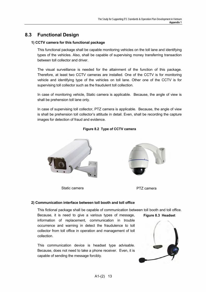
8.3 Functional Design 1) CCTV camera for this functional package
This functional package shall be capable monitoring vehicles on the toll lane and identifying types of the vehicles. Also, shall be capable of supervising money transferring transaction between toll collector and driver.
The visual surveillance is needed for the attainment of the function of this package. Therefore, at least two CCTV cameras are installed. One of the CCTV is for monitoring vehicle and identifying type of the vehicles on toll lane. Other one of the CCTV is for supervising toll collector such as the fraudulent toll collection.
In case of monitoring vehicle, Static camera is applicable. Because, the angle of view is shall be prehension toll lane only.
In case of supervising toll collector, PTZ camera is applicable. Because, the angle of view is shall be prehension toll collector’s attitude in detail. Even, shall be recording the capture images for detection of fraud and evidence.
Figure 8.2 Type of CCTV camera
Static camera
PTZ camera
2) Communication interface between toll booth and toll office
This fictional package shall be capable of communication between toll booth and toll office. Because, it is need to give a various types of message, information of replacement, communication in trouble occurrence and warning in detect the fraudulence to toll collector from toll office in operation and management of toll collection.
This communication device is headset type advisable. Because, does not need to take a phone receiver. Even, it is capable of sending the message forcibly.
Figure 8.3 Headset
The Study for Supporting ITS Standards & Operation Plan Development in Vietnam Appendix 1
A1-(2) 14
8.4 Message Exchange Refer to Section 10.4
8.5 Transmission Design The video data is transferred via Mpeg4-Partt and all other signals and data are transferred via Internet and communication Protocol is transferred via TCP/IP.
The system is constructed after disclosing the availability of trouble, necessary information, procedure and Interface software according to the self-diagnosis by center side equipment on sensors installed at roadside.
Further concepts and methodologies are to be referred to the Draft Communication System Plan.
The Study for Supporting ITS Standards & Operation Plan Development in Vietnam Appendix 1
A1-(2) 15
9. Vehicle Identification
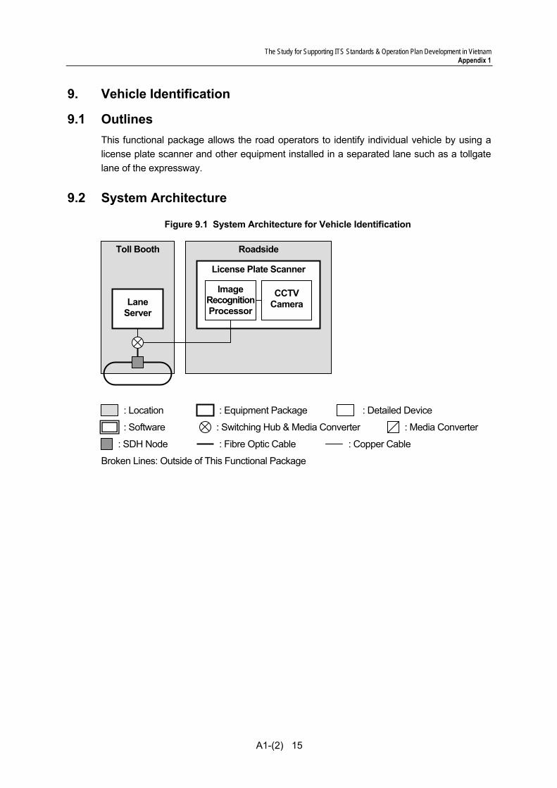
9.1 Outlines This functional package allows the road operators to identify individual vehicle by using a license plate scanner and other equipment installed in a separated lane such as a tollgate lane of the expressway.
9.2 System Architecture
Figure 9.1 System Architecture for Vehicle Identification
Toll Booth Roadside
: Switching Hub & Media Converter : Media Converter
: SDH Node
: Equipment Package : Location : Detailed Device
: Fibre Optic Cable : Copper Cable
Broken Lines: Outside of This Functional Package
: Software
License Plate Scanner
CCTV Camera
Image RecognitionProcessor
Lane Server
The Study for Supporting ITS Standards & Operation Plan Development in Vietnam Appendix 1
A1-(2) 16
9.3 Functional Design 1) License Plate Scanner
License Plate Scanner (other name Automatic Number Plate Recognition) is a mass surveillance method that uses optical character recognition on images to read the license plates on vehicles. They can use existing CCTV camera.
License Plate Scanner can be used to store the images captured by the cameras as well as the text from the license plate, with some configurable to store a photograph of the driver. Systems commonly use infrared lighting to allow the camera to take the picture at any time of the day. License Plate Scanner technology tends to be region-specific, owing to plate variation from place to place.
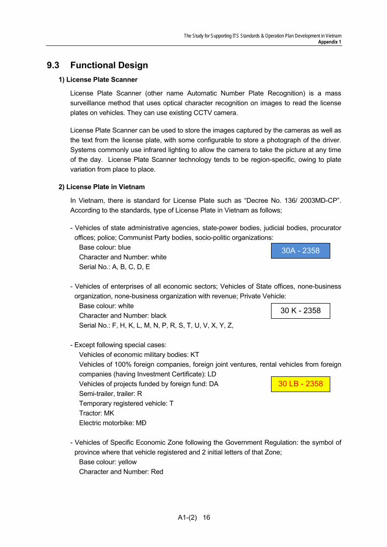
2) License Plate in Vietnam
In Vietnam, there is standard for License Plate such as “Decree No. 136/ 2003MD-CP”. According to the standards, type of License Plate in Vietnam as follows;
- Vehicles of state administrative agencies, state-power bodies, judicial bodies, procurator offices; police; Communist Party bodies, socio-politic organizations:
Base colour: blue Character and Number: white Serial No.: A, B, C, D, E
- Vehicles of enterprises of all economic sectors; Vehicles of State offices, none-business
organization, none-business organization with revenue; Private Vehicle: Base colour: white Character and Number: black Serial No.: F, H, K, L, M, N, P, R, S, T, U, V, X, Y, Z,
- Except following special cases:
Vehicles of economic military bodies: KT Vehicles of 100% foreign companies, foreign joint ventures, rental vehicles from foreign companies (having Investment Certificate): LD Vehicles of projects funded by foreign fund: DA Semi-trailer, trailer: R Temporary registered vehicle: T Tractor: MK Electric motorbike: MĐ
- Vehicles of Specific Economic Zone following the Government Regulation: the symbol of
province where that vehicle registered and 2 initial letters of that Zone; Base colour: yellow Character and Number: Red
30A - 2358
30 K - 2358
30 LB - 2358
The Study for Supporting ITS Standards & Operation Plan Development in Vietnam Appendix 1
A1-(2) 17
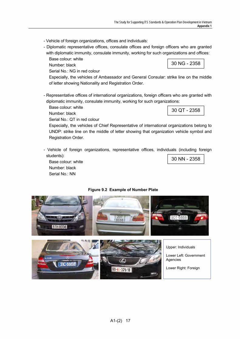
- Vehicle of foreign organizations, offices and individuals: - Diplomatic representative offices, consulate offices and foreign officers who are granted
with diplomatic immunity, consulate immunity, working for such organizations and offices: Base colour: white Number: black Serial No.: NG in red colour Especially, the vehicles of Ambassador and General Consular: strike line on the middle of letter showing Nationality and Registration Order.
- Representative offices of international organizations, foreign officers who are granted with
diplomatic immunity, consulate immunity, working for such organizations: Base colour: white Number: black Serial No.: QT in red colour Especially, the vehicles of Chief Representative of international organizations belong to UNDP: strike line on the middle of letter showing that organization vehicle symbol and Registration Order.
- Vehicle of foreign organizations, representative offices, individuals (including foreign
students): Base colour: white Number: black Serial No.: NN
Figure 9.2 Example of Number Plate
Upper: Individuals Lower Left: Government Agencies Lower Right: Foreign
30 NG - 2358
30 QT - 2358
30 NN - 2358

The Study for Supporting ITS Standards & Operation Plan Development in Vietnam Appendix 1
A1-(2) 18
. 2) Notabilia of License Plate Scanner for accuracy control
License Plate Scanner recognize the capture images from CCTV camera, the accuracy of recognition is effective depend on the quality of capture images.
Therefore, the capture images shall be capable taking appropriately. The factor of accuracy lowering is shown in the table below.
Table 9.1 Factor of accuracy lowering
Factor Definition Provision Machine Factor
Accident on automatic correctrion
The accident on automatic correction functions such as auto-focus, auto-iris due to some kind of factor.
Periodical maintenace
Environment Factor
Sudden mutation of sunlight
The glare by reflection of sunlight on License Plate. Sudden mutation of sunlight, such as appear from behind the clouds or not.
Automatic correction function allows to adjust in some cases
Hidden the Plate by other cars
The License Plate is hidden due to the distance between two cars is too short.
Adjustment of Angle of view
Rain Road surface is dreched with rain. The timing of capture is misaligned due to the head-light of vehicle is reflection on road surface. (Especially, night time)
See the detail as below;
User Factor Veiled License Plate
License Plate unreadable due to veiled with mud, soil and etc.
Unequipped License Plate is unequipped
License Plate Scanner has to detect approach the vehicle due to the change of the image using image recognition technology. However, in case of the road surface is drenched by rain, the road reflects the headlights. (See Figure 9.3) License Plate Scanner captures the image of vehicle when the reflected headlight approached.
Figure 9.3 Accuracy lowering due to the rain
Originally, the image capture at this timing
Detection as a reflection of the headlights of approach the vehicle
Image capture is at premature timing.
The Study for Supporting ITS Standards & Operation Plan Development in Vietnam Appendix 1
A1-(2) 19
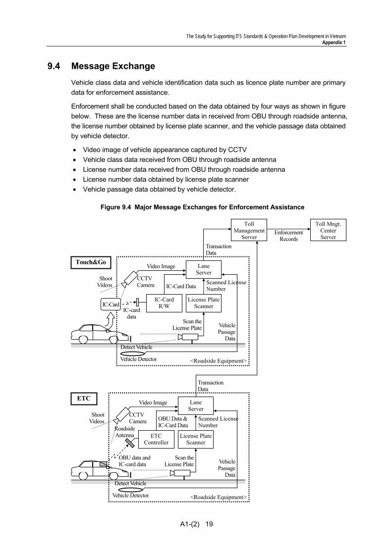
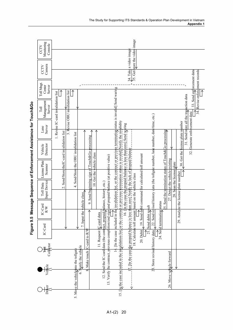
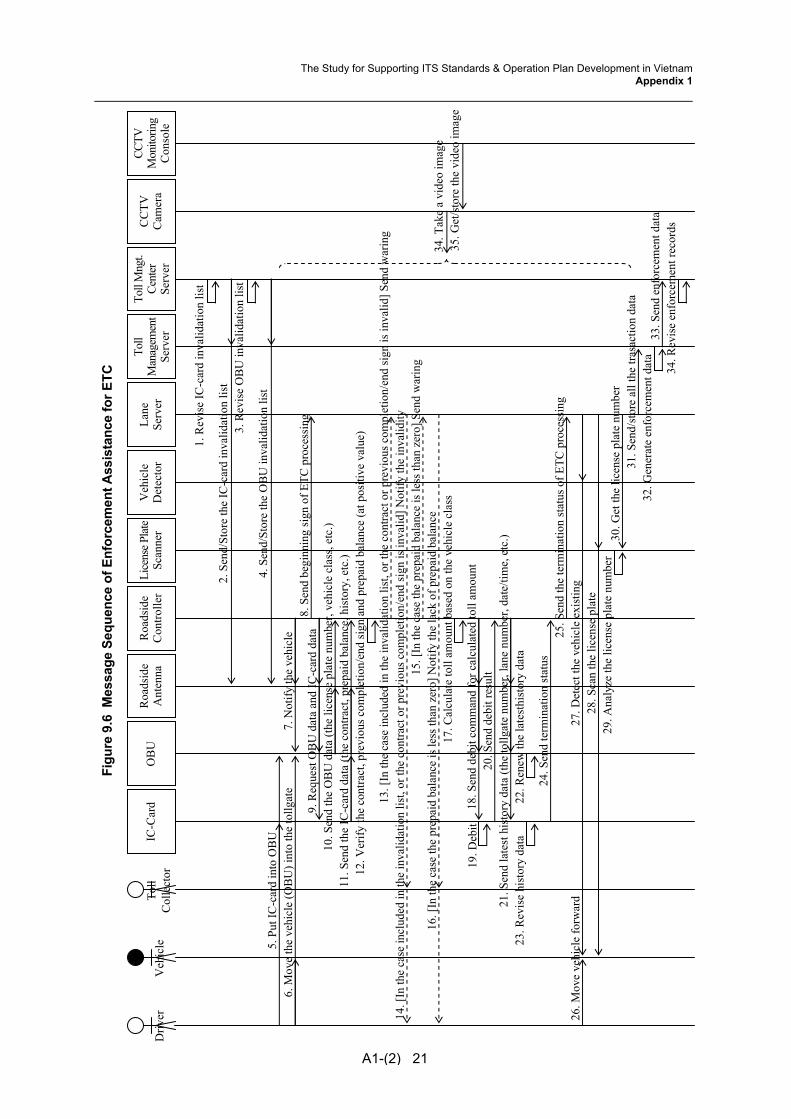
9.4 Message Exchange Vehicle class data and vehicle identification data such as licence plate number are primary data for enforcement assistance.
Enforcement shall be conducted based on the data obtained by four ways as shown in figure below. These are the license number data in received from OBU through roadside antenna, the license number obtained by license plate scanner, and the vehicle passage data obtained by vehicle detector.
• Video image of vehicle appearance captured by CCTV • Vehicle class data received from OBU through roadside antenna • License number data received from OBU through roadside antenna • License number data obtained by license plate scanner • Vehicle passage data obtained by vehicle detector.
Figure 9.4 Major Message Exchanges for Enforcement Assistance
Enforcement Records
Roadside Antenna ETC
Controller
LaneServer
OBU data and IC-card data
OBU Data &IC-Card Data
License PlateScanner
Scan theLicense Plate
Scanned LicenseNumber
VehiclePassage
DataDetect Vehicle
CCTV Camera
Shoot Videos
Video Image
Vehicle Detector <Roadside Equipment>
Toll Mngt.Center Server
TollManagement
Server
IC-CardR/W
LaneServer
License PlateScanner
Scan theLicense Plate Vehicle
PassageData
Detect Vehicle
CCTV Camera
Shoot Videos
Video Image
Vehicle Detector <Roadside Equipment>
IC-card data
IC-Card
IC-Card DataScanned LicenseNumber
TransactionData
TransactionData
Touch&Go
ETC
Figu
re 9
.5 M
essa
ge S
eque
nce
of E
nfor
cem
ent A
ssis
tanc
e fo
r Tou
ch&
Go
A1-(2) 20
Toll
Dat
aIn
put D
evic
eTo
ll M
ngt.
Cent
er
Serv
er
Lane
Serv
er
IC-C
ard
R/W
D
river
12. S
end
the
IC-c
ard
data
(the
con
tract
, pre
paid
bal
ance
, his
tory
, etc
.)
5. M
ove
the
vehi
clei
nto
the
tollg
ate
6. N
otify
the
vehi
cle
9. S
end
begi
nnin
g si
gn o
f Tou
ch&
Go
proc
essi
ng
11. R
eque
st IC
-car
d da
ta
20. D
ebit
Toll
Man
agem
ent
Serv
er
Toll
Col
lect
or
IC-C
ard
Veh
icle
21. S
end
debi
t res
ult
24. S
end
term
inat
ion
stat
us
22. S
end
revi
sed
hist
ory
data
(the
tollg
ate
num
ber,
lane
num
ber,
date
/tim
e, e
tc.)
23. S
tore
revi
sed
hist
ory
data
31. S
end/
stor
e al
l the
tras
actio
n da
ta
7. In
put t
he v
ehic
le c
lass
8. M
ake
touc
h IC
-car
d to
R/W
25. S
end
the
term
inat
ion
stat
us o
f Tou
ch&
Go
proc
essi
ng
10. G
et th
e ve
hicl
e cl
ass
19. S
end
debi
t com
man
d fo
r cal
cula
ted
toll
amou
nt
18. C
alcu
late
toll
amou
nt b
ased
on
the
vehi
cle
clas
s
14. [
In th
e ca
se in
clud
ed in
the
inva
lidat
ion
list,
or th
e co
ntra
ct o
r pre
viou
s ter
min
atio
n st
atus
is in
valid
] Sen
d w
arin
g15
. [In
the
case
incl
uded
in th
e in
valid
atio
n lis
t, or
the
cont
ract
or p
revi
ous t
erm
inat
ion
stat
us is
inva
lid] N
otify
the
inva
lidity
16. [
In th
e ca
se th
e pr
epai
d ba
lanc
e is
less
than
zer
o] S
end
war
ing
17. [
In th
e ca
se th
e pr
epai
d ba
lanc
e is
less
than
zer
o] N
otify
the
lack
of p
repa
id b
alan
ce
13. V
erify
the
cont
ract
, pre
viou
s com
plet
ion/
end
sign
and
pre
paid
bal
ance
(at p
ositi
ve v
alue
)
4. S
end/
Stor
e th
e O
BU
inva
lidat
ion
list
1. R
evis
e IC
-car
d in
valid
atio
n lis
t
CCTV
Mon
itorin
gC
onso
le
CC
TVC
amer
a
33. S
end
enfo
rcem
ent d
ata
32. G
ener
ate
enfo
rcem
ent d
ata
Lice
nse P
late
Scan
ner
Veh
icle
D
etec
tor
26. M
ove
vehi
cle
forw
ard
27. D
etec
t the
veh
icle
exi
stin
g28
. Sca
n th
e lic
ense
pla
te29
. Ana
lyze
the
licen
se p
late
num
ber
30. G
et th
e lic
ense
pla
te n
umbe
r
34. T
ake
a vi
deo
imag
e35
. Get
/sto
re th
e vi
deo
imag
e
2. S
end/
Stor
e th
eIC
-car
d in
valid
atio
n lis
t3.
Rev
ise
OB
U in
valid
atio
n lis
t
34. R
evis
e en
forc
emen
t rec
ords
The Study for Supporting ITS Standards & Operation Plan Development in VietnamAppendix 1
Figu
re 9
.6 M
essa
ge S
eque
nce
of E
nfor
cem
ent A
ssis
tanc
e fo
r ETC
A1-(2) 21
Roa
dsid
eC
ontro
ller
Toll
Mng
t.Ce
nter
Se
rver
Lane
Serv
er
OB
UR
oads
ide
Ant
enna
Driv
er
11. S
end
the
IC-c
ard
data
(the
con
tract
, pre
paid
bal
ance
, his
tory
, etc
.)12
. Ver
ify th
e co
ntra
ct, p
revi
ous c
ompl
etio
n/en
d si
gn a
nd p
repa
id b
alan
ce (a
t pos
itive
val
ue)
18. S
end
debi
t com
man
d fo
r cal
cula
ted
toll
amou
nt
5. P
ut IC
-car
d in
to O
BU
6.
Mov
e th
e ve
hicl
e (O
BU
) int
o th
e to
llgat
e7.
Not
ify th
e ve
hicl
e8.
Sen
d be
ginn
ing
sign
of E
TC p
roce
ssin
g9.
Req
uest
OB
U d
ata
and
IC-c
ard
data
10. S
end
the
OB
U d
ata
(the
licen
se p
late
num
ber,
vehi
cle
clas
s, et
c.)
33. S
end
enfo
rcem
ent d
ata
32. G
ener
ate
enfo
rcem
ent d
ata
17. C
alcu
late
toll
amou
nt b
ased
on
the
vehi
cle
clas
s 19
. Deb
it
Toll
Man
agem
ent
Serv
er
Toll
Col
lect
or
IC-C
ard
Veh
icle
20. S
end
debi
t res
ult
22. R
enew
the
late
sthi
stor
y da
ta
24. S
end
term
inat
ion
stat
us
21. S
end
late
st h
isto
ry d
ata
(the
tollg
ate
num
ber,
lane
num
ber,
date
/tim
e, e
tc.)
23. R
evis
e hi
stor
y da
ta
25. S
end
the
term
inat
ion
stat
us o
f ETC
pro
cess
ing
31. S
end/
stor
e al
l the
tras
actio
n da
ta
15. [
In th
e ca
se th
e pr
epai
d ba
lanc
e is
less
than
zer
o] S
end
war
ing
16. [
In th
e ca
se th
e pr
epai
d ba
lanc
e is
less
than
zer
o] N
otify
the
lack
of p
repa
id b
alan
ce
4. S
end/
Stor
e th
e O
BU
inva
lidat
ion
list
13. [
In th
e ca
se in
clud
ed in
the
inva
lidat
ion
list,
or th
e co
ntra
ct o
r pre
viou
s com
plet
ion/
end
sign
is in
valid
] Sen
d w
arin
g14
. [In
the
case
incl
uded
in th
e in
valid
atio
n lis
t, or
the
cont
ract
or p
revi
ous c
ompl
etio
n/en
d si
gn is
inva
lid] N
otify
the
inva
lidity
CCTV
M
onito
ring
Con
sole
CC
TVC
amer
a Li
cens
e Plat
eSc
anne
r V
ehic
leD
etec
tor
26. M
ove
vehi
cle
forw
ard
27. D
etec
t the
veh
icle
exi
stin
g28
. Sca
n th
e lic
ense
pla
te29
. Ana
lyze
the
licen
se p
late
num
ber
30. G
et th
e lic
ense
pla
te n
umbe
r
34. T
ake
a vi
deo
imag
e35
. Get
/sto
re th
e vi
deo
imag
e
2. S
end/
Stor
e th
e IC
-car
d in
valid
atio
n lis
t
1. R
evis
e IC
-car
d in
valid
atio
n lis
t
3. R
evis
e O
BU
inva
lidat
ion
list
34. R
evis
e en
forc
emen
t rec
ords
The Study for Supporting ITS Standards & Operation Plan Development in VietnamAppendix 1

The Study for Supporting ITS Standards & Operation Plan Development in Vietnam Appendix 1
A1-(2) 22
Data frame and principal data elements for toll enforcement are shown in the table below.
Table 9.2 Principal Data Elements for Enforcement Assistance
Data Set Principal Data Element Update Cycle Storage Period
Data Unit
Numberof Data
Enforcement Tollgate ID Each vehicle passing 1 year 100B 5 mil
record data set Lane server ID Each vehicle passing 1 year
Date/time Each vehicle passing 1 year
OBU ID Each vehicle passing 1 year
Vehicle class (by OBU) Each vehicle passing 1 year
License number (by OBU) Each vehicle passing 1 year
License number (by scan) Each vehicle passing 1 year
Enforcement status Each vehicle passing 1 year
License plate image data Each vehicle passing 1 year 50KB 5 mil
Enforcement status can be estimated by verifying the data in the table above.
Table 9.3 Enforcement Status by Estimated Verifying Data Roadside Antenna
License Plate Scanner
Vehicle Detector Enforcement Status CCTV
Camera LN LN LN Image Vehicle Passage Successful toll collection Video Image
LN LN LN Image - Successful toll collection Video Image
LN - - Vehicle Passage Successful toll collection Video Image
LN - - - Successful toll collection Video Image
LN Different LN LN Image Vehicle Passage Suspicion of spoofing * Video Image
LN Different LN LN Image - Suspicion of spoofing * Video Image
- LN LN Image Vehicle Passage Suspicion of violation ** Video Image
- LN LN Image - Suspicion of violation ** Video Image
- - - Vehicle Passage Suspicion of violation *** Video Image
- - - - No vehicle passage Video Image
Note, LN : License number
: Relevant data to be verified
* : Validity of the license number data obtained by the scanner shall be checked visually by the license number image from the scanner and the video image from CCTV camera of the tollgate. Where valid, the vehicle owner corresponding to the license number shall be treated as a suspect of spoofing: re-installing OBU from other vehicle.
** : Passage of the vehicle corresponding to the license number obtained by the scanner shall be checked visually by the license number image from the scanner and the video image from CCTV camera of the tollgate. Where true, the vehicle owner corresponding to the license number shall be treated as a suspect of violation: passing without OBU.
*** : Vehicle passage corresponding to the data obtained by the detector shall be checked visually by the video image from CCTV camera of the tollgate. Where true, the vehicle owner corresponding to the license number shall be treated as a suspect of violation.

The Study for Supporting ITS Standards & Operation Plan Development in Vietnam Appendix 1
A1-(2) 23
9.5 Transmission Design The video data is transferred via Mpeg4-Partt and all other signals and data are transferred via Internet and communication Protocol is transferred via TCP/IP.
The system is constructed after disclosing the availability of trouble, necessary information, procedure and Interface software according to the self-diagnosis by center side equipment on sensors installed at roadside.
Further concepts and methodologies are to be referred to the Draft Communication System Plan.

The Study for Supporting ITS Standards & Operation Plan Development in Vietnam Appendix 1
A1-(2) 24
10. Lane Control
10.1 Outlines This functional package allows the road operators to eliminate the vehicle passages without adequate toll collection by using a computer, vehicle detectors, signs and a barrier installed in a separated tollgate lane of the expressway.
10.2 System Architecture
Figure 10.1 System Architecture for Lane Control
Toll Booth
Lane Server
Roadside
Monitor Screen
: Switching Hub & Media Converter : Media Converter
: SDH Node
: Equipment Package : Location : Detailed Device
: Fibre Optic Cable : Copper Cable
Broken Lines: Outside of This Functional Package
: Software
Data Server
Toll Due/Paid
Sign
Stop/GoSign
Printer
Barrier
Vehicle Detector
Entry-Card Issuer
Toll DataInput
Device
Classification Sign

The Study for Supporting ITS Standards & Operation Plan Development in Vietnam Appendix 1
A1-(2) 25
10.3 Functional Design 1) Lane Server
This functional package is heart of the toll collection. Lane Server is most important equipment component of this package. There are 3 kind of toll collection way, ETC, Contactless IC-Card and Manual. All toll collection way is controlled by Lane Server. Especially, Lane Server shall be capable of calculating the expressway toll fee according to the toll system, based on the information from “Roadside Controller”, “IC-Card R/W” and “Toll Data Input Device”.
Also, roadside equipments are controlled by Lane Server such as “Barrier”, “Toll Due/Paid Sign”, “Entry-Card Issuer”, “Stop/Go Sign”, “Classification Sign” and “Vehicle Detector”.
2) Barrier
In case of non-stop toll collection by a vehicle is equipped OBU, the vehicle speed on toll lane to be quiet higher than other vehicle. It is not only danger also difficulty make a stop the vehicle when fraud occurrence.
Therefore, in order to slowdown the speed of vehicle to under 40 km/h, when the toll billing process finish, the barrier will be lifted after a certain time lag. The time lag is difference depend on the length of toll island therefore, the time lag shall be capable of setting arbitrarily.
3) Entry-Card Issuer
The equipment component shall be capable of acceptance any technology for entry-card issue. The entry-card shall be capable of recording at least “Tollgate ID, Ticket Type, Vehicle Class, Date of issue”, it is depend on calculation of toll fee and fraud audit.
In Vietnam, already implemented the system such as bar-code system according to TCVN 6755 : 2008 (ISO/IEC 15417 : 2007). Therefore, the equipment component has better apply to the existing techniques for saving the investment budget.
4) Detection for the counterfeited card (Transaction Counter)
(a) The system’s objective
To install the function of “Transaction counter” in the IC card so that after each transaction of toll collection (such as ETC, Touch and Go), the value shall be added by 1 and be written in the IC card. By this process, the system shall be capable of detecting the existence of counterfeited IC.
(b) The system’s requirements
Aiming at all kind of IC-card (including Prepaid and Credit type). Whenever the billing in the ETC is implemented, the Transaction data set and the Transaction Counter, which are stored in the IC card, shall be added by 1.
The Study for Supporting ITS Standards & Operation Plan Development in Vietnam Appendix 1
A1-(2) 26
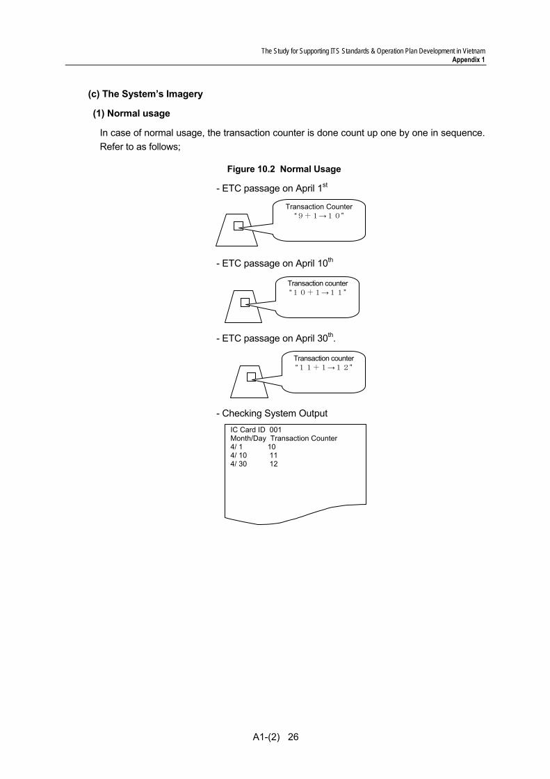
(c) The System’s Imagery
(1) Normal usage
In case of normal usage, the transaction counter is done count up one by one in sequence. Refer to as follows;
Figure 10.2 Normal Usage
- ETC passage on April 1st
- ETC passage on April 10th
- ETC passage on April 30th.
- Checking System Output
IC Card ID 001 Month/Day Transaction Counter 4/ 1 10 4/ 10 11 4/ 30 12
Transaction Counter “9+1→10”
Transaction counter “10+1→11”
Transaction counter “11+1→12”

The Study for Supporting ITS Standards & Operation Plan Development in Vietnam Appendix 1
A1-(2) 27
(2) Wrong usage (in case of counterfeited IC-card)
Figure 10.3 Wrong Usage
- Counterfeiting the card which passed ETC on April 1st
- ETC passage using only the original card on April 10th
- ETC passage using only the counterfeited card 1 on April 30th
- Checking System Output
The same value is founded. The existence of counterfeited card: Since the IC cards have the same ID, under different transactions, it is impossible for the values in transaction counter to secure the consistency.
IC Card ID 001 Month/Day Transaction Counter 4/ 1 10 4/ 10 11 4/ 30 11
Original card Transaction Counter “11”
(Not used on the day)
Transaction Counter “10”
(Not used on the day)
Counterfeited Card 1 Transaction Counter “10 +1→11”
Counterfeited Card 2
Original card Transaction Counter “10 +1 → 11”
Transaction Counter “10”
(Not used on the day)
Transaction Counter “10”
(Not used on the day)
Counterfeited Card 1
Counterfeited Card 2
Original card
Transaction Counter “10”
Counterfeited Card 1 Counterfeited Card 2
The Study for Supporting ITS Standards & Operation Plan Development in Vietnam Appendix 1
A1-(2) 28
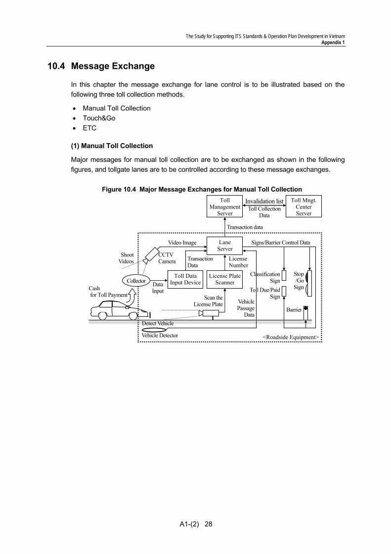
10.4 Message Exchange
In this chapter the message exchange for lane control is to be illustrated based on the following three toll collection methods.
• Manual Toll Collection • Touch&Go • ETC
(1) Manual Toll Collection
Major messages for manual toll collection are to be exchanged as shown in the following figures, and tollgate lanes are to be controlled according to these message exchanges.
Figure 10.4 Major Message Exchanges for Manual Toll Collection
DataInput
Toll DataInput Device
LaneServer
TransactionData
License PlateScanner
Scan theLicense Plate
LicenseNumber
VehiclePassage
DataDetect Vehicle
CCTVCamera
Shoot Videos
Video Image
Transaction data
Toll Collection Data
Vehicle Detector
Barrier
Stop /Go
Sign
Classification Sign
Toll Due/Paid Sign
<Roadside Equipment>
Signs/Barrier Control Data
Collector Cash for Toll Payment
Toll Mngt. Center Server
TollManagement
Server
Invalidation list
The Study for Supporting ITS Standards & Operation Plan Development in Vietnam Appendix 1
A1-(2) 29
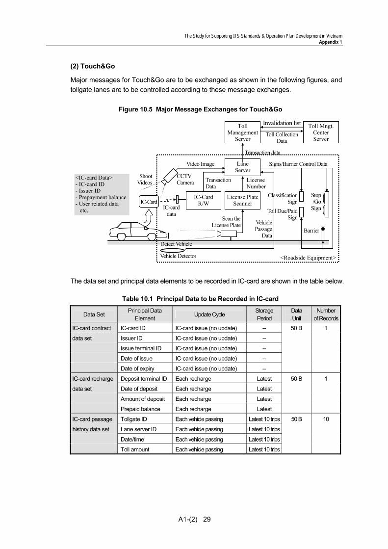
(2) Touch&Go
Major messages for Touch&Go are to be exchanged as shown in the following figures, and tollgate lanes are to be controlled according to these message exchanges.
Figure 10.5 Major Message Exchanges for Touch&Go
The data set and principal data elements to be recorded in IC-card are shown in the table below.
Table 10.1 Principal Data to be Recorded in IC-card
Data Set Principal Data
Element Update Cycle
Storage Period
Data Unit
Numberof Records
IC-card contract IC-card ID IC-card issue (no update) -- 50 B 1
data set Issuer ID IC-card issue (no update) --
Issue terminal ID IC-card issue (no update) --
Date of issue IC-card issue (no update) --
Date of expiry IC-card issue (no update) --
IC-card recharge Deposit terminal ID Each recharge Latest 50 B 1
data set Date of deposit Each recharge Latest
Amount of deposit Each recharge Latest
Prepaid balance Each recharge Latest
IC-card passage Tollgate ID Each vehicle passing Latest 10 trips 50 B 10
history data set Lane server ID Each vehicle passing Latest 10 trips
Date/time Each vehicle passing Latest 10 trips
Toll amount Each vehicle passing Latest 10 trips
<IC-card Data> - IC-card ID - Issuer ID - Prepayment balance - User related data etc.
IC-CardR/W
LaneServer
TransactionData
License PlateScanner
Scan theLicense Plate
LicenseNumber
VehiclePassage
DataDetect Vehicle
CCTVCamera
Shoot Videos
Video Image
Vehicle Detector
Barrier
Stop/Go
Sign
Classification Sign
Toll Due/Paid Sign
<Roadside Equipment>
Signs/Barrier Control Data
IC-carddata
IC-Card
Transaction data
Toll Collection Data
Toll Mngt.Center Server
TollManagement
Server
Invalidation list
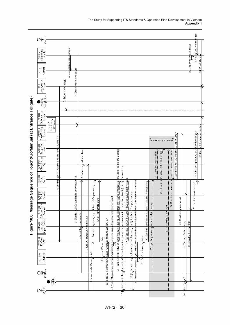
Figu
re 1
0.6
Mes
sage
Seq
uenc
e of
Tou
ch&
Go/
Man
ual (
at E
ntra
nce
Tollg
ate)
A1-(2) 30
The Study for Supporting ITS Standards & Operation Plan Development in VietnamAppendix 1
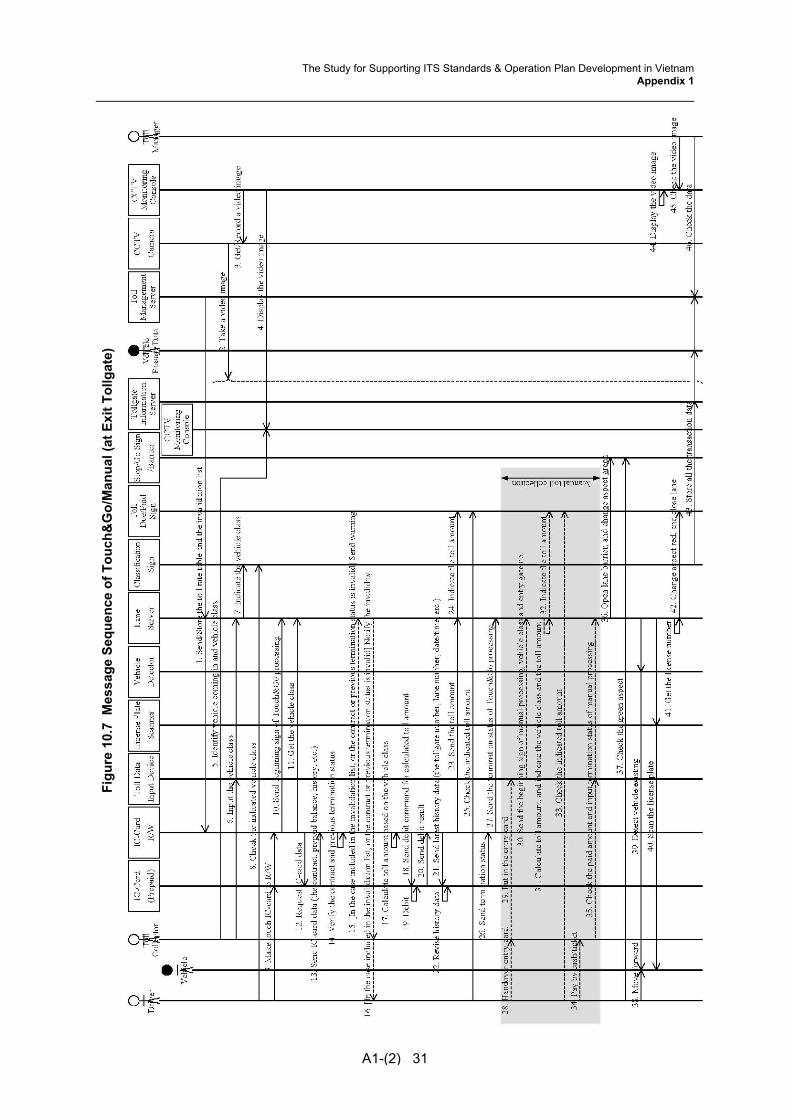
Figu
re 1
0.7
Mes
sage
Seq
uenc
e of
Tou
ch&
Go/
Man
ual (
at E
xit T
ollg
ate)
A1-(2) 31
The Study for Supporting ITS Standards & Operation Plan Development in VietnamAppendix 1

The Study for Supporting ITS Standards & Operation Plan Development in Vietnam Appendix 1
A1-(2) 32
(3) ETC
Major messages for ETC are to be exchanged as shown in the following figures, and tollgate lanes are to be controlled according to these message exchanges.
Figure 10.8 Major Message Exchanges for ETC
The data set and principal data elements to be recorded in OBU are shown in the table below.
Table 10.2 Principal Data ETC to be Recorded in OBU
Data Set Principal Data
Element Update Cycle
Storage Period
Data Unit
Numberof Records
OBU registration OBU ID OBU registration (no update) -- 50 B 1
data set Date of issue OBU registration (no update) --
License number OBU registration (no update) --
Vehicle class OBU registration (no update) --
OBU passage Tollgate ID Each vehicle passing Latest 50 B 1
data set Lane server ID Each vehicle passing Latest
Date/time Each vehicle passing Latest
Toll amount Each vehicle passing Latest
RoadsideAntenna ETC
Controller
LaneServer
OBU data andIC-card data
TransactionData
IC-Card
License PlateScanner
Scan theLicense Plate
OBU
<IC-card D in OBU
C-card ID - Issuer ID - Prepayment balance - User related data
t
<OBU Data> - OBU ID - License number - Vehicle class - User eelated data etc.
LicenseNumber
Vehicle Passage
Data Detect Vehicle
CCTVCamera
Shoot Videos
Video Image
Vehicle Detector
Barrier
Stop/Go
Sign
Classification Sign
Toll Due/Paid Sign
<Roadside Equipment>
Signs/Barrier Control Data
Transaction data
Toll Collection Data
Toll Mngt.Center Server
TollManagement
Server
Invalidation list
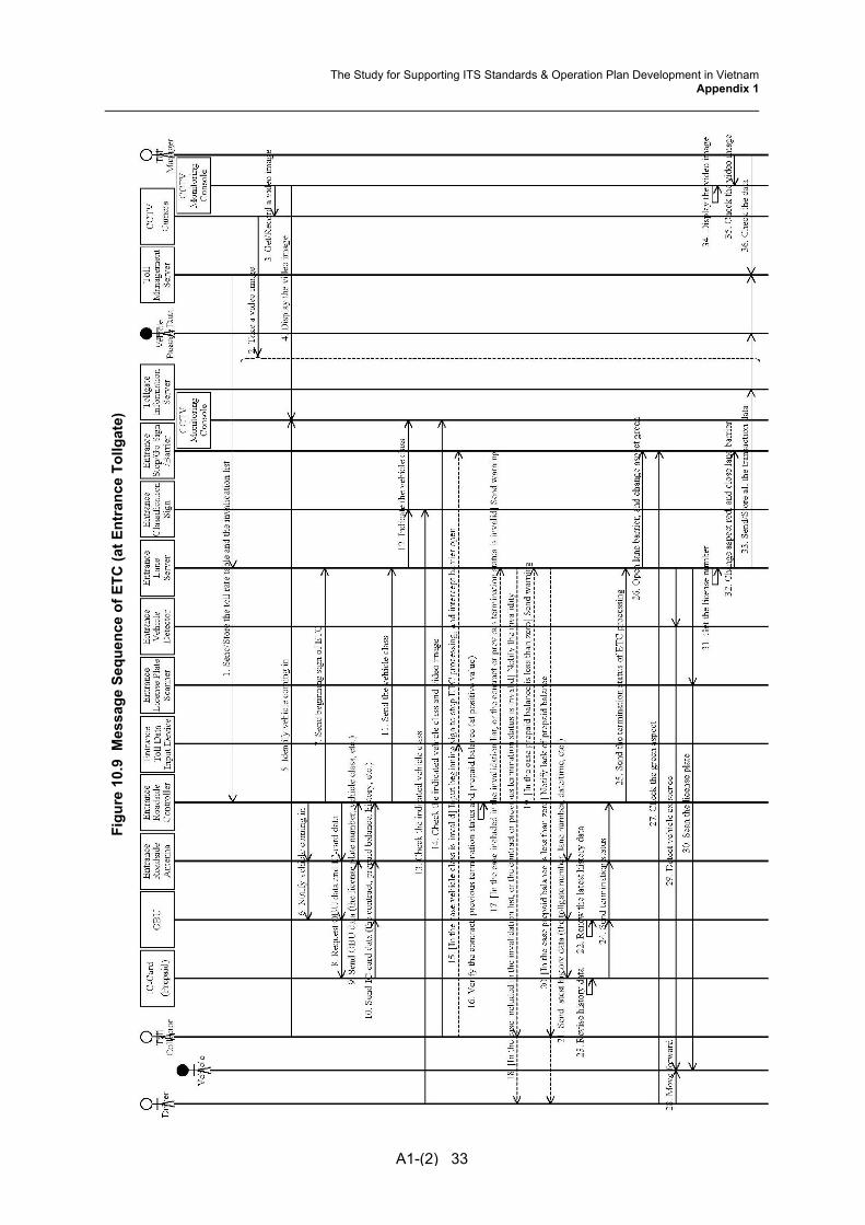
Figu
re 1
0.9
Mes
sage
Seq
uenc
e of
ETC
(at E
ntra
nce
Tollg
ate)
A1-(2) 33
The Study for Supporting ITS Standards & Operation Plan Development in VietnamAppendix 1
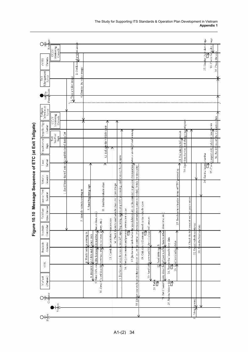
Figu
re 1
0.10
Mes
sage
Seq
uenc
e of
ETC
(at E
xit T
ollg
ate)
A1-(2) 34
The Study for Supporting ITS Standards & Operation Plan Development in VietnamAppendix 1
The Study for Supporting ITS Standards & Operation Plan Development in Vietnam Appendix 1
A1-(2) 35
10.5 Transmission Design The video data is transferred via Mpeg4-Partt and all other signals and data are transferred via Internet and communication Protocol is transferred via TCP/IP.
The system is constructed after disclosing the availability of trouble, necessary information, procedure and Interface software according to the self-diagnosis by center side equipment on sensors installed at roadside.
Further concepts and methodologies are to be referred to the Draft Communication System Plan.

The Study for Supporting ITS Standards & Operation Plan Development in Vietnam Appendix 1
A1-(2) 36
11. Road-to-Vehicle Communication
11.1 Outlines This functional package allows the road operators to exchange data for toll collection and other services on the expressways by using radio communication between antennas installed at roadside and on-board units installed in the vehicles.
11.2 System Architecture
Figure 11.1 System Architecture for Road-to-Vehicle Communication
Toll Booth Roadside
: Switching Hub & Media Converter : Media Converter : SDH Node
: Equipment Package : Location : Detailed Device
: Fibre Optic Cable : Copper Cable
Broken Lines: Outside of This Functional Package
License Plate Scanner
RoadsideAntenna
Lane Server
RoadsideController
In-Vehicle
OBU
: DSRC
The Study for Supporting ITS Standards & Operation Plan Development in Vietnam Appendix 1
A1-(2) 37
11.3 Functional Design 1) Summary of Road-Vehicle Information and Communication
There are many kind technologies for toll collection. The technology is not to know for Automatic Vehicle Identification only; it is for the system of handle the money of citizen. The technology shall be capable of collection strictly safety, quickly and accurately. So, we have to consider the countermeasures for that purpose such as encryption of transaction data, invalidation list, transaction counter and so on. These technique needs enough capacity of communication between Roadside to Vehicle and enough processing power of chip on OBU and IC-Card (include RFID).
Therefore, study team is of the opinion that “DSRC” is adequate for ETC in Vietnam. The advantage is in terms of security and capacity of communication.
2) About each method of ETC technologies
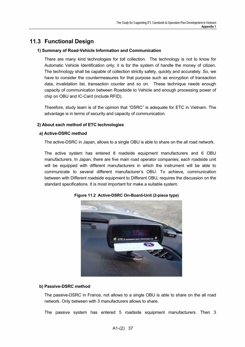
a) Active-DSRC method
The active-DSRC in Japan, allows to a single OBU is able to share on the all road network.
The active system has entered 8 roadside equipment manufacturers and 6 OBU manufacturers. In Japan, there are five main road operator companies; each roadside unit will be equipped with different manufacturers in which the instrument will be able to communicate to several different manufacturer’s OBU. To achieve, communication between with Different roadside equipment to Different OBU, requires the discussion on the standard specifications. It is most important for make a suitable system.
Figure 11.2 Active-DSRC On-Board-Unit (2-piece type)
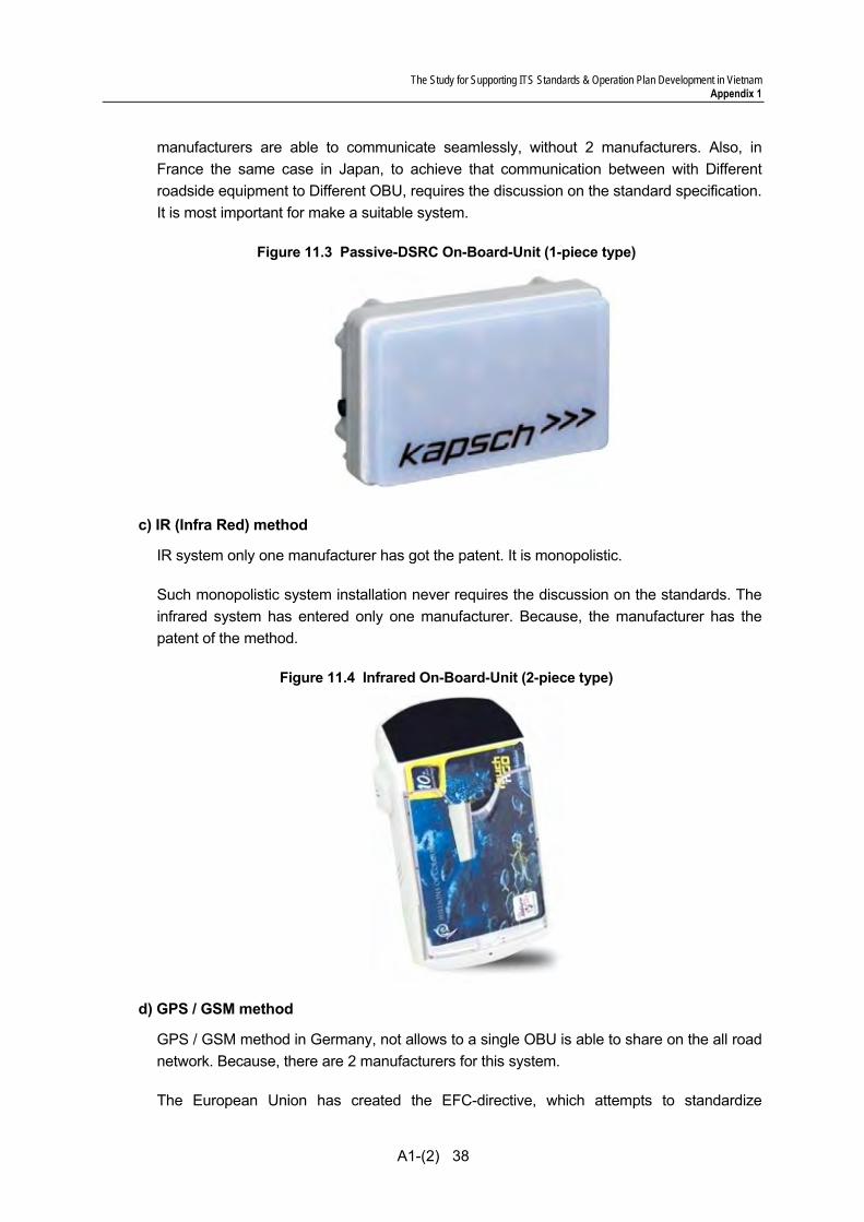
b) Passive-DSRC method
The passive-DSRC in France, not allows to a single OBU is able to share on the all road network. Only between with 3 manufacturers allows to share.
The passive system has entered 5 roadside equipment manufacturers. Then 3
The Study for Supporting ITS Standards & Operation Plan Development in Vietnam Appendix 1
A1-(2) 38
manufacturers are able to communicate seamlessly, without 2 manufacturers. Also, in France the same case in Japan, to achieve that communication between with Different roadside equipment to Different OBU, requires the discussion on the standard specification. It is most important for make a suitable system.
Figure 11.3 Passive-DSRC On-Board-Unit (1-piece type)
c) IR (Infra Red) method
IR system only one manufacturer has got the patent. It is monopolistic.
Such monopolistic system installation never requires the discussion on the standards. The infrared system has entered only one manufacturer. Because, the manufacturer has the patent of the method.
Figure 11.4 Infrared On-Board-Unit (2-piece type)
d) GPS / GSM method
GPS / GSM method in Germany, not allows to a single OBU is able to share on the all road network. Because, there are 2 manufacturers for this system.
The European Union has created the EFC-directive, which attempts to standardize
The Study for Supporting ITS Standards & Operation Plan Development in Vietnam Appendix 1
A1-(2) 39
European toll collection systems. Systems deployed after 2007 must support at least one of the following technologies: satellite positioning, mobile communications using the GSM-GPRS standard or 5.8 GHz microwave technology. In toll-collection, a few facilities cover a very wide area, making fixed toll gates impractical. The most notable of these is a truck tolling system in Germany. This system uses Global Positioning System location information to identify when a vehicle is located on a tolled Autobahn. However, implementation of this system turned out to be far lengthier and more costly than expected.
Figure 11.5 GPS / GSM On-Board-Unit
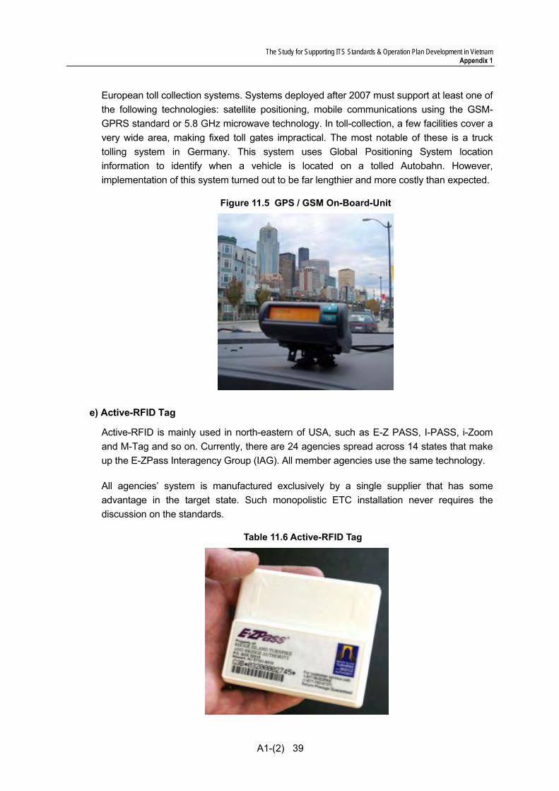
e) Active-RFID Tag
Active-RFID is mainly used in north-eastern of USA, such as E-Z PASS, I-PASS, i-Zoom and M-Tag and so on. Currently, there are 24 agencies spread across 14 states that make up the E-ZPass Interagency Group (IAG). All member agencies use the same technology.
All agencies’ system is manufactured exclusively by a single supplier that has some advantage in the target state. Such monopolistic ETC installation never requires the discussion on the standards.
Table 11.6 Active-RFID Tag
The Study for Supporting ITS Standards & Operation Plan Development in Vietnam Appendix 1
A1-(2) 40
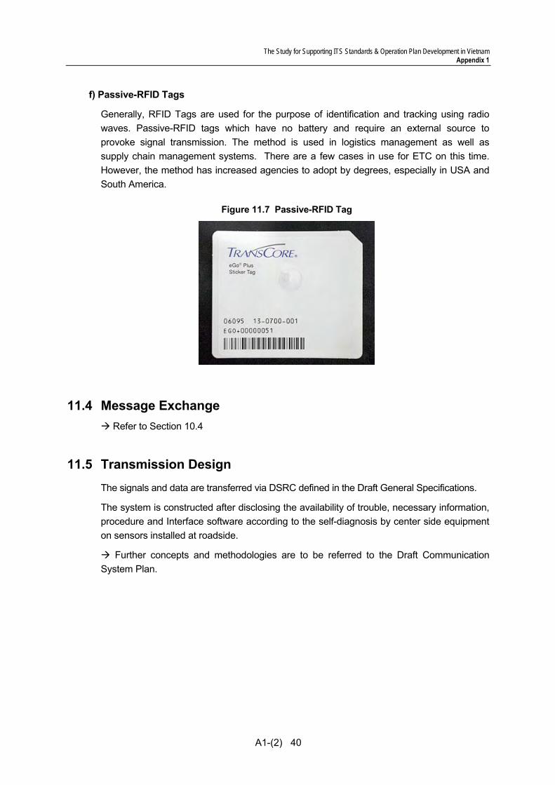
f) Passive-RFID Tags
Generally, RFID Tags are used for the purpose of identification and tracking using radio waves. Passive-RFID tags which have no battery and require an external source to provoke signal transmission. The method is used in logistics management as well as supply chain management systems. There are a few cases in use for ETC on this time. However, the method has increased agencies to adopt by degrees, especially in USA and South America.
Figure 11.7 Passive-RFID Tag
11.4 Message Exchange
Refer to Section 10.4
11.5 Transmission Design The signals and data are transferred via DSRC defined in the Draft General Specifications.
The system is constructed after disclosing the availability of trouble, necessary information, procedure and Interface software according to the self-diagnosis by center side equipment on sensors installed at roadside.
Further concepts and methodologies are to be referred to the Draft Communication System Plan.
The Study for Supporting ITS Standards & Operation Plan Development in Vietnam Appendix 1
A1-(2) 41
12. IC-Card Recording
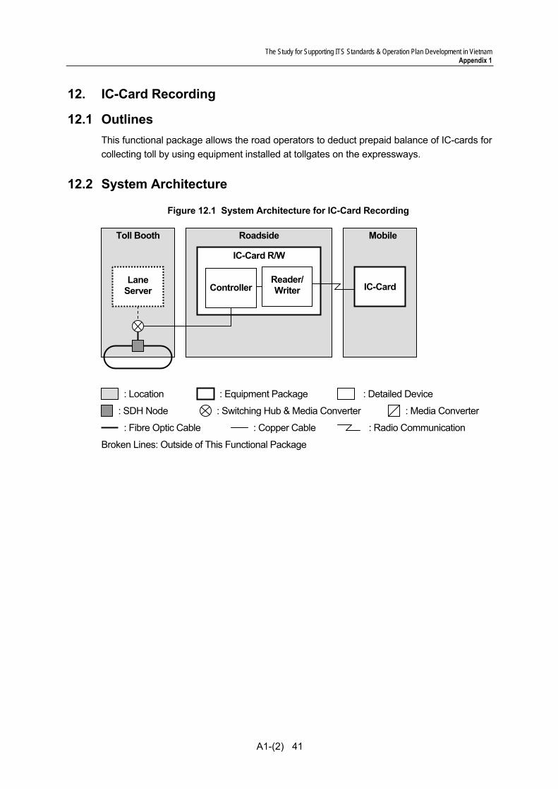
12.1 Outlines This functional package allows the road operators to deduct prepaid balance of IC-cards for collecting toll by using equipment installed at tollgates on the expressways.
12.2 System Architecture
Figure 12.1 System Architecture for IC-Card Recording
Toll Booth Roadside
: Switching Hub & Media Converter : Media Converter : SDH Node
: Equipment Package : Location : Detailed Device
: Fibre Optic Cable : Copper Cable
Broken Lines: Outside of This Functional Package
IC-Card R/W
Reader/ Writer
Lane Server
Mobile
IC-Card
: Radio Communication
Controller
The Study for Supporting ITS Standards & Operation Plan Development in Vietnam Appendix 1
A1-(2) 42
12.3 Functional Design
1) Summary for various contactless IC-cards
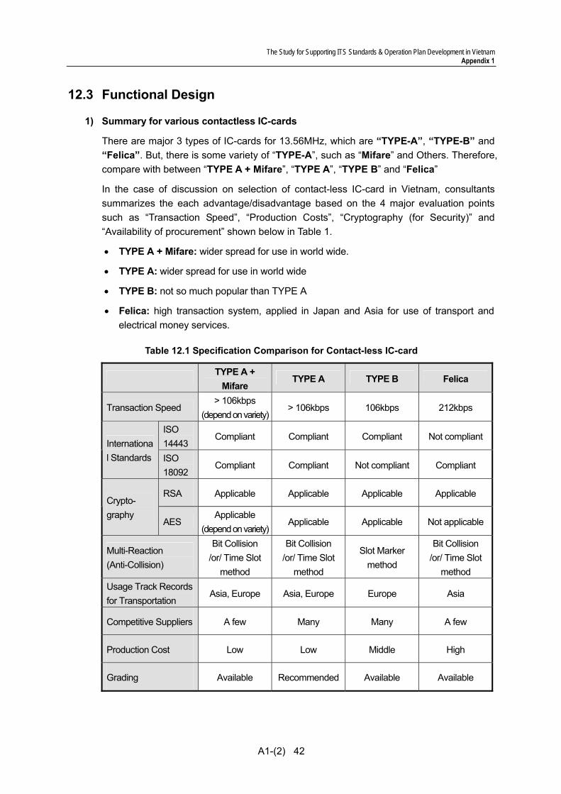
There are major 3 types of IC-cards for 13.56MHz, which are “TYPE-A”, “TYPE-B” and “Felica”. But, there is some variety of “TYPE-A”, such as “Mifare” and Others. Therefore, compare with between “TYPE A + Mifare”, “TYPE A”, “TYPE B” and “Felica”
In the case of discussion on selection of contact-less IC-card in Vietnam, consultants summarizes the each advantage/disadvantage based on the 4 major evaluation points such as “Transaction Speed”, “Production Costs”, “Cryptography (for Security)” and “Availability of procurement” shown below in Table 1.
• TYPE A + Mifare: wider spread for use in world wide.
• TYPE A: wider spread for use in world wide
• TYPE B: not so much popular than TYPE A
• Felica: high transaction system, applied in Japan and Asia for use of transport and electrical money services.
Table 12.1 Specification Comparison for Contact-less IC-card
TYPE A +
Mifare TYPE A TYPE B Felica
Transaction Speed > 106kbps
(depend on variety)> 106kbps 106kbps 212kbps
ISO 14443
Compliant Compliant Compliant Not compliant International Standards ISO
18092 Compliant Compliant Not compliant Compliant
RSA Applicable Applicable Applicable Applicable Crypto-graphy
AES Applicable
(depend on variety)Applicable Applicable Not applicable
Multi-Reaction (Anti-Collision)
Bit Collision /or/ Time Slot
method
Bit Collision /or/ Time Slot
method
Slot Marker method
Bit Collision /or/ Time Slot
method Usage Track Records for Transportation
Asia, Europe Asia, Europe Europe Asia
Competitive Suppliers A few Many Many A few
Production Cost Low Low Middle High
Grading Available Recommended Available Available

The Study for Supporting ITS Standards & Operation Plan Development in Vietnam Appendix 1
A1-(2) 43
2) Evaluation Point of Contactless IC-cards
(1) Transaction Speed
“Felica” has advantage than others. “Felica” has about twice of its transaction speeds than other system.
(2) Production Cost
“TYPE-A” has advantage than others. In general, “TYPE-A (especially Mifare Classic)” can be made in lowest cost than others, next is “TYPE-B”. “Felica” is high costs than others.
“TYPE-A” has several types such as Mifare Classic, Mifare Plus, Mifare Desfire and so on.
However, there is reported that “Mifare Classic” has been faced the security problem recently. Because, it shall be not capable of using secure cryptography algorithm.
(3) Cryptography (for security)
There are many cryptography algorithm. “RSA”, “AES” and “T-DES” are now used worldwide comparatively.
AES has advantage than others. T-DES(2keys or 3keys) is selectable, however shall be consideration of the risk aversion on other way.
• AES: In cryptography, AES (the Advanced Encryption Standard) is a symmetric-key encryption standard adopted by the U.S. government. Respectively, the AES ciphers have been analyzed extensively and are now used worldwide. AES have no advantage over RSA, however the processing speed is higher than RSA.
• RSA: In cryptography, RSA is an algorithm for public-key cryptography. RSA is widely used in electronic commerce protocols, and is believed to be secure given sufficiently long keys and the use of up-to-date implementations.
• T-DES(2keys or 3keys): In cryptography, T-DES(Triple DES) is the common name for the Triple Data Encryption Algorithm block cipher, which applies the Data Encryption Standard cipher algorithm three times to each data block. Because of the availability of increasing computational power, the key size of the original DES cipher was becoming subject to brute force attacks; T-DES was designed to provide a relatively simple method of increasing the key size of DES to protect against such attacks, without designing a completely new block cipher algorithm. However, there is reported T-DES(1key) has been faced the security problem recently.
(4) Availability of procurement
“TYPE-A + Mifare” and “Felica” are supplied by a few suppliers. The detail specification of the type is not disclosed by the developed supplier.
In future, the IC-Card is produced in Vietnam. In case of the future, the IC-chip (RFID) should be provided by many suppliers for reduce the cost of procurement.
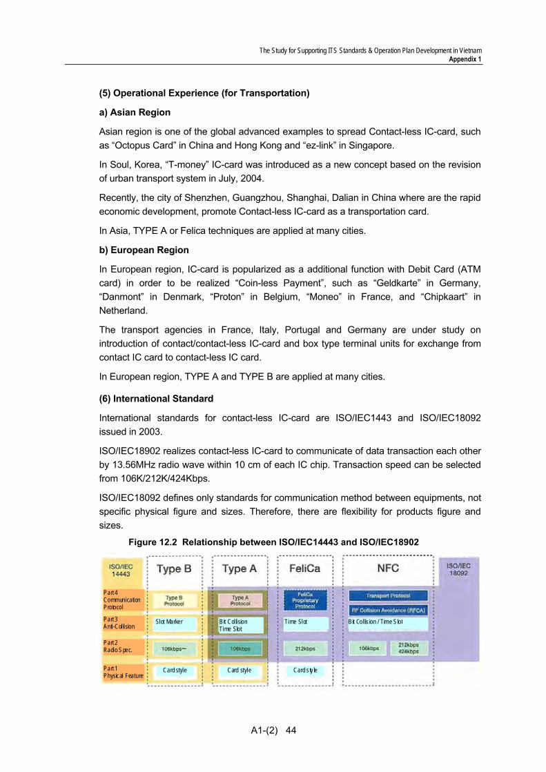
The Study for Supporting ITS Standards & Operation Plan Development in Vietnam Appendix 1
A1-(2) 44
(5) Operational Experience (for Transportation)
a) Asian Region
Asian region is one of the global advanced examples to spread Contact-less IC-card, such as “Octopus Card” in China and Hong Kong and “ez-link” in Singapore.
In Soul, Korea, “T-money” IC-card was introduced as a new concept based on the revision of urban transport system in July, 2004.
Recently, the city of Shenzhen, Guangzhou, Shanghai, Dalian in China where are the rapid economic development, promote Contact-less IC-card as a transportation card.
In Asia, TYPE A or Felica techniques are applied at many cities.
b) European Region
In European region, IC-card is popularized as a additional function with Debit Card (ATM card) in order to be realized “Coin-less Payment”, such as “Geldkarte” in Germany, “Danmont” in Denmark, “Proton” in Belgium, “Moneo” in France, and “Chipkaart” in Netherland.
The transport agencies in France, Italy, Portugal and Germany are under study on introduction of contact/contact-less IC-card and box type terminal units for exchange from contact IC card to contact-less IC card.
In European region, TYPE A and TYPE B are applied at many cities.
(6) International Standard
International standards for contact-less IC-card are ISO/IEC1443 and ISO/IEC18092 issued in 2003.
ISO/IEC18902 realizes contact-less IC-card to communicate of data transaction each other by 13.56MHz radio wave within 10 cm of each IC chip. Transaction speed can be selected from 106K/212K/424Kbps.
ISO/IEC18092 defines only standards for communication method between equipments, not specific physical figure and sizes. Therefore, there are flexibility for products figure and sizes.
Figure 12.2 Relationship between ISO/IEC14443 and ISO/IEC18902
Part 4 Communication Protocol
Part 3 Anti-Collision
Part 2 Radio Spec.
Part 1 Physical Feature
Slot Marker Bit CollisionTime Slot
Time Slot Bit Collis ion / Time Slot
Card style Card style Card s ty le

The Study for Supporting ITS Standards & Operation Plan Development in Vietnam Appendix 1
A1-(2) 45
(10) Multi-Reaction (Anti-Collision)
Anti-collision method is meant how to process IC-cards when two or more IC-cards exist in the area of read/write system (R/W). There are 3 major different methods.
• Time Slot method: Each IC-card creates the random number based on R/W's request, and then IC-card will response in accordance with created number. R/W can identify the each IC-card based on their response timing.
• Bit Collision method: R/W can identify the each card based on their response with their unique series of “Bit” such as “1” or “0” until R/W recognizes without any duplication of their bits.
• Slot Marker method: R/W requests random number to IC-card to identify each card.
The following table shows their characteristics.
Table12.2 Characteristics of Anti-Collision Methods
Anti-Collision Method Characteristics
Time Slot method Only one request from R/W at initiation stage is needed, therefore, it is less number of transactions.
Bit Collision method It takes time because R/W requires judging the all of Bit series.
Slot Marker method It takes time because R/W requests all of cards.
Table12.3 Specification Comparison for Contact-less IC-card
TYPE A TYPE B Felica
Transaction Speed in initiate stage
+ 106kbps
+ 106kbps
++ 212kbps
International Standard
++ ISO/IEC14443
& ISO/IEC18092
+ ISO/IEC14443
+ ISO/IEC18092
Production Cost ++
Relatively modest cost +
Relatively costly +
Relatively costly
Encryption method for Security
+ Original (Mifare classic)
++ RSA, T-DES, AES (Mifare Desfire)
++ RSA, T-DES, AES
(depend on the variants)
++ T-DES, AES
(depend on the variants)
Operational Experiences
++ Asia, Europe
++ Asia, Europe
+ Asia
Communication Range
+ 10 ㎝
+ 10 ㎝
+ 10 ㎝
Encoding method +
Modified Miller +
NRZ-L +
Manchester
Multi-Reaction (Anti-Collision)
++ Bit Collision
/or/ Time Slot method
+ Slot Marker method
++ Bit Collision
/or/ Time Slot method

The Study for Supporting ITS Standards & Operation Plan Development in Vietnam Appendix 1
A1-(2) 46
3) Human Machine Interface
(1) IC-Card Name of Card holder and IC card ID are also printed on the IC card. Additionally, for security reason, it is advisable to add card holder’s signature and hologram, etc.
Figure 12.3 IC-Card image sample
(2) IC-Card R/W (Reader / Writer) IC-Card Reader/Writer shall be capable of notifying normal/abnormal and insufficient prepaid balance on “IC Card” to the users.
The notice is given visually such as LED light, Display. (refer Figure 2)
Figure 12.4 IC-Card R/W HMI
(In Malysia) (In Japan: test installation)
IC module Contactless type
IC-Card ID Printing
Barcode
Information of Issuing Agency
Facial portrait
Magnetic stripeOption
Option
Signature panelIn card holder's original handwriting
Hologram
Thumbprint by laser
<Front side>
<Back side>
Issuing Agency Name Issuing Agency Address
* This figure is just for image sample. There is difference due to various restrictions actually.
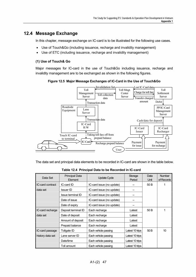
The Study for Supporting ITS Standards & Operation Plan Development in Vietnam Appendix 1
A1-(2) 47
12.4 Message Exchange In this chapter, message exchange on IC-card is to be illustrated for the following use cases.
• Use of Touch&Go (including issuance, recharge and invalidity management) • Use of ETC (including issuance, recharge and invalidity management)
(1) Use of Touch& Go
Major messages for IC-card in the use of Touch&Go including issuance, recharge and invalidity management are to be exchanged as shown in the following figures.
Figure 12.5 Major Message Exchanges of IC-Card in the Use of Touch&Go
The data set and principal data elements to be recorded in IC-card are shown in the table below.
Table 12.4 Principal Data to be Recorded in IC-card
Data Set Principal Data
Element Update Cycle
Storage Period
Data Unit
Numberof Records
IC-card contract IC-card ID IC-card issue (no update) -- 50 B 1
data set Issuer ID IC-card issue (no update) --
Issue terminal ID IC-card issue (no update) --
Date of issue IC-card issue (no update) --
Date of expiry IC-card issue (no update) --
IC-card recharge Deposit terminal ID Each recharge Latest 50 B 1
data set Date of deposit Each recharge Latest
Amount of deposit Each recharge Latest
Prepaid balance Each recharge Latest
IC-card passage Tollgate ID Each vehicle passing Latest 10 trips 50 B 10
history data set Lane server ID Each vehicle passing Latest 10 trips
Date/time Each vehicle passing Latest 10 trips
Toll amount Each vehicle passing Latest 10 trips
Taking toll fare off from prepaid balance
Recharge prepaid balanceIC-Card
LaneServer
Roadside Equipment
Transaction data
Toll collectiondata
IC-CardR/W
Touch IC-card to terminal
Charge for toll fare
Transfer charged amount
User
Paymentfor recharge
Payment for issue
IC-Card Issuer
IC-CardRecharger
Lost IC-Card data Invalidation list
Transaction data
TollManagement
Server
TollSettlement
Server
Toll Mngt.Center Server
Cash/data for deposit
PP/IC-CardManagement
Server
Debit

The Study for Supporting ITS Standards & Operation Plan Development in Vietnam Appendix 1
A1-(2) 48
The equipment components shall be capable of recording the data on Contactless IC-Card, such as ID number, usage history information (date, entry and exit IC, the collected toll amount) and prepaid balance information. The stored data are shown in Table 3.
Table 12.5 Data Set and Principal Data Elements in “IC-Card”
Data Set Principal Data Element Update Cycle IC-card IC-card ID IC-Card issue contract Issuer ID IC-Card issue data set Issue terminal ID IC-Card issue Date of issue IC-Card issue Date of expiry IC-Card issue IC-Card Deposit terminal ID Each recharge Recharge Date of deposit Each recharge Data set Amount of deposit Each recharge Prepaid balance Each recharge IC-Card Tollgate ID Each vehicle passing Passage Lane Server ID Each vehicle passing History Date / Time Each vehicle passing Data set Toll amount Each vehicle passing Transaction Termination sign * Each vehicle passing Data set Permanently voided code ** Each vehicle passing Transaction counter *** Each vehicle passing
Note,*: It is Remarque that the IC-card is completed the transaction on Entry or Exit, **: It is remark for the IC-card is voided or not, ***: It is for against illegal duplication of IC-card.
In order to verify the balance and usage history of the IC-card upon the request of Card holder, the distribution of reader which is capable of reading information linked with the computer by option is also considered. The IC-card is capable of storing up to 10 data of usage history information so that card holder can verify the usage history afterward. The data element as shown in the table below.
Table 12.6 Data Set and Principal Data Elements for Toll history data
Data Set Principal Data Element Toll Date/time (1) collection Entry Inter Change ID (1) history Exit Inter Change ID (1) data Toll amount (1) Date/time (2) Entry Interchange ID (2) Exit Interchange ID (2) Toll amount (2) : Date/time (10) Entry Inter Change ID (10) Exit Inter Change ID (10) Toll amount (10)
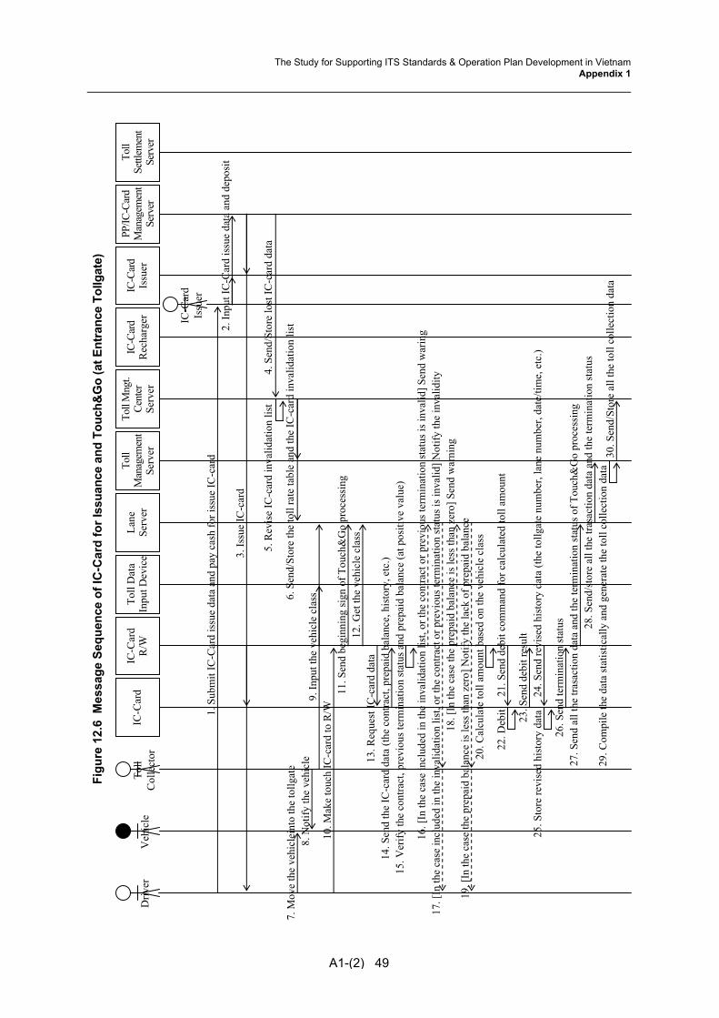
Figu
re 1
2.6
Mes
sage
Seq
uenc
e of
IC-C
ard
for I
ssua
nce
and
Touc
h&G
o (a
t Ent
ranc
e To
llgat
e)
A1-(2) 49
Toll
Dat
aIn
put D
evic
eTo
ll M
ngt.
Cent
er
Serv
er
Lane
Serv
er
IC-C
ard
R/W
D
river
14. S
end
the
IC-c
ard
data
(the
con
tract
, pre
paid
bal
ance
, his
tory
, etc
.)
7. M
ove
the
vehi
clei
nto
the
tollg
ate
8. N
otify
the
vehi
cle
11. S
end
begi
nnin
g si
gn o
f Tou
ch&
Go
proc
essi
ng
13. R
eque
st IC
-car
d da
ta
30. S
end/
Stor
e al
l the
toll
colle
ctio
n da
ta29
. Com
pile
the
data
stat
istic
ally
and
gen
erat
e th
e to
ll co
llect
ion
data
22. D
ebit
IC-C
ard
Issu
er
IC-C
ard
Rec
harg
erTo
ll M
anag
emen
t Se
rver
1. S
ubm
it IC
-Car
d is
sue
data
and
pay
cas
h fo
r iss
ue IC
-car
d 2.
Inpu
t IC
-Car
d is
sue
data
and
dep
osit
3. Is
sue
IC-c
ard
Toll
Col
lect
or
IC-C
ard
Veh
icle
23. S
end
debi
t res
ult
26. S
end
term
inat
ion
stat
us
24. S
end
revi
sed
hist
ory
data
(the
tollg
ate
num
ber,
lane
num
ber,
date
/tim
e, e
tc.)
25. S
tore
revi
sed
hist
ory
data
28. S
end/
stor
e al
l the
tras
actio
n da
ta a
nd th
e te
rmin
atio
n st
atus
9. In
put t
he v
ehic
le c
lass
10. M
ake
touc
h IC
-car
d to
R/W
27. S
end
all t
he tr
asac
tion
data
and
the
term
inat
ion
stat
us o
f Tou
ch&
Go
proc
essi
ng
12. G
et th
e ve
hicl
e cl
ass
21. S
end
debi
t com
man
d fo
r cal
cula
ted
toll
amou
nt
20. C
alcu
late
toll
amou
nt b
ased
on
the
vehi
cle
clas
s
16. [
In th
e ca
se in
clud
ed in
the
inva
lidat
ion
list,
or th
e co
ntra
ct o
r pre
viou
s ter
min
atio
n st
atus
is in
valid
] Sen
d w
arin
g17
. [In
the
case
incl
uded
in th
e in
valid
atio
n lis
t, or
the
cont
ract
or p
revi
ous t
erm
inat
ion
stat
us is
inva
lid] N
otify
the
inva
lidity
18. [
In th
e ca
se th
e pr
epai
d ba
lanc
e is
less
than
zer
o] S
end
war
ning
19
. [In
the
case
the
prep
aid
bala
nce
is le
ss th
an z
ero]
Not
ify th
e la
ck o
f pre
paid
bal
ance
15. V
erify
the
cont
ract
, pre
viou
s ter
min
atio
n st
atus
and
pre
paid
bal
ance
(at p
ositi
ve v
alue
)
6. S
end/
Stor
e th
e to
ll ra
te ta
ble
and
the
IC-c
ard
inva
lidat
ion
list
4. S
end/
Stor
e lo
st IC
-car
d da
ta
5. R
evis
e IC
-car
d in
valid
atio
n lis
t
Toll
Settl
emen
tSe
rver
PP/IC
-Car
dM
anag
emen
tSe
rver
IC-C
ard
Issu
er
The Study for Supporting ITS Standards & Operation Plan Development in VietnamAppendix 1

Figu
re 1
2.7
Mes
sage
Seq
uenc
e of
IC-C
ard
for T
ouch
&G
o (a
t Exi
t Tol
lgat
e) a
nd R
echa
rge
Toll
Dat
aIn
put D
evic
eTo
ll M
ngt.
Cent
er
Serv
er
Lane
Serv
er
IC-C
ard
R/W
D
river
13. S
end
the
IC-c
ard
data
(the
con
tract
, pre
paid
bal
ance
, his
tory
, etc
.)
6. M
ove
the
vehi
clei
nto
the
tollg
ate
7. N
otify
the
vehi
cle
10. S
end
begi
nnin
g si
gn o
f Tou
ch&
Go
proc
essi
ng
12. R
eque
st IC
-car
d da
ta
27. S
end/
Stor
e al
l the
toll
colle
ctio
n da
ta26
. Com
pile
the
data
stat
istic
ally
and
gen
erat
e th
e to
ll co
llect
ion
data
29. C
harg
e fo
r tol
l far
e
31. T
rans
fer c
harg
ed a
mou
nt
28. C
alcu
late
tota
l am
ount
of t
oll f
are
19. D
ebit
IC-C
ard
Issu
er
IC-C
ard
Rec
harg
erTo
ll M
anag
emen
t Se
rver
To
ll C
olle
ctor
IC
-Car
dV
ehic
le
20. S
end
debi
t res
ult
23. S
end
term
inat
ion
stat
us21
. Sen
d re
vise
d hi
stor
y da
ta (t
he to
llgat
e nu
mbe
r, la
ne n
umbe
r, da
te/ti
me,
etc
.)22
. Sto
re re
vise
d hi
stor
y da
ta
25. S
end/
stor
e al
l the
tras
actio
n da
ta a
nd th
e te
rmin
atio
n st
atus
8. In
put t
he v
ehic
le c
lass
9. M
ake
touc
h IC
-car
d to
R/W
24. S
end
all t
he tr
asac
tion
data
and
the
term
inat
ion
stat
us o
f Tou
ch&
Go
proc
essi
ng
11. G
et th
e ve
hicl
e cl
ass
14. V
erify
the
cont
ract
and
pre
viou
s ter
min
atio
n st
atus
18. S
end
debi
t com
man
d fo
r cal
cula
ted
toll
amou
nt
17. C
alcu
late
toll
amou
nt b
ased
on
the
vehi
cle
clas
s
32. P
ut IC
-car
d in
and
pay
cas
h fo
r rec
harg
e33
. Dep
osit
34. R
echa
rge
the
bala
nce
of IC
-car
d
15. [
In th
e ca
se th
e co
ntra
ct o
r pre
viou
s ter
min
atio
n st
atus
is in
valid
] Sen
d w
arin
g16
. [In
the
case
the
cont
ract
or p
revi
ous t
erm
inat
ion
stat
us is
inva
lid] N
otify
the
inva
lidity
5. S
end/
Stor
e th
e to
ll ra
te ta
ble
and
the
IC-c
ard
inva
lidat
ion
list
3. S
end
lost
IC-c
ard
data
4. R
evis
e IC
-car
d in
valid
atio
n lis
t
1. S
end
lost
IC-c
ard
notif
icat
ion
2. In
put l
ost I
C-c
ard
data
Toll
Settl
emen
tSe
rver
PP/IC
-Car
dM
anag
emen
tSe
rver
IC-C
ard
Issu
er
30. D
ebit
A1-(2) 50
The Study for Supporting ITS Standards & Operation Plan Development in VietnamAppendix 1
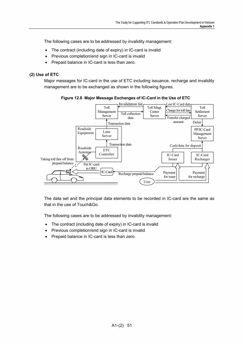
The Study for Supporting ITS Standards & Operation Plan Development in Vietnam Appendix 1
A1-(2) 51
The following cases are to be addressed by invalidity management:
• The contract (including date of expiry) in IC-card is invalid • Previous completion/end sign in IC-card is invalid • Prepaid balance in IC-card is less than zero.
(2) Use of ETC Major messages for IC-card in the use of ETC including issuance, recharge and invalidity management are to be exchanged as shown in the following figures.
Figure 12.8 Major Message Exchanges of IC-Card in the Use of ETC
The data set and the principal data elements to be recorded in IC-card are the same as that in the use of Touch&Go.
The following cases are to be addressed by invalidity management:
• The contract (including date of expiry) in IC-card is invalid • Previous completion/end sign in IC-card is invalid • Prepaid balance in IC-card is less than zero.
Roadside Antenna ETC
Controller
LaneServer
Put IC-card in OBU
Roadside Equipment
IC-Card
Transaction data
Taking toll fare off fromprepaid balance
TollManagement
Server Toll collectiondata
Toll Mngt.Center Server
Transaction data
Invalidation listCharge for toll fare
Transfer charged amount
User
Paymentfor recharge
Payment for issue
IC-Card Issuer
IC-CardRecharger
Lost IC-Card data Toll
Settlement Server
Cash/data for deposit
PP/IC-CardManagement
Server
Debit
Recharge prepaid balance
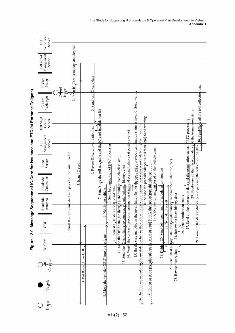
Figu
re 1
2.9
Mes
sage
Seq
uenc
e of
IC-C
ard
for I
ssua
nce
and
ETC
(at E
ntra
nce
Tollg
ate)
A1-(2) 52
Roa
dsid
eC
ontro
ller
Toll
Mng
t.Ce
nter
Se
rver
Lane
Serv
er
OB
UR
oads
ide
Ant
enna
Driv
er
13. S
end
the
IC-c
ard
data
(the
con
tract
, pre
paid
bal
ance
, his
tory
, etc
.)14
. Ver
ify th
e co
ntra
ct, p
revi
ous t
erm
inat
ion
stat
us a
nd p
repa
id b
alan
ce (a
t pos
itive
val
ue)
20. S
end
debi
t com
man
d fo
r cal
cula
ted
toll
amou
nt
4. P
ut IC
-car
d in
to O
BU
8. M
ove
the
vehi
cle
(OB
U) i
nto
the
tollg
ate
9. N
otify
the
vehi
cle
10. S
end
begi
nnin
g si
gn o
f ETC
pro
cess
ing
11. R
eque
st O
BU
dat
a an
d IC
-car
d da
ta12
. Sen
d th
e O
BU
dat
a (th
e lic
ense
pla
te n
umbe
r, ve
hicl
e cl
ass,
etc.
)
30. S
end/
Stor
e al
l the
toll
colle
ctio
n da
ta29
. Com
pile
the
data
stat
istic
ally
and
gen
erat
e th
e to
ll co
llect
ion
data
19. C
alcu
late
toll
amou
nt b
ased
on
the
vehi
cle
clas
s 21
. Deb
it
IC-C
ard
Issu
er
IC-C
ard
Rec
harg
erTo
ll M
anag
emen
tSe
rver
1. S
ubm
it IC
-Car
d is
sue
data
and
pay
cas
h fo
r iss
ue IC
-car
d 2.
Inpu
t IC
-Car
d is
sue
data
and
dep
osit
3. Is
sue
IC-c
ard
Toll
Col
lect
or
IC-C
ard
Veh
icle
22. S
end
debi
t res
ult
24. R
enew
the
late
st h
isto
ry d
ata
26. S
end
term
inat
ion
stat
us
23. S
end
late
st h
isto
ry d
ata
(the
tollg
ate
num
ber,
lane
num
ber,
date
/tim
e, e
tc.)
25. R
evis
e hi
stor
y da
ta
27. S
end
all t
he tr
ansa
ctio
n da
ta a
nd th
e te
rmin
atio
n st
atus
of E
TC p
roce
ssin
g28
. Sen
d/st
ore
all t
he tr
asac
tion
data
and
the
term
inat
ion
stat
us
17. [
In th
e ca
se th
e pr
epai
d ba
lanc
e is
less
than
zer
o] S
end
war
ning
18. [
In th
e ca
se th
e pr
epai
d ba
lanc
e is
less
than
zer
o] N
otify
the
lack
of p
repa
id b
alan
ce
7. S
end/
Stor
e th
e to
ll ra
te ta
ble
and
the
IC-c
ard
inva
lidat
ion
list 5. S
end
lost
IC-c
ard
data
6.
Rev
ise
IC-c
ard
inva
lidat
ion
list
15. [
In th
e ca
se in
clud
ed in
the
inva
lidat
ion
list,
or th
e co
ntra
ct o
r pre
viou
s ter
min
atio
n st
atus
is in
valid
] Sen
d w
arin
g16
. [In
the
case
incl
uded
in th
e in
valid
atio
n lis
t, or
the
cont
ract
or p
revi
ous t
erm
inat
ion
stat
us is
inva
lid] N
otify
the
inva
lidity
Toll
Settl
emen
t Se
rver
PP/IC
-Car
dM
anag
emen
tSe
rver
IC-C
ard
Issu
er
The Study for Supporting ITS Standards & Operation Plan Development in VietnamAppendix 1

A1-(2) 53
Figu
re 1
2.10
Mes
sage
Seq
uenc
e of
IC-C
ard
for E
TC (a
t Exi
t Tol
lgat
e) a
nd R
echa
rge
Roa
dsid
eC
ontro
ller
Toll
Mng
t.Ce
nter
Se
rver
Lane
Serv
er
OB
UR
oads
ide
Ant
enna
Driv
er
11. S
end
the
IC-c
ard
data
(the
con
tract
, pre
paid
bal
ance
, his
tory
, etc
.)12
. Ver
ify th
e co
ntra
ct a
nd p
revi
ous t
erm
inat
ion
stat
us
16. S
end
debi
t com
man
d fo
r cal
cula
ted
toll
amou
nt
6. M
ove
the
vehi
cle
(OB
U) i
nto
the
tollg
ate
7. N
otify
the
vehi
cle
8. S
end
begi
nnin
g si
gn o
f ETC
pro
cess
ing
9. R
eque
st O
BU
dat
a an
d IC
-car
d da
ta10
. Sen
d th
e O
BU
dat
a (th
e lic
ense
pla
te n
umbe
r, ve
hicl
e cl
ass,
etc.
)
26. S
end/
Stor
e al
l the
toll
colle
ctio
n da
ta25
. Com
pile
the
data
stat
istic
ally
and
gen
erat
e th
e to
ll co
llect
ion
data
15. C
alcu
late
toll
amou
nt b
ased
on
the
vehi
cle
clas
s
28. C
harg
e fo
r tol
l far
e
30. T
rans
fer c
harg
ed a
mou
nt
27. C
alcu
late
tota
l am
ount
of t
oll f
are
17. D
ebit
IC-C
ard
Issu
er
IC-C
ard
Rec
harg
erTo
ll M
anag
emen
tSe
rver
Toll
Settl
emen
t Se
rver
To
ll C
olle
ctor
IC
-Car
d V
ehic
le
18. S
end
debi
t res
ult
20. R
enew
the
late
sthi
stor
y da
ta
22. S
end
term
inat
ion
stat
us
19. S
end
late
st h
isto
ry d
ata
(the
tollg
ate
num
ber,
lane
num
ber,
date
/tim
e, e
tc.)
19. R
evis
e hi
stor
y da
ta
23.S
end
all t
he tr
asac
tion
data
and
the
term
inat
ion
stat
us o
f ETC
pro
cess
ing
24. S
end/
stor
e al
l the
tras
actio
n da
ta a
nd th
e te
rmin
atio
n st
atus
31. P
ut IC
-car
d in
and
pay
cas
h fo
r rec
harg
e32
. De p
osit
33. R
echa
rge
the
bala
nce
of IC
-car
d
5. S
end/
Stor
e th
e to
ll ra
te ta
ble
and
the
IC-c
ard
inva
lidat
ion
list 3. S
end
lost
IC-c
ard
data
4. R
evis
e IC
-car
d in
valid
atio
n lis
t
13. [
In th
e ca
se in
clud
ed in
the
inva
lidat
ion
list,
or th
e co
ntra
ct o
r pre
viou
s ter
min
atio
n st
atus
is in
valid
] Sen
d w
arin
g14
. [In
the
case
incl
uded
in th
e in
valid
atio
n lis
t, or
the
cont
ract
or p
revi
ous t
erm
inat
ion
stat
us is
inva
lid] N
otify
the
inva
lidity
1. S
end
lost
IC-c
ard
notif
icat
ion
2. In
put l
ost I
C-c
ard
data
PP/IC
-Car
dM
anag
emen
tSe
rver
IC-C
ard
Issu
er
29. D
ebit
The Study for Supporting ITS Standards & Operation Plan Development in VietnamAppendix 1

The Study for Supporting ITS Standards & Operation Plan Development in Vietnam Appendix 1
A1-(2) 54
12.5 Transmission Design The signals and data are transferred via communication protocol for IC-card defined in the Draft General Specifications.
The system is constructed after disclosing the availability of trouble, necessary information, procedure and Interface software according to the self-diagnosis by center side equipment on sensors installed at roadside.
Further concepts and methodologies are to be referred to the Draft Communication System Plan.
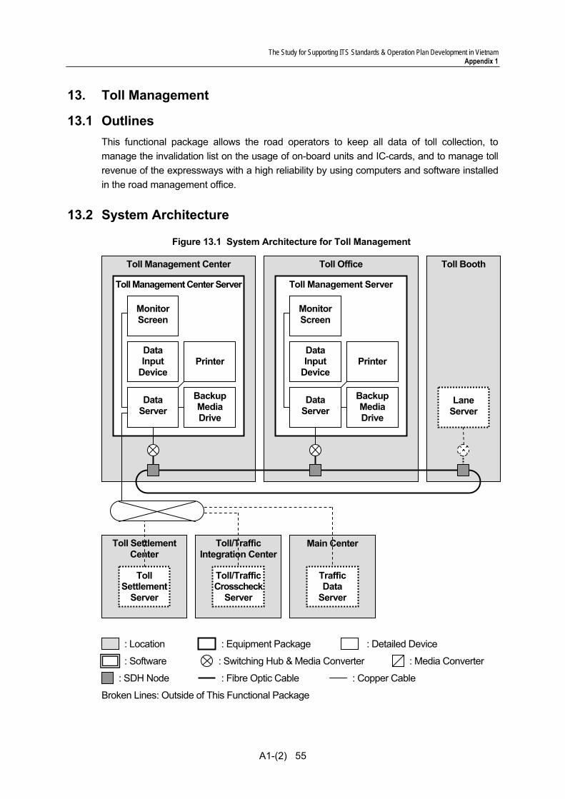
The Study for Supporting ITS Standards & Operation Plan Development in Vietnam Appendix 1
A1-(2) 55
13. Toll Management
13.1 Outlines This functional package allows the road operators to keep all data of toll collection, to manage the invalidation list on the usage of on-board units and IC-cards, and to manage toll revenue of the expressways with a high reliability by using computers and software installed in the road management office.
13.2 System Architecture
Figure 13.1 System Architecture for Toll Management
Toll Settlement Center
Toll Booth Toll Office Toll Management Center
Toll Management Center Server
Monitor Screen
Printer
Backup Media Drive
Data Server
: Switching Hub & Media Converter : Media Converter
: SDH Node
: Equipment Package : Location : Detailed Device
: Fibre Optic Cable : Copper Cable
Broken Lines: Outside of This Functional Package
: Software
Data Input
Device
Toll Management Server
Monitor Screen
Printer
Backup Media Drive
Data Server
Data Input
Device
Lane Server
Toll/Traffic Integration Center
Toll/TrafficCrosscheck
Server
Toll Settlement
Server
Main Center
Traffic Data
Server

The Study for Supporting ITS Standards & Operation Plan Development in Vietnam Appendix 1
A1-(2) 56
13.3 Functional Design 1) Mainly function of this package
In this functional package shall be capable of generation the toll collection data and checking whether the difference between the actual number of vehicle which pass through the tollgate and collect fees. In addition, generate the billing data of prepaid card users and claim to the bank which the card issuer.
There is need to generate billing data for each bank, if the bank is multiple that the card issuer. This package is one of the most important systems for each road management company.
2) The method for secure toll collection
a) Checking using “Invalidation list”
Invalidation list is for checking the card which shall be invalidated such as stolen and so on. If the invalidated card is used on toll, the fee is not collected from bank. Therefore, we have to consider the card shall not be capable of using for toll collection. The process is shown in the figure below.
Figure 13.2 Process of using Invalidation list
IC-Card
Card Issuer(as BANK)
[In case of IC-Card is stolen]Claim to Card issuer stop to use the IC-Card[In case of IC-card holder is bankrupt]Inform to Card issuer the information
Toll SettlementCenter
Card Issuer inform to send the IC-Card ID which has to stop to use.
Toll Settlement Center generate “Invalidation List”.IC-Card, expire date are shown on “Invalidation List”
Toll Settlement
Server
Toll Management
Center
Toll Management Center Server
Toll Office
Toll Management
Server
Toll gate
Lane Server
Invalidation List
“Invalidation List” is stored to Toll Management Center Server and transmit to Toll Management Server
“Invalidation List” is stored to Toll Management Server and transmit to Lane Server at Lane side
Invalidation List
IC-CardIC-Card
When toll collection; Check IC-Card’s ID, it is on “Invalidation List” or not.If the ID is on “Invalidation List”, the system inform attention to Toll Collector. Then, Lane Server makes stop the vehicle and claim to Toll Office.
Invalidation List
Invalidation List
The Study for Supporting ITS Standards & Operation Plan Development in Vietnam Appendix 1
A1-(2) 57
b) Checking using “License number”
The toll fee amount of each car is depended on type of vehicle according to degree of Ministry of Finance standard; the vehicle class is recorded in OBU when set up OBU. If the OBU is moved to from car to different type of car, the ETC system charge the incorrect fee. For secure toll collection, we have to compare between the vehicle class and actual vehicle type using License number.
Therefore, Licence number shall be recorded in OBU and Vehicle Identification system (such as License Plate scanner) shall be installed on toll lane. Then the toll management system shall be check that the Licence number is the same or not due to comparison of between Licence number (by OBU) in Transaction data set and License number (by scan) in Toll collection data set; refer to Table 13.1 Data Set and Principal Data Elements for Toll Management.
c) Checking using “Termination sign”
In sometime, the communication between Roadside and Vehicle is not termination properly due to affected by the disorder outside and the being overheard. The system shall not be capable of settlement completely the error.
Therefore, Transaction data set include “Termination sign” which is for checking the communication is terminated properly or not. If the sign is not recorded, the meaning is the communication is not terminated properly. Refer to Table 13.1 Data Set and Principal Data Elements for Toll Management.
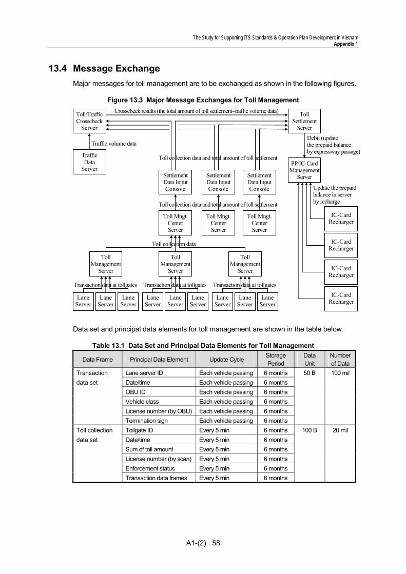
The Study for Supporting ITS Standards & Operation Plan Development in Vietnam Appendix 1
A1-(2) 58
13.4 Message Exchange Major messages for toll management are to be exchanged as shown in the following figures.
Figure 13.3 Major Message Exchanges for Toll Management
Data set and principal data elements for toll management are shown in the table below.
Table 13.1 Data Set and Principal Data Elements for Toll Management
Data Frame Principal Data Element Update Cycle Storage Period
Data Unit
Numberof Data
Transaction Lane server ID Each vehicle passing 6 months 50 B 100 mildata set Date/time Each vehicle passing 6 months OBU ID Each vehicle passing 6 months Vehicle class Each vehicle passing 6 months License number (by OBU) Each vehicle passing 6 months Termination sign Each vehicle passing 6 months Toll collection Tollgate ID Every 5 min 6 months 100 B 20 mil data set Date/time Every 5 min 6 months Sum of toll amount Every 5 min 6 months License number (by scan) Every 5 min 6 months Enforcement status Every 5 min 6 months Transaction data frames Every 5 min 6 months
Toll Management
Server
Toll Mngt.Center Server
SettlementData InputConsole
Toll/Traffic Crosscheck
Server
Traffic Data
Server PP/IC-Card
Management Server
TollManagement
Server
TollManagement
Server
Toll Mngt.Center Server
Toll Mngt.Center Server
Toll Settlement
Server
SettlementData InputConsole
SettlementData InputConsole
IC-CardRecharger
IC-CardRecharger
IC-CardRecharger
Lane Server
Lane Server
Lane Server
Lane Server
LaneServer
LaneServer
LaneServer
LaneServer
LaneServer
IC-CardRecharger
Update the prepaidbalance in server by recharge
Transaction data at tollgates
Toll collection data
Transaction data at tollgates Transaction data at tollgates
Toll collection data and total amount of toll settlement
Toll collection data and total amount of toll settlement
Traffic volume data
Crosscheck results (the total amount of toll settlement–traffic volume data)
Debit (updatethe prepaid balance by expressway passage)
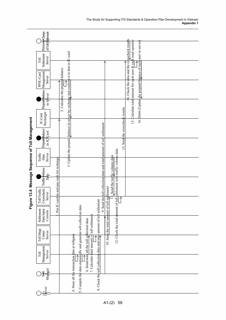
Figu
re 1
3.4
Mes
sage
Seq
uenc
e of
Tol
l Man
agem
ent
Toll
Mng
t. Ce
nter
Se
rver
IC-C
ard
Rec
harg
erTo
llSe
ttlem
ent
Serv
er
Toll
Man
ager
PP/IC
-Car
dM
anag
emen
tSe
rver
D
river
A1-(2) 59
Settl
emen
tD
ata I
nput
Con
sole
Toll/
Traf
ficCr
ossc
heck
Serv
er
Traf
ficD
ata
Serv
er
Traff
ic Vo
lume
Dat
a Pr
epaid
Bala
nce
in IC
-Car
dPr
epaid
Bala
nce
in S
erve
r Pe
rson i
n Cha
rge
of To
ll Sett
lemen
t
1. P
ut IC
-car
d in
and
pay
cas
h fo
r rec
harg
e2.
Cal
cula
te th
e pr
epai
d ba
lanc
e
3. U
pdat
e th
e pr
epai
d ba
lanc
e in
serv
er b
y re
char
ge a
nd c
onfo
rm it
to th
at in
IC-c
ard
5. C
ompi
le th
e da
ta st
atis
tical
ly a
nd g
ener
ate
toll
colle
ctio
n da
ta
7. C
alcu
late
tota
l am
ount
of t
oll s
ettle
men
t
8. C
heck
the
toll
colle
ctio
n da
ta a
nd to
tal a
mou
nt o
f tol
l set
tlem
ent
9. S
end
the
toll
colle
ctio
n da
ta a
nd to
tal a
mou
nt o
f tol
l set
tlem
ent
10. S
end
the
tota
l am
ount
of t
oll s
ettle
men
t11
. Sen
d th
e tra
ffic
vol
ume
data
12. C
heck
the
tota
l am
ount
of t
oll s
ettle
men
t with
traf
fic v
olum
e da
ta 13. S
end
the
cros
sche
ck re
sults
14. C
heck
the
data
and
the
cros
sche
ck re
sults
15
. Cal
cula
te to
tal a
mou
nt fo
r eac
h us
er &
eac
h ro
ad o
pera
tor
16. D
ebit
(Upd
ate
the
prep
aid
bala
nce
of e
ach
user
in se
rver
)
Toll
Man
agem
ent
Serv
er
4. S
tore
all
the
trans
actio
n da
ta a
t tol
lgat
es
6. S
end/
stor
e al
l the
toll
colle
ctio
n da
ta
The Study for Supporting ITS Standards & Operation Plan Development in VietnamAppendix 1
The Study for Supporting ITS Standards & Operation Plan Development in Vietnam Appendix 1
A1-(2) 60
13.5 Transmission Design All the signals and data are transferred via Internet and communication Protocol is transferred via TCP/IP.
The system is constructed after disclosing the availability of trouble, necessary information, procedure and Interface software according to the self-diagnosis by center side equipment on sensors installed at roadside.
Further concepts and methodologies are to be referred to the Draft Communication System Plan.

The Study for Supporting ITS Standards & Operation Plan Development in Vietnam Appendix 1
A1-(2) 61
14. OBU Management
14.1 Outlines This functional package allows to register on-board units by using equipment installed in OBU issue offices, and allows to generate/manage the registration list and the invalidation list of on-board units by using computers and software installed in the OBU registration center.
14.2 System Architecture
Figure 14.1 System Architecture for OBU Management
OBU Issue OfficeOBU Management
Center
: Switching Hub & Media Converter : Media Converter : SDH Node
: Equipment Package : Location : Detailed Device
: Fibre Optic Cable : Copper Cable
Broken Lines: Outside of This Functional Package
In-Vehicle
OBU
: DSRC
OBU RegistrationTerminal
OBU Management
Server
Toll ManagementCenter
Toll Mgmt. Center Server
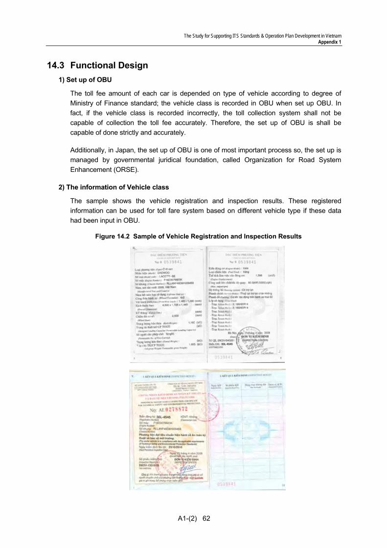
The Study for Supporting ITS Standards & Operation Plan Development in Vietnam Appendix 1
A1-(2) 62
14.3 Functional Design 1) Set up of OBU
The toll fee amount of each car is depended on type of vehicle according to degree of Ministry of Finance standard; the vehicle class is recorded in OBU when set up OBU. In fact, if the vehicle class is recorded incorrectly, the toll collection system shall not be capable of collection the toll fee accurately. Therefore, the set up of OBU is shall be capable of done strictly and accurately.
Additionally, in Japan, the set up of OBU is one of most important process so, the set up is managed by governmental juridical foundation, called Organization for Road System Enhancement (ORSE).
2) The information of Vehicle class
The sample shows the vehicle registration and inspection results. These registered information can be used for toll fare system based on different vehicle type if these data had been input in OBU.
Figure 14.2 Sample of Vehicle Registration and Inspection Results

The Study for Supporting ITS Standards & Operation Plan Development in Vietnam Appendix 1
A1-(2) 63
3) The way of set up and re-set up
There is some method for the set up. For example; a) connect cable, b) using the same as DSRC antenna, c) using IC-Card. The characteristic of each method as follows;
a) Using cable
Cost: Cheapest (OBU shall be equipped the interface of cable connection) Re-set up: Inconvenient (user should go to OBU Issue Office and bring the OBU)
Figure 14.3 Set up using Cable
b) Using DSRC antenna
Cost: Expensive (DSRC antenna shall be installed on each OBU Issue Office) Re-set up: Convenient (can be set up at OBU Issue Office and Tollgate)
Figure 14.4 Set up OBU using DSRC antenna
c) Using IC-Card
Cost: Cheaper (OBU shall be 2 piece type and IC-Card R/W shall be installed on each OBU Issue Office)
Re-set up: Convenient (can be set up at OBU Issue Office and Tollgate)
Figure 14.5 Set up OBU using IC-Card
OBU Issue Office In-Vehicle
OBU
OBU Registration Terminal
Using Cable
OBU Issue Office In-Vehicle
OBU
OBU Registration Terminal
DSRCAntenna
OBU Issue Office In-Vehicle
OBU
OBU Registration Terminal
IC-CardR/W IC-
Card
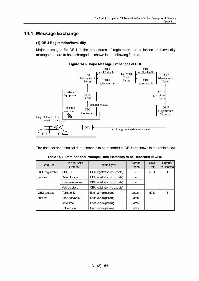
The Study for Supporting ITS Standards & Operation Plan Development in Vietnam Appendix 1
A1-(2) 64
14.4 Message Exchange
(1) OBU Registration/Invalidity
Major messages for OBU in the procedures of registration, toll collection and invalidity management are to be exchanged as shown in the following figures.
Figure 14.6 Major Message Exchanges of OBU
The data set and principal data elements to be recorded in OBU are shown in the table below.
Table 14.1 Data Set and Principal Data Elements to be Recorded in OBU
Data Set Principal Data
Element Update Cycle
Storage Period
Data Unit
Numberof Records
OBU registration OBU ID OBU registration (no update) -- 50 B 1
data set Date of issue OBU registration (no update) --
License number OBU registration (no update) --
Vehicle class OBU registration (no update) --
OBU passage Tollgate ID Each vehicle passing Latest 50 B 1
data set Lane server ID Each vehicle passing Latest
Date/time Each vehicle passing Latest
Toll amount Each vehicle passing Latest
Roadside Antenna ETC
Controller
LaneServer
Roadside Equipment
OBU
Transaction data
OBU registration data installation
Taking toll fare off fromprepaid balance
OBUregistration
data
OBURegistration
Terminal
TollManagement
Server
OBUManagement
Server OBU registration list
Toll Mngt.Center Server
OBU invalidation list
OBUinvalidation list
OBUregistration list
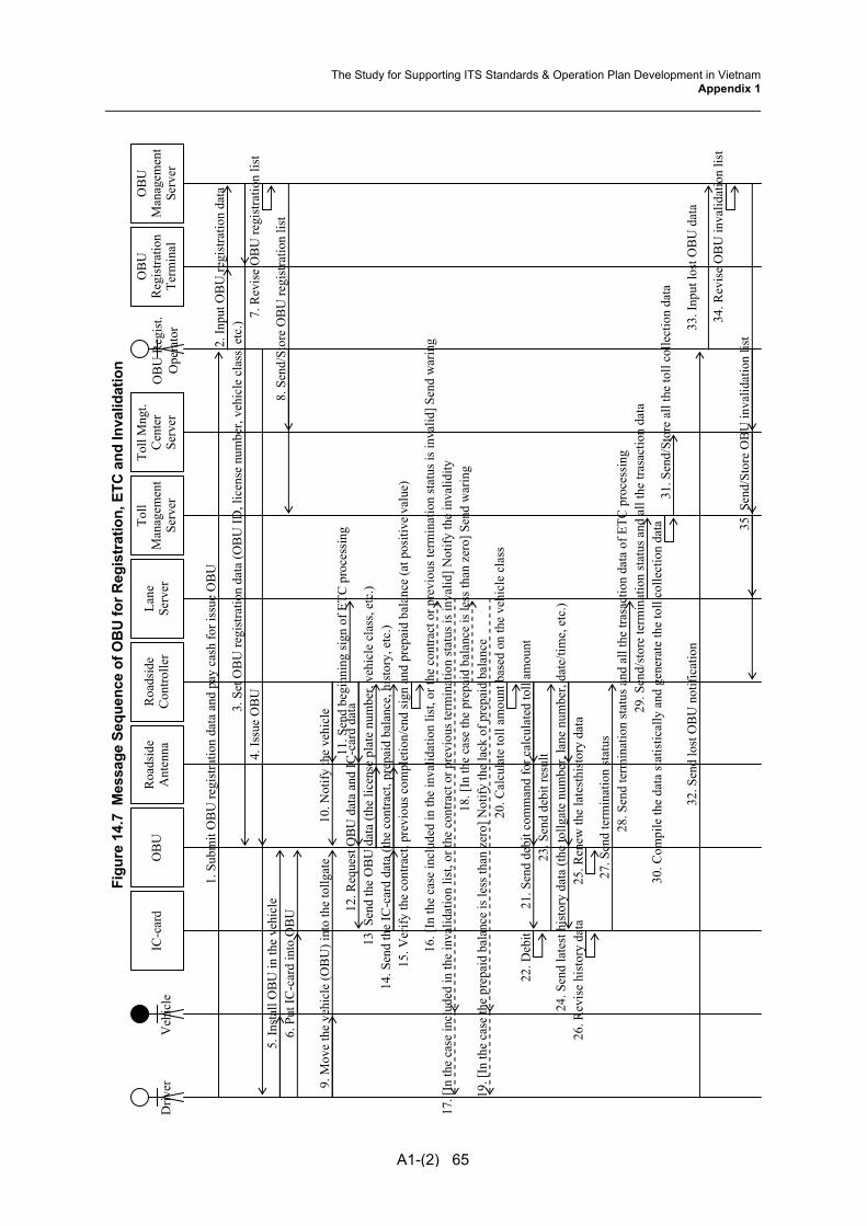
Figu
re 1
4.7
Mes
sage
Seq
uenc
e of
OB
U fo
r Reg
istr
atio
n, E
TC a
nd In
valid
atio
n
A1-(2) 65
Roa
dsid
eC
ontro
ller
Lane
Serv
er
OB
UR
oads
ide
Ant
enna
D
river
V
ehic
le
6. P
ut IC
-car
d in
to O
BU
3. S
et O
BU
regi
stra
tion
data
(OB
U ID
, lic
ense
num
ber,
vehi
cle
clas
s, et
c.)
5. In
stal
l OB
U in
the
vehi
cle
Toll
Man
agem
ent
Serv
er
Toll
Mng
t.C
ente
r Se
rver
OB
UR
egis
tratio
nTe
rmin
al
OB
UM
anag
emen
t Se
rver
IC
-car
d O
BU
Reg
ist.
Ope
rato
r
2. In
put O
BU
regi
stra
tion
data
4. Is
sue
OB
U7.
Rev
ise
OB
U re
gist
ratio
n lis
t
8. S
end/
Stor
e O
BU
regi
stra
tion
list
35. S
end/
Stor
e O
BU
inva
lidat
ion
list
9. M
ove
the
vehi
cle
(OB
U) i
nto
the
tollg
ate
10. N
otify
the
vehi
cle
11. S
end
begi
nnin
g si
gn o
f ETC
pro
cess
ing
1. S
ubm
it O
BU
regi
stra
tion
data
and
pay
cas
h fo
r iss
ue O
BU
14. S
end
the
IC-c
ard
data
(the
con
tract
, pre
paid
bal
ance
, his
tory
, etc
.)15
. Ver
ify th
e co
ntra
ct, p
revi
ous c
ompl
etio
n/en
d si
gn a
nd p
repa
id b
alan
ce (a
t pos
itive
val
ue)
21. S
end
debi
t com
man
d fo
r cal
cula
ted
toll
amou
nt
12. R
eque
st O
BU
dat
a an
d IC
-car
d da
ta13
. Sen
d th
e O
BU
dat
a (th
e lic
ense
pla
te n
umbe
r, ve
hicl
e cl
ass,
etc.
)
20. C
alcu
late
toll
amou
nt b
ased
on
the
vehi
cle
clas
s 22
. Deb
it 23
. Sen
d de
bit r
esul
t
25. R
enew
the
late
sthi
stor
y da
ta
27. S
end
term
inat
ion
stat
us
24. S
end
late
st h
isto
ry d
ata
(the
tollg
ate
num
ber,
lane
num
ber,
date
/tim
e, e
tc.)
26. R
evis
e hi
stor
y da
ta
28. S
end
term
inat
ion
stat
us a
nd a
ll th
e tra
sact
ion
data
of E
TC p
roce
ssin
g29
. Sen
d/st
ore
term
inat
ion
stat
us a
nd a
ll th
e tra
sact
ion
data
18. [
In th
e ca
se th
e pr
epai
d ba
lanc
e is
less
than
zer
o] S
end
war
ing
19. [
In th
e ca
se th
e pr
epai
d ba
lanc
e is
less
than
zer
o] N
otify
the
lack
of p
repa
id b
alan
ce
16. [
In th
e ca
se in
clud
ed in
the
inva
lidat
ion
list,
or th
e co
ntra
ct o
r pre
viou
s ter
min
atio
n st
atus
is in
valid
] Sen
d w
arin
g17
. [In
the
case
incl
uded
in th
e in
valid
atio
n lis
t, or
the
cont
ract
or p
revi
ous t
erm
inat
ion
stat
us is
inva
lid] N
otify
the
inva
lidity
32. S
end
lost
OB
U n
otifi
catio
n
31. S
end/
Stor
e al
l the
toll
colle
ctio
n da
ta30
. Com
pile
the
data
stat
istic
ally
and
gen
erat
e th
e to
ll co
llect
ion
data
33. I
nput
lost
OB
U d
ata
34. R
evis
e O
BU
inva
lidat
ion
list
The Study for Supporting ITS Standards & Operation Plan Development in VietnamAppendix 1
The Study for Supporting ITS Standards & Operation Plan Development in Vietnam Appendix 1
A1-(2) 66
14.5 Transmission Design The signals and data are transferred via communication protocol for DSRC or IC-card defined in the Draft General Specifications.
The system is constructed after disclosing the availability of trouble, necessary information, procedure and Interface software according to the self-diagnosis by center side equipment on sensors installed at roadside.
Further concepts and methodologies are to be referred to the Draft Communication System Plan.

The Study for Supporting ITS Standards & Operation Plan Development in Vietnam Appendix 1
A1-(2) 67
15. Location of Functional Packages
1) Arrangement Criteria of Tollbooth for Toll Collection
Arrangement criteria of tollbooths are defined responding to design traffic volume passes through the tollgate and according to the basic policy that heavy vehicles are to be processed in the tollgate lanes near roadside.
Table 15.1 Arrangement Criteria of Tollbooths for Toll Collection
Small Traffic Volume
Average Traffic Volume Large Traffic Volume
For Toll Collection Tollbooth
Arrangement Criteria 1
Tollbooth Arrangement
Criteria 2
Tollbooth Arrangement
Criteria 3
Tollbooth Arrangement
Criteria 4 (1) Tollbooth Arrangement Criteria 1
As the standard arrangement for the tollgate consists of two lanes in each direction at a trumpet-type interchange for small traffic volume, Touch& Go is to be installed in a lane on the roadside as shown in the figure below. Two kinds of processing of toll collection: Touch&Go and manual are to be carried out in the same lane.
Figure 15.1 Tollbooth Arrangement at Trumpet-Type Interchange for Small Traffic Volume
(2) Tollbooth Arrangement Criteria 2
As the standard arrangement for the tollgate consists of three lanes in each direction at a trumpet-type interchange for middle traffic volume, ETC is to be installed in the center lane as shown in the figure below. Only the vehicles equipped for ETC are to be processed at the center lane exclusively. If the capacity of vehicle processing is not sufficient for the traffic volume, ETC is to be installed in the other lanes additionally.
Figure 15.2 Tollbooth Arrangement at Trumpet-Type Interchange for Middle Traffic Volume
Touch&Go/Manual
Manual
Manual
ETC
ETC
Manual
Manual
Manual

The Study for Supporting ITS Standards & Operation Plan Development in Vietnam Appendix 1
A1-(2) 68
(3) Tollbooth Arrangement Criteria 3
As the standard arrangement for the tollgate consists of four, five or six lanes in each direction at a trumpet-type interchange for large traffic volume, ETC is to be installed in the middle two lanes as shown in the figure below. Only the vehicles equipped for ETC are to be processed at these lanes exclusively. If the capacity of vehicle processing is not sufficient for the traffic volume, ETC is to be installed in the other lanes additionally.
Figure 15.3 Tollbooth Arrangement at Trumpet-Type Interchange for Large Traffic Volume
(4) Tollbooth Arrangement Criteria 4
As the standard arrangement for the tollgate consists of three lanes in each direction at a diamond-type interchange for large traffic volume, ETC is to be installed in the center lane as shown in the figure below. Only the vehicles equipped for ETC are to be processed at these lanes exclusively. If the capacity of vehicle processing is not sufficient for the traffic volume, ETC is to be installed in the other lanes additionally.
5 Tollgate Lanes in Each Direction
ETC
ETC
Manual
Manual
Manual
Manual
ETC
ETC
ETC
ETC
Manual
Manual
Manual
Manual
Manual
Manual
ETC
ETC
ETC
ETC
Manual
Manual
Manual
Manual
Manual
Manual
ETC
ETC
Manual
Manual
4 Tollgate Lanes in Each Direction
6 Tollgate Lanes in Each Direction

The Study for Supporting ITS Standards & Operation Plan Development in Vietnam Appendix 1
A1-(2) 69
Figure 15.4 Tollbooth Arrangement at Diamond-Type Interchange for Large Traffic Volume
2) Calculation of Number of Tollgate Lanes Variation of Tollgates
Tollgate is classified into two types according to its installation location.
(1) Barrier tollgate: The tollgate installed on the through lanes (2) Interchange tollgate: The tollgate installed in an interchange.
Precautions for Design
Tollgate is a facility which is installed on the road in order to stop vehicles, since it is contradictory by nature to road which is a facility aiming at smooth vehicle traffic, it is necessary to pay special attention to the following precautions in designing tollgate square:
(1) The existence of a tollgate shall not be the obstacle to safety. In case of a tollgate inside an interchange, the tollgate must avoid any influence on traffic especially in the through lanes. In case of a toll barrier, besides giving prior notice and caution from adequate distance to the coming traffic at the speed on the through lanes, the tollgate must be installed so that it can be seen from long distance. It is necessary to take efforts to avoid installing the tollgate in places where the speed is likely to increase such as on the bottom of a vertical concave line shape.
(2) The tollgate must be installed in such a way as not be a bottleneck in traffic. This can be achieved only by preparing adequate number of lanes for handling traffic at peak hour. Besides, in case the distance between exit tollgate and connecting road is short, since the congestion in the intersection may surpass the tollgate and results in the congestion on the through lanes, there should be adequate space for tollgate as well as intersection.
(3) The tollgate must be safe and facile for vehicles to stop or start moving, and convenient for collecting toll. This will require the tollgate square to be as flat and straight as possible.
(4) It is necessary to consider and implement plan on many issues such as traffic management and toll collection.
Manual
ETC
Manual
ETC
Manual
ETC
Manual Manual
Manual Manual
Manual
ETC

The Study for Supporting ITS Standards & Operation Plan Development in Vietnam Appendix 1
A1-(2) 70
Number of Tollgate Lanes
The required number of tollgate lanes can be obtained from Table 17-1 if the traffic volume (interval between coming-in vehicles), average service time and service criteria (average number of queuing vehicles) are determined. Upon separating shuttling roadway (into entry interchange and exit interchange), the required number of lanes adequate for traffic volume of the direction with busy traffic during peak hour must be built in each side.
In case an entry interchange and an exit interchange are located in one place and the lane in central part is utilized as reversible lane, the required number of lanes for entry interchange and exit interchange is calculated based on the direction with busy traffic in case of long service time, or the traffic volume of direction with less traffic in case of short service time, then the total calculated number of lanes shall be built.
Traffic volume, average service time and service criteria are based on following standards:
(1) Standard Hourly Traffic Volume
The traffic volume is determined based on the design hourly traffic volume (DHV), however, the 30th hour is used in this case. The 30th hour traffic volume can be obtained from the following formula with annual average daily traffic volume (ADT):
DHV = ADT x K x D
In the formula above, K (the ratio of the 30th hour traffic volume to ADT) and D (the ratio of the traffic volume of direction with busy traffic during the 30th hour to total traffic volume of both directions) conform to “The design traffic volume of an interchange” in principal. In some other special cases, K and D can be determined by using other factors as reference such as the actual measured value of a similar region.
(2) Service Time
In order to calculate required number of lanes, service time is defined in principal as 6 seconds for entry interchange and 14 seconds for exit interchange in case of sectional tariff system, or as 8 seconds in case of flat tariff system. However, in places where these values are anticipated to be obviously different, other average service time can be used.
(3) Service Criteria
Service criteria are determined by average number of queuing vehicles, but in principal it is defined as 1.0 vehicle. In the case it is difficult to base on this value due to some other reasons such as geological formation, and if the traffic is smooth, other value can be used.

The Study for Supporting ITS Standards & Operation Plan Development in Vietnam Appendix 1
A1-(2) 71
Table 1 Number of Tollgate Lanes, Service Time, Average Number of Queuing Vehicles and Vehicle Processing Capacity (vehicles/hr)
Service Time 6 sec 8 sec 10 sec 14 sec 18 sec 20 sec
1 3 1 3 1 3 1 3 1 3 1 3 1 300 450 230 340 180 270 130 190 100 150 90 1402 850 1,040 640 780 510 620 360 440 280 350 250 3103 1,420 1,630 1,070 1,230 850 980 610 700 480 550 430 4904 2,000 2,230 1,500 1,670 1,200 1,340 860 960 670 740 600 6705 2,590 2,830 1,940 2,120 1,550 1,700 1,110 1,210 860 940 780 8506 3,180 3,430 2,380 2,570 1,910 2,060 1,360 1,470 1,060 1,140 950 1,0307 3,770 4,020 2,830 3,020 2,260 2,410 1,620 1,720 1,260 1,340 1,130 1,2108 4,360 4,630 3,270 3,470 2,620 2,780 1,870 1,980 1,450 1,540 1,310 1,3909 4,960 5,220 3,720 3,920 2,980 3,130 2,130 2,240 1,650 1,740 1,490 1,570
10 5,560 5,820 4,170 4,370 3,330 3,490 2,380 2,490 1,850 1,940 1,670 1,75011 6,150 6,420 4,610 4,820 3,690 3,850 2,640 2,750 2,050 2,140 1,850 1,93012 6,740 7,020 5,050 5,270 4,040 4,210 2,890 3,010 2,250 2,340 2,020 2,11013 7,340 7,620 5,510 5,720 4,400 4,570 3,150 3,270 2,450 2,540 2,200 2,29014 7,940 8,220 5,954 6,170 4,760 4,930 3,400 3,520 2,650 2,740 2,380 2,47015 8,530 8,820 6,400 6,620 5,120 5,290 3,660 3,780 2,840 2,940 2,560 2,650
Calculation Method of the Number of Tollgate Lanes
The required number of tollgate lanes can be determined upon knowing 3 factors: traffic volume, necessary service time for toll collection, and service criteria (criteria for judging whether the service is good or bad based on average time for keeping customers waiting).
If the traffic volume is high, the larger number of gates shall be needed and if the service time is long, similarly, the larger number of gates shall be needed. In case number of gate is comparatively less than traffic volume, customers shall have to wait longer. In other words, in order to upgrade service criteria and to shorten average waiting time, the number of gates must be increased.
Thus, the issue of handling each coming vehicle one after another can be defined as the waiting line or the issue of keeping waiting in mathematics. It is common sense that the status of waiting line can be obtained based on the relation between above mentioned 3 factors, or to be more accurate, that is the relation between the following 3 factors:
• The statistic distribution of coming vehicles toward the gate in a certain period of time (Interval between coming vehicles).
• The statistic distribution relevant to the time that each vehicle occupies the gate in order to pay the toll (service time).
• The relation between the number of vehicles coming into the tollgate in a certain time and the time that a vehicle occupies the tollgate to pay toll (the interval between coming vehicles and service time)
Now, if a: average interval between vehicles (second) b: average service time (second) s: number of lanes (number of gates)
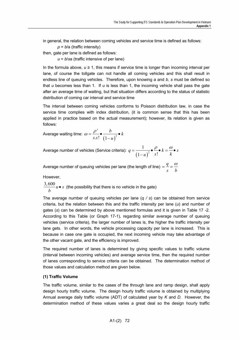
The Study for Supporting ITS Standards & Operation Plan Development in Vietnam Appendix 1
A1-(2) 72
in general, the relation between coming vehicles and service time is defined as follows: ρ = b/a (traffic intensity) then, gate per lane is defined as follows: u = b/sa (traffic intensive of per lane)
In the formula above, u ≥ 1, this means if service time is longer than incoming interval per lane, of course the tollgate can not handle all coming vehicles and this shall result in endless line of queuing vehicles. Therefore, upon knowing a and b, s must be defined so that u becomes less than 1. If u is less than 1, the incoming vehicle shall pass the gate after an average time of waiting, but that situation differs according to the status of statistic distribution of coming car interval and service time
The interval between coming vehicles conforms to Poisson distribution law, in case the service time complies with index distribution, (it is common sense that this has been applied in practice based on the actual measurement); however, its relation is given as follows:
Average waiting time: ( )2. ! 1
s b ks s uρω = • •
−
Average number of vehicles (Service criteria): ( )2
1!1
q k ss kuρ ω
= • • = •−
Average number of queuing vehicles per lane (the length of line) qs b
ω= =
However, 3,600 u sb
• (the possibility that there is no vehicle in the gate)
The average number of queuing vehicles per lane (q / s) can be obtained from service criteria, but the relation between this and the traffic intensity per lane (u) and number of gates (s) can be determined by above mentioned formulas and it is given in Table 17 -2. According to this Table (or Graph 17-1), regarding similar average number of queuing vehicles (service criteria), the larger number of lanes is, the higher the traffic intensity per lane gets. In other words, the vehicle processing capacity per lane is increased. This is because in case one gate is occupied, the next incoming vehicle may take advantage of the other vacant gate, and the efficiency is improved.
The required number of lanes is determined by giving specific values to traffic volume (interval between incoming vehicles) and average service time, then the required number of lanes corresponding to service criteria can be obtained. The determination method of those values and calculation method are given below.
(1) Traffic Volume
The traffic volume, similar to the cases of the through lane and ramp design, shall apply design hourly traffic volume. The design hourly traffic volume is obtained by multiplying Annual average daily traffic volume (ADT) of calculated year by K and D. However, the determination method of these values varies a great deal so the design hourly traffic
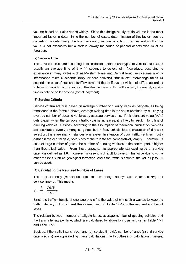
The Study for Supporting ITS Standards & Operation Plan Development in Vietnam Appendix 1
A1-(2) 73
volume based on it also varies widely. Since this design hourly traffic volume is the most important factor in determining the number of gates, determination of this factor requires discretion. In determining the final necessary volume, attention must be paid so that the value is not excessive but a certain leeway for period of phased construction must be foreseen.
(2) Service Time The service time differs according to toll collection method and types of vehicle, but it takes usually an average time of 8 ~ 14 seconds to collect toll. Nowadays, according to experience in many routes such as Meishin, Tomei and Central Road, service time in entry interchange takes 6 seconds (only for card delivery), that in exit interchange takes 14 seconds (in case of sectional tariff system and the tariff system which toll differs according to types of vehicle) as a standard. Besides, in case of flat tariff system, in general, service time is defined as 8 seconds (for toll payment).
(3) Service Criteria
Service criteria are built based on average number of queuing vehicles per gate, as being mentioned in the formula above, average waiting time is the value obtained by multiplying average number of queuing vehicles by average service time. If this standard value (q / s) gets bigger, when the temporary traffic volume increases, it is likely to result in long line of queuing vehicles. Besides, according to the assumption of theoretical calculation, vehicles are distributed evenly among all gates, but in fact, vehicle has a character of direction selection, there are many instances where even in situation of busy traffic, vehicles mostly gather in the central gate, both sides of the tollgate are comparatively empty. Therefore, in case of large number of gates, the number of queuing vehicles in the central part is higher than theoretical value. From those aspects, the appropriate standard value of service criteria is defined as 1.0. However, in case it is difficult to base on this value due to some other reasons such as geological formation, and if the traffic is smooth, the value up to 3.0 can be used.
(4) Calculating the Required Number of Lanes
The traffic intensity (ρ) can be obtained from design hourly traffic volume (DHV) and service time (b). This means
3,600b DHV ba
ρ = =
Since the traffic intensity of one lane u is ρ / s, the value of s in such a way as to keep the traffic intensity not to exceed the values given in Table 17-12 is the required number of lanes.
The relation between number of tollgate lanes, average number of queuing vehicles and the traffic intensity per lane, which are calculated by above formulas, is given in Table 17-1 and Table 17-2.
Besides, if the traffic intensity per lane (u), service time (b), number of lanes (s) and service criteria (q / s) are stipulated by these calculations, the hypothesis of calculation changes,

The Study for Supporting ITS Standards & Operation Plan Development in Vietnam Appendix 1
A1-(2) 74
but
3,600 u sb
•
is the number of process able vehicles per hour of that tollgate.
Table 2 Number of Tollgate Lanes (s), Average Number of Queuing Vehicles (q) and Traffic Intensity for a Tollgate Lane (u)
Average Number of Queuing Vehicles (q/s) Number of Tollgate Lanes 0.5 1.0 1.5 2.0 3.0 4.0 5.0 10.0
1 0.333 0.500 0.600 0.667 0.750 0.800 0.833 0.9092 0.577 0.706 0.775 0.817 0.863 0.895 0.913 0.9533 0.686 0.791 0.841 0.872 0.908 0.928 0.940 0.9694 0.748 0.835 0.876 0.902 0.929 0.945 0.955 0.9765 0.787 0.863 0.899 0.919 0.942 0.955 0.963 0.9816 0.817 0.883 0.914 0.932 0.952 0.962 0.969 0.9847 0.838 0.898 0.925 0.940 0.958 0.968 0.974 0.9868 0.854 0.909 0.933 0.948 0.964 0.972 0.977 0.9889 0.868 0.919 0.941 0.953 0.967 0.975 0.980 0.98910 0.878 0.926 0.946 0.957 0.970 0.977 0.982 0.99011 0.888 0.932 0.950 0.961 0.973 0.979 0.983 0.99112 0.896 0.936 0.954 0.964 0.975 0.981 0.984 0.99213 0.903 0.941 0.958 0.967 0.977 0.982 0.986 0.99214 0.908 0.945 0.961 0.969 0.979 0.983 0.987 0.99315 0.913 0.948 0.962 0.971 0.980 0.984 0.988 0.993
16. Preparation for Stepwise Implementation
The solutions for unification of system architecture, basic concept and actualization methods of automated toll collection are discussed in this volume of the Draft Design Standards. Further solutions are to be referred in other volumes as below.
(1) Establishment of connectability of communication network Draft Communication System Plan
(2) Establishment of inter-operability of message/data Draft Message/Data Standards (3) Establishment of compatibility of equipment components Draft General Specifications
Even in the ITS to be implemented in many different expressway sections, consistency among systems can be secured by premising the basic concept shown in the report and by complying with the provisions shown in the Draft ITS Standards. At the same time, the consistency among systems achieves stepwise ITS implementation keeping pace with the expressway construction by section.

DRAFT DESIGN STANDARDS (3)
Heavy Truck Control
(Ver.1.0: Final Version of the Study Results)

Documents and Volumes of Draft ITS Standards
The Draft ITS Standards consist of the following Documents:
• Draft Design Standards (volumes organized by the ITS user services) • Draft General Specifications (volumes organized by the functional packages) • Draft Message/Data Standards • Draft Communication System Plan
The Draft ITS Standards organized by 26 volumes shown below.
Draft Design Standards (3 Volumes)
(1) Traffic Information/Control (2) Automated Toll Collection
(3) Heavy Truck Control
Draft General Specifications (21 Volumes)
(1) Telephone Exchange (2) CCTV Monitoring (3) Event Detection (by Image) (4) Vehicle Detection (5) Traffic Analysis (6) Weather Monitoring (7) Traffic Event Data Management(8) Traffic Supervision (9) VMS Indication (10) Mobile Radio Communication(11) Traffic Information
(12) Lane Monitoring (13) Vehicle/Class Identification (14) Lane Control (15) Road-to-Vehicle Communication(16) IC-card Recording (17) Toll Management (18) OBU Management (19) Axle Load Measurement (20) Overloading Management (21) Center/Roadside Communication
(including Ducts) Draft Message/Data Standards (1 Volume)
Message List Data Dictionary
Draft Communication System Plan (1 Volume)
General Communication System Plan
Design Standards of CommunicationSystem
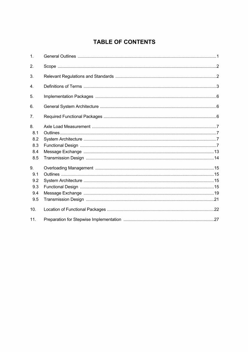
TABLE OF CONTENTS
1. General Outlines ......................................................................................................................1
2. Scope .......................................................................................................................................2
3. Relevant Regulations and Standards ......................................................................................2
4. Definitions of Terms .................................................................................................................3
5. Implementation Packages .......................................................................................................6
6. General System Architecture ...................................................................................................6
7. Required Functional Packages ................................................................................................6
8. Axle Load Measurement ..........................................................................................................7 8.1 Outlines.....................................................................................................................................7 8.2 System Architecture .................................................................................................................7 8.3 Functional Design ....................................................................................................................7 8.4 Message Exchange ...............................................................................................................13 8.5 Transmission Design .............................................................................................................14
9. Overloading Management .....................................................................................................15 9.1 Outlines ..................................................................................................................................15 9.2 System Architecture ...............................................................................................................15 9.3 Functional Design ..................................................................................................................15 9.4 Message Exchange ...............................................................................................................19 9.5 Transmission Design .............................................................................................................21
10. Location of Functional Packages ...........................................................................................22
11. Preparation for Stepwise Implementation .............................................................................27
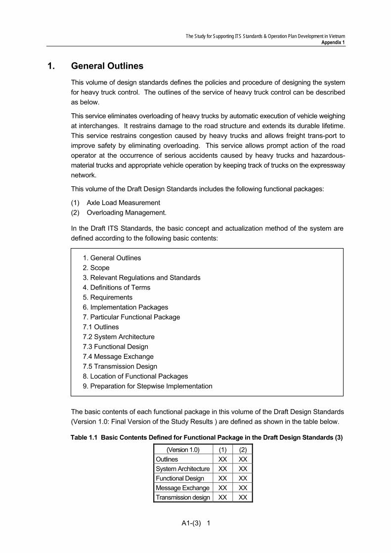
The Study for Supporting ITS Standards & Operation Plan Development in Vietnam Appendix 1
A1-(3) 1
1. General Outlines This volume of design standards defines the policies and procedure of designing the system for heavy truck control. The outlines of the service of heavy truck control can be described as below.
This service eliminates overloading of heavy trucks by automatic execution of vehicle weighing at interchanges. It restrains damage to the road structure and extends its durable lifetime. This service restrains congestion caused by heavy trucks and allows freight trans-port to improve safety by eliminating overloading. This service allows prompt action of the road operator at the occurrence of serious accidents caused by heavy trucks and hazardous-material trucks and appropriate vehicle operation by keeping track of trucks on the expressway network.
This volume of the Draft Design Standards includes the following functional packages: (1) Axle Load Measurement (2) Overloading Management.
In the Draft ITS Standards, the basic concept and actualization method of the system are defined according to the following basic contents:
1. General Outlines 2. Scope 3. Relevant Regulations and Standards 4. Definitions of Terms 5. Requirements 6. Implementation Packages 7. Particular Functional Package 7.1 Outlines 7.2 System Architecture 7.3 Functional Design 7.4 Message Exchange 7.5 Transmission Design 8. Location of Functional Packages 9. Preparation for Stepwise Implementation
The basic contents of each functional package in this volume of the Draft Design Standards (Version 1.0: Final Version of the Study Results ) are defined as shown in the table below.
Table 1.1 Basic Contents Defined for Functional Package in the Draft Design Standards (3)
(Version 1.0) (1) (2)Outlines XX XXSystem Architecture XX XXFunctional Design XX XXMessage Exchange XX XXTransmission design XX XX
The Study for Supporting ITS Standards & Operation Plan Development in Vietnam Appendix 1
A1-(3) 2
2. Scope This Draft Design Standards deal with the equipment components and software to be installed at roadside on the expressway network throughout Vietnam, including access sections of arterial roads, and in the Main Centers, road management offices and toll office of the expressway network for actualizing this functional package.
3. Relevant Regulations and Standards
The clauses in the Draft Standards of Heavy Truck Control are developed on the basis of or in reference to the following relevant regulations and standards. Some of the relevant regulations and standards need to be applied to specific ITS implementation projects in combination with the clauses in the Draft Standards of Heavy Truck Control.
(1) Circular 07/2010/TT-BGTVT: Legal regulation for measurement of overloaded heavy truck
(2) Decree No. 34/2010/ND-CP: stipulating on penalization due to administrative violations on the field of road traffic
(3) ISO 14813-1:2007: Intelligent transport systems – Refernce model architecture(s) for the ITS sentor – Part 1: ITS service domains, service groups and services
(4) ISO/IEC 11179: Information technology – specification and standardization of data elements
(5) ISO/DIS 14817: Transport information and control systems – requirements for an ITS/TICS central data registry and ITS/TICS data dictionaries
(6) ISO/CD 24533: Data directory and Message set for tracking of freight and It’s intermodal transfer
(7) Design manual of automatic weight measurement equipment for special vehicles by Kinki Management Office in Japan
The requirement standardization criteria in Viet Nam and the referential relation with the relevant regulations/standards are summarized in the following table.
<Standardization Criteria> • National: To be standardized by the Government • Local: to be standardized by MOT
<Referential relation with the Relevant Regulations/Standards> • The clause is developed on the basic of ##: the relevant regulations/standards • The clause is developed originally in reference to ##: the relevant regulations/standards • The clause is to be applied specific ITS implementation project in combination/reference
with ##: the relevant regulations/standards.
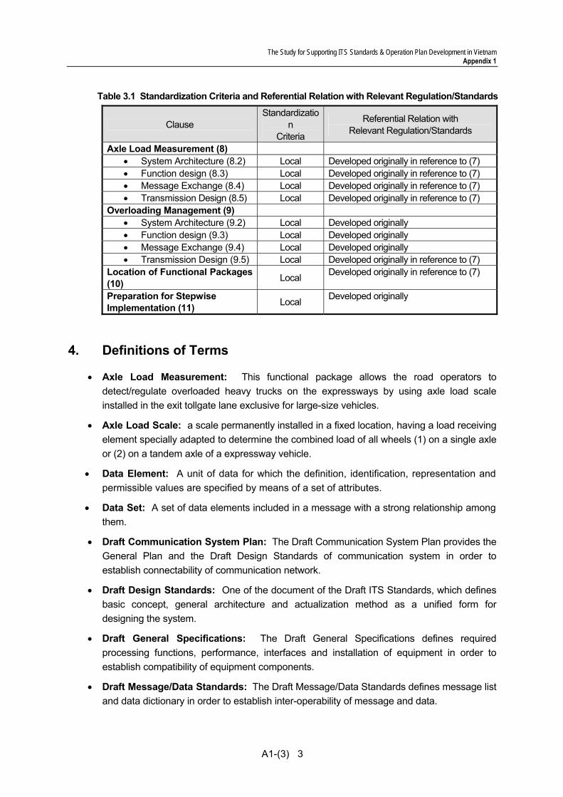
The Study for Supporting ITS Standards & Operation Plan Development in Vietnam Appendix 1
A1-(3) 3
Table 3.1 Standardization Criteria and Referential Relation with Relevant Regulation/Standards
Clause Standardizatio
n Criteria
Referential Relation with Relevant Regulation/Standards
Axle Load Measurement (8) • System Architecture (8.2) Local Developed originally in reference to (7) • Function design (8.3) Local Developed originally in reference to (7) • Message Exchange (8.4) Local Developed originally in reference to (7) • Transmission Design (8.5) Local Developed originally in reference to (7)
Overloading Management (9) • System Architecture (9.2) Local Developed originally • Function design (9.3) Local Developed originally • Message Exchange (9.4) Local Developed originally • Transmission Design (9.5) Local Developed originally in reference to (7)
Location of Functional Packages (10) Local Developed originally in reference to (7)
Preparation for Stepwise Implementation (11) Local Developed originally
4. Definitions of Terms
• Axle Load Measurement: This functional package allows the road operators to detect/regulate overloaded heavy trucks on the expressways by using axle load scale installed in the exit tollgate lane exclusive for large-size vehicles.
• Axle Load Scale: a scale permanently installed in a fixed location, having a load receiving element specially adapted to determine the combined load of all wheels (1) on a single axle or (2) on a tandem axle of a expressway vehicle.
• Data Element: A unit of data for which the definition, identification, representation and permissible values are specified by means of a set of attributes.
• Data Set: A set of data elements included in a message with a strong relationship among them.
• Draft Communication System Plan: The Draft Communication System Plan provides the General Plan and the Draft Design Standards of communication system in order to establish connectability of communication network.
• Draft Design Standards: One of the document of the Draft ITS Standards, which defines basic concept, general architecture and actualization method as a unified form for designing the system.
• Draft General Specifications: The Draft General Specifications defines required processing functions, performance, interfaces and installation of equipment in order to establish compatibility of equipment components.
• Draft Message/Data Standards: The Draft Message/Data Standards defines message list and data dictionary in order to establish inter-operability of message and data.

The Study for Supporting ITS Standards & Operation Plan Development in Vietnam Appendix 1
A1-(3) 4
• Equipment Component: The lowest subsystem of the system architecture, which is defined as the ordering unit for suppliers. Particulars of the Draft General Specifications are to be set up corresponding to the equipment components.
• ETC: Electronic Toll Collection (ETC), which is a toll collection method that eliminates the need for cash, tokens or credit cards to be used at tollbooths. Vehicles are equipped with small electronic devices that transmit both vehicle and account details through a reader located in the toll lane. The appropriate toll is then debited from the driver's prepaid account.
• Functional Package: A group of subsystems that have strong relationship to realize a certain function. Particulars of the Draft Design Standards and volumes of the Draft General Specifications are to be set up corresponding to the functional packages.
• Heavy Truck Control: An ITS user service for eliminating overloading of heavy trucks by automatic weighing at interchanges, restraining damage to the road structure, improving safety of the freight trans-port and restraining congestion caused by heavy trucks.
• Interchange: A junction connecting an expressway network and an arterial road network. That comprises grade separation and ramps to permit traffic on the expressway to pass through the junction without directly crossing other traffic on the arterial road.
• ISO: The International Organization for Standardization is an international-standard-setting body composed of representatives from various national standards organizations. Founded on February 23, 1947, the organization promulgates worldwide proprietary industrial and commercial standards.
• ITS User Service: A service to be provided by an ITS application to the users directly or indirectly.
• ITS: Intelligent Transport Systems (ITS) are systems to support transportation of goods and humans with information and communication technologies in order to efficiently and safely use the transport infrastructure and transport means (cars, trains, planes, ships...)
• Main Center: The Center in charge of traffic monitoring, traffic control and traffic information dissemination, and is to be cooperated with road management offices.
• Message: A set of data to be exchanged between subsystems for transferring information.
• Node: A node is a connection point is a connection point, either a redistribution point or a communication endpoint (some terminal equipment). The definition of a node depends on the network and protocol layer referred to. A physical network node is an active electronic device that is attached to a network, and is capable of sending, receiving, or forwarding information over a communications channel
• Overloading Management: This functional package allows the road operators to store/retrieve data of the heavy trucks overloaded on the expressways by using computers and software installed in the road management office.
• Road Management Office: An office in charge of patrol for surveying current traffic conditions on the expressway, and is to be equipped with the operation vehicles and the monitoring equipment for surveillance.
The Study for Supporting ITS Standards & Operation Plan Development in Vietnam Appendix 1
A1-(3) 5
• SDH: Synchronous Digital Hierarchy are standardized multiplexing protocols that transfer multiple digital bit streams over optical fiber using lasers or light-emitting diodes (LEDs). Lower data rates can also be transferred via an electrical interface.
• System Architecture: Diagrams indicated by the combination of subsystems and interfaces necessary for realizing a large system such as ITS. That should consist of several different kinds of diagrams, such as collaboration diagrams and message sequence diagrams in the notation of UML (Unified Modelling Language).
• Toll Office: A toll office is located at a tollgate, which includes two or more tollbooths, and is in charge of toll collection.
• Touch&Go: A toll payment method using a prepaid balance in IC-Card. Information contain in this card can be read and written via magnetic induction using specified radio frequency and IC-Card software. Each time passing through a tollgate, road user uses the IC-Card, the electronic card reader will deduct the exact fare from the value stored inside the card. User can top-up or reload the card with a pre-defined amount to continue using it.
• Vehicle Detection: This functional package allows the road operators to measure actual traffic volume, heavy vehicle ratio and vehicle velocity on the expressways for developing road operation/ improvement plans by using vehicle detectors installed at important points on the throughway and the tollgates.
• Vehicle Detector: A sensor either embedded in the pavement or mounted above the expressway to provide vehicle volume, speed, counts, headway, queue lengths, and vehicle classifications.

The Study for Supporting ITS Standards & Operation Plan Development in Vietnam Appendix 1
A1-(3) 6
5. Implementation Packages
The system for heavy truck control comprises the following implementation packages:
• Overloading Regulation • Center-to-center data exchange
Figure 5.1 Implementation Packages and Alternatives of Heavy Truck Control
6. General System Architecture
Diagrams of general system architecture of the implementation packages of heavy truck control are shown in the following pages.
Figure 6.1 Overloading Regulation by Weighing in Motion (G.S.A.)
7. Required Functional Packages
The following functional packages are required for structuring the system for heavy truck control system: • Axle Load Measurement • Overloading Management
Overloading RegulationHeavy Truck Control
(ITS User Service) (Implementation Package) (Alternatives)
(a) by Weighing in Motion
Center-to-Center Data Exchange
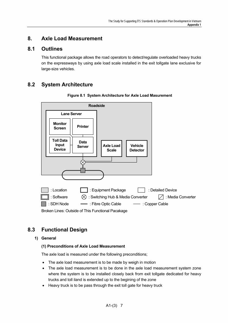
The Study for Supporting ITS Standards & Operation Plan Development in Vietnam Appendix 1
A1-(3) 7
8. Axle Load Measurement
8.1 Outlines This functional package allows the road operators to detect/regulate overloaded heavy trucks on the expressways by using axle load scale installed in the exit tollgate lane exclusive for large-size vehicles.
8.2 System Architecture
Figure 8.1 System Architecture for Axle Load Masurement
8.3 Functional Design 1) General
(1) Preconditions of Axle Load Measurement
The axle load is measured under the following preconditions;
• The axle load measurement is to be made by weigh in motion • The axle load measurement is to be done in the axle load measurement system zone
where the system is to be installed closely back from exit tollgate dedicated for heavy trucks and toll iland is extended up to the begining of the zone
• Heavy truck is to be pass through the exit toll gate for heavy truck
Roadside
Lane Server
Monitor Screen
: Switching Hub & Media Converter : Media Converter
: SDH Node
: Equipment Package : Location : Detailed Device
: Fibre Optic Cable : Copper Cable
Broken Lines: Outside of This Functional Pacakage
: Software
Data Server Vehicle
Detector
Printer
Axle LoadScale
Toll DataInput
Device
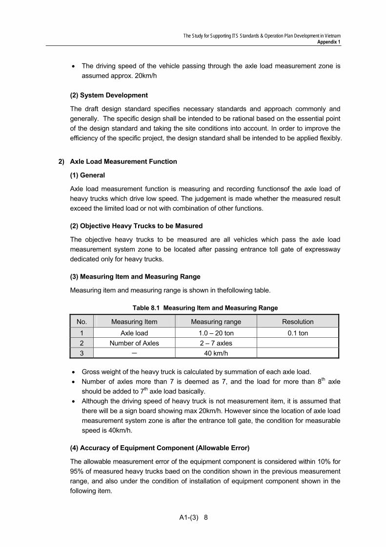
The Study for Supporting ITS Standards & Operation Plan Development in Vietnam Appendix 1
A1-(3) 8
• The driving speed of the vehicle passing through the axle load measurement zone is assumed approx. 20km/h
(2) System Development
The draft design standard specifies necessary standards and approach commonly and generally. The specific design shall be intended to be rational based on the essential point of the design standard and taking the site conditions into account. In order to improve the efficiency of the specific project, the design standard shall be intended to be applied flexibly.
2) Axle Load Measurement Function
(1) General
Axle load measurement function is measuring and recording functionsof the axle load of heavy trucks which drive low speed. The judgement is made whether the measured result exceed the limited load or not with combination of other functions.
(2) Objective Heavy Trucks to be Masured
The objective heavy trucks to be measured are all vehicles which pass the axle load measurement system zone to be located after passing entrance toll gate of expressway dedicated only for heavy trucks.
(3) Measuring Item and Measuring Range
Measuring item and measuring range is shown in thefollowing table.
Table 8.1 Measuring Item and Measuring Range
No. Measuring Item Measuring range Resolution
1 Axle load 1.0 – 20 ton 0.1 ton 2 Number of Axles 2 – 7 axles 3 - 40 km/h
• Gross weight of the heavy truck is calculated by summation of each axle load. • Number of axles more than 7 is deemed as 7, and the load for more than 8th axle
should be added to 7th axle load basically. • Although the driving speed of heavy truck is not measurement item, it is assumed that
there will be a sign board showing max 20km/h. However since the location of axle load measurement system zone is after the entrance toll gate, the condition for measurable speed is 40km/h.
(4) Accuracy of Equipment Component (Allowable Error)
The allowable measurement error of the equipment component is considered within 10% for 95% of measured heavy trucks baed on the condition shown in the previous measurement range, and also under the condition of installation of equipment component shown in the following item.

The Study for Supporting ITS Standards & Operation Plan Development in Vietnam Appendix 1
A1-(3) 9
(5) Installation Condition of Equipment Component
The equipment installation condition to be guaranteed for the previous error rate is shown below;
• Gradient Ratio: Cross and longitudinal slope ratio should be within 2%. • Roadsurface dent due to track: The roadsurface should be well maintained that there
should not be observerved apparent rolling or pitching of the heavy truck visually.
(6) Self-diagnostic Function
The operation conditions of the equipment components are monitored by this self-diagnostic function, and in-case some failure is detected, measurement and further process is halted. The self-diagnostic information is to be transmitted always to the roadside equipment component automatically regardless the diagnostic result (normal or failure).
(6-1) Self-diagnostic result
The following self-diagnostic result is required to monitor:
• Normal: the status of “Normal” is defined that there is no fault, failure or defect found by the self-diagnostic and the measurement result is reliable.
• Failure: the status of “Failure” is defined that some failure is detected and measurement result is not able to reliable. This status is automatically set once some failure of the equipment component is detected by the self-diagnostic function.
(6-2)Notification function of self-diagnosic result
Self-diagnostic result is transmitted to the roadside equipment component at all time. In case status of “failure” is detected, the self-diagnostic result is required to identify what kind of failure it is, and that status is required to transmit to the roadside equipment component.
3) Heavy Truck Information Collection Function
(1) General
The objective of this function is to obtain the heavy truck identifying information for the heavy trucks passing through the axle load measurement system zone. The information to be obtained is photo of heavy truck front part and photos to be utilized for identifying licence number which is to be stated in the Overloading Management.
(2) Photographic Subject
All vehicles passing thourh the axle load measurement system zone which is to be installed after passing through entrance toll gate of expressway for heavy trucks are the photographic subject. The shooting is required for front part of vehicle.
(3) Conditions of Photography
• The driving vehicle is taken for one front part. • Image extraction is required for licence plate number part of the photo and the capacity
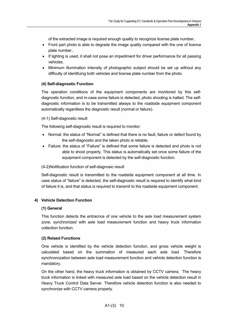
The Study for Supporting ITS Standards & Operation Plan Development in Vietnam Appendix 1
A1-(3) 10
of the extracted image is required enough quality to recognize license plate number.. • Front part photo is able to degrade the image quality compared with the one of licence
plate number.. • If lighting is used, it shall not pose an impediment for driver performance for all passing
vehicles. • Minimum illumination intensity of photographic subject should be set up without any
difficulty of identifuing both vehicles and license plate number from the photo.
(4) Self-diagnostic Function
The operation conditions of the equipment components are monitored by this self-diagnostic function, and in-case some failure is detected, photo shooting is halted. The self-diagnostic information is to be transmitted always to the roadside equipment component automatically regardless the diagnostic result (normal or failure).
(4-1) Self-diagnostic result
The following self-diagnostic result is required to monitor:
• Normal: the status of “Normal” is defined that there is no fault, failure or defect found by the self-diagnostic and the taken photo is reliable.
• Failure: the status of “Failure” is defined that some failure is detected and photo is not able to shoot properly. This status is automatically set once some failure of the equipment component is detected by the self-diagnostic function.
(4-2)Notification function of self-diagnosic result
Self-diagnostic result is transmitted to the roadside equipment component at all time. In case status of “failure” is detected, the self-diagnostic result is required to identify what kind of failure it is, and that status is required to transmit to the roadside equipment component.
4) Vehicle Detection Function
(1) General
This function detects the entracnce of one vehicle to the axle load measurement system zone, synchronized with axle load measurement function and heavy truck information collection function.
(2) Relaed Functions
One vehicle is identified by the vehicle detection function, and gross vehicle weight is calculated based on the summation of measured each axle load. Therefore synchronozation between axle load measurement function and vehicle detection function is mandatory.
On the other hand, the heavy truck information is obtained by CCTV camera. The heavy truck information is linked with measured axle load based on the vehicle detection result in Heavy Truck Control Data Server. Therefore vehicle detection function is also needed to synchronize with CCTV camera properly.
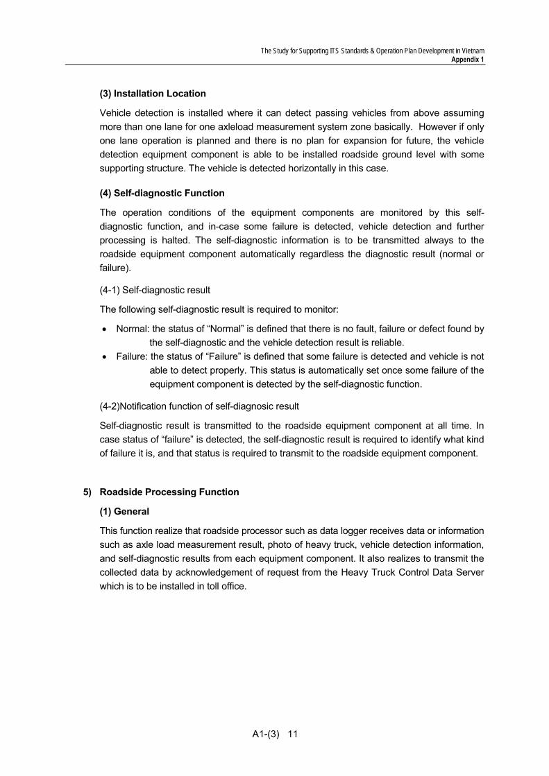
The Study for Supporting ITS Standards & Operation Plan Development in Vietnam Appendix 1
A1-(3) 11
(3) Installation Location
Vehicle detection is installed where it can detect passing vehicles from above assuming more than one lane for one axleload measurement system zone basically. However if only one lane operation is planned and there is no plan for expansion for future, the vehicle detection equipment component is able to be installed roadside ground level with some supporting structure. The vehicle is detected horizontally in this case.
(4) Self-diagnostic Function
The operation conditions of the equipment components are monitored by this self-diagnostic function, and in-case some failure is detected, vehicle detection and further processing is halted. The self-diagnostic information is to be transmitted always to the roadside equipment component automatically regardless the diagnostic result (normal or failure).
(4-1) Self-diagnostic result
The following self-diagnostic result is required to monitor:
• Normal: the status of “Normal” is defined that there is no fault, failure or defect found by the self-diagnostic and the vehicle detection result is reliable.
• Failure: the status of “Failure” is defined that some failure is detected and vehicle is not able to detect properly. This status is automatically set once some failure of the equipment component is detected by the self-diagnostic function.
(4-2)Notification function of self-diagnosic result
Self-diagnostic result is transmitted to the roadside equipment component at all time. In case status of “failure” is detected, the self-diagnostic result is required to identify what kind of failure it is, and that status is required to transmit to the roadside equipment component.
5) Roadside Processing Function
(1) General
This function realize that roadside processor such as data logger receives data or information such as axle load measurement result, photo of heavy truck, vehicle detection information, and self-diagnostic results from each equipment component. It also realizes to transmit the collected data by acknowledgement of request from the Heavy Truck Control Data Server which is to be installed in toll office.
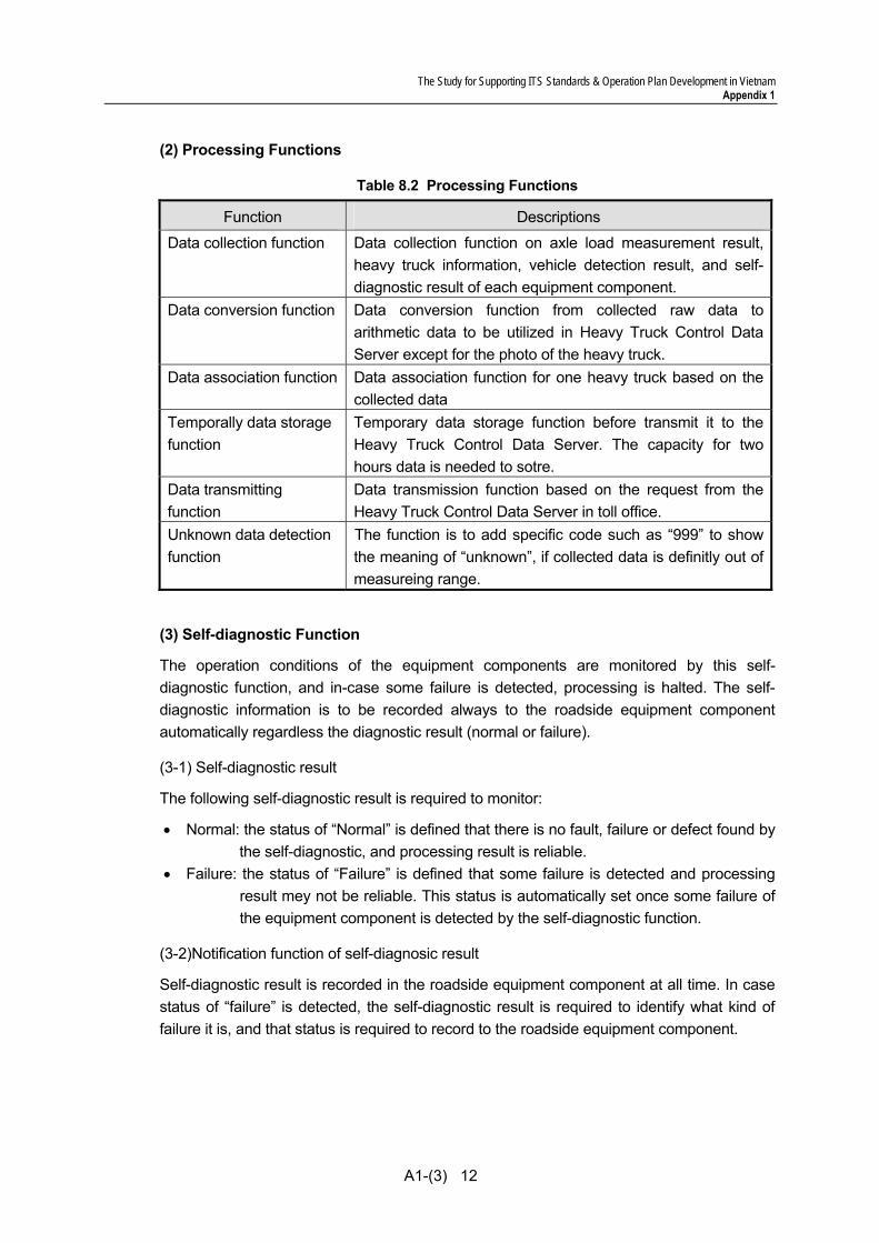
The Study for Supporting ITS Standards & Operation Plan Development in Vietnam Appendix 1
A1-(3) 12
(2) Processing Functions
Table 8.2 Processing Functions
Function Descriptions
Data collection function Data collection function on axle load measurement result, heavy truck information, vehicle detection result, and self-diagnostic result of each equipment component.
Data conversion function Data conversion function from collected raw data to arithmetic data to be utilized in Heavy Truck Control Data Server except for the photo of the heavy truck.
Data association function Data association function for one heavy truck based on the collected data
Temporally data storage function
Temporary data storage function before transmit it to the Heavy Truck Control Data Server. The capacity for two hours data is needed to sotre.
Data transmitting function
Data transmission function based on the request from the Heavy Truck Control Data Server in toll office.
Unknown data detection function
The function is to add specific code such as “999” to show the meaning of “unknown”, if collected data is definitly out of measureing range.
(3) Self-diagnostic Function
The operation conditions of the equipment components are monitored by this self-diagnostic function, and in-case some failure is detected, processing is halted. The self-diagnostic information is to be recorded always to the roadside equipment component automatically regardless the diagnostic result (normal or failure).
(3-1) Self-diagnostic result
The following self-diagnostic result is required to monitor:
• Normal: the status of “Normal” is defined that there is no fault, failure or defect found by the self-diagnostic, and processing result is reliable.
• Failure: the status of “Failure” is defined that some failure is detected and processing result mey not be reliable. This status is automatically set once some failure of the equipment component is detected by the self-diagnostic function.
(3-2)Notification function of self-diagnosic result
Self-diagnostic result is recorded in the roadside equipment component at all time. In case status of “failure” is detected, the self-diagnostic result is required to identify what kind of failure it is, and that status is required to record to the roadside equipment component.
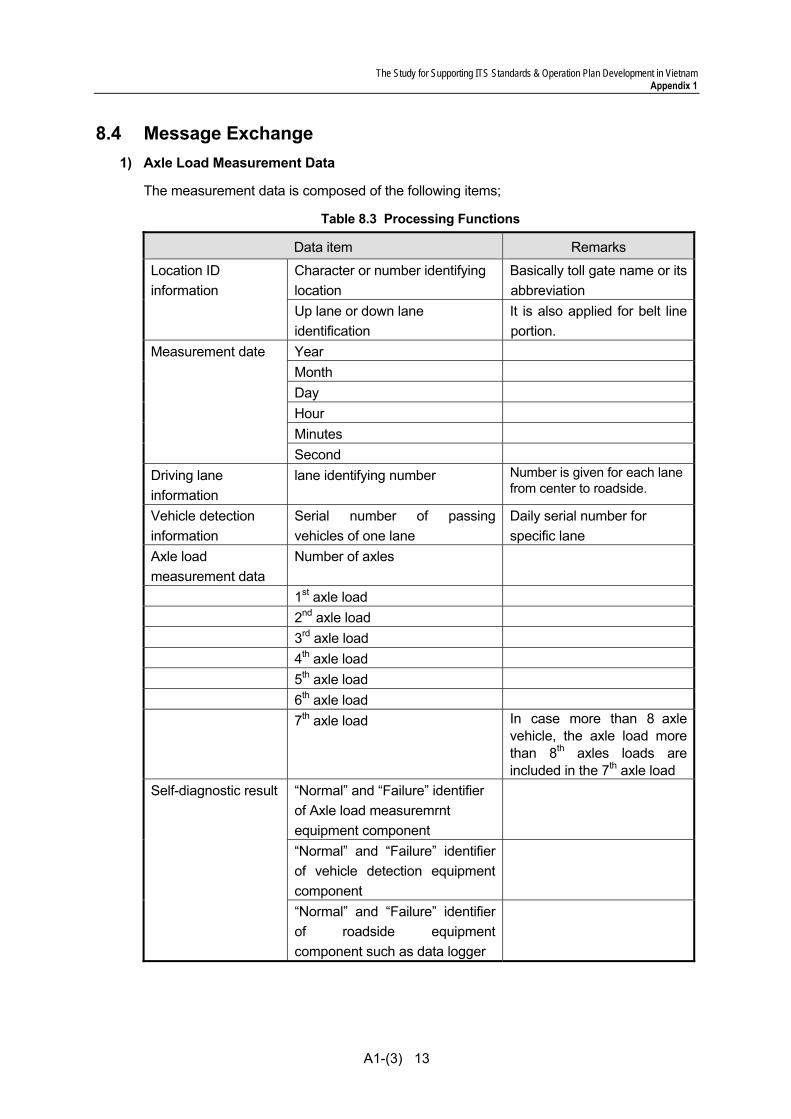
The Study for Supporting ITS Standards & Operation Plan Development in Vietnam Appendix 1
A1-(3) 13
8.4 Message Exchange 1) Axle Load Measurement Data
The measurement data is composed of the following items;
Table 8.3 Processing Functions
Data item Remarks
Character or number identifying location
Basically toll gate name or its abbreviation
Location ID information
Up lane or down lane identification
It is also applied for belt line portion.
Year Month Day Hour Minutes
Measurement date
Second Driving lane information
lane identifying number Number is given for each lane from center to roadside.
Vehicle detection information
Serial number of passing vehicles of one lane
Daily serial number for specific lane
Axle load measurement data
Number of axles
1st axle load 2nd axle load 3rd axle load 4th axle load 5th axle load 6th axle load 7th axle load In case more than 8 axle
vehicle, the axle load more than 8th axles loads are included in the 7th axle load
“Normal” and “Failure” identifier of Axle load measuremrnt equipment component
“Normal” and “Failure” identifier of vehicle detection equipment component
Self-diagnostic result
“Normal” and “Failure” identifier of roadside equipment component such as data logger
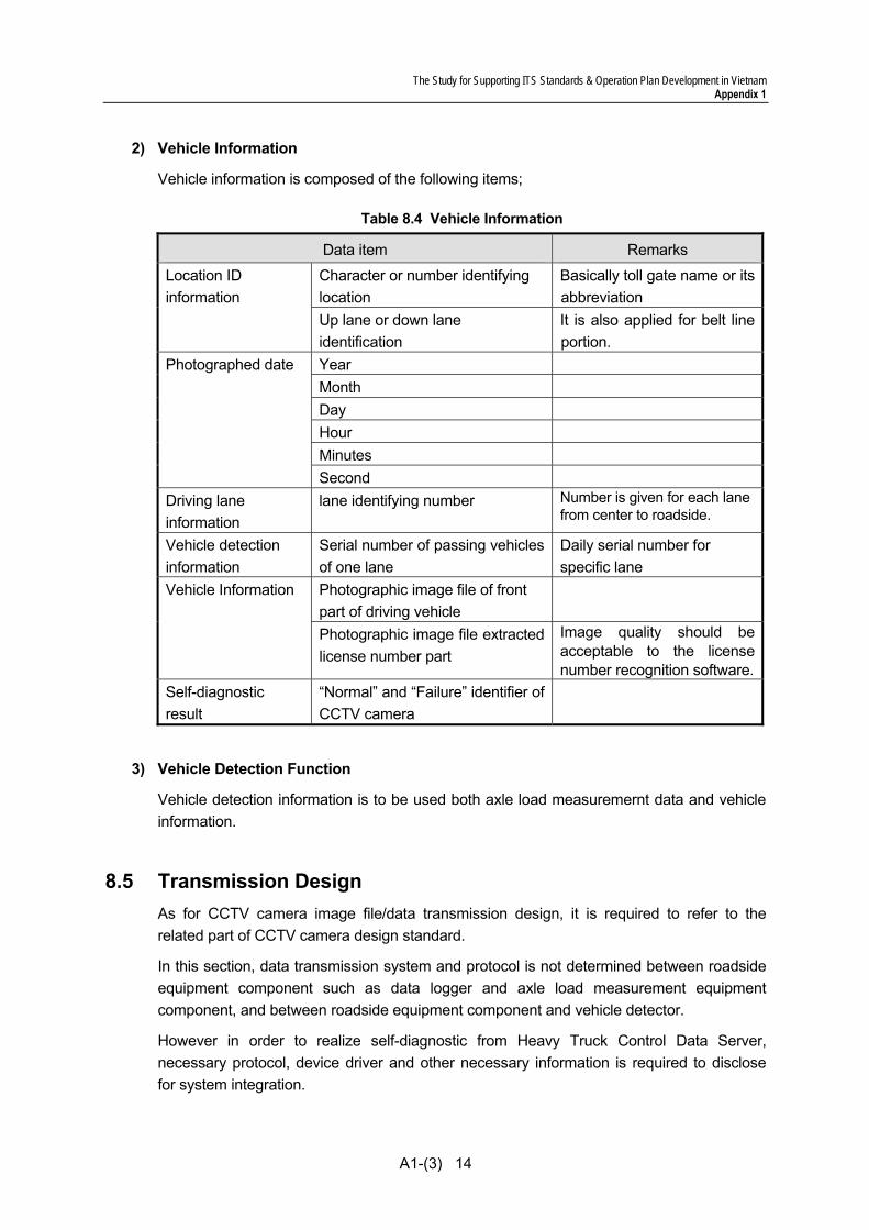
The Study for Supporting ITS Standards & Operation Plan Development in Vietnam Appendix 1
A1-(3) 14
2) Vehicle Information
Vehicle information is composed of the following items;
Table 8.4 Vehicle Information
Data item Remarks
Character or number identifying location
Basically toll gate name or its abbreviation
Location ID information
Up lane or down lane identification
It is also applied for belt line portion.
Year Month Day Hour Minutes
Photographed date
Second Driving lane information
lane identifying number Number is given for each lane from center to roadside.
Vehicle detection information
Serial number of passing vehicles of one lane
Daily serial number for specific lane
Photographic image file of front part of driving vehicle
Vehicle Information
Photographic image file extracted license number part
Image quality should be acceptable to the license number recognition software.
Self-diagnostic result
“Normal” and “Failure” identifier of CCTV camera
3) Vehicle Detection Function
Vehicle detection information is to be used both axle load measuremernt data and vehicle information.
8.5 Transmission Design As for CCTV camera image file/data transmission design, it is required to refer to the related part of CCTV camera design standard.
In this section, data transmission system and protocol is not determined between roadside equipment component such as data logger and axle load measurement equipment component, and between roadside equipment component and vehicle detector.
However in order to realize self-diagnostic from Heavy Truck Control Data Server, necessary protocol, device driver and other necessary information is required to disclose for system integration.
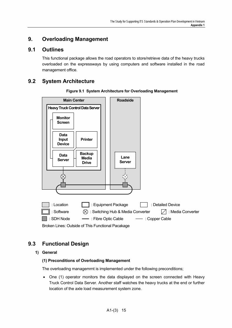
The Study for Supporting ITS Standards & Operation Plan Development in Vietnam Appendix 1
A1-(3) 15
9. Overloading Management
9.1 Outlines This functional package allows the road operators to store/retrieve data of the heavy trucks overloaded on the expressways by using computers and software installed in the road management office.
9.2 System Architecture Figure 9.1 System Architecture for Overloading Management
9.3 Functional Design 1) General
(1) Preconditions of Overloading Management
The overloading managemrnt is implemented under the following preconditions;
• One (1) operator monitors the data displayed on the screen connected with Heavy Truck Control Data Server. Another staff watches the heavy trucks at the end or further location of the axle load measurement system zone.
Roadside Main Center
Heavy Truck Control Data Server
Monitor Screen
Printer
Backup Media Drive
Data Server
: Switching Hub & Media Converter : Media Converter
: SDH Node
: Equipment Package : Location : Detailed Device
: Fibre Optic Cable : Copper Cable
Broken Lines: Outside of This Functional Pacakage
: Software
Data Input
Device
Lane Server

The Study for Supporting ITS Standards & Operation Plan Development in Vietnam Appendix 1
A1-(3) 16
(2) System Development
The draft design standard specifies necessary standards and approach commonly and generally. The specific design shall be intended to be rational based on the essential point of the design standard and taking the site conditions into account. In order to improve the efficiency of the specific project, the design standard shall be intended to be applied flexibly.
2) Functions for Collected Data
(1) Recording Function of Axle Load Measurement and Heavy Truck Information
The collected data from roadside equipment components is required to associate axle load measurement result with heavy truck information properly and needed to be recorded as one (1) vehicle data.
There are two (2) types of data for vehicle information. One is photographic image and the other is recognized licence plate number form photo image collected form the roadside. Since the original photographic image is taken by CCTV camera, operator or small animals crossing on the axle load measurement equipment component might be taken. Although such cases will be very few, the association between axle load measurement result and vehicle information is required to be properly processed without any contradiction in Heavy Truck Control Data Server.
The original photographic image is required to keep necessary quality up to completion of license plagte number recognition, however necessary image quality for recording to Heavy Truck Control Data Server is recommended to reduce. The file size of photo image for recording is needed around 100Kbyte. The file format is recommended widely diffused type such as JPEG.
(2) Handling Method of “Unknown” Data
If measurement results with out of measuring range are assumed to be detected, a code number showing “unknown” is to be added with the unknown data. However after completion of data association process and then one vehicle data set is compiled, operator is required to check its effectiveness. The automatic screening function for such data is required however it is not applied in the initial operation stage.
(3) Search Function for Compiled Data
Axle load measurement result is compiled in the Heavy Truck Control Data Server associated with corresponding heavy truck information. For such compiloed data, search function with parameters such as date, measured axle load, gross weight of heavy truck, license number, and others is necessary for check, review or comparison.
The search result is needed to be displayed on the screen with search parameters and other parameters such as heavy truck photo image with list format at least.
(4) Print OLut Function
The above search result is also required to be printed out. The priont out function for any

The Study for Supporting ITS Standards & Operation Plan Development in Vietnam Appendix 1
A1-(3) 17
one vehicle data set including measurement result and vehicle information is also required in normal operation.
(5) Backup of Compiled Data
In order to avoid data loss, the compiled data in Heavy Truck Control Data Serve is recommendedn to make a back up periodically. Although the capacity of the server is required two years data volume at least in general specifications, monthly backup in real operation is recommended to avoid the data loss.
3) Overloading Judgement Function
Overloading judgement is made in the following procedure;
• Grossweight of heavy truck is calculated baed on the measured result and the vehicle detection data
• Judgement is made wheter measured axle load and/or gross weight of heavy truck exceeds the threshold configured in advance.
According to the Circular 07/2010/TT-BGTVT, the vehicle is deemed as violation of overloading in case the measured axle load exceeds 1.1 times of the stipulated limit of the above Circular. On the other hand, there is 10% allowable measurement error of the measureing equipment components as explained in the item of Axle Load Measurement. Therefore 1.21 times of the stipulated limit load of the above Circular is able to be deemed as violation. For example, the axle load limit is stipulated as 10 ton in the Circular, and if measurement result of 12.2 ton is obtained for one axle load, it is able to be deemed as violation.
As for the gross weight of heavy truck, it is deemed as violation in case the measured result exceeds the limit stipulated in the above circular. In this case, the measurement error of 10 % is required to consider as well, therefore 1.1 times of the stipulated limit load of the above circular is able to be deemed as violation. For example, the gross weight limit of heavy truck stipulated as 30 ton in the Circular, and if measurement result obtained 33.1 ton, it is able to be deemed as violation.
As a whole, the threshold to judge overload is necessary to consider properly.
4) Alert Notification Function
In case overloading is detected, the alert of the fact is required to be notified to the operatoer and another staff immediately. Since the operator is monitoring in toll office, and the another staff waches heavy trucks outside, the alert is required for them respectively.
5) License Plate Number Recognition Function
(1) General
This function realizes recognition of license plate number based on the photograph of the license plate number of the heavy truck.

The Study for Supporting ITS Standards & Operation Plan Development in Vietnam Appendix 1
A1-(3) 18
(2) Objective Vehicles
The objective heavy trucks to be recognized are all vehicles which pass the axle load measurement system zone to be located after passing entrance toll gate of expressway dedicated only for heavy trucks.
(3) Recongnition Items
Recongnition items are all types of numbers specified in the document under Circular No 06/2009/TT-BCA(C11), Ministry of Public and Security
(4) Recognition Rate
Recognition rate is 95% or more under the driving condition to secure this rate shown in the next item.
(5) Driving Condition to Secure Specified Recognition Rate
Driving condition to secure specified recognition rate specified in item (4) above is shown below;
Table 9.1 Driving Condition to Secure Specified Recognition Rate
Item Condition
Tire passing track Within the lane (all tires are passing within the lane during vehicle photo taking time)
Driving speed of vehicle Maximum 40km/h Angle between lane direction and vehicle driving direction
Within 5 degree
Angles of licenseplate number fixing to the vehicle
Horizontal angle: within 5 degree Vertical angle: within 10 degree
Note) Vehicles with the following conditions are excluded from number recognition.
• Photo image is not clear due to sunlight, vehicle light or negative effect of road surface • Driving vehicles deviated from the above conditions • Vehicles with dirty, broken, or bent license number plate
6) Failure Detection Function
This function detects the failure of the roadside equipment components and notifys it to the operator by screen of Heavy Truck Control Data Server or other method. The roadside equipment components failure including axle load measurement equipment component, vehicle detector, CCTV camera, and data logger is detected based on the self-diagnostic results transmitted from the data logger.
Failure is required to be distinguished by some method such as code number. The precondition on this matter is proper handling method of each failure should be documented and delivered from the contractor or manufacturer to the expressway operator when those equipment components are handed over.
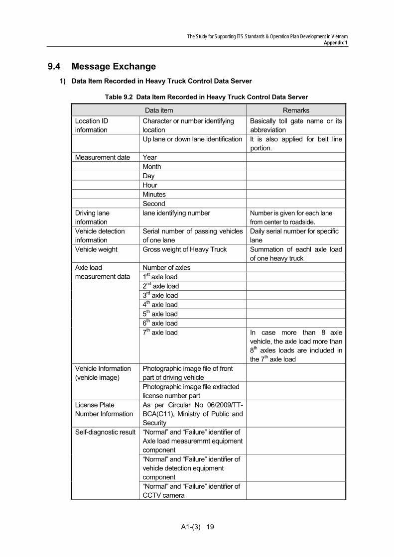
The Study for Supporting ITS Standards & Operation Plan Development in Vietnam Appendix 1
A1-(3) 19
9.4 Message Exchange 1) Data Item Recorded in Heavy Truck Control Data Server
Table 9.2 Data Item Recorded in Heavy Truck Control Data Server
Data item Remarks Location ID information
Character or number identifying location
Basically toll gate name or its abbreviation
Up lane or down lane identification It is also applied for belt line portion.
Measurement date Year Month Day Hour Minutes Second Driving lane information
lane identifying number Number is given for each lane from center to roadside.
Vehicle detection information
Serial number of passing vehicles of one lane
Daily serial number for specific lane
Vehicle weight Gross weight of Heavy Truck Summation of eachl axle load of one heavy truck
Number of axles 1st axle load 2nd axle load 3rd axle load 4th axle load 5th axle load 6th axle load
Axle load measurement data
7th axle load In case more than 8 axle vehicle, the axle load more than 8th axles loads are included in the 7th axle load
Photographic image file of front part of driving vehicle
Vehicle Information (vehicle image)
Photographic image file extracted license number part
License Plate Number Information
As per Circular No 06/2009/TT-BCA(C11), Ministry of Public and Security
“Normal” and “Failure” identifier of Axle load measuremrnt equipment component
“Normal” and “Failure” identifier of vehicle detection equipment component
Self-diagnostic result
“Normal” and “Failure” identifier of CCTV camera
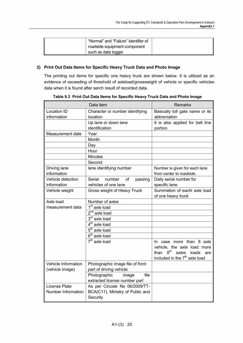
The Study for Supporting ITS Standards & Operation Plan Development in Vietnam Appendix 1
A1-(3) 20
“Normal” and “Failure” identifier of roadside equipment component such as data logger
2) Print Out Data Items for Specific Heavy Truck Data and Photo Image
The printing out items for specific one heavy truck are shown below. It is utilized as an evidence of exceeding of threshold of axleload/grossweight of vehicle or specific vehicles data when it is found after serch result of recorded data.
Table 9.3 Print Out Data Items for Specific Heavy Truck Data and Photo Image
Data item Remarks Location ID information
Character or number identifying location
Basically toll gate name or its abbreviation
Up lane or down lane identification
It is also applied for belt line portion.
Measurement date Year Month Day Hour Minutes Second Driving lane information
lane identifying number Number is given for each lane from center to roadside.
Vehicle detection information
Serial number of passing vehicles of one lane
Daily serial number for specific lane
Vehicle weight Gross weight of Heavy Truck Summation of eachl axle load of one heavy truck
Number of axles 1st axle load 2nd axle load 3rd axle load 4th axle load 5th axle load 6th axle load
Axle load measurement data
7th axle load In case more than 8 axle vehicle, the axle load more than 8th axles loads are included in the 7th axle load
Photographic image file of front part of driving vehicle
Vehicle Information (vehicle image)
Photographic image file extracted license number part
License Plate Number Information
As per Circular No 06/2009/TT-BCA(C11), Ministry of Public and Security

The Study for Supporting ITS Standards & Operation Plan Development in Vietnam Appendix 1
A1-(3) 21
9.5 Transmission Design Data Transmission between Heavy Truck Control Data Server and roadside equipment component such as data logger is considered to apply TCP/IP and Ethernet. The data transmitting procedure is originating and fetching from the Heavy Truck Control Data Server basically.
In order to realize self-diagnostic from Heavy Truck Control Data Server, protocol, device driver and other necessary information is required to disclose for system integration whenever necessary.
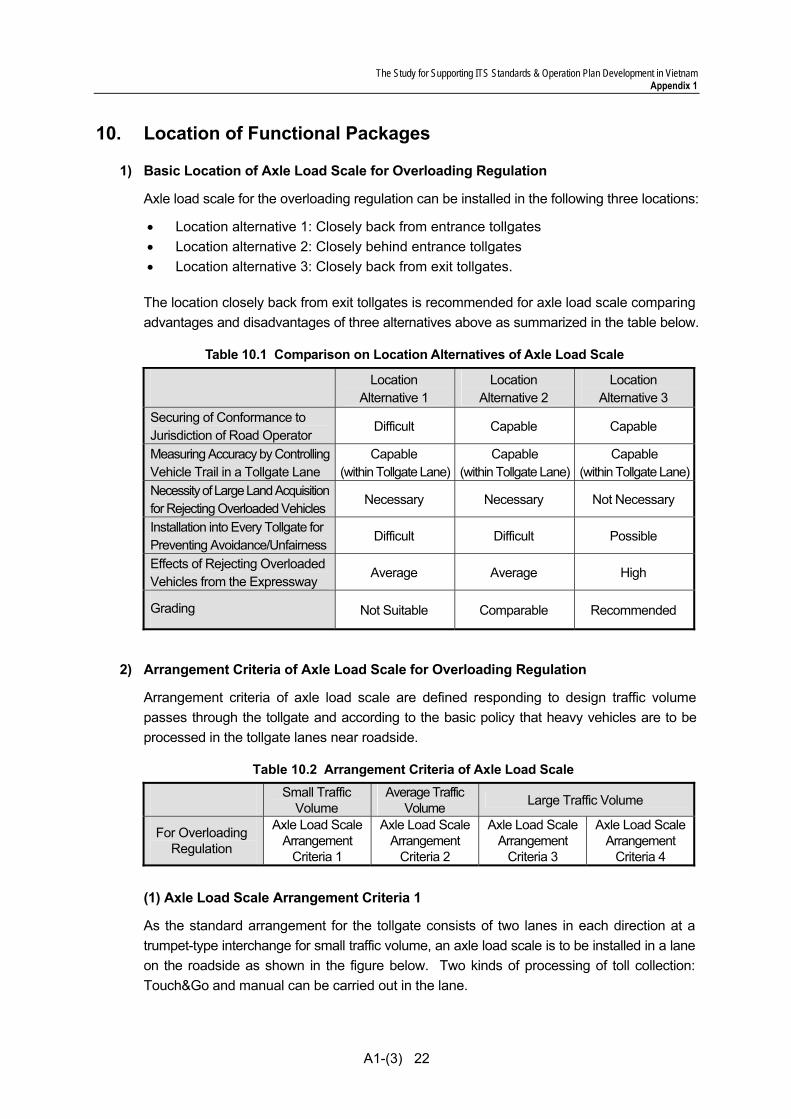
The Study for Supporting ITS Standards & Operation Plan Development in Vietnam Appendix 1
A1-(3) 22
10. Location of Functional Packages
1) Basic Location of Axle Load Scale for Overloading Regulation
Axle load scale for the overloading regulation can be installed in the following three locations:
• Location alternative 1: Closely back from entrance tollgates • Location alternative 2: Closely behind entrance tollgates • Location alternative 3: Closely back from exit tollgates.
The location closely back from exit tollgates is recommended for axle load scale comparing advantages and disadvantages of three alternatives above as summarized in the table below.
Table 10.1 Comparison on Location Alternatives of Axle Load Scale
Location Alternative 1
Location Alternative 2
Location Alternative 3
Securing of Conformance to Jurisdiction of Road Operator
Difficult Capable Capable
Measuring Accuracy by ControllingVehicle Trail in a Tollgate Lane
Capable (within Tollgate Lane)
Capable (within Tollgate Lane)
Capable (within Tollgate Lane)
Necessity of Large Land Acquisitionfor Rejecting Overloaded Vehicles
Necessary Necessary Not Necessary
Installation into Every Tollgate for Preventing Avoidance/Unfairness
Difficult Difficult Possible
Effects of Rejecting Overloaded Vehicles from the Expressway
Average Average High
Grading Not Suitable Comparable Recommended
2) Arrangement Criteria of Axle Load Scale for Overloading Regulation
Arrangement criteria of axle load scale are defined responding to design traffic volume passes through the tollgate and according to the basic policy that heavy vehicles are to be processed in the tollgate lanes near roadside.
Table 10.2 Arrangement Criteria of Axle Load Scale
Small Traffic Volume
Average Traffic Volume Large Traffic Volume
For Overloading Regulation
Axle Load Scale Arrangement
Criteria 1
Axle Load Scale Arrangement
Criteria 2
Axle Load Scale Arrangement
Criteria 3
Axle Load Scale Arrangement
Criteria 4 (1) Axle Load Scale Arrangement Criteria 1
As the standard arrangement for the tollgate consists of two lanes in each direction at a trumpet-type interchange for small traffic volume, an axle load scale is to be installed in a lane on the roadside as shown in the figure below. Two kinds of processing of toll collection: Touch&Go and manual can be carried out in the lane.

The Study for Supporting ITS Standards & Operation Plan Development in Vietnam Appendix 1
A1-(3) 23
Figure 10.1 Axle Load Scale Arrangement at Trumpet-Type Interchange for Small Traffic Volume
(2) Axle Load Scale Arrangement Criteria 2
As the standard arrangement for the tollgate consists of three lanes in each direction at a trumpet-type interchange for middle traffic volume, axle load scales are to be installed in two lanes near the roadside of the exit tollgate as shown in the figure below. Vehicles equipped for ETC can be processed at the center lane and other vehicles can be processed at the lane on the roadside.
Figure 10.2 Axle Load Scale Arrangement at Trumpet-Type Interchange for Small Traffic Volume
(3) Axle Load Scale Arrangement Criteria 3
As the standard arrangement for the tollgate consists of four lanes in each direction at a trumpet-type interchange for large traffic volume, axle load scales are to be installed in two lanes near the roadside of the exit tollgate as shown in the figure below. Vehicles equipped for ETC can be processed at the second lane from the roadside and the other vehicles can be processed at the lane on the roadside.
And in the case of the tollgate consists of five or six lanes in each direction at a trumpet-type interchange, axle load scales are to be installed three lanes near the roadside of the exit tollgate as shown in the figure below. Vehicles equipped for ETC can be processed at the second or third lane from the roadside and the other vehicles can be processed at the lane on the roadside.
Touch&Go/ManualManual Axle Load Scale
ETCManual Axle Load Scale
Exit
Entra
nce
Exit
Entra
nce
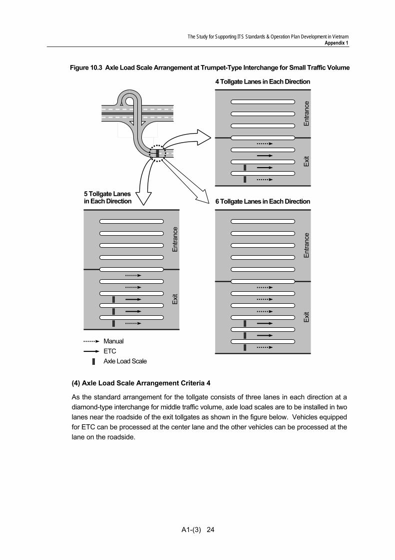
The Study for Supporting ITS Standards & Operation Plan Development in Vietnam Appendix 1
A1-(3) 24
Figure 10.3 Axle Load Scale Arrangement at Trumpet-Type Interchange for Small Traffic Volume
(4) Axle Load Scale Arrangement Criteria 4
As the standard arrangement for the tollgate consists of three lanes in each direction at a diamond-type interchange for middle traffic volume, axle load scales are to be installed in two lanes near the roadside of the exit tollgates as shown in the figure below. Vehicles equipped for ETC can be processed at the center lane and the other vehicles can be processed at the lane on the roadside.
5 Tollgate Lanes in Each Direction
4 Tollgate Lanes in Each Direction
6 Tollgate Lanes in Each Direction
ETC Manual
Axle Load Scale
Exit
En
tranc
e
Exit
En
tranc
e
Exit
En
tranc
e
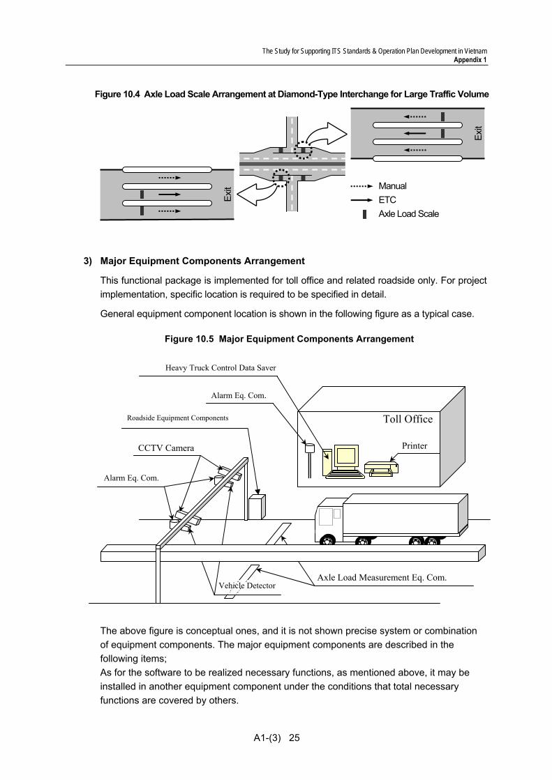
The Study for Supporting ITS Standards & Operation Plan Development in Vietnam Appendix 1
A1-(3) 25
Figure 10.4 Axle Load Scale Arrangement at Diamond-Type Interchange for Large Traffic Volume
3) Major Equipment Components Arrangement
This functional package is implemented for toll office and related roadside only. For project implementation, specific location is required to be specified in detail.
General equipment component location is shown in the following figure as a typical case.
Figure 10.5 Major Equipment Components Arrangement
The above figure is conceptual ones, and it is not shown precise system or combination of equipment components. The major equipment components are described in the following items; As for the software to be realized necessary functions, as mentioned above, it may be installed in another equipment component under the conditions that total necessary functions are covered by others.
ETC Manual
Axle Load Scale
Exit
Exit
Axle Load Measurement Eq. Com.
CCTV Camera
Toll Office
Heavy Truck Control Data Saver
Printer
Roadside Equipment Components
Vehicle Detector
Alarm Eq. Com.
Alarm Eq. Com.
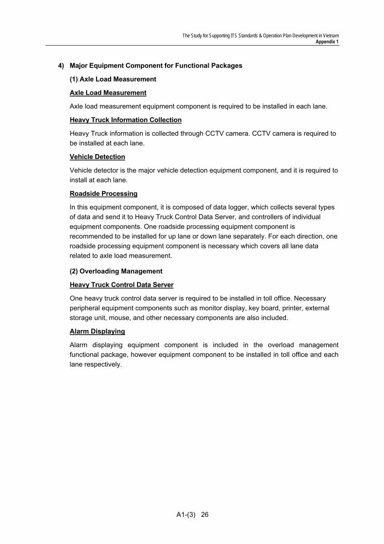
The Study for Supporting ITS Standards & Operation Plan Development in Vietnam Appendix 1
A1-(3) 26
4) Major Equipment Component for Functional Packages
(1) Axle Load Measurement
Axle Load Measurement
Axle load measurement equipment component is required to be installed in each lane.
Heavy Truck Information Collection
Heavy Truck information is collected through CCTV camera. CCTV camera is required to be installed at each lane.
Vehicle Detection
Vehicle detector is the major vehicle detection equipment component, and it is required to install at each lane.
Roadside Processing
In this equipment component, it is composed of data logger, which collects several types of data and send it to Heavy Truck Control Data Server, and controllers of individual equipment components. One roadside processing equipment component is recommended to be installed for up lane or down lane separately. For each direction, one roadside processing equipment component is necessary which covers all lane data related to axle load measurement.
(2) Overloading Management
Heavy Truck Control Data Server
One heavy truck control data server is required to be installed in toll office. Necessary peripheral equipment components such as monitor display, key board, printer, external storage unit, mouse, and other necessary components are also included.
Alarm Displaying
Alarm displaying equipment component is included in the overload management functional package, however equipment component to be installed in toll office and each lane respectively.

The Study for Supporting ITS Standards & Operation Plan Development in Vietnam Appendix 1
A1-(3) 27
11. Preparation for Stepwise Implementation
The solutions for unification of system architecture, basic concept and actualization methods of heavy truck control are discussed in this volume of the Draft Design Standards. Further solutions are to be referred in other volumes as below.
(1) Establishment of connectability of communication network Draft Communication System Plan
(2) Establishment of inter-operability of message/data Draft Message/Data Standards (3) Establishment of compatibility of equipment components Draft General Specifications
Even in the ITS to be implemented in many different expressway sections, consistency among systems can be secured by premising the basic concept shown in the report and by complying with the provisions shown in the Draft ITS Standards. At the same time, the consistency among systems achieves stepwise ITS implementation keeping pace with the expressway construction by section.