draft etsi en 305 550 v2.1 · etsi 6 draft etsi en 305 550 v2.1.0 (2017-10) intellectual property...
TRANSCRIPT

Draft ETSI EN 305 550 V2.1.0 (2017-10)
Short Range Devices (SRD); Radio equipment to be used
in the 40 GHz to 246 GHz frequency range; Harmonised Standard for access to radio spectrum
HARMONISED EUROPEAN STANDARD

ETSI
Draft ETSI EN 305 550 V2.1.0 (2017-10) 2
Reference REN/ERM-TG28-509
Keywords harmonised standard, radio, SRD, testing, UWB
ETSI
650 Route des Lucioles F-06921 Sophia Antipolis Cedex - FRANCE
Tel.: +33 4 92 94 42 00 Fax: +33 4 93 65 47 16
Siret N° 348 623 562 00017 - NAF 742 C
Association à but non lucratif enregistrée à la Sous-Préfecture de Grasse (06) N° 7803/88
Important notice
The present document can be downloaded from: http://www.etsi.org/standards-search
The present document may be made available in electronic versions and/or in print. The content of any electronic and/or print versions of the present document shall not be modified without the prior written authorization of ETSI. In case of any
existing or perceived difference in contents between such versions and/or in print, the only prevailing document is the print of the Portable Document Format (PDF) version kept on a specific network drive within ETSI Secretariat.
Users of the present document should be aware that the document may be subject to revision or change of status. Information on the current status of this and other ETSI documents is available at
https://portal.etsi.org/TB/ETSIDeliverableStatus.aspx
If you find errors in the present document, please send your comment to one of the following services: https://portal.etsi.org/People/CommiteeSupportStaff.aspx
Copyright Notification
No part may be reproduced or utilized in any form or by any means, electronic or mechanical, including photocopying and microfilm except as authorized by written permission of ETSI.
The content of the PDF version shall not be modified without the written authorization of ETSI. The copyright and the foregoing restriction extend to reproduction in all media.
© ETSI 2017.
All rights reserved.
DECTTM, PLUGTESTSTM, UMTSTM and the ETSI logo are trademarks of ETSI registered for the benefit of its Members. 3GPPTM and LTE™ are trademarks of ETSI registered for the benefit of its Members and
of the 3GPP Organizational Partners. oneM2M logo is protected for the benefit of its Members.
GSM® and the GSM logo are trademarks registered and owned by the GSM Association.

ETSI
Draft ETSI EN 305 550 V2.1.0 (2017-10) 3
Contents
Intellectual Property Rights ................................................................................................................................ 6
Foreword ............................................................................................................................................................. 6
Modal verbs terminology .................................................................................................................................... 6
1 Scope ........................................................................................................................................................ 7
2 References ................................................................................................................................................ 7
2.1 Normative references ......................................................................................................................................... 7
2.2 Informative references ........................................................................................................................................ 8
3 Definitions, symbols and abbreviations ................................................................................................... 9
3.1 Definitions .......................................................................................................................................................... 9
3.2 Symbols ............................................................................................................................................................ 10
3.3 Abbreviations ................................................................................................................................................... 10
4 Technical requirements specifications ................................................................................................... 11
4.1 Environmental conditions ................................................................................................................................. 11
4.2 General ............................................................................................................................................................. 11
4.2.1 Background information ............................................................................................................................. 11
4.2.2 Wanted performance criteria....................................................................................................................... 11
4.3 Transmitter Conformance Requirements .......................................................................................................... 12
4.3.1 Permitted range of operating frequencies ................................................................................................... 12
4.3.1.1 Applicability.......................................................................................................................................... 12
4.3.1.2 Description ............................................................................................................................................ 12
4.3.1.3 Limits .................................................................................................................................................... 12
4.3.1.4 Conformance ......................................................................................................................................... 12
4.3.2 Operating frequency range(s) (OFR) .......................................................................................................... 12
4.3.2.1 Applicability.......................................................................................................................................... 12
4.3.2.2 Description ............................................................................................................................................ 12
4.3.2.3 Limits .................................................................................................................................................... 13
4.3.2.4 Conformance ......................................................................................................................................... 13
4.3.3 Mean Power ................................................................................................................................................ 13
4.3.3.1 Applicability.......................................................................................................................................... 13
4.3.3.2 Description ............................................................................................................................................ 14
4.3.3.3 Limits .................................................................................................................................................... 14
4.3.3.4 Conformance ......................................................................................................................................... 14
4.3.4 Mean Power spectral density ...................................................................................................................... 14
4.3.4.1 Applicability.......................................................................................................................................... 14
4.3.4.2 Description ............................................................................................................................................ 14
4.3.4.3 Limits .................................................................................................................................................... 14
4.3.4.4 Conformance ......................................................................................................................................... 15
4.3.5 Unwanted emissions in the out-of-band domain ......................................................................................... 15
4.3.5.1 Applicability.......................................................................................................................................... 15
4.3.5.2 Description ............................................................................................................................................ 15
4.3.5.3 Limits .................................................................................................................................................... 15
4.3.5.4 Conformance ......................................................................................................................................... 16
4.3.6 Unwanted emissions in the spurious domain .............................................................................................. 16
4.3.6.1 Applicability.......................................................................................................................................... 16
4.3.6.2 Description ............................................................................................................................................ 16
4.3.6.3 Limits .................................................................................................................................................... 16
4.3.6.4 Conformance ......................................................................................................................................... 17
4.4 Receiver Conformance Requirements .............................................................................................................. 17
4.4.1 General ........................................................................................................................................................ 17
4.4.2 Receiver spurious emissions ....................................................................................................................... 17
4.4.2.1 Applicability.......................................................................................................................................... 17
4.4.2.2 Description ............................................................................................................................................ 17
4.4.2.3 Limits .................................................................................................................................................... 17
4.4.2.4 Conformance ......................................................................................................................................... 18

ETSI
Draft ETSI EN 305 550 V2.1.0 (2017-10) 4
4.4.3 Receiver interference signal handling ......................................................................................................... 18
4.4.3.1 Applicability.......................................................................................................................................... 18
4.4.3.2 Description ............................................................................................................................................ 18
4.4.3.3 Limits .................................................................................................................................................... 18
4.4.3.4 Conformance ......................................................................................................................................... 19
5 Testing for compliance with technical requirements .............................................................................. 19
5.1 Environmental conditions for testing ............................................................................................................... 19
5.2 General conditions for testing .......................................................................................................................... 19
5.2.1 Product information .................................................................................................................................... 19
5.2.2 Requirements for the test modulation ......................................................................................................... 20
5.2.2.1 Normal test signals and test modulation................................................................................................ 20
5.2.2.2 Normal test signals for data ................................................................................................................... 20
5.2.2.3 Testing of frequency agile or hopping equipment ................................................................................. 20
5.2.3 Test conditions, power supply and ambient temperatures .......................................................................... 20
5.2.4 Choice of equipment for test suites ............................................................................................................. 20
5.2.5 Multiple Operating bandwidths and multiband equipment ......................................................................... 21
5.2.6 Testing of host connected equipment and plug-in radio devices ................................................................ 21
5.2.6.1 General .................................................................................................................................................. 21
5.2.6.2 The use of a host or test fixture for testing plug-In radio devices ......................................................... 21
5.3 Mechanical and electrical design ...................................................................................................................... 21
5.3.1 General ........................................................................................................................................................ 21
5.3.2 Controls ...................................................................................................................................................... 21
5.3.3 Transmitter shut-off facility ........................................................................................................................ 21
5.3.4 Receiver automatic switch-off .................................................................................................................... 21
5.4 Auxiliary test equipment .................................................................................................................................. 22
5.5 Reference bandwidth of the measuring receiver .............................................................................................. 22
5.6 General requirements for RF cables ................................................................................................................. 23
5.7 RF waveguides ................................................................................................................................................. 23
5.8 External harmonic mixers ................................................................................................................................ 24
5.8.1 Introduction................................................................................................................................................. 24
5.8.2 Signal identification .................................................................................................................................... 25
5.8.3 Measurement hints ...................................................................................................................................... 25
5.9 Interpretation of the measurement results ........................................................................................................ 26
5.9.0 General ........................................................................................................................................................ 26
5.9.1 For measurement above 110 GHz ............................................................................................................... 26
5.9.2 Conversion loss data and measurement uncertainty ................................................................................... 27
5.9.3 Measurement uncertainty is equal to or less than maximum acceptable uncertainty .................................. 27
5.9.4 Measurement uncertainty is greater than maximum acceptable uncertainty ............................................... 27
6 Conformance test suits ........................................................................................................................... 28
6.1 Introduction ...................................................................................................................................................... 28
6.2 Initial Measurement steps ................................................................................................................................. 28
6.3 Radiated measurements .................................................................................................................................... 28
6.3.1 General ........................................................................................................................................................ 28
6.3.2 Test sites and general arrangements for measurements involving the use of radiated fields ...................... 28
6.3.3 Guidance on the use of a radiation test site ................................................................................................. 28
6.3.3.1 General .................................................................................................................................................. 28
6.3.3.2 Minimum requirements for test sites for measurements above 18 GHz ............................................... 28
6.3.3.3 Range length. ........................................................................................................................................ 29
6.3.4 Standard test and calibration methods ........................................................................................................ 30
6.4 Test fixture ....................................................................................................................................................... 30
6.4.1 Requirements .............................................................................................................................................. 30
6.4.2 Calibration .................................................................................................................................................. 30
6.5 Conformance methods of measurement for transmitter ................................................................................... 31
6.5.1 General ........................................................................................................................................................ 31
6.5.2 Operating frequency range(s) (OFR) .......................................................................................................... 31
6.5.3 Mean Power ................................................................................................................................................ 31
6.5.4 Mean power spectral density measurements ............................................................................................... 31
6.5.5 Transmitter unwanted emissions ................................................................................................................. 32
6.6 Conformance methods of measurement for receiver ........................................................................................ 32
6.6.1 Receiver spurious emissions ....................................................................................................................... 32

ETSI
Draft ETSI EN 305 550 V2.1.0 (2017-10) 5
6.6.2 Receiver interference signal handling ......................................................................................................... 32
Annex A (informative): Relationship between the present document and the essential requirements of Directive 2014/53/EU ......................................................... 33
Annex B (informative): Measurement antenna, preamplifier, and cable specifications .................. 34
Annex C (informative): Atmospheric absorptions and material dependent attenuations ............... 35
C.0 General ................................................................................................................................................... 35
C.1 Atmospheric absorptions ........................................................................................................................ 35
C.2 Material dependent attenuations ............................................................................................................. 37
Annex D (informative): Bibliography ................................................................................................... 39
Annex E (informative): Change history ............................................................................................... 40
History .............................................................................................................................................................. 41

ETSI
Draft ETSI EN 305 550 V2.1.0 (2017-10) 6
Intellectual Property Rights
Essential patents
IPRs essential or potentially essential to the present document may have been declared to ETSI. The information pertaining to these essential IPRs, if any, is publicly available for ETSI members and non-members, and can be found in ETSI SR 000 314: "Intellectual Property Rights (IPRs); Essential, or potentially Essential, IPRs notified to ETSI in respect of ETSI standards", which is available from the ETSI Secretariat. Latest updates are available on the ETSI Web server (https://ipr.etsi.org/).
Pursuant to the ETSI IPR Policy, no investigation, including IPR searches, has been carried out by ETSI. No guarantee can be given as to the existence of other IPRs not referenced in ETSI SR 000 314 (or the updates on the ETSI Web server) which are, or may be, or may become, essential to the present document.
Trademarks
The present document may include trademarks and/or tradenames which are asserted and/or registered by their owners. ETSI claims no ownership of these except for any which are indicated as being the property of ETSI, and conveys no right to use or reproduce any trademark and/or tradename. Mention of those trademarks in the present document does not constitute an endorsement by ETSI of products, services or organizations associated with those trademarks.
Foreword This draft Harmonised European Standard (EN) has been produced by ETSI Technical Committee Electromagnetic compatibility and Radio spectrum Matters (ERM), and is now submitted for the combined Public Enquiry and Vote phase of the ETSI standards EN Approval Procedure.
The present document has been prepared under the Commission's standardisation request C(2015) 5376 final [i.10] to provide one voluntary means of conforming to the essential requirements of Directive 2014/53/EU on the harmonisation of the laws of the Member States relating to the making available on the market of radio equipment and repealing Directive 1999/5/EC [i.9].
Once the present document is cited in the Official Journal of the European Union under that Directive, compliance with the normative clauses of the present document given in table A.1 confers, within the limits of the scope of the present document, a presumption of conformity with the corresponding essential requirements of that Directive, and associated EFTA regulations.
The present document is covering Short Range Devices (SRD) Radio equipment to be used in the 40 GHz to 246 GHz frequency range.
Proposed national transposition dates
Date of latest announcement of this EN (doa): 3 months after ETSI publication
Date of latest publication of new National Standard or endorsement of this EN (dop/e):
6 months after doa
Date of withdrawal of any conflicting National Standard (dow): 18 months after doa
Modal verbs terminology In the present document "shall", "shall not", "should", "should not", "may", "need not", "will", "will not", "can" and "cannot" are to be interpreted as described in clause 3.2 of the ETSI Drafting Rules (Verbal forms for the expression of provisions).
"must" and "must not" are NOT allowed in ETSI deliverables except when used in direct citation.

ETSI
Draft ETSI EN 305 550 V2.1.0 (2017-10) 7
1 Scope The present document specifies technical characteristics and methods of measurements for Non-specific Short Range Devices category equipment types.
Non specific SRDs category is defined by the EU Commission Decision 2013/752/EU [i.2] as:
• "The non-specific short-range device category covers all kinds of radio devices, regardless of the application or the purpose, which fulfil the technical conditions as specified for a given frequency band. Typical uses include telemetry, telecommand, alarms, data transmissions in general and other applications".
The present document covers equipment:
• capable of operating in frequency bands listed in table 1;
• intended for fixed, mobile or nomadic use;
• either with a Radio Frequency (RF) output connection and dedicated antenna or with an integral antenna;
• with all types of modulation.
Table 1: Short Range Devices within the 40 GHz to 246 GHz frequency range
Frequency Bands (Transmit and Receive)
Applications
57 GHz to 64 GHz Non-specific SRD 61,0 GHz to 61,5 GHz Non-specific SRD 122 GHz to 123 GHz Non-specific SRD 244 GHz to 246 GHz Non-specific SRD
NOTE 1: The frequency usage conditions for Non-specific SRDs are EU wide harmonised bands according to EC Decision 2013/752/EU [i.2] as known at the date of publication of the present document. In addition, it should be noted that other frequency bands may be available for short range devices in a country within the frequency range 40 GHz to 246 GHz covered by the present document. See the CEPT/ERC Recommendation 70-03 [i.1] or as implemented through National Radio Interfaces (NRI) and additional
NOTE 2: The relationship between the present document and essential requirements of article 3.2 of Directive 2014/53/EU [i.9] is given in annex A.
2 References
2.1 Normative references References are specific, identified by date of publication and/or edition number or version number. Only the cited version applies.
Referenced documents which are not found to be publicly available in the expected location might be found at https://docbox.etsi.org/Reference/.
NOTE: While any hyperlinks included in this clause were valid at the time of publication, ETSI cannot guarantee their long term validity.
The following referenced documents are necessary for the application of the present document.
[1] CISPR 16-1-1:2015: "Specification for radio disturbance and immunity measuring apparatus and methods; Part 1-1: Radio disturbance and immunity measuring apparatus - Measuring apparatus".
[2] Recommendation ITU-T O.153 (1992): "Basic parameters for the measurement of error performance at bit rates below the primary rate".

ETSI
Draft ETSI EN 305 550 V2.1.0 (2017-10) 8
[3] ETSI TS 103 052 (V1.1.1) (03-2011): "Electromagnetic compatibility and Radio spectrum Matters (ERM); Radiated measurement methods and general arrangements for test sites up to 100 GHz".
[4] ETSI EN 303 396 (V1.1.1) (12-2016): "Short Range Devices; Measurement Techniques for Automotive and Surveillance Radar Equipment".
[5] ETSI TS 103 361 (V1.1.1) (03-2016): "Short Range Devices (SRD) using Ultra Wide Band technology (UWB); Receiver technical requirements, parameters and measurement procedures to fulfil the requirements of the Directive 2014/53/EU".
[6] Recommendation ITU T O.41 (1994): "Psophometer for use on telephone-type circuits".
[7] CISPR 16-1-4:2010: "Specification for radio disturbance and immunity measuring apparatus and methods; Part 1-4: Radio disturbance and immunity measuring apparatus - Antennas and test sites for radiated disturbance measurements".
[8] CISPR 16-1-5:2014: "Specification for radio disturbance and immunity measuring apparatus and methods; Part 1-5: Radio disturbance and immunity measuring apparatus - Antenna calibration sites and reference test sites for 5 MHz to 18 GHz".
2.2 Informative references References are either specific (identified by date of publication and/or edition number or version number) or non-specific. For specific references, only the cited version applies. For non-specific references, the latest version of the referenced document (including any amendments) applies.
NOTE: While any hyperlinks included in this clause were valid at the time of publication, ETSI cannot guarantee their long term validity.
The following referenced documents are not necessary for the application of the present document but they assist the user with regard to a particular subject area.
[i.1] CEPT/ERC Recommendation 70-03: "Relating to the use of Short Range Devices (SRD)".
[i.2] European Commission Decision 2013/752/EU of 11 December 2013 (amending Decision 2006/771/EC on harmonisation of the radio spectrum for use by short-range devices and repealing Decision 2005/928/EC).
[i.3] CEPT/ERC Recommendation 74-01: "Unwanted emissions in the spurious domain", Hradec Kralove, Cardiff 2011.
[i.4] Recommendation ITU-R P.676-5 (2001): "Attenuation by atmospheric gases".
[i.5] IEC 60153: "Hollow metallic waveguides".
[i.6] ETSI TR 102 215: "Electromagnetic compatibility and Radio spectrum Matters (ERM); Recommended approach, and possible limits for measurement uncertainty for the measurement of radiated electromagnetic fields above 1 GHz".
[i.7] ETSI TR 102 273 (V1.2.1) (all parts): "Electromagnetic compatibility and Radio spectrum Matters (ERM); Improvement on Radiated Methods of Measurement (using test site) and evaluation of the corresponding measurement uncertainties".
[i.8] ETSI TR 100 028 (V1.4.1) (all parts): "Electromagnetic compatibility and Radio spectrum Matters (ERM); Uncertainties in the measurement of mobile radio equipment characteristics".
[i.9] Directive 2014/53/EU of the European Parliament and of the Council of 16 April 2014 on the harmonisation of the laws of the Member States relating to the making available on the market of radio equipment and repealing Directive 1999/5/EC.
[i.10] Commission Implementing Decision C(2015) 5376 final of 4.8.2015 on a standardisation request to the European Committee for Electrotechnical Standardisation and to the European Telecommunications Standards Institute as regards radio equipment in support of Directive 2014/53/EU of the European Parliament and of the Council.

ETSI
Draft ETSI EN 305 550 V2.1.0 (2017-10) 9
3 Definitions, symbols and abbreviations
3.1 Definitions For the purposes of the present document, the following terms and definitions apply:
alarm: use of radio communication for indicating an alarm condition at a distant location
artificial antenna: non-radiating dummy load equal to the nominal impedance specified by the manufacturer
assigned frequency band: frequency band within which the device is authorized to operate and to perform the intended function of the equipment
dedicated antenna: removable antenna supplied and tested with the radio equipment, designed as an indispensable part of the equipment
Direct Sequence Spread Spectrum (DSSS): form of modulation where a combination of data to be transmitted and a fixed code sequence (chip sequence) is used to directly modulate a carrier, e.g. by phase shift keying
NOTE: The code rate determines the occupied bandwidth.
environmental profile: range of environmental conditions under which equipment within the scope of the present document is required to comply with the provisions of the present document
fixed station: equipment intended for use in a fixed location
Frequency Hopping Spread Spectrum (FHSS): spread spectrum technique in which the transmitter signal occupies a number of frequencies in time, each for some period of time, referred to as the dwell time
NOTE: Transmitter and receiver follow the same frequency hop pattern. The number of hop positions and the bandwidth per hop position determine the occupied bandwidth.
integral antenna: permanent fixed antenna, which may be built-in, designed as an indispensable part of the equipment
mobile station: equipment normally fixed in a vehicle or used as a transportable station
necessary bandwidth: width of the emitted frequency band which is just sufficient to ensure the transmission of information at the rate and with the quality required under specified conditions
NOTE: The necessary bandwidth including the frequency tolerances is accommodated within the assigned frequency band.
Occupied Bandwidth (OBW): width of a frequency band such that, below the lower and above the upper frequency limits, the mean powers emitted are each equal to 0,5 % of the total mean power of a given emission
NOTE: This corresponds to the -23 dBc bandwidth of the signal.
operating frequency: nominal frequency at which equipment is operated; this is also referred to as the operating centre frequency
NOTE: Equipment may be able to operate at more than one operating frequency.
operating frequency range: range of operating frequencies over which the equipment can be adjusted through tuning, switching or reprogramming
portable station: equipment intended to be carried, attached or implanted
Power Spectral Density (PSD): ratio of the amount of power to the used radio measurement bandwidth
NOTE: It is expressed in units of dBm/Hz or as a power in unit dBm with respect to the used bandwidth. In case of measurement with a spectrum analyser the measurement bandwidth is equal to the RBW.
radiated measurements: measurements which involve the absolute measurement of a radiated field

ETSI
Draft ETSI EN 305 550 V2.1.0 (2017-10) 10
spread spectrum: modulation technique in which the energy of a transmitted signal is spread throughout a large portion of the frequency spectrum
ultra low power equipment: equipment using transmit envelope power below the receiver and idle/standby transmitter limits given in CEPT/ERC Recommendation 74-01 [i.3], see table 8
unwanted emissions: emission on a frequency or frequencies which are outside the necessary bandwidth and the level of which may be reduced without affecting the corresponding transmission of information
NOTE: Unwanted emissions include harmonic emissions, parasitic emissions, intermodulation products and frequency conversion products.
3.2 Symbols For the purposes of the present document, the following symbols apply:
Dant Aperture dimension of the radiating antenna dB deciBel dBi gain in deciBels relative to an isotropic antenna E Electrical field strength Eo Reference electrical field strength
NOTE: See annex B.
f Frequency P Power R Distance Ro Reference distance
NOTE: See annex B.
t Time λ wavelength
3.3 Abbreviations For the purposes of the present document, the following abbreviations apply:
CEPT European Conference of Postal and Telecommunications administrations CISPR Comité International Spécial des Perturbations Radioélectriques DC Direct Current DSSS Direct Sequence Spread Spectrum e.i.r.p. equivalent isotropical radiated power ECC Electronic Communications Committee EESS Earth Exploration Satellite Service EIA Electronic Industries Alliance EIRP Equivalent Isotropic Radiated Power EMC Electro Magnetic Compatibility emf electromagnetic field ERC European Radiocommunication Committee EUT Equipment Under Test FAR Fully Anechoic Rooms FH Frequency Hopping FHSS Frequency Hopping Spread Spectrum FMCW Frequency Modulated Continuous-Wave radar FSK Frequency Shift Keying FSL Free Space Loss IF Intermediate Frequency ITU-R International Telecommunications Union, Radio sector ITU-T International Telecommunications Union, Telecommunications sector LNA Low Noise Amplifier

ETSI
Draft ETSI EN 305 550 V2.1.0 (2017-10) 11
LO Local Oscillator NF Noise Figure NRI National Radio Interfaces OBW Occupied BandWidth OFR Operating Frequency Range OOB Out-of-Band PCORR Power correcting PRF Pulse Repetition Frequency PSD Power Spectral Density R&TTE Radio and Telecommunications Terminal Equipment RBW Resolution BandWidth RBWREF measuring receiver resolution bandwidth RCS Radar Cross Section RCSC Radio Components Standardization Committee RF Radio Frequency RMS Root Mean Square RX Receiver SMA SubMiniature version A - connector SND/ND Signal + Noise + Distortion / Noise + Distortion SRD Short Range Device TX Transmitter UWB Ultra WideBand VSWR Voltage Standing Wave Ratio
4 Technical requirements specifications
4.1 Environmental conditions The technical requirements of the present document apply under the environmental profile for operation of the equipment, which shall be declared by the manufacturer. The equipment shall comply with all the technical requirements of the present document which are identified as applicable in annex A at all times when operating within the boundary limits of the declared operational environmental profile. The normal and extreme test conditions are defined in clauses 4.4.3 and 4.4.4 of ETSI EN 303 396 [4].
4.2 General
4.2.1 Background information
In this clause general considerations for the testing of EUT in the frequency range listed in table 1 are given. The tests cover integrated transceivers and separate transmit/receive modules.
All operating bandwidths of the equipment shall be declared by the equipment manufacturer (see clause 4.3.1).
Where equipment has more than one operating bandwidths, sufficient number of operating bandwidths shall be chosen for testing so as to encompass the lower and higher limits of the operating frequency and the minimum and maximum bandwidth.
4.2.2 Wanted performance criteria
For the purpose of the receiver performance tests, the criterion that the EUT shall indicate the properties of a given scenario for which the EUT was forseen to operate, e.g. target at a given distance or other possible use-cases as described in ETSI TS 103 361 [5]. Since EUT considered here typically are tailored to specific applications, no single wanted performance criterion can be defined here.

ETSI
Draft ETSI EN 305 550 V2.1.0 (2017-10) 12
Therefore the EUT/receiver shall produce an appropriate output under normal conditions.
Examples for a wanted performance criteria as indicated below:
• a SND/ND ratio of 20 dB, measured at the receiver output through a telephone psophometric weighting network as described in Recommendation ITU-T O.41 [6]; or
• after demodulation, a data signal with a bit error ratio of 10-2 without correction (as described in Recommendation ITU-T O.153 [2]); or
• after demodulation, a message acceptance ratio of 80 % (as described in Recommendation ITU-T O.153 [2]); or
• an appropriate false alarm rate or sensing criteria as declared by the manufacturer;
• some performance criteria and test cases are defined in clauses 9.2.1 and 9.4 of ETSI TS 103 361 [5].
For the performance criteria of radio determination the manufacturer shall declare:
• the relevant use-case properties (e.g. presence, range, relative speed, azimuth angle, datarate, etc.) of the sensing scenario;
• the related radio parameter of the scenario, like type and RCS of the target and the distance.
4.3 Transmitter Conformance Requirements
4.3.1 Permitted range of operating frequencies
4.3.1.1 Applicability
This requirement shall apply to all transmitting EUT.
4.3.1.2 Description
The permitted range of operating frequencies is the frequency range over which the equipment is authorized to operate.
4.3.1.3 Limits
The permitted range of operating frequency for intentional emissions shall be within one of the frequency ranges from table 1.
Outside the permitted range of operating frequencies the unintentional emissions shall be reduced to the limits given in clauses 4.3.5 and 4.3.6.
4.3.1.4 Conformance
The manufacturer shall declare the permitted range of operating frequencies. The justification/test shall be performed for Operating frequency ranges, see clause 4.3.2.
4.3.2 Operating frequency range(s) (OFR)
4.3.2.1 Applicability
This requirement shall apply to all transmitting EUT.
4.3.2.2 Description
The operating frequency range is the frequency range over which the EUT is intentionally transmitting.

ETSI
Draft ETSI EN 305 550 V2.1.0 (2017-10) 13
The operating frequency range(s) are determined by the lowest (fL) and highest frequency (fH) as occupied by the power envelope.
The EUT could have more than one operating frequency range.
For a single frequency systems the OFR is equal to the occupied bandwidth (OBW) of the EUT.
For multi-frequency systems the OFR is described in figure 1.
Figure 1: OFR of a multi – frequency system
4.3.2.3 Limits
The upper (fH) and lower (fL) limits of the operating frequency range shall meet the conditions in table 2.
Table 2: Limits for fH and fL [i.9]
fL fH
57 GHz to 64 GHz ≥ 57 GHz ≤ 64 GHz 61,0 GHz to 61,5 GHz ≥ 61,0 GHz ≤ 61,5 GHz 122 GHz to 123 GHz ≥ 122 GHz ≤ 123 GHz 244 GHz to 246 GHz ≥ 244 GHz ≤ 246 GHz NOTE: If the device can work in different modes and different frequency ranges these frequencies should be
reported for each mode and frequency range.
4.3.2.4 Conformance
The conformance test suite for maximum value of the operating frequency range(s) shall be as defined in clause 6.5.2.
If the operating frequency range cannot be measured it shall be declared by the manufacturer.
Conformance shall be established under normal test conditions, see clause 4.1.
The interpretation of the results for the measurements uncertainty shall be as given in clause 5.9.
4.3.3 Mean Power
4.3.3.1 Applicability
This requirement shall apply to all transmitting EUT.

ETSI
Draft ETSI EN 305 550 V2.1.0 (2017-10) 14
4.3.3.2 Description
The radiated power is the mean Equivalent Isotropic Radiated Power (EIRP) for the equipment during a transmission burst. The mean e.i.r.p. refers to the highest power level of the transmitter power control range during the transmission cycle if the transmitter power control is implemented.
4.3.3.3 Limits
The radiated output power is applicable to the system as a whole when operated at the highest stated power level. For a smart antenna system and directional antennas, the limit applies to the configuration which results in the highest EIRP.
The radiated output power in normal wideband operation shall be limited by usage as indicated in table 3.
Table 3: RF output power limit [i.1]
Frequency Bands RF output power Application Notes
57 GHz to 64 GHz 100 mW e.i.r.p / 20 dBm e.i.r.p. Non-specific SRD Note
61,0 GHz to 61,5 GHz 100 mW e.i.r.p./ 20 dBm e.i.r.p. Non-specific SRD
122 GHz to 122,25 GHz 10 dBm e.i.r.p Non-specific SRD 10 dBm within 250 MHz
122,25 GHz to 123 GHz 100 mW e.i.r.p./ 20 dBm e.i.r.p. Non-specific SRD
244 GHz to 246 GHz 100 mW e.i.r.p./ 20 dBm e.i.r.p. Non-specific SRD
NOTE: A max transmitter output power of 10 dBm.
4.3.3.4 Conformance
The conformance test suite for maximum value of mean power shall be as defined in clause 6.5.3.
Conformance shall be established under normal test conditions, see clause 4.1.
The interpretation of the results for the measurements uncertainty shall be as given in clause 5.9.
4.3.4 Mean Power spectral density
4.3.4.1 Applicability
This requirement shall apply to all transmitting EUT.
4.3.4.2 Description
The mean power spectral density (e.i.r.p.) is defined as the emitted power spectral density over a defined bandwidth of the transmitter including antenna gain radiated in the direction of the maximum level under the specified conditions of measurement.
4.3.4.3 Limits
The maximum mean power spectral density is applicable to the EUT as a whole when operated at the highest stated power level. The limits are given in table 4.

ETSI
Draft ETSI EN 305 550 V2.1.0 (2017-10) 15
Table 4: Mean Power Spectral Density Limit (PSD) (e.i.r.p) [i.1]
Frequency Bands Power Spectral Density Application Notes 57 GHz to 64 GHz 13 dBm/MHz e.i.r.p. Non-specific SRD 61,0 GHz to 61,5 GHz No limit defined Non-specific SRD
122 GHz to 122,25 GHz -48 dBm/MHz > 30° elevation Non-specific SRD Notes 1, 2 and 3
122,25 GHz to 123 GHz No limit defined Non-specific SRD 244 GHz to 246 GHz No limit defined Non-specific SRD NOTE 1: These limits should be measured with an rms detector and an averaging time of 1 ms or less. NOTE 2: The limit of -48 dBm/MHz applies for the normal operation mode of handheld and mobile devices
and for fixed installation. NOTE 3: See for declaration requirements, clause 5.2.
4.3.4.4 Conformance
The conformance tests for Mean Power spectral density shall be as defined in clause 6.5.4.
Conformance shall be established under normal test conditions, see clause 4.1.
The interpretation of the results for the measurements uncertainty shall be as given in clause 5.9.
4.3.5 Unwanted emissions in the out-of-band domain
4.3.5.1 Applicability
This requirement applies to all EUT.
4.3.5.2 Description
The transmitter out-of-band emissions for a single frequency system are to be considered in frequency ranges defined in figure 2.
Figure 2: Emissions in the out-of-band and spurious domain
4.3.5.3 Limits
The RMS mean power spectral density radiated in the calculated out-of-band domain (between fSL to fL and fH to fSH band) shall not be greater than the values given in table 6.

ETSI
Draft ETSI EN 305 550 V2.1.0 (2017-10) 16
An additional requirement introduced: if the calculated fSL/fSH will be theoretical below or above the frequency which came out of the calculation based on 250 % of the maximum allowed OBW (see table 2). Therefore the border between OOB / spurious will be fixed at the frequencies in table 5 (normal 250 % rule based on the Centre frequency of the signal).
Table 5: Limits for the max. fSL and fSH frequency, based on the max. theoretical OBW of the EUT
Frequency Bands Centre frequency Max OBW fSL fSH
57 GHz to 64 GHz 60,5 GHz 7 GHz 43 GHz 78 GHz 61,0 GHz to 61,5 GHz 61,25 GHz 500 MHz 60 GHz 62,5 GHz 122 GHz to 123 GHz 122,5 GHz 1 GHz 120 GHz 125 GHz 244 GHz to 246 GHz 245 GHz 2 GHz 240 GHz 250 GHz
Table 6: Out-of-band domain
Frequency [GHz] rms power density [dBm/MHz] fSL ≤ f < fL See table 7
fH < f ≤ fSH See table 7
Table 7: Limits for out-of-band radiation
Frequency Bands OOB limit [dBm/MHz] 57 GHz to 64 GHz -20 dBm/MHz
61,0 GHz to 61,5 GHz -10 dBm/MHz 122 GHz to 123 GHz -10 dBm/MHz 244 GHz to 246 GHz -15 dBm/MHz
The values fL and fH are the results of the operating frequency range conformance test, see clause 4.3.2.4.
4.3.5.4 Conformance
The conformance test suite for unwanted emissions in the out-of-band domain shall be as defined in clause 6.5.5.
Conformance shall be established under normal test conditions defined in clause 4.1.
The interpretation of the results for the measurements uncertainty shall be as given in clause 5.9.
4.3.6 Unwanted emissions in the spurious domain
4.3.6.1 Applicability
This requirement applies to all EUT.
4.3.6.2 Description
The transmitter spurious emissions for a single frequency system are to be considered in frequency ranges defined in figure 2.
4.3.6.3 Limits
The effective radiated power of any radiated spurious emission shall be not greater than the values given in table 8.

ETSI
Draft ETSI EN 305 550 V2.1.0 (2017-10) 17
Table 8: Limits of radiated spurious emissions [i.3]
Frequency range (MHz) Limit values for spurious radiation Detector type 47 to 74 -54 dBm e.r.p. Quasi-Peak
87,5 to 118 -54 dBm e.r.p. Quasi-Peak 174 to 230 -54 dBm e.r.p. Quasi-Peak 470 to 862 -54 dBm e.r.p. Quasi-Peak
otherwise in band 30 to 1 000 -36 dBm e.r.p. Quasi-Peak f > 1 000 to 300 000 (note) -30 dBm e.i.r.p. RMS
NOTE: According to CEPT/ERC/REC 74-01 [i.3], spurious emission is measured up to the 2nd harmonic of the
fundamental frequency.
4.3.6.4 Conformance
The conformance test suite for unwanted emissions in the spurious domain shall be as defined in clause 6.5.5.
Conformance shall be established under normal test conditions defined in clause 4.1.
The interpretation of the results for the measurements uncertainty shall be as given in clause 5.9.
4.4 Receiver Conformance Requirements
4.4.1 General
For a detailed description of related receiver requirements see ETSI TS 103 361 [5].
4.4.2 Receiver spurious emissions
4.4.2.1 Applicability
Receiver spurious emission testing shall apply only when the equipment can work in a receive-only mode or is a receive-only device.
NOTE: Otherwise receiver spurious emissions are measured as part of the transmitter spurious emissions, see clause 4.3.6.
4.4.2.2 Description
Receiver spurious emissions are emissions at any frequency when the equipment is in receive mode.
4.4.2.3 Limits
The narrowband spurious emissions of the receiver shall not exceed the values in table 9 in the indicated bands (see CEPT/ERC/REC 74-01 [i.3]).
Table 9: Narrowband spurious emission limits for receivers
Frequency range Limit 30 MHz to 1 GHz -57 dBm (e.r.p.)
above 1 GHz to 40 GHz -47 dBm (e.i.r.p.)
The above limit values apply to narrowband emissions, e.g. as caused by local oscillator leakage.
Wideband spurious emissions shall not exceed the values given in table 10.

ETSI
Draft ETSI EN 305 550 V2.1.0 (2017-10) 18
Table 10: Wideband spurious emission limits for receivers
Frequency range Limit 30 MHz to 1 GHz -47 dBm/MHz (e.r.p.)
above 1 GHz to 40 GHz -37 dBm/MHz (e.i.r.p.)
4.4.2.4 Conformance
The conformance test suite for receiver spurious emissions shall be as defined in clause 6.6.1.
Conformance shall be established under normal test conditions, see clause 4.1.
The interpretation of the results for the measurements uncertainty shall be as given in clause 5.9.
4.4.3 Receiver interference signal handling
4.4.3.1 Applicability
This requirement shall apply to all receiving EUT.
4.4.3.2 Description
Interferer signal handling, defined as the capability of the device to operate as intended in coexistence with interferers, is a receiver parameter for radio applications.
Operation as intended is evaluated using a performance criterion, see clause 4.2.2.
4.4.3.3 Limits
The EUT shall achieve the wanted performance criterion, see clause 4.2.2, in the presence of the below defined interfering signals.
The interfering signal transmitter shall transmit continuous wave signals at specific frequencies, as described in table 11 to table 14.
Table 11: For EUT operating within 57 GHz to 64 GHz
In-band signal OOB signal Remote-band signal Frequency Centre frequency (fc) of the
EUT modulated signal (see clause 4.3.1)
f = fc ± OBW f = fc ± 10 × OBW
Signal level field strength at the EUT
55 mV/m 173 mV/m 173 mV/m
Equivalent EIRP at 10 m 10 dBm 20 dBm 20 dBm
Table 12: For EUT operating within 61,0 GHz to 61,5 GHz
In-band signal OOB signal Remote-band signal Frequency Centre frequency (fc) of the
EUT modulated signal (see clause 4.3.1)
f = fc ± OBW f = fc ± 10 × OBW
Signal level field strength at the EUT
55 mV/m 173 mV/m 173 mV/m
Equivalent EIRP at 10 m 10 dBm 20 dBm 20 dBm

ETSI
Draft ETSI EN 305 550 V2.1.0 (2017-10) 19
Table 13: For EUT operating within 122 GHz to 123 GHz
In-band signal OOB signal Remote-band signal Frequency Centre frequency (fc) of the
EUT modulated signal (see clause 4.3.1)
f = fc ± OBW f = fc ± 10 × OBW
Signal level field strength at the EUT
55 mV/m 173 mV/m 173 mV/m
Equivalent EIRP at 10 m 10 dBm 20 dBm 20 dBm
Table 14: For EUT operating within 244 GHz to 246 GHz
In-band signal OOB signal Remote-band signal Frequency Centre frequency (fc) of the
EUT modulated signal (see clause 4.3.1)
f = fc ± OBW f = fc ± 10 × OBW
Signal level field strength at the EUT
55 mV/m 173 mV/m 173 mV/m
Equivalent EIRP at 10 m 10 dBm 20 dBm 20 dBm
4.4.3.4 Conformance
The conformance test suite for receiver interference handling shall be as defined in clause 6.6.2.
Conformance shall be established under normal test conditions, see clause 4.1.
The interpretation of the results for the measurements uncertainty shall be as given in clause 5.9.
5 Testing for compliance with technical requirements
5.1 Environmental conditions for testing Tests defined in the present document shall be carried out at one or more representative point(s) within the boundary limits of the declared operational environmental profile.
Where technical performance varies subject to environmental conditions, tests shall be carried out under a sufficient variety of environmental conditions (within the boundary limits of the declared operational environmental profile) to give confidence of compliance for the affected technical requirements.
5.2 General conditions for testing
5.2.1 Product information
The following information shall be stated by the manufacturer in order to carry out the test suites and/or to declare compliance to technical requirements for which no conformance test is included in the present document:
a) The channel plan(s), being the centre frequencies that the EUT is capable of tuning. If the equipment is capable of supporting multiple channel plans in the course of normal operation (e.g. offering different sizes of normal wideband operation), each distinct channel plan and its related occupied bandwidth for normal wideband operation shall be stated.
b) The test modulation(s) used by the EUT.
c) The medium access protocol(s) used by the EUT.
d) The integral antenna design used by the equipment and measures to prevent the user from connecting a different antenna.
ETSI
Draft ETSI EN 305 550 V2.1.0 (2017-10) 20
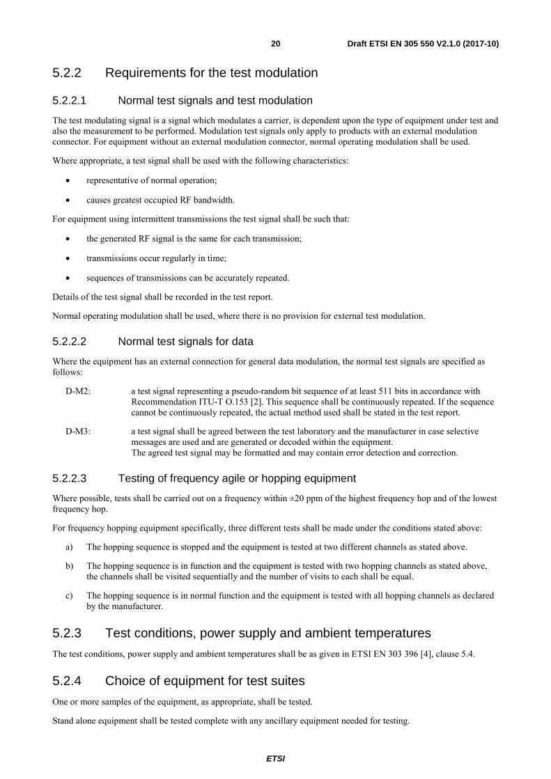
5.2.2 Requirements for the test modulation
5.2.2.1 Normal test signals and test modulation
The test modulating signal is a signal which modulates a carrier, is dependent upon the type of equipment under test and also the measurement to be performed. Modulation test signals only apply to products with an external modulation connector. For equipment without an external modulation connector, normal operating modulation shall be used.
Where appropriate, a test signal shall be used with the following characteristics:
• representative of normal operation;
• causes greatest occupied RF bandwidth.
For equipment using intermittent transmissions the test signal shall be such that:
• the generated RF signal is the same for each transmission;
• transmissions occur regularly in time;
• sequences of transmissions can be accurately repeated.
Details of the test signal shall be recorded in the test report.
Normal operating modulation shall be used, where there is no provision for external test modulation.
5.2.2.2 Normal test signals for data
Where the equipment has an external connection for general data modulation, the normal test signals are specified as follows:
D-M2: a test signal representing a pseudo-random bit sequence of at least 511 bits in accordance with Recommendation ITU-T O.153 [2]. This sequence shall be continuously repeated. If the sequence cannot be continuously repeated, the actual method used shall be stated in the test report.
D-M3: a test signal shall be agreed between the test laboratory and the manufacturer in case selective messages are used and are generated or decoded within the equipment. The agreed test signal may be formatted and may contain error detection and correction.
5.2.2.3 Testing of frequency agile or hopping equipment
Where possible, tests shall be carried out on a frequency within ±20 ppm of the highest frequency hop and of the lowest frequency hop.
For frequency hopping equipment specifically, three different tests shall be made under the conditions stated above:
a) The hopping sequence is stopped and the equipment is tested at two different channels as stated above.
b) The hopping sequence is in function and the equipment is tested with two hopping channels as stated above, the channels shall be visited sequentially and the number of visits to each shall be equal.
c) The hopping sequence is in normal function and the equipment is tested with all hopping channels as declared by the manufacturer.
5.2.3 Test conditions, power supply and ambient temperatures
The test conditions, power supply and ambient temperatures shall be as given in ETSI EN 303 396 [4], clause 5.4.
5.2.4 Choice of equipment for test suites
One or more samples of the equipment, as appropriate, shall be tested.
Stand alone equipment shall be tested complete with any ancillary equipment needed for testing.

ETSI
Draft ETSI EN 305 550 V2.1.0 (2017-10) 21
If equipment has several optional features, considered not to affect the RF parameters then the tests need only to be performed on the equipment configured with that combination of features considered to be the most complex.
5.2.5 Multiple Operating bandwidths and multiband equipment
Where equipment has more than one operating bandwidth, a minimum of two operating bandwidths shall be chosen such that the lower and higher limits of the operating range(s) of the equipment are covered (see clause 4.3.2). All operating bandwidth of the equipment shall be declared by the equipment manufacturer.
In case of multiband equipment, the lowest and highest channel in operation of each band shall be tested.
5.2.6 Testing of host connected equipment and plug-in radio devices
5.2.6.1 General
For combined equipment and for radio parts for which connection to or integration with host equipment is required to offer functionality to the radio, different alternative test approaches are permitted. Where more than one such combination is intended, testing shall not be repeated for combinations of the radio part and various host equipment where the latter are substantially similar.
Where more than one such combination is intended and the combinations are substantially dissimilar, one combination shall be tested against all requirements of the present document and all other combinations shall be tested separately for radiated spurious emissions only.
5.2.6.2 The use of a host or test fixture for testing plug-In radio devices
Where the radio part is a plug-in radio device which is intended to be used within a variety of combinations, a suitable test configuration consisting of either a test fixture or typical host equipment shall be used. This shall be representative for the range of combinations in which the radio device may be used. The test fixture shall allow the radio equipment part to be powered and stimulated as if connected to or inserted into the host or combined equipment. Measurements shall be made to all requirements given in the relevant harmonised standards.
5.3 Mechanical and electrical design
5.3.1 General
The equipment tested shall be designed, constructed and manufactured in accordance with good engineering practice and with the aim of minimizing harmful interference to other equipment and services.
Transmitters and receivers may be individual or combination units.
5.3.2 Controls
Those controls which, if maladjusted, might increase the interfering potentialities of the equipment shall not be easily accessible to the user.
5.3.3 Transmitter shut-off facility
If the transmitter is equipped with an automatic transmitter shut-off facility, it should be made inoperative for the duration of the test. In the case this not possible, a proper test method shall be described and documented.
5.3.4 Receiver automatic switch-off
If the receiver is equipped with a battery-saving circuit for automatic switch-off, this circuit shall be made inoperative for the duration of the tests. In the case this is not possible, a proper test method shall be described and documented.
ETSI
Draft ETSI EN 305 550 V2.1.0 (2017-10) 22
5.4 Auxiliary test equipment All necessary test signal sources and set-up information shall accompany the equipment when it is submitted for testing.
The following product information shall be provided by the manufacturer:
• the type of modulation technology implemented in the equipment (e.g. FMCW or pulsed);
• the operating frequency range(s) of the equipment;
• the intended combination of the transmitter/transceiver and its antenna and their corresponding e.i.r.p. levels in the main beam;
• the nominal power supply voltages of the radio equipment;
• for FMCW, FH, FSK or similar carrier based modulation schemes, it is important to describe the modulation parameters in order to ensure that the right settings of the measuring receiver are used. Important parameters are the modulation period, deviation or dwell times within a modulation period, rate of modulation (Hz/s);
• the implementation of features such as gating, hopping or stepped frequency hopping;
• the implementation of any mitigation techniques such as duty cycle;
• for pulsed equipment, the Pulse Repetition Frequency (PRF) is to be stated.
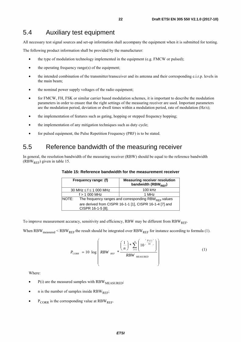
5.5 Reference bandwidth of the measuring receiver In general, the resolution bandwidth of the measuring receiver (RBW) should be equal to the reference bandwidth (RBWREF) given in table 15.
Table 15: Reference bandwidth for the measurement receiver
Frequency range: (f) Measuring receiver resolution bandwidth (RBWREF)
30 MHz ≤ f ≤ 1 000 MHz 100 kHz f > 1 000 MHz 1 MHz
NOTE: The frequency ranges and corresponding RBWREF values
are derived from CISPR 16-1-1 [1], CISPR 16-1-4 [7] and CISPR 16-1-5 [8].
To improve measurement accuracy, sensitivity and efficiency, RBW may be different from RBWREF.
When RBWmeasured < RBWREF the result should be integrated over RBWREF for instance according to formula (1).
⎟⎟⎟⎟⎟⎟
⎠
⎞
⎜⎜⎜⎜⎜⎜
⎝
⎛
⎟⎟
⎠
⎞
⎜⎜
⎝
⎛⎟⎠
⎞⎜⎝
⎛
=∑
=
⎟⎠
⎞⎜⎝
⎛
MEASURED
n
i
iP
REFCORR RBW
nRBWP
1
10)(
10*1
*log10 (1)
Where:
• P(i) are the measured samples with RBWMEASURED;
• n is the number of samples inside RBWREF;
• PCORR is the corresponding value at RBWREF.

ETSI
Draft ETSI EN 305 550 V2.1.0 (2017-10) 23
When RBWmeasured > RBWREF the result for broadband emissions should be normalized to the bandwidth Ratio according to formula (2).
MEASUREDMEASUREDCORR RBW
RBWrefPP log10+=
(2)
Where:
• PMEASURED is the measured value at the wider measurement bandwidth RBWMEASURED;
• PCORR is the corresponding value at RBWREF.
For discrete emissions, defined as a narrow peak with a level of at least 6 dB above the average level inside the measurement bandwidth, the above correction is not applicable while integration over RBWREF is still applicable.
5.6 General requirements for RF cables All RF cables including their connectors at both ends used within the measurement arrangements and set-ups shall be of coaxial or waveguide type featuring within the frequency range they are used:
• a VSWR of less than 1,2 at either end;
• a shielding loss in excess of 60 dB.
When using coaxial cables for frequencies above 40 GHz attenuation features increase significantly and decrease of return loss due to mismatching caused by joints at RF connectors and impedance errors shall be considered.
All RF cables and waveguide interconnects shall be routed suitably in order to reduce impacts on antenna radiation pattern, antenna gain, antenna impedance. Table 16 provides some information about connector systems that can be used in connection with the cables.
Table 16: Connector systems
Connector System Frequency Recommended coupling torque N 18 GHz 0,68 Nm to 1,13 Nm
SMA 18 GHz (some up to 26 GHz)
~0,56 Nm
3,50 mm 26,5 GHz 0,8 Nm to 1,1 Nm 2,92 mm 40 GHz
(some up to 46 GHz) 0,8 Nm to 1,1 Nm
2,40 mm 50 GHz (some up to 60 GHz)
0,8 Nm to 1,1 Nm
1,85 mm 65 GHz (some up to 75 GHz)
0,8 Nm to 1,1 Nm
5.7 RF waveguides Wired signal transmission in the millimetre range is preferably realized by means of waveguides because they offer low attenuation and high reproducibility. Unlike coaxial cables, the frequency range in which waveguides can be used is limited also towards lower frequencies (highpass filter characteristics). Wave propagation in the waveguide is not possible below a certain cut-off frequency where attenuation of the waveguide is very high. Beyond a certain upper frequency limit, several wave propagation modes are possible so that the behaviour of the waveguide is no longer unambiguous. In the unambiguous range of a rectangular waveguide, only H10 waves are capable of propagation.
The dimensions of rectangular and circular waveguides are defined by international standards such as IEC 60153 [i.5] for various frequency ranges. These frequency ranges are also referred to as waveguide bands. They are designated using different capital letters depending on the standard. Table 17 provides an overview of the different waveguide bands together with the designations of the associated waveguides and flanges.
ETSI
Draft ETSI EN 305 550 V2.1.0 (2017-10) 24
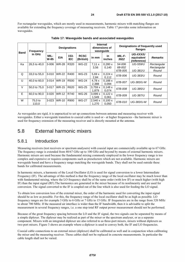
For rectangular waveguides, which are mostly used in measurements, harmonic mixers with matching flanges are available for extending the frequency coverage of measuring receivers. Table 17 provides some information on waveguides.
Table 17: Waveguide bands and associated waveguides
Band Frequency in GHz
Designations Internal
dimensions of waveguide
Designations of frequently used flanges
MIL-W-85 EIA 153-
IEC RCSC
(British) in mm in inches
MIL-F-3922
UG-XXX/U equivalent (reference)
Remarks
Ka 26,5 to 40,0 3-006 WR-28 R320 WG-22 7,11 x 3,56
0,280 x 0,140
54-006 68-002
67B-005
UG-559/U -
UG-381/U
Rectangular Rectangular
Round Q 33,0 to 55,0 3-010 WR-22 R400 WG-23 5,69 x
2,84 0,224 x 0,112
67B-006 UG-383/U Round
U 40,0 to 60,0 3-014 WR-19 R500 WG-24 4,78 x 2,388
0,188 x 0,094
67B-007 UG-383/U-M Round
V 50,0 to 75,0 3-017 WR-15 R620 WG-25 3,759 x 1,879
0,148 x 0,074
67B-008 UG-385/U Round
E 60,0 to 90,0 3-020 WR-12 R740 WG-26 3,099 x 1,549
0,122 x 0,061
67B-009 UG-387/U Round
W 75,0 to 110,0
3-023 WR-10 R900 WG-27 2,540 x 1,270
0,100 x 0,050
67B-010 UG-383/U-M Round
As waveguides are rigid, it is unpractical to set up connections between antenna and measuring receiver with waveguides. Either a waveguide transition to coaxial cable is used or - at higher frequencies - the harmonic mixer is used for frequency extension of the measuring receiver and is directly mounted at the antenna.
5.8 External harmonic mixers
5.8.1 Introduction
Measuring receivers (test receivers or spectrum analysers) with coaxial input are commercially available up to 67 GHz. The frequency range is extended from 40/67 GHz up to 100 GHz and beyond by means of external harmonic mixers. Harmonic mixers are used because the fundamental mixing commonly employed in the lower frequency range is too complex and expensive or requires components such as preselectors which are not available. Harmonic mixers are waveguide based and have a frequency range matching the waveguide bands. They shall not be used outside these bands for calibrated measurements.
In harmonic mixers, a harmonic of the Local Oscillator (LO) is used for signal conversion to a lower Intermediate Frequency (IF). The advantage of this method is that the frequency range of the local oscillator may be much lower than with fundamental mixing, where the LO frequency shall be of the same order (with low IF) or much higher (with high IF) than the input signal (RF).The harmonics are generated in the mixer because of its nonlinearity and are used for conversion. The signal converted to the IF is coupled out of the line which is also used for feeding the LO signal.
To obtain low conversion loss of the external mixer, the order of the harmonic used for converting the input signal should be as low as possible. For this, the frequency range of the local oscillator shall be as high as possible. LO frequency ranges are for example 3 GHz to 6 GHz or 7 GHz to 15 GHz. IF frequencies are in the range from 320 MHz to about 700 MHz. If the measured air interface is wider than the IF bandwidth, then it is advisable to split the measurement in several frequency ranges, i.e. a one step total RF output power measurement should not be performed.
Because of the great frequency spacing between the LO and the IF signal, the two signals can be separated by means of a simple diplexer. The diplexer may be realized as part of the mixer or the spectrum analyser, or as a separate component. Mixers with an integrated diplexer are also referred to as three-port mixers, mixers without diplexers as two-port mixers. Figure 3 shows an example where a diplexer is used to convey both, the IF and LO frequencies.
Coaxial cable connections to an external mixer (diplexer) shall be calibrated as well and in conjunction when calibrating the mixer and the measuring receiver. Those cables shall not be replaced in concrete measurements. In particular the cable length shall not be varied.

ETSI
Draft ETSI EN 305 550 V2.1.0 (2017-10) 25
It shall be regarded that the mixer inputs are sufficiently insulated towards the antenna port with regard to the injected signal (mixed signal) so that the mixed signal, multiplied by the LO, is sufficiently absorbed.
Figure 3: Set-up of measurement receiver, diplexer and mixer
5.8.2 Signal identification
A setup with Harmonic mixers without pre-selection displays always a pair of signals with a spacing of 2 × fIF, as there is no image suppression. For a modulated signal with a bandwidth of > 2 × fIF both, wanted and image response overlap and cannot be separated any more.
Depending on the width of the analysed frequency bands additional responses created from other harmonics may be displayed. In these cases it has to be determined with good engineering practice, which of the displayed responses are false responses. Signal identification techniques implemented in spectrum analysers are based on the fact that only responses corresponding to the selected number of harmonic show a frequency spacing of 2 × fIF.
This can be used for automated signal identification: Apart from the actual measurement sweep, in which the lower sideband is defined as "wanted", a reference sweep is performed. For the reference sweep, the frequency of the LO signal is tuned such that the user-selected harmonic of the LO signal (order m') is shifted downwards by 2 × fIF relative to the measurement sweep.
Parameters which influence the signal identification routines are:
• Number of harmonic: the higher the harmonic number the more false responses will be created. A high LO frequency range which results in a lower harmonic number for a given frequency range is desirable.
• IF Frequency: the higher the IF frequency of the spectrum analyser, the greater the spacing at which image frequency response is displayed on the frequency axis. For a single modulated or unmodulated input signal displayed on the frequency axis, an image-free range of 2 × fIF is obtained around this signal in which no signal identification is necessary.
5.8.3 Measurement hints
To obtain accurate and reproducible results, the following points should be observed:
• A low-loss cable with a substantially flat frequency response should be used for feeding the LO signal to the mixer. The conversion loss of the mixer is normally specified for a defined LO level. It is therefore important to maintain this level at the LO port of the mixer in order to achieve the desired accuracy. This is especially essential if the antenna/mixer combination is located away from the measuring receiver.
• In level correction on the spectrum analyser, the insertion loss of the cable used for tapping the IF signal is to be taken into account.
• If an external diplexer is used for connecting a two-port mixer, the insertion loss of the IF path of the diplexer is to be taken into account in level correction on the spectrum analyser.

ETSI
Draft ETSI EN 305 550 V2.1.0 (2017-10) 26
Additional information on radiated measurements up to 100 GHz is available in ETSI TS 103 052 [3].
5.9 Interpretation of the measurement results
5.9.0 General
The interpretation of the results for the measurements described in the present document shall be as follows:
1) the measured value related to the corresponding limit shall be used to decide whether an equipment meets the requirements of the present document;
2) the measurement uncertainty value for the measurement of each parameter shall be recorded;
3) the recorded value of the measurement uncertainty shall be wherever possible, for each measurement, equal to or less than the figures in table 18.
For the test methods, according to the present document, the measurement uncertainty figures shall be calculated in accordance with the guidance provided in ETSI TR 100 028 [i.8] and shall correspond to an expansion factor (coverage factor) k = 1,96 or k = 2 (which provide confidence levels of respectively 95 % and 95,45 % in the case where the distributions characterizing the actual measurement uncertainties are normal (Gaussian)).
Table 18 is based on such expansion factors.
Table 18: Maximum measurement uncertainties
Parameter Maximum expanded measurement Uncertainty
Radio frequency ±1 × 10⁻⁷ Radiated RF power (up to 40 GHz) ±6 dB Radiated RF power (above 40 GHz up to 66 GHz) ±8 dB Radiated RF power (above 66 GHz up to 100 GHz) ±10 dB (see note 1) Radiated RF power (above 100 GHz) See note 2 Temperature ±1 °C Humidity ±5 % DC and low frequency voltages ±3 % NOTE 1: Achieved sensitivity and measurement uncertainty are a direct result of the chosen test
suites. The values mentioned together with the concerns should therefore be considered illustrational rather than absolute for measurements above 66 GHz, given the absence of some relevant information. For radiated emissions above 66 GHz the given measurement uncertainties are based on the assumption of the deployment of a cable based measurement set-up. In the cases of other measurement set-up (e.g. wave guides) it may not be possible to reduce measurement uncertainty to the levels specified in this table.
NOTE 2: For measurements above 100 GHz, the expanded measurement uncertainty shall also be recorded in the test report and a detailed calculation be added. A future revision of the present document may include a value for frequencies for expanded measurement uncertainty that is still under development.
The measurement uncertainty of measurements in the range above 40 GHz (millimetre domain) will be clearly above the initially assumed 6 dB for radiated measurements below 40 GHz. A value of 8 dB seems to be more adequate. Precise values of measurement uncertainty require calibration, and there are limitations as mentioned on above.
This maximum uncertainty value above 40 GHz is also dependent upon the maximum dimensions of the antenna of the equipment under test and is also dependent upon gain specifications of antennae.
5.9.1 For measurement above 110 GHz
"Standard" measurement equipment is only available up to a frequency range of around 110 GHz with a limited sensitivity related to measurement BWs and detectors. For higher frequencies above 110 GHz the sensitivity will further decrease.

ETSI
Draft ETSI EN 305 550 V2.1.0 (2017-10) 27
The commercially available calibration capability is currently limited to around 110 GHz. As a consequence measurement results above 110 GHz of different laboratories are not fully comparable since the equipment will not be calibrated for the needed operational range.
5.9.2 Conversion loss data and measurement uncertainty
Calibrated conversion loss data for harmonic mixers are given for a dedicated number of harmonic, IF frequency and LO power. They cannot be used for a different number of harmonic. It is equally essential that the LO level at the harmonic mixer matches the LO level for which the conversion loss data have been derived.
The above conditions adhered to a measurement uncertainty including the measuring receiver of < ±3 dB to 5 dB at the frequency of the calibration points can be expected, depending on the waveguide band.
EXAMPLE: 75 GHz to 110 GHz 3-port harmonic mixer: < 4,5 dB (K = 2,5 °C to 45 °C).
Harmonic mixers frequently have a low return loss (typically 6 dB to 7 dB), which increases the measurement uncertainty. It is therefore expedient to insert an attenuator or isolator between the mixer and the antenna in order to improve measurement uncertainty. However, the insertion loss caused by such a component will reduce the sensitivity of the spectrum analyser and mixer setup. This insertion loss has also to be taken into account for level measurements.
Mixers with integrated isolator are preferable, as they are already calibrated with the isolator included.
As frequency ranges increase it may be difficult to conclude a maximum allowable value for the expanded measurement uncertainty due to lack of knowledge of the new methods of test and determining the uncertainty components:
• The commercially available calibration capability is limited to around 66 GHz. Thus no such possibility is freely available on the market above that limit. As a consequence measurement results above 66 GHz of different labs are not fully comparable since the equipment will not be calibrated for the needed operational range and also for radiated unwanted emission measurements above the operational range.
• The expanded measurement uncertainty of measurements in the range between 66 GHz and 100 GHz will be clearly above the values valid for below 66 GHz. Precise values of expanded measurement uncertainty require calibration and there are limitations as mentioned above.
• In general it has to be mentioned that these values become the higher the frequency will become the more a guideline.
• Starting from around 66 GHz the limits of coaxial systems are reached and the frontend has to switch to wave guide based technologies adding an additional attenuation and also decreasing the sensitivity. Commercially available analysers can only measure up to around 67 GHz, thus making the use of external mixers unavoidable.
Guidance is provided in ETSI TR 102 215 [i.6] and its revision that will present an evaluation of maximum acceptable measurement uncertainty for Radio Frequency (RF) electromagnetic field (emf) measurements for the frequency range from 30 MHz to 100 GHz for inclusion within ETSI documents on radio products used for compliance testing.
5.9.3 Measurement uncertainty is equal to or less than maximum acceptable uncertainty
If measurement uncertainty is equal to or less than maximum acceptable uncertainty the interpretation shall be as given in ETSI EN 303 396 [4], clause 4.6.2.
5.9.4 Measurement uncertainty is greater than maximum acceptable uncertainty
If measurement uncertainty is greater than maximum acceptable uncertainty the interpretation shall be as given in ETSI EN 303 396 [4], clause 4.6.3.

ETSI
Draft ETSI EN 305 550 V2.1.0 (2017-10) 28
6 Conformance test suits
6.1 Introduction In this clause the general setup of a test bed for the test of equipment will be described.
A detailed introduction shall be considered as in ETSI EN 303 396 [4], clause 5.1.
6.2 Initial Measurement steps Initial measurement steps shall be done as described in ETSI EN 303 396 [4], clause 5.2.
6.3 Radiated measurements
6.3.1 General
The provisions of ETSI EN 303 396 [4], clause 5.3.1 and the specific requirements for the very high frequencies within annex B shall apply.
6.3.2 Test sites and general arrangements for measurements involving the use of radiated fields
The provisions of ETSI EN 303 396 [4], clause A.2 shall apply.
6.3.3 Guidance on the use of a radiation test site
6.3.3.1 General
The provisions of ETSI EN 303 396 [4], clause 5.3.2 shall apply.
6.3.3.2 Minimum requirements for test sites for measurements above 18 GHz
Generally the test site shall be adequate to allow for testing in the far field of the EUT. The test site should therefore consist of an electromagnetic anechoic room where either at least the ground surface is covered with radio absorbing material or up to six surrounding surfaces are covered with radio absorbing material. The absorbing material shall have a minimum attenuation of 30 dB. It shall be verified that reflections are sufficiently reduced. The test site shall have the following dimensions:
• Width of 2 meters.
• Length of 3 meters.
• Height of 2 meters (only applicable for a room with more than one reflecting surface).
Highly directional receiving antennas help in reducing reflections. The use of standard gain horn antennas is recommended. It shall be noted that if the antenna aperture is smaller than the EUT, sufficient measurements in both azimuth and elevation shall be conducted in order to ensure that the maximum radiation is determined.
The measuring distance shall be selected in such way that antenna coupling effects are avoided. A distance of at least 0,5 m is therefore recommended. The EUT may be positioned at any height that minimizes reflections from the floor.
Due to high loss of coaxial cables at higher frequencies, the connection from the receiving antenna to the measuring receiver should not exceed 1 m, thus making it necessary to place the measuring receiver very close. This is especially the case when using external harmonic mixers with very short connections to the measuring receiver. Therefore the measuring receiver should somehow be covered with radio absorbing material in direction to the measuring field in order to reduce reflections. Figure 4 shows an example of a test site above 18 GHz with one reflecting surface.

ETSI
Draft ETSI EN 305 550 V2.1.0 (2017-10) 29
Receiving antenna or harmonic mixer with antenna
Measuring receiver
Radio absorbing material
EUT
Non conductive material
Coaxial cable
Site attenuation
Figure 4: Example of a test site above 18 GHz with one reflecting surface
The site attenuation of the test site can be determined. Should the test site in its characteristics be nearly ideal, it may be possible to use the theoretical Free Space Loss (FSL) as site attenuation as shown in the examples in the tables 19 to 21.
Table 19: Example of Free Space Loss at 1 m distance
Measuring distance/m f/GHz λ/ 1 m [FSL]/dB
1
24,2 0,012397 60,12 48,4 0,006198 66,14 72,6 0,004132 69,66 96,8 0,003099 72,16
Table 20: Example of Free Space Loss at 0,5 m distance
Measuring distance/m f/GHz λ/ 1 m [FSL]/dB
0,5
24,2 0,012397 54,1 48,4 0,006198 60,12 72,6 0,004132 63,64 96,8 0,003099 66,14
Table 21: Example of Free Space Loss at 0,25 m distance
Measuring distance/m f/GHz λ/ 1 m [FSL]/dB
0,25 72,6 0,004132 57,62 96,8 0,003099 60,12
Whereas:
λ = c/f
[FSL] = 10 log (4πr/λ)2
6.3.3.3 Range length.
The provisions of ETSI EN 303 396 [4], clause 5.3.2.3 shall apply.

ETSI
Draft ETSI EN 305 550 V2.1.0 (2017-10) 30
6.3.4 Standard test and calibration methods
The provisions of ETSI EN 303 396 [4], clause 5.3.3 shall apply.
6.4 Test fixture
6.4.1 Requirements
The test fixture for radio equipment operating in the relevant frequency range shall enable the EUT to be physically supported, together with a wave-guide horn antenna Rx, which is used to measure the transmitted energy, in a fixed physical relationship to the EUT or calibration antenna Tx (see figure 5). The test fixture shall be designed for use in an anechoic environment and allow certain measurements to be performed in the far field, i.e. at a distance greater than 2d2/ , where d is the largest dimension of the antenna aperture of the EUT.
The test fixture shall incorporate at least one RF connector, a device for electromagnetic coupling to the EUT and a means for repeatable positioning of the EUT. Its compactness shall enable the whole assembly to be accommodated within a test chamber, usually a climatic facility. The circuitry associated with the RF coupling device shall not contain active or non-linear components.
Only after it has been verified that the test fixture does not affect performance of the EUT, the EUT can be confidently tested.
At set-up, the EUT shall be aligned in the test fixture so that the maximum power is detected at the coupled output. Orientation of the horn antenna will take into account the polarization of the EUT.
In addition, the test fixture shall provide a connection to an external power supply.
The test fixture shall be provided by the manufacturer together with a full description, which shall meet the approval of the selected accredited test laboratory.
The performance characteristics of the test fixture shall be measured and shall be approved by the accredited test laboratory. It shall conform to the following basic parameters:
• the gain of the waveguide horn shall not exceed 20 dB;
• the minimum distance between the transmitting and receiving antenna shall guarantee mutual far field conditions (distance greater than 2d2/ , where d is the largest dimension of the antenna aperture of the EUT);
NOTE 1: Information on uncertainty contributions, and verification procedures are detailed in clauses 5 and 6, respectively, of ETSI TR 102 273 [i.7].
NOTE 2: The far field conditions of the test setup have to be carefully verified in the frequency band covered by the present document. It is highly recommended that the Voltage Standing Wave Ratio (VSWR) at the waveguide flange at which measurements are made is not greater than 1,5.
• the performance of the test fixture when mounted in the anechoic chamber or in a temperature chamber, shall be unaffected by the proximity of surrounding objects or people inside the chamber. The performance shall be reproducible if the EUT is removed and then replaced;
• the performance of the test fixture shall remain within the defined limits of the calibration report, when the test conditions are varied over the limits described in clauses 5.2.
The characteristics and calibration of the test fixture shall be included in a calibration report.
6.4.2 Calibration
The calibration of the test fixture establishes the relationship between the detected output from the test fixture, and the transmitted power (as sampled at the position of the antenna) from the EUT in the test fixture. This can be achieved by using a calibrated horn with a gain of equal to or less than 20 dB, fed from an external signal source, in place of the EUT to determine the variations in detected power with temperature and over frequency.
λ
λ

ETSI
Draft ETSI EN 305 550 V2.1.0 (2017-10) 31
The calibration of the test fixture shall be carried out by either the manufacturer of the EUT or the accredited test laboratory. The results shall be approved by the accredited test laboratory.
The calibration should be carried out over the operating frequency band, at least three frequencies, for the declared polarization of the EUT.
WaveguideHorn
Waveguide InterfaceFlange
EquipmentUnder Test
50 c
m to
60
cm
50 cm to 60 cm
15 cm Pyramidabsorber
Figure 5: Example of the test fixture
More detailed information about use, validation and performance limitations of test fixtures up to 100 GHz shall be taken from ETSI TS 103 052 [3].
6.5 Conformance methods of measurement for transmitter
6.5.1 General
First the complete signal device shall be measured for:
• the maximum mean power (e.i.r.p.);
• the maximum mean power spectral density (e.i.r.p.);
• the operating bandwidth(s);
• the receiver spurious emissions.
The following methods of measurement shall apply to the testing of stand-alone units and to the equipment configurations identified in clause 5.2.
6.5.2 Operating frequency range(s) (OFR)
Operating frequency range measurements shall be performed as given in ETSI EN 303 396 [4], clause 6.3.2.
The results for fL, fH, , OBW, and fC shall be reported in the test report.
6.5.3 Mean Power
Mean Power measurements shall be performed as given in ETSI EN 303 396 [4], clause 6.3.4.
The results shall be reported in the test report.
6.5.4 Mean power spectral density measurements
Mean Power measurements shall be performed as given in ETSI EN 303 396 [4], clause 6.3.5.

ETSI
Draft ETSI EN 305 550 V2.1.0 (2017-10) 32
The results shall be reported in the test report.
6.5.5 Transmitter unwanted emissions
Mean Power measurements shall be performed as given in ETSI EN 303 396 [4], clause 6.3.10.
The results shall be reported in the test report.
6.6 Conformance methods of measurement for receiver
6.6.1 Receiver spurious emissions
Receiver spurious emissions measurements shall be as given in ETSI EN 303 396 [4], clause 6.3.11.
The measurement method, level and type (narrowband or wideband) of spurious emissions shall be recorded in the test report.
6.6.2 Receiver interference signal handling
Interference signal handling measurements shall be as given in ETSI TS 103 361 [5], clause 9.
For the interferer signals the information in clause 4.4.3 shall apply.
The interferer test frequency range, interferers and interferer power levels, test scenario, performance criterion and level of performance shall be recorded in the test report.

ETSI
Draft ETSI EN 305 550 V2.1.0 (2017-10) 33
Annex A (informative): Relationship between the present document and the essential requirements of Directive 2014/53/EU The present document has been prepared under the Commission's standardisation request C(2015) 5376 final [i.10] to provide one voluntary means of conforming to the essential requirements of Directive 2014/53/EU on the harmonisation of the laws of the Member States relating to the making available on the market of radio equipment and repealing Directive 1999/5/EC [i.9].
Once the present document is cited in the Official Journal of the European Union under that Directive, compliance with the normative clauses of the present document given in table A.1 confers, within the limits of the scope of the present document, a presumption of conformity with the corresponding essential requirements of that Directive, and associated EFTA regulations.
Table A.1: Relationship between the present document and the essential requirements of Directive 2014/53/EU
Harmonised Standard ETSI EN 305 550 Requirement Requirement Conditionality
No Description Essential
requirements of Directive
Clause(s) of the present
document U/C Condition
1 Permitted range of operating frequencies
3.2 4.3.1 U
2 Operating frequency range(s) (OFR) 3.2 4.3.2 U 3 Mean Power 3.2 4.3.3 U 4 Mean Power spectral density 3.2 4.3.4 C Only for the frequency
ranges with a given limit 5 Unwanted emissions in the
out-of-band domain 3.2 4.3.5 U
6 Unwanted emissions in the spurious domain
3.2 4.3.6 U
7 Receiver spurious emissions 3.2 4.4.2 U 8 Receiver interference signal handling 3.2 4.4.3 U
Key to columns:
Requirement:
No A unique identifier for one row of the table which may be used to identify a requirement.
Description A textual reference to the requirement.
Essential requirements of Directive
Identification of article(s) defining the requirement in the Directive.
Clause(s) of the present document
Identification of clause(s) defining the requirement in the present document unless another document is referenced explicitly.
Requirement Conditionality:
U/C Indicates whether the requirement is unconditionally applicable (U) or is conditional upon the manufacturer's claimed functionality of the equipment (C).
Condition Explains the conditions when the requirement is or is not applicable for a requirement which is classified "conditional".

ETSI
Draft ETSI EN 305 550 V2.1.0 (2017-10) 34
Annex B (informative): Measurement antenna, preamplifier, and cable specifications The radiated measurements set-up in annex B of ETSI EN 303 396 [4] specifies the use of a horn antenna and a wide-band high gain preamplifier above 1 GHz in order to measure the very low radiated power density level from UWB equipment.
Table B.1 gives examples of recommended data and features for the horn antenna and preamplifier to be used for the test set-up.
Table B.1: Recommended Hardware
Device Parameter Value
Preamplifier LNA
Bandwidth < 1 GHz to > 15 GHz NF < 2,5 dB Gain > 30 dB Gain flatness across band ±1,5 dB VSWR in/out across band < 2:1 Nominal impedance 50 Ω
RX Horn Antenna
3 dB bandwidth < 1 GHz to > 15 GHz VSWR across band < 1,5:1 Gain (10 GHz) > 16 dBi Gain (8 GHz) > 14 dBi Gain (6 GHz) > 12,5 dBi Gain (2-5 GHz) > 10 dBi Nominal impedance 50 Ω
Cable
Nominal impedance 50 Ω VSWR < 1,2:1 Shielding > 60 dB Losses Take losses into account for total
gain calculations NOTE: The noise floor of the combined equipment should be at least 6 dB below the specified limits, but
10 dB would be optimal.

ETSI
Draft ETSI EN 305 550 V2.1.0 (2017-10) 35
Annex C (informative): Atmospheric absorptions and material dependent attenuations
C.0 General In the frequency range between 40 GHz and 246 GHz the specific absorptions and material attenuations are an important factor for the compatibility of the different services potentially sharing the same operational band. In this annex an overview over the relevant parameters will be given for different materials and the atmospheric absorption.
More detail can be found in ITU-R Recommendation ITU-R P.676-5 [i.4].
C.1 Atmospheric absorptions With higher frequencies the effect of the atmospheric absorption gets more and more important in the investigation of the coexistence behaviour of short range wireless systems. In figure C.1 the specific absorption in the band between 1 GHz and 350 GHz is depicted. The diagram shows the absorption behaviour of dry air, of H2O and the combination of both. It can be seen that under normal conditions the absorption due to H2O is the most significant effect. Only in two spectral regions around 60 GHz and 120 GHz the dry air already shows a very significant absorption behaviour. That means these absorptions are independent of the amount of H2O in the air. Especially the absorption peak around 60 GHz will be used to increase the isolation behaviour between different wireless systems. The absorption peak around 60 GHz originates from several oxygen absorption lines. A more detailed description of the behaviour around 60 GHz is depicted in figure C.2 for different altitudes between 0 km (see level) and 20 km. Especially the 20 km diagram shows nicely the different absorption lines. The absorption peak around 60 GHz reaches 16 dB/km.

ETSI
Draft ETSI EN 305 550 V2.1.0 (2017-10) 36
Figure C.1: Specific attenuation due to atmospheric gases in the band 1 GHz to 350 GHz in dB/km

ETSI
Draft ETSI EN 305 550 V2.1.0 (2017-10) 37
Figure C.2: Specific Atmospheric attenuation in the band 50 GHz to 70 GHz for different altitudes (0 km, 5 km, 10 km, 15 km and 20 km) [i.5]
C.2 Material dependent attenuations The material dependent attenuation does also increase with the operational frequency. Typical attenuations for different materials are depicted in figure C.3 for the frequency range between 3 GHz and 200 GHz. These effects are important when coexistence scenarios are investigated between indoor and outdoor systems.
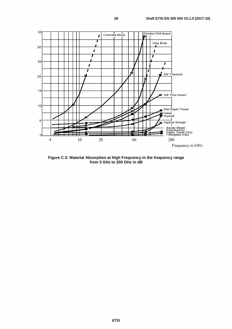
ETSI
Draft ETSI EN 305 550 V2.1.0 (2017-10) 38
Figure C.3: Material Absorption at High Frequency in the frequency range from 3 GHz to 200 GHz in dB

ETSI
Draft ETSI EN 305 550 V2.1.0 (2017-10) 39
Annex D (informative): Bibliography
• ETSI EN 301 489-3 (V1.2.1): "Electromagnetic compatibility and Radio spectrum Matters (ERM); ElectroMagnetic Compatibility (EMC) standard for radio equipment and services; Part 3: Specific conditions for Short-Range Devices (SRD) operating on frequencies between 9 kHz and 40 GHz".
• Recommendation ITU-R SM.1755: "Characteristics of ultra-wideband technology".
• Directive 1999/5/EC of the European Parliament and of the Council of 9 March 1999 on radio equipment and telecommunications terminal equipment and the mutual recognition of their conformity (R&TTE Directive).
• ETSI EN 300 440-2 (V1.3.1): "Electromagnetic compatibility and Radio spectrum Matters (ERM); Short range devices; Radio equipment to be used in the 1 GHz to 40 GHz frequency range; Part 2: Harmonized EN covering essential requirements of article 3.2 of the R&TTE Directive".
• European Commission Decision 2008/432/EC of 23 May 2008 (amending Decision 2006/771/EC) on harmonization of the radio spectrum for use by short-range devices.
• European Commission Decision 2009/381/EC of 13 May 2009 (amending Decision 2006/771/EC) on harmonization of the radio spectrum for use by short-range devices.
• European Commission Decision 2011/829/EC of 8 December 2011 (amending Decision 2006/771/EC) on harmonization of the radio spectrum for use by short-range devices.
• ECC Report 176: "The impact of non-specific SRDs on radio service in the band 57-66 GHz" (March 2012).
• ECC Report 190: "Compatibility between Short-Range Devices (SRD) and EESS (passive) in the 122 to 122.25 GHz band" (May 2013).
• CEPT report 44, In response to the EC Permanent Mandate on the "Annual update of the technical annex of the Commission Decision on the technical harmonisation of radio spectrum for use by short range devices", Report approved on 8 March 2013 by the ECC.
• Recommendation ITU-R SM.329-12 (09/2012): "Unwanted emissions in the spurious domain, SM Series, Spectrum management".

ETSI
Draft ETSI EN 305 550 V2.1.0 (2017-10) 40
Annex E (informative): Change history
Version Information about changes 1.2.1 (part 1) 1.2.1 (part 2) Last publication as two-part HS
2.1.1
• Revision for compliance with Directive 2014/53/EU • The EN was merged into a single EN • Add new requirement "interferer signal handling" • Changes in the TX emissions (regulation) within the 122 GHz - 123 GHz range was
reflected

ETSI
Draft ETSI EN 305 550 V2.1.0 (2017-10) 41
History
Document history
V1.1.1 July 2011 Publication as ETSI EN 305 550 part 1 and part 2
V1.2.1 October 2014 Publication as ETSI EN 305 550 part 1 and part 2
V2.1.0 October 2017 EN Approval Procedure AP 20180114: 2017-10-16 to 2018-01-15