draft: kinematic analysis of a skid-steer mobile robot
TRANSCRIPT

1
Proceedings of the ASME 2016 International Design Engineering Technical Conferences and Computers and Information in Engineering Conference
IDETC 2016 August 21-24, 2016, Charlotte, North Carolina
IDETC2016-60303
DRAFT: KINEMATIC ANALYSIS OF A SKID-STEER MOBILE ROBOT OPERATING ON NON-PLANAR SURFACES
Joshua Qualls
Tennessee Technological University Cookeville, Tn. USA
Stephen Canfield Tennessee Technological University
Cookeville, Tn. USA
Alexander Shibakov Tennessee Technological University
Cookeville, Tn. USA
ABSTRACT:
Mobile robotic systems are advancing manufacturing operations
that generally exhibit less automation. Fields commonly
experiencing a lesser degree of automation include shipbuilding,
pipe inspection, and construction applications on non-planar
surfaces. The mobile robotic systems operating in such
environments are typically subjected to motion along non-planar
surfaces and often assume climbing configurations when
completing the desired tasks. These tasks are usually considered
planar in nature, however, in practice the surface on which the
tasks are completed is generally non-planar. The surfaces are
commonly modeled as geometric shapes such as spheres or
cylinders allowing for accurate surface representations. A
common non-planar task is the welding of ship hulls. The
process consists of welding segments together and is normally
completed by a skilled laborer due to the curvature of the surface.
Through the advancement of kinematic modeling of mobile
robotic platforms there exists the ability to develop future robotic
platforms with the potential to perform operations, in a task
efficient manner, on non-planar surfaces. While the majority of
kinematic models presented for mobile robots assume operation
on planar surfaces, there have been a number of studies that
consider the kinematic behavior on non-planar surfaces. This
past work generally takes one of two approaches, either
developing assumed modifications to the existing kinematic
constraints as algebraic equations, or making use of a set of
differential equations describing the instantaneous motion of the
contact point between non-planar surfaces. The second approach
is more general and has been shown to be applicable to both
general and specific terrains. However, the previous work has
focused solely on differential-steer platforms with a passive
castor. Conversely, Skid-Steer mobile robots provide simple,
robust platforms that have several features making them well
suited to manufacturing tasks. This paper will present a
kinematic model for an SSMR operating on a non-planar,
nominally cylindrical surface. This method is readily generalized
to other surface geometries. The method is based on a kinematic
model consisting of a set of differential-algebraic equations with
the differential equations derived from Montana’s contact
equations and the algebraic equations arising from an
instantaneous model of the SSMR as a hybrid mechanism
consisting four, five-dof serial chains. The method is
demonstrated over several applications and validated through
comparison with a prototype system operating on a cylindrical
tank. A discussion of the resulting approach and how this could
be used in as a tool to guide the modeling and fabrication of
future mobile manufacturing robot platforms is included.
INTRODUCTION
As mobile robots gain interest in various industries their
incorporation into manufacturing applications is increasing in
areas such as mobile inspection, welding, and painting, [1].
Research focusing on applications within these areas has
typically been driven by the need to control the desired path in
order to complete the required task at hand. The advanced
control strategies needed to accommodate such motion has
greatly improved in part due to continued research in the area of
mobile kinematics and dynamics. This research has allowed for
the development of robust models to accurately predict the
behavior of the robotic platform as it navigates along a desired
path. Typically, robotic topologies incorporate wheels enabling
mobility, therefore rolling motion has been widely studied [2-3].
The primary constraints for this rolling motion is provided by the
contact point between the wheels and the surface.
Tracked mobile robots are also widely studied in the literature
[4-7] and make use of an approach similar in nature to the rolling
motion of wheels, [4]. The models for wheeled vehicles rely on
the pure roll and no slip assumptions, which is valid when
dynamic effects are minimal, however, in the case of tracked
vehicles it is accepted that slipping occurs between the tracks and
terrain, therefore the pure roll and no slip assumptions are not
valid, [8-10]. The consideration of slip has been focused on by
many works, [11-12], and is often incorporated into the
kinematic models for the differential, skid, and omni-directional
robot platforms, [12-14]. While these techniques are quite
useful, their main limitation is the surface of operation. Typically
mobile robot operation is assumed to occur on a planar surface

2
when in reality the desired tasks are usually carried out on non-
planar surfaces. Consider a robot performing a seam weld on a
storage tank or a ship hull. The typical welding path is
constructed by segments of linear spines called gaits and are
often found on surfaces of varying curvature; in order for the
robot to complete the desired task along the path adequate
information about the path and robot location must be provide.
The motion of the robot is dependent on the surface through the
knowledge that the kinematics of vehicles are dependent on the
terrain, [14-15], thus in order to provide accurate information on
the robots position and orientation effects of the non-planar
surface must be accounted for in the kinematic model. This
accommodation of non-planar surface conditions has been
studied by previous researchers, [16-18], with a kinematic model
of contact provided by Montana, [19]. This model incorporates a
set of contact equations, constructed from a set of five first order
ordinary differential equations, and used to describe the motion
of the contact point between two surfaces. These contact
equations have been used in areas ranging from mobile robot
kinematics to the kinematics of grasping objects, [16-18, 20],
and hold valid for a variety of surfaces that can be characterized.
This paper follows the work presented in [18, 21, 22-23].
However, the previous works, [16, 21] employed a strategy used
to investigate wheeled robot behavior over an arbitrary terrain
without slip. It is apparent however that slip is necessary in order
to achieve certain degrees of motion, as is the case with skid steer
platforms, thus requiring a more robust model with the capability
to estimate the path of the mobile robot when subjected to
slipping conditions. The proposed formulation satisfies the same
set of constraints as in [16,21] although instead assuming the
translational motion of the contact points between the wheels and
the surface are zero, the current model allows for the
incorporation of slip. The amount of slip being experienced is
then determined by the location of the instant centers as the
mobile robot navigates along the climbing surface. The primary
context of this work is for mobile manufacturing in which
manufacturing tasks are performed with mobile manipulators.
Consider a mobile manufacturing robot, such as that
described in [1] and shown for example in Fig. 1. In this
example, the robot is operating on a cylindrical tank performing
inspection processes for pitting or cracking. The robot is driven,
either through remote operation or with some closed-loop
control, to follow a specific path defined by the parameters of the
specific inspection task. This maneuver requires the robot to
collect adequate data about the surface condition and relay that
information to observers. This task represents a large grouping
of manufacturing tasks that are ideally suited to mechanization
through mobile robots. The primary objective of this paper is to
develop a kinematic model of the robot system when operating
on non-planar navigation that is suitable for skid-steer mobile
robots (SSMR). This model will build directly on the approach
developed in [21] for differential steer mobile robot systems
operating on non-planar surfaces. The primary climbing surface
assumed in this paper is modeled as a spherical surface, however,
the approach can be applied to a variety of surfaces through
means of defining curvature, metric and torsion of the varying
surfaces.
Figure 1: Mobile Robot Performing Surface Inspection
APPROACH
A model is developed for the SSMR consisting of two tracks (left
and right) and operating on a non-planar surface. An equivalent
model of the SSMR is constructed as a multi-body system in
which the contact portion of each track and the chassis represent
bodies on the robot and are connected through a set of prismatic
joints lying longitudinally along the robot with its axis aligned
with the longitudinal direction of the robot and an additional
revolute joint between the right track and chassis (Fig. 3). The
contact patch of each tract couples to the surface with a higher
pair contact. The climbing surface is modeled as a sphere with
the inertial frame, {I}, located at the center.
Frame Assignments:
The motion generated by the robot along the climbing surface is
defined using a series of frames. The frame notation used here
follows the notation provided in [22].These frames represent the
robot local frame {r}, the contact frames for the spherical
climbing surface, {Si}, and each robot track, {Ti}, with i= L, R,
C. Figure 3 shows the inertial frame through the point of contact
while Figure 2 represents the robot kinematic model. The
contact point for each track is then determined through a set of
coincident frames. Two of these frames are defined according the
geometry of the contact surfaces following the method provided
in [17]; {Si} and {Ti}. The third frame, {0i} serves as the first in
a chain describing the robot kinematics. Frames {Si} and {Ti}

3
are constructed to form an outward normal Gaussian map for the
surface. Frame {Si} describes the climbing surface at the point
of contact of track i and is located relative to {I} through the
spherical coordinates 𝜃 and 𝜙 as,
𝑇𝑆𝑖𝐼 = [
𝑠𝜃𝑖𝑐𝜙𝑖 𝑠𝜃𝑖𝑠𝜙𝑖 𝑐𝜃𝑖 𝑅𝑐𝜃𝑖𝑠𝜙𝑖
𝑐𝜃𝑖𝑐𝜙𝑖 𝑐𝜃𝑖𝑠𝜙𝑖 −𝑠𝜃𝑖 𝑅𝑠𝜃𝑖𝑠𝜙𝑖
−𝑠𝜙𝑖 𝑐𝜙𝑖 0 𝑅𝑐𝜃𝑖
0 0 0 1
] (1)
Where 𝜃𝑖 and, 𝜙i represent rotations about the global Z and X
axes and R is the radius of the sphere. Frame {Ti} describes the
contact point of the track surface and is located relative to {Si}
by a rotation of ψ about the zS axis with zt = -zs. Finally, frame
{0i} is defined as a fixed rotation relative to {Ti} to facilitate
D&H frame assignment;
𝑅𝑂𝑖𝑇𝑖 = [
0 0 1−1 0 00 −1 0
] (2)
Mobile Robotic Kinematics:
An instantaneous model of the robot is shown in Figure 2 as a
schematic in a two-dimensional view with the length and width
of the robot is denoted as l and 2b respectively. Figure 2 also
represents the system in 3D as a parallel mechanism constructed
from three serial chains, similar to that seen in, [21]. Note that
an additional chain is added to the model to add a single point of
stability to the model that assumes only one contact point for
each track. In practice, deflection in the track will make contact
at more than one point. The contact point for each track is
assumed a higher-pair point contact that can experience a
combination of rotation and slip relative to the surface. The slip
for each wheel is calculated using the kinematic characterization
procedure demonstrated in [1] for SSMR’s in climbing
configurations. The slip is represented through determined
location of the instant center for each track contact patch relative
to the SSMR chassis. The locations of these instant centers are
assumed to remain constant over the robot motion. The slip
motion applies to the contact point and is superimposed on
rotations seen in three serial chains making up the closed-chain
mechanism model. Coupling the slip and rotation treats the robot
as an instantaneous holonomic system that can be used to
evaluate the remaining velocity components. This yields three
homogenous transformations, one associated with each wheel
chain as, T0Lr, T0R
r, and T0Cr and three Jacobian matrices relating
the velocity of the robot chassis to the configuration state
velocity for each track as:
𝐯𝑟 = 𝐉𝐿�̇�𝑳 = 𝐑𝟔0𝑅0𝐿 𝐉𝑹�̇�𝑅 = 𝐑𝟔0𝐶
0𝐿 𝐉𝐶�̇�𝐶 (3)
Y
Z
X
{I}
ɸ
{r}
Track{T}
ψ
x0
ys
z0
Xt
Zt
xs Y
t
Surface {S}
y0 z
s
Figure 3: Spherical Surface and Contact Frames
X
Y
Yc
Xc
l
x y
V
x0
2b
z0
x0
Figure 2: Spherical Surface and Contact Frames
{R} {L} {C}
{r}

4
Where qi is the vector of joint parameters for each track chain,
i=L, R, C and 𝐑𝟔0𝑅0𝐿 = [
𝐑0𝑅0𝐿 𝟎
𝟎 𝐑0𝑅0𝐿 ], 𝐑𝟔0𝐶
0𝐿 = [𝐑0𝐶
0𝐿 𝟎
𝟎 𝐑0𝐶0𝐿 ] , with
frames {0R} and {0C} projected onto {0L} by the adjoint
transformation operators 𝐑0𝐿0𝑅
, 𝐑0𝐶0𝑅. The velocity vector 𝑣𝑟 is
unknown. The approach augments this vector with the
projections of the configuration velocities onto the left track
frame. Row reduction then reveals these matrices in upper
diagonal form and gives a toral of four constraints used to first
define the remaining velocity terms in 𝑣𝑟 and then the
configuration space velocity. Once complete, the slip velocity is
added through superposition at each frame using the method
shown in [1]. These configuration velocities then define the
relative velocity between the track contact points and the
climbing surface, and consist of a combination of angular and
linear velocity terms.
Contact Equations:
The wheel contact point locations are now propagated forward
in time through a set of differential equations describing the
motion of contact between the robot tracks and climbing surface,
using the method demonstrated in [19]. The contacting surfaces
of the track and the spherical surface are characterized through a
set of measures, metric M, curvature K and torsion T can be
found at each location u on the surface using the formulas given
in [17]. In this application, the track is represented by a planar
surface yielding Metric, curvature and torsion arrays as;
𝐌𝒕 = [1 00 1
], 𝐊𝒕 = [0 00 0
], 𝐓𝒕 = [00
]. (4)
The climbing surface is modeled as a sphere yielding;
𝐌𝑺 = [R 00 𝑅
], 𝐊𝑺 = [0 00 0
], 𝐓𝑺 = [00
]. (5)
The contact equations are given for the motion of the contact
point on track as �̇�𝑡 = [�̇�𝑡 �̇�𝑡]𝑇, and the motion of the contact
point on the climbing surface, �̇�𝑠 = [�̇�𝑠 �̇�𝑠]𝑇 are found using
the contact equations given in [17]. Here the equations represent
specifically the contact between the planar tracks and spherical
climbing surface as
�̇�𝑡 = (𝑲�̃�)−1 ([−ω𝑦
ω𝑥] − 𝑲�̃� [
𝑣𝑥
𝑣𝑦]) (6)
�̇�𝑠 = 𝑅𝜓(𝑲�̃�)−1 ([−ω𝑦
ω𝑥]) (7)
�̇� = ω𝑧 + 𝐓𝑠𝐌𝑠�̇�𝑠 (8)
where [�̇�𝑡 �̇�𝑡]𝑇 = [�̇�𝑇𝑖 �̇�𝑇𝑖]𝑇 , [�̇�𝑠 �̇�𝑠]𝑇 = [�̇�𝑆𝑖 �̇�𝑆𝑖]
𝑇 and �̇�
is the rotation between the track and surface frames about the
common normal. 𝑅𝜓 = 𝑅𝑇𝑖𝑆𝑖 is the orientation of the track frame
projected on the surface frame. The curvature of surface relative
to the track at the point of contact, 𝐾2̃, is provided as,
𝑲�̃� = 𝑹𝜓𝑲𝑠𝑹𝜓 (9)
with [−𝜔𝑦 𝜔𝑥]𝑇 = [−𝜔𝑦𝑇𝑖 𝜔𝑥𝑇𝑖]𝑇 and the relative rotational
velocities as [−𝑣𝑥 𝑣𝑦]𝑇 = [𝑣𝑥𝑇𝑖 𝑣𝑦𝑇𝑖]𝑇. Equations 6-8
represent 5 equations each for each track and similar equations
for the caster given in [21], i=L, R, C or 15 equations total to
solve for the contact point velocities along the tracks and
climbing surface. �̇�𝑤 , �̇�𝑠 are mapped into the contact parameters
as:
�̇�𝑖 = �̇�𝑠𝑖(1)
𝑅𝑐 (10)
And
�̇�𝑖 = �̇�𝑠𝑖(2)
𝑅𝑐 (11)
IMPLEMENTATION
The model presented above is solved as an initial value problem
with the initial sate of the robot given as well as a desired motion
in terms of longitudinal and angular velocity defined in the local
robot frame. The initial conditions define initial configuration of
the platform as well as the location of the SSMR contact points
on the spherical surface. The robot then begins motion with the
defined velocities, these can be constant or changing in time. At
each time step, the configuration velocities are first found along
with slipping velocity. This gives the set of 𝜔𝑥,𝑦,𝑧 , 𝑣𝑥,𝑦for each
contact point needed to solve the contact equations. The
numerical integrator function ODE45 is then implemented to
solve the differential equations associated with contact leading
to a new locations of the track contact on the climbing surface.
The robot configuration is then updated to satisfy the kinematic
constraints contained in the model and the process is then
repeated to simulate motion along a path.
RESULTS
This section presents a series of maneuvers performed by a
SSMR on a spherical surface using the model defined in the
previous sections. The maneuvers are considered typical in
manufacturing environments and are divided into three cases.
The first case considers a single maneuver performed on multiple
spherical surfaces of varying radius. The second case considers
multiple maneuvers on a single spherical surface of constant
radius with the addition of translation velocities (slip) of the
tracks contact point. The third case presents a single maneuver
on a single spherical surface in which the track instant centers
are located outside of the robot chassis to model slipping.
Case 1: Robot Maneuvers on Spheres of Varying Radius:
The first case considers a single maneuver performed on multiple
spherical surfaces of varying radius. The first example in case 1
is selected for this maneuver to give a contractible closed-path
on a spherical surface. This maneuver is performed on spheres
of radius varying from Rc = 1e5, 1e3, and 1e2 units. The results
are shown in Figures 4-6 which represent locally planar
conditions resulting in a purely planar circular path. Figure 6

5
displays that as Rc decreases the paths remain closed and become
increasingly non-planar.
Case 2: Robot maneuvers on single sphere with prescribed
slipping:
The second case considers two different maneuvers of the robot
on a single sphere. Each maneuver is defined as set of constant,
open-loop kinematic commands defined in the robot frame on a
spherical surface of radius Rc=1e3. In the first example the robot
operates at a constant linear and angular velocity and zero
translation velocity, (no slip) while the second incorporates
varying amounts of prescribed translation velocities. These
results show the paths of the left track contact patch on the
spherical surface. Figure 5 shows the contact patches move in
closed paths which generally demonstrates the robustness of the
numerical integration method over an extended period of travel.
Further, the results show that when a robot operates on a surface
that can be considered locally planar the addition of translation
velocities does indeed affect the path of travel of the SSMR.
Case 3: Slip varying with Instant Center Location
The third case considers the effect of slip when subject to varying
instant center locations for the left and right track. Each
maneuver is defined with a constant forward velocity and
angular velocity. The translation velocities of each track are then
defined by prescribing a distance from the center of the robot
chassis out to the instant centers of the left and right tracks
respectively. The translation velocity in the x direction, 𝑣𝑥=
𝜔(𝑦𝑟𝑖𝑐 − 𝑏) with 𝑦𝑟𝑖𝑐 = 𝑥𝑏 and in the y direction, 𝑣𝑦 = 0 are the
slip velocities. The maneuvers are performed on a spherical
surface, Rc=1e3. These results are shown as the path of the left
track contact location on the spherical surface. It can be seen
from figure that as the value of the instant center location
increases a more significant amount of slip is experienced by the
Figure 4: Robot Path on Sphere of Radius 1e5
Figure 5: Robot Path on Sphere of Radius 1e3
Figure 6: Robot Path on Sphere of Radius 1e2
Figure 7: Robot Traveling with various Translational
Velocities
6
vehicle and when the instant centers are located in the center of
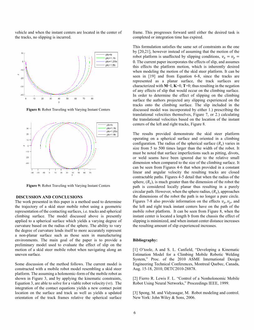
the tracks, no slipping is incurred.
DISCUSSION AND CONCLUSIONS
The work presented in this paper is a method used to determine
the trajectory of a skid steer mobile robot using a geometric
representation of the contacting surfaces, i.e. tracks and spherical
climbing surface. The model discussed above is presently
applied to a spherical surface which yields a varying degree of
curvature based on the radius of the sphere. The ability to vary
the degree of curvature lends itself to more accurately represent
a non-planar surface such as those seen in manufacturing
environments. The main goal of the paper is to provide a
preliminary model used to evaluate the effect of slip on the
motion of a skid steer mobile robot when navigating along an
uneven surface.
Some discussion of the method follows. The current model is
constructed with a mobile robot model resembling a skid steer
platform. The assuming a holonomic-form of the mobile robot as
shown in Figure 3, and by applying the kinematic constraints,
Equation 3, are able to solve for a viable robot velocity (vr). The
integration of the contact equations yields a new contact point
location on the surface and track as well as yields a updated
orientation of the track frames relative the spherical surface
frame. This progresses forward until either the desired task is
completed or integration time has expired.
This formulation satisfies the same set of constraints as the one
by [20,21], however instead of assuming that the motion of the
robot platform is unaffected by slipping conditions, 𝑣𝑥 = 𝑣𝑦 =
0. The current paper incorporates the effects of slip, and assumes
this effects the platform motion, which is inherently desired
when modeling the motion of the skid steer platform. It can be
seen in [19] and from Equation 6-8, since the tracks are
represented as a planar surface, the track surfaces are
characterized with M=I, K=0, T=0; thus resulting in the negation
of any effects of slip that would occur on the climbing surface.
In order to determine the effect of slipping on the climbing
surface the authors projected any slipping experienced on the
tracks onto the climbing surface. The slip included in the
discussed model was incorporated by either 1.) prescribing the
translational velocities themselves, Figure 7, or 2.) calculating
the translational velocities based on the location of the instant
centers of the left and right tracks, Figure 8.
The results provided demonstrate the skid steer platform
operating on a spherical surface and oriented in a climbing
configuration. The radius of the spherical surface (𝑅𝑠) varies in
size from 5 to 500 times larger than the width of the robot. It
must be noted that surface imperfections such as pitting, divots,
or weld seams have been ignored due to the relative small
dimension when compared to the size of the climbing surface. It
can be seen from Figures 4-6 that when provided in a constant
linear and angular velocity the resulting tracks are closed
contractable paths. Figures 4-5 detail that when the radius of the
sphere, (𝑅𝑠), is much greater than the dimension of the robot the
path is considered locally planar thus resulting in a purely
circular path. However, when the sphere radius, (𝑅𝑠), approaches
the dimensions of the robot the path is no longer a pure circle.
Figures 7-8 also provide information on the effects 𝑣𝑥 , 𝑣𝑦 , and
the left and right track instant centers have on the path of the
mobile robot platform. It can be seen from Figure 8, when the
instant center is located a length b from the chassis the effect of
slipping is minimized, and when instant center distance increases
the resulting amount of slip experienced increases.
Bibliography:
[1] O’toole, A and S. L. Canfield, “Developing a Kinematic
Estimation Model for a Climbing Mobile Robotic Welding
System,” Proc. of the 2010 ASME International Design
Engineering Technical Conferences, Montreal Quebec, Canada,
Aug. 15-18, 2010, DETC2010-28878.
[2] Fierro R. Lewis F. L. “Control of a Nonholonomic Mobile
Robot Using Neural Networks,” Proceedings IEEE, 1999.
[3] Spong, M. and Vidyasagar, M. Robot modeling and control.
New York: John Wiley & Sons, 2006.
Figure 8: Robot Traveling with Varying Instant Centers
Figure 9: Robot Traveling with Varying Instant Centers

7
[4] Wong, J. Y. and Huang, W. "Wheels vs. tracks–A fundamental
evaluation from the traction perspective." Journal of
Terramechanics 43.1 (2006): 27-42.
[5] Canfield, S. L. and J. W. Beard, "Robotic inspection in power
plants," ISA 51st Annual Instrumentation Symposium, 2005.
[6] Martínez, J. L. Mandow, A. Morales, J. Pedraza, S. and
Garcia-Cerezo, A. "Approximating kinematics for tracked
mobile robots, "The International Journal of Robotics Research
24.10 (2005): 867-878.
[7] Wong, J. Y., and Chiang, C. "A general theory for skid
steering of tracked vehicles on firm ground." Proceedings of the
Institution of Mechanical Engineers, Part D: Journal of
Automobile Engineering 215.3 (2001): 343-355.
[8] Agrawal , S. K. and Ryu, J.C. "Differential flatness-based
robust control of mobile robots in the presence of slip," The
International Journal of Robotics Research 30.4 (2011): 463-
475.
[9] Caracciolo, L. and De Luca, L. "Trajectory tracking control
of a four-wheel differentially driven mobile robot," Robotics and
Automation, 1999. Proceedings. 1999 IEEE International
Conference on. Vol. 4. IEEE, 1999.
[10] Kozłowski, K. and Pazderski, D. "Modeling and control of
a 4-wheel skid-steering mobile robot." Int. J. Appl. Math.
Comput. Sci 14.4 (2004): 477-496.
[11] Mandow, A. Martinez, J.L. Morales, J. Blanco, J. L. Garcia-
Cerezo, A. and Gonzalez J. "Experimental kinematics for
wheeled skid-steer mobile robots," Intelligent Robots and
Systems, 2007. IROS 2007. IEEE/RSJ International Conference
on. IEEE, 2007.
[12] Song, X. Seneviratne, L.D. Althoefer, K. Song, Z. "A robust
slip estimation method for skid-steered mobile robots." Control,
Automation, Robotics and Vision, 2008. ICARCV 2008. 10th
International Conference on. IEEE, 2008.
[13] Shiller, Z. and Hua, M. "Trajectory planning of tracked
vehicles." Robotics and Automation, 1993. Proceedings., 1993
IEEE International Conference on. IEEE, 1993.
[14] Yu, W. Chuy, O. Collins E. and Hollis P. Analysis and
Experimental Verification for Dynamic Modeling of A Skid-
Steered Wheeled Vehicle. IEEE Proceedings on Robotics, VOL.
26, NO. 2, APRIL 2010
[15] Mandow, A. Martínez, J. L. Morales, J. Blanco, J. L. Garcia-
Cerezo, A. and Gonzalez J. "Experimental kinematics for
wheeled skid-steer mobile robots."Intelligent Robots and
Systems, 2007. IROS 2007. IEEE/RSJ International Conference
on. IEEE, 2007.
[16] Sarkar, N. and Kumar, V. "Control of Mechanical Systems
With Rolling Constraints Application to Dynamic Control of
Mobile Robots," The International Journal of Robotics Research
13.1 (1994): 55-69.
[17] Sarkar, N., X. Yun and V. Kumar, "Dynamic Control of 3-D
Rolling Contacts in Two-Arm Manipulation." IEEE Transactions
on Robotics and Automation, Vol. 13(3), (1997), pp. 364 – 376
[18] Chakraborty, N. Ghosal, A. Kinematics of wheeled mobile
robots on uneven terrain, Mechanism and Machine Theory 39
(2004) 1273-1287
[19] Montana, D.J. The kinematics of contact and grasp, Int. J.
Rob. Res. 7 (3) (1988) 17–32.
[20] Caccavale, Fabrizio, et al. "Grasp planning and parallel
control of a redundant dual-arm/hand manipulation
system." Robotica 31.07 (2013): 1169-1194.
[21] Qualls, J. Canfield, S. Hill, T. Shibakov, A. ASME 2015
International Design Engineering Technical Conferences and
Computers and Information in Engineering ConferenceVolume
5A: 39th Mechanisms and Robotics Conference Boston,
Massachusetts, USA, August 2–5, 2015
[22] Qualls, Joshua E. "Kinematic Analysis and Control of a
Mobile Robot Performing Manufacturing Tasks on Non-Planar
Surfaces using Differential Geometry." Order No. 1605525
Tennessee Technological University, 2015. Ann
Arbor: ProQuest.Web. 16 Feb. 2016.