draft - kopykitab
TRANSCRIPT


Draft
Chapter 1
INTRODUCTION
1.1 Structural Engineering
1 Structural engineers are responsible for the detailed analysis and design of:
Architectural structures: Buildings, houses, factories. They must work in close cooperation with anarchitect who will ultimately be responsible for the design.
Civil Infrastructures: Bridges, dams, pipelines, offshore structures. They work with transportation,hydraulic, nuclear and other engineers. For those structures they play the leading role.
Aerospace, Mechanical, Naval structures: aeroplanes, spacecrafts, cars, ships, submarines to en-sure the structural safety of those important structures.
1.2 Structures and their Surroundings
2 Structural design is affected by various environmental constraints:
1. Major movements: For example, elevator shafts are usually shear walls good at resisting lateralload (wind, earthquake).
2. Sound and structure interact:
• A dome roof will concentrate the sound
• A dish roof will diffuse the sound
3. Natural light:
• A flat roof in a building may not provide adequate light.
• A Folded plate will provide adequate lighting (analysis more complex).
• A bearing and shear wall building may not have enough openings for daylight.
• A Frame design will allow more light in (analysis more complex).
4. Conduits for cables (electric, telephone, computer), HVAC ducts, may dictate type of floor system.
5. Net clearance between columns (unobstructed surface) will dictate type of framing.
1.3 Architecture & Engineering
3 Architecture must be the product of a creative collaboration of architects and engineers.
4 Architect stress the overall, rather than elemental approach to design. In the design process, theyconceptualize a space-form scheme as a total system. They are generalists.

Draft1–2 INTRODUCTION
5 The engineer, partly due to his/her education think in reverse, starting with details and withoutsufficient regards for the overall picture. (S)he is a pragmatist who “knows everything about nothing”.
6 Thus there is a conceptual gap between architects and engineers at all levels of design.
7 Engineer’s education is more specialized and in depth than the architect’s. However, engineer mustbe kept aware of overall architectural objective.
8 In the last resort, it is the architect who is the leader of the construction team, and the engineers arehis/her servant.
9 A possible compromise might be an Architectural Engineer.
1.4 Architectural Design Process
10 Architectural design is hierarchical:
Schematic: conceptual overall space-form feasibility of basic schematic options. Collaboration is mostlybetween the owner and the architect.
Preliminary: Establish basic physical properties of major subsystems and key components to provedesign feasibility. Some collaboration with engineers is necessary.
Final design: final in-depth design refinements of all subsystems and components and preparation ofworking documents (“blue-prints”). Engineers play a leading role.
1.5 Architectural Design
11 Architectural design must respect various constraints:
Functionality: Influence of the adopted structure on the purposes for which the structure was erected.
Aesthetics: The architect often imposes his aesthetic concerns on the engineer. This in turn can placesevere limitations on the structural system.
Economy: It should be kept in mind that the two largest components of a structure are labors andmaterials. Design cost is comparatively negligible.
1.6 Structural Analysis
12 Given an existing structure subjected to a certain load determine internal forces (axial, shear, flex-ural, torsional; or stresses), deflections, and verify that no unstable failure can occur.
13 Thus the basic structural requirements are:
Strength: stresses should not exceed critical values: σ < σf
Stiffness: deflections should be controlled: ∆ < ∆max
Stability: buckling or cracking should also be prevented
1.7 Structural Design
14 Given a set of forces, dimension the structural element.
Steel/wood Structures Select appropriate section.
Reinforced Concrete: Determine dimensions of the element and internal reinforcement (number andsizes of reinforcing bars).
Victor Saouma Structural Engineering

Draft1.8 Load Transfer Elements 1–3
15 For new structures, iterative process between analysis and design. A preliminary design is madeusing rules of thumbs (best known to Engineers with design experience) and analyzed. Followingdesign, we check for
Serviceability: deflections, crack widths under the applied load. Compare with acceptable valuesspecified in the design code.
Failure: and compare the failure load with the applied load times the appropriate factors of safety.
If the design is found not to be acceptable, then it must be modified and reanalyzed.
16 For existing structures rehabilitation, or verification of an old infrastructure, analysis is the mostimportant component.
17 In summary, analysis is always required.
1.8 Load Transfer Elements
18 From Strength of Materials, Fig. 1.1
Figure 1.1: Types of Forces in Structural Elements (1D)
Axial: cables, truss elements, arches, membrane, shells
Flexural: Beams, frames, grids, plates
Torsional: Grids, 3D frames
Shear: Frames, grids, shear walls.
1.9 Structure Types
19 Structures can be classified as follows:
Victor Saouma Structural Engineering

Draft1–4 INTRODUCTION
Tension & Compression Structures: only, no shear, flexure, or torsion
Cable (tension only): The high strength of steel cables, combined with the efficiency of simpletension, makes cables ideal structural elements to span large distances such as bridges, anddish roofs, Fig. 1.2
Figure 1.2: Basic Aspects of Cable Systems
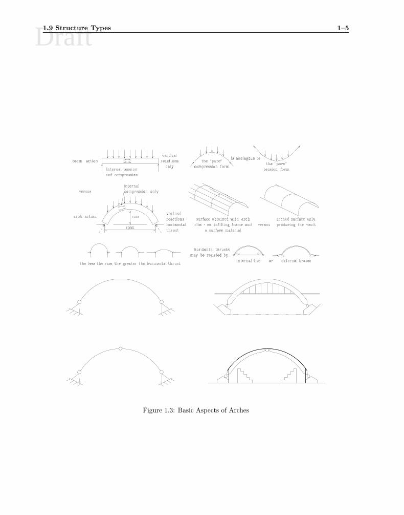
Arches (mostly compression) is a “reversed cable structure”. In an arch, we seek to minimizeflexure and transfer the load through axial forces only. Arches are used for large span roofsand bridges, Fig. 1.3
Trusses have pin connected elements which can transmit axial forces only (tension and com-pression). Elements are connected by either slotted, screwed, or gusset plate connectors.However, due to construction details, there may be secondary stresses caused by relativelyrigid connections. Trusses are used for joists, roofs, bridges, electric tower, Fig. 1.4
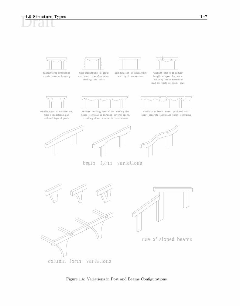
Post and Beams: Essentially a support column on which a “beam” rests, Fig. 1.5, and 1.6.
Victor Saouma Structural Engineering
Draft1.9 Structure Types 1–5
Figure 1.3: Basic Aspects of Arches
Victor Saouma Structural Engineering

Draft1–6 INTRODUCTION
Figure 1.4: Types of Trusses
Victor Saouma Structural Engineering
Draft1.9 Structure Types 1–7
Figure 1.5: Variations in Post and Beams Configurations
Victor Saouma Structural Engineering

Draft1–8 INTRODUCTION
OVERLAPPING SINGLE-STRUTCABLE-SUPPORTED BEAM
CABLE-STAYED BEAM
BRACED BEAM
VIERENDEEL TRUSS TREE-SUPPORTED TRUSS
CABLE-SUPPORTEDMULTI-STRUT
BEAM OR TRUSS
CABLE-SUPPORTED PORTAL FRAMECABLE-SUPPORTED ARCHED FRAME
SUSPENDED CABLESUPPORTED BEAM
CABLE-SUPPORTEDSTRUTED ARCH OR
CABLE BEAM/TRUSS
GABLED TRUSS
BOWSTRING TRUSS
Figure 1.6: Different Beam Types
Victor Saouma Structural Engineering

Draft1.9 Structure Types 1–9
Beams: Shear, flexure and sometimes axial forces. Recall that σ = McI is applicable only for shallow
beams, i.e. span/depth at least equal to five.
Whereas r/c beams are mostly rectangular or T shaped, steel beams are usually I shaped (if thetop flanges are not properly stiffened, they may buckle, thus we must have stiffeners).
Frames: Load is co-planar with the structure. Axial, shear, flexure (with respect to one axis in 2Dstructures and with respect to two axis in 3D structures), torsion (only in 3D). The frame iscomposed of at least one horizontal member (beam) rigidly connected to vertical ones1. The verticalmembers can have different boundary conditions (which are usually governed by soil conditions).Frames are extensively used for houses and buildings, Fig. 1.7.
Figure 1.7: Basic Forms of Frames
Grids and Plates: Load is orthogonal to the plane of the structure. Flexure, shear, torsion.
In a grid, beams are at right angles resulting in a two-way dispersal of loads. Because of the rigidconnections between the beams, additional stiffness is introduced by the torsional resistance ofmembers.
Grids can also be skewed to achieve greater efficiency if the aspect ratio is not close to one.
Plates are flat, rigid, two dimensional structures which transmit vertical load to their supports.Used mostly for floor slabs.
Folded plates is a combination of transverse and longitudinal beam action. Used for long spanroofs. Note that the plate may be folded circularly rather than longitudinally. Folded plates areused mostly as long span roofs. However, they can also be used as vertical walls to support bothvertical and horizontal loads.
1The precursor of the frame structures were the Post and Lintel where the post is vertical member on which the lintelis simply posed.
Victor Saouma Structural Engineering

Draft1–10 INTRODUCTION
Membranes: 3D structures composed of a flexible 2D surface resisting tension only. They are usuallycable-supported and are used for tents and long span roofs Fig. 1.8.
Figure 1.8: Examples of Air Supported Structures
Shells: 3D structures composed of a curved 2D surface, they are usually shaped to transmit compressiveaxial stresses only, Fig. 1.9.
Shells are classified in terms of their curvature.
1.10 Structural Engineering Courses
20 Structural engineering education can be approached from either one of two points of views:
Architectural: Start from overall design, and move toward detailed analysis.
Education: Elemental rather than global approach. Emphasis is on the individual structural elementsand not always on the total system.
CVEN3525 will seek a balance between those two approaches.
21 This is only the third of a long series of courses which can be taken in Structural Engineering, Fig.1.10
Victor Saouma Structural Engineering

Draft1.10 Structural Engineering Courses 1–11
Figure 1.9: Basic Forms of Shells
Figure 1.10: Sequence of Structural Engineering Courses
Victor Saouma Structural Engineering

Draft1–12 INTRODUCTION
1.11 References
22 Following are some useful references for structural engineering, those marked by † were consulted,and “borrowed from” in preparing the Lecture Notes:
Structural Art
1. Billington, D.P., The Tower and the Bridge; The new art of structural engineering, PrincetonUniversity Pres,, 1983.
Structural Engineering
1. Biggs, J.M., Introduction to Structural Engineering; Analysis and Design, Prentice Hall, 1986.
2. Gordon, J.E., Structures, or Why Things Do’nt Fall Down, Da Capo paperback, New York,1978
3. Mainstone, R., Developments in Structural Form, Allen Lane Publishers, 1975.
Structural Engineering, Architectural Analysis and Design
1. Ambrose, J., Building Structures, second Ed. Wiley, 1993.
2. Salvadori, M. and Heller, R., Structure in Architecture; The Building of Buildings, PrenticeHall, Third Edition, 1986.
3. Salvadori, M. and Levy, M., Structural Design in Architecture, Prentice hall, Second Edition,1981.
4. Salvadori, M.,Why Buildings Stand Up; The Strength of Architecture, Norton Paperack, 1990.
5. Lin, T.Y. and Stotesbury, S.D., Structural Concepts and Systems for Architects and Engineers,John Wiley, 1981.
6. † White, R. Gergely, P. and Sexmith, R., Structural Engineering; Combined Edition, JohnWiley, 1976.
7. Sandaker, B.N. and Eggen, A.P., The Structural Basis of Architecture, Whitney Library ofDesign, 1992.
Structural Analysis
1. † Arbadi, F. Structural Analysis and Behavior, McGraw-Hill, Inc., 1991.
2. Hsieh, Y.Y., Elementary Theory of Structures, Third Edition, Prentice Hall, 1988.
3. Ghali, A., and Neville, A.M., Structural Analysis, Third Edition, Chapman and Hall, 1989
Structural Design
1. † Nilson, A., and Winter, G. Design of Concrete Structures, Eleventh Edition, McGraw Hill,1991.
2. † Salmon C. and Johnson, J. Steel Structures, Third Edition, Harper Collins Publisher, 1990.
3. † Gaylord, E.H., Gaylord, C.N. and Stallmeyer, J.E., Design of Steel Structures, Third Edi-tion, McGraw Hill, 1992.
Codes
1. ACI-318-89, Building Code Requirements for Reinforced Concrete, American Concrete Insti-tute
2. Load & Resistance Factor Design, Manual of Steel Construction, American Institute of SteelConstruction.
3. Uniform Building Code, International Conference of Building Officials, 5360 South WorkmanRoad; Whittier, CA 90601
4. Minimum Design Loads in Buildings and Other Structures, ANSI A58.1, American NationalStandards Institute, Inc., New York, 1972.
Victor Saouma Structural Engineering

Draft
Chapter 2
LOADS
2.1 Introduction
1 The main purpose of a structure is to transfer load from one point to another: bridge deck to pier;slab to beam; beam to girder; girder to column; column to foundation; foundation to soil.
2 There can also be secondary loads such as thermal (in restrained structures), differential settlementof foundations, P-Delta effects (additional moment caused by the product of the vertical force and thelateral displacement caused by lateral load in a high rise building).
3 Loads are generally subdivided into two categories
Vertical Loads or gravity load
1. dead load (DL)
2. live load (LL)
also included are snow loads.
Lateral Loads which act horizontally on the structure
1. Wind load (WL)
2. Earthquake load (EL)
this also includes hydrostatic and earth loads.
4 This distinction is helpful not only to compute a structure’s load, but also to assign different factor ofsafety to each one.
5 For a detailed coverage of loads, refer to the Universal Building Code (UBC), (UBC 1995).
2.2 Vertical Loads
6 For closely spaced identical loads (such as joist loads), it is customary to treat them as a uniformlydistributed load rather than as discrete loads, Fig. 2.1
2.2.1 Dead Load
7 Dead loads (DL) consist of the weight of the structure itself, and other permanent fixtures (such aswalls, slabs, machinery).
8 For analysis purposes, dead loads can easily be determined from the structure’s dimensions and density,Table 2.1

Draft2–2 LOADS
P P P P P P P1 2 3 4 5 6 7
TYPICAL SYSTEM OF JOISTS
SUPPORT BEAM
REPETITIVE JOIST LOADS
ACTUAL DISCRETE LOADS ON SUPPORT BEAM
ASSUMED EQUIVALENT UNIFORM LOAD
w LB/FT = TOTAL LOAD / SPAN
SPAN
Figure 2.1: Approximation of a Series of Closely Spaced Loads
Material lb/ft3 kN/m3
Aluminum 173 27.2Brick 120 18.9Concrete 145 33.8Steel 490 77.0Wood (pine) 40 6.3
Table 2.1: Unit Weight of Materials
9 For steel structures, the weight per unit length of rolled sections is given in the AISC Manual of SteelConstruction.
10 For design purposes, dead loads must be estimated and verified at the end of the design cycle. Thismakes the design process iterative.
11 Weights for building materials is given in Table 2.2
12 For preliminary design purposes the average dead loads of Table 2.3 can be used:
2.2.2 Live Loads
13 Contrarily to dead loads which are fixed and vertical, live loads (LL) are movable or moving and maybe horizontal.
14 Occupancy load may be due to people, furniture, equipment. The loads are essentially variable pointloads which can be placed anywhere.
15 In analysis load placement should be such that their effect (shear/moment) are maximized.
16 A statistical approach is used to determine a uniformly distributed static load which is equivalent tothe weight of the maximum concentration of occupants. These loads are defined in codes such as theUniform Building Code or the ANSI Code, Table 2.4.
17 For small areas (30 to 50 sq ft) the effect of concentrated load should be considered separately.
18 Since there is a small probability that the whole floor in a building be fully loaded, the UBC codespecifies that the occupancy load for members supporting an area A larger than 150 ft2 (i.e. a columnwith a total tributary area, including floors above it, larger than 150 ft2) may be reduced by R where
R = r(A − 150) ≤ 23.1(1 +
DL
LL
)(2.1)
Victor Saouma Structural Engineering

JNTU Study Material For StructuralAnalysis-I (Civil Engineering)
Publisher : Faculty Notes Author : Panel Of Experts
Type the URL : http://www.kopykitab.com/product/10176
Get this eBook
50%OFF