draft no. 1 - ulisboaweb.ist.utl.pt/~guilherme.f.silva/ec/ec4 - design... · 1.6.2 greek upper case...
TRANSCRIPT

Title Page Draft prEN 1994-2:2003
EUROPEAN STANDARD EN 1994-2 NORME EUROPÉENNE EUROPÄISCHE NORM
English version
EN 1994 Design of composite steel and concrete structures
Part 2 Bridges
CEN
European Committee for Standardization Comité Européen de Normalisation Europäisches Komitee für Normung
DRAFT No. 1 including general rules from prEN 1994-1-1 draft 3
Central Secretariat: rue de Stassart 36, B-1050 Brussels © CEN 1994 Copyright reserved to all CEN members Ref.No …….. 2001-10-26

Contents
Foreword Section 1 General 1.1 Scope 1.1.1 Scope of Eurocode 4 1.1.2 Scope of Part 1.1 of Eurocode 4 1.1.3 Further Parts of Eurocode 4 1.1.4 Scope of Part 2 of Eurocode 1994 1.2 Normative references 1.2.1 General reference standards 1.2.2 Other reference standards 1.3 Assumptions 1.4 Distinction between principles and application rules 1.5 Definitions 1.5.1 Terms common to all Eurocodes 1.5.2 Terms used in EN 1994 1.5.3 Special terms used in Part 2 of Eurocode EN 1994 1.5.4 Other definitions 1.6 Symbols 1.6.1 Latin upper case letters 1.6.2 Greek upper case letters 1.6.3 Latin lower case letters 1.6.4 Greek lower case letters 1.6.5 Subscripts 1.6.6 Use of subscripts in Part 1.1 of Eurocode 4 1.6.7 Conventions for member axes Section 2 Basis of design 2.2 Definitions and classifications 2.2.1 Limit states and design situations 2.2.1.1 Limit states 2.2.1.2 Design situations 2.2.2 Actions 2.2.2.2 Characteristic values of actions 2.2.2.3 Representative values of variable actions 2.2.2.4 Design values of actions 2.2.5 Load arrangements and load cases 2.3 Design requirements 2.3.1 General 2.3.2.1 Verification conditions 2.3.2.2 Combinations of actions 2.3.2.3 Design values of permanent actions 2.3.2.4 Verification of static equilibrium 2.3.3.1 Partial safety factors for actions on bridge structures 2.3.3.2 Partial safety factors for resistances and material properties

2.3.4 Serviceability limit states 2.4 Durability Section 3 Materials 3.1 Concrete 3.2 Reinforcing steel 3.3 Structural steel 3.4 Connecting devices 3.4.1 General 3.4.2 Stud shear connectors 3.6 Prestressing steel and devices Section 4 Durability 4.1 General 4.2 Corrosion protection at the steel-concrete interface in bridges Section 5 Structural analysis 5.1 Structural modelling for analysis 5.1.1 Structural modelling and basic assumptions 5.1.2 Joint modelling 5.1.3 Ground-structure interaction 5.2 Structural stability 5.2.1 Effects of deformed geometry of the structure 5.3 Imperfections 5.3.1 Basis 5.3.2 Imperfections for bridges 5.4 Calculation of action effects 5.4.1 Methods of global analysis 5.4.1.1 General 5.4.1.2 Effective width of flanges for shear lag 5.4.2 Linear elastic analysis 5.4.2.1 General 5.4.2.2 Stiffness assumptions 5.4.2.3 Creep and Shrinkage 5.4.2.4 Effects of cracking of concrete 5.4.2.5 Stages and sequence of construction 5.4.2.6 Temperature effects 5.4.2.7 Prestressing by controlled imposed deformaton 5.4.2.8 Prestressing by tendons 5.4.2.9 Tension members in composite bridges 5.4.210 Filler beam decks for bridges 5.4.3 Non linear global analysis 5.5 Classification of cross-sections 5.5.1 General 5.5.1.1 Classification of sections of filler beam decks for bridges

Section 6 Ultimate limit states 6.1 Beams 6.1.1 Beams for bridges 6.1.2 Effective width for verification of cross-sections 6.2 Resistances of cross-sections of beams 6.2.1 Bending resistance 6.2.2 Resistance to vertical shear 6.3 Filler beam decks 6.3.1 General 6.3.2 Bending moments 6.3.3 Vertical shear 6.3.4 Resistance and stability of steel beams during execution 6.3.5 Half-through bridges with transverse filler beams 6.4 Lateral-torsional buckling of composite beams 6.4.1 General 6.4.2 Verification of lateral-torsional buckling of uniform composite beams with
cross-sections in Class 1 or 2 6.4.3 Effects of transverse frames in bridges 6.5 Transverse forces on webs 6.5.1 General 6.5.2 Flange-induced buckling of webs 6.6 Shear connection 6.6.1 General 6.6.2 Longitudinal shear force in beams 6.6.3 Headed stud connectors in solid slabs and concrete encasement 6.6.4 Angle connectors 6.6.5 Detailing of the shear connection 6.6.6 Transverse reinforcement 6.7 Composite columns and composite compression members 6.7.1 General 6.7.2 General method of design 6.7.3 Simplified method of design 6.7.4 Shear connection and load introduction 6.7.5 Detailing provisions 6.8 Fatigue 6.8.1 General 6.8.2 Partial safety factors for fatigue assesment 6.8.3 Fatigue strength 6.8.4 Internal forces and stresses for fatigue verification 6.8.5 Fatigue assessment based on nominal stress ranges 6.9 Tension members in composite bridges Section 7, Serviceability limit states 7.1 General 7.1.1 Scope 7.2 Stresses 7.2.1 General 7.2.2 Stress limitation for bridges

7.3 Deformations 7.3.1 General 7.3.2 Beams in bridges 7.3.3 Vibration 7.4 Cracking of concrete 7.4.1 General 7.4.2 Minimum reinforcement 7.4.3 Control of cracking due to direct loading 7.5 Filler beam decks 7.5.1 General 7.5.2 Cracking of concrete 7.5.3 Minimum reinforcement 7.5.4 Control of cracking due to direct loading Section 8 Decks with precast concrete slabs 8.1 General 8.2 Actions 8.3 Design, analysis and detailing of the bridge slab 8.4 Joints between steel beam and concrete slab 8.4.1 Bedding and tolerances 8.4.2 Corrosion 8.4.3 Shear connection and transverse reinforcement Section 9 Composite plates in bridges 9.1 General 9.2 Design for local effects 9.3 Design for global effects 9.4 Design of shear connectors Section 10 Execution 10.2 Sequence of construction 10.3 Accuracy during construction, and quality control 10.4.1 Deflection during and after concreting 10.4.2 Shear connection 10.4.3.1 Headed studs 10.4.3.2 Hoops and block connectors 10.4.3.3 Friction grip bolts 10.4.3.4 Corrosion protection in the interface 10.4.3.5 Surface condition Section 11 Standard tests 11.1 General 11.2 Tests on shear connectors 11.2.1 General 11.2.2 Testing arrangements 11.2.3 Preparation of specimens

11.2.4 Testing procedure 11.2.5 Test evaluation

Draft 1 Page 1 2001–MM-DD prEN 1994-2: 200X
Paper BK-005/10/25/01
Foreword [Drafting Note: The Foreword is drafted independently from Part 1} This European Standard EN 1994-2, Eurocode : Design of composite steel and concrete structures – Part 2 Bridges, has been prepared on behalf of Technical Committee CEN/TC250 « Structural Eurocodes », the Secretariat of which is held by BSI. CEN/TC250 is responsible for all Structural Eurocodes.
The text of the draft standard was submitted to the formal vote and was approved by CEN as EN 199X-X-X on YYYY-MM-DD. No existing European Standard is superseded.
Background of the Eurocode programme In 1975, the Commission of the European Community decided on an action programme in the field of construction, based on article 95 of the Treaty. The objective of the programme was the elimination of technical obstacles to trade and the harmonisation of technical specifications. Within this action programme, the Commission took the initiative to establish a set of harmonised technical rules for the design of construction works which, in a first stage, would serve as an alternative to the national rules in force in the Member States and, ultimately, would replace them. For fifteen years, the Commission, with the help of a Steering Committee with Representatives of Member States, conducted the development of the Eurocodes programme, which led to the first generation of European codes in the 1980s. In 1989, the Commission and the Member States of the EU and EFTA decided, on the basis of an agreement1 between the Commission and CEN, to transfer the preparation and the publication of the Eurocodes to CEN through a series of Mandates, in order to provide them with a future status of European Standard (EN). This links de facto the Eurocodes with the provisions of all the Council’s Directives and/or Commission’s Decisions dealing with European standards (e.g. the Council Directive 89/106/EEC on construction products - CPD - and Council Directives 93/37/EEC, 92/50/EEC and 89/440/EEC on public works and services and equivalent EFTA Directives initiated in pursuit of setting up the internal market). The Structural Eurocode programme comprises the following standards generally consisting of a number of Parts: EN 1990 Eurocode : Basis of Structural Design EN 1991 Eurocode 1: Actions on structures EN 1992 Eurocode 2: Design of concrete structures EN 1993 Eurocode 3: Design of steel structures EN 1994 Eurocode 4: Design of composite steel and concrete structures EN 1995 Eurocode 5: Design of timber structures EN 1996 Eurocode 6: Design of masonry structures EN 1997 Eurocode 7: Geotechnical design EN 1998 Eurocode 8: Design of structures for earthquake resistance EN 1999 Eurocode 9: Design of aluminium structures
1 Agreement between the Commission of the European Communities and the European Committee for Standardisation (CEN) concerning the work on EUROCODES for the design of
building and civil engineering works (BC/CEN/03/89).

Draft 1 Page 2 2001–MM-DD prEN 1994-2: 200X
Paper BK-005/10/25/01
Eurocode standards recognise the responsibility of regulatory authorities in each Member State and have safeguarded their right to determine values related to regulatory safety matters at national level where these continue to vary from State to State.
Status and field of application of Eurocodes The Member States of the EU and EFTA recognise that Eurocodes serve as reference documents for the following purposes: – as a means to prove compliance of building and civil engineering works with the essential
requirements of Council Directive 89/106/EEC, particularly Essential Requirement N°1 – Mechanical resistance and stability – and Essential Requirement N°2 – Safety in case of fire ;
– as a basis for specifying contracts for construction works and related engineering services ; – as a framework for drawing up harmonised technical specifications for construction products (ENs
and ETAs) The Eurocodes, as far as they concern the construction works themselves, have a direct relationship with the Interpretative Documents2 referred to in Article 12 of the CPD, although they are of a different nature from harmonised product standards3. Therefore, technical aspects arising from the Eurocodes work need to be adequately considered by CEN Technical Committees and/or EOTA Working Groups working on product standards with a view to achieving full compatibility of these technical specifications with the Eurocodes. The Eurocode standards provide common structural design rules for everyday use for the design of whole structures and component products of both a traditional and an innovative nature. Unusual forms of construction or design conditions are not specifically covered and additional expert consideration will be required by the designer in such cases.
National Standards implementing Eurocodes The National Standards implementing Eurocodes will comprise the full text of the Eurocode (including any annexes), as published by CEN, which may be preceded by a National title page and National foreword, and may be followed by a National annex. The National annex may only contain information on those parameters which are left open in the Eurocode for national choice, known as Nationally Determined Parameters, to be used for the design of buildings and civil engineering works to be constructed in the country concerned, i.e.: - values and/or classes where alternatives are given in the Eurocode, - values to be used where a symbol only is given in the Eurocode, - country specific data (geographical, climatic, etc.), e.g. snow map, - the procedure to be used where alternative procedures are given in the Eurocode. It may also contain - decisions on the use of informative annexes, and - references to non-contradictory complementary information to assist the user to apply the Eurocode.
Links between Eurocodes and harmonised technical specifications (ENs and ETAs) for products 2 According to Art. 3.3 of the CPD, the essential requirements (ERs) shall be given concrete form in interpretative documents for the creation of the necessary links between the essential
requirements and the mandates for harmonised ENs and ETAGs/ETAs. 3 According to Art. 12 of the CPD the interpretative documents shall : a) give concrete form to the essential requirements by harmonising the terminology and the technical bases and indicating classes or levels for each requirement where necessary ; b) indicate methods of correlating these classes or levels of requirement with the technical specifications, e.g. methods of calculation and of proof, technical rules for project design, etc . ; c) serve as a reference for the establishment of harmonised standards and guidelines for European technical approvals. The Eurocodes, de facto, play a similar role in the field of the ER 1 and a part of ER 2.

Draft 1 Page 3 2001–MM-DD prEN 1994-2: 200X
Paper BK-005/10/25/01
There is a need for consistency between the harmonised technical specifications for construction products and the technical rules for works4. Furthermore, all the information accompanying the CE Marking of the construction products which refer to Eurocodes shall clearly mention which Nationally Determined Parameters have been taken into account.
Additional information specific to EN 1994-2 EN 1994-2 gives Principles and application rules for the design of composite steel and concrete bridges or composite members of bridges. EN 1994-2 is intended for use by clients, designers, contractors and public authorities. EN 1994-2 is intended to be used with EN 1990, the relevant parts of EN 1991, EN 1993 for the design of steel structures and EN 1992 for the design of concrete structures.
National annex for EN 1994-2 This standard gives alternative procedures, values and recommendations for classes with notes indicating where national choices may have to be made. Therefore the National Standard implementing EN 1994-2 should have a National annex containing all Nationally Determined Parameters to be used for the design of bridges to be constructed in the relevant country.
National choice is allowed in EN 1994-2 through clauses: [Drafting Note: Clause numbers to be inserted]
4 see Art.3.3 and Art.12 of the CPD, as well as clauses 4.2, 4.3.1, 4.3.2 and 5.2 of ID 1.

Draft 1 Page 4 2001–MM-DD prEN 1994-2: 200X
Paper BK-005/10/25/01
1 General
1.1 Scope
1.1.1 Scope of Eurocode 4 (1)P Eurocode 4 applies to the design of composite structures and members for buildings and civil engineering works. The composite structures and members are made of structural steel and reinforced or prestressed concrete connected together to resist loads. Eurocode 4 is subdivided into various separate parts, see 1.1.2 and 1.1.3.
(2)P This Eurocode is only concerned with the requirements for resistance, serviceability and durability of structures. Other requirements, e.g. concerning thermal or sound insulation, are not considered. (3)P Execution is covered in Section 10 and by reference to other European Standards, to the extent that it is necessary to indicate the quality of the construction materials and products, that should be used and the standard of workmanship needed to comply with the assumptions of the design rules. Generally, the provisions related to execution are to be considered as minimum requirements which may have to be further developed for particular types of buildings or civil engineering works and methods of construction. (4)P Eurocode 4 does not cover the special requirements of seismic design. Provisions related to such requirements are given in Eurocode 8 “Design of structures for earthquake resistance” which complements, and is consistent with, Eurocode 4. (5)P Numerical values of the actions on buildings and civil engineering works to be taken into account in the design are given in Eurocode 1 "Actions on structures" applicable to the various types of construction.
1.1.2 Scope of Part 1.1 of Eurocode 4 (1)P Part 1.1 of Eurocode 4 gives a general basis for the design of composite structures together with specific provisions for buildings .
(2)P In addition, Part 1.1 gives detailed application rules which are mainly applicable to ordinary buildings. The applicability of these rules may be limited, for practical reasons or due to simplifications; their use and any limits of applicability are explained in the text where necessary. (3)P The following subjects are dealt with in Part 1.1: - Section 1 : General - Section 2 : Basis of design - Section 3 : Materials - Section 4 : Durability - Section 5 : Structural analysis - Section 6 : Ultimate limit states - Section 7 : Serviceability limit states - Section 8 : Composite joints in frames for buildings - Section 9 : Composite slabs with profiled steel sheeting for buildings - Section 10 : Execution - Section 11 : Standard tests. (4)P Sections 1 and 2 provide additional clauses to those given in EN 1990:200x “Basis of design”.
(5)P Part 1.1 of Eurocode 4 shall in all cases be used in conjunction with relevant Parts of Eurocode 2 and Eurocode 3.

Draft 1 Page 5 2001–MM-DD prEN 1994-2: 200X
Paper BK-005/10/25/01
1.1.3 Further Parts of Eurocode 4 (1)P This Part 1.1 of Eurocode 4 is supplemented by further Parts which complement or adapt it for particular aspects of special types of civil engineering works and certain other aspects of design which are of general practical importance.
(2)P Further Parts of Eurocode 4 are : Part 1.2 : Structural fire design Part 2 : Bridges.
1.1.4 Scope of Part 2 of Eurocode 1994 (1)P The Part 2 of Eurocode 1994 gives basic design rules for steel-concrete composite bridges or members of bridges. (2) The provisions of Part 2 do not cover fully the use of unbonded tendons and the design of cable
stayed bridges. (3) Provisions for shear connection are given only for welded headed studs.
NOTE: Guidance for other types of shear connectors may be given in the National Annex (4) The following subjects are dealt with in Part 2:
Section 1: General
Section 2: Basis of design
Section 3: Materials
Section 4: Durability
Section 5: Structural analysis
Section 6: Ultimate limit states
Section 7: Serviceability limit states
Section 8: Decks with precast concrete slabs
Section 9: Composite plates in bridges
Section 10: Execution
Section 11: Standard tests
1.2 Normative references (1)P The following normative documents contain provisions which, through references in this text, constitutive provisions of this European standard. For dated references, subsequent amendments to or revisions of any of these publications do not apply. However, parties to agreements based on this European standard are encouraged to investigate the possibility of applying the most recent editions of the normative documents indicated below. For undated references the latest edition of the normative document referred to applies.
1.2.1 General reference standards
[Drafting Note: from updated Part 1]
1.2.2 Other reference standards
[Drafting Note: wait for updated Part 1]

Draft 1 Page 6 2001–MM-DD prEN 1994-2: 200X
Paper BK-005/10/25/01
1.3 Assumptions (1)P In addition to the general assumptions of EN 1990 the following assumptions apply: [Drafting Note: to be discussed]
1.4 Distinction between principles and application rules (1)P The rules in EN 1990 clause 1.4 apply.
1.5 Definitions
1.5.1 Terms common to all Eurocodes (1)P The rules in EN 1990 1.5 apply
1.5.2 Terms used in EN 1994 [Drafting Note: from updated Part 1]
1.5.3 Special terms used in Part 2 of Eurocode EN 1994 1(P) frame A structure or portion of a structure, comprising an assembly of directly connected structural members, designed to act together to resist load. This term covers both plane frames and three-dimensional frames. 2(P) filler beam deck A deck consisting of a concrete slab reinforced by encased steel beams, having their bottom flange on the level of the slab bottom, and by reinforcing steel. 3(P) composite member A structural member with components of concrete and of structural or cold-formed steel, interconnected by shear connection so as to limit the longitudinal slip between concrete and steel and the separation of one component from the other. 4(P) composite bridge A bridge in which at least some of the principal members are composite members. 5(P) composite column A composite member subjected mainly to compression and bending. Only columns with cross-sections of the types defined in 4.8.1 are treated in this Eurocode. 6(P) composite beam A composite member subjected mainly to bending. 7(P) composite plate Composite member, consisting of a nominally flat steel plate connected to a site cast concrete slab.
1.5.4 Other definitions [Drafting Note: Check parts 2 of EN1992 and EN1993]

Draft 1 Page 7 2001–MM-DD prEN 1994-2: 200X
Paper BK-005/10/25/01
1.6 Symbols (1)P For the purpose of this standard the following symbols apply.
1.6.1 Latin upper case letters A Accidental action A Area C Fixed value C Factor E Effect of actions E Modulus of elasticity F Action F Force G Permanent action G Shear modulus I Second moment of area K Stiffness factor (I/L) L Length; Span; System length M Moment in general M Bending moment N Axial force N Number of shear connectors P Shear resistance of a shear connector Q Variable action R Resistance S Internal forces and moments (with subscripts d or k) S Stiffness V Shear force W Section modulus X Value of a property of a material
1.6.2 Greek upper case letters ∆ Difference in ...(precedes main symbol)
1.6.3 Latin lower case letters a Distance; Geometrical data b Width; Breadth c Distance; Outstand c Thickness of concrete cover d Diameter; Depth e Eccentricity f Strength (of a material) h Height i Radius of gyration k Coefficient; Factor l Length; Span; Buckling length m Factor for composite slabs n Modular ratio r Radius s Spacing; Distance t Thickness v Shear force per unit length w Crack width xx, yy, zz Rectangular axes

Draft 1 Page 8 2001–MM-DD prEN 1994-2: 200X
Paper BK-005/10/25/01
1.6.4 Greek lower case letters α Angle; Ratio; Factor α Coefficient of linear thermal expansion β Angle; Ratio; Factor γ Partial safety factor δ Steel contribution ratio δ Deflection ε Strain; Coefficient η Coefficient θ Angle; Slope λ (or λ if non-dimensional) Slenderness ratio µ Coefficient of friction µ Moment ratio υ Poisson's ratio ρ Unit mass ρ Reinforcement ratio σ Normal stress τ Shear stress ϕ Diameter of a reinforcing bar χ Reduction factor (for buckling) ψ Factors defining representative values of variable actions ψ Stress ratio
1.6.5 Subscripts A Accidental a Structural steel b Buckling b Bolt; Beam; Bottom c Compression c Concrete c Composite cross section cr (or crit) Critical cs Concrete shrinkage d Design dst Destabilizing eff Effective e Effective (with further subscript) el Elastic f Flange; Full; Front G Permanent (referring to actions) h Haunch i Index (replacing a numeral) inf Inferior; Lower k Characteristic l (or l) Longitudinal LT Lateral - torsional M Material m (Allowing for) bending moment; Mean max Maximum N (Allowing for) axial force nom Nominal p (possibly supplementing the subscript a) Profiled steel sheeting pl Plastic Q Variable action

Draft 1 Page 9 2001–MM-DD prEN 1994-2: 200X
Paper BK-005/10/25/01
R Resistance r Reduced S Internal force; Internal moment s Reinforcing steel stb Stabilizing sup Superior; Upper t Tension; Tensile t Transversal; Top ten Tension u Ultimate v Vertical v (Related to) shear connection w Web x Axis along member y Major axis of cross-section y Yield z Minor axis of cross-section 0, 1, 2, etc. Particular values
1.6.6 Use of subscripts in Part 1.1 of Eurocode 4 (1) Reference should be made to clause 1.6.6 of EN 1993-1-1:20xx.
1.6.7 Conventions for member axes (1) Reference should be made, if relevant, to clause 1.6.7 of EN 1993-1-1:20xx.

Draft 1 Page 10 2001–MM-DD prEN 1994-2: 200X
Paper BK-005/10/25/01
2 Basis of design [Drafting Note: Waiting for Draft 4 of Part 1.1, this section is given in the ENV-form] 2.2 Definitions and classifications 2.2.1 Limit states and design situations 2.2.1.1 Limit states (4) Ultimate limit states which may require consideration include: mod.
− loss of equilibrium of the structure or any part of it, considered as a rigid body, − failure by excessive deformation, rupture, or loss of stability of the structure or
any part of it, including shear connection, supports and foundations, − failure caused by fatigue.
Limit states may also concern only concrete or steel parts of the structure (e.g. the steel part during an erection phase), for which reference should be made to ENV 19922 : 1996, ENV 199315 : 1997 and ENV 1993-2 : 1997 as appropriate. (6) Serviceability limit states which may require consideration include: mod.
− deformations or deflections which adversely affect the appearance or effective use of the structure (including the proper functioning of services) or cause damage to finishes or non-structural elements,
− vibration which causes discomfort to people, damage to the structure or its
contents, or which limits its functional effectiveness, − cracking of the concrete which is likely to affect appearance, durability or water-
tightness adversely, − damage to concrete because of excessive compression, which is likely to lead to
loss of durability,
− slip at the steel-concrete interface when it becomes large enough to invalidate design checks for other serviceability limit states where the effects of slip are neglected,
− excessive creep and microcracking of concrete, and irreversible behaviour of the
structure, caused by excessive stresses.

Draft 1 Page 11 2001–MM-DD prEN 1994-2: 200X
Paper BK-005/10/25/01
2.2.1.2 Design situations (2) Attention is drawn to the necessity of identifying and considering, when relevant, mod several transient situations corresponding to the method of construction and to the successive phases in the sequence of the bridge erection.
2.2.2 Actions
2.2.2.2 Characteristic values of actions (7)P During execution loads shall be calculated according to ENV 1991-2-6 : 1997. add.
2.2.2.3 Representative values of variable actions
(2)P Other representative values are related to the characteristic value Qk by means of a mod. factor ψi. These values are defined as:
− combination value : ψ0 Qk (see 2.3.2.2 and 2.3.4)
− infrequent value : ψ’1 Qk (see 2.3.2.2 and 2.3.4)
− frequent value : ψ1 Qk (see 2.3.2.2 and 2.3.4)
− quasi-permanent value: ψ2 Qk (see 2.3.2.2 and 2.3.4)
(4)P Factors ψi applicable to some relevant actions are given in ENV 199113 : 1995 and mod. in ENV 199126 : 1997. Values of such factors ψi for any action not given should be selected with due regard to the physical characteristics of the action. 2.2.2.4 Design values of actions (2)P Specific examples of the use of γF are: mod. Gd = γG Gk
Qd = γQ Qk or γQ ψi Qk
Ad = γA Ak (if Ad is not directly specified) Pd = γp Pk

Draft 1 Page 12 2001–MM-DD prEN 1994-2: 200X
Paper BK-005/10/25/01
2.2.5 Load arrangements and load cases NOTE: detailed rules on load arrangements and load cases are given in ENV 1991-1 :
1994. (1)P A load arrangement identifies the position, magnitude and direction of a free action. mod. Traffic loads shall be in accordance with ENV 1991-3 : 1995.
(4) and (5) do not apply. 2.3 Design requirements 2.3.1 General (5)P Predicted settlements shall be taken into account when they have a significant effect add. on the structural behaviour. (6) Where settlements are taken into account, appropriate estimated values of predicted add. settlements should be used. 2.3.2 Ultimate limit states, including fatigue 2.3.2.1 Verification conditions (3) does not apply. (5)P When considering a limit state of failure induced by fatigue, see 4.12, 6.1.5, 6.3.8 and add. 7.7.4. 2.3.2.2 Combinations of actions rep. (1)P For road bridges, foot bridges and railway bridges, the combinations of actions are defined in ENV 1991-3 : 1995. For other categories of bridges they shall be specified in the project specifications or by the relevant authority. 2.3.2.3 Design values of permanent actions (3)P Where a single permanent action is treated as consisting of separate unfavourable mod. and favourable parts, allowance may be made for the relationship between these parts by adopting special design values (see 2.3.3.1). (5) For continuous beams and frames, the same values of the partial safety factors for mod. self-weight of the structure (evaluated as in 2.3.2.3 (3)) may be applied to all spans, except for cases involving the static equilibrium of cantilevers or uplift at bearings. 2.3.2.4 Verification of static equilibrium mod. (1) For verification of static equilibrium see 2.3.1 and 5.1.7 of ENV 1993-2 : 1997. 2.3.3 Partial safety factors for ultimate limit states, including fatigue rep. 2.3.3.1 Partial safety factors for actions on bridge structures (1)P Partial safety factors shall be taken from the appropriate part of ENV 1991.

Draft 1 Page 13 2001–MM-DD prEN 1994-2: 200X
Paper BK-005/10/25/01
(2) For verification of fatigue see 4.12.2. (3) Where, according to 2.3.2.3 (3)P, favourable and unfavourable parts of a permanent action need to be considered as individual actions, see C. 2.3(2) of ENV 1991-3 : 1995. (4) For prestress by bonded tendons see ENV 1992-2 : 1996. (5) For prestress imposed by jacking at supports the partial safety factor γP = 1 0,
should be used for ultimate limit states. (6)P The partial safety factor to be assumed for the nominal free shrinkage strain at ultimate limit states shall be 1 0, . 2.3.3.2 Partial safety factors for resistances and material properties (1)P Except in certain cases mentioned in 2.2.3.2 (2)P and (3) the factors γM shall be applied to lower characteristic or nominal strengths of materia ls (following 2.2.3.2 (1)), and are as given in Table 2.3.
Table 2.3:Partial safety factors for resistances and material properties
Combination Structural steel
Concrete
Steel reinforcement and
Prestressing tendons
Profiled steel sheeting
γa
γRd
γc
γs
γap
Fundamental 1 0, 110, 1 5, 1 15, 110, Accidental (except earthquakes) 1 0, 1 0, 1 3, 1 0, 1 0,
(2)P The values in Table 2.3 are assumed to take account of, inter alia, differences between the strength of test specimens of the structural materials and their strength in situ. They are applicable to some elastic mechanical properties, but only in cases specified in the relevant clauses; in other cases they should be substituted by γM = 1,0. For physical non-mechanical coefficients (e.g. density, thermal expansion), γM shall be taken as equal to 1,0. (3) Where values of γc lower than given in table 2.3 are used for precast elements, they should be justified by adequate quality assurance procedures (see 2.3.3.2(4) of ENV 1992-1-1 : 1991). This applies only where the precast concrete element constitutes the full structural depth of the slab. (4)P Values of γM for shear connection are given in 6.3.2.1 (as γv ) for studs, 6.3.4 of ENV 1994-1-1 : 1992 for block connectors, 6.3.5 for hoops and 6.3.7 of ENV 1994-1-1 : 1992 for angle connectors. (5)P Values of γM for bolts, rivets, pins, welds, and slip resistance of bolted joints are as given in 6.1(2) of ENV 1993-2 : 1997. (6)P Where structural properties are determined by testing, reference shall be made to Annex D of ENV 1991-1 : 1994

Draft 1 Page 14 2001–MM-DD prEN 1994-2: 200X
Paper BK-005/10/25/01
2.3.4 Serviceability limit states (2)P The combinations of actions for serviceability limit states are defined in 9.5.2 of rep. ENV 1991-1 : 1994 and C.3.2 of ENV 1991-3 : 1995. Imposed deformations shall be introduced as best estimate (mean) values. (4) and (5) do not apply. (6) Values of γM shall be taken as 1 0, , except where stated otherwise in particular clauses. mod. For structural steel this γM corresponds to γM,ser. given in ENV 19932 : 1997. (7) For prestress by bonded tendons see ENV 199211 : 1991. add. 2.4 Durability (3) Clause 4.1 of ENV 1992-2 : 1996 is applicable. rep. (4) Clause 2.2.5 of ENV 1993-2 : 1997 is applicable. add.

CEN/TC250/SC4/PT2 EC4-2BHJ 020 Bernt Johansson 2001-10-24
1(1)
3 Materials 3.1 Concrete (1) Unless otherwise given by Eurocode 4, properties should be obtained by reference to prEN 1992-2:200x clause 3.1 for normal concrete and, if applicable, subclause 10.3.1 for lightweight concrete.
Drafting note: Awaiting progress on EN 1992-2 the references may be updated. (2) Concrete strength classes lower than C30/37 and higher than C50/60 or LC50/60 are not covered by this Part 2 of Eurocode 4. Density classes 1,6 or above should be used. 3.2 Reinforcing steel (1) Unless otherwise given by Eurocode 4, properties should be obtained by reference to clause 3.2 of prEN 1992-2:200x.
Drafting note: Awaiting progress on EN 1992-2 the references may be updated. (2) The application rules in Eurocode 4 apply to reinforcing steel of characteristic yield strength not more than 550 N/mm2. (3) For simplification in design calculations for composite structures, the value of the modulus of elasticity for reinforcing steel may be taken as 210 kN/mm2. 3.3 Structural steel (1) Unless otherwise given by Eurocode 4, nominal properties should be obtained by reference to clause 3.2 of prEN 1993-1-1:20xx and adopted as characteristic values in design calculations. Drafting note: Awaiting progress on EN 1993-2 the references may be updated. (2) The application rules in Eurocode 4 apply to structural steel of nominal yield strength not more than 460 N/mm2. (3) For simplification in design calculations for composite structures, the value of the coefficient of linear thermal expansion for structural steel may be taken as 10 x 10-6 per oC. The coefficient of thermal expansion should be taken as 12x10-6 for calculation of change in length of the bridge. 3.4 Connecting devices 3.4.1 General (1) Properties of connecting devices other than shear connectors should be obtained by reference to clause 3.3 of prEN 1993-1-1:200x and clause 3.x of prEN 1993-1-3:200x, as appropriate.
CEN/TC250/SC4/PT2 EC4-2BHJ 020 Bernt Johansson 2001-10-24
2(2)
Drafting note: Awaiting progress on EN 1993 the references will be specified.
3.4.2 Stud shear connectors (1) Reference should be made to EN 13918:1998 “Welding - Studs and ceramic ferrules for arc stud welding”.
Drafting note: Check if this standard includes mechanical properties.
3.6 Prestressing steel and devices (1) Reference should be made to clause xxxx of EN1992-2:200x.
Drafting note: Awaiting progress on EN 1992-2 the reference will be specified. 3.7 Cables (1) Properties of cables should be obtained from EN 1993-1-11:200X.

CEN/TC250/SC4/PT2 EC4-2BHJ 020 Bernt Johansson 2001-10-24
3(3)
4 Durability 4.1 General (1) The relevant provisions of clause 2.4 of prEN 1990:200x, section 4 of prEN 1992-2:200x and section 4 of EN 1993-1-1:20xx should be followed, as appropriate.
Drafting note: Awaiting progress on these EN:s the references will be specified. 4.2 Corrosion protection at the steel-concrete interface in bridges (1) The corrosion protection should extend into the steel-concrete interface at least 50 mm. Additional rules for bridges with pre-cast deck slabs, see section 10.

Page 5.1 EC4-2-HW11 October 2001 official Draft No. 1 EN 1994-2:200X
5 Structural analysis
5.1 Structural modelling for analysis
5.1.1 Structural modelling and basic assumptions (1)P The structural model and basic assumptions shall be chosen in accordance with clause 5.1.1 of prEN 1990:2001 and shall reflect the anticipated behaviour of the cross-sections, members, joints and bearings.
(2) Section 5 is applicable to composite structures in which most of the structural members and joints are either composite or of structural steel. Where the structural behaviour is essentially that of a reinforced or prestressed concrete structure, with only a few composite members, global analysis should be generally in accordance with Section 5 of prEN 1992-1:200X.
5.1.2 Joint modelling
(1)P The assumptions made in the global analysis shall be consistent with the anticipated behaviour of the joints. (2) To identify whether the effects of joint behaviour on the global analysis need be taken into account, a distinction may be made between three simplified joint models:
- simple, in which the joint may be assumed not to transmit bending moments;
- continuous, in which the behaviour of the joint may be assumed to have no effect on the analysis;
- semi-continuous, in which the behaviour of the joint needs to be taken into account in the analysis.
(3) The requirements for the various types of joint are given in section 8 and prEN 1993-1-8:20xx.
(4) In bridge structures semi-continuous joints should not be used.
5.1.3 Ground-structure interaction
(1)P Where ground-structure interaction is relevant, the properties of the soil and of supports shall be considered.
(2) Where settlements have to be taken into account and where no design values have been specified, appropriate estimated values of predicted settlement should be used. 5.2 Structural stability
5.2.1 Effects of deformed geometry of the structure (1) Second-order theory may generally be used for the global analysis.

Page 5.2 EC4-2-HW11 October 2001 official Draft No. 1 EN 1994-2:200X
(2) First order theory may be used for the global analysis, if the increase of the relevant internal forces and moments caused by the deformations given by first order theory is less than 10%. This condition may be assumed to be fulfilled if the following criterion applies:
αcr ≥ 10 (5.1)
where αcr is the factor by which the design loads would have to be increased to cause elastic instability. 5.2.2 Additional rules for bridges
(1) For bridge structures XXX of pr EN 1993-2:200X applies 5.3 Imperfections
5.3.1 Basis
(1)P Appropriate allowances shall be incorporated to cover the effects of imperfections, including residual stresses and geometrical imperfections such as lack of verticality, lack of straightness, lack of fit and the unavoidable minor eccentricities present in connections.
(2)P The assumed shape of imperfections shall take account of the elastic buckling mode of the structure or member in the plane of buckling considered in the most unfavourable direction and form. 5.3.2 Imperfections for bridges
(1) The imperfections and design transverse forces for stabilising transverse frames should be calculated in accordance with XXX of prEN 1993-2:200X.
(2) For a composite compression member according to 6.7 the design values of equivalent initial bow imperfection according to table 6.7-4 shall be included in a second-order analysis unless specified otherwise, see 5.3.2.1(2).
(3) Imperfections within laterally unrestrained beams may be included in the resistance formulae, see 6.4. Imperfections within steel members may be included in the resistance formulae, see prEN 1993-1-1:20xx clause 6.3. 5.4 Calculation of action effects
5.4.1 Methods of global analysis
5.4.1.1 General
(1) Action effects may be calculated by elastic analysis even where the resistance of a cross section is based on its plastic or non linear resistance. (2) Elastic analysis may be used for serviceability limit states, with appropriate corrections for non linear effects such as cracking of concrete.

Page 5.3 EC4-2-HW11 October 2001 official Draft No. 1 EN 1994-2:200X
(3) Elastic analysis should be used for verifications of the limit state of fatigue. (4)P The effects of buckling and shear lag shall be taken into account if this significantly influences the analysis. (5) The effects of local buckling of steel elements in composite members may be taken into account by classifying cross-sections, see 5.5.
(6) The effects of local buckling of steel elements on stiffness may be ignored in normal composite sections. For cross-sections of Class 4, see 5.4.1(4) of prEN 1993-1-1:200X.
(7)P The effects of slip and uplift may be neglected at interfaces between steel and concrete at which shear connection is provided in accordance with clause 6.6, except for non linear analysis,.
(8)P The effects of slip in bolt holes and similar deformations of connection devices on action effects shall be taken into account, where relevant.
(9) For serviceability limit states, to ensure the performance required, the bridge or parts of the bridge should be classified into design categories for serviceability limit states according to XXX of EN 1992-2:200X for both the construction phases and for persistent situations. For Categories A, B and C uncracked linear elastic global analysis according to 5.4.2 should be used.
(10) For the ultimate limit state of fatigue of bridge structures in Categories A, B and C according to XXX of prEN 1992-2 uncracked global analysis without redistribution should be used. 5.4.1.2 Effective width of flanges with respect to shear lag
(1)P Allowance shall be made for the flexibility of concrete or steel flanges in plane shear (shear lag) either by means of rigorous analysis, or by using an effective width of flange.
(2) The effective width of concrete flanges should be determined in accordance with (4) and (5).
(3) The effects of shear lag in steel members and elements should be considered in accordance with clause 5.4.1 of prEN1993-1-1:20XX . (4) When elastic analysis is used, a constant effective width according to (5) may be assumed over the whole of each span. This value may be taken as the value beff,1 at midspan for a span supported at both ends, or the value beff,2 at the support for a cantilever.
(5) The total effective width beff may be determined from equation (5.3) where beff is shown in figure 5.1 for a typical cross-section:
beff = b0 + ∑β i bei (5.3)
Page 5.4 EC4-2-HW11 October 2001 official Draft No. 1 EN 1994-2:200X
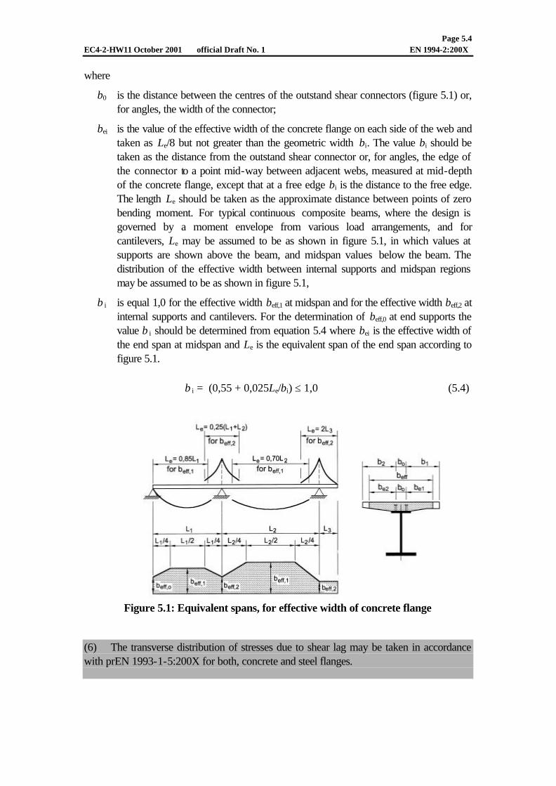
where
b0 is the distance between the centres of the outstand shear connectors (figure 5.1) or, for angles, the width of the connector;
bei is the value of the effective width of the concrete flange on each side of the web and taken as Le/8 but not greater than the geometric width bi. The value bi should be taken as the distance from the outstand shear connector or, for angles, the edge of the connector to a point mid-way between adjacent webs, measured at mid-depth of the concrete flange, except that at a free edge bi is the distance to the free edge. The length Le should be taken as the approximate distance between points of zero bending moment. For typical continuous composite beams, where the design is governed by a moment envelope from various load arrangements, and for cantilevers, Le may be assumed to be as shown in figure 5.1, in which values at supports are shown above the beam, and midspan values below the beam. The distribution of the effective width between internal supports and midspan regions may be assumed to be as shown in figure 5.1,
β i is equal 1,0 for the effective width beff,1 at midspan and for the effective width beff,2 at internal supports and cantilevers. For the determination of beff,0 at end supports the value β i should be determined from equation 5.4 where bei is the effective width of the end span at midspan and Le is the equivalent span of the end span according to figure 5.1.
β i = (0,55 + 0,025Le/bi) ≤ 1,0 (5.4)
Figure 5.1: Equivalent spans, for effective width of concrete flange
(6) The transverse distribution of stresses due to shear lag may be taken in accordance with prEN 1993-1-5:200X for both, concrete and steel flanges.

Page 5.5 EC4-2-HW11 October 2001 official Draft No. 1 EN 1994-2:200X
(7) For cross-sections with bending moments resulting from the main-girder system and from a local system (for example in composite trusses with direct actions on the chord between nodes) the relevant effective widths for the main girder system and the local system should be used for the relevant bending moments.
(8) The effective flange width for the dispersion of concentrated forces in longitudinal direction of the composite member should be determined for concrete elements in accordance with clause 5.3.2.1 of prEN 1992-1-1:2001 and for structural steel elements in accordance with prEN 1993-1-5:20XX. 5.4.2 Linear elastic analysis
5.4.2.1 General
(1)P Linear elastic analysis shall be based on the assumption that the stress-strain relationships for the materials are linear, whatever the stress level. (2) Allowance should be made for the effects of cracking of concrete, creep and shrinkage of concrete, sequence of construction and prestressing. 5.4.2.2 Stiffness assumptions
(1) Unless a more precise method is used, the elastic section properties of a composite cross-section with concrete in compression should be expressed as those of an equivalent steel cross-section by dividing the contribution of the concrete component by the relevant modular ratio according to 5.4.2.3(2). For cross-sections of a composite section with concrete in tension this concrete should be ignored. The uncracked and cracked flexural stiffness of a composite cross-section are defined as EaI1 and EaI2, respectively, where:
I1 is the second moment of area of the effective equivalent steel section calculated assuming that concrete in tension is uncracked
I2 is the second moment of area of the effective equivalent steel section calculated neglecting concrete in tension but including reinforcement.
(2) For composite columns, flexural stiffness including allowance for cracking of concrete should be determined in accordance with 6.7.3.4.
(3)The torsional stiffness of box girders should be calculated for a transformed cross section in which the slab thickness is reduced by the modular ratio n0G=Ga/Gc where Ga and Gc are the elastic shear moduli of structural steel and concrete respectively. The effects of creep may be taken into account in accordance with 5.4.2.3. The reduced thickness may be assumed to be located in the centre of the slab. In areas where the concrete slab is assumed to be cracked due to bending and where membrane shear stresses are so large that shear reinforcement is required, the calculation should be performed considering a slab thickness reduced to one half, unless the effect of cracking is considered in a more precise way.

Page 5.6 EC4-2-HW11 October 2001 official Draft No. 1 EN 1994-2:200X
5.4.2.3 Creep and Shrinkage
(1)P Appropriate allowance shall be made for the effects of creep and shrinkage of concrete.
(2) Unless a more precise method is used, the effects of creep may be taken into account by using modular ratios nL for the concrete, except for members with both flanges composite. The modular ratios depending on the type of loading (subscript L) are given by:
( )t0L 1 ϕψ+= nn (5.3)
where
n0 = Ea / Ecm is the modular ratio for short term loading, Ea is the modulus of elasticity for structural steel and Ecm is the secant modulus of elasticity of the concrete for short term loading according to table 3.1 or table 10.2 of prEN 1992-1:2001,
ϕt is the creep coefficient ϕ(t,t0) according to clause 3.1.3 or clause 10.3.1.3 of prEN 1992-1:2001 depending on the age (t) of concrete at the moment considered and the age (t0 ) at loading. For permanent loads on composite structures cast in several stages one mean value t0 may be used for the determination of the creep coefficient ϕ(t,t0), This assumption may also be used for prestressing by imposed deformations, if the age of all of the concrete in the relevant spans at the time of prestressing is more than 14 days.
For shrinkage, the age at loading should be assumed to be one day. Where prefabricated slabs are used, the creep coefficient from the time when the composite section becomes effective may be used.
ΨL is the creep multiplier depending on the type of loading, which be taken as 1,1 for permanent loads, 0,55 for primary and secondary effects of shrinkage and 1,5 for prestressing by imposed deformations.
(3) Where the bending moment distribution at the time t0 is significantly changed by creep, for example in continuous beams of mixed structures with both composite and non composite spans, the time dependent secondary effects due to creep should be considered except in global analysis for the ultimate limit state for members where all cross-sections are in Class 1 or 2. For the time dependent secondary effects the modular ratio may be determined with a creep multiplier ψL=0,55.
(4) Appropriate account should be taken of the secondary bending moments caused by shrinkage of the concrete slab. The effects of shrinkage of concrete may be neglected in verifications for ultimate limit states for composite structures, except in analysis with members having cross-sections in Class 3 or 4.
(5) In regions where the concrete slab is assumed to be cracked, the primary effects due to shrinkage may be neglected in the calculation of secondary effects.
(6) In composite columns, account should be taken of the effects of creep in accordance with 6.7.3.4.

Page 5.7 EC4-2-HW11 October 2001 official Draft No. 1 EN 1994-2:200X
(7) For double composite action with both flanges uncracked (e.g. in case of prestressing) the effects of creep and shrinkage should be determined by more accurate methods.
(8) Where prefabricated slabs are used or when prestressing of the concrete slab is carried out before the shear connection has become effective, the creep coefficient and the shrinkage values from the time where the composite section becomes effective should be used. 5.4.2.4 Effects of cracking of concrete
(1)P Appropriate allowance shall be made for the effects of cracking of concrete. (2) Allowance for the effects of cracking should be made by direct calculation as provided in this clause or in accordance with 5.4.3.
(3) The following method may be used for the determination of the effects of cracking. First the internal forces and moments for the characteristic combination including long term effects should be calculated using the flexural stiffness EaI1 of the uncracked sections. In regions where the extreme fibre tensile stress in the concrete slab due to the envelope of global effects exceeds the strength 2,0 fctm according to clause 3.1 of prEN1992-1:2001 the stiffness should be reduced to EaI2 according to 5.4.2.2(1). This distribution of stiffness may be used for ultimate limit states, and for serviceability limit states. A new distribution of internal forces and moments, and deformation if appropriate, is then determined by re-analysing the beam.
(4) For continuous beams with the concrete slab above the steel beam and not prestressed, including beams in frames which resist horizontal forces by bracing, simplified methods in accordance with (4) may be used.
(5) Where all the ratios of the length of adjacent continuous spans (shorter/longer) between supports are at least 0.6, the effect of cracking may be taken into account by using the flexural stiffness EaI2 according to 5.4.2.2(1) over 15% of the span on each side of each internal support, and as the uncracked values EaI1 elsewhere.
(6) The effect of cracking of concrete on the flexural stiffness of composite columns should be determined in accordance with 6.7.
(7) Unless a more precise method is used, in multiple beam decks where transverse members are subjected to bending only, it may be assumed that the transverse members are uncracked throughout 5.4.2.5 Stages and sequence of construction
(1)P Appropriate analysis shall be made to cover the effects of staged construction including where necessary separate effects of actions applied to structural steel and to wholly or partially composite members.

Page 5.8 EC4-2-HW11 October 2001 official Draft No. 1 EN 1994-2:200X
(2) The effect of sequence of construction may be neglected in analysis for ultimate limit states other than fatigue for composite members where all cross sections are in Class 1 or 2. 5.4.2.6 Temperature effects
(1)P Account shall be taken of effects due to temperature according to clause xxx of prEN 1991-1-5:20XX, where relevant.
(2) Temperature effects may normally be neglected in analysis for the ultimate limit states other than fatigue for composite members where all cross sections are in Class 1 or Class 2.
(3) If during concreting and hardening of concrete the temperature in the steel top flange due to extreme climatic conditions is very low additional differential temperature should be considered. 5.4.2.7 Prestressing by controlled imposed deformations
(1)P Where prestressing by controlled imposed deformations (e.g. jacking of supports) is provided, possible deviations from the assumed values of the imposed deformation and stiffness shall be considered for analysis of ultimate and serviceability limit states. (2) Unless a more accurate method is used, the characteristic values of indirect actions due to imposed deformations may be calculated with the characteristic or nominal values of properties of material and of imposed deformation, if the imposed deformations are controlled. 5.4.2.8 Prestressing by tendons
(1) Internal forces and moments due to prestressing by bonded tendons should be determined in accordance with XXX of prEN 1992-2:200X taking into account effects of creep and shrinkage of concrete and cracking of concrete where relevant.
(2) In global analysis, forces in unbonded tendons should be treated as external forces. For the determination of forces in permanently unbonded tendons, deformations of the whole structure should be taken into account.
5.4.2.9 Tension members in composite bridges
(1) In this clause the term composite system refers to structures in which shear connection applies global tensile forces to a reinforced or prestressed concrete or composite member. Typical examples are bowstring arches and trusses where the concrete or composite member acts as a tension chord in the main system.
(2) Composite tension members are members such as diagonals or chords in tension in trusses or ties in bowstring arches, consisting of structural steel, concrete and reinforcement with shear connection in accordance with 6.6.
(3)P For the determination of the forces of a concrete tension member and the sectional forces of the reinforced concrete element of a composite tension member, the effects of

Page 5.9 EC4-2-HW11 October 2001 official Draft No. 1 EN 1994-2:200X
cracking of concrete and tension stiffening of concrete shall be considered for the global analyses for ultimate and serviceability limit states and for the limit state of fatigue.
(4) Unless more accurate methods are used for concrete and composite tension members the effects of tension stiffening of concrete should be taken into account according to Annex XX of pr EN 1992-1:2001 using the mean value of tensile strength fctm according to table 3.1 of pr EN 1992-1:2001. In the verifications for ultimate limit states the effects of scattering of tensile strength of concrete should be taken into account by increasing the normal forces by 30% . Simplified methods are given in (6) and (7) below.
(5) For the calculation of the internal forces of a cracked concrete tension member the effects of shrinkage of concrete between cracks should be taken into account. Unless a more precise method is used the shrinkage strains valid for the uncracked concrete member according to 3.1.3 of prEN 1991-1: 2001should be used.
(6) For tension members the effects of tension stiffening of concrete may be neglected, if in the global analysis the internal forces of concrete tension members and the sectional forces of the reinforced concrete element of composite tensions members are determined with the uncracked stiffness. The internal forces of the structural steel member should be determined with the cracked stiffness (neglecting concrete in tension and effects of tension stiffening) .
(7) As an alternative to (6) internal forces in bowstring arches with a concrete tension member may be determined as follows: - determination of the internal forces of the steel structure with an effective
longitudinal stiffness (EA)eff of the cracked concrete tension member according to equation (5.4).
)1(/35,01)(
so
sseff ρ+−
=n
AEAE (5.4)
where no is the modular ratio for short term loading according to 5.4.2.3(2), As is the longitudinal reinforcement of the concrete tension member within the effective width and ρs is the reinforcement ratio ρs=As/Ac determined with the effective cross-section area Ac of the concrete tension member.
- the normal forces of the concrete tension member Nct,serv for the serviceability limit state and Nct,ult for the ultimate limit state are given by
)1(15,1 s0eff,ctc.serv,ct ρ+= nfAN (5.5)
)1(45,1 s0eff,ctc.ult,ct ρ+= nfAN (5.6)
where the symbols are defined above and fct,eff is the effective tensile strength of concrete. Unless verified by more accurate methods, the effective tensile strength may be assumed as fct,eff = 0,7 fctm where the concrete tension member is simultaneously acting as a deck and is subjected to combined global and local effects.
Page 5.10 EC4-2-HW11 October 2001 official Draft No. 1 EN 1994-2:200X
5.4.2.10 Composite plates in bridges
(1) This clause applies for composite plates consisting of a nominally flat plate of structural steel connected to a site cast concrete slab by headed studs, acting as a top flange in a bridge deck and subjected to transverse loads as well as in-plane forces or as a bottom flange in a box girder. Double skin plates or other types of connectors are not covered.
(2) For the analysis of local action effects it may be assumed that the concrete and the steel plate act compositely without slip.
(3) For the analysis of local effects caused by transverse loads the slab may be assumed elastic and uncracked and acting as one or two-way slab.
(4) When determining the effective width for global action effects according to 5.4.1.2, b0 should be taken as equal to the larger of 10 tf and 200 mm,where tf is the thickness of the plate.
5.4.2.10 Filler beam decks for bridges
(1) Internal forces and moments should be determined by uncracked elastic analysis. Where the detailing is in accordance with 6.3, in longitudinal bending the effects of slip between the concrete and the steel beams and effects of shear lag may be neglected. (2)P Where the distribution of loads applied after hardening of concrete is not uniform in the direction transverse to the span of the filler beams, the analysis shall take account of any difference between the deformation of adjacent filler beams, unless it is verified that sufficient accuracy is obtained by a simplified analysis assuming rigid cross-sections.
(3) Account may be taken of these deformations by using one of the following methods of analysis:
- modelling by an orthotropic continuum by smearing of the steel beams,
- considering the concrete as discontinuous so as to have a plane grid with members having flexural and torsional stiffness,
- general methods according to 5.4.3.
The torsional stiffness of the steel section may be neglected and the nominal value of Poission’s ratio, if needed for calculation may be assumed to be in all directions with zero for ultimate limit states and with 0.2 for serviceability limit states. In transverse bending, the presence of the steel beam may be ignored.
(4) Effects of creep on deformations may be taken into account according to 5.4.2.3. The effects of shrinkage of concrete may be neglected.
(5) the contribution of formwork supported from the steel beams, which becomes part of the permanent construction should be neglected.

Page 5.11 EC4-2-HW11 October 2001 official Draft No. 1 EN 1994-2:200X
(6) Hogging bending moments of continuous filler beams with Class1 cross-sections at internal supports may be redistributed for ultimate limit states other than fatigue by amounts not exceeding 15% to take into account inelastic behaviour of materials. For each load case the internal forces and moments after redistribution should be in equilibrium with the loads.
(7) For the determination of deflections and precamber for the serviceability limit state the effective flexural stiffness of filler beams decks may be taken as
)(5,0 2a1aeffa IEIEIE += (5.3)
where I1 and I2 are the uncracked and the cracked values of second moment of area of the composite cross-section subjected to sagging bending as defined in 5.4.2.2(1). The second moment of area I2 should be determined with the effective cross-section of structural steel, reinforcement and concrete in compression. The area of concrete in compression may be determined from the plastic stress distribution.
(8) The influences of differences and gradients of temperature may be ignored, except for the determination of deflections of non-ballasted railway bridges.
5.4.3 Non linear global analysis
(1) Non-linear analysis may be used for ultimate limit states other than fatigue, provided that equilibrium and compatibility are satisfied and an adequate non linear behaviour for materials according to (2) is assumed. The analysis can be first or second order.
(2) In general, the following effects should be considered:
- non linear behaviour caused by yielding of steel - non linear effects caused by concrete in compression including creep
- shrinkage of concrete
- non-linear behaviour caused by cracking of concrete including effects of tension stiffening
- the load-slip behaviour of shear connection
- behaviour of supports and joints
- shear lag effects
- effects caused by imperfections and buckling
- sequence of construction
- effects of torsional and distorsional warping
(3)P Regarding structural safety, paragraph 5.7(7) of prEN 1991-1:2001 and paragraph 6.3.2(4) of prEN 1990:2001 shall be considered. 5.4.4 Linear elastic analysis with limited redistribution for allowing cracking in
bridges (1) For continuous beams, including longitudinal beams in multiple–beam decks with the concrete slab above the steel beam, the method according to (2) for allowing cracking of

Page 5.12 EC4-2-HW11 October 2001 official Draft No. 1 EN 1994-2:200X
concrete may be used, where the sensitivity of the results of global analysis to the extent of cracking of concrete is low. The method applies for ultimate and serviceability limit states except for the ultimate limit states of fatigue for Categories A,B and C according to XXXX of prEN1992-2 no redistribution is allowed
(1) Hogging bending moments in the composite member at internal supports calculated by uncracked analysis and assumed to act on the composite member may be reduced by amounts not exceeding 10%. For each load case the internal forces and moments after redistribution should be in equilibrium with the loads. Drafting Note: It must be clarified whether this is applicable for all span ratios 5.5 Classification of cross-sections
5.5.1 General
(1)P The classification system defined in clause 5.5.2 of EN 1993-1-1:20xx applies to cross-sections of composite beams.
(2) A composite section should be classified according to the least favourable class of its steel elements in compression. The class of a composite section normally depends on the sign of the bending moment at that section.
(3) A steel compression element restrained by attaching it to a reinforced concrete element may be placed in a more favourable class, provided that the resulting improvement in performance has been established.
(4) For classification, the plastic stress distribution should be used with design values of strengths of materials; except at the boundary between Classes 3 and 4, where the elastic stress distribution should be used taking into account sequence of construction and the effects of creep and shrinkage. In hogging bending concrete in tension should be neglected. The distribution of the stresses should be determined for the gross cross-section of the steel web and the effective flanges.
(5)P For cross-sections in Class 1 and 2 with bars in tension, reinforcement should have a ductility Class B or C, see prEN 1992-1:200x table 3.5. Additionally a minimum area of reinforcement As within the effective width of the concrete flange is required to satisfy the following condition:
As ≥ ρs ⋅ Ac (5.7)
where Ac is the effective area of the concrete flange, and
cskctmys )/()235/( kfffδ=ρ (5.8)
fy is the nominal value of the yield strength of the structural steel in N/mm2,
fsk is the characteristic yield strength of the reinforcement,

Page 5.13 EC4-2-HW11 October 2001 official Draft No. 1 EN 1994-2:200X
fctm is the mean tensile strength of the concrete,
kc is a coefficient given in 7.3.2, and
δ is equal to 1,0 and 1,1 for Class 2 and Class 1 cross-sections, respectively.
(6) Welded mesh should not be included in the effective section unless it has been shown to have sufficient ductility, when built into a concrete slab, to ensure that it will not fracture. (7) In global analysis for stages in construction, account should be taken of the class of the steel section at the stage considered. 5.5.2 Classification of sections of filler beam decks for bridges (1) A steel outstand flange of a composite section should be classified in accordance with table 5.4 .
(2) A web in Class3 that is encased in concrete may be represented by an effective web of the same cross-section in Class 2.
Stress distribution (compression positive)
Class Type Limit
1 c/t ≤ 9ε 2 c/t ≤ 14ε 3
Rolled or welded
c/t ≤ 20ε

JB 125 DRAFT EN 1994-2 : 200X, 11 June 2001
1
Notes: This is from paper JB 115, with the changes agreed by PT2 in Athens. Some new provisions are underlined. Proposed changes to Part 1-1 will be included as and if PT1 accepts them. Corresponding clause numbers in ENV 1994-2 are given thus: [From 4.1.1(10)]. Drafting notes are given thus: [...] A comment in italic, thus [...], is a proposal or query for a change in prEN 1994-1-1. This draft is based on: • the Dec. 2000 draft of EN 1993-1-1, • the Jan. 2001 draft of EN 1992-1, • the May 2001 draft of EN 1993-1-5. 6 Ultimate limit states 6.1 Beams
6.1.1 Beams for bridges (1) Composite beams should be checked for: - resistance of cross-sections (see 6.2) - resistance to lateral-torsional buckling (see 6.4) - resistance to shear buckling and in-plane forces applied to webs (see 6.2.2 and 6.5) - resistance to longitudinal shear (see 6.6). (2) Where a deck slab spans longitudinally between composite cross beams, and is subjected to global action effects, there may also be local effects of the actions. Possible combination of these effects should be considered, where the extent of the local action is comparable with the effective width of the relevant concrete flange. This applies to verifications for ultimate limit states other than fatigue, and may apply to fatigue verifications for decks of composite bridges in category D or E according to clause .... of EN 1992-2:200X. [From 4.1.1(10)] [Omit, if this is sufficiently covered in EN 1994-2]
6.1.2 Effective width for verification of cross-sections (1) The effective width of the concrete flange for verification of cross-sections should be determined according to 5.4.1.2. (2) For simplification [insert ‘for buildings’?] a constant effective width may be assumed over the whole region in sagging bending of each span. This value may be taken as the value beff,1 at midspan. The same assumption applies over the whole region in hogging bending on both sides of an intermediate support. This value may be taken as the value beff,2 at the relevant support. 6.2 Resistances of cross-sections of beams
6.2.1 Bending resistance
6.2.1.1 General

JB 125 DRAFT EN 1994-2 : 200X, 11 June 2001
2
(1)P The design bending resistance may be determined by rigid plastic theory only where the effective composite cross-section is in Class 1 or Class 2 and where prestressing by bonded tendons is not used. [Proposed revision: ‘The plastic resistance moment according to 6.2.1.2 should not be used unless the effective cross-section is in Class 1 or 2. Also, it should not be used for members prestressed by bonded tendons’]
(2)P Non linear theory and elastic analysis for bending resistance may be applied to cross-sections of any class. It may be assumed that the composite cross-section remains plane if the shear connection and the transverse reinforcement are designed in accordance with clause 6.6, considering appropriate distributions of design longitudinal shear force. [Should be an AR]
(3)P The tensile strength of concrete shall be neglected.
(4) Account should be taken of fastener holes in steel elements in accordance with clause 8.2.6.1 of prEN 1993-1-1:200X. [Delete]
(5) Small holes in steel through which reinforcing bars pass should be treated as holes for fasteners. [Delete] (6) Where the steel element of a composite member is curved in plan, the effects of the curvature should be taken into account. [Should be in Part 1-1. If not, move to 6.2.1.3 of Part 2] 6.2.1.2 Plastic resistance moment of a composite cross-section
(1)P The following assumptions shall be made in the calculation of Mpl,Rd :
(a) there is full interaction between structural steel, reinforcement, and concrete;
(b) the effective area of the structural steel member is stressed to its design yield strength fyd in tension or compression;
(c) the effective areas of longitudinal reinforcement in tension and in compression are stressed to their design yield strength fsd in tension or compression. Alternatively, reinforcement in compression in a concrete slab may be neglected;
(d) the effective area of concrete in compression resists a stress of 0,85fcd, constant over the whole depth between the plastic neutral axis and the most compressed fibre of the concrete.
Typical plastic stress distributions are shown in Figure 6.2. [Para (1) should be an AR]
(2) For composite cross-sections with structural steel grade S420 or S460, where the distance xpl between the plastic neutral axis and the extreme fibre of the concrete slab in compression exceeds 15% of the overall depth h of the member, the design resistance moment MRd should be taken as β Mpl,Rd where β is the reduction factor given in Figure 6.3. For values xpl / h greater than 0,4 the resistance to bending should be determined from 6.2.1.4 or 6.2.1.5.
(3) Where the design resistance moment in hogging bending is determined by plastic theory, the reinforcement should be provided in accordance with 5.5.1(5). [Delete ‘in hogging bending’, add ‘in tension’after ‘reinforcement’]
(4) [No para. needed for bridges. Delete para (5) in Part 1-1.]

JB 125 DRAFT EN 1994-2 : 200X, 11 June 2001
3
Figure 6.2 Examples of plastic stress distributions for a composite beam with solid slab
and full shear connection in sagging and hogging bending [Drafting note: Fig. Nos. in this combined code are not sequential. This should be accepted]
Figure 6.3 Reduction factor ββ for Mpl.Rd
(5) Any profiled steel sheeting in tension included within the effective area in accordance with 5.4.2.2(3) should be assumed to be stressed to its design yield strength apyp / γf . [should be
deleted] 6.2.1.3 Special rules for beams in bridges
(1) Where a composite beam is subjected to biaxial bending, combined bending and torsion, or combined global and local effects, account should be taken of 6.2.1(2) and (3) of EN 1993-1-1:20xx when determining the contribution of the steel element of a composite flange to the resistance.

JB 125 DRAFT EN 1994-2 : 200X, 11 June 2001
4
(2) For the determination of forces in permanently unbonded tendons, the deformations of the whole member should normally be taken into account. 6.2.1.4 Non-linear resistance to bending
(1)P The bending resistance of a composite cross-section may be determined by non linear theory, taking into account the stress-strain relationships of the materials. The shear connection shall be designed to provide full continuity of displacements at the interface between steel and concrete.
(2) It should be assumed that the composite cross-section remains plane and that the strain in bonded reinforcement, whether in tension or compression, is the same as the mean strain in the surrounding concrete.
(3) The stresses in the concrete in compression should be derived from the stress-strain curve given in clause 3.1.6 of prEN 1992-1:2001. [‘should be in accordance with 3.1.6 of…’ because 3.1.6 gives more than one stress-strain curve]
(4) The stresses in the reinforcement should be derived from the bi-linear diagrams given in clause 3.2.4 of prEN 1992-1:2001. [Ref. is to clause 3.2.3, not 3.2.4]
(5) The stresses in structural steel in compression or tension may be derived from the bi-linear diagram given in 5.4.2.3(4) of EN 1993-1-1:200X or from a more precise diagram including strain-hardening and should take account of the effects of the method of construction (e.g. propped or unpropped ).
Figure 6.6 Simplified relationship between MRd and Nc
[Drafting note: to change subscripts Sd into Ed on figure] [and in 6.2.1.4(6)]

JB 125 DRAFT EN 1994-2 : 200X, 11 June 2001
5
(6) For Class 1 and Class 2 composite cross-sections in sagging bending, the non-linear resistance to bending, MRd , may be determined as a function of the compression force in the concrete, Nc , using the simplified expressions (6.4) and (6.5), as shown in Figure 6.6.
el
cSd,aRd,elSd,aRd )(
NN
MMMM −+= for elc NN ≤ (6.4)
elf,c
elcRd,elRd,plRd,elRd )(
NN
NNMMMM
−−
−+= for f,ccel NNN ≤≤ (6.5)
where : Mel,Rd is the moment that causes a tensile stress fyd in the extreme bottom fibre of the steel section in accordance with 6.2.1.5; where unpropped construction is used, the sequence of construction should be taken into account;
Ma,Sd is the sagging moment acting in the steel section due to actions on the structural steelwork alone before the composite action becomes effective;
Nel is the compressive force in the concrete slab corresponding to moment Mel.Rd.
[Nel should be Nel,d . The definition of Mel,d should state that it is equal to Ma,Ed plus
whatever moment applied to the composite section is needed, for fyd in tension to be
reached.] (7) The stresses in prestressing steel should be derived from the design curves in 3.3.3 of EN 1992-1:200X. The design initial pre-strain in prestressing tendons should be taken into account when assessing the stresses in the tendons. [from 4.4.1.3(4)] 6.2.1.5 Elastic resistance to bending (1) Stresses should be calculated by elastic theory, using an effective cross-section in accordance with 6.1.2.
(2) In the calculation of the elastic resistance to bending based on the effective cross-section, the limiting stresses should be taken as:
- 0,85 fcd in concrete in compression; [coefficient 0.85 to be deleted]
- fyd
in structural steel in tension or compression; [this para. should take account of the effect of
lateral buckling on this stress limit]
- fsd
in reinforcement in tension or compression. Alternatively, reinforcement in compression in a
concrete slab may be neglected.
(3)P Stresses due to actions on the structural steelwork alone shall be added to stresses due to actions on the composite member.
(4) Unless a more precise method is used, the effect of creep should be taken into account by use of a modular ratio according to 5.4.2.3.

JB 125 DRAFT EN 1994-2 : 200X, 11 June 2001
6
(5) In sections with concrete in tension and assumed to be cracked the stresses due to primary (isostatic) effects of shrinkage may be neglected. [This should be in Part 1.1] (6) In compression flanges susceptible to lateral torsional buckling, the compressive stress in the steel flange should not exceed that given by 6.4. [Depending on what is in para. (2)] (7) For cross-sections in Class 4, the effective section of structural steel should be according to 4.5 of EN 1993-1-5:20XX. (8) In the calculation of the elastic resistance to bending based on the effective cross-section, the limiting stress should be taken as fp, 0.1 k/γs in prestressing tendons according to 3.3.3 of EN 1992-1:200X. The stress due to initial prestrain in prestressing tendons should be taken into account in accordance with ??? of EN 1992-2:200X. [from 4.4.1.4(3)P] 6.2.2 Resistance to vertical shear
6.2.2.1 Scope (1) Clause 6.2.2 applies to composite beams with a rolled or welded structural steel section with a solid web, which may be stiffened. In welded sections, the steel flanges are assumed to be plates of rectangular cross-section. 6.2.2.2 Plastic resistance to vertical shear
(1)P The resistance to vertical shear shall be taken as the resistance of the structural steel section, unless the value for a contribution from the reinforced concrete part of the beam has been established.
(2) The design plastic shear resistance Vpl,Rd of the structural steel section should be determined in accordance with clause 6.2.6 of EN 1993-1-1:200X. 6.2.2.3 Shear buckling resistance
(1) The shear buckling resistance Vb,Rd of an uncased steel web should be determined in accordance with clause 6.4.2 of EN 1993-1-1:200X.
(2) No account should be taken of a contribution from the concrete slab, unless a more precise method than the one of EN 1993-1-1:200X is used and unless the shear connection is designed for the relevant vertical force. [Paras (1) and (2) should refer instead to EN 1993-1-5] 6.2.2.4 Additional rules for bridges (1) When applying 5.2.3.5(1) of EN 1993-1-5 for a beam with one flange composite, the dimension of the non-composite flange may be used even if that is the larger steel flange. The axial normal force NEd in 5.2.3.5(2) of EN 1993-1-5 should be taken as the axial force acting on the composite section. [From 4.4.3(3)] 6.2.2.5 Bending and vertical shear

JB 125 DRAFT EN 1994-2 : 200X, 11 June 2001
7
(1) Where the vertical shear VEd exceeds half the shear resistance VRd given by Vpl,Rd in 6.2.2.2 or Vb,Rd in 6.2.2.3, whichever is the smaller, allowance should be made for its effect on the resistance moment.
(2) For cross-sections in Class 1 or 2, the influence of the vertical shear on the resistance to bending may be taken into account by a reduced design steel strength (1- wρ ) fyd in the shear
area given in Figure 6.8 where:
2RdSdw )1/2( −=ρ VV (6.14)
(3)P For cross-sections in Class 3 and 4, clause 2.2.3.1 of EN 1993-1-5:200X is applicable using the calculated stresses of the composite section. [2.2.3.1 is wrong. This should probably be an AR] (4) Paragraphs (1) and (2) of 6.2.1.2 also apply for the calculation of Mf,Rd in 5.2.5.1 of EN 1993-1-5. The resistance of the flanges should be taken as the total strength of the concrete and reinforcement, as applicable. For cross-sections where paragraph (2) applies, the same value of β should be used for the calculation of Mf,Rd as for Mpl,Rd. [From 4.4.1.2(5)]
(1- ρρw)fyd
Figure 6.8: Plastic stress distribution modified by the effect of vertical shear
6.3 Filler beam decks
6.3.1 Scope (1) Clause 6.3 is applicable to decks consisting of a concrete slab reinforced by longitudinal steel filler beams and by reinforcing steel. [From K.1(1)P] (2) A typical cross-section of a filler beam deck with non-participating permanent formwork is shown in figure 6.xx. No application rules are given for fully encased beams.

JB 125 DRAFT EN 1994-2 : 200X, 11 June 2001
8
Figure 6.xx : Typical cross-section of a filler beam deck (3) Spans may be simply supported or continuous. Supports may be skew or not. (4) Steel beams may be rolled sections, or welded sections with a constant cross-section. For welded sections, both the width of the flanges and the depth of the web should be within the ranges that are available for rolled H- or I- sections. (5) To be within the scope of 6.3, filler-beam decks should comply with all of the following conditions : - the steel beams are straight in horizontal projection ; - the skew θ of all the supports complies with : 0 ≤ θ ≤ 30° (the value θ = 0 corresponding to a non-skew deck) ; - the nominal depth h of the steel beams complies with : 0,21 m ≤ h ≤ 1,10 m ; - the spacing of webs of the steel beams does not exceed the lesser of h/3 + 0,60 m and 0,75 m, where h is the nominal depth of the steel beams in metres ; - the concrete cover c above the steel beams satisfies the conditions: c ≥ 70 mm, c ≤ 150 mm, c ≤ h/3; - the clear distance between the upper flanges of the steel beams is not less than 150 mm, so as to allow pouring and compaction of concrete; [from K.6(1)] - the soffit of the lower flange of the steel beams is not encased ; - a bottom layer of transverse reinforcement passes through the webs of the steel beams, and is anchored beyond the end steel beams, and at each end of each bar, so as to develop its yield strength in accordance with 8.4 of EN 1992-1:20xx; high bond bars in accordance with 3.2.2 of EN 1992-1:20xx are used; their diameter is not less than 16 mm and their spacing is not more than 300 mm ; - normal-density concrete is used. (6) Half-through bridges where the deck consists of a concrete slab reinforced by transverse
steel filler beams and by reinforcing steel are not within the scope of 6.3. NOTE: Provisions for decks of this type may be given in a National Annex. 6.3.2 General (1)P Filler beam decks shall be designed for the serviceability and ultimate limit states. Steel beams that incorporate welding shall be checked against fatigue. [Delete ‘that incorporate welding’ ?] (2) Composite cross-sections should be classified according to 5.5.2. [From K.4.1(1)] (3) Mechanical shear connection need not be provided. [From K.2(1)] 6.3.2 Bending moments

JB 125 DRAFT EN 1994-2 : 200X, 11 June 2001
9
(1) The design resistance of composite cross-sections to bending moments should be determined according to 6.2.1. [From K.4.2(1)] (2)P The design resistance of reinforced concrete sections to bending moments should be determined according to 6.1 of EN 1992-1:200X. [From K.4.2(2)] 6.3.3 Vertical shear (1) The resistance of composite cross-sections to vertical shear should be determined according to 6.2.2, unless the value of a contribution from the reinforced concrete part has been established and verified according to 6.2 of EN 1992-2:200X. [From K.4.3(1)] (2) The design resistance to vertical shear of reinforced concrete sections between filler beams shall be verified according to 6.2 of EN 1992-1: 200X. [From K.4.3(2)] 6.3.4 Strength and stability of steel beams during execution (1) Steel beams before the hardening of concrete should be verified according to EN 1993-1-1:200X and EN 1993-2:200X. [Impracticable to list all the relevant clauses] [From K.4.4] 6.4 Lateral-torsional buckling of composite beams
6.4.1 General
(1) A steel flange that is attached to a concrete or composite slab by shear connection in accordance with 6.6 may be assumed to be laterally stable, provided that the overall width of the slab is not less than the depth of the steel member. In addition, for isolated beams, the distance between lateral supports shall be less than 30 times the slab width. [PT1 asked to review influence of restraints at ends of the member]
(2) All other steel flanges in compression should be checked for lateral stability.
(3)P In checks for lateral stability of beams built unpropped, the bending moment at any composite cross-section in Class 1 or 2 shall be taken as the sum of the moment applied to the composite member and the moment applied to its structural steel component. (4) For uniform members with cross sections in Class 1 or 2 the method given in 6.4.2 may be used.
eel member]
(5) The methods of EN 1993-1-1:200X are applicable for cross sections in Class 3 and 4 on the basis of the cross-sectional forces of the composite section, or the cross-sectional forces of the steel section, and the properties of the steel section alone, taking into account effects of sequence of construction. The lateral and elastic torsional restraint at the level of the connection to the concrete slab may be taken into account for cross-sections in Class 3 similarly to specifications given in 6.4.2(4)-(7). [Proposal: add ‘or 4’ after ‘Class 3’; delete ‘(4)-(7)’] 6.4.2 Verification of lateral-torsional buckling of uniform composite beams with cross-sections in Class 1 and 2 [add: ‘and a laterally stable top flange’, to exclude half-through

JB 125 DRAFT EN 1994-2 : 200X, 11 June 2001
10
bridges ?] [Whole of 6.4.2 to be reviewed after decision by PT1 on having a 6.4.2 ‘for buildings’]
(1) The design buckling resistance moment of a laterally unrestrained uniform composite beam with Class 1 or 2 cross-sections should be taken as:
Mb,Rd = LTχ MRd (6.15)
where : χLT is the reduction factor for lateral-torsional buckling depending on the relative slenderness
LTλ ,and MRd is the design resistance moment under hogging bending. [Wrong for a half-through bridge] Values of the reduction factor LTχ may be obtained from clause 6.3.2.2 of prEN 1993-1-1:200X. (2) For cross-sections in Class 1 or 2, MRd should be determined according to 6.2.1.2 for a beam with full shear connection, or 6.2.1.3 for a beam with partial shear connection, or 6.2.1.4 for a beam whose bending resistance is based on non-linear theory, or 6.3.2 for a partially-encased beam.
Figure 6.12 Inverted-U frame ABCD resisting to lateral-torsional buckling (3) The relative slenderness LTλ may be calculated by :
LTλcr
Rk
M
M= (6.16)
where :
MRk is the resistance moment of the composite section using the characteristic material properties (that is the value of MRd when the factors sca ,, γγγ are taken as 1,0) ;
Mcr is the elastic critical moment of the composite section for lateral-torsional buckling. For a composite beam assumed continuous at one or both ends, Mcr should be determined at the internal support of the relevant span where the hogging bending moment is maximum, using specialist literature or numerical analysis. [Wrong for a half-through bridge]
(4) Where the same slab is also attached to one or more supporting steel members approximately parallel to the composite beam considered and the conditions 6.4.3(c), (e) and (f) are satisfied, the calculation of the elastic critical moment, Mcr , may be based on the "continuous inverted U-frame" model. As shown in Figure 6.12, this model takes into account the lateral displacement of the bottom
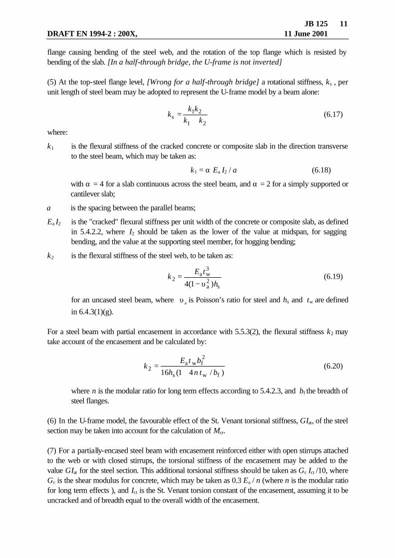
JB 125 DRAFT EN 1994-2 : 200X, 11 June 2001
11
flange causing bending of the steel web, and the rotation of the top flange which is resisted by bending of the slab. [In a half-through bridge, the U-frame is not inverted] (5) At the top-steel flange level, [Wrong for a half-through bridge] a rotational stiffness, ks , per unit length of steel beam may be adopted to represent the U-frame model by a beam alone:
21
21s kk
kkk
+= (6.17)
where:
k1 is the flexural stiffness of the cracked concrete or composite slab in the direction transverse to the steel beam, which may be taken as:
k1 = α Ea I2 / a (6.18)
with α = 4 for a slab continuous across the steel beam, and α = 2 for a simply supported or cantilever slab;
a is the spacing between the parallel beams;
Ea I2 is the "cracked" flexural stiffness per unit width of the concrete or composite slab, as defined in 5.4.2.2, where I2 should be taken as the lower of the value at midspan, for sagging bending, and the value at the supporting steel member, for hogging bending;
k2 is the flexural stiffness of the steel web, to be taken as:
s
2a
3wa
2)1(4 h
tEk
υ−= (6.19)
for an uncased steel beam, where aυ is Poisson’s ratio for steel and hs and tw are defined
in 6.4.3(1)(g). For a steel beam with partial encasement in accordance with 5.5.3(2), the flexural stiffness k2 may take account of the encasement and be calculated by:
)/41(16 fws
2fwa
2 btnh
btEk
+= (6.20)
where n is the modular ratio for long term effects according to 5.4.2.3, and bf the breadth of steel flanges.
(6) In the U-frame model, the favourable effect of the St. Venant torsional stiffness, GIat, of the steel section may be taken into account for the calculation of Mcr. (7) For a partially-encased steel beam with encasement reinforced either with open stirrups attached to the web or with closed stirrups, the torsional stiffness of the encasement may be added to the value GIat for the steel section. This additional torsional stiffness should be taken as Gc Ict /10, where Gc is the shear modulus for concrete, which may be taken as 0.3 Ea / n (where n is the modular ratio for long term effects ), and Ict is the St. Venant torsion constant of the encasement, assuming it to be uncracked and of breadth equal to the overall width of the encasement.

JB 125 DRAFT EN 1994-2 : 200X, 11 June 2001
12
6.4.3 Effects of transverse frames in bridges [Review when EC3-2 available] (1) The buckling resistance of a compressed flange that is laterally restrained by additional transverse frames between internal supports may be determined in accordance with ??? of EN1993-2. [from 4.6.3(1)] 6.5 Transverse forces on webs
6.5.1 General
(1) The rules given in clause 4.4 of EN 1993-1-5:200X to determine the design resistance of an unstiffened or stiffened web to transverse forces applied through a flange are applicable to the non-composite steel flange of a composite beam, and to the adjacent part of the web.
(2) If the transverse force acts in combination with bending and axial force, the resistance should be verified using clause 2.2.3.2 of EN 1993-1-5:200X.
(3) At an internal support of a beam designed using an effective web in Class 2 in accordance with 5.5.3(3), transverse stiffening should be provided unless it has been shown that the unstiffened web has sufficient resistance to crippling and buckling. 6.5.2 Flange-induced buckling of webs (1) The provisions in clause 4.4.6 of EN 1993-1-5:200X are applicable provided that area Afc is taken equal to the area of the non-composite steel flange or the transformed area of the composite steel flange, whichever is the smaller.

JB 126 Page 6.6.1 DRAFT EN 1994-2:200X, including Part 1-1, General, 11 June 2001
6.6 Shear connection [See the drafting notes at the start of Section 6 (paper JB 125)]
6.6.1 General
6.6.1.1 Basis of design (1) Clause 6.6 is applicable to composite beams and, as appropriate, to other types of composite member.
(2)P Shear connection and transverse reinforcement shall be provided to transmit the longitudinal shear force between the concrete and the structural steel element, ignoring the effect of natural bond between the two.
(3)P Ductile connectors are those with sufficient deformation capacity to justify the assumption of ideal plastic behaviour of the shear connection in the structure considered. [See Note on para. (12)]
(4) A connector may be taken as ductile if the characteristic slip capacity defined in 11.2.5(4) is at least 6mm.
(5)P Where two or more different types of shear connection are used within the same span of a beam, account shall be taken of any significant difference in their load-slip properties.
(6)P Shear connectors shall be capable of preventing separation of the concrete element from the steel element, except where separation is prevented by other means.
(7) To prevent uplift of the slab, shear connectors should be designed to resist a nominal ultimate tensile force, perpendicular to the plane of the steel flange, of at least 0,1 times the design ultimate shear resistance of the connectors. If necessary they should be supplemented by anchoring devices.
(8) Headed stud shear connectors in accordance with 6.6.5.7 may be assumed to provide sufficient resistance to uplift, unless the shear connection is subjected to direct tension.
(9)P Longitudinal shear failure and splitting of the concrete slab due to concentrated forces applied by the connectors shall be prevented.
(10) If the detailing of the shear connection is in accordance with the appropriate provisions of 6.6.5 and the transverse reinforcement is in accordance with 6.6.6, compliance with 6.6.1.1(9) may be assumed.
(11)P Where a method of interconnection, other than the shear connectors included in 6.6, is used to transfer shear between a steel element and a concrete element, the behaviour assumed in design shall be based on tests and supported by a conceptual model. The design of the composite member shall conform to the design of a similar member employing shear connectors included in 6, in so far as practicable. [This para. should be an AR. There are some provisions in EC4 that are not supported by conceptual models; e.g., longitudinal shear in filler- beam decks.] (12)P Shear connectors shall have sufficient deformation capacity to provide any inelastic redistribution of shear between connectors that is assumed in design. [from 6.1.2(1)P] [This is `General‘ and should be moved into para. (3)]
JB 126 Page 6.6.2 DRAFT EN 1994-2:200X, including Part 1-1, General, 11 June 2001
(13) Adjacent to cross frames and vertical web stiffeners, and for composite box girders, the effects should be considered of restraint by the shear connection of rotation of the slab about an axis parallel to the axis of the steel beam. [from 6.1.1(6)] NOTE: Further guidance may be given in a National Annex. 6.6.1.2 Ultimate limit states other than fatigue (1) For verifications for ultimate limit states, the size and spacing of shear connectors may be kept
constant over any length where the design longitudinal shear per unit length does not exceed the design shear resistance PRd by more than 10% Over every such length, the total design longitudinal shear force should not exceed N PRd, where N is the number of connectors within the length considered. [from 6.1.3(2) and 6.1.4(1)]
6.6.2 Longitudinal shear force in beams 6.6.2.1 Beams in which non-linear or elastic theory is used for resistances of one or more
cross-sections (1) If non-linear or elastic theory is applied to cross-sections, the longitudinal shear force should be determined in a manner consistent with 6.2.1.4 or 6.2.1.5 respectively. (2) For composite box girders, the longitudinal shear force on the connectors should include the effects of bending and torsion, and also of distortion according to ??? of EN 1993-2:200X, if this is not negligible. For box girders with a flange designed as a composite plate, see 9.9.4.[From 4.11(3) and (4)] (3) In members where cracking of concrete occurs, and account is taken in global analysis of the effects of tension stiffening, then in cracked regions, longitudinal shear per unit length may be determined taking account of tension stiffening. Elsewhere, and in uncracked members, the uncracked second moment of area I1 should be used. [From 6.2.1(3) and (4)] (4) Where concentrated longitudinal shear forces occur, account should be taken of the local effects of longitudinal slip; for example, as provided in 6.6.2.3 to 6.6.2.5. Otherwise, the effects of longitudinal slip may be neglected. [From 6.2.1(5)] (5) Where a sudden change of cross-section leads to an excessive local value for vSd, and in the absence of a more precise analysis, the distribution along the interface of the longitudinal shear force Vl caused by the change of cross-section may be assumed to be as given in 6.6.2.3, with ed taken as zero. [From 6.2.1(6)] 6.6.2.2 Beams in bridges with some cross-sections in Class 1 or 2 (1) In members with some cross-sections in Class 1 or 2, there may be lengths where the design bending moment MEd exceeds the bending resistance Mel,Rd, defined by Mel,Rd = Ma,Ed + k Mc,Ed ,

JB 126 Page 6.6.3 DRAFT EN 1994-2:200X, including Part 1-1, General, 11 June 2001
where Ma,Ed and Mc,Ed are the design bending moments applied to the steel element and the composite element, respectively, at each cross-section; and factor k (≤ 1) has the lowest value such that a stress limit given in 6.2.1.5 is reached at that cross-section. Within these inelastic lengths, shown as ABD in figure 6.13(a), account should be taken of the non-linear relationship between transverse shear and longitudinal shear. (2) The shear connection in length ABD may be verified as follows, for any distribution of bending moments MEd, where MEd = Ma,Ed + Mc,Ed. (a) Let B be the cross-section within ABD where the ratio of MEd to Mpl,Rd (as defined in 6.2.1.2) is a maximum. Let F denote longitudinal forces in the effective reinforced concrete flange, determined by elastic analysis of the composite section, with values: - Fe at section B when the bending moment is Mel,Rd, defined above; - Fe,A at section A when the bending moment is MEd,A; - Fe,D at section D when the bending moment is MEd,D.
Figure 6.13: Longitudinal shear in a beam in Class 1 or 2 [In Figure, Sd to be changed to Ed] (b) The numbers of shear connectors provided should be sufficient to resist forces FB - Fe,A within length AB and FB - Fe,D within length BD, where FB is the force given by line GH in figure 6.13(b) or, more accurately, is FB2 given by line JH, with Mpl,Rd, Fpl, Mel,Rd and Ma,Ed evaluated at section B. 6.6.2.3 Local effects of concentrated longitudinal shear force (1) Clause 6.6.2.3 is applicable to the determination of the distribution along an interface between steel and concrete of the design longitudinal shear force Vl caused by the isostatic effects of the application of a force Fd to the concrete or steel element by a bonded or unbonded tendon. The force Fd is the component of the relevant force in a direction parallel to the longitudinal axis of the comosite beam, applied after the shear connection has become effective. (2) The distribution of Vl caused by several forces F may be obtained by summation.

JB 126 Page 6.6.4 DRAFT EN 1994-2:200X, including Part 1-1, General, 11 June 2001
(3) In the absence of a more precise determination, the force Fd - Vl may be assumed to disperse into the concrete or steel element at an angle of spread 2β , where β = arc tan 2/3.
(4) The force Vl may be assumed to be distributed along a length Lv of shear connection as shown (for example) in figure 6.14(a), with a maximum shear force per unit length given by
vd,max = Vl / (ed + beff/2 ), where beff is the effective width for global analysis, given by 5.4.1.2, ed is either 2eh or 2ev, eh is the lateral distance from the point of application of force Fd to the relevant steel web, if it is applied to the slab, ev is the vertical distance from the point of application of force Fd to the plane of the shear connection concerned, if it is applied to the steel element. Values of the maximum axial forces shown in figure 6.14(b) are given by ∆N = vd,max beff /4. (5) Where the force Fd is applied over a length that is not negligible, that length may be added to ed. (6) Where stud shear connectors are used, a rectangular distribution of shear force per unit length may be assumed, so that vd,max = Vl / (ed + beff ). (7) Where shear connection is not present along the whole of the length Lv, (e.g., at a free end of a slab), the distribution of vd should be modified as appropriate.
Figure 6.14: Distribution of longitudinal shear force along the interface (8) If the force Fd is applied at a free end of the concrete or steel element, the distribution of the force Vl may be assumed to be half that shown in figure 6.14(a); i.e., extending along a length of shear connection Lv/2, with a maximum shear force per unit length given by

JB 126 Page 6.6.5 DRAFT EN 1994-2:200X, including Part 1-1, General, 11 June 2001
vd,max = 4 Vl / (2 ed + beff). 6.6.2.4 Temperature effects (1)P Longitudinal shear due to thermal actions in accordance with EN 1991-1-5 shall be considered, and taken into account where appropriate.
NOTE: the relevant effects are: -isostatic (primary) effects due to non-linear variation of temperature through the depth of the
composite member; -isostatic effects caused by a uniform change or linear variation of temperature, where the
coefficients of thermal expansion of the steel and concrete are significantly different; -hyperstatic (secondary) effects in continuous members due to restraint of the deformations
caused by the isostatic effects.
(2) Calculations for isostatic effects give a design longitudinal shear force, Vl, to be transferred across the interface between steel and concrete at each free end of the member considered. The distribution of this force may be assumed to be triangular, with a maximum shear force per unit length vd,max = 2 Vl / beff at the free end of the slab, where beff is the effective width for global analysis, given by 5.4.1.2. Where stud shear connectors are used, the distribution may alternatively be assumed to be uniform along a length beff adjacent to the free end of the slab. (3) The forces transferred by shear connectors may be assumed to disperse into the concrete slab at an angle of spread 2β , where β = arc tan 2/3. 6.6.2.5 Shrinkage modified by creep (1)P Where the effects of shrinkage of concrete adversely affect the maximum resultant forces on the shear connectors or the maximum resultant stresses in the concrete element, they shall be taken into account where appropriate. (2) Longitudinal shear caused by shrinkage of concrete may be neglected in continuous spans where all cross-sections of maximum bending moment (including those at internal supports) are in Class 1 or 2. It should not be neglected at free ends of cantilevers. (3) Where it is necessary to estimate the effects of shrinkage, they may be determined by a method similar to that given for temperature effects in 6.6.2.4, using a modular ratio that takes account of the reduction of shrinkage effects by creep of concrete in accordance with 5.4.2.3. (4) Where the isostatic (primary) effects of shrinkage are determined at intermediate stages of the construction of a concrete slab, the breadth beff in 6.6.2.4 should be determined for an equivalent

JB 126 Page 6.6.6 DRAFT EN 1994-2:200X, including Part 1-1, General, 11 June 2001
span equal to the continuous length of concrete slab where the shear connection is effective, within the span considered. 6.6.3 Headed stud connectors in solid slabs and concrete encasement
6.6.3.1 Design resistance (1) The design shear resistance of a headed stud automatically welded in accordance with EN ISO 14555:1998 “Welding – Arc stud welding of metallic materials” should be determined from :
í
2
uRd1
48.0
γ
π= dfP (6.28)
or : ( ) ícmck
2Rd /)(29.0 γα EfdP = (6.29)
whichever is smaller, where the partial safety factor γν should be taken as 1,25 for the ultimate limit state and :
d is the diameter of the shank of the stud;
fu is the specified ultimate tensile strength of the material of the stud but not greater than 500 N/mm2 ;
fck is the characteristic cylinder strength of the concrete at the age considered ;
Ecm is the mean value of the secant modulus of the concrete in accordance with clause 3.1.2 of EN 1992-1:200x for normal concrete and clause 10.3.1 for lightweight concrete ;
α = 0,2 [(h / d) + 1] for 3 ≤ h / d ≤ 4 ;
α = 1 for h / d > 4 ;
h is the overall height of the stud.
[Drafting note: The formulae may be too conservative for studs in lightweight concrete. A background document is to be prepared]
(2) The formulae in 6.6.3.1(1) should be verified by tests, see 11.2, before being used for: - studs of diameter greater than 25 mm, or- studs with weld collars which do not comply with the
requirements of EN ISO 13918:1998.
(3) Where the concrete density is not greater than 1750 kg/m3 or haunch dimensions do not satisfy 6.6.4.1 or 6.6.5.4, the design resistance should be determined using the characteristic resistance determined from push tests in accordance with 11.2. [This should be ‘Buildings’, because 6.6.4.1 is ‘Buildings’ and cannot be referred
to from a ‘General’ clause] 6.6.3.2 Influence of tension on shear resistance

JB 126 Page 6.6.7 DRAFT EN 1994-2:200X, including Part 1-1, General, 11 June 2001
(1) Where headed stud connectors are subjected to direct tensile force in addition to shear, the design tensile force per stud Ften should be calculated.
(2) If Ften ≤ 0,1PRd, where PRd is the design shear resistance defined in 6.6.3.1, the tensile force may be neglected.
(3) If Ften > 0,1PRd, the connection is not within the scope of this Part 1.1 of Eurocode 4. [Add: ‘NOTE: Guidance may be given in a National Annex’]. 6.6.4 Angle connectors (1) The design resistance of an angle connector welded to the steel beam as shown in figure 6.14A should be determined from PRd = 10 bh3/4 fck
2/3 / γν (6.39) where:
PRd is in Newtons b is the length of the angle in mm, h is the width of the upstanding leg of the angle in mm, fck is the characteristic strength of concrete in N/mm2.
The partial safety factor γν should be taken as 1.25 for the ultimate limit state. (2) In the design of the welds fastening the angle to the steel beam the eccentricity of the force should be taken as e = h / 4. (3) The welds should be designed in accordance with Section 3 of EN 1993-1-8:20xx for 1.2 PRd. (4) The reinforcement used to prevent uplift should be determined from: Ae fsk / γs ≥ 0.1 PRd (6.40) where:
Ae is the cross-sectional area of the bar, π Ø2 / 4 fsk is the characteristic yield strength of the reinforcement, γs is the partial safety factor for reinforcement in accordance with 2.2.5(1) of EN 1992-1:200x.
Figure 6.14A Angle connector

JB 126 Page 6.6.8 DRAFT EN 1994-2:200X, including Part 1-1, General, 11 June 2001
[No new figure No. is available] NOTE: Provisions for the use of friction grip bolts as shear connectors may be given in a
National Annex 6.6.5 Detailing of the shear connection
6.6.5.1 Resistance to separation
(1) The surface of a connector that resists separation forces (for example, the underside of the head of a stud) should extend not less than 30 mm clear above the bottom reinforcement.
6.6.5.2 Cover and compaction of concrete
(1)P The detailing of shear connectors shall be such that concrete can be adequately compacted around the base of the connector.
(2) If cover over the connector is required, it should be :
(a) not less than 20 mm, or
(b) as specified by Table 4.3 of EN 1992-1:200x for reinforcing steel, less 5 mm, whichever is greater. [table not Table; PNE rules, 4.4.4]
(3) If cover is not required the top of the connector may be flush with the upper surface of the concrete slab. (4) For bridges, cover over shear connectors should be according to (2).
6.6.5.3 Local reinforcement in the slab (1) Where the shear connection is adjacent to a longitudinal edge of a concrete slab, transverse reinforcement provided in accordance with 6.6.6 should be fully anchored in the concrete between the edge of the slab and the adjacent row of connectors, see 6.6.6.5.
(2)P At the end of a composite cantilever, sufficient local reinforcement shall be provided to transfer forces from the shear connectors to the longitudinal reinforcement.
6.6.5.4 Haunches other than formed by profiled steel sheeting
(1) Where a concrete haunch is used between the steel girder and the soffit of the concrete slab, the sides of the haunch should lie outside a line drawn at 45o from the outside edge of the connector, see Figure 6.15. [‘figure’ (PNE Rules, para. 4.4.4)] [‘beam’ not ‘girder’]
(2) The concrete cover from the side of the haunch to the connector should be not less than 50 mm.
(3) Transverse reinforcing bars sufficient to satisfy the requirements of 6.6.6 should be provided in the haunch at not less than 40 mm clear below the surface of the connector that resists uplift.

JB 126 Page 6.6.9 DRAFT EN 1994-2:200X, including Part 1-1, General, 11 June 2001
Figure 6.15: Dimensions of haunches
6.6.5.5 Spacing of connectors
(1)P Where it is assumed in design that the stability of either the steel or the concrete member is ensured by the connection between the two, the spacing of the shear connectors shall be sufficiently close for this assumption to be valid.
(2) Where a steel compression flange that would otherwise be in a lower class is assumed to be in Class 1 or Class 2 because of restraint from shear connectors, the centre-to-centre spacing of the shear connectors in the direction of compression should be not greater than the following limits: - where the slab is in contact over the full length (e.g. solid slab) : 22 t y/235 f
(a) where the slab is not in contact over the full length (e.g. slab with ribs transverse to the beam) 15 t y/235 f
where : [Replace (a) by -; add ‘:’ after ‘beam)’ ] t is the thickness of the flange ; fy is the nominal yield strength of the flange in N/mm2 units. In addition, the clear distance from the edge of a compression flange to the nearest line of shear connectors should be not greater than 9 t y/235 f .
(3) Connectors may be placed in groups, with the spacing of groups greater than that specified for individual connectors, provided that consideration is given in design to the non-uniform flow of longitudinal shear, to the greater possibility of slip and vertical separation between the slab and the steel member, and to buckling of the steel flange. (4) In a composite plate, the centre-to-centre spacing of the shear connectors in the direction of compression should not exceed 40 t √(235/fy). See also 9.9.4(4). [From 6.4.1.5(2)] (5) The maximum longitudinal centre-to-centre spacing of shear connectors should not exceed the lesser of four times the slab thickness and 800 mm. [From 6.4.1.5(3)] (6) Where 6.6.5.5(3) applies, consideration should be given in design to the local resistance of the slab to a concentrated force from the connectors. [From 6.4.1.5(4); or add to para. (3)]
6.6.5.6 Dimensions of the steel flange

JB 126 Page 6.6.10 DRAFT EN 1994-2:200X, including Part 1-1, General, 11 June 2001
(1)P The thickness of the steel plate or flange to which a connector is welded shall be sufficient to allow proper welding and proper transfer of load from the connector to the plate without local failure or excessive deformation. (2) The distance eD between the edge of a connector and the edge of the flange of the beam to which it is welded, see figure 6.15, should not be less than 25 mm. [From 6.4.1.6(2)] 6.6.5.7 Headed stud connectors (1) The overall height of a stud should be not less than 3d, where d is the diameter of the shank.
(2) The head should have a diameter of not less than 1,5d and a depth of not less than 0,4d
(3) The spacing of studs in the direction of the shear force should be not less than 5d; the spacing in the direction transverse to the shear force should be not less than 2,5d in solid slabs and 4d in other cases.
(4) Except when the studs are located directly over the web, the diameter of a welded stud should be not greater than 2.5 times the thickness of that part to which it is welded, unless test information is provided to establish the resistance of the stud as a shear connector. (5) For elements in tension and subjected to fatigue loading, the diameter of a welded stud should not exceed 1.5 times the thickness of the flange or plate to which it is welded, unless test information is provided to establish the fatigue resistance of the stud as a shear connector. This applies also to studs directly over a web. [from 6.4.2(4)] 6.6.5.8 Detailing - Angle connectors (1) The height h of the upstanding leg of an angle connector should not exceed 10 times its thickness nor 150 mm. [From 6.7.15(1)] (2) The length b of an angle connector should not exceed 300 mm unless the resistance is determined by testing in accordance with Section 11. [From 6.7.15 of Draft 2 of EN 1994-1-1] 6.6.6 Transverse reinforcement [To be re-written if PT1 adds ‘for buildings’to this heading]
6.6.6.1 Longitudinal shear in the slab (1)P Transverse reinforcement in the slab shall be designed for the ultimate limit state so that premature longitudinal shear failure or longitudinal splitting shall be prevented.
(2)P The design longitudinal shear per unit length for any potential surface of longitudinal shear failure within the slab vEd shall not exceed the design resistance to longitudinal shear vRd of the shear surface considered.

JB 126 Page 6.6.11 DRAFT EN 1994-2:200X, including Part 1-1, General, 11 June 2001
(3) The length of the shear surface b-b shown in figure 6.16 should be taken as equal to 2h plus the head diameter for a single row of stud shear connectors or staggered stud connectors, or as equal to 2h + st plus the head diameter for stud shear connectors arranged in pairs, where h is the height of the studs and st is the transverse spacing centre-to-centre of the studs.
(4) Where profiled steel sheeting is used transverse to the beam it is not necessary to consider shear surfaces of type b-b, provided that the design resistances of the studs are determined using the appropriate reduction factor kt as given in 6.6.4.2 . [This is for buildings, and so should be at the end of this clause]
Type
Ae
a - a ( Ab + At )
b - b 2 Ab
c - c 2 ( Ab + Abh)
d - d 2Abh
e - e At
f - f 2Ab
g - g ( Ab + At )
[Drafting note: to clarify arrangement of reinforcement in the diagram showing precast units]
Figure 6.16 Typical potential surfaces of shear failure (5) The design longitudinal shear per unit length of beam on a shear surface, vEd, should be determined in accordance with 6.6.2 and be consistent with the design of the shear connectors. Alternatively, the longitudinal shear force in the beam should be limited to the design resistance to

JB 126 Page 6.6.12 DRAFT EN 1994-2:200X, including Part 1-1, General, 11 June 2001
longitudinal shear and account shall be taken of this in determining the resistance moment.[Lines 1 and 2 are ‘General’. The second sentence should be ‘for Buildings’. (The word ‘consistent’ is unclear when the shear connection is governed by fatigue)] [A new second sentence is needed for bridges]
(6) In determining vEd account may be taken of the variation of longitudinal shear across the width of the concrete flange. (7) For bridges, (3) applies with st taken as the transverse distance centre-to-centre between the studs nearest to the two edges of the flange, or as the overall length of a row of angle connectors. [Based on 6.6.1(3)]
6.6.6.2 Design resistance to longitudinal shear (1)P The design resistance of the concrete flange (shear planes a-a illustrated in Figure 6.16) shall be determined in accordance with the Principle in clause 6.2.4 of prEN 1992-1:200x. Profiled steel sheeting with ribs transverse to the steel beam may be assumed to contribute to resistance to longitudinal shear, if it is continuous across the top flange of the steel beam or if it is welded to the steel beam by stud shear connectors. [The first sentence should be an AR, and read ‘…accordance with 6.2.4…’. The second sentence is not applicable to bridges, and should be an AR in a separate paragraph, later] [There is no normative reference to figure 6.16 and no definition of the symbols in it, especially Ae ] [6.2.4(1) of prEN 1992-1 says ‘may be calculated’. Why is this replaced by
[Only two of the eight pictures in Fig. 6.16 are relevant to bridges, so the Figure should be ‘for Buildings’]
(2) In the absence of a more accurate calculation the design resistance of any surface of potential shear failure in the flange or a haunch may be determined from clause 6.2.4(4) of prEN 1992-1:200x.
(3) Transverse reinforcement taken into account for resistance to longitudinal shear should be anchored in accordance with section 9 of prEN 1992-1:200x. (4) Where a combination of precast elements and insitu concrete is used, the resistance to longitudinal shear should be determined in accordance with clause 6.2.5 of prEN 1992-1:200x. (5) Any reinforcement provided to resist hogging transverse bending of an unhaunched slab may be assumed to be effective as bottom transverse reinforcement. [From 6.7.17.2(3) of Draft 2 of EN 1994-1-1] 6.6.6.3 Vacant 6.6.6.4 Vacant 6.6.6.5 Longitudinal splitting (1) To prevent longitudinal splitting of the concrete flange caused by the shear connectors, the following additional recommendations should be applied in all composite beams where the distance from the edge of the concrete flange to the centreline of the nearest row of shear connectors is less than 300 mm :

JB 126 Page 6.6.13 DRAFT EN 1994-2:200X, including Part 1-1, General, 11 June 2001
(a) transverse reinforcement should be supplied by U-bars passing around the shear connectors;
(b) where headed studs are used as shear connectors, the distance from the edge of the concrete flange to the centre of the nearest stud should not be less than 6d, where d is the nominal diameter of the stud, and the U-bars should be not less than 0,5d in diameter ;
(c) the U-bars should be placed as low as possible while still providing sufficient bottom cover. [NOTE: These conditions normally apply to edge beams but may also occur adjacent to large
openings.][NOTES do not have square brackets; see PNE Rules.] [ Move this clause to 6.6.6.3 to avoid unused clause Nos. in Part 2]

JB 127, Page 6.7 - DRAFT EN 1994-2:200X 30 July 2001
1
6.7 Composite columns and composite compression members [Drafting note. See the drafting notes at the start of Section 6, paper JB125. No ‘Bridges’ provisions are proposed for 6.7] 6.7.1 General
(1)P Section [Clause] 6.7 applies for the design of composite columns and composite compression members with concrete encased sections, see Figure 6.7-1a, partially encased sections, see Figures 6.7-1b and 6.7-1c, and concrete filled circular and rectangular tubes, see Figures 6.7-1d to 6.7-1f. The steel section can be rolled or welded and the steel section and the uncracked concrete section usually have the same centroid. [Last line not normative; what if
there are different centroids ?] [figure not Figure; PNE rules]
Fig. 6.7-1 Typical cross-sections of composite columns, notations (2)P This clause applies to composite columns and composite compression members with steel grades S235 to S460 inclusive and normal weight concrete of concrete strength classes C20/25 to C50/60.
(3) This clause applies for isolated composite columns and composite columns and composite compression members in framed structures where the other structural members are either composite or steel members.
(4) The steel contribution ratio δ should fulfil the condition : 9.02.0 ≤δ≤ (6.7-1) where the steel contribution ratio δ, defined in 6.7.3.3(1), is the ratio of the plastic resistance to compression of the structural steel to that of the composite section.
(5) Composite columns or compression members of any cross-section should be checked for : - resistance of the member in accordance with 6.7.2 or 6.7.3, - resistance to local buckling in accordance with (8) or (9) below,

JB 127, Page 6.7 - DRAFT EN 1994-2:200X 30 July 2001
2
- introduction of loads in accordance with 6.7.4.2, and - resistance to shear between steel and concrete elements in accordance with 6.7.4.3.
(6) Two methods of design are given :
- a general method in 6.7.2 whose scope includes members with non-symmetrical or non-uniform cross-sections over the column length, and
- a simplified method in 6.7.3 for members of double symmetrical and uniform cross-section over the member length.
(7)P For composite compression members subjected to bending moments and normal forces resulting from independent actions, the partial safety factor γF for those internal forces that lead to an increase of resistance shall be reduced to 80%. [Should be an AR; the 80% is empirical.]
(8)P The influence of local buckling of steel members on the resistance shall be considered in design.
(9) The effects of local buckling of steel members in composite compression members may be neglected for steel sections fully encased in accordance with 6.7.5.1(2), and for other types of cross-sections provided the maximum values of Table 6.7-1 are not exceeded where fyk is the characteristic value of the yield strength of structural steel. [table not Table, see PNE Rules]
Table 6.7-1 Maximum values (d/t), (h/t) and (b/tf) with fy,k in N/mm2
cross-section max (d/t), max (h/t) and max (b/t)
circular hollow steel sections
ky,
23590)(max
fd/t =
rectangular hollow steel sections
k,y
23552)(max
fh/t =
partially encased I-sections
k,yf
23544)(max
fb/t =
6.7.2 General method of design (1)P Design for structural stability shall take account of second order effects including residual stresses, geometrical imperfections, local instability, cracking of concrete, creep and shrinkage of
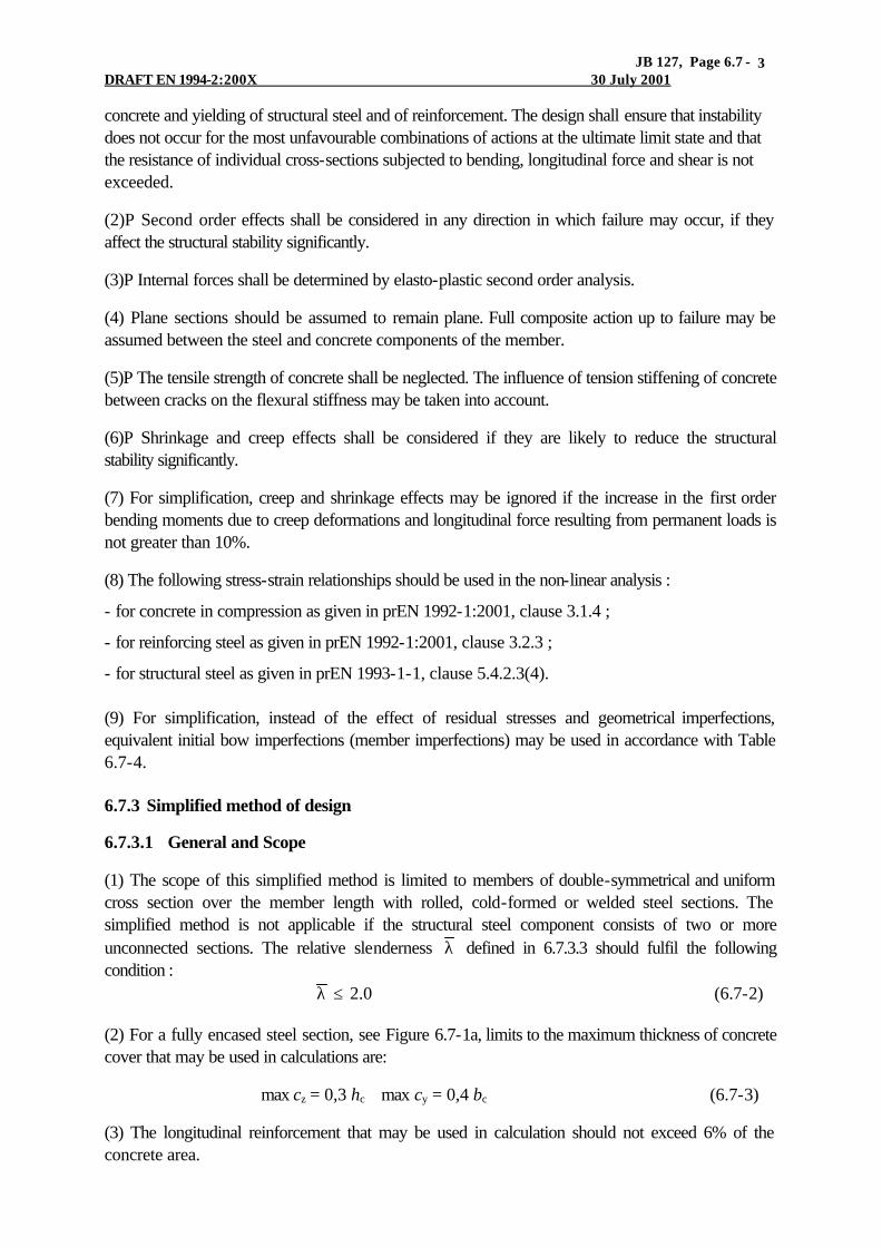
JB 127, Page 6.7 - DRAFT EN 1994-2:200X 30 July 2001
3
concrete and yielding of structural steel and of reinforcement. The design shall ensure that instability does not occur for the most unfavourable combinations of actions at the ultimate limit state and that the resistance of individual cross-sections subjected to bending, longitudinal force and shear is not exceeded.
(2)P Second order effects shall be considered in any direction in which failure may occur, if they affect the structural stability significantly.
(3)P Internal forces shall be determined by elasto-plastic second order analysis.
(4) Plane sections should be assumed to remain plane. Full composite action up to failure may be assumed between the steel and concrete components of the member.
(5)P The tensile strength of concrete shall be neglected. The influence of tension stiffening of concrete between cracks on the flexural stiffness may be taken into account.
(6)P Shrinkage and creep effects shall be considered if they are likely to reduce the structural stability significantly.
(7) For simplification, creep and shrinkage effects may be ignored if the increase in the first order bending moments due to creep deformations and longitudinal force resulting from permanent loads is not greater than 10%.
(8) The following stress-strain relationships should be used in the non-linear analysis :
- for concrete in compression as given in prEN 1992-1:2001, clause 3.1.4 ;
- for reinforcing steel as given in prEN 1992-1:2001, clause 3.2.3 ;
- for structural steel as given in prEN 1993-1-1, clause 5.4.2.3(4). (9) For simplification, instead of the effect of residual stresses and geometrical imperfections, equivalent initial bow imperfections (member imperfections) may be used in accordance with Table 6.7-4. 6.7.3 Simplified method of design
6.7.3.1 General and Scope
(1) The scope of this simplified method is limited to members of double-symmetrical and uniform cross section over the member length with rolled, cold-formed or welded steel sections. The simplified method is not applicable if the structural steel component consists of two or more unconnected sections. The relative slenderness λ defined in 6.7.3.3 should fulfil the following condition : 0.2≤λ (6.7-2)
(2) For a fully encased steel section, see Figure 6.7-1a, limits to the maximum thickness of concrete cover that may be used in calculations are:
max cz = 0,3 hc max cy = 0,4 bc (6.7-3)
(3) The longitudinal reinforcement that may be used in calculation should not exceed 6% of the concrete area.

JB 127, Page 6.7 - DRAFT EN 1994-2:200X 30 July 2001
4
(4) The ratio of member height hc to member width bc, see Figure 6.7-1a, should be within the limits 0,2 ≤ hc/bc ≤ 5.0. 6.7.3.2 Resistance of cross sections
(1) The plastic resistance to compression Npl,Rd of a composite cross-section should be calculated by adding the plastic resistance of its components :
sdscdcydaRd,pl 85,0 fAfAfAN ++= (6.7-4)
where for concrete encased and partially concrete encased steel sections the coefficient on the resistance of concrete is 0,85 and may be taken as 1.0 for concrete filled sections. [Alternative wording: ‘This applies for concrete encased and partially concrete encased steel sections. For concrete-filled sections the coefficient 0,85 may be replaced by 1.0’.]
(2) The resistance of cross-section to combined compression and bending and the corresponding interaction curve should be calculated assuming rectangular stress blocks as shown in Figure 6.7-2, taking account of the design shear force VSd in accordance with (3). The tensile strength of the concrete should be neglected. [‘cross-sections in line 1]
Fig. 6.7-2 Interaction curve for combined compression and uniaxial bending
(3) The influence of transverse shear forces on the resistance to bending and normal force should be considered when determining the interaction curve, if the shear force Va,Ed of the steel section exceeds 50% of the design shear resistance Vpla,Rd of the steel section, see clause 6.2.2.2.
Where Va,Ed > 0.5 Vpla,Rd , the influence of the transverse shear on the resistance in combined bending and compression should be taken into account by a reduced design steel strength ρw⋅ fyd in the shear area Av in accordance with 6.2.2.5(2) and Figure 6.7-2. Alternatively a reduced thickness ρw⋅ tw of the web can be used for the determination of the interaction curve.
The shear force Va,E d of the structural steel section should not exceed the resistance to vertical shear of the steel section determined according to 6.2.2. The resistance to vertical shear Vc,Ed of the reinforced concrete part should be verified in accordance with [6.2 of] EN 1992-1:2001. For simplification the shear force may be assumed to act on the structural steel section alone. [The third paragraph, and perhaps the second, need paragraph numbers]

JB 127, Page 6.7 - DRAFT EN 1994-2:200X 30 July 2001
5
(4) Unless a more accurate analysis is used, the transverse vertical shear VEd may be distributed into Va,Ed acting on the structural steel and Vc,Ed acting on the reinforced concrete section by :
Rd,pl
Rd,plaSdSd,a M
MVV = (6.7-5)
Sd,aSdSd,c VVV −= (6.7-6)
where Mpla,Rd is the plastic resistance moment of the steel section and Mpl,Rd is the plastic resistance moment of the composite section.
(5) As a simplification, the interaction curve may be replaced by a polygonal diagram (the dashed line in Figure 6.7-3). Figure 6.7-3 shows as an example the plastic stress distribution of a fully encased cross section for the points A to D. Npm,Rd should be taken as 0,85 fcd Ac for concrete encased and partially concrete encased sections and as fcd Ac for concrete filled sections.
Fig. 6.7-3 Simplified interaction curve and corresponding stress distributions (6) For concrete filled tubes of circular cross section, account may be taken of increase in strength of concrete caused by confinement provided that the relative slenderness λ defined in 6.7.3.3 does not exceed 0,5 and e/d < 0,1, where e is the eccentricity of loading given by e=MSd/NSd and d is the external diameter of the column. The plastic resistance to compression may then be calculated from the following expression :
sdsck
yccdcydaaRd,pl 1 fA
f
f
d
tfAfAN +
η++η= (6.7-7)
where t is the wall thickness of the steel tube. For members in axial compression with e=0 the values ηa=ηao and ηc= ηco are given by the following expressions :
ηao = 0,25(3 + 2 λ ) (but ≤ 1,0) (6.7-8) ηco = 4,9 – 18,5 λ + 17 λ 2 (but ≥ 0) (6.7-9)

JB 127, Page 6.7 - DRAFT EN 1994-2:200X 30 July 2001
6
For members in combined compression and bending with 0< e/d ≤ 0,1, the values ηa and ηc should be determined from expressions (6.7-10) and (6.7-11), where ηao and ηco are given by the equations (6.7-8) and (6.7-9) :
ηa = ηao + (1- ηao)(10e/d) (6.7-10)
ηc = ηco(1 – 10e/d) (6.7-11) For e/d >0,1, ηa= 1,0 and ηc=0. 6.7.3.3 Effective flexural stiffness, steel contribution ratio and non-dimensional slenderness
(1) The steel contribution ratio δ [is] defined as : Rd,pl
yda
N
fA=δ (6.7-12)
where the design value for axial plastic resistance Npl,Rd is defined in 6.7.3.2 (1).
(2) The relative slenderness λ for the plane of bending considered is given by :
cr
Rk,pl
N
N=λ (6.7-13)
where :
Npl,Rk is the characteristic value of plastic resistance to compression given by equation (6.7-4) if, instead of the design strengths, the characteristic values are used, and
Ncr is the elastic critical load, calculated with the effective flexural stiffness (EI)eff,λ determined in accordance with (3) and (4).
(3) For the determination of the relative slenderness λ and the elastic critical load Ncr, the characteristic value of the effective flexural stiffness (EI)eff,λ of a cross section of a composite column should be calculated from
ccmessaa,eff)( IEKIEIEIE ++=λ (6.7-14)
where Ia, Is and Ic are the second moments of area for the bending plane being considered, for the structural steel, reinforcement and the uncracked concrete section, respectively. Ea and Es are the elastic moduli for structural steel and reinforcement and Ecm is the modulus of elasticity of concrete given by Table 3.1 of prEN 1992-1:2001. The factor Ke is a correction factor for cracking of concrete which may be taken as Ke=0.6.
(4) Account should be taken to the influence of long-term effects on the effective elastic flexural stiffness where 6.7.3.4(4) applies. The modulus of elasticity of concrete Ecm should be reduced to the value Ec in accordance with the following expression :
td,SSd,Gcmc )/(1
1ϕ+
=NN
EE (6.7-15)

JB 127, Page 6.7 - DRAFT EN 1994-2:200X 30 July 2001
7
where ϕ t is the creep coefficient according to 5.4.2.3(2), NEd is the maximum design normal force and NG,Ed is the part of this normal force that is permanent. For the determination of the creep coefficient in accordance with clause 3.1.3 of prEN 1992-1:200x, a relative humidity of 100% may be assumed for concrete filled hollow sections. 6.7.3.4 Methods of analysis and member imperfections
(1) Analysis should be based on linear elastic second order analysis.
(2) For the determination of the internal forces based on linear elastic second order analysis the design value of effective flexural stiffness (EI)eff,II should be determined from the following expression : )()( ccmII,essaaoII,eff IEKIEIEKIE ++= (6.7-16)
where Ke,II =0,5 and Ko=0,9. When long term effects should be taken into account, see (4) below, the modulus of elasticity Ecm should be reduced to a value Ec given by expression (6-7.15).
(3) Isolated non sway columns and compression members need not be checked for second order effects if 5.2.1(2) applies and the elastic critical load is determined from the flexural stiffness (EI)eff,II in accordance with (2). For members with end moments, second order effects need not to be considered if the relative slenderness λ does not exceed the following limiting value : [Refer to definitions of ‘isolated’ and ‘non sway’ in 5.8.1 of EN 1992-1 ? They have not been found in EN 1993-1-1. Is this correct for bridges ?]
)2(2.002
01crit M
M−=λ (6.7-17)
where M01 and M02 are the first order end moments, with 0102 MM ≥ .
[It is understood that para (3) will be deleted from Part 1-1.] (4) The influence of long term effects on the elastic flexural stiffness should be considered where the relative slenderness λ in the plane of bending being considered exceeds the values max λ given in Table 6.4 and e/d < 2, where e is the eccentricity of loading given by e=MEd/NSd and d is the overall depth of the composite cross-section in the plane of bending being considered. For comparison with the limits given in Table 6.7-2, max λ may be calculated without considering the influence of long-term effects on flexural stiffness.
Table 6.7-2: Maximum slenderness for neglect of long term effects
structure
max λ
braced non sway frames
sway frames and/or unbraced frames
concrete encased and partially concrete encased sections
0.8
0.5
circular and rectangular concrete filled hollow sections
0.8/(1-δ)
0.5/(1-δ)
[Refer to definitions of types of frame in EN 1992-1?]

JB 127, Page 6.7 - DRAFT EN 1994-2:200X 30 July 2001
8
(5) The influence of geometrical and structural imperfections may be taken into account by equivalent geometrical imperfections. System imperfections should be allowed for in accordance with 5.3.2. Member imperfections for composite columns are given in table 6.7-4, where L is the column length. (6) Second-order effects may be included indirectly by using a first-order analysis with appropriate amplification. Table 6.7-3 Factors ββ for the determination of moments to second order theory
Moment distribution moment factors β Comment
First-order bending moments from member imperfection or lateral load
β = 1,0
MEd is the maximum bending
moment within the column length ignoring second order effects
End moments
β = 0,66 + 044r but β ≥ 0.44
MEd and r⋅MEd are the end
moments from first-order global analysis
(7) Second-order effects in an isolated non-sway column may be allowed for by increasing the greatest first-order design bending moment MEd by a factor k given by
k = β / [1 - (NEd /Ncr )] ≥ 1,0 (6.7-18)
where Ncr is the critical load for the relevant axis and corresponding to the effective flexural stiffness given in 6.7.3.4(2), with the effective length l taken as the column length, and β is an equivalent moment factor given in table 6.7-3. In the absence of more accurate calculation the value of β should not be taken less than 1,0 for combined action of moments from member imperfection and end moments and/or moments from lateral load. [Queries for PT2 (which drafts of EN 1992-2 or 1993-2 may answer): (1) Many types of ‘frame’ occur in bridge sub-structures, involving different types of bearing. The compression members can be composite in trusses, and concrete-filled tubes find application in multi-level highway intersections. Do Sections 5 and 6 focus sufficiently on analyses and resistance of systems of this type ? Should provisions be given for isolated columns loaded at one or both ends through bearings with various degrees of freedom ? What bending moments should such a column be designed for if loaded ‘axially‘ through ‘pin joints’ at both ends ? (2) Inclined compression members are usually of steel. Are there any examples of inclined composite compression members ? Should EC4 refer to them at all ? ]
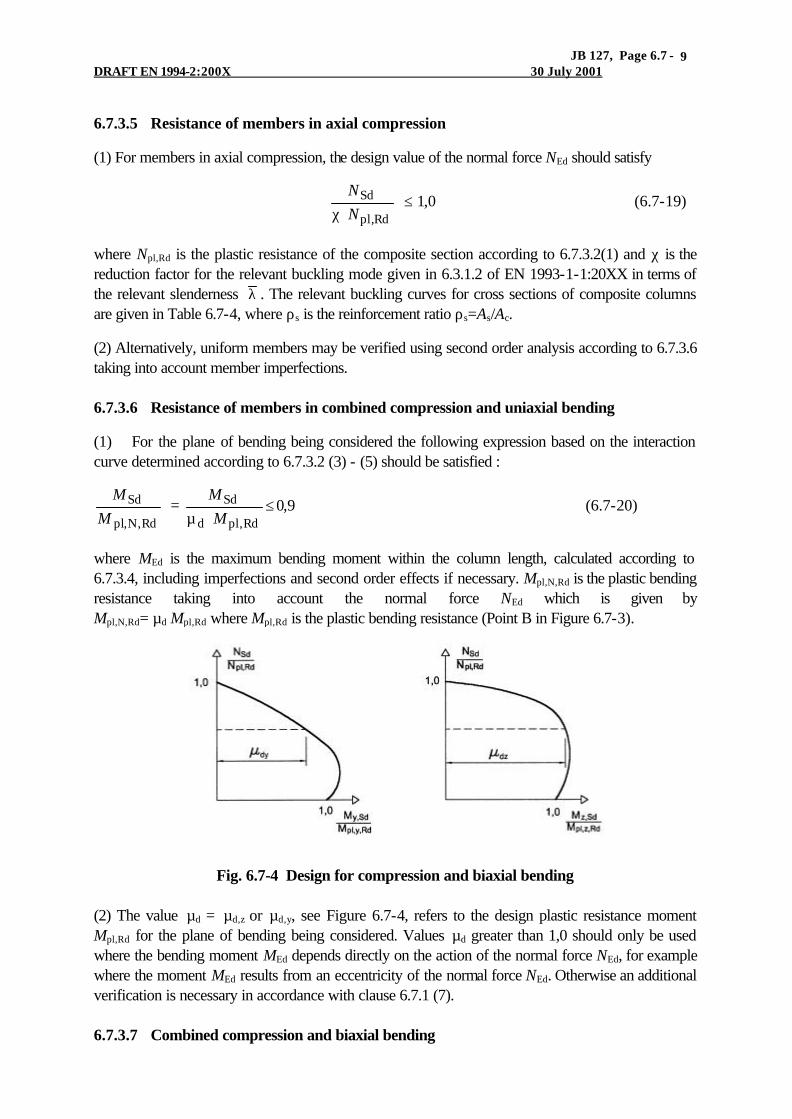
JB 127, Page 6.7 - DRAFT EN 1994-2:200X 30 July 2001
9
6.7.3.5 Resistance of members in axial compression
(1) For members in axial compression, the design value of the normal force NEd should satisfy
0,1Rd,pl
Sd ≤χ N
N (6.7-19)
where Npl,Rd is the plastic resistance of the composite section according to 6.7.3.2(1) and χ is the reduction factor for the relevant buckling mode given in 6.3.1.2 of EN 1993-1-1:20XX in terms of the relevant slenderness λ . The relevant buckling curves for cross sections of composite columns are given in Table 6.7-4, where ρs is the reinforcement ratio ρs=As/Ac.
(2) Alternatively, uniform members may be verified using second order analysis according to 6.7.3.6 taking into account member imperfections. 6.7.3.6 Resistance of members in combined compression and uniaxial bending
(1) For the plane of bending being considered the following expression based on the interaction curve determined according to 6.7.3.2 (3) - (5) should be satisfied :
9,0Rd,pld
Sd
Rd,N,pl
Sd ≤µ
=M
M
M
M (6.7-20)
where MEd is the maximum bending moment within the column length, calculated according to 6.7.3.4, including imperfections and second order effects if necessary. Mpl,N,Rd is the plastic bending resistance taking into account the normal force NEd which is given by Mpl,N,Rd= µd Mpl,Rd where Mpl,Rd is the plastic bending resistance (Point B in Figure 6.7-3).
Fig. 6.7-4 Design for compression and biaxial bending (2) The value µd = µd,z or µd,y, see Figure 6.7-4, refers to the design plastic resistance moment Mpl,Rd for the plane of bending being considered. Values µd greater than 1,0 should only be used where the bending moment MEd depends directly on the action of the normal force NEd, for example where the moment MEd results from an eccentricity of the normal force NEd. Otherwise an additional verification is necessary in accordance with clause 6.7.1 (7). 6.7.3.7 Combined compression and biaxial bending

JB 127, Page 6.7 - DRAFT EN 1994-2:200X 30 July 2001
10
(1) For composite columns and compression members with biaxial bending the values µdy and µdz in Figure 6.7-4 may be calculated according to 6.7.3.6 separately for each axis. Imperfections should be considered only in the plane in which failure is expected to occur. If it is not evident which plane is the more critical, checks should be made for both planes.
Table 6.7-4: Relevant buckling curves and member imperfections for composite columns
buckling curve
member imperfections
cross-section
limits
buckling about axis
S235 S355
S460 S235 S355
S460
y-y
b
L/200
concrete encased section
z-z
c
L/150
y-y
b
L/200
partially concrete encased section
z-z
c
L/150
ρs≤3%
any
a
L/300
circular and rectangular hollow steel section
3%<ρs≤6%
any
b
L/200
y-y
b
L/200
circular hollow steel sections with additional I-section
z-z
b
L/200

JB 127, Page 6.7 - DRAFT EN 1994-2:200X 30 July 2001
11
partially concrete encased section with crossed I-sections
any
b
L/200
NOTE: Member imperfections for S460 are in preparation [It is understood that they will be the same as for S355 steel]
(2) For combined compression and biaxial bending the following conditions should be satisfied:
9,0Rd,y,pldy
Sd,y ≤µ M
M 9,0
Rd,z,pldz
Sd,z ≤µ M
M (6.7-21)
0,1Rd,z,pldz
Sd,z
Rd,y,pldy
Sd,y ≤µ
+µ M
M
M
M (6.7-22)
where Mpl,y,Rd and Mpl,z,Rd are the plastic bending resistances of the relevant plane of bending and My,Ed and Mz,Ed are the design bending moments including second order effects and imperfections according to 6.8.3.4. The values µdy and µdz are defined in 6.7.3.6. 6.7.4 Shear connection and load introduction
6.7.4.1 General
(1)P Provision shall be made in regions of load introduction for internal forces and moments applied from members connected to the ends of a column length and for loads applied within the column length to be distributed between the steel and concrete components of the column, considering the shear resistance at the interface between steel and concrete. A clearly defined load path shall be provided that does not involve an amount of slip at this interface that would invalidate the assumptions made in design.
(2)P Where composite columns and compression members are subjected to significant transverse shear, as for example by local horizontal loads and by end moments, provision shall be made for the transfer of the corresponding longitudinal shear stress at the interface between steel and concrete. [‘horizontal in line 2 implies that the member is vertical; it may not be] [‘and compression members’ is added here, and in (3), but not in para. (1). Consistency in using both terms is suggested, or a Note under the main heading saying that in 6.8, ‘column’ should be assumed to mean ‘compression member’ where appropriate. Otherwise, some users may think that (1) does not apply to compression members]
(3) For axial loaded columns and compression members, design should be in accordance with 6.7.4.2. Longitudinal shear outside the areas of load introduction need not be considered. [‘axially’ not ‘axial’] 6.7.4.2 Load introduction

JB 127, Page 6.7 - DRAFT EN 1994-2:200X 30 July 2001
12
(1) Shear connectors should be provided in the load introduction area and in areas with change of cross section, if the design shear strength τRd given by Table 6.7-5 is exceeded at the interface between steel and concrete. The shear forces should be determined from the change of sectional forces of the steel or reinforced concrete section within the introduction length. The sectional forces should be determined by plastic theory. If the loads are introduced only into the concrete cross section, the values resulting from an elastic analysis considering creep and shrinkage should be taken into account.
(2) In absence of a more accurate method, the introduction length should be assumed not to exceed 2,0 d, where d is the minimum transverse dimension in case of composite sections with partially or fully encased steel profiles and concrete filled rectangular hollow sections, and for circular tubes the outside diameter of the column.
(3) For composite columns and compression members no shear connection need be provided for load introduction by endplates if the full interface between the concrete section and endplate is permanently in compression accounting for creep and shrinkage. Otherwise the load introduction should be verified according to (5). For concrete filled tubes with circular cross section the effect caused by the confinement may be taken into account if the conditions given in 6.7.3.2(5) are satisfied using the values ηa and ηc for 0=λ .
(4) If the loads are introduced just into the steel profile or the concrete section, shear connectors should be provided in the load introduction area. For headed studs welded to the webs of I-sections, (6) applies.
(5) If the cross-section is partially loaded (see fig. 6.7-6A), the loads may be distributed with a ratio of 1:2.5 over the thickness of the end plate. The concrete stresses should then be limited in the area of the effective load introduction area for concrete filled hollow sections in accordance with (7) and for all other types of cross-sections in accordance with clause 6.7 of prEN 1992-1: 2001.
Fig. 6.7-5 Additional frictional forces in composite columns by use of headed studs
(6) Where stud connectors are attached to the web of a concrete encased steel I-section or a similar section, account may be taken of the frictional forces that develop from the prevention of lateral expansion of the concrete by the adjacent steel flanges. This resistance may be added to the calculated resistance of the shear connectors. The additional resistance may be assumed to be µPRd/2 on each flange and each row of studs, as shown in Figure 6.7-5, where µ is the relevant coefficient of friction that may be assumed. For steel sections without painting, µ may be taken as 0,5. PRd is the resistance of a single stud in accordance with 6.6.3.1. In absence of better information from tests, the clear distance between the flanges should not exceed the values given in Figure 6.7-5.

JB 127, Page 6.7 - DRAFT EN 1994-2:200X 30 July 2001
13
(7) If a concrete filled circular hollow section or a rectangular square hollow section is only partially loaded, for example by gusset plates through the profile or by stiffeners as shown in Figure 6.7-6, the local design resistance strength of concrete σc,Rd under the gusset plate or stiffener resulting from the sectional forces of the concrete section should be determined by
1
cdc
1
c
ckcLcdRd,c 1
AfA
AA
f
f
ta
f y ≤
η+=σ (6.7-23)
where : fcd and fck are the design strength and the characteristic strength of concrete, respectively ; t is the wall thickness of the steel tube ; a is the diameter of the tube or the width of the rectangular section ; Ac is the cross section area of the concrete section of the column ; A1 is the loaded area under the gusset plate according to Figure 6.29 ; ηcL = 4,9 in case of circular steel tubes and 3.5 in case of square rectangular sections.
The ratio Ac/A1 should not exceed the value 20. Welds between the gusset plate and the steel hollow sections should be designed according to section 3 of prEN1993-1-8:20XX.
(8) For concrete filled circular hollow sections longitudinal reinforcement may be taken into account even where the reinforcement is not welded to the end plates or in direct contact with the endplates provided that the gap eg between the reinforcement and the end plate does not exceed 30 mm, see Figure 6.7-6A.
Fig. 6.7-6 Partially loaded circular concrete filled hollow section
(9) Transverse reinforcement should be in accordance with prEN 1992-1:2001. In case of partially encased steel sections, concrete should be gripped by transverse reinforcement and a clearly defined load transmission path between steel and concrete should be verified. The transverse reinforcement should be anchored to the steel section by stirrups passing through the web, by welding or should interlock with shear connectors.
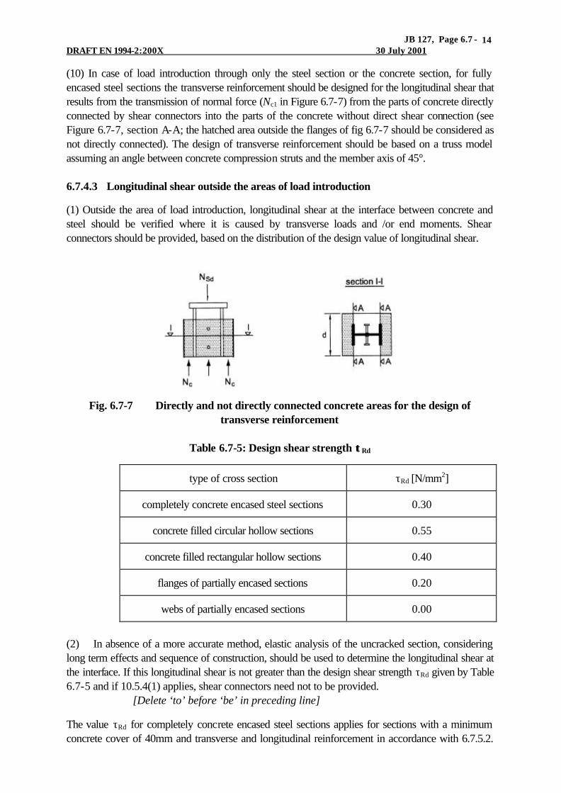
JB 127, Page 6.7 - DRAFT EN 1994-2:200X 30 July 2001
14
(10) In case of load introduction through only the steel section or the concrete section, for fully encased steel sections the transverse reinforcement should be designed for the longitudinal shear that results from the transmission of normal force (Nc1 in Figure 6.7-7) from the parts of concrete directly connected by shear connectors into the parts of the concrete without direct shear connection (see Figure 6.7-7, section A-A; the hatched area outside the flanges of fig 6.7-7 should be considered as not directly connected). The design of transverse reinforcement should be based on a truss model assuming an angle between concrete compression struts and the member axis of 45°. 6.7.4.3 Longitudinal shear outside the areas of load introduction
(1) Outside the area of load introduction, longitudinal shear at the interface between concrete and steel should be verified where it is caused by transverse loads and /or end moments. Shear connectors should be provided, based on the distribution of the design value of longitudinal shear.
Fig. 6.7-7 Directly and not directly connected concrete areas for the design of
transverse reinforcement
Table 6.7-5: Design shear strength ττ Rd
type of cross section τRd [N/mm2]
completely concrete encased steel sections 0.30
concrete filled circular hollow sections 0.55
concrete filled rectangular hollow sections 0.40
flanges of partially encased sections 0.20
webs of partially encased sections 0.00
(2) In absence of a more accurate method, elastic analysis of the uncracked section, considering long term effects and sequence of construction, should be used to determine the longitudinal shear at the interface. If this longitudinal shear is not greater than the design shear strength τRd given by Table 6.7-5 and if 10.5.4(1) applies, shear connectors need not to be provided. [Delete ‘to’ before ‘be’ in preceding line]
The value τRd for completely concrete encased steel sections applies for sections with a minimum concrete cover of 40mm and transverse and longitudinal reinforcement in accordance with 6.7.5.2.

JB 127, Page 6.7 - DRAFT EN 1994-2:200X 30 July 2001
15
For greater concrete cover and adequate reinforcement, higher values of τRd may be used. Unless verified by tests, for completely concrete encased sections the increased value βc ⋅τRd may be used, with βc given by : [This para. needs a number]
5,2102,01z
min,zzc ≤
−+=β
c
cc (6.7-24)
where :
cz is the nominal value of concrete cover in [mm], see Figure 6.7-1a ; cz,min is the minimum concrete cover in accordance with 6.7.5.1(2) with cz,min= 40mm. (3) Unless otherwise verified, for partially encased I-sections with transverse shear due to bending around the weak axis, shear connectors (e.g. headed studs) should be provided. If the resistance to transverse shear is not be taken as only the resistance of the structural steel, then the required transverse reinforcement for the shear force Vc,Sd according to 6.7.3.2(3) should be welded to the web of the steel section or should pass through the web of the steel section. 6.7.5 Detailing Provisions
6.7.5.1 Concrete cover of steel profiles and reinforcement
(1)P For fully-encased steel sections at least a minimum cover of reinforced concrete shall be provided to ensure the safe transmission of bond forces, the protection of the steel against corrosion, spalling of concrete and an adequate fire resistance, see prEN 1994-1-2:20XX.
(2) The concrete cover to a flange of a fully-encased steel section should be not less than 40mm, nor less than one-sixth of the breadth b of the flange.
(3) The cover to reinforcement should be in accordance with section 4 of prEN 1992-1:2001. 6.7.5.2 Longitudinal and transverse reinforcement
(1) The longitudinal reinforcement in concrete-encased columns which is allowed for in the resistance of the cross-section should be not less than 0.3% of the cross-section of the concrete. In concrete-filled hollow sections normally no longitudinal reinforcement is necessary, if design for fire resistance is not required.
(2) The transverse reinforcement in fully or partially concrete-encased columns according to 6.7.1(1) should be designed according to clause 9.3.3 of prEN 1992-1:2001. [Clause 9.4.2 ? There is no clause 9.3.3]
(3) For the spacing of the longitudinal and transverse reinforcement of fully or partially concrete encased members, section 9.3 of prEN 1992-1:2001 applies. [Clause 9.4.2, not section 9.3 ?]

JB 127, Page 6.7 - DRAFT EN 1994-2:200X 30 July 2001
16
Fig. 6.7-8 Effective perimeter c of a reinforcing bar (4) The clear distance between longitudinal reinforcing bars and the structural steel section may be smaller that required by (3), even zero. In this case, for bond the effective perimeter c of the reinforcing bar should be taken as half or one quarter of its perimeter, as shown in Figure 6.7-8 at (a) and (b) respectively.
(5) For fully or partially concrete encased members, where environmental conditions are class X0 according to Table 4.1 of prEN 1992-1:2001 and longitudinal reinforcement is neglected in design, a minimum longitudinal reinforcement of diameter 8 mm and 250 mm spacing and a transverse reinforcement of diameter 6 mm and 200 mm spacing should be provided. Alternatively welded mesh reinforcement of diameter 4 mm may be used.

JB 128 Page DRAFT EN 1994-2:200X 30 July 2001 _________________________________________________________________________________________
1
6.8 Fatigue [See the drafting notes at the start of Section 6, paper JB 125] 6.8.1 General (1)P The resistance of composite structures to fatigue shall be verified where the structures are subjected to repeated fluctuations of stresses.
(2)P Design for the limit state of fatigue shall ensure, with an acceptable level of probability, that during its entire design life, the structure is unlikely to fail by fatigue or to require repair of damage caused by fatigue.
(3) The fatigue assessment procedures assume that the structure conforms with the other limit state requirements, the stress limits according to 7.2.2 and the limitations according to clause 1.3 of EN1993-1-9:200X. For headed stud shear connectors in the serviceability limit state the maximum longitudinal shear force per connector should not exceed 0,6 PRk under the characteristic combination of actions where PRk is the characteristic resistance of the shear connector according to 6.6.3.1 and 6.6.4. [Change to: ‘..not exceed 0.75PRd under the characteristic combination of actions where
PRd is the design resistance of the connector.’ Reason: neither 6.6.3.1 nor 6.6.4 give
characteristic resistances] (4)P Fatigue load models shall follow clauses XX and XX of EN 1993-2:200X.
(5) For road bridges simplified methods according to EN 1992-2: 200X and EN 1993-2:200X, based on Fatigue Load Model 3 of clause XX of EN 1991-3:200X may be used for verifications of fatigue resistance. 6.8.2 Partial safety factors for fatigue assessment
(1) Partial safety factors γMf for fatigue strength are given in 3.4 of EN 1993-1-9:20XX for steel elements and in 6.8 of EN 1992-1-1:2001 for concrete and reinforcement. For headed stud shear connectors γMf = 1,0 should be used. For the welds of other types of shear connectors clause 3.4 of EN 1993-1-9:20XX applies.
(2) Partial safety factors γFf for fatigue loading are given in 3.3 of EN 1993-1-9:20XX for steel elements and stud connectors and in 6.8 of EN 1992-1-1:2001 for concrete and reinforcement. [Should not these factors be in EN 1991? Clause 6.8 of EN 1992-1 does not give a factor γFf ] 6.8.3 Fatigue strength
(1) The fatigue strength for structural steel and welds for shear connectors other than headed studs is given in Section 6 of EN 1993-1-9:20XX. [‘is given in’ is not normative. Change it to ‘should be taken from’ as in para. (2)]

JB 128 Page DRAFT EN 1994-2:200X 30 July 2001 _________________________________________________________________________________________
2
(2) The fatigue strength of reinforcing steel and prestressing steel should be taken from chapter 6.8 of EN 1992-1-1:2001. [Delete ‘chapter’]
(3) The fatigue strength curve of an automatically welded headed stud according to 6.6.3.1 is shown in Fig. 6.8-1 and given for normal weight concrete by
NN mc
mR )()( τ∆=⋅τ∆ (6.8-1)
where ∆τR is the fatigue strength,
∆τc is the reference value at 2 million cycles with ∆τc=95N/mm2
m is the slope of the fatigue strength curve with the value m=8,
N is the number of stress range cycles.
Figure 6.8-1:Fatigue strength curve for headed studs in solid slabs
(4) For studs in lightweight–aggregate concrete with a density class according to section [Section] 10 of EN 1992-1-1:2001 the fatigue strength should be determined in accordance with (3) with ∆τR replaced by ∆τRL and ∆τc replaced by ∆τcL, where ∆τRL and ∆τcL are given by 2,2/)classDensity(ccLRRL =ητ∆η=τ∆τ∆η=τ∆ (6.8-2)
Note: The value for m is under discussion 6.8.4 Internal forces and stresses for fatigue verification
6.8.4.1 General
(1) Internal forces and moments should be determined by elastic global analysis of the structure under fatigue loading in accordance with 5.4.1 and 5.4.2. Dynamic response of the structure or impact effects should be considered when appropriate. [Not ‘shall’ because an AR]
(2) The calculation of stresses should be based on the assumption given in 7.2.1. [7.2.1 does not clearly state any one assumption, so give para. number] (3) Internal forces should be determined for the fatigue load model specified by the relevant authority or the client.

JB 128 Page DRAFT EN 1994-2:200X 30 July 2001 _________________________________________________________________________________________
3
6.8.4.2 Structural steel, reinforcement and concrete (1) Paragraphs (1) to (5) provide a simpler alternative to 6.8.4.1 for verification based on nominasl stress ranges according to 6.8.5. [This alternative is suggested: ‘For verification based on nominal stress ranges according to 6.8.5, and as a simpler alternative to 6.8.4.1, internal forces and stresses based on 6.8.4.2.(2) to (6) may be used.’]
(2) For the simplified assessment the maximum and minimum effective bending moments and internal forces due to the relevant fatigue loading are given by [Replace by: ‘should be calculated from’]
fmax,permE,fmax, MMM λ+= (6.8-3)
fmin,permE,fmin, MMM λ+= (6.8-4)
where
Mperm is the most adverse bending moment in the composite section for the characteristic combination neglecting traffic loads but with the combination factor [‘factors’ as there may be more than one factor] where fatigue loading is the leading action,
Mmax,f is the maximum bending moment due to the relevant fatigue loading,
Mmin,f is the minimum bending moment due to the relevant fatigue loading,
λ is the damage equivalent factor according to (7).
(3) Unless a more precise method is used, the effect of tension stiffening of concrete between cracks on the stress ranges in reinforcement may be taken into account as follows. [colon replaced by full point] In regions where the effective global bending moments Mmax,f,E and Mmin,f,E cause tension in the concrete slab the stresses in reinforcement are given by
max
E,fmax,max,sE,fmax, M
Mσ=σ (6.8-5)
max
E,fmin,max,sE,fmin, M
Mσ=σ (6.8-6)
where σs,max is the stress in the reinforcement due to Mmax,
Mmax is the bending moment in the composite section for the characteristic combination of actions according to EN 1990:200X with variable load [‘the fatigue loading’ ?] as the leading action, and
Mmin,f,E and Mmax,f,E are defined in (2). The stress σs,max is given by s0max,,smax,s σ∆+σ=σ (6.8-7)
where σs,max,0 is the stress in the reinforcement due to Mmax calculated neglecting concrete in tension and ∆σs is given in 7.4.3.

JB 128 Page DRAFT EN 1994-2:200X 30 July 2001 _________________________________________________________________________________________
4
(4) If Mmin,f,E according to (2) causes compression in the concrete slab, the stresses σs,min,E [σmin,f,E ?] in reinforcement and structural steel should be determined with the cross-section properties of the uncracked section using the modular ratio n0 for short term loading for the bending moment Mmin,f. [In Fig. L.9 of ENV 1994-2, this bending moment is Mmin,f,E. Which is
correct ?] (5) The stress ranges in the reinforcement should be calculated with the stresses σmax,f,E and σmin,f,E according to (3) and (4) from
E,fmin,E,fmax,E σ−σ=σ∆ (6.8-8)
Where a member is subjected to combined global and local effects the separate effects should be considered. (6) The stress range ∆σE according to 6.8.5 in structural steel of cracked sections may be determined by neglecting effects of tension stiffening of concrete and using the second moment of area I2 according to 5.4.2.2(1)
(7) For steel elements the factor λ=λ1⋅⋅λ2⋅λ3⋅.....λn) is given in 4.4 of EN1993-1-9:20XX and for reinforcement λ=λs is given in XXX of EN 1992-1:2001.
[A possible replacement for paragraphs (5) to (7) is given, as new paragraphs (5) to (8): (5)For structural steel at cracked sections, σmax,f,E and σmin,f,E may be determined by neglecting effects of tension stiffening of concrete and using the second moment of area I2 according to 5.4.2.2(1) .
(6) The stress ranges in reinforcement and structural steel should be calculated with the stresses σmax,f,E and σmin,f,E according to (3) to (5) from
E,fmin,E,fmax,E σ−σ=σ∆ (6.8-8)
(7) Where a member is subjected to combined global and local effects the separate effects should be considered. (8) For steel elements in buildings the factor λ=λ1⋅⋅λ2⋅λ3⋅.....λn is given in 4.4 of EN 1993-1-9:200X. [From 6.8.4.2(7) of the Third Draft, with ref. to EN 1992-1 removed, as that code does not give λs]
(8) For bridges, for the simplified verification according to 6.8.5, the factor λ=λ1⋅⋅λ2⋅λ3⋅.....λn is given for steel elements in XXX of EN1993-2:200X. For reinforcement and prestressing steel λ=λs is given in XXX of EN 1992-2:200X.
JB 128 Page DRAFT EN 1994-2:200X 30 July 2001 _________________________________________________________________________________________
5
(9) Where a member in a bridge is subjected to combined global and local effects, and unless a more precise method is used, the equivalent constant amplitude stress due to global effects should be added to the equivalent constant stress range due to local effects, where the local effects should be determined with the correction factor λloc according to XXX of YYY.. [Wording changed, to avoid repetition of (7)] 6.8.4.3 Shear connection
(1)P The longitudinal shear per unit length shall be calculated by elastic analysis.
(2)P In members where cracking of concrete occurs the effects of tension stiffening shall be taken into account in accordance with EN 1992-1:2001. [‘P’ should be removed and ‘shall’ changed to ‘may’ because this para. is modified by para. (3), and an AR cannot modify a P clause. A more precise reference to EC2 is required. Clause 7.3.4(2)?]
(3) If for simplification the effects of tension stiffening of concrete are neglected, the longitudinal shear forces should be determined using the cross-section properties of the uncracked section.
(4) For verification of stud shear connectors based on nominal stress ranges the equivalent constant stress range ∆τE,2 for 2 million cycles is given by
τ∆λ=τ∆ v2,E (6.8-9)
where λv is the damage equivalent factor depending on the spectra and the slope m of the fatigue strength curve and ∆τ is the stress range due to fatigue loading.
(5) Where for stud connectors no value for λv is specified, the damage equivalent factor should be
determined in accordance with Annex A of EN 1993-1-9:20XX using the relevant slope m=8 of the fatigue strength curve of the stud connector, given in 6.8.3.
(6) The equivalent constant amplitude shear stress range in welds of other types of shear connection should be calculated in accordance with EN 1993-1-9:20XX. [A clause ref. to EN 1993-1-9 is needed.]
(7) The damage equivalent factor λv for headed studs should be determined in accordance with XXX of EN 1993-2:20XX but using the factor λv,1 instead of λ1. In the formulae in XX of EN 1993-2 the factors λ2 to λ4 should be calculated using the relevant slope m = 8 of the fatigue strength curve for headed studs, given in 6.8.3. [Drafting note: the value for m is under discussion]
(8) For stud connectors in road bridges of span up to 100 m the factor λv,1=1,55 may be used. For stud connectors in railway bridges the factor λv,1 may be taken from figure 6.8-2.

JB 128 Page DRAFT EN 1994-2:200X 30 July 2001 _________________________________________________________________________________________
6
6.8.5 Fatigue assessment based on nominal stress ranges
(1) The fatigue assessment for structural steel should follow 5.2 of EN 1993-1-9:20XX.
(2) The fatigue assessment for reinforcement should be made by checking the criterion
MfREFf /)N( γσ∆≤σ∆γ ∗ (6.8-10)
Figure 6.8-2: Values λλ v,1 for load model 71 according to EN 1991-3:200X
where ∆σE is the equivalent constant amplitude stress ranges and ∆σR(N*) is the reference values of fatigue strength at N* cycles according to 6.8.5 of EN 1992-1-1:2001.
(3) The verification for concrete in compression should follow 6.8 of EN 1992-1:2001.
(4) For stud connectors welded to a steel flange that is always in compression under the characteristic combination of actions, the fatigue assessment should be made by checking the criterion
Mfc2,EFf / γτ∆≤τ∆γ (6.8-11)
where ∆τE,2 is defined in 6.8.4.3(4) and ∆τc is the reference value of fatigue strength at 2 million cycles according to 6.8.3. The stress range ∆τ in the stud should be determined with the cross-section area of the shank of the stud using the nominal diameter d of the shank.
(5) Where the maximum stress in the steel flange to which stud connectors are welded is tensile under the characteristic combination of actions, the interaction at any cross-section between shear stress range ∆τE in the weld of stud connectors and the normal stress range ∆σE in the steel flange should be verified using the following interaction expressions.
3,1// Mfc
2,EFf
Mfc
2,EFf ≤γτ∆τ∆γ
+γσ∆
σ∆γ (6.8-12)
0,1/
0,1/ Mfc
2,EFf
Mfc
2,EFf ≤γτ∆τ∆γ
≤γσ∆
σ∆γ (6.8-13)

JB 128 Page DRAFT EN 1994-2:200X 30 July 2001 _________________________________________________________________________________________
7
where the stress range in the flange ∆σE,2 is given by clause 4.4 of EN1993-1-9:20XX and the reference value of fatigue strength ∆σc is given in clause 8 of EN1993-1-9:20XX by applying category 80. The stress ranges ∆τE,2 and ∆τc are defined in (4) and 6.8.3(3), respectively. Interaction (6.8-12) should be checked for the maximum value of ∆σE,2 and the corresponding value ∆τE,2 as well as for the combination of the maximum value of ∆τE,2 and the corresponding value of ∆σE,2. Unless taking into account the effect of tension stiffening of concrete by more accurate methods, the interaction criterion should be verified with the corresponding stress ranges determined with cracked and uncracked cross-section properties. 6.9 Tension members in composite bridges (1) A concrete tension member in a composite system should be designed in accordance with Sections 6 and 9 of EN 1992-1 and clause ??? of EN 1992-2. For prestressing by tendons the effect of different bond behaviour of prestressing and reinforcing steel should be taken into account according to 8.10 of EN 1992-1:200X. [from 4.7.2(1)] NOTE:‘Composite system’ is defined in 5.4.2.9 (2) For tension members in half-through bridges or bowstring arch bridges where the tension member is simultaneously acting as a deck and is subjected to combined global and local effects, the design shear resistance for local vertical shear and for punching shear due to permanent loads and traffic loads should be determined according to 6.2 and 6.4 of EN 1992-1:200X by taking into account the normal force of the reinforced concrete element according to 5.4.2.9(3) and (6). [from 4.7.2(5)] (3) At the ends of concrete tension members, for the introduction of the normal force, a concentrated group of shear connectors designed according to 6.6 should be provided. The shear connection should be able to transfer the design value of the normal force of the concrete tension element over a length 1.5 b, where b is the larger of the outstand of the concrete member and half the distance between adjacent steel elements. Where the shear connectors are verified for a normal force determined by 5.4.2.9(3)P, an additional partial safety factor γF should be applied, to take into
account the uncertainties of the tensile strength of concrete. In absence of specific information, it is recommended that γF = 1.25.
[From 4.7.2(6)] (4)P Provision shall be made for internal forces and moments from members connected to the ends of a composite tension member to be distributed between the structural steel and reinforced concrete elements. [From 4.7.3(5)P] (5) For composite tension members subject to tension and bending a shear connection should be provided according to 6.6. [From 4.7.3(4)] (6) For composite tension members such as diagonals in trusses, the introduction length for the shear force should not be assumed to exceed twice the minimum transverse dimension of the member. [From 4.7.3(6)]

Doc. : EC4-2-JPL 011 prEN 1994-2 : 200X (Draft 1, July 01) Page 7.1
7 Serviceability limit states
7.1 General
7.1.1 Scope (1)P A structure with composite members shall be designed and constructed such that all relevant serviceability limit states are satisfied according to the Principles of 3.4 of prEN1990-200x.
(2) The verification of serviceability limit states should be based on the criteria given in 3.4(3) of EN1990-200x.
(3) Serviceability limit states for composite plates are covered in section 9.
(4) In order to ensure the performance required, the bridge or parts of the bridge may be classified into design categories for serviceability verification, according to XXX of prEN 1992-2:200x for both the construction phases and for persistent situations. The appropriate category should be agreed with the client. [Drafting note: Waiting for the content of prEN 1992-2 and prEN 1993-2] 7.2 Stresses
7.2.1 General
(1)P Calculation of stresses for beams at the serviceability limit state should take into account the following effects, where relevant:
- shear lag ; - creep and shrinkage of concrete ; - cracking of concrete and tension stiffening of concrete ; - sequence of execution ; - increased flexibility resulting from significant incomplete interaction due to slip of shear connection ; - inelastic behaviour of steel and reinforcement, if any ; - prestressing ; - temperature effects.
(2) Shear lag may be taken into account according to 5.4.1.2
(3) Unless a more accurate method is used, effects of creep and shrinkage may be taken into account by use of modular ratios according to 5.4.2.3.
(4) In cracked sections the primary effects of shrinkage may be neglected when verifying stresses
(5)P In section analysis the tensile strength of concrete shall be neglected.
(6) The influence of tension stiffening of concrete between cracks on stresses in reinforcement and prestressing steel should be taken into account. Unless more accurate methods are used, the stresses in reinforcement should be determined according to 7.4.3.

Doc. : EC4-2-JPL 011 prEN 1994-2 : 200X (Draft 1, July 01) Page 7.2
(7) The influences of tension stiffening on stresses in structural steel may be neglected.
(8) For bridges, calculation of stresses for beams at the serviceability limit state should take into account warping stresses, where relevant.
(9) Stresses in the concrete slab and its reinforcement caused by simultaneous global and local actions should be added.
[Drafting note: Waiting for the content of prEN 1992-2]
NOTE: As long as no ψ-factors are given in EN 1991-3:200x for the combination of local and global effects the combination factor ψ = 1 may be used. 7.2.2 Stress limitation for bridges
(1)P Excessive creep and microcracking shall be avoided by limiting the compressive stress in concrete.
(2) For concrete prestressed by tendons, the maximum compressive stress at transfer of prestressing forces into the deck should be limited in accordance with XXX of prEN 1992-2:200x
(3) For concrete prestressed by tendons, the compressive stress in the concrete under the infrequent combination of actions and the characteristic value of prestress should be limited in accordance with XXX of prEN 1992-2:200x unless the compression zone is confined by, for example, transverse reinforcement in excess of 1% of the volume of the compression zone. [Drafting note: Waiting for the content of prEN 1992-2 for load combination
(4)P The stress in reinforcing steel and in prestressing tendons shall be such that inelastic strains in the steel are avoided.
(5) The stress in prestressing tendons at infinite time under the quasi-permanent combination should be limited, after allowance for all losses, in accordance with XXX of prEN 1992-2:200x.
(6) The tensile stress in the ordinary reinforcement under the characteristic combination of actions should be limited to 0.9 ykf .
(7) For precast elements that are the subject of an adequate control system, (see Annex A2 of prEN 1992-1 2001), the value of the compressive stress given in XXX of prEN 1992-2:200x may be exceeded during construction by 10% if strict control of strength is provided and a check of loss of prestress at the time considered is made.
(8) The stresses in structural steel under the characteristic combination of actions should be in accordance with clause XXX of prEN 1993-2:200x.
(9) For serviceability limit states, forces applied to shear connectors should be limited according to 6.8.1.4. The size and spacing of shear connectors may be kept constant over any length where the design longitudinal shear per unit length does not exceed the design shear resistance by more than 10%.
[Drafting note for 7.2.2: Waiting for the content of prEN 1992-2 and prEN 1993-2]

Doc. : EC4-2-JPL 011 prEN 1994-2 : 200X (Draft 1, July 01) Page 7.3
7.3 Deformations
7.3.1 General (1) Deflections due to loading applied to the steel member alone shall be calculated in accordance with EN 1993-1-1:20xx.
(2) Deflections due to loading applied to the composite member shall be calculated using elastic analysis in accordance with section 5. 7.3.2 Beams in bridges
(1)P Deformations shall not adversely affect the drainage of water from the structure, and the use, efficiency, or appearance of the structure. Composite members shall be so proportioned that deflections of beams and sidesway are within acceptable limits.
(2)P Deformations during construction shall be controlled such that the concrete is not impaired during its placing and setting by uncontrolled displacements and the required long-term geometry is achieved.
(3) For railway bridges, clause G.3 of prEN 1991-3:2001 is applicable. For other bridges, limiting values of deformations in presence of traffic should, where relevant, be agreed with the client, together with the associated combinations of actions.
7.3.3 Vibration
(1) For the limit state of vibration see clauses 5.7 and 6.4 of prEN 1991-3:200x, 4.4.4 of prEN 1992-2:200x and clauses 4.7, 4.8 and 4.9 of prEN 1993-2:200x. [Drafting note: Waiting prEN 1992-2 and prEN 1992-2] 7.4 Cracking of concrete
7.4.1 General (1)P Cracking shall be limited to an extend that will not impair the durability, the proper functioning of the structure or cause its appearance to be unacceptable. Cracking is almost inevitable where reinforced concrete elements of composite members are subject to tension resulting from either direct loading or restrained of imposed deformations.
(2)P Cracks may also arise from other causes such as plastic shrinkage or expansive chemical reactions within the hardened concrete. Such cracks may be unacceptably large but the avoidance and control lie outside the scope.
(3)P Appropriate limits, taking account of the proposed function and nature of the structure and the costs of limiting crack width, shall be agreed with the client.
(4)P Limitation of cracks to acceptable width, and the avoidance of uncontrolled cracking between widely spaced bars, shall be achieved by ensuring that, at all sections likely to be subjected to tension due to restrained imposed permanent and variable deformations and/or direct loading, a minimum amount of bonded reinforcement is present, sufficient to ensure that the reinforcement will remain elastic and the crack width will be limited to the design crack width when single cracking occurs.

Doc. : EC4-2-JPL 011 prEN 1994-2 : 200X (Draft 1, July 01) Page 7.4
(5) Special crack limitation measures may be necessary for members subjected to exposure classes XA3, XD3 and XF4. The choice of appropriate measures will depend upon the nature of the aggressive chemical involved. (6) An estimation of crack width can be obtained from 7.3.4 of EN 1992-1:2001 where the stress σs should be calculated under consideration of the effects off tension stiffening. Unless a more precise method is used the stress σs may be determined according to 7.4.3(4).
(7) As a simplified and conservative alternative, crack width limitation to acceptable width can be achieved by ensuring a minimum reinforcement defined in 7.4.2, and bar spacing or diameters not exceeding the limits defined in 7.4.3.
(8) In the absence of specific requirements, it may be assumed that for exposure classes 2 to 4, according to XXX of prEN 1992-1:2001, limitation of the design crack width to 0,3 mm for reinforced concrete and 0,2 mm for composite bridges prestressed by tendons within the concrete slab will generally be satisfactory in respect of durability. Where there is normal reinforcement in the longitudinal direction and prestressing by tendons in the transverse direction the crack widths should be limited to 0,2 mm in the longitudinal direction. [Drafting note: Waiting what is said in prEN 1992-2 : 200x] Note: The design crack width can be agreed by the client or guidance may be given in the National annex.
(9) Application rules are given in 7.4.2 and 7.4.3 for design crack widths wk of 0,3 mm for reinforced concrete and 0,2 mm for prestressed concrete, for general use. For general use the reinforcing bars should have high-bond action, in accordance with 3.2 EN 1992-1:2001. For other design crack widths, reference should be made to XXX of EN 1992-2 : 200x.
(10) The minimum reinforcement according to 7.4.2 is adequate to control the crack width according to 7.4.1 (9) provided that it can be verified that under the relevant combination of actions for controlling the crack width, the concrete stress in the extreme fibre of the section does not exceed the mean value of the concrete tensile strength (σc ≤ fctm ).
(11) Where 7.4.1 (10) is not satisfied 7.4.2 and 7.4.3 should be applied.
(12) When composite action is effective after concrete hardening, effects of heat of hydration of cement and corresponding thermal shrinkage should be taken into account only during the construction stage for serviceability limit state. Unless a more precise method given in the National Annex is used, a temperature difference of 20K between the concrete section and the steel section (concrete cooler) corresponding to thermal shrinkage should be assumed to verify crack widths. Note: Other values for the temperature difference may be given in the National Annex 7.4.2 Minimum reinforcement
(1) Unless a more accurate method is used in accordance with 7.3.2(1)P of prEN 1992-1:2001, in all sections without prestressing by tendons to be subjected to significant tension due to restraint of imposed deformations (e.g. primary and secondary effects of shrinkage), in combination or not with effects of direct loading the required minimum reinforcement area As for the slabs of composite beams is given by:

Doc. : EC4-2-JPL 011 prEN 1994-2 : 200X (Draft 1, July 01) Page 7.5
scteff,ctcss / σ= AfkkkA (7.3) where : fct,eff is the mean value of the tensile strength of the concrete effective at the time when
cracks may first be expected to occur. Values of fct,eff =fctm may be obtained from section 3 of prEN 1992-1:2001 by taking as the class the strength at the time cracking is expected to occur. When the age of the concrete at cracking cannot be established with confidence as being less than 28 days, it is suggested that a minimum tensile strength of 3 N/mm2 be adopted;
k is a coefficient which allows for the effect of non-uniform self-equilibrating stresses
which may be taken as k=0.8 ; ks is a coefficient which allows for the effect of the reduction of the normal force of the
concrete slab due to initial cracking and local slip of the shear connection, which may be taken as ks=0.9;
kc is a coefficient which takes account of the stress distribution within the section
immediately prior to cracking and is given by :
0,13.0)2(/1
1
occ ≤+
+=
zhk (7.4)
hc is the thickness of the concrete flange, excluding any haunch or ribs, and
zo is the vertical distance between the centroids of the uncracked and unreinforced concrete flange and the uncracked unreinforced composite section, calculated using the modular ratio n0 for short term effects,
σs is the maximum stress permitted in the reinforcement immediately after cracking. For reinforcement steel, this may be taken as the characteristic yield strength fsk of the reinforcement. A lower value depending on the bar size, however may be needed to satisfy the required crack width limits. This value is given in Table 7.2.
Act is the area of the tensile zone (caused by direct loading and primary effects of shrinkage) immediately prior to cracking of the cross section. For simplicity the area of the concrete section within the effective width should be used.
Table 7.2 Maximum bar diameters for high bond bars
maximum bar diameter ∅ ∗s (mm) for design crack width steel stress
σs [N/mm2]
wk=0,4mm wk=0,3mm wk=0,2mm
160 40 32 25 200 32 25 16 240 20 16 12 280 16 12 8 320 12 10 6 360 10 8 5 400 8 6 4 450 6 5 -

Doc. : EC4-2-JPL 011 prEN 1994-2 : 200X (Draft 1, July 01) Page 7.6
(2) The maximum bar diameter for the minimum reinforcement may be modified to a value
∅s = ∅ ∗s fct,eff / fct,o (7.5)
where :
∅s is the adjusted maximum bar diameter ;
∅ ∗s is the maximum bar size given in Table 7.2 ;
fct,eff is defined in (1) ;
fct,0 is a reference strength of 2.5 N/mm2.
(3) Half of the required minimum reinforcement should be placed between mid-depth of the slab and the face subjected to the greater tensile strain.
(4) The minimum reinforcement according to (1) and (2) should be placed where under the characteristic combination of actions the reinforced concrete resists tensile stress, and for prestressed concrete, where the stresses are tensile. (5) Where bonded prestressing tendons are used, the contribution of prestressing steel to the limitation of crack width may be taken into account. (6) Where bonded prestressing tendons are used, the minimum reinforcement area As for the slabs of composite beams is given by: scteff,ctcss / σ= AfkkkA p1Aξ− (7.31)
where: ξ1 is the adjusted ratio of bond strength according to 7.4.3 (5), Ap area of prestressing steel within an area of not more than 300 mm around the steel
reinforcement in the tensile zone 7.4.3 Control of cracking due to direct loading (1) This clause is applicable in regions where the reinforcement required to provide resistance to bending at ultimate limit states exceeds the minimum reinforcement required by 7.4.2.
(2) Where at least the minimum reinforcement given by 7.4.2 is provided, the limitation of crack widths to acceptable values and the avoidance of uncontrolled cracking between widely spaced bars, may generally be achieved by limiting bar spacing or bar diameters. Maximum bar diameter and maximum bar spacing depend on the stress σs in the reinforcement and the design crack width. Maximum bar diameters are given in Table 7.2 and maximum bar spacing in Table 7.3.

Doc. : EC4-2-JPL 011 prEN 1994-2 : 200X (Draft 1, July 01) Page 7.7
Table 7.3 Maximum bar spacing for high bond bars
maximum bar spacing (mm) for design crack width steel stress σs N/mm2 wk=0,4mm wk=0,3mm wk=0,2mm
160 300 300 200 200 300 250 150 240 250 200 100 280 200 150 50 320 150 100 - 360 100 50 -
(3) The internal forces should be determined by elastic analysis in accordance with section 5 taking into account the effects of cracking of concrete. The stresses in the reinforcement should be determined taking into account effects of tension stiffening of concrete between cracks. Unless a more precise method is used, the stresses may be calculated according to (4).
(4) In composite beams where the concrete slab is assumed to be cracked and not prestressed by tendons, stresses in reinforcement increase due to the effects of tension stiffening of concrete between cracks compared with the stresses based on a composite section neglecting concrete. The tensile stress in reinforcement σs due to direct loading may be calculated from
so,ss σ∆+σ=σ with sst
ctms
4.0
ρα=σ∆
f (7.6)
where : σso is the stress in the reinforcement caused by the internal forces acting on the composite
section, calculated neglecting concrete in tension ; ∆σs is the increase of stress due to tension stiffening of concrete ; fctm is the mean tensile strength of the concrete ; ρs is the reinforcement ratio, given by ρs= (As /Act) ; Act is the effective area of the concrete flange within the tensile zone; for simplicity the area
of the concrete section within the effective width should be used ; As is the total area of all layers of longitudinal reinforcement within the effective area Act ;
αst is given by αst = A I / (Aa Ia), where A and I are area and second moment of area, respectively, of the composite section neglecting concrete in tension and profiled sheeting, if any, and Aa and Ia are the corresponding properties of the structural steel section.
(5) Where bonded prestressing tendons are used, the stresses σs in reinforcement may be calculated by:
−+=
efftoteffp
ctmIIss ,
,,
11f40
ρρσσ (7.61)
with:

Doc. : EC4-2-JPL 011 prEN 1994-2 : 200X (Draft 1, July 01) Page 7.8
stefftot
ctmse
IIs
,
αρσσ
,
f40+= (7.62)
where the symbols are defined in 7.4.3 (4) and as follows : σs is the stress in the reinforcement caused by external moments, with:
ρp,effct
p21s
A
AA ξ+= ρtot,eff =
+A A
As p
ct ,
where: Ap is the area of the tendons within the effective area Act , ξ1 is the adjusted ratio of bond strength taking into account the different diameters of
prestressing and reinforcing steel and may be calculated by : ξ ξφφ1= s
p
.
If only prestressing steel is used then ξ1 should be taken as 1,0. φs is the largest diameter of steel reinforcement, φp is the equivalent diameter of prestressing steel; φp = 1,6 Ap for tendons with several strands or wires,
φp = 1,75φwire for single strands with 7 wires, φp = 1,20φwire for single strands with 3 wires, ξ is the ratio of mean bond strength of prestressing steel and high bond reinforcing
steel. In the absence of appropriate data ξ may be taken from table 7.4 :
Table 7.4 Nominal ratios ξξ for crack control.
Type of tendon Pretensioned members
Posttensioned members
smooth prestressing steel --- 0,4 7-wire strands 0,6 0,5 ribbed prestressing wires 0,8 0,7 ribbed prestressing bars 1,0 0,8
[Drafting note: Waiting for the content of prEN 1992-2]

Doc. : EC4-2-JPL 011 prEN 1994-2 : 200X (Draft 1, July 01) Page 7.9
7.5 Filler beam decks
7.5.1 General (1) The actions effects for the serviceability limit states should be determined according to paragraphs1 to 5 and 7 to 8 of 5.4.2.11. 7.5.2 Cracking of concrete (1) The principles and applications rules of 7.4.1 should be considered.
(2) For the reinforcing bars or wires in the direction of the steel beams within the whole thickness of the deck, 7.5.3 and 7.5.4 should be apply. 7.5.3 Minimum reinforcement (1) The minimum reinforcement should be determined in accordance with XXX of prEN 1992-2:200x, using a value kc = 0.4.
[Drafting note: Waiting for the content of prEN 1992-2] 7.5.4 Control of cracking due to direct loading (1) XXX of prEN 1992-2:200x should be applied. The stresses in the reinforcenment should be calculated by using the cross-section properties of the cracked composite section with the second moment of area I2 according to 5.4.2.2 (1).
[Drafting note: Waiting for the content of prEN 1992-2]

CEN/TC250/SC4/PT2 EC4-2BHJ 021 Bernt Johansson 2001-10-24
8 Decks with precast concrete slabs 8.1 General (1)P This Section 8 deals with reinforced or prestressed precast concrete slabs or planks, depth flanges of bridge decks or as partial depth slabs acting with insitu concrete. (2)P The precast bridge slab shall be designed in accordance with 5.4.9 of EN 1992-2:200X and also for composite action with the steel beam. Drafting note: Awaiting progress on EN 1992-2 the references will be specified. (3) Relevant tolerances should be given in the project specification. 8.2 Actions (1) Clauses 7.3.2.1(2) and 7.3.2.1(4) are applicable to precast elements acting as permanent formwork. These minimum loads are not necessarily sufficient and the requirements of the construction method should be taken into account. Drafting note: Awaiting progress on EN 1994-2 the references will be updated. 8.3 Design, analysis and detailing of the bridge slab (1) The precast slab together with any insitu concrete should be designed as continuous in both the longitudinal and the transverse directions. The joints between slabs should be designed to transmit membrane forces as well as bending moments and shears. Compression perpendicular to the joint may be assumed to be transmitted by contact pressure if the joint is filled with mortar or glue or if it is shown by tests that the mating surfaces are in sufficiently close contact. (2) For the use of stud connectors in groups, see 6.4.1.5(4). Drafting note: Awaiting progress on EN 1994-2 the references will be updated. (3) The stepped distribution of shear forces in 4.5.3.2(104) of EN 1992-1-1:200X may be used provided that the limitations in 6.1.3(2) are observed. Drafting note: Awaiting progress on EN 1992-1-1 the references will be specified. 8.4 Joints between steel beam and concrete slab 8.4.1 Bedding and tolerances (1)P Where precast slabs are supported on steel beams without bedding the influence of the vertical tolerances of the bearing surfaces shall be considered. 8.4.2 Corrosion (1) A steel flange under precast slabs without bedding should have the same corrosion protection as the rest of the steelwork but for a top coating provided after erection. Bedding with the purpose of protecting against corrosion may be designed to be not loadbearing.

CEN/TC250/SC4/PT2 EC4-2BHJ 021 Bernt Johansson 2001-10-24
8.4.3 Shear connection and transverse reinforcement (1) The shear connection and transverse reinforcement should be designed in accordance with the relevant clauses of Section 6 and 7. (2) If shear connectors welded to the steel beam project into recesses within slabs or joints between slabs, which are filled with concrete after erection, the detailing and the properties of the concrete should be such that it can be cast properly. (3) In absence of relevant experience the minimum thickness of infill around such shear connectors should be at least 25mm. (4) If shear connectors are arranged in groups, sufficient reinforcement should be provided near each group to prevent premature local failure in either the precast or the insitu concrete.

CEN/TC250/SC4/PT2 EC4-2BHJ 021 Bernt Johansson 2001-10-24
9 Composite plates in bridges 9.1 General (1)P This section 9 is valid for composite plates consisting of a nominally flat plate of structural steel connected to a site cast concrete slab by headed studs. Double skin plates or other types of connectors are not covered. The intended use of the composite plate is as a flange in a bridge deck carrying transverse loads as well as in-plane forces, or as a bottom flange in a box girder. (2) The steel plate should be supported during casting either permanently or by temporary supports in order to limit its deflection to less than 0,05 times the slab thickness unless the additional weight of concrete is taken into account. (3) When determining the effective width according to 6.2.2, b0 should be taken as 2aw with aw as defined in 9.4(5). (4) For global analysis, clauses 5.1 and 5.4 apply. 9.2 Design for local effects (1) Local effects are bending moments and shears caused by transverse loads on the plate acting as an one- or two-way slab. For the purpose of analysis of local action effects the slab may be assumed elastic and uncracked. A top flange of an I-girder need not be designed as composite in the transverse direction. (2) The concrete and the steel plate may be assumed to act compositely without slip. The resistance to bending and vertical shear should be verified as for a reinforced concrete slab where the steel plate is considered as reinforcement. (3) The design resistance for shear in xxx and xxxx of EN 1992-1-1:200x are applicable. The plate may be considered as reinforcement if the distance, in two perpendicular directions, between shear connectors does not exceed three times the slab thickness.
Drafting note: Awaiting progress on EN 1992-1-1 the references will be specified. 9.3 Design for global effects (1)P The composite plate shall be designed to resist all forces from axial loads and global bending of all longitudinal girders or cross-girders that it forms part of. (2) The design resistance to in-plane compression may be taken as the sum of the design resistances of the concrete and the steel plate within the effective width according to 6.2.2 provided that the steel plate is connected to the concrete according to 6.7.10. Reduction in strength due to buckling should be considered according to xxx of EN 1992-1-1:200x, if appropriate.
Drafting note: Awaiting progress on EN 1992-1-1 the reference will be specified.

CEN/TC250/SC4/PT2 EC4-2BHJ 021 Bernt Johansson 2001-10-24
(3) The design resistance for tension should be taken as the sum of the design resistances of the steel plate and the reinforcement within the effective width according to 6.2.2 (4) Interaction with local load effects should be considered for the shear connectors as stated in 9.4 (1)P. Otherwise it need not be considered. 9.4 Design of shear connectors (1)P Resistance to fatigue and requirements for serviceability limit states shall be verified for the combined local and simultaneous global effect. Connectors that carry loads both longitudinally and transversely may be verified for the vector sum of the simultaneous forces on the connector. (2) The design resistance of stud connectors in 6.7.4 and 6.7.5 may be used provided that the concrete slab has bottom reinforcement with area not less than 0,002 times the concrete area in each of two perpendicular directions according to 6.7.10.1(1). (3) The detailing rules of 6.7.10 are applicable. (4) For wide girder flanges the distribution of longitudinal shear due to global effects for serviceability and fatigue limit states may be determined as follows in order to account for slip and shear lag. The longitudinal force PSd on a connector at distance x from the nearest web may be taken as
Pvn
nn
xbSd
Sd w=
−
−
+
−
3 85 3 1 0150 17 2
, ,,
(9.1)
where νSd is the design longitudinal shear flow due to global effects, n is the total number of connectors of the same size per unit length of girder within
the width b in Fig. 9.1, provided that the number of connectors per unit area does not increase with x,
nw is the number of connectors per unit length placed within a distance from the web
aw equal to the larger of 10tf and 200 mm, b is equal to half the distance between adjacent webs or the distance between the
web and the free edge of the flange. In case of a flange projecting up to aw outside the web, n and nw may include the connectors placed on the flange. For efficiency, nw should be as high as possible and the spacing of the connectors should be small enough to avoid premature local buckling of the plate, see 6.7.10.5(2).

CEN/TC250/SC4/PT2 EC4-2BHJ 021 Bernt Johansson 2001-10-24
tf
bx
a aw w
nw
n
Ps
Figure 9.1: Definition of notations in equation (9.1)

Draft 1 Page 1 2001–MM-DD prEN 1994-2: 200X
Paper BK-006/10/25/01
10. Execution [Drafting Note: Only internal changes to ENV-text are indicated. General clauses and compatibility with Part 1 (numbering of clauses) will follow the updated text of Section 10 of Part 1]
10.2 Sequence of construction (3) The rate and sequence of concreting should be specified to be such that partly matured concrete is not damaged as a result of limited composite action occurring from deformation of the steel beams under subsequent concreting operations. Wherever possible, deformation should not be imposed on a shear connection until the concrete has reached a cylinder strength of at least 20 N/mm2.
10.3 Accuracy during construction, and quality control
10.4.1 Deflection during and after concreting (1)P Clause 7,3 is applicable. (2) The formwork and its supports should be capable of transferring the load and effects rep. of concreting to the steelwork or other supports without distress and in accordance with the design assumptions. .
10.4.2 Shear connection
10.4.3.1 Headed studs rep.
(1)P Arc stud welding shall be in accordance with ?prEN ISO 14555 'Welding-Arc stud welding of metallic materials' and ?prEN ISO 13918 'Welding-Studs for arc stud welding'.
10.4.3.2 Hoops and block connectors (1)P The welding of hoops and block connectors shall be in accordance with the relevant clauses of EN 1992-1-1:XXXX and EN 1993-1-1:XXXX. (2)P Hoops that shall be welded shall comply with the conditions of weldability given in EN 1992-1-1:XXXX.
10.4.3.3 Friction grip bolts . (1)P The interface between the steel member and the concrete flange shall be free of oil, dirt, rust, loose mill scale, burrs and other defects which would prevent a uniform sealing between the two elements, or would interfere with the development of friction between them. (2) The method should be in accordance with the relevant clauses of Section 7 of EN 1993-1-1:XXXX.
10.4.3.4 Corrosion protection in the interface (1) Does not apply. (2) Corrosion protection as applied to the steelwork should extend at least 50 mm into the interface, except that any final site coat may normally be omitted. 10.4.3.5 Surface condition (1) For composite columns and filler beam decks, the surface of the steel section, in contact with the concrete filling or encasement should be unpainted and free from oil, grease and loose scale or rust.

JB 129 Page DRAFT EN 1994-2:200X 30 July 2001 _________________________________________________________________________________________
1
11 Standard tests [Drafting note. Clause 11.3 of the Third Draft of EN 1994-1-1 is not applicable to bridges, so is not copied here. The Normative status of Section 11 of EN 1994-1-1 is under review.] 11.1 General (1)P In this Eurocode rules are given for: (a) tests on shear connectors in 11.2 and (b) testing of composite floor slabs in 11.3.
[ Note : These standard testing procedures are included in the absence of Guidelines for ETA. When such Guidelines have been developed this section can be withdrawn.]
11.2 Tests on shear connectors
11.2.1 General (1)P Where the design rules in section 6.6 are not applicable, the design shall be based on tests, carried out in a way that provides information on the properties of the shear connection required for design in accordance with this Eurocode. (2)P The variables to be investigated include the geometry and the mechanical properties of the concrete slab, the shear connectors and the reinforcement. (3) The resistance to loading, other that fatigue loading, may be determined by push tests in accordance with the requirements in this Section. (4) Specimens of the type specified in 11.2 may also be used for fatigue testing of shear connectors. Specialised advice should be used for the design and execution of the tests and for the derivation of design rules from their results. [From 10.1.2] 11.2.2 Testing arrangements (1) Where the shear connectors are used in T-beams with a concrete slab of uniform thickness, or with haunches complying with 6.6.5.4, standard push tests may be used. In other cases specific push tests should be used. (2) For standard push tests the dimensions of the test specimen, the steel section and the reinforcement should be as given in Fig. 11.1. The recess in the concrete slabs is optional. (3) Specific push tests should be carried out such that the slabs and the reinforcement are suitably dimensioned in comparison with the beams for which the test is designed. In particular:
(a) The length l of each slab should be related to the longitudinal spacing of the connectors in the composite structure;
(b) The width b of each slab should not exceed the effective width of the slab of the beam;

JB 129 Page DRAFT EN 1994-2:200X 30 July 2001 _________________________________________________________________________________________
2
(c) The thickness h of each slab should not exceed the minimum thickness of the slab in the beam;
(d) Where a haunch in the beam does not comply with 6.6.5.4, the slabs of the push specimen should have the same haunch and reinforcement as the beam.
Figure 11.1 Test specimen for standard push test 11.2.3 Preparation of specimens (1) Each of both concrete slabs should be cast in the horizontal position, as is done for composite beams in practice. (2) Bond at the interface between flanges of the steel beam and the concrete should be prevented by greasing the flange or by other suitable means. (3) The push specimens should be air-cured. (4) For each mix a minimum of four concrete specimens (cylinders or cubes) for the determination of the cylinder strength should be prepared at the time of casting the push specimens. The concrete strength fcm should be taken as the mean value. (5) The compressive strength fcm of the concrete at the time of testing should be 70% ± 10% of the specified strength of the concrete fck of the beams for which the test is designed. This requirement

JB 129 Page DRAFT EN 1994-2:200X 30 July 2001 _________________________________________________________________________________________
3
can be met by using concrete of the specified grade, but testing earlier than 28 days after casting of the specimens. (6) The yield strength, the tensile strength and the maximum elongation of a representative sample of the shear connector material should be determined. (7) If profiled steel sheeting is used for the slabs, the tensile strength and the yield strength of the profiled steel sheet should be obtained from coupon tests on specimens cut from the sheets as used in the push tests. 11.2.4 Testing procedure (1) The load should first be applied in increments up to 40% of the expected failure load and then cycled 25 times between 5% and 40% of the expected failure load. (2) Subsequent load increments should then be imposed such that failure does not occur in less than 15 minutes. (3) The longitudinal slip between each concrete slab and the steel section should be measured continuously during loading or at each load increment. The slip should be measured at least until the load has dropped to 20% below the maximum load. (4) As close as possible to each group of connectors, the transverse separation between the steel section and each slab should be measured. 11.2.5 Test evaluation (1) If three tests on nominally identical specimens are carried out and the deviation of any individual test result from the mean value obtained from all tests does not exceed 10%, the design resistance may be determined as follows:
- The characteristic resistance PRk should be taken as the minimum failure load (divided by the
number of connectors) reduced by 10%. - The design resistance PRd should be calculated from:
PRd = (fu / fut)(PRk /γv) ≤ PRk/γv where :
fu is the minimum specified ultimate strength of the connector material; fut is the actual ultimate strength of the connector material in the test specimen; and
γv is the partial safety coefficient for shear connection. (2) If the deviation from the mean exceeds 10%, at least three more tests of the same kind should be made. The test evaluation should then be carried out in accordance with Annex D of EN 1990:20xx. (3) Where the connector is composed of two separate elements, one to resist longitudinal shear and the other to resist forces tending to separate the slab from the steel beam, the ties which

JB 129 Page DRAFT EN 1994-2:200X 30 July 2001 _________________________________________________________________________________________
4
resist separation shall be sufficiently stiff and strong so that separation in push tests, measured when the connectors are subjected to 80 % of their ultimate load, is less than half of the longitudinal movement of the slab relative to the beam. (4) The slip capacity of a specimen δu should be taken as the maximum slip measured at the characteristic load level, as shown in Fig. 11.2. The characteristic slip capacity δuk should be taken as the minimum test value of δu reduced by 10% or determined by statistical evaluation from all the test results. In the latter case, the characteristic slip capacity should be determined in accordance with Annex D of EN 1990:20xx.
Figure 11.2 Determination of slip capacity δδ u