draft project coordinator re: pre-design investigation
TRANSCRIPT
DRAFT
9 1 7 5 G u i l f o r d R o a d • S u i t e 3 1 0 • C o l u m b i a , M D 2 1 0 4 6 v o i c e : ( 4 1 0 ) 2 9 0 – 7 7 7 5 • f a x : ( 4 1 0 ) 2 9 0 – 7 7 7 6 • w w w . a r m g r o u p . n e t
June 29, 2018
Ms. Barbara Brown Project Coordinator Maryland Department of the Environment 1800 Washington Boulevard Baltimore, MD 21230
Re: Pre-Design Investigation Work Plan (Revision 0) Parcel B14: Humphrey Impoundment Tradepoint Atlantic Sparrows Point, MD 21219
Dear Ms. Brown:
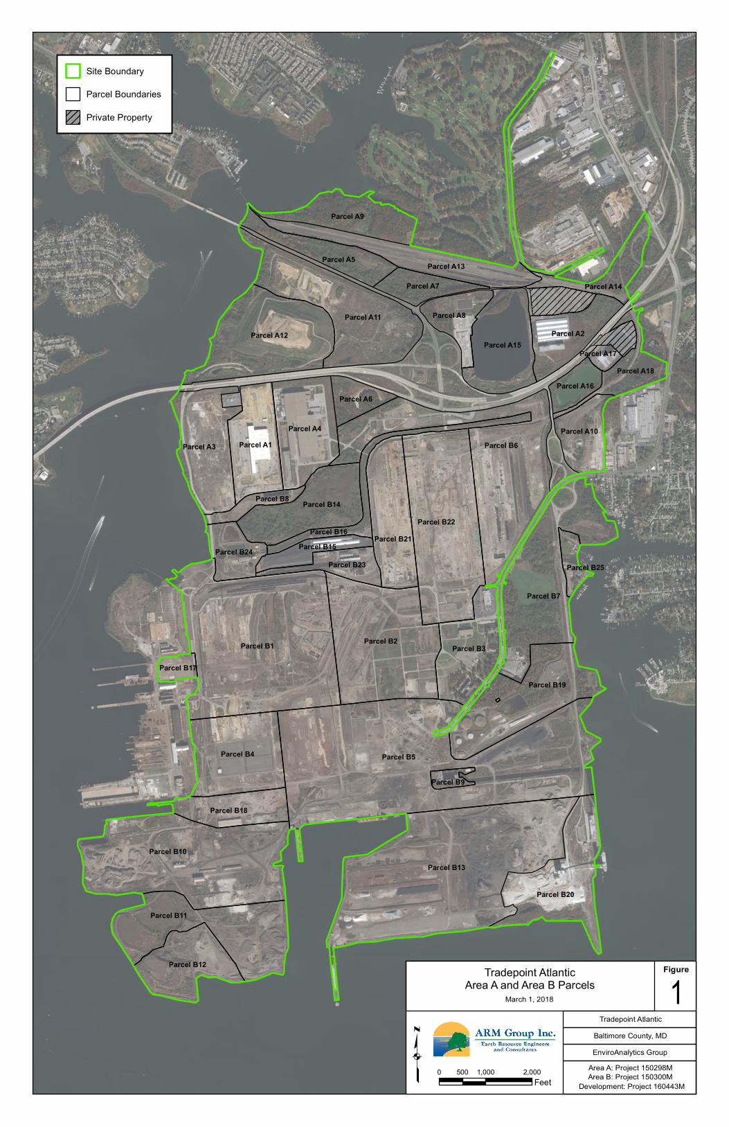
ARM Group Inc. (ARM), on behalf of EnviroAnalytics Group (EAG), has prepared this Pre-Design Investigation (PDI) Work Plan for a portion of the Tradepoint Atlantic property (formerly Sparrows Point Terminal, LLC) that has been designated as Area B: Parcel B14 (the Site). Parcel B14 is comprised of 60.3 acres of the approximately 3,100-acre former steel making facility (Figure 1). The majority of Parcel B14 is occupied by the Humphrey Impoundment, which is approximately 43 acres in size. The Site is bounded to the west by Humphrey Creek Waste Water Treatment Plant (HCWWTP) and Emergency Detention Basin (within Parcel B24), to the north by the Billet Building (within Parcel B8) and the New Cold Mill Complex (NCMC; within Parcel A4), and to the east and south by the Tin Mill Canal (TMC; within Parcel B16). The proposed activities presented in this PDI Work Plan are based on the findings and recommendations from the Phase II Investigation Report for Area B: Parcel B14, Revision 0 dated March 27, 2018, and also communications with the Maryland Department of the Environment (MDE) during a project meeting on June 5, 2018 regarding the conceptual response action plan for Parcel B14.
1.0 BACKGROUND
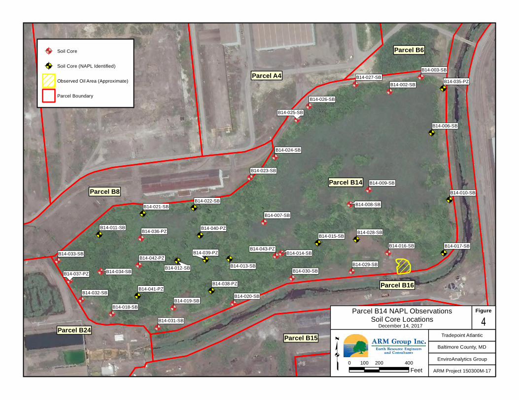
During the Phase II Investigation, 33 soil borings were initially completed across Parcel B14 to provide for the characterization of the materials that had been placed within Humphrey Impoundment during its operation. Several of these soil boring locations exhibited elevated detections of TPH/Oil & Grease and/or had physical evidence of non-aqueous phase liquid (NAPL) in the associated soil cores. Temporary screening piezometers were installed at 14 of these locations (i.e., B14-002-SB, B14-006-SB, B14-007-SB, B14-008-SB, B14-010-SB, B14-011-SB, B14-012-SB, B14-013-SB, B14-015-SB, B14-017-SB, B14-021-SB, B14-022-SB, B14-028-SB, and B14-034-SB) to help delineate the extent and thickness of NAPLs within the
ARM Project 150300M-17 2 June 29, 2018
A R M G r o u p I n c .
impoundment. Based on the detection of NAPLs within many of these piezometers, nine additional temporary screening piezometers (i.e., B14-035-PZ through B14-043-PZ) were subsequently installed at strategic locations to further characterize the extent and thickness of NAPLs across the impoundment. Despite the presence of measurable NAPL in a number of the temporary piezometers, NAPL was not detected in any of the permanent monitoring wells surrounding the impoundment, suggesting that the NAPL is contained within the impoundment. Soil borings locations and inspection logs are included in Appendix A, and piezometer locations with NAPL occurrence and a typical piezometer construction log are included in Appendix B.
Each screening piezometer was gauged for the presence or absence of NAPL with an oil-water interface probe immediately, 48-hours, and at least 30-days after installation. Several of the screening piezometers (based on accessibility) have since been gauged periodically to monitor the accumulation of NAPL within the piezometer casing. The results of the periodic NAPL gauging events are summarized in Appendix C, with the maximum accumulated product thickness in each piezometer summarized in Table 1 of Appendix C.
The screening-level risk assessment (SLRA) completed as part of the Phase II Investigation Report for Parcel B14 did not indicate any unacceptable risks for future Composite Workers. However, based on the currently depressed surface elevation of the impoundment as compared to the perimeter embankment, any future redevelopment of the parcel is currently anticipated to include the placement of fill across the surface of the impoundment to promote surface water runoff, and reduce infiltration.
2.0 PRE-DESIGN INVESTIGATION
2.1 Purpose and Scope
Based on potential concerns associated with the planned fill placement activities, including embankment stability, potential NAPL migration, and future constructability, supplemental pre-design investigation (PDI) activities are warranted to support the completion of final design details and plans for the proposed fill placement. The planned PDI activities are discussed in the following subsections of this Work Plan, and are generally summarized on the attached Figure 2 (Pre-Design Investigation Map) and Table 1 (Pre-Design Investigation Summary).
2.2 Soil Boring Investigation
A supplemental soil boring investigation will be completed to support the characterization of surface and subsurface conditions, and to facilitate the collection of samples for laboratory testing. The soil boring investigation activities will include the use of a drilling rig that is suitable for the site conditions and proposed work, including the ability to drive split-spoon samples for Standard Penetration Testing (SPT) in accordance with ASTM D1586, reach the targeted depths of up to 25 to 30 feet, and create a borehole of large enough diameter to support in-field permeability testing. The assessments to be completed as part of the supplemental soil borings are discussed in the following subsections.

ARM Project 150300M-17 3 June 29, 2018
A R M G r o u p I n c .
2.2.1 Geotechnical Assessment of Embankment
Soil borings will be completed at selected locations along the embankment of the impoundment to support the evaluation of its construction and stability. The approximate boring locations are shown on the attached Figure 2, and consist of the proposed borings B14-001-PDI, B14-005-PDI, B14-007-PDI, and B14-008-PDI. The boring locations were selected to help assess portions of the embankment that have not yet been investigated (a few geotechnical borings were previously completed along the eastern side of the embankment as shown in Appendix D), and where NAPL migration to adjacent areas is considered to be a potential concern. These borings will be extended to a depth of approximately 25 to 30 feet below the existing grade, with the intention of extending through the embankment materials and at least 5 feet into the underling native materials. Continuous split-spoon sampling with SPT testing will be conducted from the ground surface to a depth of 15 feet, and then one more split-spoon and SPT test for every 5 feet thereafter.
During the drilling, SPT blow counts and recoveries will be recorded, and the materials encountered will be logged by the attending scientist or engineer with respect to material type, color, particle size, odors, and any other relevant observations. Representative materials from each boring between a depth of approximately 5 to 15 feet below grade will be set aside and subsequently submitted to a geotechnical testing laboratory for sieve analysis (ASTM D422) and Atterberg limits (ASTM D4318).
The collected information will be used to support the completion of an embankment slope stability analysis for the anticipated impoundment filling activities.
2.2.2 Geotechnical Assessment of Sediments/Sludges
Concurrent with the embankment soil boring investigation program, additional soil borings will completed at selected locations within the impoundment to further characterize the physical properties of the impounded solids to support the evaluation of the embankment stability and potential fluid (i.e., water and NAPL) migration. The approximate boring locations are shown on the attached Figure 2, and consist of the proposed borings B14-002-PDI, B14-003-PDI, B14-004-PDI, and B14-006-PDI. The boring locations were selected to support the embankment stability assessment, the help characterize the materials where NAPL was measured, and based on potential accessibility. These borings will be extended to a depth of approximately 15 to 20 feet below the existing grade, with continuous split-spoon sampling and SPT testing conducted from the ground surface to a depth of 15 feet, and then one more split-spoon and SPT test for every 5 feet thereafter.
During the drilling, SPT blow counts and recoveries will be recorded, and the materials encountered will be logged by the attending scientist or engineer with respect to material type, color, particle size, odors, and any other relevant observations. Representative materials from each boring between a depth of approximately 5 to 15 feet below grade will be set aside and

ARM Project 150300M-17 4 June 29, 2018
A R M G r o u p I n c .
subsequently submitted to a geotechnical testing laboratory for sieve analysis (ASTM D422) and Atterberg limits (ASTM D4318).
The collected information will be used to support the embankment slope stability analysis for the anticipated impoundment filling activities, and to support the evaluation of potential NAPL migration and recoverability within the impoundment.
2.2.3 Field Permeability Testing
To further support the evaluation of potential NAPL migration and recoverability, field permeability testing will be conducted at selected locations to help characterize the permeability of the impounded materials. The permeability test locations will be within or adjacent to the geotechnical boring locations shown on Figure 2 and designated as B14-002-PDI, B14-003-PDI, and B14-006-PDI. The permeability test locations were selected to support the assessment of potential NAPL mobility and recoverability where the greatest NAPL thicknesses were generally detected. At each of the test locations, a 2-inch diameter temporary PCV well will be installed such that the bottom of the well will have 10 to 15 feet of slotted well screen, with solid riser pipe up to the ground surface. The total depth of each well will be approximately 15 to 20 feet, with goal of having 5 to 10 feet of screened interval below the static water level, and 3 to 5 feet of screened interval above the water table. A sand pack will be placed in the annular space around the screened interval and to an elevation of 1 or 2 feet above the screened interval, and the sand pack will be sealed with 1 to 2 feet of hydrated bentonite and then soil fill up to the ground surface. It is anticipated that the permeability tests will generally be conducted as falling head and/or rising head ‘slug’ tests through the addition or removal of water from the wells, and then recording the drop or rise in water level over time until the water level largely recovers to its initial condition. Alternately or in addition to the slug testing, if a constant rate of water addition or withdrawal can be maintained at a relatively constant water level in the well, the associated flow rate and water level will be recorded. Following data collection, the resulting field measurements will then be used to estimate the saturated permeability at each test location using an appropriate analysis method for the field testing conducted and the results obtained (e.g., Bouwer and Rice, Hvorslev, Dagan, and/or other methods as appropriate for partially penetrated unconfined aquifers). The permeability results will be used to support the evaluation of potential dewatering and settlement rates, and the design of a NAPL recovery or control system if warranted.
2.3 NAPL Assessment
Additional testing is planned to support the evaluation of the nature, extent, and potential mobility and recoverability of the observed NAPLs within the impoundment. This additional testing is planned to consist of NAPL bail-down recovery testing, and the collection of NAPL samples for selected physical and chemical property testing as described in the following subsections.
ARM Project 150300M-17 5 June 29, 2018
A R M G r o u p I n c .
2.3.1 NAPL Recovery Testing
NAPL bail testing will be conducted at selected piezometer locations to support the assessment of potential NAPL migration and recoverability. If such studies indicate that NAPL migration beyond the impoundment embankment is a potential concern during or following the planned fill placement activities, some type of NAPL monitoring and recovery/control will likely be proposed as part of the Response Action Plan for the parcel.
For this study, a product bail down test will be completed for each piezometer that has or had a measured NAPL thickness of greater than 0.5 feet. Based on existing information (see Table 1 of Appendix C), 0.5 feet or more of NAPL has been measured at the following piezometer locations: B14-007-PZ, B14-013-PZ, B14-021-PZ, B14-038-PZ, B14-039-PZ, and B14-041-PZ (these piezometer labels are highlighted in yellow on Figure 2). The bail-down testing will be conducted in general accordance with Manual Skimming Field Methods procedure presented in ASTM standard E2856-13 (Estimation of LNAPL Transmissivity). This test consists of the removal of NAPL from the piezometer casing and borehole on a repeated basis, without allowing more than approximately 25% of recovery to occur between product removal events. As a result, the rate of NAPL removal and monitoring is dependent on the NAPL recovery behavior at each test location, and the test can range from a few hours for test locations exhibiting higher NAPL transmissivities to multiple weeks for test locations exhibiting lower NAPL transmissivities. The NAPL recovery volume and gauging data from the test will be used to estimate NAPL transmissivity and recoverability.
Prior to the start of bail down testing, an oil-water interface probe will be used to gauge all 23 NAPL piezometers within Parcel B14. All gauging data, product thickness, and visual product observations (color/viscosity) will be recorded on appropriate field log sheets (see Appendix E). For each piezometer that has more than 0.5 feet of measurable product, the NAPL will initially be removed with a peristaltic pump until all visible free product has been removed or until only trace levels of product remain in the casing; the recovery of water and impacts on the water level will be minimized to the extent practical. The volume of product that is recovered from the piezometer will be recorded on the field log, as will the new depth to water and depth to product. A follow-up gauging measurement will then be completed approximately 10 to 15 minutes later to assess the approximate rate of NAPL recovery, and to support the establishment of an initial time interval that will allow for subsequent gauging of the well before the NAPL has recovered 25% of its initial thickness. The process will be repeated at each of the selected piezometers to establish an initial time interval for the testing. The testing, which will include periodic gauging and NAPL removal, will then be conducted at the selected time intervals, with adjustments to the time intervals made as necessary to help prevent greater than 25% NAPL recovery during the test. The test will be continued until the calculated NAPL recharge rate into the well stabilizes (i.e., when 3 or 4 consecutive discharge rates are within 25% of each other). Following completion of the bail-down test, subsequent gauging events will be conducted to measure the time it takes the NAPL in each piezometer to recover to between 80 and 100% of the initial thickness.
ARM Project 150300M-17 6 June 29, 2018
A R M G r o u p I n c .
Following completion of the tests, the NAPL recovery volume and gauging data from the tests will be used to calculate NAPL transmissivity at each test location per the procedures outlined in the ASTM standard. Final transmissivity values will them be compared to guideline reference values to help make conclusions regarding NAPL recoverability, and the need for any NAPL recovery or control measures as part of the Response Action Plan.
2.3.2 Product Testing
As part of the NAPL assessment, and in conjunction with the bail-down recovery testing, a sample of the NAPL removed from each of the piezometers will be placed into laboratory-supplied bottleware and submitted to Pace Analytical Services, Inc. (PACE) for testing of density and viscosity. The results of this testing will support the evaluation of potential NAPL mobility and recoverability, and potential treatment or disposal requirements for any recovered product. 2.4 Cover Material Study
Based on the current plans for covering the impoundment with fill materials, an evaluation will be conducted to support the identification of one or more appropriate sources of fill for the proposed impoundment cover system. The evaluation will consider the material availability and location, physical and chemical properties, material placement and constructability issues, and other factors as appropriate. Among other potential sources of fill material, this study will evaluate the potential use of dredge materials (e.g., those currently stored at the Coke Point Dredged Material Containment Facility), development excavation spoils, and other possible on-site and off-site fill materials.
2.5 Additional Provisions
All field protocols will be conducted in accordance with the Standard Operating Procedures (SOPs) and requirements given in the property-wide Quality Assurance Project Plan (QAPP). The investigation will also be conducted under the property-wide Health and Safety Plan (HASP). Any NAPL or water removed from the piezometers and temporary wells will be containerized and subsequently disposed of at an appropriate and permitted disposal facility. The selected disposal facility will be approved by the MDE prior to shipment. Any waste generated during the PDI activities will be placed in designated drums and will be managed in bulk with waste from other investigations and will be appropriately characterized prior to disposal.
3.0 CLOSING If you have questions regarding any information covered in this document please feel free to contact ARM Group Inc. at (410) 290-7775.
ARM Project 150300M-17 7 June 29, 2018
A R M G r o u p I n c .
Respectfully Submitted, ARM Group Inc. Leandra M. Glumac Stephen B. Fulton Staff Geologist Sr. Environmental Engineer
Attachments:
Figures Figure 1 – Site Location Map Figure 2 - Parcel B14: Pre-Design Investigation Map Tables Table 1 – Parcel B14: Pre-Design Investigation Summary Appendix A – Soil Boring Location Map and Logs Appendix B – Piezometer Location Map and Typical Construction Log Appendix C – NAPL Gauging Summary Tables Appendix D – Geotechnical Boring Logs Appendix E – Blank Field Sheets for NAPL Recovery Testing

FIGURES
Parcel B12
Parcel B11
Parcel B10Parcel B13
Parcel B20
Parcel B18
Parcel B9
Parcel B4 Parcel B5
Parcel B17Parcel B19
Parcel B3Parcel B2Parcel B1
Parcel B23
Parcel B15
Parcel B25Parcel B24
Parcel B8
Parcel B7
Parcel B14
Parcel B21Parcel B22
Parcel B16
Parcel B6Parcel A10
Parcel A3 Parcel A1Parcel A4
Parcel A6Parcel A16
Parcel A17Parcel A18
Parcel A2
Parcel A8
Parcel A15Parcel A12
Parcel A7
Parcel A11
Parcel A14
Parcel A5
Parcel A9
Site Boundary
Parcel Boundaries
Private Property
Area B: Project 150300M
Tradepoint AtlanticArea A and Area B Parcels
Area A: Project 150298MEnviroAnalytics GroupBaltimore County, MD
March 1, 2018 1Figure
Tradepoint Atlantic
q 0 1,000 2,000500Feet Development: Project 160443M
Parcel A13

@A
@A@A
@A
@A
@A
@A
@A
@A
@A
@A
@A
@A
@A
@A
@A
@A
@A
@A
@A
@A
@A
@A
@?
@?
@?
@?
@?
@?
@?
@?
Parcel B15
Parcel B24
Parcel B8Parcel B14
Parcel B16
Parcel B6
Parcel A1Parcel A4
0'
0'
14'
16'
12'
12'
12'
12'
12'
16'
10'
10'
10'10'
10'
10'
6'
6'
6'
6'
6'
6'
14'
14'
14'
14'
14'
14'
14'
0'
32'
10'
10'
10'10'
12'
2'
2'
2' 2'
2'
2'
2' 2'
2'
2'
6'6'
6'6'
6'
6'
4'
4'
14'
8'8'
8'
8'
8'
8'
8'
8'
8'
8'
8'
2'
0'
0'
0'
0'24'
12'
10'
10'
10'
10'
10'10'
10'
10'
10'
10'
10'
10'
10'10'
10'
10'
10'
10'
10'
10'
10'
10'
10' 10'
10'
8'
8'
8' 8'
8'
8'
10'
6'
6'
6'
6'
4'
4'
4'
8'
8'
10'
10'
10'
12'14'
12'
10'
12'12'
12'
12'
12'
12'
12'
12'
6'
6'
6'
6'
4'
4'
10'
8'8'
8'8'
8'
8'
8'
8'
8'
10'
14'
8'
10'
10'
10'
10'
10'
6'
12'10'
16'
10'
12' 12'
12'
12'
12'
18'
18'
16'
16'16'
20'
20' 20'22'
14'
14'
14'
10'
18'
4'
18'
12'
14'
14'
22'
14'
30'
20'
18'
10'
12'
28'
10'
12'
8'
8'
12'
12'
16'
10'
14'
12'
10'
14'
8'
10'
16'
14'
8'
12'
20'
12'
18'
12'
10'
14'
6'
18'26'
28'
8'
14'
16'
12'
14'
18'
26'
16'
4'
24'
8'
16'
14'
22'
6' 14'
8'
4'
12'
12'
0'
12'
2'
16'
4'
6'
8'
10'
6'14'
4'
8'
4'
18'
18'
14' 14'
16' 16'
10'
10'
2'
2'
2'
4'
4'
4'
4'
4'4'
4'
4'
14'
14'
14'
8'
8'
8'
B14-011-PZ
B14-012-PZB14-013-PZ
B14-015-PZ
B14-008-PZ
B14-017-PZ
B14-010-PZ
B14-002-PZ
B14-006-PZ
B14-021-PZ
B14-028-PZ
B14-022-PZ
B14-034-PZ
B14-036-PZ
B14-042-PZ
B14-041-PZ
B14-040-PZ
B14-039-PZ
B14-038-PZ
B14-035-PZ
B14-037-PZ B14-043-PZ
B14-007-PZ
HI02-PZM006
HI04-PZM006
HI07-PZM005
TM02-PZM009
TM04-PZM006
TM06-PZM008
TM08-PZM007
Well 2
Tradepoint AtlanticBaltimore County, MD
EnviroAnalytics GroupARM Project 150300M-17
Parcel B14 Pre-Design Investigation Map 2
Figure
June 13, 2018
0 100 20050Feetq
@? Existing Well
@A clean 30 day
@A measureable
@A trace
Existing Elevations in ft(2 ft Interval)
Proposed Soil Boring Location (approx.)
Parcel Boundary
Potential Limited AccessAreas (ponded water,mud, etc.)
Notes: Boring locations subject to change. Orange highlightingdenotes piezometers planned for LNAPL recovery testing.

TABLES
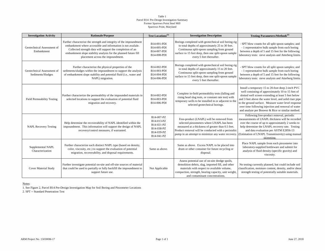
Table 1Parcel B14: Pre-Design Investigation Summary
Former Sparrows Point Steel MillSparrows Point, Maryland
ARM Project No. 150300M-17 Page 1 of 1 June 27, 2018
Investigation Activity Rationale/Purpose Test Locations(1) Investigation Description Testing Parameters/Methods(2)
Geotechnical Assessment of Embankment
Further characterize the strength and integrity of the impoundment embankment where accessible and information is not availale.
Collected strength data will support the completion of an embankment slope stability analysis for the planned future fill
placement across the impoundment.
B14-001-PDIB14-005-PDIB14-007-PDIB14-008-PDI
Borings completed with geotechnical soil boring rig to total depths of approximately 25 to 30 feet. Continuous split-spoon sampling from ground
surface to 15 feet deep, then one split-spoon sample every 5 feet thereafter.
- SPT blow counts for all split spoon samples; and- 1 representative bulk sample from each boring
between a depth of 5 and 15 feet for the following laboratory tests: sieve analysis and Atterberg limits.
Geotechnical Assessment of Sediments/Sludges
Further characterize the physical properties of the sediments/sludges within the impoundment to support the analysis of embankment slope stability and potential fluid (i.e., water and
NAPL) migration.
B14-002-PDIB14-003-PDIB14-004-PDIB14-006-PDI
Borings completed with geotechnical soil boring rig to total depths of approximately 15 to 20 feet. Continuous split-spoon sampling from ground
surface to 15 feet deep, then one split-spoon sample every 5 feet thereafter.
- SPT blow counts for all split spoon samples; and- 1 representative bulk sample from each boring
between a depth of 5 and 15 feet for the following laboratory tests: sieve analysis and Atterberg limits.
Field Permeability TestingFurther characterize the permeability of the impounded materials in
selected locations to support the evaluation of potential fluid migration and recovery.
B14-002-PDIB14-003-PDIB14-006-PDI
Complete in-field permeability tests (falling and rising head slug tests, or constant rate test) with
temporary wells to be installed in or adjacent to the selected geotechnical borings.
Install a temporary 15 to 20-foot deep 2-inch PVC well consisting of approximately 10 to 15 feet of slotted well screen extending at least 5 feet below
and 3 feet above the water level, and solid riser pipe to the ground surface. Measure water level response over time following injection and removal of water and analyze per Bouwer & Rice or similar method.
NAPL Recovery Testing Help determine the recoverability of NAPL identified within the
impoundment. This information will support the design of NAPL recovery/control measures, if warranted.
B14-007-PZB14-013-PZB14-021-PZB14-038-PZB14-039-PZB14-041-PZ
Free-product (LNAPL) will be removed from selected piezometers where LNAPL has been
measured at a thickness of greater than 0.5 feet. Product removal will be conducted with a peristaltic pump in an attempt to minimize any water recovery.
Following free-product removal, periodic measurements of LNAPL thickness will be recorded over the course of up to approximately 2 weeks to help determine the LNAPL recovery rate. Testing
and data evaluation per ASTM E2856-13 (Estimation of LNAPL Transmissivity) using manual
skimming.
Supplemental NAPL Characterization
Further characterize each distinct NAPL type (based on density, color, viscosity, etc.) to support the evaluation of potential
migration, recoverability, and disposal requirements.Same as above.
Same as above. Excess NAPL to be placed into drum or other container for future recycling or
disposal.
Place NAPL sample from each piezometer into laboratory-supplied bottleware and submit for analysis of fluid density (specific gravity) and
viscosity.
Cover Material StudyFurther investigate potential on-site and off-site sources of material that could be used to partially or fully backfill the impoundment to
support future use.Not Applicable
Assess potential use of on-site dredge spoils, demolition debris, slag, imported fill, and other
materials with respect to available volume, compaction, strength, bearing capacity, unit weight,
and contaminant concentrations.
No testing currently planned, but could include soil classification, moisture content, density, and/or shear
strength testing of potentially suitable materials.
Notes:1. See Figure 2, Parcel B14 Pre-Design Investigation Map for Soil Boring and Piezometer Locations2. SPT = Standard Penetration Test
APPENDIX A
Soil Boring Location Map and Logs
@A
@A
@A
@A
@A
@A
@A
@A
@A
@A
@A@A
@A
@A
@A @A@A
@A
@A
@A
@A
@A @A
@A
@A
@A
@A
@A
@A
@A
@A
@A
@A
@A
@A
@A
@A
@A
@A
@A
@A
Parcel A1
Parcel A4
Parcel B23
Parcel B15Parcel B24
Parcel B8Parcel B14
Parcel B16
Parcel B6
B14-034-SB
B14-036-PZ
B14-042-PZ
B14-041-PZ
B14-040-PZ
B14-039-PZ
B14-038-PZ
B14-035-PZ
B14-037-PZ
B14-043-PZ
B14-018-SBB14-019-SB
B14-011-SB
B14-020-SB
B14-012-SB B14-013-SB
B14-014-SB
B14-007-SB
B14-015-SB
B14-008-SB
B14-009-SB
B14-016-SB B14-017-SB
B14-010-SB
B14-002-SB
B14-006-SB
B14-003-SB
B14-026-SB
B14-024-SB
B14-023-SB
B14-021-SB
B14-029-SB
B14-025-SB
B14-028-SB
B14-027-SB
B14-033-SB
B14-032-SB
B14-031-SB
B14-030-SB
B14-022-SB
@A Soil Core
@A Soil Core (NAPL Identified)
Observed Oil Area (Approximate)
Parcel Boundary
Tradepoint Atlantic
Baltimore County, MD
EnviroAnalytics Group
ARM Project 150300M-17
Parcel B14 NAPL ObservationsSoil Core Locations 4
Figure
December 14, 2017
0 200 400100Feetq

Parcel A1
Parcel A4
Parcel B23
Parcel B15Parcel B24
Parcel B8
Parcel B16
Parcel B6@A Soil Core
@A Soil Core (NAPL Identified)
Observed Oil Area (Approximate)
Parcel Boundary
Tradepoint Atlantic
Baltimore County, MD
EnviroAnalytics Group
ARM Project 150300M-17
Parcel B14 NAPL ObservationsSoil Core Locations 5
Figure
December 14, 2017
0 200 400100Feetq
@A
@A
@A
@A
@A
@A
@A
@A
@A
@A
@A@A
@A
@A
@A @A@A
@A
@A
@A
@A
@A @A
@A
@A
@A
@A
@A
@A
@A
@A
@A
@A
@A
@A
@A
@A
@A
@A
@A
@A B14-034-SB
B14-036-PZ
B14-042-PZ
B14-041-PZ
B14-040-PZ
B14-039-PZ
B14-038-PZ
B14-035-PZ
B14-037-PZ
B14-043-PZ
B14-018-SBB14-019-SB
B14-011-SB
B14-020-SB
B14-012-SB B14-013-SB
B14-014-SB
B14-007-SBB14-008-SB
B14-009-SB
B14-016-SB B14-017-SB
B14-010-SB
B14-002-SB
B14-006-SB
B14-003-SB
B14-026-SB
B14-024-SB
B14-023-SB
B14-021-SB
B14-029-SB
B14-025-SB
B14-028-SB
B14-027-SB
B14-033-SB
B14-032-SB
B14-031-SB
B14-030-SB
B14-022-SB
B14-015-SB
Parcel B14
Cross-A
Cross-B
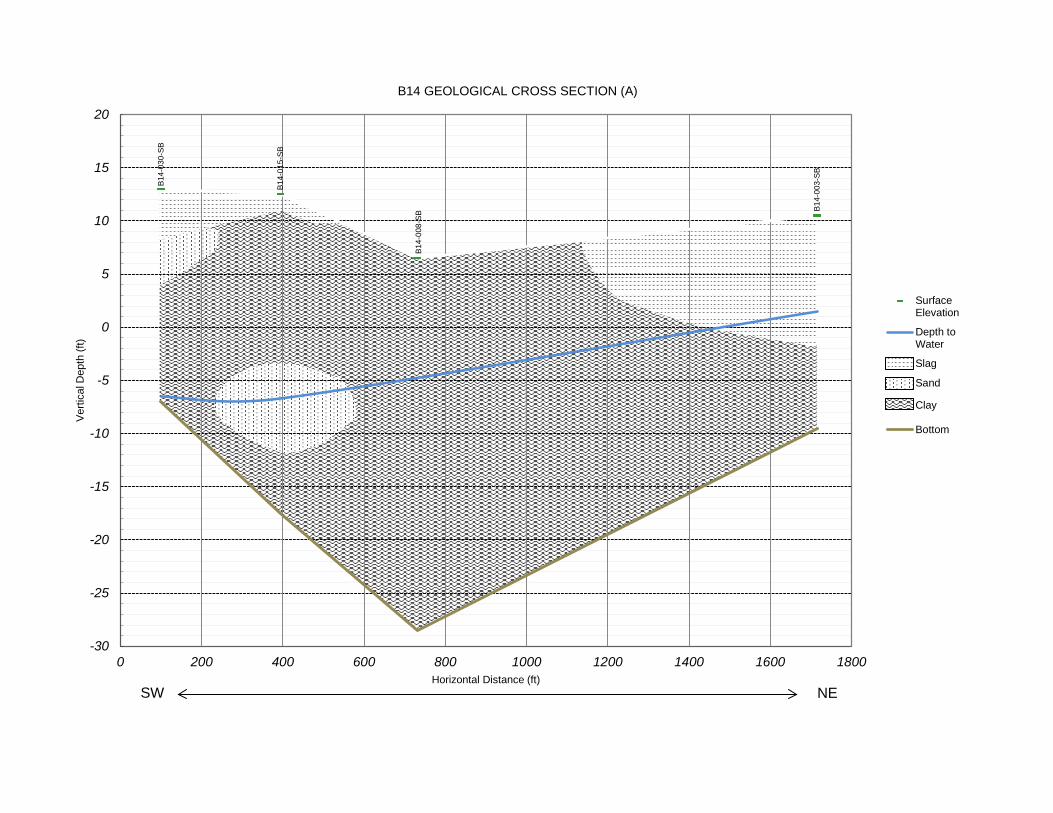
B14-0
30-S
B
B14-0
15-S
B
B14-0
08-S
B B14-0
03-S
B
-30
-25
-20
-15
-10
-5
0
5
10
15
20
0 200 400 600 800 1000 1200 1400 1600 1800
Vertic
al De
pth (ft
)
Horizontal Distance (ft)
B14 GEOLOGICAL CROSS SECTION (A)
SurfaceElevationDepth toWaterSlagSandClayBottom
SW NE

B14-0
37-S
B
B14-0
34-S
B
B14-0
12-S
B
B14-0
39-S
B
B14-0
13-S
B
B14-0
43-S
B
B14-0
15-S
B
B14-0
28-S
B
B14-0
10-S
B
-20
-15
-10
-5
0
5
10
15
20
0 500 1000 1500 2000 2500
Vertic
al De
pth (ft
)
Horizontal Distance (ft)
B14 GEOLOGICAL CROSS SECTION (B)
SurfaceElevationDepth toWaterSlag
ClaySand
Bottom
W E
12-14
-2017
P:\E
nviro
Analy
tics G
roup\1
5030
0M EA
G_Sp
arrow
s Poin
t Area
B\Do
cume
nts\Pa
rcel B
14\Bo
ring L
ogs\2
_bor\
B14-0
02-S
B.bor
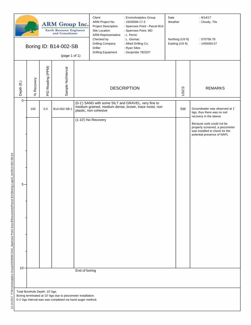
Boring ID: B14-002-SB(page 1 of 1)
Total Borehole Depth: 10' bgs.Boring terminated at 10' bgs due to piezometer installation.0-1' bgs interval was was completed via hand auger method.
Client : EnviroAnalytics GroupARM Project No. : 150300M-17-3Project Description : Sparrows Point - Parcel B14Site Location : Sparrows Point, MDARM Representative : L. PerrinChecked by : L. GlumacDrilling Company : Allied Drilling Co.Driller : Ryan SitesDrilling Equipment : Geoprobe 7822DT
Date : 9/14/17Weather : Cloudy, 70s
Northing (US ft) : 570756.78Easting (US ft) : 1459350.57
Depth
(ft.)
0
5
10
% Re
cove
ry
100
PID R
eadin
g (PP
M)
0.0
Samp
le No
/Inter
val
B14-002-SB-1
DESCRIPTION
(0-1') SAND with some SILT and GRAVEL, very fine to medium grained, medium dense, brown, trace moist, non plastic, non cohesive
(1-10') No Recovery
End of boring
USCS
SW
REMARKS
Groundwater was observed at 1' bgs, thus there was no soil recovery in the sleeve
Because soils could not be properly screened, a piezometer was installed to check for the potential presence of NAPL
12-05
-2017
P:\E
nviro
Analy
tics G
roup\1
5030
0M EA
G_Sp
arrow
s Poin
t Area
B\Do
cume
nts\Pa
rcel B
14\Bo
ring L
ogs\2
_bor\
B14-0
03-S
B.bor
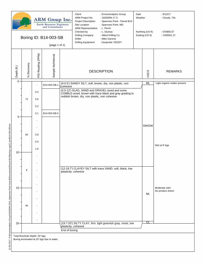
Boring ID: B14-003-SB(page 1 of 1)
Total Borehole Depth: 20' bgs.Boring terminated at 20' bgs due to water.
Client : EnviroAnalytics GroupARM Project No. : 150300M-17-3Project Description : Sparrows Point - Parcel B14Site Location : Sparrows Point, MDARM Representative : L. PerrinChecked by : L. GlumacDrilling Company : Allied Drilling Co.Driller : Mike GarvineDrilling Equipment : Geoprobe 7822DT
Date : 9/13/17Weather : Cloudy, 70s
Northing (US ft) : 570855.57Easting (US ft) : 1459561.37
Depth
(ft.)
0
5
10
15
20
% Re
cove
ry
72
60
8
40
PID R
eadin
g (PP
M)
-
0.4
0.6
0.2
0.1
-
-
0.8
0.5
1.6
-
-
-
-
-
-
-
-
-
-
Samp
le No
/Inter
val
B14-003-SB-1
B14-003-SB-5
DESCRIPTION
(0-0.5') SANDY SILT, soft, brown, dry, non plastic, non cohesive(0.5-12') SLAG, SAND and GRAVEL-sized and some COBBLE-sized, brown with trace black and gray grading to reddish brown, dry, non plastic, non cohesive
(12-19.7') CLAYEY SILT with trace SAND, soft, black, low plasticity, cohesive
(19.7-20') SILTY CLAY, firm, light greenish gray, moist, low plasticity, cohesiveEnd of boring
USCS
ML
SW/GW
ML
CL
REMARKS
Light organic matter present
Moderate odorNo product sheen
Wet at 9' bgs

12-05
-2017
P:\E
nviro
Analy
tics G
roup\1
5030
0M EA
G_Sp
arrow
s Poin
t Area
B\Do
cume
nts\Pa
rcel B
14\Bo
ring L
ogs\2
_bor\
B14-0
06-S
B.bor
Boring ID: B14-006-SB(page 1 of 1)
Total Borehole Depth: 10' bgs.Boring terminated at 10' bgs due to water and piezometer installation.
Client : EnviroAnalytics GroupARM Project No. : 150300M-17-3Project Description : Sparrows Point - Parcel B14Site Location : Sparrows Point, MDARM Representative : L. PerrinChecked by : L. GlumacDrilling Company : Allied Drilling Co.Driller : Mike GarvineDrilling Equipment : Geoprobe 7822DT
Date : 9/13/17Weather : Rainy, 70s
Northing (US ft) : 570478.47Easting (US ft) : 1459634.31
Depth
(ft.)
0
5
10
% Re
cove
ry
30
50
PID R
eadin
g (PP
M)
-
-
-
1.0
0.1
-
-
0.1
0.4
2.5
Samp
le No
/Inter
val
B14-006-SB-1
B14-006-SB-5
DESCRIPTION
(0-2.5') CLAYEY SAND, medium dense, reddish brown, moist, non plastic, non cohesive
(2.5-6') CLAYEY SILT with trace SAND, very soft to soft, black and brown, very moist, low plasticity, cohesive
(6-9.5') GRAVEL with SILT and SAND, loose, black, wet, non plastic, non cohesive
(9.5-10') CLAY, soft, grayish green with black streaks, very moist, low plasticity, cohesiveEnd of boring
USCS
SC
ML
GW-GM
CL
REMARKS
Moderate organic matter present
Light product sheen from 7.5-9.5' bgs
Wet at 7.5' bgs
12-05
-2017
P:\E
nviro
Analy
tics G
roup\1
5030
0M EA
G_Sp
arrow
s Poin
t Area
B\Do
cume
nts\Pa
rcel B
14\Bo
ring L
ogs\2
_bor\
B14-0
07-S
B.bor
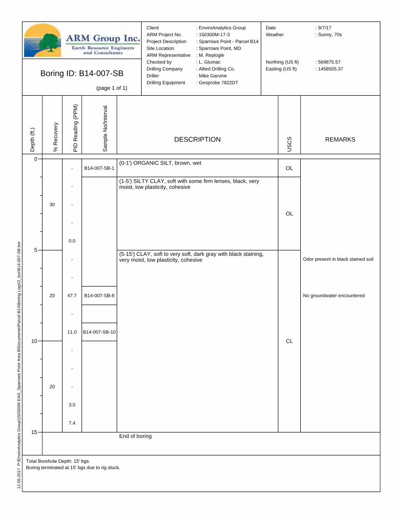
Boring ID: B14-007-SB(page 1 of 1)
Total Borehole Depth: 15' bgs.Boring terminated at 15' bgs due to rig stuck.
Client : EnviroAnalytics GroupARM Project No. : 150300M-17-3Project Description : Sparrows Point - Parcel B14Site Location : Sparrows Point, MDARM Representative : M. ReplogleChecked by : L. GlumacDrilling Company : Allied Drilling Co.Driller : Mike GarvineDrilling Equipment : Geoprobe 7822DT
Date : 9/7/17Weather : Sunny, 70s
Northing (US ft) : 569875.57Easting (US ft) : 1458505.37
Depth
(ft.)
0
5
10
15
% Re
cove
ry
30
20
20
PID R
eadin
g (PP
M)
-
-
-
-
0.0
-
-
47.7
-
11.0
-
-
-
3.0
7.4
Samp
le No
/Inter
val
B14-007-SB-1
B14-007-SB-8
B14-007-SB-10
DESCRIPTION
(0-1') ORGANIC SILT, brown, wet
(1-5') SILTY CLAY, soft with some firm lenses, black, very moist, low plasticity, cohesive
(5-15') CLAY, soft to very soft, dark gray with black staining, very moist, low plasticity, cohesive
End of boring
USCS
OL
OL
CL
REMARKS
Odor present in black stained soil
No groundwater encountered
12-05
-2017
P:\E
nviro
Analy
tics G
roup\1
5030
0M EA
G_Sp
arrow
s Poin
t Area
B\Do
cume
nts\Pa
rcel B
14\Bo
ring L
ogs\2
_bor\
B14-0
08-S
B.bor
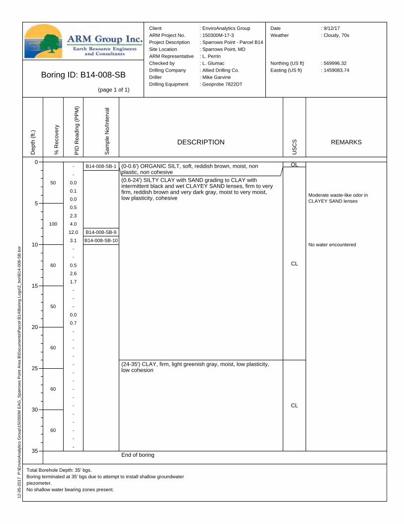
Boring ID: B14-008-SB(page 1 of 1)
Total Borehole Depth: 35' bgs.Boring terminated at 35' bgs due to attempt to install shallow groundwater piezometer.No shallow water bearing zones present.
Client : EnviroAnalytics GroupARM Project No. : 150300M-17-3Project Description : Sparrows Point - Parcel B14Site Location : Sparrows Point, MDARM Representative : L. PerrinChecked by : L. GlumacDrilling Company : Allied Drilling Co.Driller : Mike GarvineDrilling Equipment : Geoprobe 7822DT
Date : 9/12/17Weather : Cloudy, 70s
Northing (US ft) : 569996.32Easting (US ft) : 1459083.74
Depth
(ft.)
0
5
10
15
20
25
30
35
% Re
cove
ry
50
100
60
50
60
60
60
PID R
eadin
g (PP
M)
--
0.00.10.00.52.34.0
12.03.1--
0.52.61.7---
0.00.7---------------
Samp
le No
/Inter
val
B14-008-SB-1
B14-008-SB-9B14-008-SB-10
DESCRIPTION
(0-0.6') ORGANIC SILT, soft, reddish brown, moist, non plastic, non cohesive(0.6-24') SILTY CLAY with SAND grading to CLAY with intermittent black and wet CLAYEY SAND lenses, firm to very firm, reddish brown and very dark gray, moist to very moist, low plasticity, cohesive
(24-35') CLAY, firm, light greenish gray, moist, low plasticity, low cohesion
End of boring
USCS
OL
CL
CL
REMARKS
No water encountered
Moderate waste-like odor in CLAYEY SAND lenses
12-05
-2017
P:\E
nviro
Analy
tics G
roup\1
5030
0M EA
G_Sp
arrow
s Poin
t Area
B\Do
cume
nts\Pa
rcel B
14\Bo
ring L
ogs\2
_bor\
B14-0
09-S
B.bor
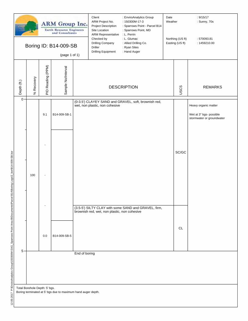
Boring ID: B14-009-SB(page 1 of 1)
Total Borehole Depth: 5' bgs.Boring terminated at 5' bgs due to maximum hand auger depth.
Client : EnviroAnalytics GroupARM Project No. : 150300M-17-3Project Description : Sparrows Point - Parcel B14Site Location : Sparrows Point, MDARM Representative : L. PerrinChecked by : L. GlumacDrilling Company : Allied Drilling Co.Driller : Ryan SitesDrilling Equipment : Hand Auger
Date : 9/15/17Weather : Sunny, 70s
Northing (US ft) : 570093.81Easting (US ft) : 1459210.00
Depth
(ft.)
0
5
% Re
cove
ry
100
PID R
eadin
g (PP
M)
9.1
-
-
-
0.0
Samp
le No
/Inter
val
B14-009-SB-1
B14-009-SB-5
DESCRIPTION
(0-3.5') CLAYEY SAND and GRAVEL, soft, brownish red, wet, non plastic, non cohesive
(3.5-5') SILTY CLAY with some SAND and GRAVEL, firm, brownish red, wet, non plastic, non cohesive
End of boring
USCS
SC/GC
CL
REMARKS
Heavy organic matter
Wet at 3" bgs- possible stormwater or groundwater

12-05
-2017
P:\E
nviro
Analy
tics G
roup\1
5030
0M EA
G_Sp
arrow
s Poin
t Area
B\Do
cume
nts\Pa
rcel B
14\Bo
ring L
ogs\2
_bor\
B14-0
10-S
B.bor
Boring ID: B14-010-SB(page 1 of 1)
Total Borehole Depth: 22' bgs.Boring terminated at 22' bgs due to water and piezometer installation.
Client : EnviroAnalytics GroupARM Project No. : 150300M-17-3Project Description : Sparrows Point - Parcel B14Site Location : Sparrows Point, MDARM Representative : L. PerrinChecked by : L. GlumacDrilling Company : Allied Drilling Co.Driller : Ryan SitesDrilling Equipment : Geoprobe 7822DT
Date : 9/13/17Weather : Rainy, 70s
Northing (US ft) : 570027.32Easting (US ft) : 1459753.99
Depth
(ft.)
0
5
10
15
20
% Re
cove
ry
68
60
40
50
0
PID R
eadin
g (PP
M)
-
1.0
1.0
4.1
0.6
-
0.9
28.0
1.3
-
-
-
-
-
-
-
-
-
-
-
Samp
le No
/Inter
val
B14-010-SB-1
B14-010-SB-5
DESCRIPTION
(0-1.5') SILTY SAND, loose, brown, dry, non plastic, non cohesive
(1.5-5.5') SLAG GRAVEL, fine to coarse, with SAND, medium dense to dense, gray and grayish brown, dry, non plasticity, non cohesive; with CLAY from 3.5-4' bgs
(5.5-9.5') BRICK and SLAG GRAVEL with SILT, reddish brown, dry then wet at 7' bgs, non plastic, non cohesive
(9.5-20') SLAG GRAVEL with some SILT, black, wet, non plastic, non cohesive
(20-22') No recovery
End of boring
USCS
SM
GW
GW-GM
GP
REMARKS
Trace organic matter present
Trace large metallic SLAG
Moderate sheen, no odor (9.5-20' bgs)
Wet at 7' bgs
12-05
-2017
P:\E
nviro
Analy
tics G
roup\1
5030
0M EA
G_Sp
arrow
s Poin
t Area
B\Do
cume
nts\Pa
rcel B
14\Bo
ring L
ogs\2
_bor\
B14-0
11-S
B.bor
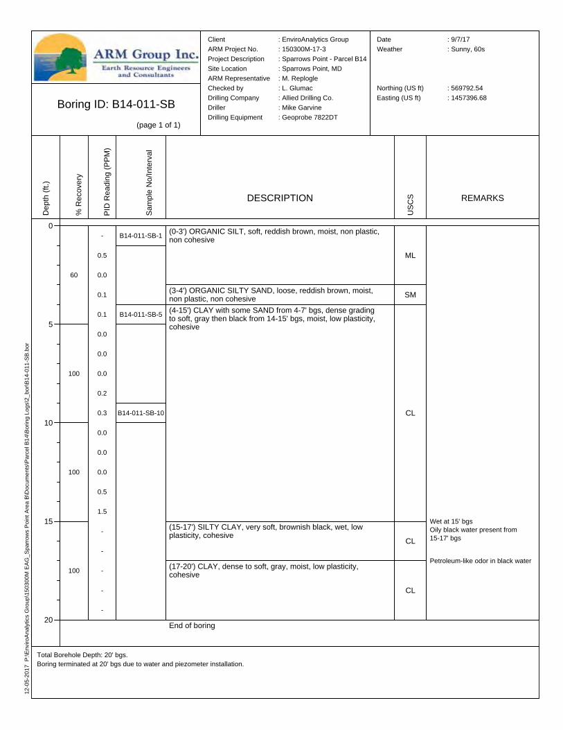
Boring ID: B14-011-SB(page 1 of 1)
Total Borehole Depth: 20' bgs.Boring terminated at 20' bgs due to water and piezometer installation.
Client : EnviroAnalytics GroupARM Project No. : 150300M-17-3Project Description : Sparrows Point - Parcel B14Site Location : Sparrows Point, MDARM Representative : M. ReplogleChecked by : L. GlumacDrilling Company : Allied Drilling Co.Driller : Mike GarvineDrilling Equipment : Geoprobe 7822DT
Date : 9/7/17Weather : Sunny, 60s
Northing (US ft) : 569792.54Easting (US ft) : 1457396.68
Depth
(ft.)
0
5
10
15
20
% Re
cove
ry
60
100
100
100
PID R
eadin
g (PP
M)
-
0.5
0.0
0.1
0.1
0.0
0.0
0.0
0.2
0.3
0.0
0.0
0.0
0.5
1.5
-
-
-
-
-
Samp
le No
/Inter
val
B14-011-SB-1
B14-011-SB-5
B14-011-SB-10
DESCRIPTION
(0-3') ORGANIC SILT, soft, reddish brown, moist, non plastic, non cohesive
(3-4') ORGANIC SILTY SAND, loose, reddish brown, moist, non plastic, non cohesive(4-15') CLAY with some SAND from 4-7' bgs, dense grading to soft, gray then black from 14-15' bgs, moist, low plasticity, cohesive
(15-17') SILTY CLAY, very soft, brownish black, wet, low plasticity, cohesive
(17-20') CLAY, dense to soft, gray, moist, low plasticity, cohesive
End of boring
USCS
ML
SM
CL
CL
CL
REMARKS
Petroleum-like odor in black water
Wet at 15' bgsOily black water present from 15-17' bgs

12-05
-2017
P:\E
nviro
Analy
tics G
roup\1
5030
0M EA
G_Sp
arrow
s Poin
t Area
B\Do
cume
nts\Pa
rcel B
14\Bo
ring L
ogs\2
_bor\
B14-0
12-S
B.bor
Boring ID: B14-012-SB(page 1 of 1)
Total Borehole Depth: 20' bgs.Boring terminated at 20' bgs due to water and piezometer installation.
Client : EnviroAnalytics GroupARM Project No. : 150300M-17-3Project Description : Sparrows Point - Parcel B14Site Location : Sparrows Point, MDARM Representative : L. PerrinChecked by : L. GlumacDrilling Company : Allied Drilling Co.Driller : Mike GarvineDrilling Equipment : Geoprobe 7822DT
Date : 9/6/17Weather : Rainy, 60s
Northing (US ft) : 569615.62Easting (US ft) : 1457923.32
Depth
(ft.)
0
5
10
15
20
% Re
cove
ry
82
80
60
20
PID R
eadin
g (PP
M)
-
0.0
0.0
0.0
0.0
-
0.2
1.8
53.6
215.2
-
-
-
22.8
14.2
-
-
-
-
25.5
Samp
le No
/Inter
val
B14-012-SB-1
B14-012-SB-9
B14-012-SB-10
DESCRIPTION
(0-1.1') ORGANIC SILT, soft, dark brown, moist to dry, non plastic, non cohesive(1.1-2') SANDY CLAY, dense, dark brownish red, dry, low plasticity, cohesive(2-2.7') SAND, fine grained, with CLAY, dense, dark reddish brown, dry, non plastic, non cohesive(2.7-9') SILTY CLAY, dense grading to soft, brownish red with trace dark grayish brown, dry then very moist at 6' bgs, low plasticity, cohesive
(9-10') SILTY CLAY, firm, dark brownish gray, very moist, low plasticity, cohesive
(11.5-17') SAND, fine to medium grained, medium dense, gray, wet, non plastic, non cohesive
(17-20') SILTY CLAY, soft, black, very moist, low plasticity, cohesive
End of boring
USCS
OL
CLSP
CL
CL
SW
CL
REMARKS
Sludge-like odor 8-15' bgs
Wet at 11.5' bgs

01-03
-2018
P:\E
nviro
Analy
tics G
roup\1
5030
0M EA
G_Sp
arrow
s Poin
t Area
B\Do
cume
nts\Pa
rcel B
14\Bo
ring L
ogs\2
_bor\
B14-0
13-S
B.bor
Boring ID: B14-013-SB(page 1 of 1)
Total Borehole Depth: 20' bgs.Boring terminated at 20' bgs due to water.
Client : EnviroAnalytics GroupARM Project No. : 150300M-17-3Project Description : Sparrows Point - Parcel B14Site Location : Sparrows Point, MDARM Representative : M. ReplogleChecked by : L. GlumacDrilling Company : Allied Drilling Co.Driller : Mike GarvineDrilling Equipment : Geoprobe 7822DT
Date : 9/7/17Weather : Sunny, 60s
Northing (US ft) : 569629.46Easting (US ft) : 1458273.70
Depth
(ft.)
0
5
10
15
20
% Re
cove
ry
70
100
60
70
PID R
eadin
g (PP
M)
-
1.0
0.2
0.3
0.0
1.5
2.1
10.6
28.7
18.8
-
-
3.3
2.3
0.8
-
-
1.9
1.7
2.0
Samp
le No
/Inter
val
B14-013-SB-1
B14-013-SB-9
B14-013-SB-10
DESCRIPTION
(0-1') ORGANIC SILT, loose, brown, dry, non plastic, non cohesive(1-3') CLAYEY SILT with GRAVEL, firm, dark reddish grayish brown, moist, low plasticity
(3-8') SILTY CLAY with trace GRAVEL, firm to soft, dark reddish grayish brown, moist to very moist, low plasticity, cohesive
(8-10') CLAY, medium firm, dark gray, moist, medium plasticity, cohesive
(10-16.5') CLAY with some SAND, medium soft, dark grayish black, very moist, medium plasticty, cohesive
(16.5-17') SILTY SAND, loose, black, wet, non plastic, non cohesive(16.8-18') CLAY, soft, black, wet, low plasticity, cohesive(18-18.5') SAND, loose, black, wet, non plastic, non cohesive(18.5-20') CLAY, soft, black, wet, medium plasticity, cohesiveEnd of boring
USCS
OL
ML
CL
CL
CL
SMCLSP
CL
REMARKS
Clay breaks on flat planes into cubes
Wet at 16.' bgsBlack oily water present in black water
Petroleum-like odor in black water
12-05
-2017
P:\E
nviro
Analy
tics G
roup\1
5030
0M EA
G_Sp
arrow
s Poin
t Area
B\Do
cume
nts\Pa
rcel B
14\Bo
ring L
ogs\2
_bor\
B14-0
14-S
B.bor
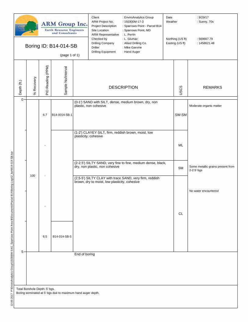
Boring ID: B14-014-SB(page 1 of 1)
Total Borehole Depth: 5' bgs.Boring terminated at 5' bgs due to maximum hand auger depth.
Client : EnviroAnalytics GroupARM Project No. : 150300M-17-3Project Description : Sparrows Point - Parcel B14Site Location : Sparrows Point, MDARM Representative : L. PerrinChecked by : L. GlumacDrilling Company : Allied Drilling Co.Driller : Mike GarvineDrilling Equipment : Hand Auger
Date : 9/29/17Weather : Sunny, 70s
Northing (US ft) : 569667.79Easting (US ft) : 1458621.48
Depth
(ft.)
0
5
% Re
cove
ry
100
PID R
eadin
g (PP
M)
6.7
-
-
-
6.5
Samp
le No
/Inter
val
B14-0014-SB-1
B14-014-SB-5
DESCRIPTION
(0-1') SAND with SILT, dense, medium brown, dry, non plastic, non cohesive
(1-2') CLAYEY SILT, firm, reddish brown, moist, low plasticity, cohesive
(2-2.5') SILTY SAND, very fine to fine, medium dense, black, dry, non plastic, non cohesive
(2.5-5') SILTY CLAY with trace SAND, very firm, reddish brown, dry to moist, low plasticity, cohesive
End of boring
USCS
SW-SM
ML
SM
CL
REMARKS
Moderate organic matter
Some metallic grains present from 2-2.5' bgs
No water encountered
01-03
-2018
P:\E
nviro
Analy
tics G
roup\1
5030
0M EA
G_Sp
arrow
s Poin
t Area
B\Do
cume
nts\Pa
rcel B
14\Bo
ring L
ogs\2
_bor\
B14-0
15-S
B.bor
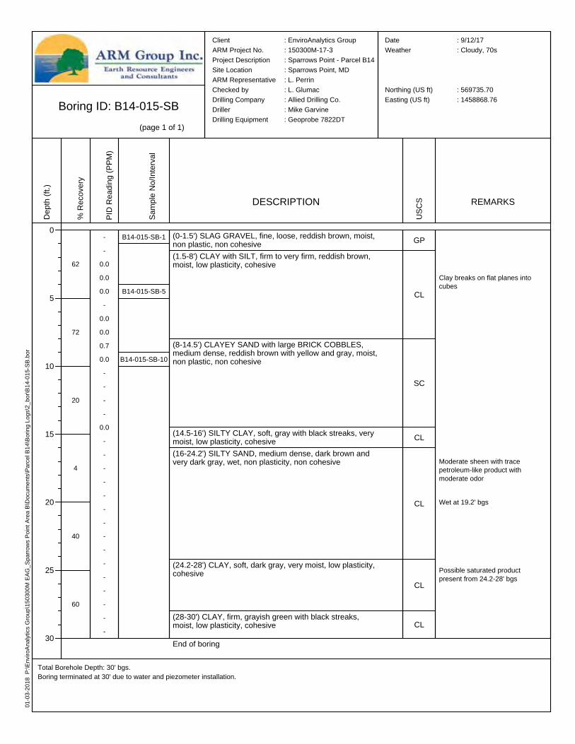
Boring ID: B14-015-SB(page 1 of 1)
Total Borehole Depth: 30' bgs.Boring terminated at 30' due to water and piezometer installation.
Client : EnviroAnalytics GroupARM Project No. : 150300M-17-3Project Description : Sparrows Point - Parcel B14Site Location : Sparrows Point, MDARM Representative : L. PerrinChecked by : L. GlumacDrilling Company : Allied Drilling Co.Driller : Mike GarvineDrilling Equipment : Geoprobe 7822DT
Date : 9/12/17Weather : Cloudy, 70s
Northing (US ft) : 569735.70Easting (US ft) : 1458868.76
Depth
(ft.)
0
5
10
15
20
25
30
% Re
cove
ry
62
72
20
4
40
60
PID R
eadin
g (PP
M)
--
0.00.00.0-
0.00.00.70.0----
0.0---------------
Samp
le No
/Inter
val
B14-015-SB-1
B14-015-SB-5
B14-015-SB-10
DESCRIPTION
(0-1.5') SLAG GRAVEL, fine, loose, reddish brown, moist, non plastic, non cohesive(1.5-8') CLAY with SILT, firm to very firm, reddish brown, moist, low plasticity, cohesive
(8-14.5') CLAYEY SAND with large BRICK COBBLES, medium dense, reddish brown with yellow and gray, moist, non plastic, non cohesive
(14.5-16') SILTY CLAY, soft, gray with black streaks, very moist, low plasticity, cohesive(16-24.2') SILTY SAND, medium dense, dark brown and very dark gray, wet, non plasticity, non cohesive
(24.2-28') CLAY, soft, dark gray, very moist, low plasticity, cohesive
(28-30') CLAY, firm, grayish green with black streaks, moist, low plasticity, cohesiveEnd of boring
USCS
GP
CL
SC
CL
CL
CL
CL
REMARKS
Clay breaks on flat planes into cubes
Moderate sheen with trace petroleum-like product with moderate odor
Possible saturated product present from 24.2-28' bgs
Wet at 19.2' bgs
12-05
-2017
P:\E
nviro
Analy
tics G
roup\1
5030
0M EA
G_Sp
arrow
s Poin
t Area
B\Do
cume
nts\Pa
rcel B
14\Bo
ring L
ogs\2
_bor\
B14-0
16-S
B.bor
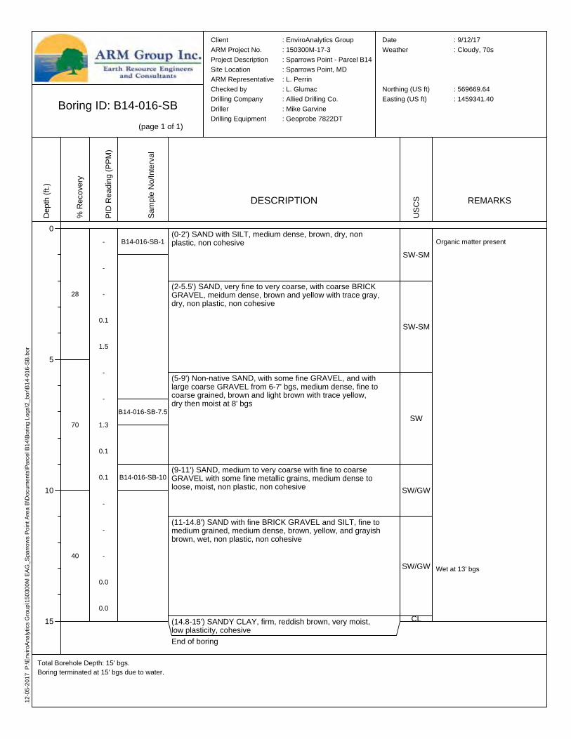
Boring ID: B14-016-SB(page 1 of 1)
Total Borehole Depth: 15' bgs.Boring terminated at 15' bgs due to water.
Client : EnviroAnalytics GroupARM Project No. : 150300M-17-3Project Description : Sparrows Point - Parcel B14Site Location : Sparrows Point, MDARM Representative : L. PerrinChecked by : L. GlumacDrilling Company : Allied Drilling Co.Driller : Mike GarvineDrilling Equipment : Geoprobe 7822DT
Date : 9/12/17Weather : Cloudy, 70s
Northing (US ft) : 569669.64Easting (US ft) : 1459341.40
Depth
(ft.)
0
5
10
15
% Re
cove
ry
28
70
40
PID R
eadin
g (PP
M)
-
-
-
0.1
1.5
-
-
1.3
0.1
0.1
-
-
-
0.0
0.0
Samp
le No
/Inter
val
B14-016-SB-1
B14-016-SB-10
B14-016-SB-7.5
DESCRIPTION
(0-2') SAND with SILT, medium dense, brown, dry, non plastic, non cohesive
(2-5.5') SAND, very fine to very coarse, with coarse BRICK GRAVEL, meidum dense, brown and yellow with trace gray, dry, non plastic, non cohesive
(5-9') Non-native SAND, with some fine GRAVEL, and with large coarse GRAVEL from 6-7' bgs, medium dense, fine to coarse grained, brown and light brown with trace yellow, dry then moist at 8' bgs
(9-11') SAND, medium to very coarse with fine to coarse GRAVEL with some fine metallic grains, medium dense to loose, moist, non plastic, non cohesive
(11-14.8') SAND with fine BRICK GRAVEL and SILT, fine to medium grained, medium dense, brown, yellow, and grayish brown, wet, non plastic, non cohesive
(14.8-15') SANDY CLAY, firm, reddish brown, very moist, low plasticity, cohesiveEnd of boring
USCS
SW-SM
SW-SM
SW
SW/GW
SW/GW
CL
REMARKS
Organic matter present
Wet at 13' bgs

12-05
-2017
P:\E
nviro
Analy
tics G
roup\1
5030
0M EA
G_Sp
arrow
s Poin
t Area
B\Do
cume
nts\Pa
rcel B
14\Bo
ring L
ogs\2
_bor\
B14-0
17-S
B.bor
Boring ID: B14-017-SB(page 1 of 1)
Total Borehole Depth: 20' bgs.Boring terminated at 20' bgs due to water and piezometer installation.
Client : EnviroAnalytics GroupARM Project No. : 150300M-17-3Project Description : Sparrows Point - Parcel B14Site Location : Sparrows Point, MDARM Representative : L. PerrinChecked by : L. GlumacDrilling Company : Allied Drilling Co.Driller : Mike GarvineDrilling Equipment : Geoprobe 7822DT
Date : 9/13/17Weather : Cloudy, 70s
Northing (US ft) : 569668.86Easting (US ft) : 1459715.98
Depth
(ft.)
0
5
10
15
20
% Re
cove
ry
74
72
40
30
PID R
eadin
g (PP
M)
-
0.3
0.9
13.9
1.6
-
7.2
7.5
0.7
1.3
-
-
-
-
-
-
-
-
-
-
Samp
le No
/Inter
val
B14-017-SB-1
B14-017-SB-4
B14-017-SB-10
DESCRIPTION
(0-1') SILTY SAND with some SLAG GRAVEL, loose, brown with gray, dry, non plastic, non cohesive(1-14.5') SLAG GRAVEL, fine to coarse, with SAND, medium dense to dense, gray and reddish brown, dry then moist from 4-9.5' bgs, moist at 9.5' bgs, wet at 14' bgs
(14.5-19.5') SLAG GRAVEL, fine, with SILT, loose, black and gray, wet, non plastic, non cohesive
(19.5-20') CLAY, soft, brownish gray and black, very moist, low plasticity, cohesiveEnd of boring
USCS
SM
GW
GP
CL
REMARKS
Wet at 14' bgs
Very small trace sheen, no odor from 14.5-15' bgs, light sheen 18-19.5' bgs
12-05
-2017
P:\E
nviro
Analy
tics G
roup\1
5030
0M EA
G_Sp
arrow
s Poin
t Area
B\Do
cume
nts\Pa
rcel B
14\Bo
ring L
ogs\2
_bor\
B14-0
18-S
B.bor
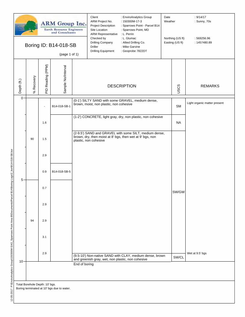
Boring ID: B14-018-SB(page 1 of 1)
Total Borehole Depth: 10' bgs.Boring terminated at 10' bgs due to water.
Client : EnviroAnalytics GroupARM Project No. : 150300M-17-3Project Description : Sparrows Point - Parcel B14Site Location : Sparrows Point, MDARM Representative : L. PerrinChecked by : L. GlumacDrilling Company : Allied Drilling Co.Driller : Mike GarvineDrilling Equipment : Geoprobe 7822DT
Date : 9/14/17Weather : Sunny, 70s
Northing (US ft) : 569256.96Easting (US ft) : 1457480.89
Depth
(ft.)
0
5
10
% Re
cove
ry
90
94
PID R
eadin
g (PP
M)
-
1.6
1.5
2.9
0.9
0.7
2.9
2.9
3.1
2.9
Samp
le No
/Inter
val
B14-018-SB-1
B14-018-SB-5
DESCRIPTION
(0-1') SILTY SAND with some GRAVEL, medium dense, brown, moist, non plastic, non cohesive
(1-2') CONCRETE, light gray, dry, non plastic, non cohesive
(2-9.5') SAND and GRAVEL with some SILT, medium dense, brown, dry, then moist at 8' bgs, then wet at 9' bgs, non plastic, non cohesive
(9.5-10') Non-native SAND with CLAY, medium dense, brown and greenish gray, wet, non plastic, non cohesiveEnd of boring
USCS
SM
NA
SW/GW
SW/CL
REMARKS
Wet at 9.5' bgs
Light organic matter present

12-05
-2017
P:\E
nviro
Analy
tics G
roup\1
5030
0M EA
G_Sp
arrow
s Poin
t Area
B\Do
cume
nts\Pa
rcel B
14\Bo
ring L
ogs\2
_bor\
B14-0
19-S
B.bor
Boring ID: B14-019-SB(page 1 of 1)
Total Borehole Depth: 8' bgs.Boring terminated at 8' bgs due to refusal.
Client : EnviroAnalytics GroupARM Project No. : 150300M-17-3Project Description : Sparrows Point - Parcel B14Site Location : Sparrows Point, MDARM Representative : L. PerrinChecked by : L. GlumacDrilling Company : Allied Drilling Co.Driller : Mike GarvineDrilling Equipment : Geoprobe 7822DT
Date : 9/6/17Weather : Cloudy, 70s
Northing (US ft) : 569299.17Easting (US ft) : 1457895.77
Depth
(ft.)
0
5
10
% Re
cove
ry
78
58
PID R
eadin
g (PP
M)
-
1.3
63.7
69.6
2.1
37.0
7.9
6.8
Samp
le No
/Inter
val
B14-019-SB-1
B14-019-SB-4
DESCRIPTION
(0-1') SILTY SAND with SLAG GRAVEL, loose to medium dense, reddish brown, moist, non plastic, non cohesive
(1-8') SLAG SAND and GRAVEL with trace SILT, medium dense, light brown, gray, and dark gray, dry to moist, non plastic, non cohesive
End of boring
USCS
SM
SW/GW
REMARKS
No water encountered
12-20
-2017
P:\E
nviro
Analy
tics G
roup\1
5030
0M EA
G_Sp
arrow
s Poin
t Area
B\Do
cume
nts\Pa
rcel B
14\Bo
ring L
ogs\2
_bor\
B14-0
20-S
B.bor
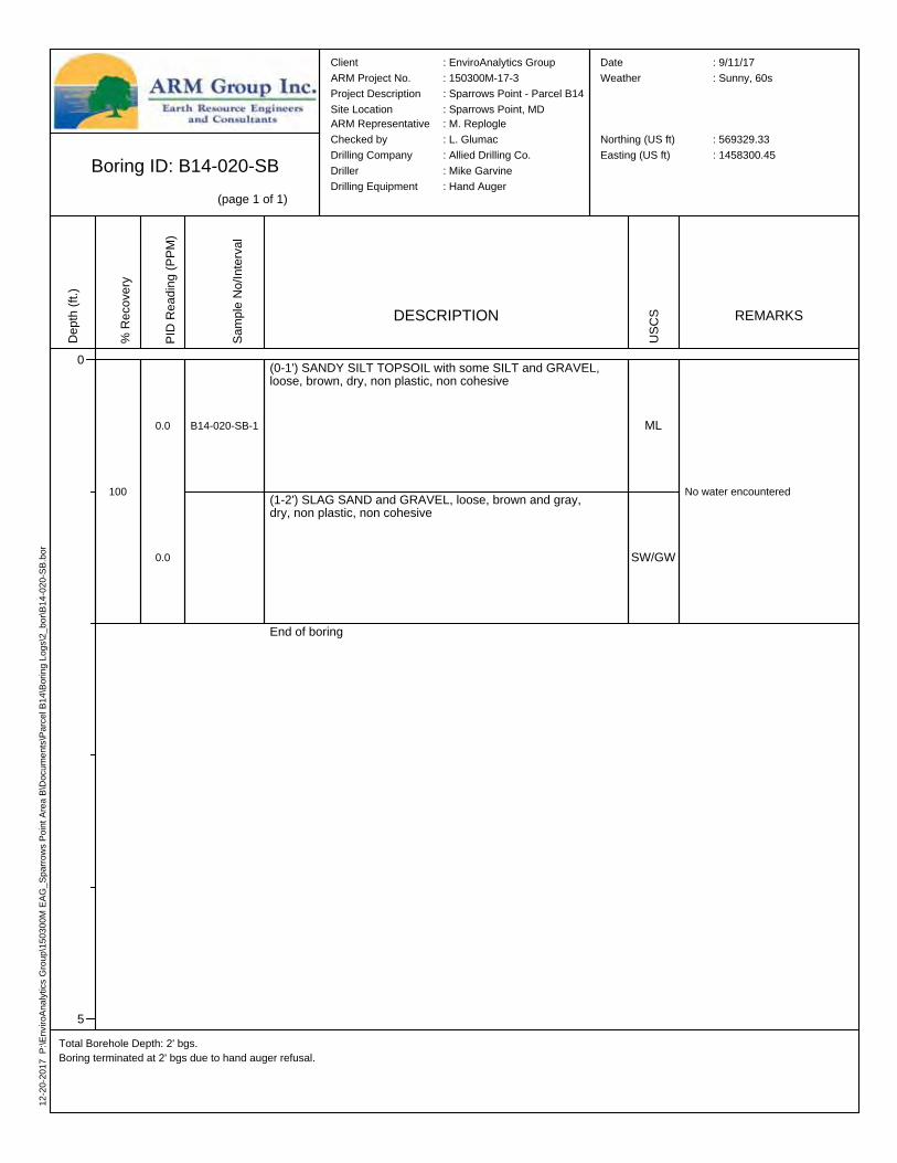
Boring ID: B14-020-SB(page 1 of 1)
Total Borehole Depth: 2' bgs.Boring terminated at 2' bgs due to hand auger refusal.
Depth
(ft.)
0
5
% Re
cove
ry
100
PID R
eadin
g (PP
M)
0.0
0.0
Samp
le No
/Inter
val
B14-020-SB-1
DESCRIPTION
USCS REMARKS
No water encountered
Client : EnviroAnalytics GroupARM Project No. : 150300M-17-3Project Description : Sparrows Point - Parcel B14Site Location : Sparrows Point, MDARM Representative : M. ReplogleChecked by : L. GlumacDrilling Company : Allied Drilling Co.Driller : Mike GarvineDrilling Equipment : Hand Auger
Date : 9/11/17Weather : Sunny, 60s
Northing (US ft) : 569329.33Easting (US ft) : 1458300.45
(0-1') SANDY SILT TOPSOIL with some SILT and GRAVEL, loose, brown, dry, non plastic, non cohesive
(1-2') SLAG SAND and GRAVEL, loose, brown and gray, dry, non plastic, non cohesive
End of boring
ML
SW/GW
12-05
-2017
P:\E
nviro
Analy
tics G
roup\1
5030
0M EA
G_Sp
arrow
s Poin
t Area
B\Do
cume
nts\Pa
rcel B
14\Bo
ring L
ogs\2
_bor\
B14-0
21-S
B.bor
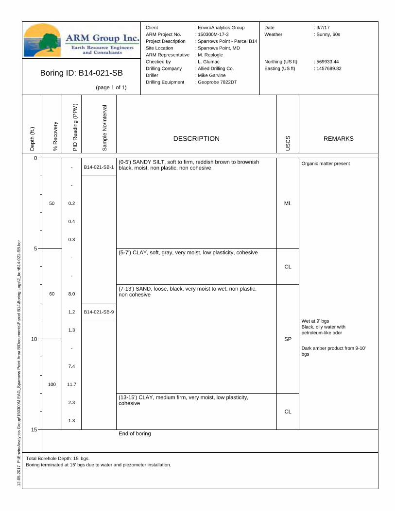
Boring ID: B14-021-SB(page 1 of 1)
Total Borehole Depth: 15' bgs.Boring terminated at 15' bgs due to water and piezometer installation.
Client : EnviroAnalytics GroupARM Project No. : 150300M-17-3Project Description : Sparrows Point - Parcel B14Site Location : Sparrows Point, MDARM Representative : M. ReplogleChecked by : L. GlumacDrilling Company : Allied Drilling Co.Driller : Mike GarvineDrilling Equipment : Geoprobe 7822DT
Date : 9/7/17Weather : Sunny, 60s
Northing (US ft) : 569933.44Easting (US ft) : 1457689.82
Depth
(ft.)
0
5
10
15
% Re
cove
ry
50
60
100
PID R
eadin
g (PP
M)
-
-
0.2
0.4
0.3
-
-
8.0
1.2
1.3
-
7.4
11.7
2.3
1.3
Samp
le No
/Inter
val
B14-021-SB-1
B14-021-SB-9
DESCRIPTION
(0-5') SANDY SILT, soft to firm, reddish brown to brownish black, moist, non plastic, non cohesive
(5-7') CLAY, soft, gray, very moist, low plasticity, cohesive
(7-13') SAND, loose, black, very moist to wet, non plastic, non cohesive
(13-15') CLAY, medium firm, very moist, low plasticity, cohesive
End of boring
USCS
ML
CL
SP
CL
REMARKS
Organic matter present
Wet at 9' bgsBlack, oily water with petroleum-like odor
Dark amber product from 9-10' bgs
12-05
-2017
P:\E
nviro
Analy
tics G
roup\1
5030
0M EA
G_Sp
arrow
s Poin
t Area
B\Do
cume
nts\Pa
rcel B
14\Bo
ring L
ogs\2
_bor\
B14-0
22-S
B.bor
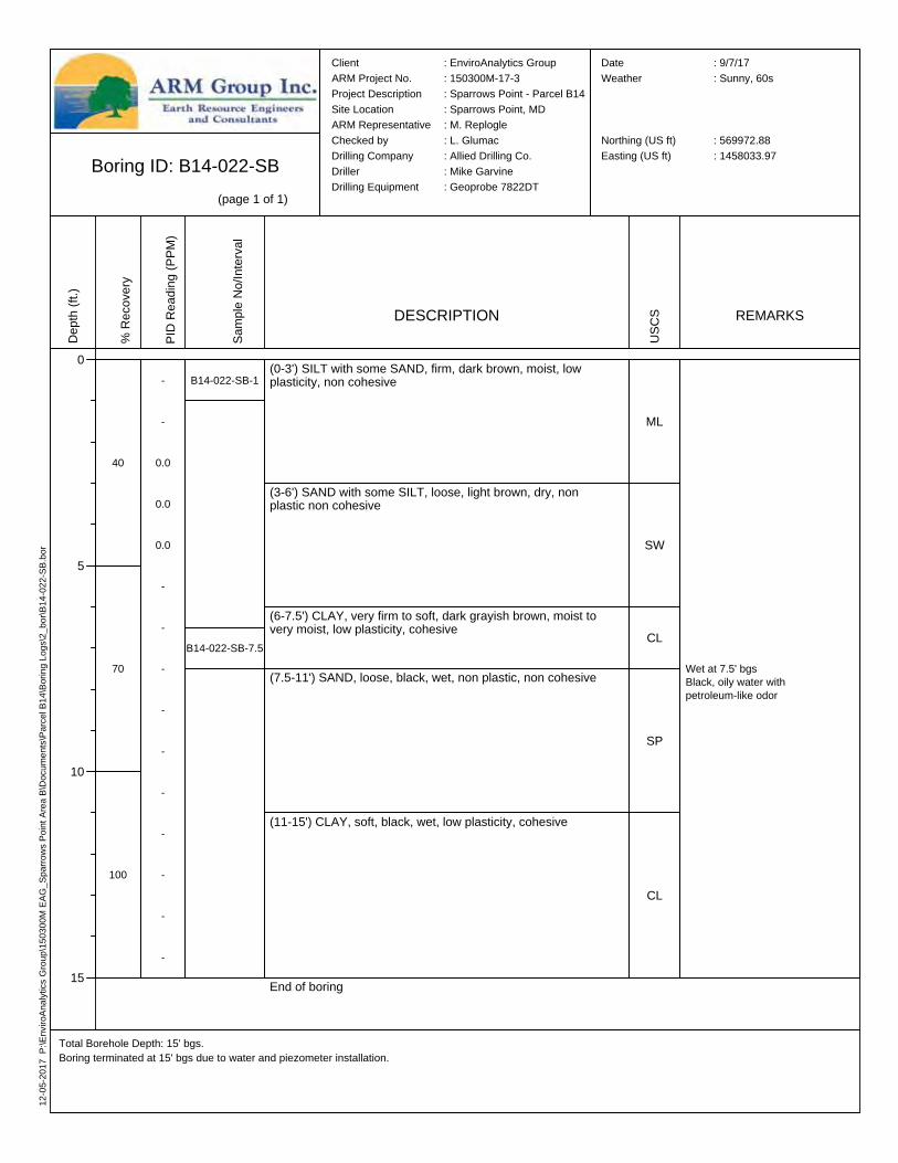
Boring ID: B14-022-SB(page 1 of 1)
Total Borehole Depth: 15' bgs.Boring terminated at 15' bgs due to water and piezometer installation.
Client : EnviroAnalytics GroupARM Project No. : 150300M-17-3Project Description : Sparrows Point - Parcel B14Site Location : Sparrows Point, MDARM Representative : M. ReplogleChecked by : L. GlumacDrilling Company : Allied Drilling Co.Driller : Mike GarvineDrilling Equipment : Geoprobe 7822DT
Date : 9/7/17Weather : Sunny, 60s
Northing (US ft) : 569972.88Easting (US ft) : 1458033.97
Depth
(ft.)
0
5
10
15
% Re
cove
ry
40
70
100
PID R
eadin
g (PP
M)
-
-
0.0
0.0
0.0
-
-
-
-
-
-
-
-
-
-
Samp
le No
/Inter
val
B14-022-SB-1
B14-022-SB-7.5
DESCRIPTION
(0-3') SILT with some SAND, firm, dark brown, moist, low plasticity, non cohesive
(3-6') SAND with some SILT, loose, light brown, dry, non plastic non cohesive
(6-7.5') CLAY, very firm to soft, dark grayish brown, moist to very moist, low plasticity, cohesive
(7.5-11') SAND, loose, black, wet, non plastic, non cohesive
(11-15') CLAY, soft, black, wet, low plasticity, cohesive
End of boring
USCS
ML
SW
CL
SP
CL
REMARKS
Wet at 7.5' bgsBlack, oily water with petroleum-like odor
12-05
-2017
P:\E
nviro
Analy
tics G
roup\1
5030
0M EA
G_Sp
arrow
s Poin
t Area
B\Do
cume
nts\Pa
rcel B
14\Bo
ring L
ogs\2
_bor\
B14-0
23-S
B.bor
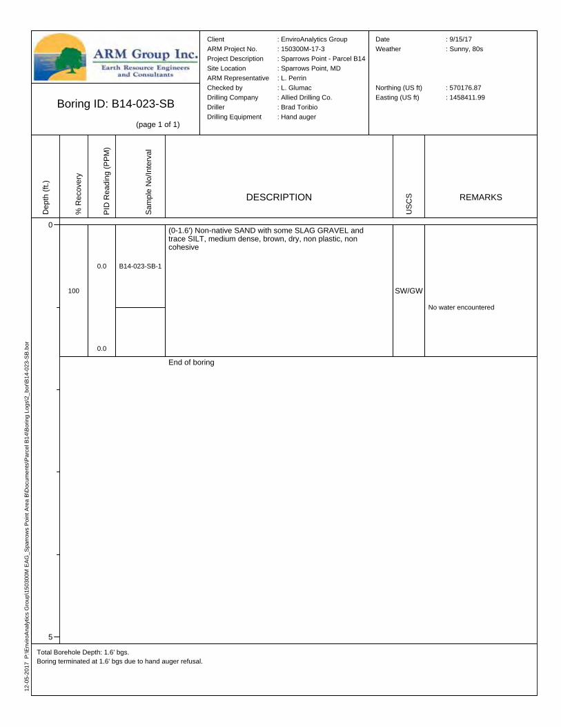
Boring ID: B14-023-SB(page 1 of 1)
Total Borehole Depth: 1.6' bgs.Boring terminated at 1.6' bgs due to hand auger refusal.
Client : EnviroAnalytics GroupARM Project No. : 150300M-17-3Project Description : Sparrows Point - Parcel B14Site Location : Sparrows Point, MDARM Representative : L. PerrinChecked by : L. GlumacDrilling Company : Allied Drilling Co.Driller : Brad ToribioDrilling Equipment : Hand auger
Date : 9/15/17Weather : Sunny, 80s
Northing (US ft) : 570176.87Easting (US ft) : 1458411.99
Depth
(ft.)
0
5
% Re
cove
ry
100
PID R
eadin
g (PP
M)
0.0
0.0
Samp
le No
/Inter
val
B14-023-SB-1
DESCRIPTION
(0-1.6') Non-native SAND with some SLAG GRAVEL and trace SILT, medium dense, brown, dry, non plastic, non cohesive
End of boring
USCS
SW/GW
REMARKS
No water encountered
12-05
-2017
P:\E
nviro
Analy
tics G
roup\1
5030
0M EA
G_Sp
arrow
s Poin
t Area
B\Do
cume
nts\Pa
rcel B
14\Bo
ring L
ogs\2
_bor\
B14-0
24-S
B.bor
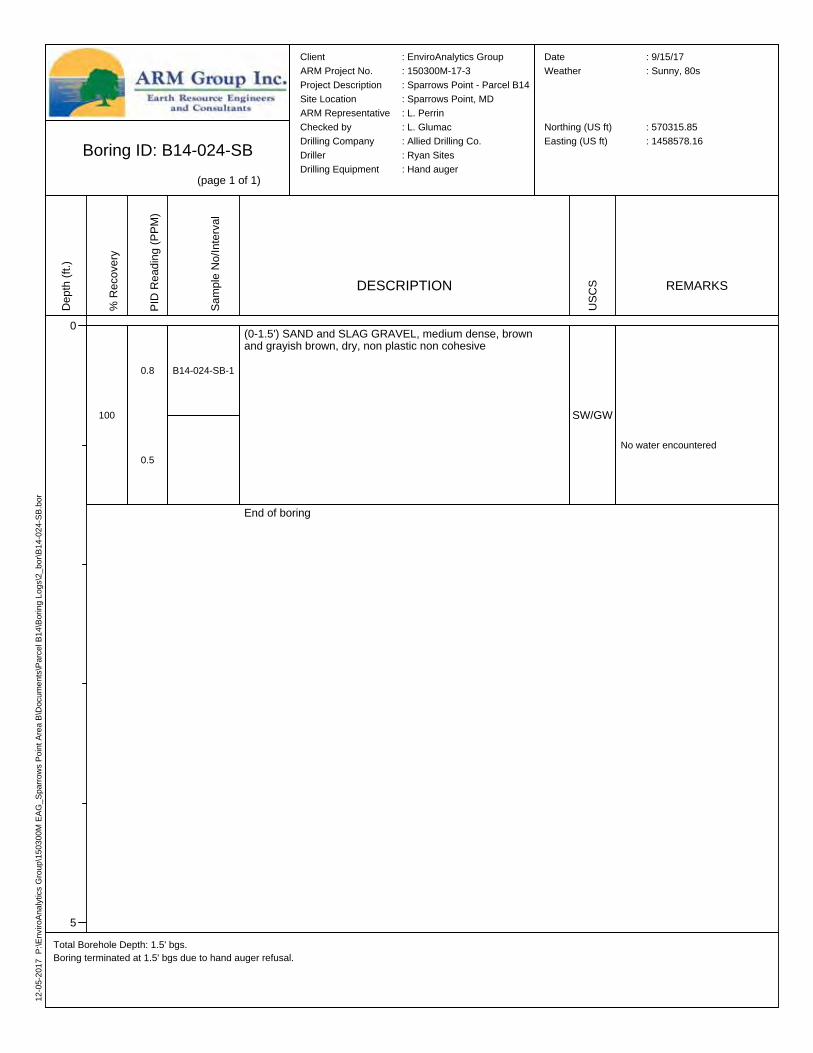
Boring ID: B14-024-SB(page 1 of 1)
Total Borehole Depth: 1.5' bgs.Boring terminated at 1.5' bgs due to hand auger refusal.
Client : EnviroAnalytics GroupARM Project No. : 150300M-17-3Project Description : Sparrows Point - Parcel B14Site Location : Sparrows Point, MDARM Representative : L. PerrinChecked by : L. GlumacDrilling Company : Allied Drilling Co.Driller : Ryan SitesDrilling Equipment : Hand auger
Date : 9/15/17Weather : Sunny, 80s
Northing (US ft) : 570315.85Easting (US ft) : 1458578.16
Depth
(ft.)
0
5
% Re
cove
ry
100
PID R
eadin
g (PP
M)
0.8
0.5
Samp
le No
/Inter
val
B14-024-SB-1
DESCRIPTION
(0-1.5') SAND and SLAG GRAVEL, medium dense, brown and grayish brown, dry, non plastic non cohesive
End of boring
USCS
SW/GW
REMARKS
No water encountered
12-05
-2017
P:\E
nviro
Analy
tics G
roup\1
5030
0M EA
G_Sp
arrow
s Poin
t Area
B\Do
cume
nts\Pa
rcel B
14\Bo
ring L
ogs\2
_bor\
B14-0
25-S
B.bor
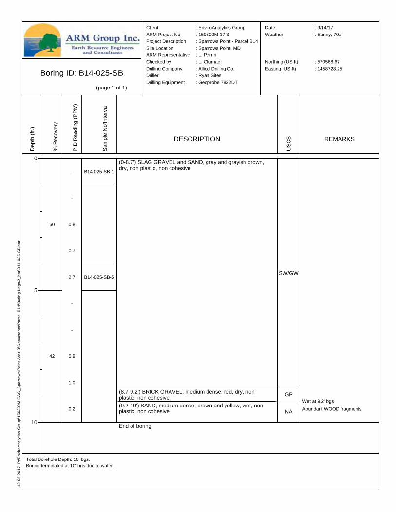
Boring ID: B14-025-SB(page 1 of 1)
Total Borehole Depth: 10' bgs.Boring terminated at 10' bgs due to water.
Client : EnviroAnalytics GroupARM Project No. : 150300M-17-3Project Description : Sparrows Point - Parcel B14Site Location : Sparrows Point, MDARM Representative : L. PerrinChecked by : L. GlumacDrilling Company : Allied Drilling Co.Driller : Ryan SitesDrilling Equipment : Geoprobe 7822DT
Date : 9/14/17Weather : Sunny, 70s
Northing (US ft) : 570568.67Easting (US ft) : 1458728.25
Depth
(ft.)
0
5
10
% Re
cove
ry
60
42
PID R
eadin
g (PP
M)
-
-
0.8
0.7
2.7
-
-
0.9
1.0
0.2
Samp
le No
/Inter
val
B14-025-SB-1
B14-025-SB-5
DESCRIPTION
(0-8.7') SLAG GRAVEL and SAND, gray and grayish brown, dry, non plastic, non cohesive
(8.7-9.2') BRICK GRAVEL, medium dense, red, dry, non plastic, non cohesive(9.2-10') SAND, medium dense, brown and yellow, wet, non plastic, non cohesive
End of boring
USCS
SW/GW
GP
NA
REMARKS
Wet at 9.2' bgsAbundant WOOD fragments

12-05
-2017
P:\E
nviro
Analy
tics G
roup\1
5030
0M EA
G_Sp
arrow
s Poin
t Area
B\Do
cume
nts\Pa
rcel B
14\Bo
ring L
ogs\2
_bor\
B14-0
26-S
B.bor
Boring ID: B14-026-SB(page 1 of 1)
Total Borehole Depth: 10' bgs.Boring terminated at 10' bgs due to water.
Client : EnviroAnalytics GroupARM Project No. : 150300M-17-3Project Description : Sparrows Point - Parcel B14Site Location : Sparrows Point, MDARM Representative : L. PerrinChecked by : L. GlumacDrilling Company : Allied Drilling Co.Driller : Ryan SitesDrilling Equipment : Geoprobe 7822DT
Date : 9/14/17Weather : Sunny, 70s
Northing (US ft) : 570658.38Easting (US ft) : 1458807.40
Depth
(ft.)
0
5
10
% Re
cove
ry
92
60
PID R
eadin
g (PP
M)
0.2
2.0
0.2
0.2
0.1
-
-
2.6
3.9
3.6
Samp
le No
/Inter
val
B14-026-SB-1
B14-026-SB-8.5
DESCRIPTION
(0-0.6') ORGANIC SILT, soft, dry, brown, non plastic, non cohesive(0.6-3.5') SAND with SILT, fine to medium, medium dense to dense, light brown and brown, dry, non plastic, non cohesive
(3.5-4') CLAY, hard, reddish yellow and light brownish gray, dry, low plasticity, cohesive(4-8.5') SANDY SILT with trace BRICK GRAVEL from 4-5' bgs, very firm, black with trace red, moist, non plastic, non cohesive
(8.5-9.8') CLAYEY SAND, dark brownish red, wet, non plastic, non cohesive
(9.8-10') CONCRETE GRAVEL, medium dense, very pale brown and brown, wet, non plastic, non cohesiveEnd of boring
USCS
OL
SW-SM
CL
ML
SC
NA
REMARKS
WOOD fragments with creosote-like odor present from 7-9.8' bgs
Wet at 8.5' bgs

12-05
-2017
P:\E
nviro
Analy
tics G
roup\1
5030
0M EA
G_Sp
arrow
s Poin
t Area
B\Do
cume
nts\Pa
rcel B
14\Bo
ring L
ogs\2
_bor\
B14-0
27-S
B.bor
Boring ID: B14-027-SB(page 1 of 1)
Total Borehole Depth: 20' bgs.Boring terminated at 20' bgs due to maximum allowable depth.
Client : EnviroAnalytics GroupARM Project No. : 150300M-17-3Project Description : Sparrows Point - Parcel B14Site Location : Sparrows Point, MDARM Representative : L. PerrinChecked by : L. GlumacDrilling Company : Allied Drilling Co.Driller : Ryan SitesDrilling Equipment : Geoprobe 7822DT
Date : 9/14/17Weather : Sunny, 80s
Northing (US ft) : 570806.21Easting (US ft) : 1459120.62
Depth
(ft.)
0
5
10
15
20
% Re
cove
ry
80
18
0.4
50
PID R
eadin
g (PP
M)
-0.2
0.2
2.9
0.1
-
-
-
-
0.0
-
-
-
-
2.7
-
-
0.2
0.0
0.0
Samp
le No
/Inter
val
B14-027-SB-1
B14-027-SB-5
B14-027-SB-10
DESCRIPTION
(0-1') SAND, very fine to medium, with CLAY and fine GRAVEL, medium dense, reddish yellow and light brown, moist, non plastic, non cohesive,(1-2') SANDY CLAY with some GRAVEL, very firm to hard, dry to moist, light brown with trace gray and yellow, low plasticity, cohesive(2-2.8') SAND with some GRAVEL, fine to coarse, medium dense, brown with gray, moist, non plastic, non cohesive(2.8-3.7') CLAY, hard, very pale brown, moist, low plasticity, cohesive(3.7-4.5') SAND with CLAY and GRAVEL, dense, very pale brown, very moist, non plastic, non cohesive(4.5-7.5') CLAY, hard, very pale brown, moist, low plasticity, cohesive
(7.5-9') SAND and BRICK GRAVEL with CLAY, medium dense, brown with trace yellow and red, very moist, non plastic, non cohesive(9-14.3') SANDY CLAY with GRAVEL, firm, brown with trace red, very moist, low plasticity, cohesive
(14.3-17.7') SILTY CLAY, soft, black, very moist, low plasticity, cohesive
(17.7-20') CLAY with trace SAND from 19.8-20' bgs, hard, very pale brown, dry to moist, low plasticity, cohesive
End of boring
USCS
SW-SC
CLSW/GW
CLSW-SC
CL
SW-SC
CL
CL
CL
REMARKS
No water encountered
12-05
-2017
P:\E
nviro
Analy
tics G
roup\1
5030
0M EA
G_Sp
arrow
s Poin
t Area
B\Do
cume
nts\Pa
rcel B
14\Bo
ring L
ogs\2
_bor\
B14-0
28-S
B.bor
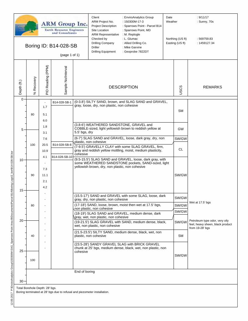
Boring ID: B14-028-SB(page 1 of 1)
Total Borehole Depth: 28' bgs.Boring terminated at 28' bgs due to refusal and piezometer installation.
Client : EnviroAnalytics GroupARM Project No. : 150300M-17-3Project Description : Sparrows Point - Parcel B14Site Location : Sparrows Point, MDARM Representative : M. ReplogleChecked by : L. GlumacDrilling Company : Allied Drilling Co.Driller : Mike GarvineDrilling Equipment : Geoprobe 7822DT
Date : 9/11/17Weather : Sunny, 70s
Northing (US ft) : 569759.83Easting (US ft) : 1459127.34
Depth
(ft.)
0
5
10
15
20
25
30
% Re
cove
ry
80
100
90
80
40
100
PID R
eadin
g (PP
M)
-1.7
5.16.01.83.17.6
20.510.94.1-
7.311.12.14.2----------
Samp
le No
/Inter
val
B14-028-SB-1
B14-028-SB-8
B14-028-SB-10
DESCRIPTION
(0-3.8') SILTY SAND, brown, and SLAG SAND and GRAVEL, gray, loose, dry, non plastic, non cohesive
(3.8-6') WEATHERED SANDSTONE, GRAVEL and COBBLE-sized, light yellowish brown to reddish yellow at 5.5' bgs, dry(6-7') SLAG SAND and GRAVEL, loose, dark gray, dry, non plastic, non cohesive(7-9.5') GRAVELLY CLAY with some SLAG GRAVEL, firm, gray and reddish yellow mottling, moist, medium plasticity, cohesive(9.5-15.5') SLAG SAND and GRAVEL, loose, dark gray, with some WEATHERED SANDSTONE pockets, SAND-sized, light yellowish brown, dry, non plastic, non cohesive
(15.5-17') SAND and GRAVEL with some SLAG, loose, dark gray, dry, non plastic, non cohesive(17-18') SAND, loose, brown, moist then wet at 17.5' bgs, non plastic, non cohesive(18-19') SLAG SAND and GRAVEL, medium dense, dark gray, wet, non plastic, non cohesive(19-21.5') SLAG GRAVEL with SAND, medium dense, black, wet, non plastic, non cohesive(21.5-23.5') SILTY SAND, medium dense, black, wet, non plastic, non cohesive
(23.5-28') SANDY GRAVEL SLAG with BRICK GRAVEL chunk at 25' bgs, medium dense, black, wet, non plastic, non cohesive
End of boring
USCS
SM
GW
SW/GW
CL
SW/GW
SW/GWSW/GWSW/GW
SW/GW
SM
SW/GW
REMARKS
Wet at 17.5' bgs
Petroleum type odor, very oily feel, heavy sheen, black product from 19-28' bgs

12-05
-2017
P:\E
nviro
Analy
tics G
roup\1
5030
0M EA
G_Sp
arrow
s Poin
t Area
B\Do
cume
nts\Pa
rcel B
14\Bo
ring L
ogs\2
_bor\
B14-0
29-S
B.bor
Boring ID: B14-029-SB(page 1 of 1)
Total Borehole Depth: 15' bgs.Boring terminated at 15' bgs due to water.
Client : EnviroAnalytics GroupARM Project No. : 150300M-17-3Project Description : Sparrows Point - Parcel B14Site Location : Sparrows Point, MDARM Representative : M. ReplogleChecked by : L. GlumacDrilling Company : Allied Drilling Co.Driller : Mike GarvineDrilling Equipment : Geoprobe 7822DT
Date : 9/11/17Weather : Sunny, 70s
Northing (US ft) : 569543.96Easting (US ft) : 1459096.23
Depth
(ft.)
0
5
10
15
% Re
cove
ry
50
60
10
PID R
eadin
g (PP
M)
-
-
0.8
7.3
2.4
-
3.0
2.4
1.6
2.0
-
-
-
-
-
Samp
le No
/Inter
val
B14-029-SB-1
B14-029-SB-5
B14-029-SB-10
DESCRIPTION
(0-1.5') SILTY SAND, loose, brown, dry, non plastic, non cohesive
(1.5-12') GRAVELLY SAND with some shiny large GRAVEL, medium dense, alternating 1 to 3-inch layers of dark gray, yellowish brown, light gray, and brown, non plastic, non cohesive
(12-15') SAND, loose, dark grayish brown, wet, non plastic, non cohesive
End of boring
USCS
SM
SW/GW
SW
REMARKS
Wet at 14.5' bgs
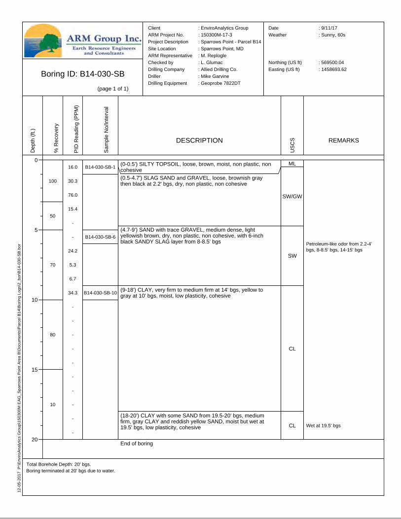
12-05
-2017
P:\E
nviro
Analy
tics G
roup\1
5030
0M EA
G_Sp
arrow
s Poin
t Area
B\Do
cume
nts\Pa
rcel B
14\Bo
ring L
ogs\2
_bor\
B14-0
30-S
B.bor
Boring ID: B14-030-SB(page 1 of 1)
Total Borehole Depth: 20' bgs.Boring terminated at 20' bgs due to water.
Client : EnviroAnalytics GroupARM Project No. : 150300M-17-3Project Description : Sparrows Point - Parcel B14Site Location : Sparrows Point, MDARM Representative : M. ReplogleChecked by : L. GlumacDrilling Company : Allied Drilling Co.Driller : Mike GarvineDrilling Equipment : Geoprobe 7822DT
Date : 9/11/17Weather : Sunny, 60s
Northing (US ft) : 569500.04Easting (US ft) : 1458693.62
Depth
(ft.)
0
5
10
15
20
% Re
cove
ry
100
50
70
80
10
PID R
eadin
g (PP
M)
16.0
30.3
76.0
15.4
-
-
24.2
5.3
6.7
34.3
-
-
-
-
-
-
-
-
-
-
Samp
le No
/Inter
val
B14-030-SB-1
B14-030-SB-6
B14-030-SB-10
DESCRIPTION
(0-0.5') SILTY TOPSOIL, loose, brown, moist, non plastic, non cohesive(0.5-4.7') SLAG SAND and GRAVEL, loose, brownish gray then black at 2.2' bgs, dry, non plastic, non cohesive
(4.7-9') SAND with trace GRAVEL, medium dense, light yellowish brown, dry, non plastic, non cohesive, with 6-inch black SANDY SLAG layer from 8-8.5' bgs
(9-18') CLAY, very firm to medium firm at 14' bgs, yellow to gray at 10' bgs, moist, low plasticity, cohesive
(18-20') CLAY with some SAND from 19.5-20' bgs, medium firm, gray CLAY and reddish yellow SAND, moist but wet at 19.5' bgs, low plasticity, cohesive
End of boring
USCS
ML
SW/GW
SW
CL
CL
REMARKS
Petroleum-like odor from 2.2-4' bgs, 8-8.5' bgs, 14-15' bgs
Wet at 19.5' bgs
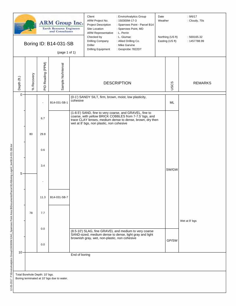
12-05
-2017
P:\E
nviro
Analy
tics G
roup\1
5030
0M EA
G_Sp
arrow
s Poin
t Area
B\Do
cume
nts\Pa
rcel B
14\Bo
ring L
ogs\2
_bor\
B14-0
31-S
B.bor
Boring ID: B14-031-SB(page 1 of 1)
Total Borehole Depth: 10' bgs.Boring terminated at 10' bgs due to water.
Client : EnviroAnalytics GroupARM Project No. : 150300M-17-3Project Description : Sparrows Point - Parcel B14Site Location : Sparrows Point, MDARM Representative : L. PerrinChecked by : L. GlumacDrilling Company : Allied Drilling Co.Driller : Mike GarvineDrilling Equipment : Geoprobe 7822DT
Date : 9/6/17Weather : Cloudy, 70s
Northing (US ft) : 569165.32Easting (US ft) : 1457788.99
Depth
(ft.)
0
5
10
% Re
cove
ry
80
78
PID R
eadin
g (PP
M)
-
6.7
29.8
0.6
3.4
-
11.3
7.7
0.0
0.0
Samp
le No
/Inter
val
B14-031-SB-1
B14-031-SB-7
DESCRIPTION
(0-1') SANDY SILT, firm, brown, moist, low plasticity, cohesive
(1-8.5') SAND, fine to very coarse, and GRAVEL, fine to coarse, with yellow BRICK COBBLES from 7-7.5' bgs, and trace CLAY lenses, medium dense to dense, brown, dry then wet at 8' bgs, non plastic, non cohesive
(8.5-10') SLAG, fine GRAVEL and medium to very coarse SAND-sized, medium dense to dense, light gray and light brownish gray, wet, non-plastic, non cohesive
End of boring
USCS
ML
SW/GW
GP/SW
REMARKS
Wet at 8' bgs
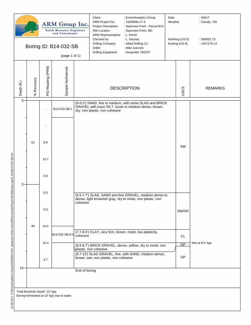
12-05
-2017
P:\E
nviro
Analy
tics G
roup\1
5030
0M EA
G_Sp
arrow
s Poin
t Area
B\Do
cume
nts\Pa
rcel B
14\Bo
ring L
ogs\2
_bor\
B14-0
32-S
B.bor
Boring ID: B14-032-SB(page 1 of 1)
Total Borehole Depth: 10' bgs.Boring terminated at 10' bgs due to water.
Client : EnviroAnalytics GroupARM Project No. : 150300M-17-3Project Description : Sparrows Point - Parcel B14Site Location : Sparrows Point, MDARM Representative : L. PerrinChecked by : L. GlumacDrilling Company : Allied Drilling Co.Driller : Mike GarvineDrilling Equipment : Geoprobe 7822DT
Date : 9/6/17Weather : Cloudy, 70s
Northing (US ft) : 569352.73Easting (US ft) : 1457276.14
Depth
(ft.)
0
5
10
% Re
cove
ry
62
90
PID R
eadin
g (PP
M)
-
-
8.9
10.7
0.9
0.0
0.0
10.5
15.4
3.7
Samp
le No
/Inter
val
B14-032-SB-1
B14-032-SB-8.5
DESCRIPTION
(0-5.5') SAND, fine to medium, with some SLAG and BRICK GRAVEL with trace SILT, loose to medium dense, brown, dry, non plastic, non cohesive
(5.5-7.7') SLAG, SAND and fine GRAVEL, medium dense to dense, light brownish gray, dry to moist, non plastic, non cohesive
(7.7-8.5') CLAY, very firm, brown, moist, low plasticity, cohesive
(8.5-8.7') BRICK GRAVEL, dense, yellow, dry to moist, non plastic, non cohesive(8.7-10') SLAG GRAVEL, fine, with SAND, medium dense, brown, wet, non plastic, non cohesive
End of boring
USCS
SW
SW/GP
CL
GP
GP
REMARKS
Wet at 8.5' bgs
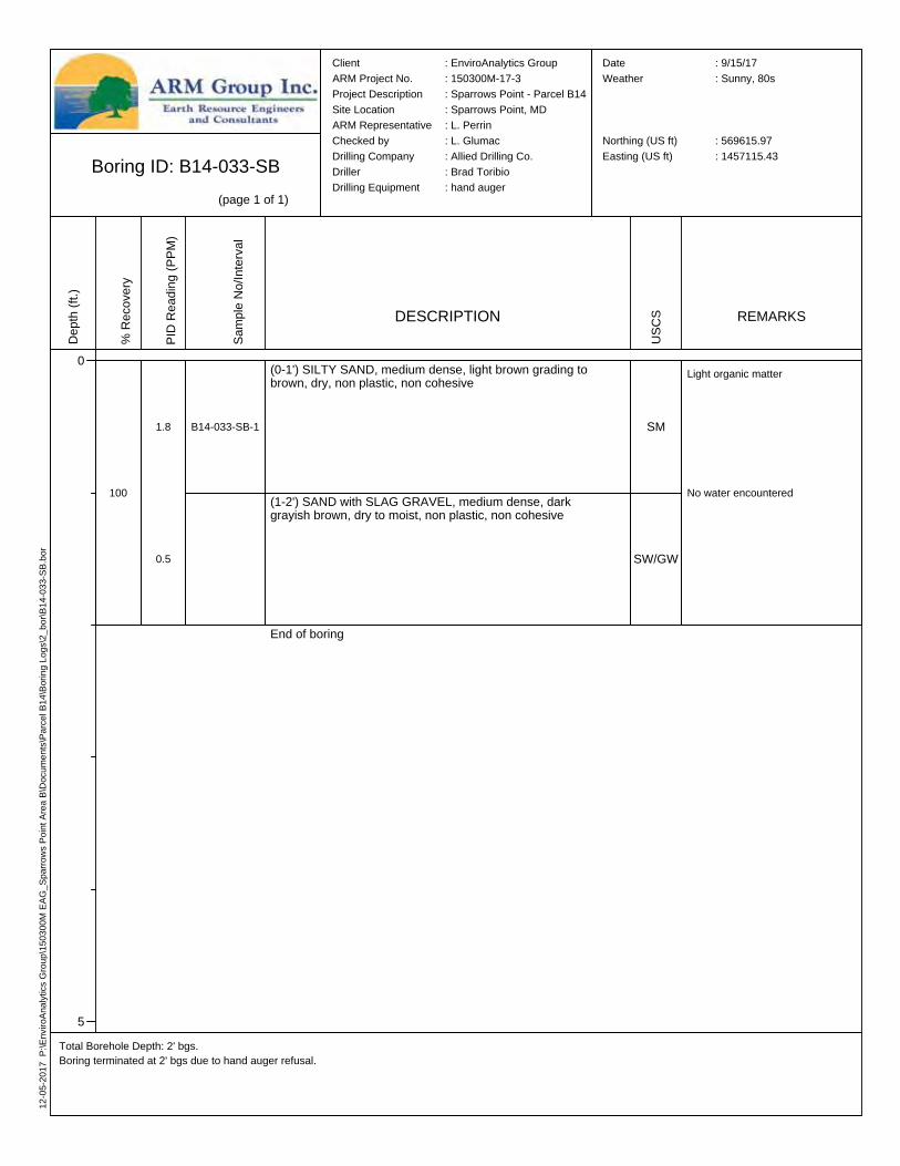
12-05
-2017
P:\E
nviro
Analy
tics G
roup\1
5030
0M EA
G_Sp
arrow
s Poin
t Area
B\Do
cume
nts\Pa
rcel B
14\Bo
ring L
ogs\2
_bor\
B14-0
33-S
B.bor
Boring ID: B14-033-SB(page 1 of 1)
Total Borehole Depth: 2' bgs.Boring terminated at 2' bgs due to hand auger refusal.
Client : EnviroAnalytics GroupARM Project No. : 150300M-17-3Project Description : Sparrows Point - Parcel B14Site Location : Sparrows Point, MDARM Representative : L. PerrinChecked by : L. GlumacDrilling Company : Allied Drilling Co.Driller : Brad ToribioDrilling Equipment : hand auger
Date : 9/15/17Weather : Sunny, 80s
Northing (US ft) : 569615.97Easting (US ft) : 1457115.43
Depth
(ft.)
0
5
% Re
cove
ry
100
PID R
eadin
g (PP
M)
1.8
0.5
Samp
le No
/Inter
val
B14-033-SB-1
DESCRIPTION
(0-1') SILTY SAND, medium dense, light brown grading to brown, dry, non plastic, non cohesive
(1-2') SAND with SLAG GRAVEL, medium dense, dark grayish brown, dry to moist, non plastic, non cohesive
End of boringUS
CS
SM
SW/GW
REMARKS
Light organic matter
No water encountered
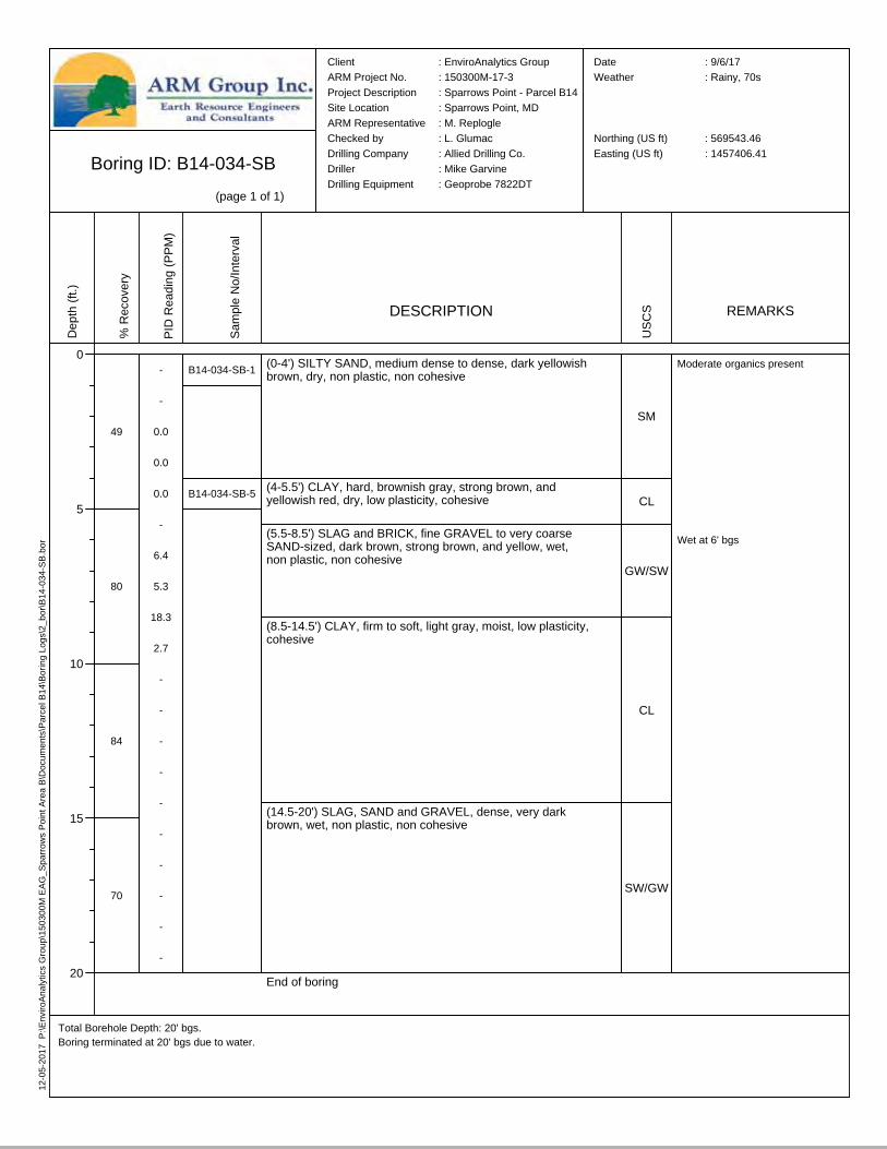
12-05
-2017
P:\E
nviro
Analy
tics G
roup\1
5030
0M EA
G_Sp
arrow
s Poin
t Area
B\Do
cume
nts\Pa
rcel B
14\Bo
ring L
ogs\2
_bor\
B14-0
34-S
B.bor
Boring ID: B14-034-SB(page 1 of 1)
Total Borehole Depth: 20' bgs.Boring terminated at 20' bgs due to water.
Client : EnviroAnalytics GroupARM Project No. : 150300M-17-3Project Description : Sparrows Point - Parcel B14Site Location : Sparrows Point, MDARM Representative : M. ReplogleChecked by : L. GlumacDrilling Company : Allied Drilling Co.Driller : Mike GarvineDrilling Equipment : Geoprobe 7822DT
Date : 9/6/17Weather : Rainy, 70s
Northing (US ft) : 569543.46Easting (US ft) : 1457406.41
Depth
(ft.)
0
5
10
15
20
% Re
cove
ry
49
80
84
70
PID R
eadin
g (PP
M)
-
-
0.0
0.0
0.0
-
6.4
5.3
18.3
2.7
-
-
-
-
-
-
-
-
-
-
Samp
le No
/Inter
val
B14-034-SB-1
B14-034-SB-5
DESCRIPTION
(0-4') SILTY SAND, medium dense to dense, dark yellowish brown, dry, non plastic, non cohesive
(4-5.5') CLAY, hard, brownish gray, strong brown, and yellowish red, dry, low plasticity, cohesive
(5.5-8.5') SLAG and BRICK, fine GRAVEL to very coarse SAND-sized, dark brown, strong brown, and yellow, wet, non plastic, non cohesive
(8.5-14.5') CLAY, firm to soft, light gray, moist, low plasticity, cohesive
(14.5-20') SLAG, SAND and GRAVEL, dense, very dark brown, wet, non plastic, non cohesive
End of boring
USCS
SM
CL
GW/SW
CL
SW/GW
REMARKS
Moderate organics present
Wet at 6' bgs
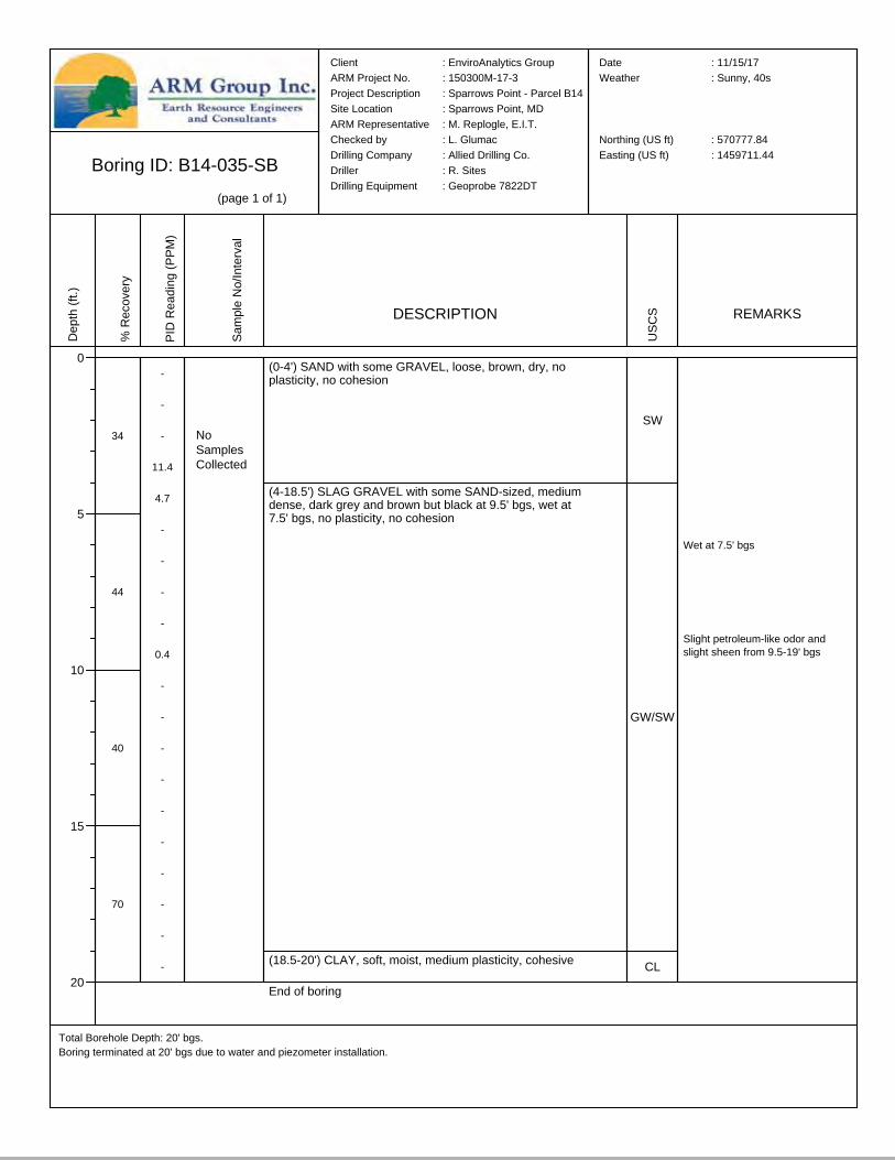
Boring ID: B14-035-SB(page 1 of 1)
Total Borehole Depth: 20' bgs.Boring terminated at 20' bgs due to water and piezometer installation.
Client : EnviroAnalytics GroupARM Project No. : 150300M-17-3Project Description : Sparrows Point - Parcel B14Site Location : Sparrows Point, MDARM Representative : M. Replogle, E.I.T.Checked by : L. GlumacDrilling Company : Allied Drilling Co.Driller : R. SitesDrilling Equipment : Geoprobe 7822DT
Date : 11/15/17Weather : Sunny, 40s
Northing (US ft) : 570777.84Easting (US ft) : 1459711.44
Depth
(ft.)
0
5
10
15
20
% Re
cove
ry
34
44
40
70
PID R
eadin
g (PP
M)
-
-
-
11.4
4.7
-
-
-
-
0.4
-
-
-
-
-
-
-
-
-
-
Samp
le No
/Inter
val
DESCRIPTION
(0-4') SAND with some GRAVEL, loose, brown, dry, no plasticity, no cohesion
(4-18.5') SLAG GRAVEL with some SAND-sized, medium dense, dark grey and brown but black at 9.5' bgs, wet at 7.5' bgs, no plasticity, no cohesion
(18.5-20') CLAY, soft, moist, medium plasticity, cohesive
End of boring
USCS
SW
GW/SW
CL
REMARKS
Slight petroleum-like odor and slight sheen from 9.5-19' bgs
Wet at 7.5' bgs
NoSamplesCollected

Boring ID: B14-036-SB(page 1 of 1)
Total Borehole Depth: 20' bgs.Boring terminated at 20' bgs due to piezometer installation.
Client : EnviroAnalytics GroupARM Project No. : 150300M-17-3Project Description : Sparrows Point - Parcel B14Site Location : Sparrows Point, MDARM Representative : L. PerrinChecked by : L. GlumacDrilling Company : Allied Drilling Co.Driller : R. SitesDrilling Equipment : Geoprobe 7822DT
Date : 11/22/17Weather : Cloudy, 40s
Northing (US ft) : 569767.58Easting (US ft) : 1457678.02
Depth
(ft.)
0
5
10
15
20
% Re
cove
ry
20
20
40
60
PID R
eadin
g (PP
M)
-
-
-
-
0.0
-
-
-
-
0.0
-
-
-
0.0
0.0
-
-
0.0
0.0
0.0
Samp
le No
/Inter
val
DESCRIPTION
(0-1') SILTY SAND, medium dense, reddish brown, moist, no plasticity, no cohesion(1-15') CLAY, soft, greenish gray, moist to very moist, low plasticity, cohesive
(15-20') Soils not logged
End of boring
USCS
SM
CL
CL
REMARKS
No water encountered
NoSamplesCollected

Boring ID: B14-037-SB(page 1 of 1)
Total Borehole Depth: 20' bgs.Boring terminated at 20' bgs due to piezometer installation.
Client : EnviroAnalytics GroupARM Project No. : 150300M-17-3Project Description : Sparrows Point - Parcel B14Site Location : Sparrows Point, MDARM Representative : L. PerrinChecked by : L. GlumacDrilling Company : Allied Drilling Co.Driller : R. SitesDrilling Equipment : Geoprobe 7822DT
Date : 11/14/17Weather : Cloudy, 40s
Northing (US ft) : 569480.98Easting (US ft) : 1457196.68
Depth
(ft.)
0
5
10
15
20
% Re
cove
ry
50
22
44
100
PID R
eadin
g (PP
M)
-
-
-
14.0
1.2
-
-
-
0.5
3.3
-
-
0.0
4.3
0.0
-
-
-
5.6
1.2
Samp
le No
/Inter
val
DESCRIPTION
(0-4.5') Non-native SAND with fine GRAVEL and SILT, medium dense, brown with trace yellow, dry, no plasticity, no cohesion
(4.5-15') BRICK and SLAG GRAVEL with SILT, medium dense to dense at 9.8' bgs, red to dark reddish brown at 9.8' bgs, dry but wet at 9.8' bgs, no plasticity, no cohesion
(15-19') CLAYEY SILT, soft, black, wet, low plasticity, cohesive
(19-19.5') SILTY CLAY, firm to soft, greenish gray and black mottling, very moist to moist, low plasticity, cohesive(19.5-20') SAND, fine to medium, with CLAY, medium dense, brownish gray with some black mottling, wet, no plasticity, no cohesionEnd of boring
USCS
SW/GP
GW-GM
ML
CLSW-SC
REMARKS
Wet at 9.5' bgsTrace sheen from 9.8-15' bgs
Strong petroleum-like odor with light sheen from 15-19' bgs, no visible product
NoSamplesCollected

Boring ID: B14-038-SB(page 1 of 1)
Total Borehole Depth: 20' bgs.Boring terminated at 20' bgs due to water and piezometer installation.
Client : EnviroAnalytics GroupARM Project No. : 150300M-17-3Project Description : Sparrows Point - Parcel B14Site Location : Sparrows Point, MDARM Representative : L. PerrinChecked by : L. GlumacDrilling Company : Allied Drilling Co.Driller : R. SitesDrilling Equipment : Geoprobe 7822DT
Date : 11/14/17Weather : Cloudy, 40s
Northing (US ft) : 569414.22Easting (US ft) : 1458151.98
Depth
(ft.)
0
5
10
15
20
% Re
cove
ry
20
24
50
52
PID R
eadin
g (PP
M)
-
-
-
-
0.6
-
-
-
-
0.2
-
-
-
24.7
4.1
-
-
0.0
0.6
1.2
Samp
le No
/Inter
val
DESCRIPTION
(0-13.5') SILTY CLAY with some SAND, firm to very firm, brownish red with trace black streaks from 12.5-13' bgs, moist, low plasticity, cohesive
(13.5-14.2') SAND, fine to medium, greenish gray and black, wet, no plasticity, no cohesion(14.2-17.5') SILTY CLAY, firm, black, very moist, low plasticity, cohesive
(17.5-20') CLAY, firm to very firm, greenish gray with some black streaks, moist, low plasticity, cohesive
End of boring
USCS
CL
SW
CL
CL
REMARKS
Moderate petroleum-like odor from 13.5-17.5' bgsTrace visible product at 14' bgs
Wet at 13.5' bgs
NoSamplesCollected
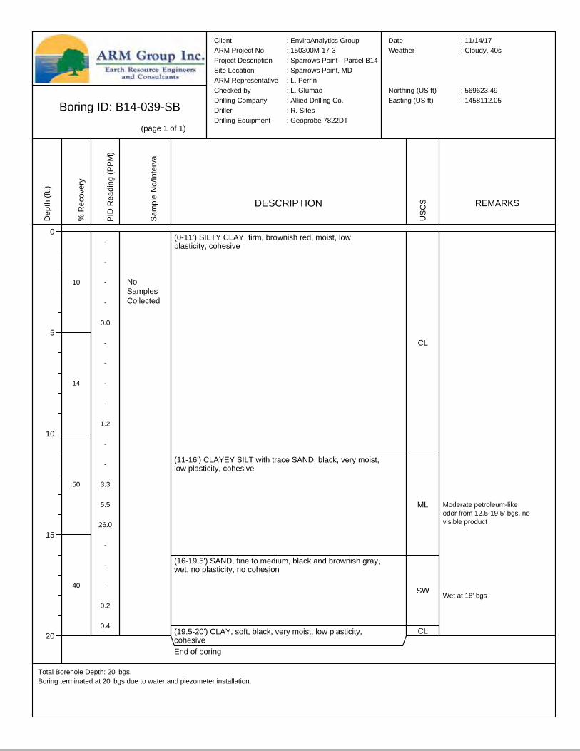
Boring ID: B14-039-SB(page 1 of 1)
Total Borehole Depth: 20' bgs.Boring terminated at 20' bgs due to water and piezometer installation.
Client : EnviroAnalytics GroupARM Project No. : 150300M-17-3Project Description : Sparrows Point - Parcel B14Site Location : Sparrows Point, MDARM Representative : L. PerrinChecked by : L. GlumacDrilling Company : Allied Drilling Co.Driller : R. SitesDrilling Equipment : Geoprobe 7822DT
Date : 11/14/17Weather : Cloudy, 40s
Northing (US ft) : 569623.49Easting (US ft) : 1458112.05
Depth
(ft.)
0
5
10
15
20
% Re
cove
ry
10
14
50
40
PID R
eadin
g (PP
M)
-
-
-
-
0.0
-
-
-
-
1.2
-
-
3.3
5.5
26.0
-
-
-
0.2
0.4
Samp
le No
/Inter
val
DESCRIPTION
(0-11') SILTY CLAY, firm, brownish red, moist, low plasticity, cohesive
(11-16') CLAYEY SILT with trace SAND, black, very moist, low plasticity, cohesive
(16-19.5') SAND, fine to medium, black and brownish gray, wet, no plasticity, no cohesion
(19.5-20') CLAY, soft, black, very moist, low plasticity, cohesiveEnd of boring
USCS
CL
ML
SW
CL
REMARKS
Moderate petroleum-like odor from 12.5-19.5' bgs, no visible product
Wet at 18' bgs
NoSamplesCollected
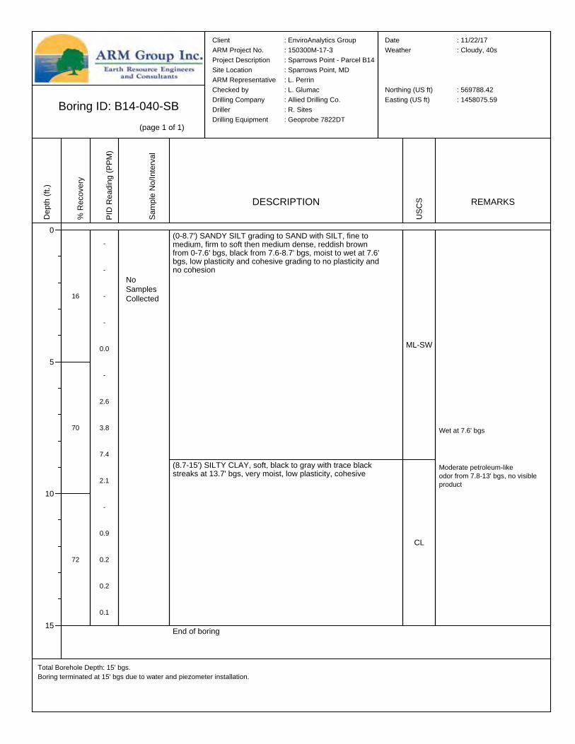
Boring ID: B14-040-SB(page 1 of 1)
Total Borehole Depth: 15' bgs.Boring terminated at 15' bgs due to water and piezometer installation.
Client : EnviroAnalytics GroupARM Project No. : 150300M-17-3Project Description : Sparrows Point - Parcel B14Site Location : Sparrows Point, MDARM Representative : L. PerrinChecked by : L. GlumacDrilling Company : Allied Drilling Co.Driller : R. SitesDrilling Equipment : Geoprobe 7822DT
Date : 11/22/17Weather : Cloudy, 40s
Northing (US ft) : 569788.42Easting (US ft) : 1458075.59
Depth
(ft.)
0
5
10
15
% Re
cove
ry
16
70
72
PID R
eadin
g (PP
M)
-
-
-
-
0.0
-
2.6
3.8
7.4
2.1
-
0.9
0.2
0.2
0.1
Samp
le No
/Inter
val
DESCRIPTION
(0-8.7') SANDY SILT grading to SAND with SILT, fine to medium, firm to soft then medium dense, reddish brown from 0-7.6' bgs, black from 7.6-8.7' bgs, moist to wet at 7.6' bgs, low plasticity and cohesive grading to no plasticity and no cohesion
(8.7-15') SILTY CLAY, soft, black to gray with trace black streaks at 13.7' bgs, very moist, low plasticity, cohesive
End of boring
USCS
ML-SW
CL
REMARKS
Moderate petroleum-like odor from 7.8-13' bgs, no visible product
Wet at 7.6' bgs
NoSamplesCollected
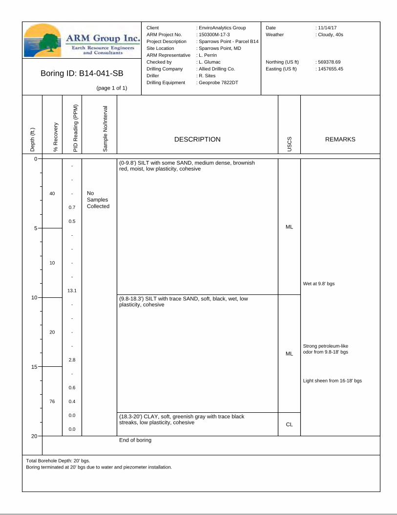
Boring ID: B14-041-SB(page 1 of 1)
Total Borehole Depth: 20' bgs.Boring terminated at 20' bgs due to water and piezometer installation.
Client : EnviroAnalytics GroupARM Project No. : 150300M-17-3Project Description : Sparrows Point - Parcel B14Site Location : Sparrows Point, MDARM Representative : L. PerrinChecked by : L. GlumacDrilling Company : Allied Drilling Co.Driller : R. SitesDrilling Equipment : Geoprobe 7822DT
Date : 11/14/17Weather : Cloudy, 40s
Northing (US ft) : 569378.69Easting (US ft) : 1457655.45
Depth
(ft.)
0
5
10
15
20
% Re
cove
ry
40
10
20
76
PID R
eadin
g (PP
M)
-
-
-
0.7
0.5
-
-
-
-
13.1
-
-
-
-
2.8
-
0.6
0.4
0.0
0.0
Samp
le No
/Inter
val
DESCRIPTION
(0-9.8') SILT with some SAND, medium dense, brownish red, moist, low plasticity, cohesive
(9.8-18.3') SILT with trace SAND, soft, black, wet, low plasticity, cohesive
(18.3-20') CLAY, soft, greenish gray with trace black streaks, low plasticity, cohesive
End of boring
USCS
ML
ML
CL
REMARKS
Strong petroleum-like odor from 9.8-18' bgs
Light sheen from 16-18' bgs
Wet at 9.8' bgs
NoSamplesCollected
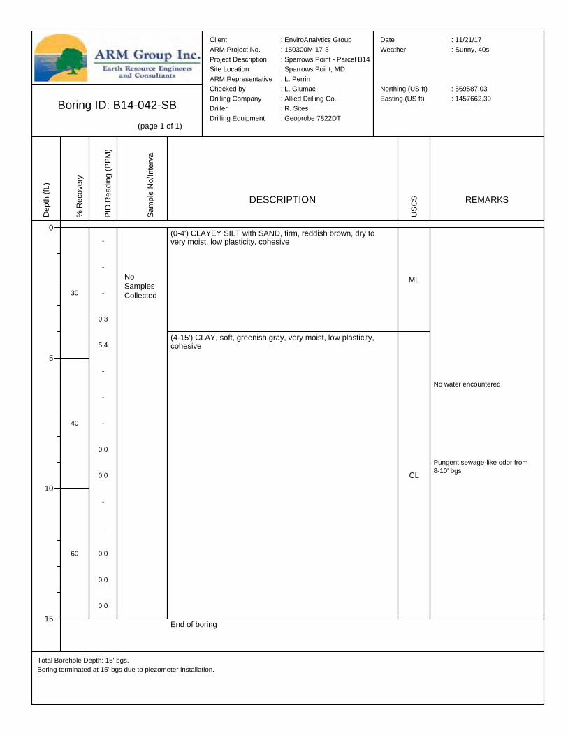
Boring ID: B14-042-SB(page 1 of 1)
Total Borehole Depth: 15' bgs.Boring terminated at 15' bgs due to piezometer installation.
Client : EnviroAnalytics GroupARM Project No. : 150300M-17-3Project Description : Sparrows Point - Parcel B14Site Location : Sparrows Point, MDARM Representative : L. PerrinChecked by : L. GlumacDrilling Company : Allied Drilling Co.Driller : R. SitesDrilling Equipment : Geoprobe 7822DT
Date : 11/21/17Weather : Sunny, 40s
Northing (US ft) : 569587.03Easting (US ft) : 1457662.39
Depth
(ft.)
0
5
10
15
% Re
cove
ry
30
40
60
PID R
eadin
g (PP
M)
-
-
-
0.3
5.4
-
-
-
0.0
0.0
-
-
0.0
0.0
0.0
Samp
le No
/Inter
val
DESCRIPTION
(0-4') CLAYEY SILT with SAND, firm, reddish brown, dry to very moist, low plasticity, cohesive
(4-15') CLAY, soft, greenish gray, very moist, low plasticity, cohesive
End of boring
USCS
ML
CL
REMARKS
Pungent sewage-like odor from 8-10' bgs
No water encountered
NoSamplesCollected
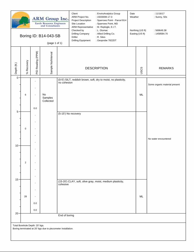
Boring ID: B14-043-SB(page 1 of 1)
Total Borehole Depth: 20' bgs.Boring terminated at 20' bgs due to piezometer installation.
Client : EnviroAnalytics GroupARM Project No. : 150300M-17-3Project Description : Sparrows Point - Parcel B14Site Location : Sparrows Point, MDARM Representative : M. Replogle, E.I.T.Checked by : L. GlumacDrilling Company : Allied Drilling Co.Driller : R. SitesDrilling Equipment : Geoprobe 7822DT
Date : 11/16/17Weather : Sunny, 50s
Northing (US ft) : 569649.38Easting (US ft) : 1458584.70
Depth
(ft.)
0
5
10
15
20
% Re
cove
ry
6
0
2
28
PID R
eadin
g (PP
M)
-
-
-
0.0
-
-
-
-
-
-
-
-
-
-
-
-
-
0.0
0.0
Samp
le No
/Inter
val
DESCRIPTION
(0-5') SILT, reddish brown, soft, dry to moist, no plasticity, no cohesion
(5-15') No recovery
(15-20') CLAY, soft, olive gray, moist, medium plasticity, cohesive
End of boring
USCS
ML
ML
REMARKS
Some organic material present
No water encountered
NoSamplesCollected
APPENDIX B
Piezometer Location Map and
Typical Construction Log
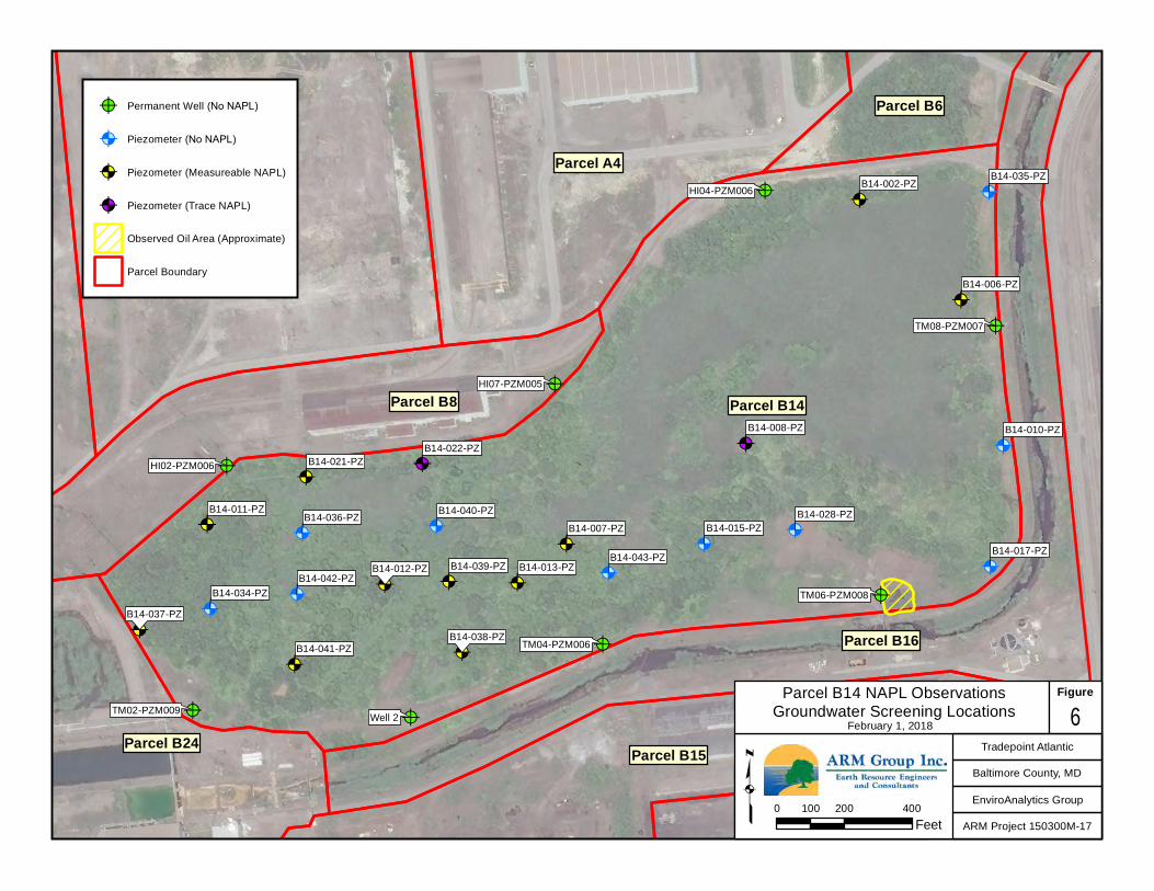
@?
@?
@?
@?
@?
@?
@?
@?
@A
@A @A
@A
@A
@A
@A
@A
@A
@A
@A
@A
@A
@A
@A
@A
@A
@A
@A
@A
@A
@A
@A
Parcel A1
Parcel A4
Parcel B23
Parcel B15Parcel B24
Parcel B8 Parcel B14
Parcel B16
Parcel B6
B14-011-PZ
B14-012-PZ B14-013-PZ
B14-015-PZ
B14-008-PZ
B14-017-PZ
B14-010-PZ
B14-002-PZ
B14-006-PZ
B14-021-PZ
B14-028-PZ
B14-022-PZ
B14-034-PZ
B14-036-PZ
B14-042-PZ
B14-041-PZ
B14-040-PZ
B14-039-PZ
B14-038-PZ
B14-035-PZ
B14-037-PZ
B14-043-PZ
B14-007-PZ
HI02-PZM006
HI04-PZM006
HI07-PZM005
TM02-PZM009
TM04-PZM006
TM06-PZM008
TM08-PZM007
Well 2
Tradepoint Atlantic
Baltimore County, MD
EnviroAnalytics Group
ARM Project 150300M-17
Parcel B14 NAPL ObservationsGroundwater Screening Locations 6
Figure
February 1, 2018
0 200 400100Feetq
@? Permanent Well (No NAPL)
@A Piezometer (No NAPL)
@A Piezometer (Measureable NAPL)
@A Piezometer (Trace NAPL)
Observed Oil Area (Approximate)
Parcel Boundary
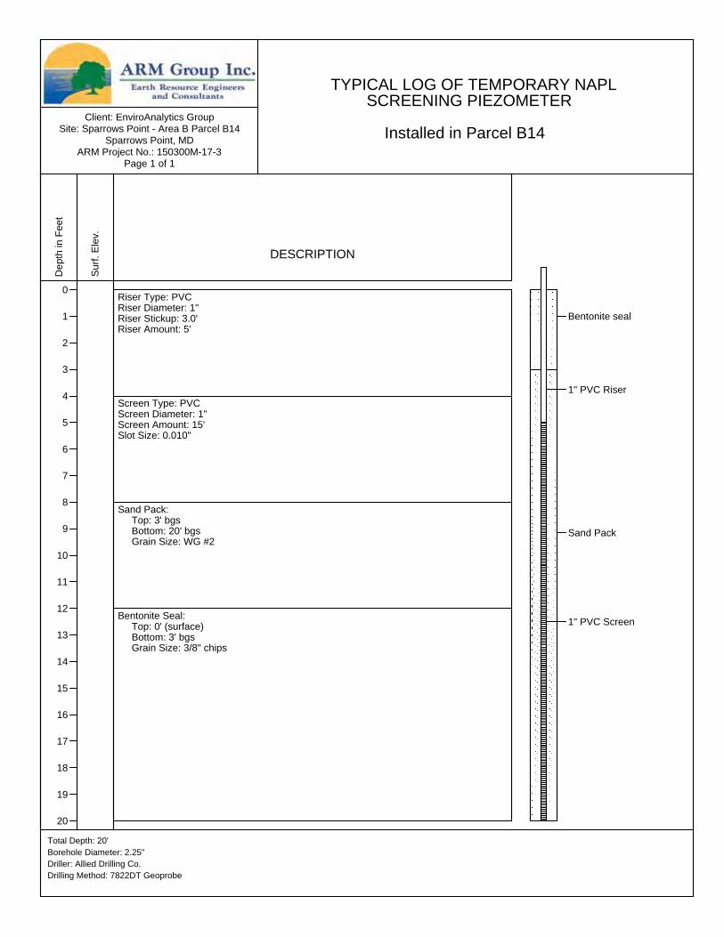
Client: EnviroAnalytics GroupSite: Sparrows Point - Area B Parcel B14
Sparrows Point, MDARM Project No.: 150300M-17-3
Page 1 of 1
Total Depth: 20'Borehole Diameter: 2.25"Driller: Allied Drilling Co.Drilling Method: 7822DT Geoprobe
Depth
in Fe
et
0
1
2
3
4
5
6
7
8
9
10
11
12
13
14
15
16
17
18
19
20
Surf.
Elev.
DESCRIPTION
Riser Type: PVCRiser Diameter: 1"Riser Stickup: 3.0'Riser Amount: 5'
Screen Type: PVCScreen Diameter: 1"Screen Amount: 15'Slot Size: 0.010"
Sand Pack: Top: 3' bgs Bottom: 20' bgs Grain Size: WG #2
Bentonite Seal: Top: 0' (surface) Bottom: 3' bgs Grain Size: 3/8" chips
Bentonite seal
Sand Pack
1" PVC Riser
1" PVC Screen
TYPICAL LOG OF TEMPORARY NAPL SCREENING PIEZOMETER Installed in Parcel B14

APPENDIX C
NAPL Gauging Summary Tables
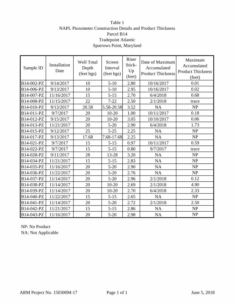
Table 1 NAPL Piezometer Construction Details and Product Thickness
Parcel B14Tradepoint Atlantic
Sparrows Point, Maryland
B14-002-PZ 9/14/2017 10 5-10 2.80 10/16/2017 0.01B14-006-PZ 9/13/2017 10 5-10 2.95 10/16/2017 0.02B14-007-PZ 11/16/2017 15 5-15 2.70 6/4/2018 0.68B14-008-PZ 11/15/2017 22 7-22 2.50 2/1/2018 traceB14-010-PZ 9/13/2017 20.58 5.58-20.58 3.52 NA NPB14-011-PZ 9/7/2017 20 10-20 1.00 10/11/2017 0.18B14-012-PZ 9/15/2017 20 10-20 3.05 10/10/2017 0.06B14-013-PZ 11/21/2017 20 5-20 2.90 6/4/2018 1.73B14-015-PZ 9/12/2017 25 5-25 2.25 NA NPB14-017-PZ 9/13/2017 17.68 7.68-17.68 2.25 NA NPB14-021-PZ 9/7/2017 15 5-15 0.97 10/11/2017 0.59B14-022-PZ 9/7/2017 15 5-15 0.80 9/7/2017 traceB14-028-PZ 9/11/2017 28 13-28 3.20 NA NPB14-034-PZ 11/21/2017 15 5-15 2.83 NA NPB14-035-PZ 11/16/2017 20 5-20 2.90 NA NPB14-036-PZ 11/22/2017 20 5-20 2.76 NA NPB14-037-PZ 11/14/2017 20 5-20 2.96 2/1/2018 0.12B14-038-PZ 11/14/2017 20 10-20 2.69 2/1/2018 4.90B14-039-PZ 11/14/2017 20 10-20 2.70 6/4/2018 2.33B14-040-PZ 11/22/2017 15 5-15 2.65 NA NPB14-041-PZ 11/14/2017 20 5-20 2.72 2/1/2018 2.50B14-042-PZ 11/21/2017 15 5-15 2.86 NA NPB14-043-PZ 11/16/2017 20 5-20 2.98 NA NP
NP: No ProductNA: Not Applicable
Maximum Accumulated
Product Thickness (feet)
Sample ID Installation Date
Well Total Depth
(feet bgs)
Screen Interval
(feet bgs)
RiserStick-
Up(feet)
Date of Maximum Accumulated
Product Thickness
ARM Project No. 150300M-17 Page 1 of 1 June 5, 2018
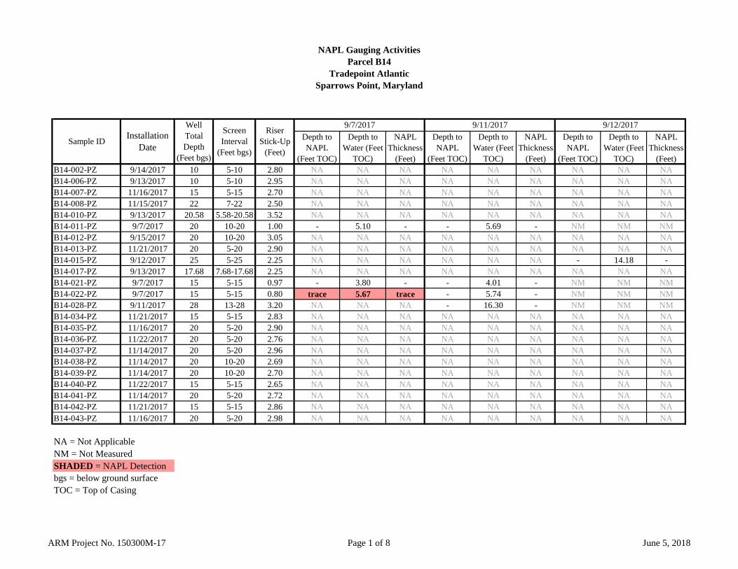
NAPL Gauging ActivitiesParcel B14
Tradepoint AtlanticSparrows Point, Maryland
Depth to NAPL
(Feet TOC)
Depth to Water (Feet
TOC)
NAPL Thickness
(Feet)
Depth to NAPL
(Feet TOC)
Depth to Water (Feet
TOC)
NAPL Thickness
(Feet)
Depth to NAPL
(Feet TOC)
Depth to Water (Feet
TOC)
NAPL Thickness
(Feet)B14-002-PZ 9/14/2017 10 5-10 2.80 NA NA NA NA NA NA NA NA NAB14-006-PZ 9/13/2017 10 5-10 2.95 NA NA NA NA NA NA NA NA NAB14-007-PZ 11/16/2017 15 5-15 2.70 NA NA NA NA NA NA NA NA NAB14-008-PZ 11/15/2017 22 7-22 2.50 NA NA NA NA NA NA NA NA NAB14-010-PZ 9/13/2017 20.58 5.58-20.58 3.52 NA NA NA NA NA NA NA NA NAB14-011-PZ 9/7/2017 20 10-20 1.00 - 5.10 - - 5.69 - NM NM NMB14-012-PZ 9/15/2017 20 10-20 3.05 NA NA NA NA NA NA NA NA NAB14-013-PZ 11/21/2017 20 5-20 2.90 NA NA NA NA NA NA NA NA NAB14-015-PZ 9/12/2017 25 5-25 2.25 NA NA NA NA NA NA - 14.18 -B14-017-PZ 9/13/2017 17.68 7.68-17.68 2.25 NA NA NA NA NA NA NA NA NAB14-021-PZ 9/7/2017 15 5-15 0.97 - 3.80 - - 4.01 - NM NM NMB14-022-PZ 9/7/2017 15 5-15 0.80 trace 5.67 trace - 5.74 - NM NM NMB14-028-PZ 9/11/2017 28 13-28 3.20 NA NA NA - 16.30 - NM NM NMB14-034-PZ 11/21/2017 15 5-15 2.83 NA NA NA NA NA NA NA NA NAB14-035-PZ 11/16/2017 20 5-20 2.90 NA NA NA NA NA NA NA NA NAB14-036-PZ 11/22/2017 20 5-20 2.76 NA NA NA NA NA NA NA NA NAB14-037-PZ 11/14/2017 20 5-20 2.96 NA NA NA NA NA NA NA NA NAB14-038-PZ 11/14/2017 20 10-20 2.69 NA NA NA NA NA NA NA NA NAB14-039-PZ 11/14/2017 20 10-20 2.70 NA NA NA NA NA NA NA NA NAB14-040-PZ 11/22/2017 15 5-15 2.65 NA NA NA NA NA NA NA NA NAB14-041-PZ 11/14/2017 20 5-20 2.72 NA NA NA NA NA NA NA NA NAB14-042-PZ 11/21/2017 15 5-15 2.86 NA NA NA NA NA NA NA NA NAB14-043-PZ 11/16/2017 20 5-20 2.98 NA NA NA NA NA NA NA NA NA
NA = Not ApplicableNM = Not MeasuredSHADED = NAPL Detectionbgs = below ground surfaceTOC = Top of Casing
9/7/2017 9/11/2017 9/12/2017
Sample ID Installation Date
Well Total Depth
(Feet bgs)
Screen Interval
(Feet bgs)
RiserStick-Up
(Feet)
ARM Project No. 150300M-17 Page 1 of 8 June 5, 2018
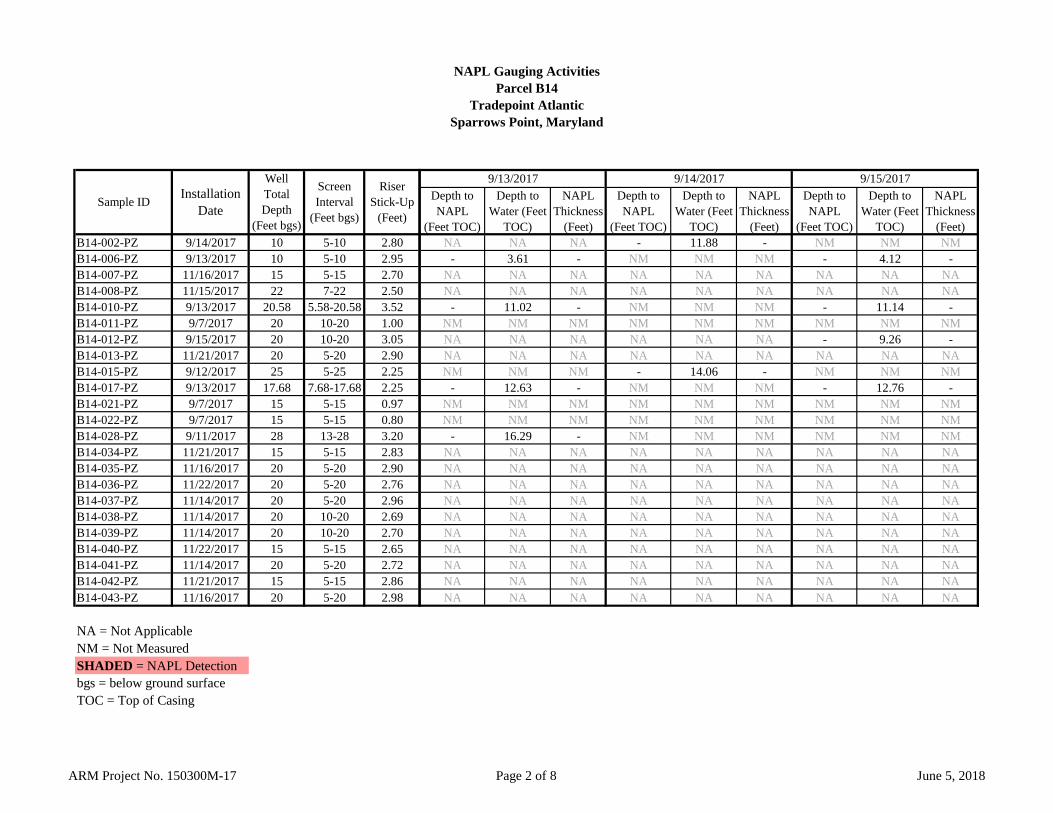
NAPL Gauging ActivitiesParcel B14
Tradepoint AtlanticSparrows Point, Maryland
B14-002-PZ 9/14/2017 10 5-10 2.80B14-006-PZ 9/13/2017 10 5-10 2.95B14-007-PZ 11/16/2017 15 5-15 2.70B14-008-PZ 11/15/2017 22 7-22 2.50B14-010-PZ 9/13/2017 20.58 5.58-20.58 3.52B14-011-PZ 9/7/2017 20 10-20 1.00B14-012-PZ 9/15/2017 20 10-20 3.05B14-013-PZ 11/21/2017 20 5-20 2.90B14-015-PZ 9/12/2017 25 5-25 2.25B14-017-PZ 9/13/2017 17.68 7.68-17.68 2.25B14-021-PZ 9/7/2017 15 5-15 0.97B14-022-PZ 9/7/2017 15 5-15 0.80B14-028-PZ 9/11/2017 28 13-28 3.20B14-034-PZ 11/21/2017 15 5-15 2.83B14-035-PZ 11/16/2017 20 5-20 2.90B14-036-PZ 11/22/2017 20 5-20 2.76B14-037-PZ 11/14/2017 20 5-20 2.96B14-038-PZ 11/14/2017 20 10-20 2.69B14-039-PZ 11/14/2017 20 10-20 2.70B14-040-PZ 11/22/2017 15 5-15 2.65B14-041-PZ 11/14/2017 20 5-20 2.72B14-042-PZ 11/21/2017 15 5-15 2.86B14-043-PZ 11/16/2017 20 5-20 2.98
NA = Not ApplicableNM = Not MeasuredSHADED = NAPL Detectionbgs = below ground surfaceTOC = Top of Casing
Sample ID Installation Date
Well Total Depth
(Feet bgs)
Screen Interval
(Feet bgs)
RiserStick-Up
(Feet)
Depth to NAPL
(Feet TOC)
Depth to Water (Feet
TOC)
NAPL Thickness
(Feet)
Depth to NAPL
(Feet TOC)
Depth to Water (Feet
TOC)
NAPL Thickness
(Feet)
Depth to NAPL
(Feet TOC)
Depth to Water (Feet
TOC)
NAPL Thickness
(Feet)NA NA NA - 11.88 - NM NM NM
- 3.61 - NM NM NM - 4.12 -NA NA NA NA NA NA NA NA NANA NA NA NA NA NA NA NA NA
- 11.02 - NM NM NM - 11.14 -NM NM NM NM NM NM NM NM NMNA NA NA NA NA NA - 9.26 -NA NA NA NA NA NA NA NA NANM NM NM - 14.06 - NM NM NM
- 12.63 - NM NM NM - 12.76 -NM NM NM NM NM NM NM NM NMNM NM NM NM NM NM NM NM NM
- 16.29 - NM NM NM NM NM NMNA NA NA NA NA NA NA NA NANA NA NA NA NA NA NA NA NANA NA NA NA NA NA NA NA NANA NA NA NA NA NA NA NA NANA NA NA NA NA NA NA NA NANA NA NA NA NA NA NA NA NANA NA NA NA NA NA NA NA NANA NA NA NA NA NA NA NA NANA NA NA NA NA NA NA NA NANA NA NA NA NA NA NA NA NA
9/13/2017 9/14/2017 9/15/2017
ARM Project No. 150300M-17 Page 2 of 8 June 5, 2018
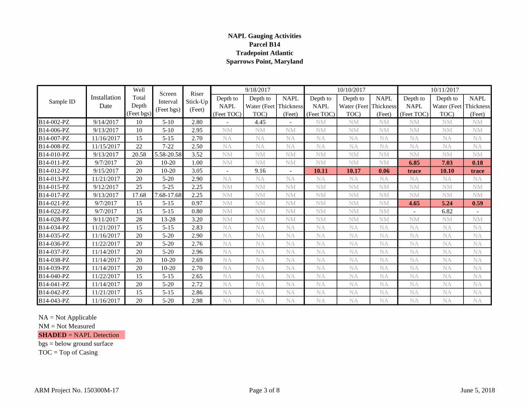
NAPL Gauging ActivitiesParcel B14
Tradepoint AtlanticSparrows Point, Maryland
B14-002-PZ 9/14/2017 10 5-10 2.80B14-006-PZ 9/13/2017 10 5-10 2.95B14-007-PZ 11/16/2017 15 5-15 2.70B14-008-PZ 11/15/2017 22 7-22 2.50B14-010-PZ 9/13/2017 20.58 5.58-20.58 3.52B14-011-PZ 9/7/2017 20 10-20 1.00B14-012-PZ 9/15/2017 20 10-20 3.05B14-013-PZ 11/21/2017 20 5-20 2.90B14-015-PZ 9/12/2017 25 5-25 2.25B14-017-PZ 9/13/2017 17.68 7.68-17.68 2.25B14-021-PZ 9/7/2017 15 5-15 0.97B14-022-PZ 9/7/2017 15 5-15 0.80B14-028-PZ 9/11/2017 28 13-28 3.20B14-034-PZ 11/21/2017 15 5-15 2.83B14-035-PZ 11/16/2017 20 5-20 2.90B14-036-PZ 11/22/2017 20 5-20 2.76B14-037-PZ 11/14/2017 20 5-20 2.96B14-038-PZ 11/14/2017 20 10-20 2.69B14-039-PZ 11/14/2017 20 10-20 2.70B14-040-PZ 11/22/2017 15 5-15 2.65B14-041-PZ 11/14/2017 20 5-20 2.72B14-042-PZ 11/21/2017 15 5-15 2.86B14-043-PZ 11/16/2017 20 5-20 2.98
NA = Not ApplicableNM = Not MeasuredSHADED = NAPL Detectionbgs = below ground surfaceTOC = Top of Casing
Sample ID Installation Date
Well Total Depth
(Feet bgs)
Screen Interval
(Feet bgs)
RiserStick-Up
(Feet)
Depth to NAPL
(Feet TOC)
Depth to Water (Feet
TOC)
NAPL Thickness
(Feet)
Depth to NAPL
(Feet TOC)
Depth to Water (Feet
TOC)
NAPL Thickness
(Feet)
Depth to NAPL
(Feet TOC)
Depth to Water (Feet
TOC)
NAPL Thickness
(Feet)- 4.45 - NM NM NM NM NM NM
NM NM NM NM NM NM NM NM NMNA NA NA NA NA NA NA NA NANA NA NA NA NA NA NA NA NANM NM NM NM NM NM NM NM NMNM NM NM NM NM NM 6.85 7.03 0.18
- 9.16 - 10.11 10.17 0.06 trace 10.10 traceNA NA NA NA NA NA NA NA NANM NM NM NM NM NM NM NM NMNM NM NM NM NM NM NM NM NMNM NM NM NM NM NM 4.65 5.24 0.59NM NM NM NM NM NM - 6.82 -NM NM NM NM NM NM NM NM NMNA NA NA NA NA NA NA NA NANA NA NA NA NA NA NA NA NANA NA NA NA NA NA NA NA NANA NA NA NA NA NA NA NA NANA NA NA NA NA NA NA NA NANA NA NA NA NA NA NA NA NANA NA NA NA NA NA NA NA NANA NA NA NA NA NA NA NA NANA NA NA NA NA NA NA NA NANA NA NA NA NA NA NA NA NA
10/10/20179/18/2017 10/11/2017
ARM Project No. 150300M-17 Page 3 of 8 June 5, 2018
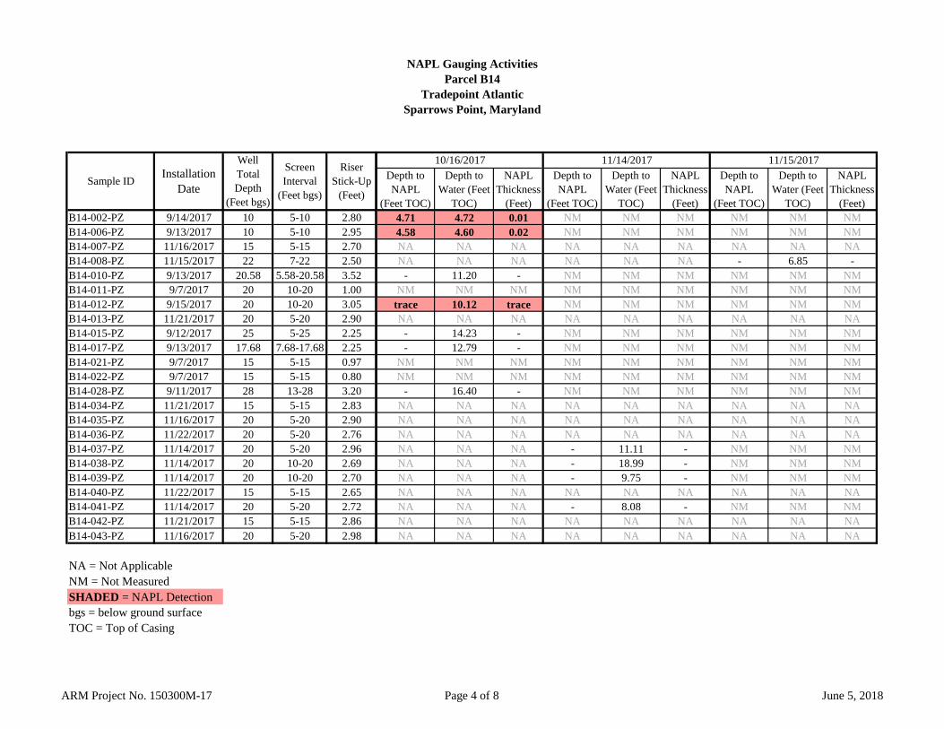
NAPL Gauging ActivitiesParcel B14
Tradepoint AtlanticSparrows Point, Maryland
B14-002-PZ 9/14/2017 10 5-10 2.80B14-006-PZ 9/13/2017 10 5-10 2.95B14-007-PZ 11/16/2017 15 5-15 2.70B14-008-PZ 11/15/2017 22 7-22 2.50B14-010-PZ 9/13/2017 20.58 5.58-20.58 3.52B14-011-PZ 9/7/2017 20 10-20 1.00B14-012-PZ 9/15/2017 20 10-20 3.05B14-013-PZ 11/21/2017 20 5-20 2.90B14-015-PZ 9/12/2017 25 5-25 2.25B14-017-PZ 9/13/2017 17.68 7.68-17.68 2.25B14-021-PZ 9/7/2017 15 5-15 0.97B14-022-PZ 9/7/2017 15 5-15 0.80B14-028-PZ 9/11/2017 28 13-28 3.20B14-034-PZ 11/21/2017 15 5-15 2.83B14-035-PZ 11/16/2017 20 5-20 2.90B14-036-PZ 11/22/2017 20 5-20 2.76B14-037-PZ 11/14/2017 20 5-20 2.96B14-038-PZ 11/14/2017 20 10-20 2.69B14-039-PZ 11/14/2017 20 10-20 2.70B14-040-PZ 11/22/2017 15 5-15 2.65B14-041-PZ 11/14/2017 20 5-20 2.72B14-042-PZ 11/21/2017 15 5-15 2.86B14-043-PZ 11/16/2017 20 5-20 2.98
NA = Not ApplicableNM = Not MeasuredSHADED = NAPL Detectionbgs = below ground surfaceTOC = Top of Casing
Sample ID Installation Date
Well Total Depth
(Feet bgs)
Screen Interval
(Feet bgs)
RiserStick-Up
(Feet)
Depth to NAPL
(Feet TOC)
Depth to Water (Feet
TOC)
NAPL Thickness
(Feet)
Depth to NAPL
(Feet TOC)
Depth to Water (Feet
TOC)
NAPL Thickness
(Feet)
Depth to NAPL
(Feet TOC)
Depth to Water (Feet
TOC)
NAPL Thickness
(Feet)4.71 4.72 0.01 NM NM NM NM NM NM4.58 4.60 0.02 NM NM NM NM NM NMNA NA NA NA NA NA NA NA NANA NA NA NA NA NA - 6.85 -
- 11.20 - NM NM NM NM NM NMNM NM NM NM NM NM NM NM NM
trace 10.12 trace NM NM NM NM NM NMNA NA NA NA NA NA NA NA NA
- 14.23 - NM NM NM NM NM NM- 12.79 - NM NM NM NM NM NM
NM NM NM NM NM NM NM NM NMNM NM NM NM NM NM NM NM NM
- 16.40 - NM NM NM NM NM NMNA NA NA NA NA NA NA NA NANA NA NA NA NA NA NA NA NANA NA NA NA NA NA NA NA NANA NA NA - 11.11 - NM NM NMNA NA NA - 18.99 - NM NM NMNA NA NA - 9.75 - NM NM NMNA NA NA NA NA NA NA NA NANA NA NA - 8.08 - NM NM NMNA NA NA NA NA NA NA NA NANA NA NA NA NA NA NA NA NA
11/14/201710/16/2017 11/15/2017
ARM Project No. 150300M-17 Page 4 of 8 June 5, 2018
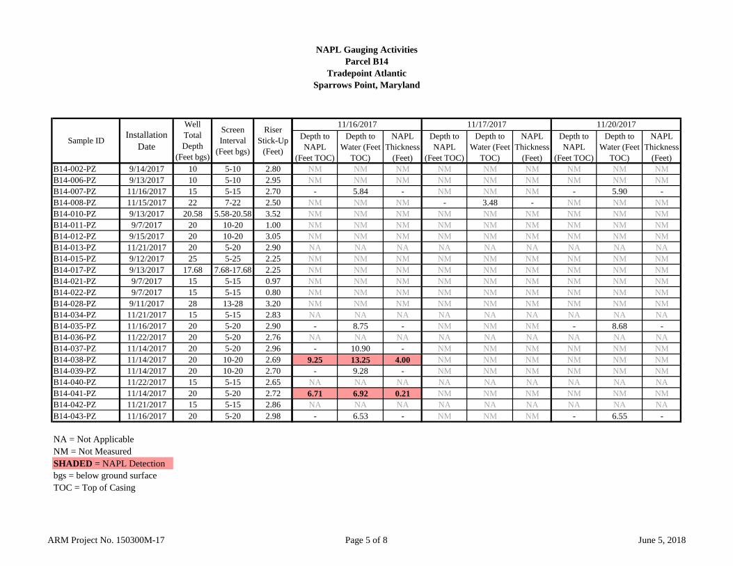
NAPL Gauging ActivitiesParcel B14
Tradepoint AtlanticSparrows Point, Maryland
B14-002-PZ 9/14/2017 10 5-10 2.80B14-006-PZ 9/13/2017 10 5-10 2.95B14-007-PZ 11/16/2017 15 5-15 2.70B14-008-PZ 11/15/2017 22 7-22 2.50B14-010-PZ 9/13/2017 20.58 5.58-20.58 3.52B14-011-PZ 9/7/2017 20 10-20 1.00B14-012-PZ 9/15/2017 20 10-20 3.05B14-013-PZ 11/21/2017 20 5-20 2.90B14-015-PZ 9/12/2017 25 5-25 2.25B14-017-PZ 9/13/2017 17.68 7.68-17.68 2.25B14-021-PZ 9/7/2017 15 5-15 0.97B14-022-PZ 9/7/2017 15 5-15 0.80B14-028-PZ 9/11/2017 28 13-28 3.20B14-034-PZ 11/21/2017 15 5-15 2.83B14-035-PZ 11/16/2017 20 5-20 2.90B14-036-PZ 11/22/2017 20 5-20 2.76B14-037-PZ 11/14/2017 20 5-20 2.96B14-038-PZ 11/14/2017 20 10-20 2.69B14-039-PZ 11/14/2017 20 10-20 2.70B14-040-PZ 11/22/2017 15 5-15 2.65B14-041-PZ 11/14/2017 20 5-20 2.72B14-042-PZ 11/21/2017 15 5-15 2.86B14-043-PZ 11/16/2017 20 5-20 2.98
NA = Not ApplicableNM = Not MeasuredSHADED = NAPL Detectionbgs = below ground surfaceTOC = Top of Casing
Sample ID Installation Date
Well Total Depth
(Feet bgs)
Screen Interval
(Feet bgs)
RiserStick-Up
(Feet)
Depth to NAPL
(Feet TOC)
Depth to Water (Feet
TOC)
NAPL Thickness
(Feet)
Depth to NAPL
(Feet TOC)
Depth to Water (Feet
TOC)
NAPL Thickness
(Feet)
Depth to NAPL
(Feet TOC)
Depth to Water (Feet
TOC)
NAPL Thickness
(Feet)NM NM NM NM NM NM NM NM NMNM NM NM NM NM NM NM NM NM
- 5.84 - NM NM NM - 5.90 -NM NM NM - 3.48 - NM NM NMNM NM NM NM NM NM NM NM NMNM NM NM NM NM NM NM NM NMNM NM NM NM NM NM NM NM NMNA NA NA NA NA NA NA NA NANM NM NM NM NM NM NM NM NMNM NM NM NM NM NM NM NM NMNM NM NM NM NM NM NM NM NMNM NM NM NM NM NM NM NM NMNM NM NM NM NM NM NM NM NMNA NA NA NA NA NA NA NA NA
- 8.75 - NM NM NM - 8.68 -NA NA NA NA NA NA NA NA NA
- 10.90 - NM NM NM NM NM NM9.25 13.25 4.00 NM NM NM NM NM NM
- 9.28 - NM NM NM NM NM NMNA NA NA NA NA NA NA NA NA6.71 6.92 0.21 NM NM NM NM NM NMNA NA NA NA NA NA NA NA NA
- 6.53 - NM NM NM - 6.55 -
11/16/2017 11/17/2017 11/20/2017
ARM Project No. 150300M-17 Page 5 of 8 June 5, 2018
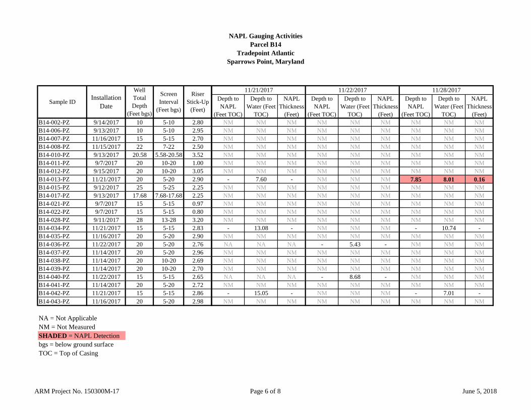
NAPL Gauging ActivitiesParcel B14
Tradepoint AtlanticSparrows Point, Maryland
B14-002-PZ 9/14/2017 10 5-10 2.80B14-006-PZ 9/13/2017 10 5-10 2.95B14-007-PZ 11/16/2017 15 5-15 2.70B14-008-PZ 11/15/2017 22 7-22 2.50B14-010-PZ 9/13/2017 20.58 5.58-20.58 3.52B14-011-PZ 9/7/2017 20 10-20 1.00B14-012-PZ 9/15/2017 20 10-20 3.05B14-013-PZ 11/21/2017 20 5-20 2.90B14-015-PZ 9/12/2017 25 5-25 2.25B14-017-PZ 9/13/2017 17.68 7.68-17.68 2.25B14-021-PZ 9/7/2017 15 5-15 0.97B14-022-PZ 9/7/2017 15 5-15 0.80B14-028-PZ 9/11/2017 28 13-28 3.20B14-034-PZ 11/21/2017 15 5-15 2.83B14-035-PZ 11/16/2017 20 5-20 2.90B14-036-PZ 11/22/2017 20 5-20 2.76B14-037-PZ 11/14/2017 20 5-20 2.96B14-038-PZ 11/14/2017 20 10-20 2.69B14-039-PZ 11/14/2017 20 10-20 2.70B14-040-PZ 11/22/2017 15 5-15 2.65B14-041-PZ 11/14/2017 20 5-20 2.72B14-042-PZ 11/21/2017 15 5-15 2.86B14-043-PZ 11/16/2017 20 5-20 2.98
NA = Not ApplicableNM = Not MeasuredSHADED = NAPL Detectionbgs = below ground surfaceTOC = Top of Casing
Sample ID Installation Date
Well Total Depth
(Feet bgs)
Screen Interval
(Feet bgs)
RiserStick-Up
(Feet)
Depth to NAPL
(Feet TOC)
Depth to Water (Feet
TOC)
NAPL Thickness
(Feet)
Depth to NAPL
(Feet TOC)
Depth to Water (Feet
TOC)
NAPL Thickness
(Feet)
Depth to NAPL
(Feet TOC)
Depth to Water (Feet
TOC)
NAPL Thickness
(Feet)NM NM NM NM NM NM NM NM NMNM NM NM NM NM NM NM NM NMNM NM NM NM NM NM NM NM NMNM NM NM NM NM NM NM NM NMNM NM NM NM NM NM NM NM NMNM NM NM NM NM NM NM NM NMNM NM NM NM NM NM NM NM NM
- 7.60 - NM NM NM 7.85 8.01 0.16NM NM NM NM NM NM NM NM NMNM NM NM NM NM NM NM NM NMNM NM NM NM NM NM NM NM NMNM NM NM NM NM NM NM NM NMNM NM NM NM NM NM NM NM NM
- 13.08 - NM NM NM - 10.74 -NM NM NM NM NM NM NM NM NMNA NA NA - 5.43 - NM NM NMNM NM NM NM NM NM NM NM NMNM NM NM NM NM NM NM NM NMNM NM NM NM NM NM NM NM NMNA NA NA - 8.68 - NM NM NMNM NM NM NM NM NM NM NM NM
- 15.05 - NM NM NM - 7.01 -NM NM NM NM NM NM NM NM NM
11/21/2017 11/28/201711/22/2017
ARM Project No. 150300M-17 Page 6 of 8 June 5, 2018

NAPL Gauging ActivitiesParcel B14
Tradepoint AtlanticSparrows Point, Maryland
B14-002-PZ 9/14/2017 10 5-10 2.80B14-006-PZ 9/13/2017 10 5-10 2.95B14-007-PZ 11/16/2017 15 5-15 2.70B14-008-PZ 11/15/2017 22 7-22 2.50B14-010-PZ 9/13/2017 20.58 5.58-20.58 3.52B14-011-PZ 9/7/2017 20 10-20 1.00B14-012-PZ 9/15/2017 20 10-20 3.05B14-013-PZ 11/21/2017 20 5-20 2.90B14-015-PZ 9/12/2017 25 5-25 2.25B14-017-PZ 9/13/2017 17.68 7.68-17.68 2.25B14-021-PZ 9/7/2017 15 5-15 0.97B14-022-PZ 9/7/2017 15 5-15 0.80B14-028-PZ 9/11/2017 28 13-28 3.20B14-034-PZ 11/21/2017 15 5-15 2.83B14-035-PZ 11/16/2017 20 5-20 2.90B14-036-PZ 11/22/2017 20 5-20 2.76B14-037-PZ 11/14/2017 20 5-20 2.96B14-038-PZ 11/14/2017 20 10-20 2.69B14-039-PZ 11/14/2017 20 10-20 2.70B14-040-PZ 11/22/2017 15 5-15 2.65B14-041-PZ 11/14/2017 20 5-20 2.72B14-042-PZ 11/21/2017 15 5-15 2.86B14-043-PZ 11/16/2017 20 5-20 2.98
NA = Not ApplicableNM = Not MeasuredSHADED = NAPL Detectionbgs = below ground surfaceTOC = Top of Casing
Sample ID Installation Date
Well Total Depth
(Feet bgs)
Screen Interval
(Feet bgs)
RiserStick-Up
(Feet)
Depth to NAPL
(Feet TOC)
Depth to Water (Feet
TOC)
NAPL Thickness
(Feet)
Depth to NAPL
(Feet TOC)
Depth to Water (Feet
TOC)
NAPL Thickness
(Feet)
Depth to NAPL
(Feet TOC)
Depth to Water (Feet
TOC)
NAPL Thickness
(Feet)NM NM NM NM NM NM NM NM NMNM NM NM NM NM NM NM NM NMNM NM NM NM NM NM NM NM NMNM NM NM NM NM NM NM NM NMNM NM NM NM NM NM NM NM NMNM NM NM NM NM NM NM NM NMNM NM NM NM NM NM NM NM NMNM NM NM 7.45 7.76 0.31 NM NM NMNM NM NM NM NM NM NM NM NMNM NM NM NM NM NM NM NM NMNM NM NM NM NM NM NM NM NMNM NM NM NM NM NM NM NM NMNM NM NM NM NM NM NM NM NMNM NM NM - 11.11 - NM NM NMNM NM NM NM NM NM NM NM NM
- 5.60 - NM NM NM - 5.22 -NM NM NM NM NM NM NM NM NMNM NM NM NM NM NM NM NM NMNM NM NM NM NM NM NM NM NM
- 8.73 - NM NM NM - 8.84 -NM NM NM NM NM NM NM NM NMNM NM NM - 7.03 - NM NM NMNM NM NM - 6.75 - NM NM NM
1/4/201812/21/201711/29/2017
ARM Project No. 150300M-17 Page 7 of 8 June 5, 2018
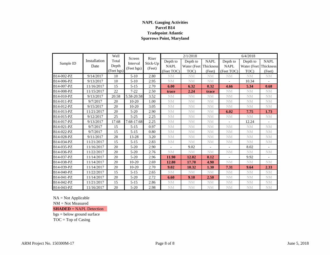
NAPL Gauging ActivitiesParcel B14
Tradepoint AtlanticSparrows Point, Maryland
B14-002-PZ 9/14/2017 10 5-10 2.80B14-006-PZ 9/13/2017 10 5-10 2.95B14-007-PZ 11/16/2017 15 5-15 2.70B14-008-PZ 11/15/2017 22 7-22 2.50B14-010-PZ 9/13/2017 20.58 5.58-20.58 3.52B14-011-PZ 9/7/2017 20 10-20 1.00B14-012-PZ 9/15/2017 20 10-20 3.05B14-013-PZ 11/21/2017 20 5-20 2.90B14-015-PZ 9/12/2017 25 5-25 2.25B14-017-PZ 9/13/2017 17.68 7.68-17.68 2.25B14-021-PZ 9/7/2017 15 5-15 0.97B14-022-PZ 9/7/2017 15 5-15 0.80B14-028-PZ 9/11/2017 28 13-28 3.20B14-034-PZ 11/21/2017 15 5-15 2.83B14-035-PZ 11/16/2017 20 5-20 2.90B14-036-PZ 11/22/2017 20 5-20 2.76B14-037-PZ 11/14/2017 20 5-20 2.96B14-038-PZ 11/14/2017 20 10-20 2.69B14-039-PZ 11/14/2017 20 10-20 2.70B14-040-PZ 11/22/2017 15 5-15 2.65B14-041-PZ 11/14/2017 20 5-20 2.72B14-042-PZ 11/21/2017 15 5-15 2.86B14-043-PZ 11/16/2017 20 5-20 2.98
NA = Not ApplicableNM = Not MeasuredSHADED = NAPL Detectionbgs = below ground surfaceTOC = Top of Casing
Sample ID Installation Date
Well Total Depth
(Feet bgs)
Screen Interval
(Feet bgs)
RiserStick-Up
(Feet)
Depth to NAPL
(Feet TOC)
Depth to Water (Feet
TOC)
NAPL Thickness
(Feet)
Depth to NAPL
(Feet TOC)
Depth to Water (Feet
TOC)
NAPL Thickness
(Feet)NM NM NM NM NM NMNM NM NM - 10.34 -6.00 6.32 0.32 4.66 5.34 0.68trace 2.24 trace NM NM NMNM NM NM NM NM NMNM NM NM NM NM NMNM NM NM NM NM NMNM NM NM 6.02 7.75 1.73NM NM NM NM NM NMNM NM NM - 12.24 -NM NM NM NM NM NMNM NM NM NM NM NMNM NM NM NM NM NMNM NM NM NM NM NM
- 9.02 - - 8.02 -NM NM NM NM NM NM
11.90 12.02 0.12 - 9.92 -12.80 17.70 4.90 NM NM NM9.02 10.32 1.30 7.31 9.64 2.33NM NM NM NM NM NM6.60 9.10 2.50 NM NM NMNM NM NM NM NM NMNM NM NM NM NM NM
6/4/20182/1/2018
ARM Project No. 150300M-17 Page 8 of 8 June 5, 2018

APPENDIX D
Geotechnical Boring Logs
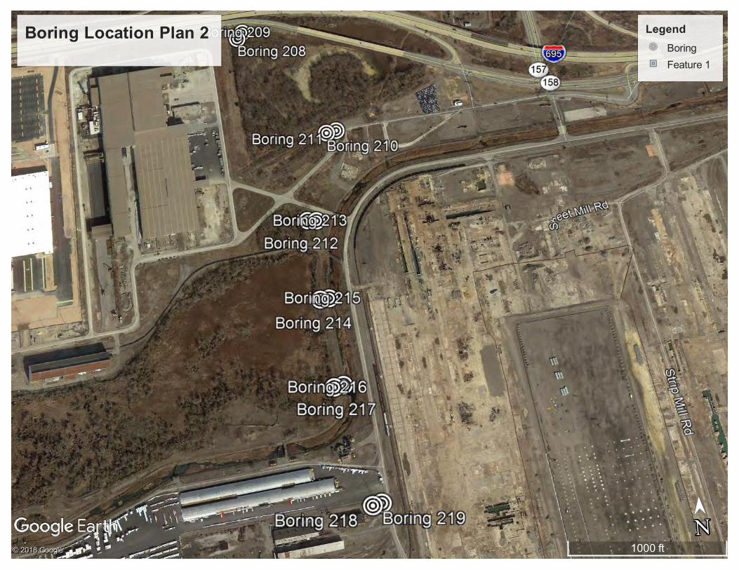
Boring Location Plan 2 Legend
Boring
Feature 1
1000 ft
N
➤➤
N© 2018 Google
© 2018 Google
© 2018 Google

Project: S18032 Fitzell Substation In Situ
HILLIS-CARNES
Engineering Associates, Inc.
417 Maryland Avenue, Delmar, MD 21875
http://www.hcea.com
Total depth: 70.34 ft, Date: 3/8/2018
Surface Elevation: 8.00 ft
Sparrows Point, Maryland
Coords: X:0.00, Y:0.00
Cone Type: NOVA U2
Cone Operator: R. Harman
CPT: Fitzell Project B-214
Location:
Norm. cone resistance
Qtn4003002001000
Depth
(ft
)
70
68
66
64
62
60
58
56
54
52
50
48
46
44
42
40
38
36
34
32
30
28
26
24
22
20
18
16
14
12
10
8
6
4
2
0
Norm. cone resistance Norm. pore pressure ratio
Bq10 .80 .60.40.20-0.2
Depth
(ft
)
70
68
66
64
62
60
58
56
54
52
50
48
46
44
42
40
38
36
34
32
30
28
26
24
22
20
18
16
14
12
10
8
6
4
2
0
Norm. pore pressure ratioNorm. friction ratio
Fr (%)1086420
Depth
(ft
)
70
68
66
64
62
60
58
56
54
52
50
48
46
44
42
40
38
36
34
32
30
28
26
24
22
20
18
16
14
12
10
8
6
4
2
0
Norm. friction ratio SBTn Index
Ic4321
Depth
(ft
)70
68
66
64
62
60
58
56
54
52
50
48
46
44
42
40
38
36
34
32
30
28
26
24
22
20
18
16
14
12
10
8
6
4
2
0
SBTn Index Norm. Soil Behaviour Type
SBTn (Robertson, 1990)181614121086420
Depth
(ft
)
70
68
66
64
62
60
58
56
54
52
50
48
46
44
42
40
38
36
34
32
30
28
26
24
22
20
18
16
14
12
10
8
6
4
2
0Norm. Soil Behaviour Type
Sand & silty sandClay & silty clay
Sand & silty sandSilty sand & sandy silt
ClayOrganic soilClay & silty clay
Organic soil
Clay
Clay & silty clay
Silty sand & sandy silt
Silty sand & sandy siltOrganic soil
Clay
Clay & silty clay
Clay & silty clay
Sand & silty sandSand & silty sand
Sand & silty sand
Silty sand & sandy silt
Sand & silty sand
Silty sand & sandy silt
Sand & silty sand
Sand & silty sand
Silty sand & sandy silt
Silty sand & sandy siltSilty sand & sandy siltSand & silty sand
Silty sand & sandy silt
Sand & silty sand
SBTn legend
1. Sensitive fine grained
2. Organic material
3. Clay to silty clay
4. Clayey silt to silty clay
5. Silty sand to sandy silt
6. Clean sand to silty sand
7. Gravely sand to sand
8. Very stiff sand to clayey sand
9. Very stiff fine grained
CPeT-IT v.2.0.2.5 - CPTU data presentation & interpretation software - Report created on: 3/9/2018, 3:47:55 PM 97
Project file: C:\Users\fernando_garcia\Desktop\Fitzell Project\Fitzell Project CPT Analyses.cpt
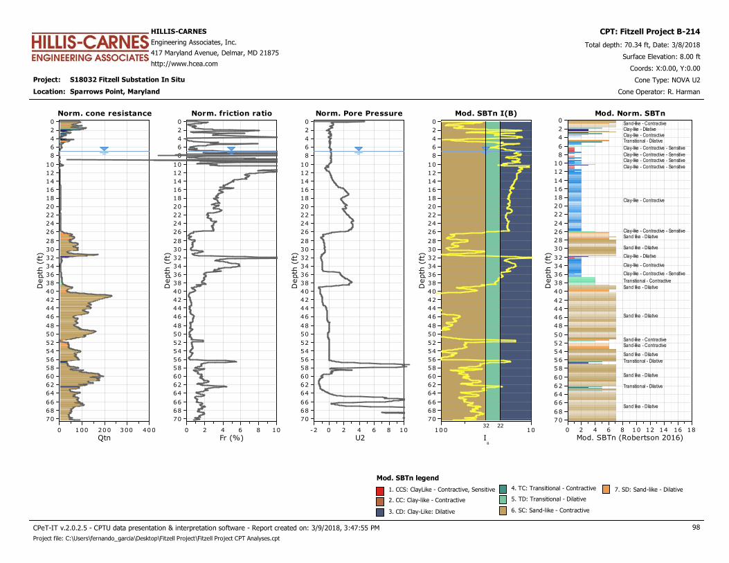
Project: S18032 Fitzell Substation In Situ
HILLIS-CARNES
Engineering Associates, Inc.
417 Maryland Avenue, Delmar, MD 21875
http://www.hcea.com
Total depth: 70.34 ft, Date: 3/8/2018
Surface Elevation: 8.00 ft
Sparrows Point, Maryland
Coords: X:0.00, Y:0.00
Cone Type: NOVA U2
Cone Operator: R. Harman
CPT: Fitzell Project B-214
Location:
Norm. cone resistance
Qtn4003002001000
Depth
(ft
)
70
68
66
64
62
60
58
56
54
52
50
48
46
44
42
40
38
36
34
32
30
28
26
24
22
20
18
16
14
12
10
8
6
4
2
0
Norm. cone resistance Norm. Pore Pressure
U21086420-2
Depth
(ft
)
70
68
66
64
62
60
58
56
54
52
50
48
46
44
42
40
38
36
34
32
30
28
26
24
22
20
18
16
14
12
10
8
6
4
2
0
Norm. Pore PressureNorm. friction ratio
Fr (%)1086420
Depth
(ft
)
70
68
66
64
62
60
58
56
54
52
50
48
46
44
42
40
38
36
34
32
30
28
26
24
22
20
18
16
14
12
10
8
6
4
2
0
Norm. friction ratio Mod. SBTn I(B)
IB
10100
Depth
(ft
)70
68
66
64
62
60
58
56
54
52
50
48
46
44
42
40
38
36
34
32
30
28
26
24
22
20
18
16
14
12
10
8
6
4
2
0
Mod. SBTn I(B)
2232
Mod. Norm. SBTn
Mod. SBTn (Robertson 2016)181614121086420
Depth
(ft
)
70
68
66
64
62
60
58
56
54
52
50
48
46
44
42
40
38
36
34
32
30
28
26
24
22
20
18
16
14
12
10
8
6
4
2
0Mod. Norm. SBTn
Sand-like - ContractiveClay-like - DilativeClay-like - ContractiveTransitional - Dilative
Clay-like - Contractive - Sensitive
Clay-like - Contractive - SensitiveClay-like - Contractive - Sensitive
Clay-like - Contractive - Sensitive
Clay-like - Contractive
Clay-like - Contractive - SensitiveSand like - Dilative
Sand like - Dilative
Clay-like - Dilative
Clay-like - Contractive
Clay-like - Contractive - Sensitive
Transitional - Contractive
Sand like - Dilative
Sand like - Dilative
Sand-like - ContractiveSand-like - Contractive
Sand like - Dilative
Transitional - Dilative
Sand like - Dilative
Transitional - Dilative
Sand like - Dilative
Mod. SBTn legend
1. CCS: ClayLike - Contractive, Sensitive
2. CC: Clay-like - Contractive
3. CD: Clay-Like: Dilative
4. TC: Transitional - Contractive
5. TD: Transitional - Dilative
6. SC: Sand-like - Contractive
7. SD: Sand-like - Dilative
CPeT-IT v.2.0.2.5 - CPTU data presentation & interpretation software - Report created on: 3/9/2018, 3:47:55 PM 98
Project file: C:\Users\fernando_garcia\Desktop\Fitzell Project\Fitzell Project CPT Analyses.cpt
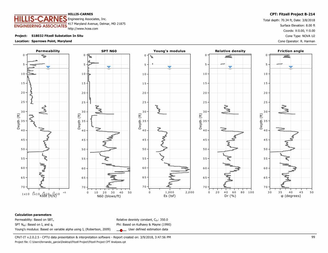
Project: S18032 Fitzell Substation In Situ
HILLIS-CARNES
Engineering Associates, Inc.
417 Maryland Avenue, Delmar, MD 21875
http://www.hcea.com
Total depth: 70.34 ft, Date: 3/8/2018
Surface Elevation: 8.00 ft
Sparrows Point, Maryland
Coords: X:0.00, Y:0.00
Cone Type: NOVA U2
Cone Operator: R. Harman
CPT: Fitzell Project B-214
Location:
Permeability
Ksbt (ft/s)1x10
-91x10
-61x10
-31x10
+0
Depth
(ft
)
70
65
60
55
50
45
40
35
30
25
20
15
10
5
0
Permeability Young's modulus
Es (tsf)2 ,0001 ,0000
Depth
(ft
)
70
65
60
55
50
45
40
35
30
25
20
15
10
5
0
Young's modulusSPT N60
N60 (blows/ft)50403020100
Depth
(ft
)
70
65
60
55
50
45
40
35
30
25
20
15
10
5
0
SPT N60 Relative density
Dr (%)100806040200
Depth
(ft
)
70
65
60
55
50
45
40
35
30
25
20
15
10
5
0
Relative density
Calculation parameters
Relative desnisty constant, CDr: 350.0Permeability: Based on SBTn
SPT N60: Based on Ic and qt
Young’s modulus: Based on variable alpha using Ic (Robertson, 2009)
Phi: Based on Kulhawy & Mayne (1990)
User defined estimation data
Friction angle
φ (degrees)5045403530
Depth
(ft
)
70
65
60
55
50
45
40
35
30
25
20
15
10
5
0
Friction angle
CPeT-IT v.2.0.2.5 - CPTU data presentation & interpretation software - Report created on: 3/9/2018, 3:47:56 PM 99
Project file: C:\Users\fernando_garcia\Desktop\Fitzell Project\Fitzell Project CPT Analyses.cpt

Project: S18032 Fitzell Substation In Situ
HILLIS-CARNES
Engineering Associates, Inc.
417 Maryland Avenue, Delmar, MD 21875
http://www.hcea.com
Total depth: 70.34 ft, Date: 3/8/2018
Surface Elevation: 8.00 ft
Sparrows Point, Maryland
Coords: X:0.00, Y:0.00
Cone Type: NOVA U2
Cone Operator: R. Harman
CPT: Fitzell Project B-214
Location:
Constrained Modulus
M(CPT) (tsf)2,0000
Depth
(ft
)
70
65
60
55
50
45
40
35
30
25
20
15
10
5
0
Constrained Modulus Shear strength
Su (tsf)50
Depth
(ft
)
62
60
58
56
54
52
50
48
46
44
42
40
38
36
34
32
30
28
26
24
22
20
18
16
14
12
10
8
6
4
2Su peak
Su remolded
Shear strengthShear modulus
Go (tsf)2,0000
Depth
(ft
)
70
65
60
55
50
45
40
35
30
25
20
15
10
5
0
Shear modulus Undrained strength ratio
Su/σ',v43210
Depth
(ft
)
62
60
58
56
54
52
50
48
46
44
42
40
38
36
34
32
30
28
26
24
22
20
18
16
14
12
10
8
6
4
2
Undrained strength ratio OCR
OCR20151050
Depth
(ft
)
62
60
58
56
54
52
50
48
46
44
42
40
38
36
34
32
30
28
26
24
22
20
18
16
14
12
10
8
6
4
2
OCR
Calculation parameters
Undrained shear strength cone factor for clays, Nkt: 14
OCR factor for clays, Nkt: 0.33
Go: Based on variable alpha using Ic (Robertson, 2009)
Constrained modulus: Based on variable alpha using Ic and Qtn (Robertson, 2009)
User defined estimation data
Flat Dilatometer Test data
CPeT-IT v.2.0.2.5 - CPTU data presentation & interpretation software - Report created on: 3/9/2018, 3:47:56 PM 100
Project file: C:\Users\fernando_garcia\Desktop\Fitzell Project\Fitzell Project CPT Analyses.cpt
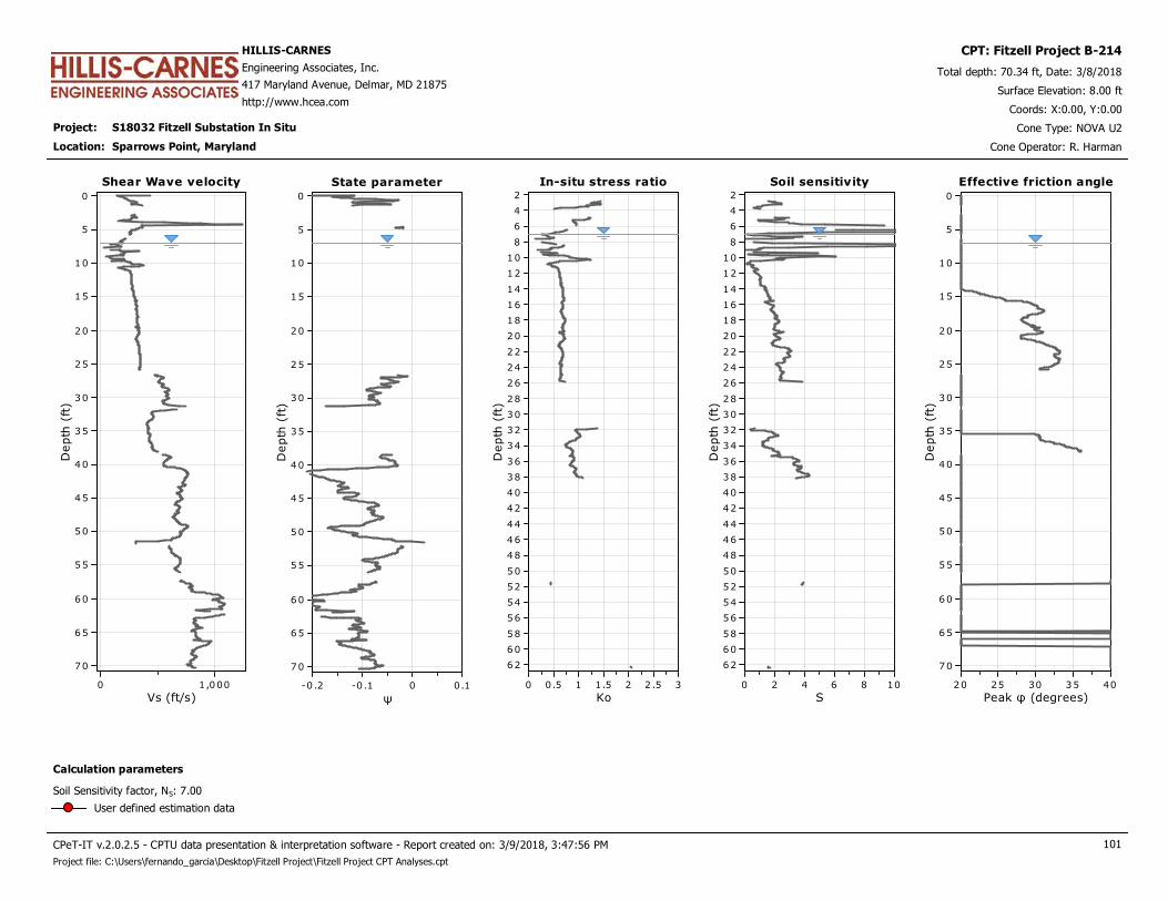
Project: S18032 Fitzell Substation In Situ
HILLIS-CARNES
Engineering Associates, Inc.
417 Maryland Avenue, Delmar, MD 21875
http://www.hcea.com
Total depth: 70.34 ft, Date: 3/8/2018
Surface Elevation: 8.00 ft
Sparrows Point, Maryland
Coords: X:0.00, Y:0.00
Cone Type: NOVA U2
Cone Operator: R. Harman
CPT: Fitzell Project B-214
Location:
Shear Wave velocity
Vs (ft/s)1,0000
Depth
(ft
)
70
65
60
55
50
45
40
35
30
25
20
15
10
5
0
Shear Wave velocity In-situ stress ratio
Ko32 .521.510.50
Depth
(ft
)
62
60
58
56
54
52
50
48
46
44
42
40
38
36
34
32
30
28
26
24
22
20
18
16
14
12
10
8
6
4
2
In-situ stress ratioState parameter
ψ0.10-0 .1-0 .2
Depth
(ft
)
70
65
60
55
50
45
40
35
30
25
20
15
10
5
0
State parameter Soil sensitivity
S1086420
Depth
(ft
)
62
60
58
56
54
52
50
48
46
44
42
40
38
36
34
32
30
28
26
24
22
20
18
16
14
12
10
8
6
4
2
Soil sensitivity Effective friction angle
Peak φ (degrees)4035302520
Depth
(ft
)
70
65
60
55
50
45
40
35
30
25
20
15
10
5
0
Effective friction angle
Calculation parameters
Soil Sensitivity factor, NS: 7.00
User defined estimation data
CPeT-IT v.2.0.2.5 - CPTU data presentation & interpretation software - Report created on: 3/9/2018, 3:47:56 PM 101
Project file: C:\Users\fernando_garcia\Desktop\Fitzell Project\Fitzell Project CPT Analyses.cpt
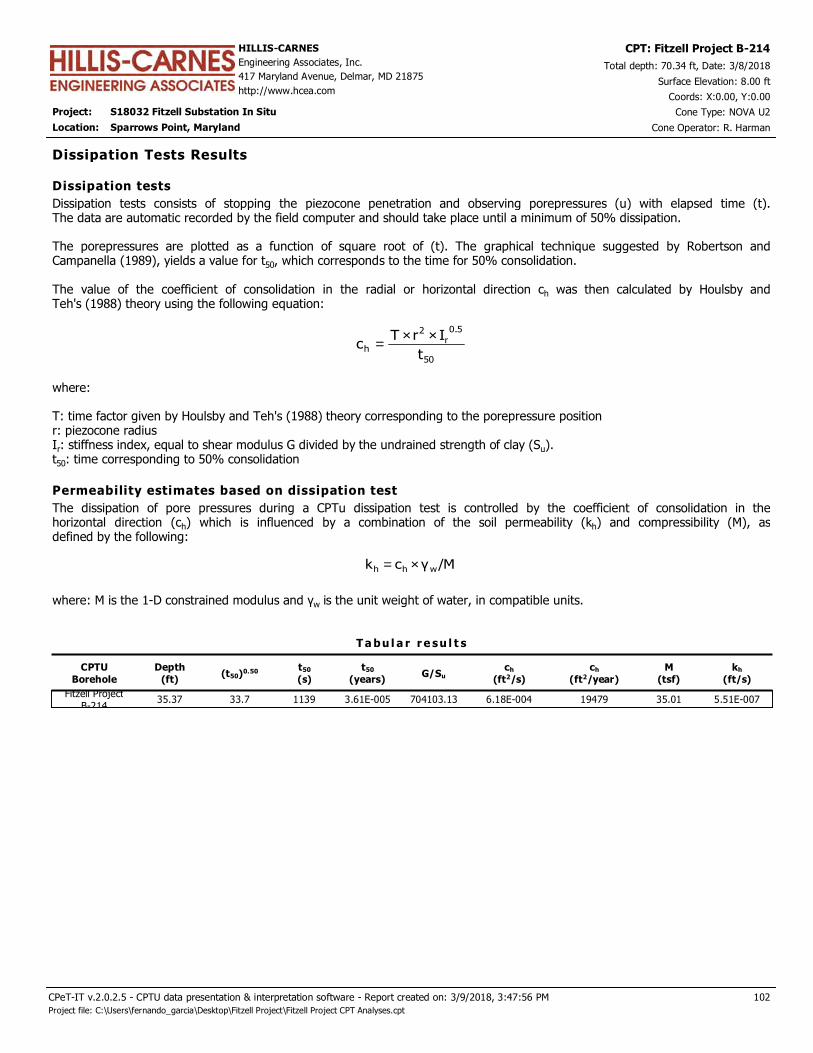
Project: S18032 Fitzell Substation In Situ
HILLIS-CARNES
Engineering Associates, Inc.
417 Maryland Avenue, Delmar, MD 21875
http://www.hcea.com
Total depth: 70.34 ft, Date: 3/8/2018
Surface Elevation: 8.00 ft
Sparrows Point, Maryland
Coords: X:0.00, Y:0.00
Cone Type: NOVA U2
Cone Operator: R. Harman
CPT: Fitzell Project B-214
Location:
CPTU
Borehole
Depth
(ft)(t50)0.50 t50
(s)
t50
(years)G/Su
ch
(ft2/s)
ch
(ft2/year)
T a bu l a r r e su l t s
Dissipation Tests Results
Dissipation tests consists of stopping the piezocone penetration and observing porepressures (u) with elapsed time (t).The data are automatic recorded by the field computer and should take place until a minimum of 50% dissipation. The porepressures are plotted as a function of square root of (t). The graphical technique suggested by Robertson andCampanella (1989), yields a value for t50, which corresponds to the time for 50% consolidation. The value of the coefficient of consolidation in the radial or horizontal direction ch was then calculated by Houlsby andTeh's (1988) theory using the following equation:
50
5.0
r2
ht
IrTc
××=
where: T: time factor given by Houlsby and Teh's (1988) theory corresponding to the porepressure positionr: piezocone radiusIr: stiffness index, equal to shear modulus G divided by the undrained strength of clay (Su).t50: time corresponding to 50% consolidation
Dissipation tests
Permeability estimates based on dissipation test
The dissipation of pore pressures during a CPTu dissipation test is controlled by the coefficient of consolidation in thehorizontal direction (ch) which is influenced by a combination of the soil permeability (kh) and compressibility (M), asdefined by the following:
/Mγck whh ×=
where: M is the 1-D constrained modulus and γw is the unit weight of water, in compatible units.
M
(tsf)
kh
(ft/s)
Fitzell Project
B-21435.37 33.7 1139 3.61E-005 704103.13 6.18E-004 19479 35.01 5.51E-007
102
Project file: C:\Users\fernando_garcia\Desktop\Fitzell Project\Fitzell Project CPT Analyses.cpt
CPeT-IT v.2.0.2.5 - CPTU data presentation & interpretation software - Report created on: 3/9/2018, 3:47:56 PM

This software is licensed to: Fernando Garcia CPT name: Fitzell Project B-214
Piezocone Dissipation Test: Fitzell Project B-214Depth: 35.37 (ft)
t^0.50 (s^0.50)605550454035302520151050
Pore
pre
ssure
u2 (
psi
)
36
34
32
30
28
26
24
22
20
18
16
14
12
10
8
6
433.749
Piezocone Dissipation Test: Fitzell Project B-214Depth: 35.37 (ft)
u0 = 12.30 (psi)
u initial dissipation
assumed initial pore pressure, uiPore pressure
Pressure (psi)2000
Depth
(ft
)
70
65
60
55
50
45
40
35
30
25
20
15
10
5
0
Legend
u2 penetration
Initial dissipation
End of dissipation (extrapolated)
Initial estimated at t=0
Pore pressure
103
Project file: C:\Users\fernando_garcia\Desktop\Fitzell Project\Fitzell Project CPT Analyses.cpt
CPeT-IT v.2.0.2.5 - CPTU data presentation & interpretation software - Report created on: 3/9/2018, 3:47:56 PM
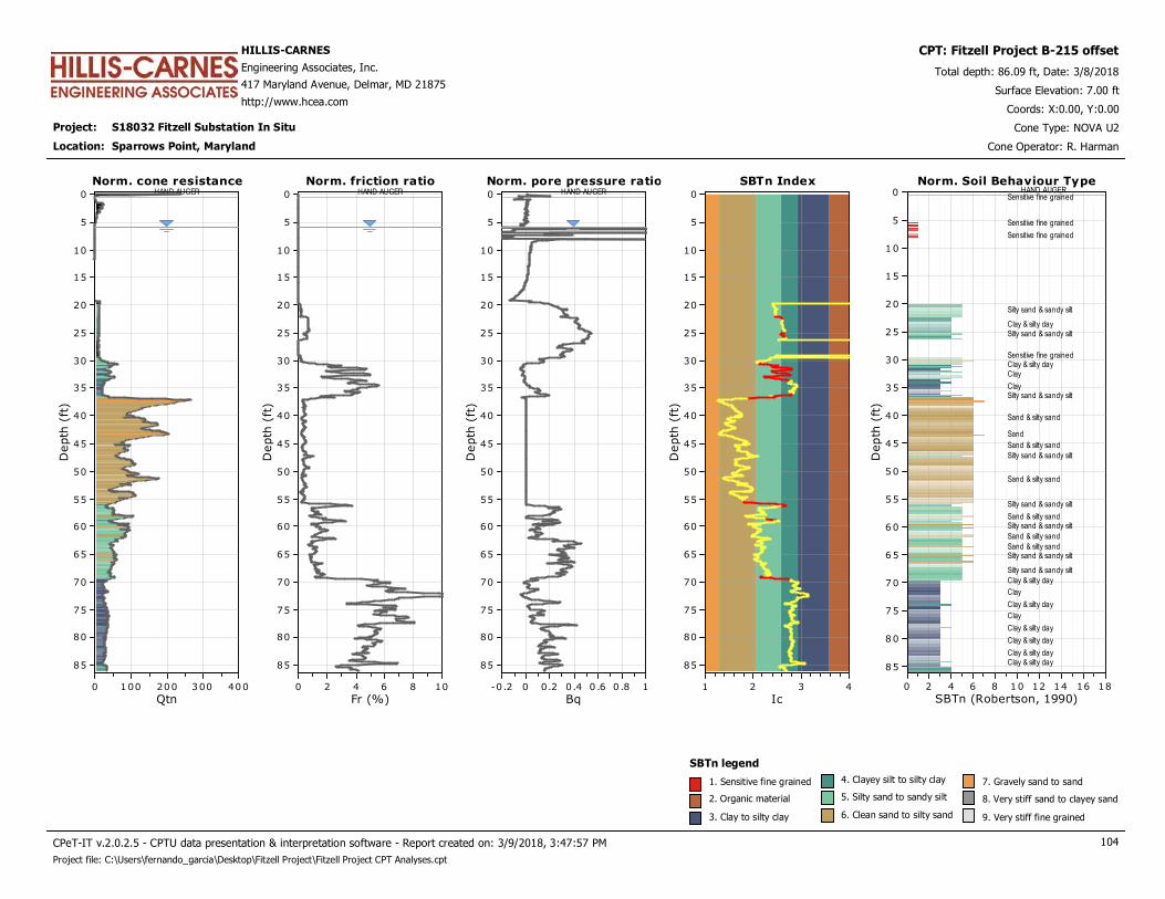
Project: S18032 Fitzell Substation In Situ
HILLIS-CARNES
Engineering Associates, Inc.
417 Maryland Avenue, Delmar, MD 21875
http://www.hcea.com
Total depth: 86.09 ft, Date: 3/8/2018
Surface Elevation: 7.00 ft
Sparrows Point, Maryland
Coords: X:0.00, Y:0.00
Cone Type: NOVA U2
Cone Operator: R. Harman
CPT: Fitzell Project B-215 offset
Location:
Norm. cone resistanceHAND AUGER
Qtn4003002001000
Depth
(ft
)
85
80
75
70
65
60
55
50
45
40
35
30
25
20
15
10
5
0
Norm. cone resistance Norm. pore pressure ratioHAND AUGER
Bq10 .80 .60.40.20-0.2
Depth
(ft
)
85
80
75
70
65
60
55
50
45
40
35
30
25
20
15
10
5
0
Norm. pore pressure ratioNorm. friction ratioHAND AUGER
Fr (%)1086420
Depth
(ft
)
85
80
75
70
65
60
55
50
45
40
35
30
25
20
15
10
5
0
Norm. friction ratio SBTn Index
Ic4321
Depth
(ft
)85
80
75
70
65
60
55
50
45
40
35
30
25
20
15
10
5
0
SBTn Index Norm. Soil Behaviour TypeHAND AUGER
SBTn (Robertson, 1990)181614121086420
Depth
(ft
)
85
80
75
70
65
60
55
50
45
40
35
30
25
20
15
10
5
0Norm. Soil Behaviour Type
Sensitive fine grained
Sensitive fine grained
Sensitive fine grained
Silty sand & sandy silt
Clay & silty claySilty sand & sandy silt
Sensitive fine grainedClay & silty clayClay
ClaySilty sand & sandy silt
Sand & silty sand
Sand
Sand & silty sand
Silty sand & sandy silt
Sand & silty sand
Silty sand & sandy silt
Sand & silty sandSilty sand & sandy silt
Sand & silty sand
Sand & silty sandSilty sand & sandy silt
Silty sand & sandy silt
Clay & silty clay
Clay
Clay & silty clay
Clay
Clay & silty clay
Clay & silty clay
Clay & silty clayClay & silty clay
SBTn legend
1. Sensitive fine grained
2. Organic material
3. Clay to silty clay
4. Clayey silt to silty clay
5. Silty sand to sandy silt
6. Clean sand to silty sand
7. Gravely sand to sand
8. Very stiff sand to clayey sand
9. Very stiff fine grained
CPeT-IT v.2.0.2.5 - CPTU data presentation & interpretation software - Report created on: 3/9/2018, 3:47:57 PM 104
Project file: C:\Users\fernando_garcia\Desktop\Fitzell Project\Fitzell Project CPT Analyses.cpt
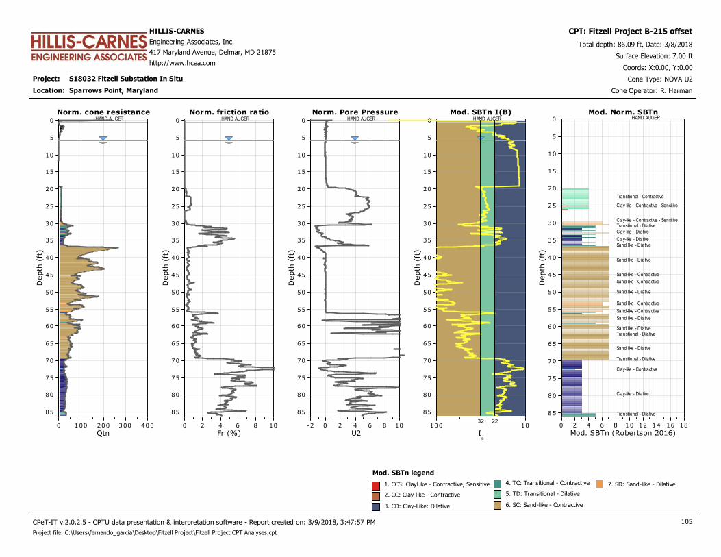
Project: S18032 Fitzell Substation In Situ
HILLIS-CARNES
Engineering Associates, Inc.
417 Maryland Avenue, Delmar, MD 21875
http://www.hcea.com
Total depth: 86.09 ft, Date: 3/8/2018
Surface Elevation: 7.00 ft
Sparrows Point, Maryland
Coords: X:0.00, Y:0.00
Cone Type: NOVA U2
Cone Operator: R. Harman
CPT: Fitzell Project B-215 offset
Location:
Norm. cone resistanceHAND AUGER
Qtn4003002001000
Depth
(ft
)
85
80
75
70
65
60
55
50
45
40
35
30
25
20
15
10
5
0
Norm. cone resistance Norm. Pore PressureHAND AUGER
U21086420-2
Depth
(ft
)
85
80
75
70
65
60
55
50
45
40
35
30
25
20
15
10
5
0
Norm. Pore PressureNorm. friction ratioHAND AUGER
Fr (%)1086420
Depth
(ft
)
85
80
75
70
65
60
55
50
45
40
35
30
25
20
15
10
5
0
Norm. friction ratio Mod. SBTn I(B)HAND AUGER
IB
10100
Depth
(ft
)85
80
75
70
65
60
55
50
45
40
35
30
25
20
15
10
5
0
Mod. SBTn I(B)
2232
Mod. Norm. SBTnHAND AUGER
Mod. SBTn (Robertson 2016)181614121086420
Depth
(ft
)
85
80
75
70
65
60
55
50
45
40
35
30
25
20
15
10
5
0Mod. Norm. SBTn
Transitional - Contractive
Clay-like - Contractive - Sensitive
Clay-like - Contractive - SensitiveTransitional - DilativeClay-like - Dilative
Clay-like - DilativeSand like - Dilative
Sand like - Dilative
Sand-like - Contractive
Sand-like - Contractive
Sand like - Dilative
Sand-like - Contractive
Sand-like - Contractive
Sand like - Dilative
Sand like - DilativeTransitional - Dilative
Sand like - Dilative
Transitional - Dilative
Clay-like - Contractive
Clay-like - Dilative
Transitional - Dilative
Mod. SBTn legend
1. CCS: ClayLike - Contractive, Sensitive
2. CC: Clay-like - Contractive
3. CD: Clay-Like: Dilative
4. TC: Transitional - Contractive
5. TD: Transitional - Dilative
6. SC: Sand-like - Contractive
7. SD: Sand-like - Dilative
CPeT-IT v.2.0.2.5 - CPTU data presentation & interpretation software - Report created on: 3/9/2018, 3:47:57 PM 105
Project file: C:\Users\fernando_garcia\Desktop\Fitzell Project\Fitzell Project CPT Analyses.cpt
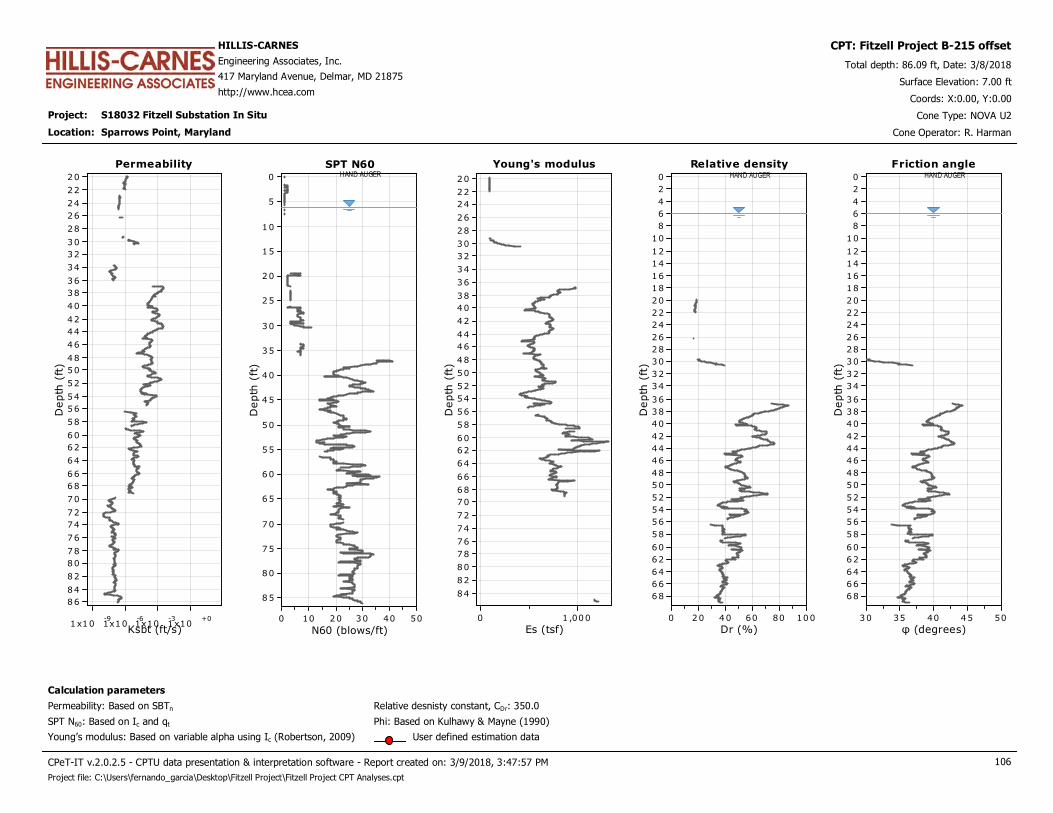
Project: S18032 Fitzell Substation In Situ
HILLIS-CARNES
Engineering Associates, Inc.
417 Maryland Avenue, Delmar, MD 21875
http://www.hcea.com
Total depth: 86.09 ft, Date: 3/8/2018
Surface Elevation: 7.00 ft
Sparrows Point, Maryland
Coords: X:0.00, Y:0.00
Cone Type: NOVA U2
Cone Operator: R. Harman
CPT: Fitzell Project B-215 offset
Location:
Permeability
Ksbt (ft/s)1x10
-91x10
-61x10
-31x10
+0
Depth
(ft
)
86
84
82
80
78
76
74
72
70
68
66
64
62
60
58
56
54
52
50
48
46
44
42
40
38
36
34
32
30
28
26
24
22
20
Permeability Young's modulus
Es (tsf)1 ,0000
Depth
(ft
)
84
82
80
78
76
74
72
70
68
66
64
62
60
58
56
54
52
50
48
46
44
42
40
38
36
34
32
30
28
26
24
22
20
Young's modulusSPT N60HAND AUGER
N60 (blows/ft)50403020100
Depth
(ft
)
85
80
75
70
65
60
55
50
45
40
35
30
25
20
15
10
5
0
SPT N60 Relative densityHAND AUGER
Dr (%)100806040200
Depth
(ft
)
68
66
64
62
60
58
56
54
52
50
48
46
44
42
40
38
36
34
32
30
28
26
24
22
20
18
16
14
12
10
8
6
4
2
0
Relative density
Calculation parameters
Relative desnisty constant, CDr: 350.0Permeability: Based on SBTn
SPT N60: Based on Ic and qt
Young’s modulus: Based on variable alpha using Ic (Robertson, 2009)
Phi: Based on Kulhawy & Mayne (1990)
User defined estimation data
Friction angleHAND AUGER
φ (degrees)5045403530
Depth
(ft
)
68
66
64
62
60
58
56
54
52
50
48
46
44
42
40
38
36
34
32
30
28
26
24
22
20
18
16
14
12
10
8
6
4
2
0
Friction angle
CPeT-IT v.2.0.2.5 - CPTU data presentation & interpretation software - Report created on: 3/9/2018, 3:47:57 PM 106
Project file: C:\Users\fernando_garcia\Desktop\Fitzell Project\Fitzell Project CPT Analyses.cpt
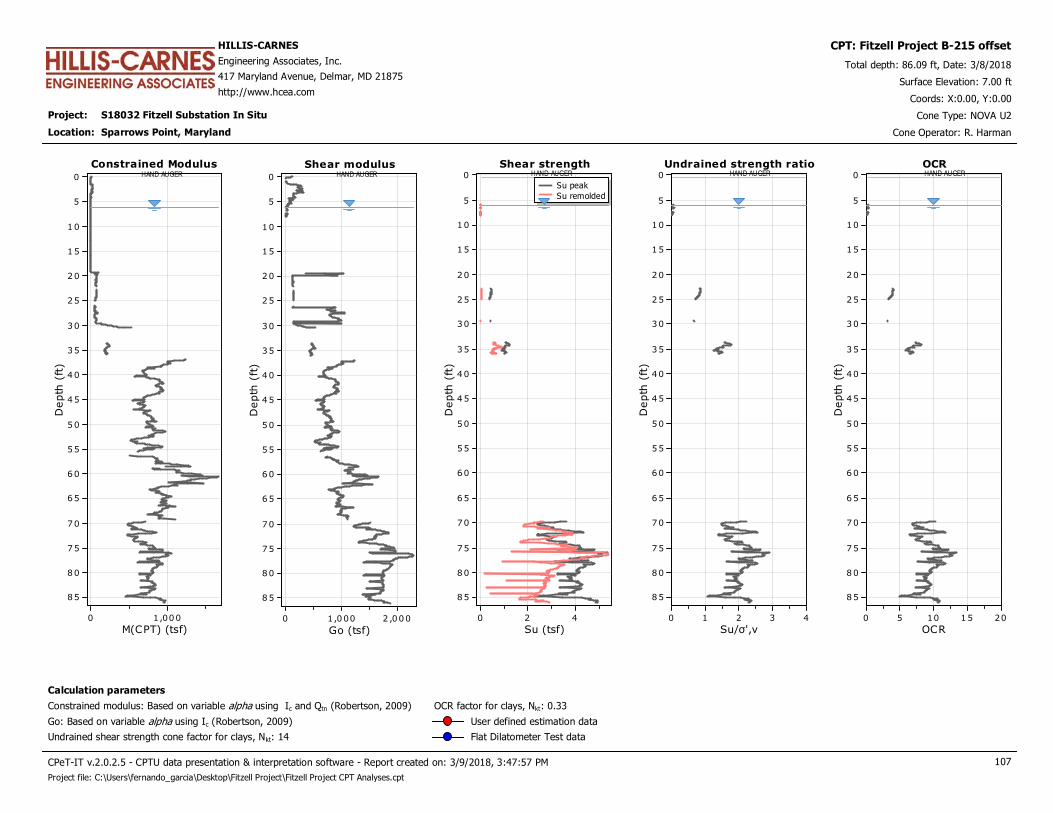
Project: S18032 Fitzell Substation In Situ
HILLIS-CARNES
Engineering Associates, Inc.
417 Maryland Avenue, Delmar, MD 21875
http://www.hcea.com
Total depth: 86.09 ft, Date: 3/8/2018
Surface Elevation: 7.00 ft
Sparrows Point, Maryland
Coords: X:0.00, Y:0.00
Cone Type: NOVA U2
Cone Operator: R. Harman
CPT: Fitzell Project B-215 offset
Location:
Constrained ModulusHAND AUGER
M(CPT) (tsf)1,0000
Depth
(ft
)
85
80
75
70
65
60
55
50
45
40
35
30
25
20
15
10
5
0
Constrained Modulus Shear strengthHAND AUGER
Su (tsf)420
Depth
(ft
)
85
80
75
70
65
60
55
50
45
40
35
30
25
20
15
10
5
0Su peak
Su remolded
Shear strengthShear modulusHAND AUGER
Go (tsf)2 ,0001,0000
Depth
(ft
)
85
80
75
70
65
60
55
50
45
40
35
30
25
20
15
10
5
0
Shear modulus Undrained strength ratioHAND AUGER
Su/σ',v43210
Depth
(ft
)
85
80
75
70
65
60
55
50
45
40
35
30
25
20
15
10
5
0
Undrained strength ratio OCRHAND AUGER
OCR20151050
Depth
(ft
)
85
80
75
70
65
60
55
50
45
40
35
30
25
20
15
10
5
0
OCR
Calculation parameters
Undrained shear strength cone factor for clays, Nkt: 14
OCR factor for clays, Nkt: 0.33
Go: Based on variable alpha using Ic (Robertson, 2009)
Constrained modulus: Based on variable alpha using Ic and Qtn (Robertson, 2009)
User defined estimation data
Flat Dilatometer Test data
CPeT-IT v.2.0.2.5 - CPTU data presentation & interpretation software - Report created on: 3/9/2018, 3:47:57 PM 107
Project file: C:\Users\fernando_garcia\Desktop\Fitzell Project\Fitzell Project CPT Analyses.cpt
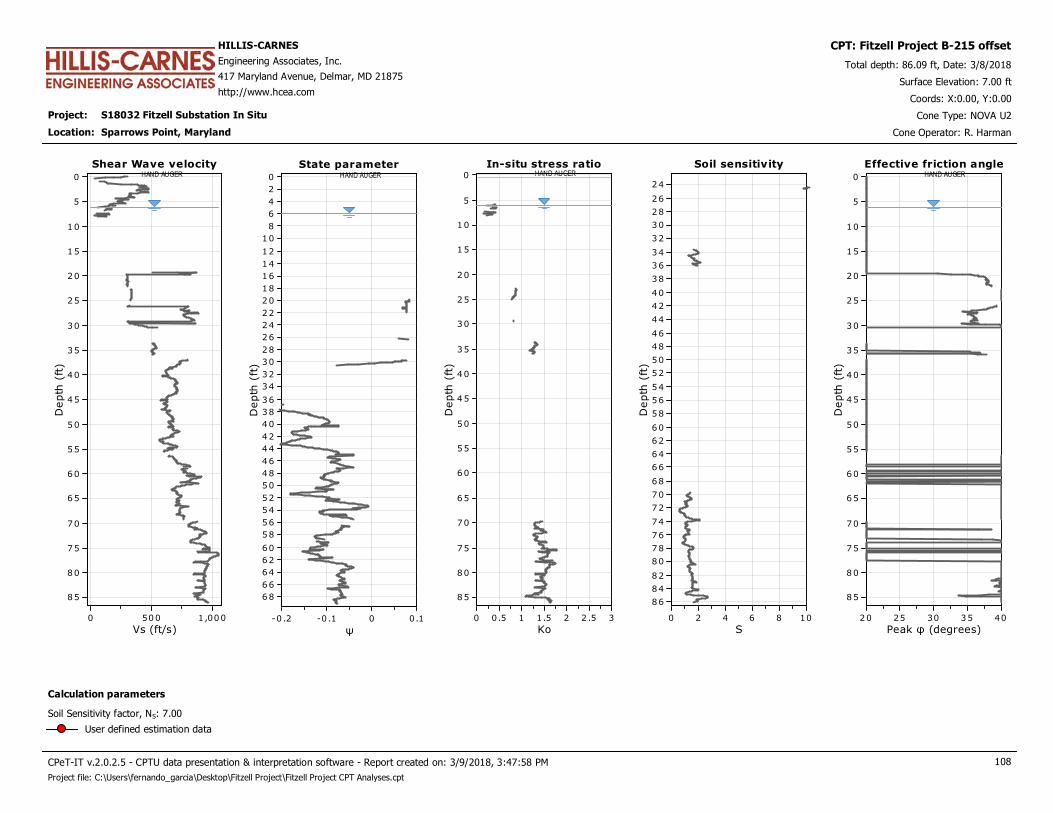
Project: S18032 Fitzell Substation In Situ
HILLIS-CARNES
Engineering Associates, Inc.
417 Maryland Avenue, Delmar, MD 21875
http://www.hcea.com
Total depth: 86.09 ft, Date: 3/8/2018
Surface Elevation: 7.00 ft
Sparrows Point, Maryland
Coords: X:0.00, Y:0.00
Cone Type: NOVA U2
Cone Operator: R. Harman
CPT: Fitzell Project B-215 offset
Location:
Shear Wave velocityHAND AUGER
Vs (ft/s)1,0005000
Depth
(ft
)
85
80
75
70
65
60
55
50
45
40
35
30
25
20
15
10
5
0
Shear Wave velocity In-situ stress ratioHAND AUGER
Ko32 .521.510.50
Depth
(ft
)
85
80
75
70
65
60
55
50
45
40
35
30
25
20
15
10
5
0
In-situ stress ratioState parameterHAND AUGER
ψ0.10-0 .1-0 .2
Depth
(ft
)
68
66
64
62
60
58
56
54
52
50
48
46
44
42
40
38
36
34
32
30
28
26
24
22
20
18
16
14
12
10
8
6
4
2
0
State parameter Soil sensitivity
S1086420
Depth
(ft
)
86
84
82
80
78
76
74
72
70
68
66
64
62
60
58
56
54
52
50
48
46
44
42
40
38
36
34
32
30
28
26
24
Soil sensitivity Effective friction angleHAND AUGER
Peak φ (degrees)4035302520
Depth
(ft
)
85
80
75
70
65
60
55
50
45
40
35
30
25
20
15
10
5
0
Effective friction angle
Calculation parameters
Soil Sensitivity factor, NS: 7.00
User defined estimation data
CPeT-IT v.2.0.2.5 - CPTU data presentation & interpretation software - Report created on: 3/9/2018, 3:47:58 PM 108
Project file: C:\Users\fernando_garcia\Desktop\Fitzell Project\Fitzell Project CPT Analyses.cpt

Project: S18032 Fitzell Substation In Situ
HILLIS-CARNES
Engineering Associates, Inc.
417 Maryland Avenue, Delmar, MD 21875
http://www.hcea.com
Total depth: 86.09 ft, Date: 3/8/2018
Surface Elevation: 7.00 ft
Sparrows Point, Maryland
Coords: X:0.00, Y:0.00
Cone Type: NOVA U2
Cone Operator: R. Harman
CPT: Fitzell Project B-215 offset
Location:
CPTU
Borehole
Depth
(ft)(t50)0.50 t50
(s)
t50
(years)G/Su
ch
(ft2/s)
ch
(ft2/year)
T a bu l a r r e su l t s
Dissipation Tests Results
Dissipation tests consists of stopping the piezocone penetration and observing porepressures (u) with elapsed time (t).The data are automatic recorded by the field computer and should take place until a minimum of 50% dissipation. The porepressures are plotted as a function of square root of (t). The graphical technique suggested by Robertson andCampanella (1989), yields a value for t50, which corresponds to the time for 50% consolidation. The value of the coefficient of consolidation in the radial or horizontal direction ch was then calculated by Houlsby andTeh's (1988) theory using the following equation:
50
5.0
r2
ht
IrTc
××=
where: T: time factor given by Houlsby and Teh's (1988) theory corresponding to the porepressure positionr: piezocone radiusIr: stiffness index, equal to shear modulus G divided by the undrained strength of clay (Su).t50: time corresponding to 50% consolidation
Dissipation tests
Permeability estimates based on dissipation test
The dissipation of pore pressures during a CPTu dissipation test is controlled by the coefficient of consolidation in thehorizontal direction (ch) which is influenced by a combination of the soil permeability (kh) and compressibility (M), asdefined by the following:
/Mγck whh ×=
where: M is the 1-D constrained modulus and γw is the unit weight of water, in compatible units.
M
(tsf)
kh
(ft/s)
Fitzell Project
B-21538.42 0.0 0 0.00E+000 100.00 0.00E+000 0 787.06 -1.00E+004
Fitzell Project
B-21575.82 35.3 1244 3.95E-005 429223.78 4.41E-004 13923 812.43 1.70E-008
109
Project file: C:\Users\fernando_garcia\Desktop\Fitzell Project\Fitzell Project CPT Analyses.cpt
CPeT-IT v.2.0.2.5 - CPTU data presentation & interpretation software - Report created on: 3/9/2018, 3:47:58 PM

This software is licensed to: Fernando Garcia CPT name: Fitzell Project B-215 offset
Piezocone Dissipation Test: Fitzell Project B-215 offsetDepth: 38.42 (ft)
t^0.50 (s^0.50)181614121086420
Pore
pre
ssure
u2 (
psi
)14.1
14
13.9
13.8
13.7
13.6
13.5
13.4
13.3
13.2
13.1
13
12.9
12.8
12.7
12.6
12.5
12.4
12.3
12.2
12.1
12
11.9
11.8
11.7
Piezocone Dissipation Test: Fitzell Project B-215 offsetDepth: 38.42 (ft)
u0 = 14.06 (psi)
Pore pressure
Pressure (psi)2000
Depth
(ft
)
85
80
75
70
65
60
55
50
45
40
35
30
25
20
15
10
5
0
Legend
u2 penetration
Initial dissipation
End of dissipation (extrapolated)
Initial estimated at t=0
Pore pressure
110
Project file: C:\Users\fernando_garcia\Desktop\Fitzell Project\Fitzell Project CPT Analyses.cpt
CPeT-IT v.2.0.2.5 - CPTU data presentation & interpretation software - Report created on: 3/9/2018, 3:47:58 PM
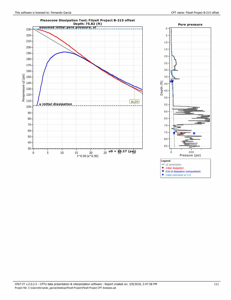
This software is licensed to: Fernando Garcia CPT name: Fitzell Project B-215 offset
Piezocone Dissipation Test: Fitzell Project B-215 offsetDepth: 75.82 (ft)
t^0.50 (s^0.50)35302520151050
Pore
pre
ssure
u2 (
psi
)
230
220
210
200
190
180
170
160
150
140
130
120
110
100
90
80
70
60
50
40
30
35.273
Piezocone Dissipation Test: Fitzell Project B-215 offsetDepth: 75.82 (ft)
u0 = 30.27 (psi)
u initial dissipation
assumed initial pore pressure, uiPore pressure
Pressure (psi)2000
Depth
(ft
)
85
80
75
70
65
60
55
50
45
40
35
30
25
20
15
10
5
0
Legend
u2 penetration
Initial dissipation
End of dissipation (extrapolated)
Initial estimated at t=0
Pore pressure
111
Project file: C:\Users\fernando_garcia\Desktop\Fitzell Project\Fitzell Project CPT Analyses.cpt
CPeT-IT v.2.0.2.5 - CPTU data presentation & interpretation software - Report created on: 3/9/2018, 3:47:58 PM
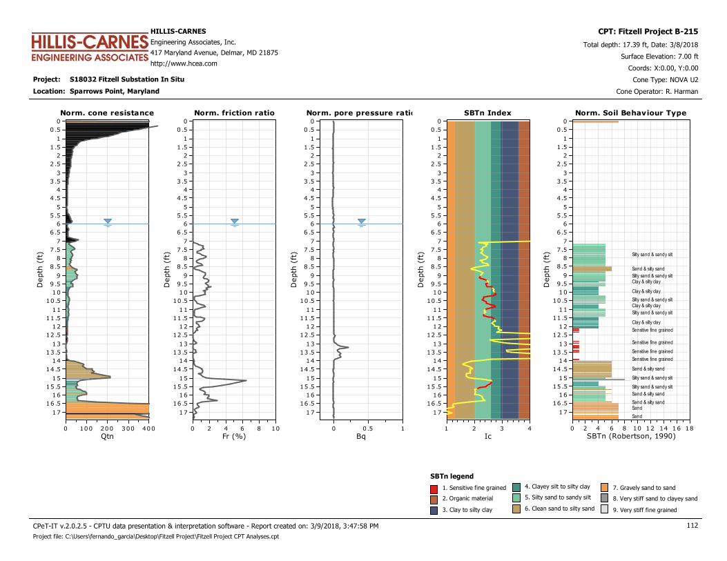
Project: S18032 Fitzell Substation In Situ
HILLIS-CARNES
Engineering Associates, Inc.
417 Maryland Avenue, Delmar, MD 21875
http://www.hcea.com
Total depth: 17.39 ft, Date: 3/8/2018
Surface Elevation: 7.00 ft
Sparrows Point, Maryland
Coords: X:0.00, Y:0.00
Cone Type: NOVA U2
Cone Operator: R. Harman
CPT: Fitzell Project B-215
Location:
Norm. cone resistance
Qtn4003002001000
Depth
(ft
)
17
16 .5
16
15 .5
15
14 .5
14
13 .5
13
12 .5
12
11 .5
11
10 .5
10
9 .5
9
8 .5
8
7 .5
7
6 .5
6
5 .5
5
4 .5
4
3 .5
3
2 .5
2
1 .5
1
0 .5
0
Norm. cone resistance Norm. pore pressure ratio
Bq10.50
Depth
(ft
)
17
16 .5
16
15 .5
15
14 .5
14
13 .5
13
12 .5
12
11 .5
11
10 .5
10
9 .5
9
8 .5
8
7 .5
7
6 .5
6
5 .5
5
4 .5
4
3 .5
3
2 .5
2
1 .5
1
0 .5
0
Norm. pore pressure ratioNorm. friction ratio
Fr (%)1086420
Depth
(ft
)
17
16 .5
16
15 .5
15
14 .5
14
13 .5
13
12 .5
12
11 .5
11
10 .5
10
9 .5
9
8 .5
8
7 .5
7
6 .5
6
5 .5
5
4 .5
4
3 .5
3
2 .5
2
1 .5
1
0 .5
0
Norm. friction ratio SBTn Index
Ic4321
Depth
(ft
)17
16 .5
16
15 .5
15
14 .5
14
13 .5
13
12 .5
12
11 .5
11
10 .5
10
9 .5
9
8 .5
8
7 .5
7
6 .5
6
5 .5
5
4 .5
4
3 .5
3
2 .5
2
1 .5
1
0 .5
0
SBTn Index Norm. Soil Behaviour Type
SBTn (Robertson, 1990)181614121086420
Depth
(ft
)
17
16 .5
16
15 .5
15
14 .5
14
13 .5
13
12 .5
12
11 .5
11
10 .5
10
9.5
9
8.5
8
7.5
7
6.5
6
5.5
5
4.5
4
3.5
3
2.5
2
1.5
1
0.5
0
Norm. Soil Behaviour Type
Silty sand & sandy silt
Sand & silty sand
Silty sand & sandy siltClay & silty clay
Clay & silty clay
Silty sand & sandy siltClay & silty clay
Silty sand & sandy silt
Clay & silty clay
Sensitive fine grained
Sensitive fine grained
Sensitive fine grained
Sensitive fine grained
Sand & silty sand
Silty sand & sandy silt
Silty sand & sandy silt
Sand & silty sand
Sand & silty sandSand
Sand
SBTn legend
1. Sensitive fine grained
2. Organic material
3. Clay to silty clay
4. Clayey silt to silty clay
5. Silty sand to sandy silt
6. Clean sand to silty sand
7. Gravely sand to sand
8. Very stiff sand to clayey sand
9. Very stiff fine grained
CPeT-IT v.2.0.2.5 - CPTU data presentation & interpretation software - Report created on: 3/9/2018, 3:47:58 PM 112
Project file: C:\Users\fernando_garcia\Desktop\Fitzell Project\Fitzell Project CPT Analyses.cpt

Project: S18032 Fitzell Substation In Situ
HILLIS-CARNES
Engineering Associates, Inc.
417 Maryland Avenue, Delmar, MD 21875
http://www.hcea.com
Total depth: 17.39 ft, Date: 3/8/2018
Surface Elevation: 7.00 ft
Sparrows Point, Maryland
Coords: X:0.00, Y:0.00
Cone Type: NOVA U2
Cone Operator: R. Harman
CPT: Fitzell Project B-215
Location:
Norm. cone resistance
Qtn4003002001000
Depth
(ft
)
17
16 .5
16
15 .5
15
14 .5
14
13 .5
13
12 .5
12
11 .5
11
10 .5
10
9 .5
9
8 .5
8
7 .5
7
6 .5
6
5 .5
5
4 .5
4
3 .5
3
2 .5
2
1 .5
1
0 .5
0
Norm. cone resistance Norm. Pore Pressure
U21086420-2
Depth
(ft
)
17
16 .5
16
15 .5
15
14 .5
14
13 .5
13
12 .5
12
11 .5
11
10 .5
10
9 .5
9
8 .5
8
7 .5
7
6 .5
6
5 .5
5
4 .5
4
3 .5
3
2 .5
2
1 .5
1
0 .5
0
Norm. Pore PressureNorm. friction ratio
Fr (%)1086420
Depth
(ft
)
17
16 .5
16
15 .5
15
14 .5
14
13 .5
13
12 .5
12
11 .5
11
10 .5
10
9 .5
9
8 .5
8
7 .5
7
6 .5
6
5 .5
5
4 .5
4
3 .5
3
2 .5
2
1 .5
1
0 .5
0
Norm. friction ratio Mod. SBTn I(B)
IB
10100
Depth
(ft
)17
16 .5
16
15 .5
15
14 .5
14
13 .5
13
12 .5
12
11 .5
11
10 .5
10
9 .5
9
8 .5
8
7 .5
7
6 .5
6
5 .5
5
4 .5
4
3 .5
3
2 .5
2
1 .5
1
0 .5
0
Mod. SBTn I(B)
2232
Mod. Norm. SBTn
Mod. SBTn (Robertson 2016)181614121086420
Depth
(ft
)
17
16 .5
16
15 .5
15
14 .5
14
13 .5
13
12 .5
12
11 .5
11
10 .5
10
9.5
9
8.5
8
7.5
7
6.5
6
5.5
5
4.5
4
3.5
3
2.5
2
1.5
1
0.5
0
Mod. Norm. SBTn
Sand-like - Contractive
Sand-like - Contractive
Sand-like - Contractive
Sand like - Dilative
Transitional - Dilative
Transitional - Contractive
Sand-like - ContractiveTransitional - Contractive
Transitional - ContractiveTransitional - Contractive
Clay-like - Contractive - Sensitive
Clay-like - Contractive - Sensitive
Clay-like - Contractive - Sensitive
Clay-like - Contractive - Sensitive
Sand like - Dilative
Transitional - Dilative
Transitional - Dilative
Sand like - Dilative
Transitional - Dilative
Sand like - Dilative
Sand like - Dilative
Mod. SBTn legend
1. CCS: ClayLike - Contractive, Sensitive
2. CC: Clay-like - Contractive
3. CD: Clay-Like: Dilative
4. TC: Transitional - Contractive
5. TD: Transitional - Dilative
6. SC: Sand-like - Contractive
7. SD: Sand-like - Dilative
CPeT-IT v.2.0.2.5 - CPTU data presentation & interpretation software - Report created on: 3/9/2018, 3:47:59 PM 113
Project file: C:\Users\fernando_garcia\Desktop\Fitzell Project\Fitzell Project CPT Analyses.cpt

Project: S18032 Fitzell Substation In Situ
HILLIS-CARNES
Engineering Associates, Inc.
417 Maryland Avenue, Delmar, MD 21875
http://www.hcea.com
Total depth: 17.39 ft, Date: 3/8/2018
Surface Elevation: 7.00 ft
Sparrows Point, Maryland
Coords: X:0.00, Y:0.00
Cone Type: NOVA U2
Cone Operator: R. Harman
CPT: Fitzell Project B-215
Location:
Permeability
Ksbt (ft/s)1x10
-91x10
-61x10
-31x10
+0
Depth
(ft
)
17
16
15
14
13
12
11
10
9
8
Permeability Young's modulus
Es (tsf)2,0001,0000
Depth
(ft
)
17
16
15
14
13
12
11
10
9
8
7Young's modulusSPT N60
N60 (blows/ft)50403020100
Depth
(ft
)
17
16
15
14
13
12
11
10
9
8
7
6
5
4
3
2
1
0
SPT N60 Relative density
Dr (%)100806040200
Depth
(ft
)
17
16
15
14
13
12
11
10
9
8
7
6
5
4
3
2
1
0
Relative density
Calculation parameters
Relative desnisty constant, CDr: 350.0Permeability: Based on SBTn
SPT N60: Based on Ic and qt
Young’s modulus: Based on variable alpha using Ic (Robertson, 2009)
Phi: Based on Kulhawy & Mayne (1990)
User defined estimation data
Friction angle
φ (degrees)5045403530
Depth
(ft
)
17
16
15
14
13
12
11
10
9
8
7
6
5
4
3
2
1
0
Friction angle
CPeT-IT v.2.0.2.5 - CPTU data presentation & interpretation software - Report created on: 3/9/2018, 3:47:59 PM 114
Project file: C:\Users\fernando_garcia\Desktop\Fitzell Project\Fitzell Project CPT Analyses.cpt
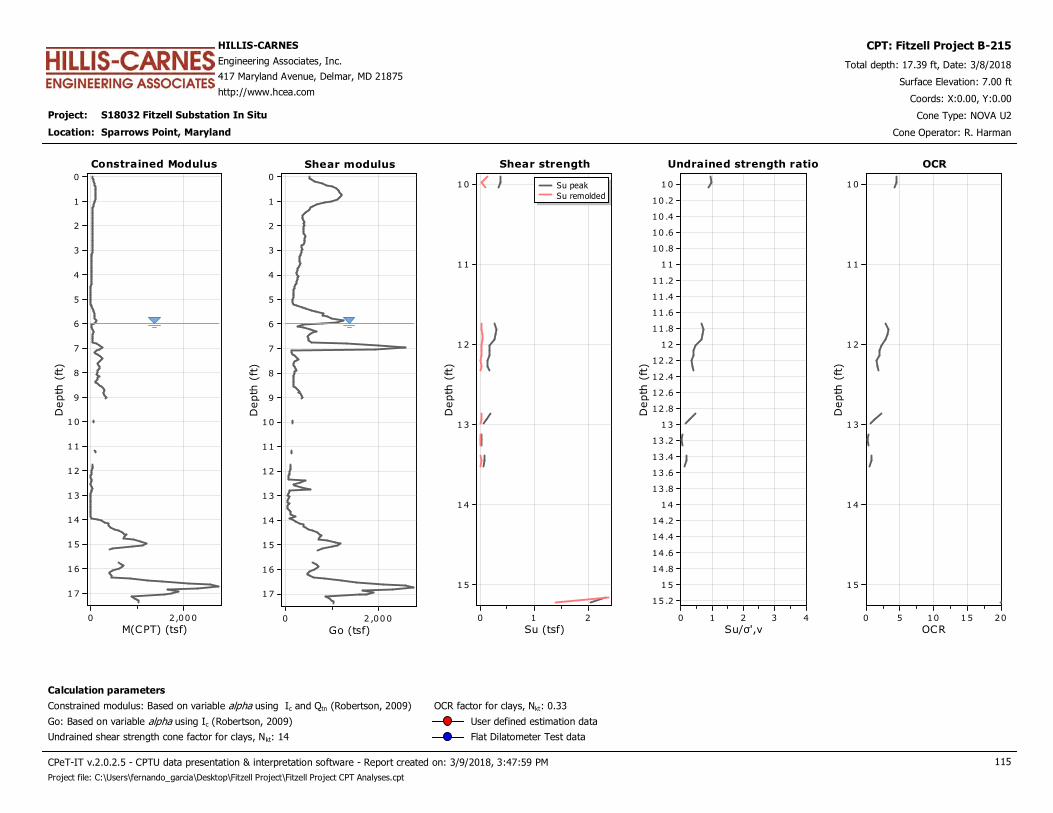
Project: S18032 Fitzell Substation In Situ
HILLIS-CARNES
Engineering Associates, Inc.
417 Maryland Avenue, Delmar, MD 21875
http://www.hcea.com
Total depth: 17.39 ft, Date: 3/8/2018
Surface Elevation: 7.00 ft
Sparrows Point, Maryland
Coords: X:0.00, Y:0.00
Cone Type: NOVA U2
Cone Operator: R. Harman
CPT: Fitzell Project B-215
Location:
Constrained Modulus
M(CPT) (tsf)2,0000
Depth
(ft
)
17
16
15
14
13
12
11
10
9
8
7
6
5
4
3
2
1
0
Constrained Modulus Shear strength
Su (tsf)210
Depth
(ft
)
15
14
13
12
11
10 Su peak
Su remolded
Shear strengthShear modulus
Go (tsf)2 ,0000
Depth
(ft
)
17
16
15
14
13
12
11
10
9
8
7
6
5
4
3
2
1
0
Shear modulus Undrained strength ratio
Su/σ',v43210
Depth
(ft
)
15 .2
15
14 .8
14 .6
14 .4
14 .2
14
13 .8
13 .6
13 .4
13 .2
13
12 .8
12 .6
12 .4
12 .2
12
11 .8
11 .6
11 .4
11 .2
11
10 .8
10 .6
10 .4
10 .2
10
Undrained strength ratio OCR
OCR20151050
Depth
(ft
)
15
14
13
12
11
10
OCR
Calculation parameters
Undrained shear strength cone factor for clays, Nkt: 14
OCR factor for clays, Nkt: 0.33
Go: Based on variable alpha using Ic (Robertson, 2009)
Constrained modulus: Based on variable alpha using Ic and Qtn (Robertson, 2009)
User defined estimation data
Flat Dilatometer Test data
CPeT-IT v.2.0.2.5 - CPTU data presentation & interpretation software - Report created on: 3/9/2018, 3:47:59 PM 115
Project file: C:\Users\fernando_garcia\Desktop\Fitzell Project\Fitzell Project CPT Analyses.cpt
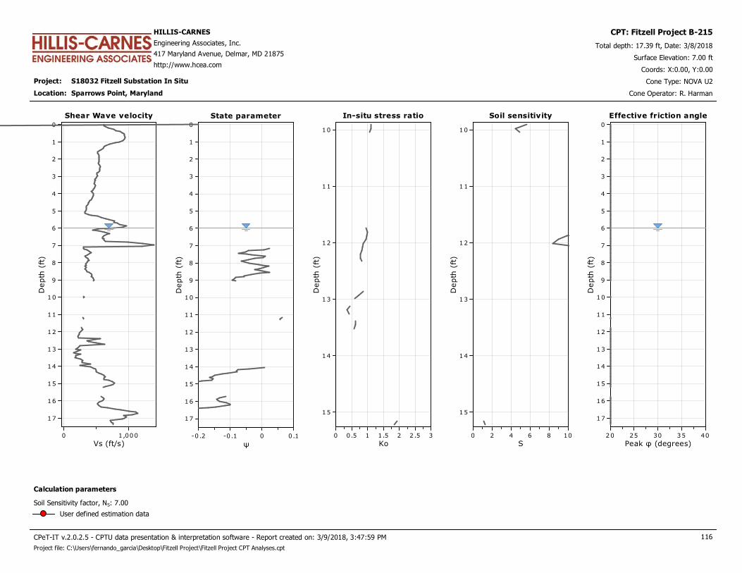
Project: S18032 Fitzell Substation In Situ
HILLIS-CARNES
Engineering Associates, Inc.
417 Maryland Avenue, Delmar, MD 21875
http://www.hcea.com
Total depth: 17.39 ft, Date: 3/8/2018
Surface Elevation: 7.00 ft
Sparrows Point, Maryland
Coords: X:0.00, Y:0.00
Cone Type: NOVA U2
Cone Operator: R. Harman
CPT: Fitzell Project B-215
Location:
Shear Wave velocity
Vs (ft/s)1,0000
Depth
(ft
)
17
16
15
14
13
12
11
10
9
8
7
6
5
4
3
2
1
0
Shear Wave velocity In-situ stress ratio
Ko32 .521.510.50
Depth
(ft
)
15
14
13
12
11
10
In-situ stress ratioState parameter
ψ0.10-0 .1-0 .2
Depth
(ft
)
17
16
15
14
13
12
11
10
9
8
7
6
5
4
3
2
1
0
State parameter Soil sensitivity
S1086420
Depth
(ft
)
15
14
13
12
11
10
Soil sensitivity Effective friction angle
Peak φ (degrees)4035302520
Depth
(ft
)
17
16
15
14
13
12
11
10
9
8
7
6
5
4
3
2
1
0
Effective friction angle
Calculation parameters
Soil Sensitivity factor, NS: 7.00
User defined estimation data
CPeT-IT v.2.0.2.5 - CPTU data presentation & interpretation software - Report created on: 3/9/2018, 3:47:59 PM 116
Project file: C:\Users\fernando_garcia\Desktop\Fitzell Project\Fitzell Project CPT Analyses.cpt
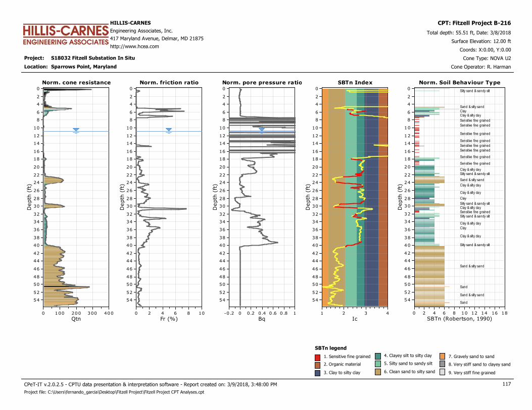
Project: S18032 Fitzell Substation In Situ
HILLIS-CARNES
Engineering Associates, Inc.
417 Maryland Avenue, Delmar, MD 21875
http://www.hcea.com
Total depth: 55.51 ft, Date: 3/8/2018
Surface Elevation: 12.00 ft
Sparrows Point, Maryland
Coords: X:0.00, Y:0.00
Cone Type: NOVA U2
Cone Operator: R. Harman
CPT: Fitzell Project B-216
Location:
Norm. cone resistance
Qtn4003002001000
Depth
(ft
)
54
52
50
48
46
44
42
40
38
36
34
32
30
28
26
24
22
20
18
16
14
12
10
8
6
4
2
0
Norm. cone resistance Norm. pore pressure ratio
Bq10 .80 .60.40.20-0.2
Depth
(ft
)
54
52
50
48
46
44
42
40
38
36
34
32
30
28
26
24
22
20
18
16
14
12
10
8
6
4
2
0
Norm. pore pressure ratioNorm. friction ratio
Fr (%)1086420
Depth
(ft
)
54
52
50
48
46
44
42
40
38
36
34
32
30
28
26
24
22
20
18
16
14
12
10
8
6
4
2
0
Norm. friction ratio SBTn Index
Ic4321
Depth
(ft
)
54
52
50
48
46
44
42
40
38
36
34
32
30
28
26
24
22
20
18
16
14
12
10
8
6
4
2
0
SBTn Index Norm. Soil Behaviour Type
SBTn (Robertson, 1990)181614121086420
Depth
(ft
)
54
52
50
48
46
44
42
40
38
36
34
32
30
28
26
24
22
20
18
16
14
12
10
8
6
4
2
0
Norm. Soil Behaviour Type
Silty sand & sandy silt
Sand & silty sandClayClay & silty clay
Sensitive fine grained
Sensitive fine grained
Sensitive fine grained
Sensitive fine grained
Sensitive fine grained
Sensitive fine grained
Sensitive fine grained
Sensitive fine grained
Clay & silty claySilty sand & sandy silt
Sand & silty sand
Clay & silty clay
Clay & silty clay
Clay
Silty sand & sandy siltClay & silty claySensitive fine grainedSilty sand & sandy silt
Clay & silty clay
Clay
Clay & silty clay
Silty sand & sandy silt
Sand & silty sand
Sand
Sand & silty sand
Sand
SBTn legend
1. Sensitive fine grained
2. Organic material
3. Clay to silty clay
4. Clayey silt to silty clay
5. Silty sand to sandy silt
6. Clean sand to silty sand
7. Gravely sand to sand
8. Very stiff sand to clayey sand
9. Very stiff fine grained
CPeT-IT v.2.0.2.5 - CPTU data presentation & interpretation software - Report created on: 3/9/2018, 3:48:00 PM 117
Project file: C:\Users\fernando_garcia\Desktop\Fitzell Project\Fitzell Project CPT Analyses.cpt
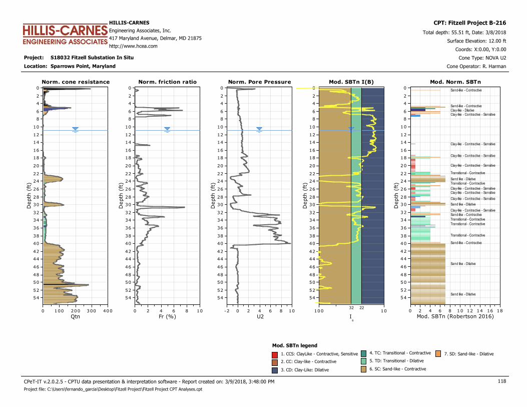
Project: S18032 Fitzell Substation In Situ
HILLIS-CARNES
Engineering Associates, Inc.
417 Maryland Avenue, Delmar, MD 21875
http://www.hcea.com
Total depth: 55.51 ft, Date: 3/8/2018
Surface Elevation: 12.00 ft
Sparrows Point, Maryland
Coords: X:0.00, Y:0.00
Cone Type: NOVA U2
Cone Operator: R. Harman
CPT: Fitzell Project B-216
Location:
Norm. cone resistance
Qtn4003002001000
Depth
(ft
)
54
52
50
48
46
44
42
40
38
36
34
32
30
28
26
24
22
20
18
16
14
12
10
8
6
4
2
0
Norm. cone resistance Norm. Pore Pressure
U21086420-2
Depth
(ft
)
54
52
50
48
46
44
42
40
38
36
34
32
30
28
26
24
22
20
18
16
14
12
10
8
6
4
2
0
Norm. Pore PressureNorm. friction ratio
Fr (%)1086420
Depth
(ft
)
54
52
50
48
46
44
42
40
38
36
34
32
30
28
26
24
22
20
18
16
14
12
10
8
6
4
2
0
Norm. friction ratio Mod. SBTn I(B)
IB
10100
Depth
(ft
)
54
52
50
48
46
44
42
40
38
36
34
32
30
28
26
24
22
20
18
16
14
12
10
8
6
4
2
0
Mod. SBTn I(B)
2232
Mod. Norm. SBTn
Mod. SBTn (Robertson 2016)181614121086420
Depth
(ft
)
54
52
50
48
46
44
42
40
38
36
34
32
30
28
26
24
22
20
18
16
14
12
10
8
6
4
2
0
Mod. Norm. SBTn
Sand-like - Contractive
Sand-like - ContractiveClay-like - DilativeClay-like - Contractive - Sensitive
Clay-like - Contractive - Sensitive
Clay-like - Contractive - Sensitive
Clay-like - Contractive - Sensitive
Transitional - Contractive
Sand like - DilativeTransitional - Contractive
Clay-like - Contractive - SensitiveClay-like - Contractive - Sensitive
Clay-like - Contractive - Sensitive
Sand like - Dilative
Clay-like - Contractive - SensitiveSand-like - Contractive
Transitional - Contractive
Transitional - Contractive
Transitional - Contractive
Sand-like - Contractive
Sand like - Dilative
Sand like - Dilative
Mod. SBTn legend
1. CCS: ClayLike - Contractive, Sensitive
2. CC: Clay-like - Contractive
3. CD: Clay-Like: Dilative
4. TC: Transitional - Contractive
5. TD: Transitional - Dilative
6. SC: Sand-like - Contractive
7. SD: Sand-like - Dilative
CPeT-IT v.2.0.2.5 - CPTU data presentation & interpretation software - Report created on: 3/9/2018, 3:48:00 PM 118
Project file: C:\Users\fernando_garcia\Desktop\Fitzell Project\Fitzell Project CPT Analyses.cpt
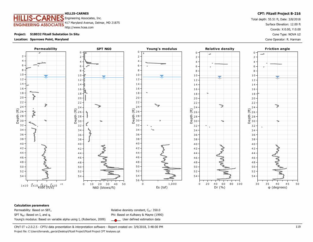
Project: S18032 Fitzell Substation In Situ
HILLIS-CARNES
Engineering Associates, Inc.
417 Maryland Avenue, Delmar, MD 21875
http://www.hcea.com
Total depth: 55.51 ft, Date: 3/8/2018
Surface Elevation: 12.00 ft
Sparrows Point, Maryland
Coords: X:0.00, Y:0.00
Cone Type: NOVA U2
Cone Operator: R. Harman
CPT: Fitzell Project B-216
Location:
Permeability
Ksbt (ft/s)1x10
-91x10
-61x10
-31x10
+0
Depth
(ft
)
54
52
50
48
46
44
42
40
38
36
34
32
30
28
26
24
22
20
18
16
14
12
10
8
6
4
2
Permeability Young's modulus
Es (tsf)1 ,0000
Depth
(ft
)
56
54
52
50
48
46
44
42
40
38
36
34
32
30
28
26
24
22
20
18
16
14
12
10
8
6
4
2
0Young's modulusSPT N60
N60 (blows/ft)50403020100
Depth
(ft
)
54
52
50
48
46
44
42
40
38
36
34
32
30
28
26
24
22
20
18
16
14
12
10
8
6
4
2
0
SPT N60 Relative density
Dr (%)100806040200
Depth
(ft
)
54
52
50
48
46
44
42
40
38
36
34
32
30
28
26
24
22
20
18
16
14
12
10
8
6
4
2
0
Relative density
Calculation parameters
Relative desnisty constant, CDr: 350.0Permeability: Based on SBTn
SPT N60: Based on Ic and qt
Young’s modulus: Based on variable alpha using Ic (Robertson, 2009)
Phi: Based on Kulhawy & Mayne (1990)
User defined estimation data
Friction angle
φ (degrees)5045403530
Depth
(ft
)
54
52
50
48
46
44
42
40
38
36
34
32
30
28
26
24
22
20
18
16
14
12
10
8
6
4
2
0
Friction angle
CPeT-IT v.2.0.2.5 - CPTU data presentation & interpretation software - Report created on: 3/9/2018, 3:48:00 PM 119
Project file: C:\Users\fernando_garcia\Desktop\Fitzell Project\Fitzell Project CPT Analyses.cpt
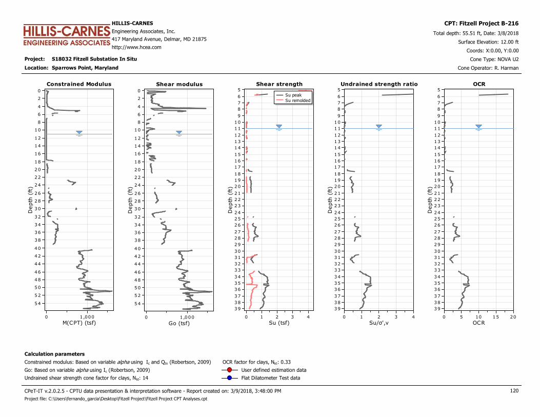
Project: S18032 Fitzell Substation In Situ
HILLIS-CARNES
Engineering Associates, Inc.
417 Maryland Avenue, Delmar, MD 21875
http://www.hcea.com
Total depth: 55.51 ft, Date: 3/8/2018
Surface Elevation: 12.00 ft
Sparrows Point, Maryland
Coords: X:0.00, Y:0.00
Cone Type: NOVA U2
Cone Operator: R. Harman
CPT: Fitzell Project B-216
Location:
Constrained Modulus
M(CPT) (tsf)1 ,0000
Depth
(ft
)
54
52
50
48
46
44
42
40
38
36
34
32
30
28
26
24
22
20
18
16
14
12
10
8
6
4
2
0
Constrained Modulus Shear strength
Su (tsf)43210
Depth
(ft
)
39
38
37
36
35
34
33
32
31
30
29
28
27
26
25
24
23
22
21
20
19
18
17
16
15
14
13
12
11
10
9
8
7
6
5Su peak
Su remolded
Shear strengthShear modulus
Go (tsf)1 ,0000
Depth
(ft
)
54
52
50
48
46
44
42
40
38
36
34
32
30
28
26
24
22
20
18
16
14
12
10
8
6
4
2
0
Shear modulus Undrained strength ratio
Su/σ',v43210
Depth
(ft
)
39
38
37
36
35
34
33
32
31
30
29
28
27
26
25
24
23
22
21
20
19
18
17
16
15
14
13
12
11
10
9
8
7
6
5
Undrained strength ratio OCR
OCR20151050
Depth
(ft
)
39
38
37
36
35
34
33
32
31
30
29
28
27
26
25
24
23
22
21
20
19
18
17
16
15
14
13
12
11
10
9
8
7
6
5
OCR
Calculation parameters
Undrained shear strength cone factor for clays, Nkt: 14
OCR factor for clays, Nkt: 0.33
Go: Based on variable alpha using Ic (Robertson, 2009)
Constrained modulus: Based on variable alpha using Ic and Qtn (Robertson, 2009)
User defined estimation data
Flat Dilatometer Test data
CPeT-IT v.2.0.2.5 - CPTU data presentation & interpretation software - Report created on: 3/9/2018, 3:48:00 PM 120
Project file: C:\Users\fernando_garcia\Desktop\Fitzell Project\Fitzell Project CPT Analyses.cpt
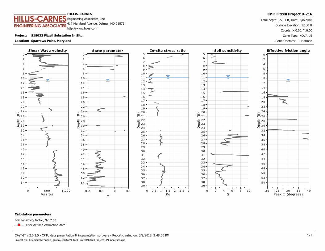
Project: S18032 Fitzell Substation In Situ
HILLIS-CARNES
Engineering Associates, Inc.
417 Maryland Avenue, Delmar, MD 21875
http://www.hcea.com
Total depth: 55.51 ft, Date: 3/8/2018
Surface Elevation: 12.00 ft
Sparrows Point, Maryland
Coords: X:0.00, Y:0.00
Cone Type: NOVA U2
Cone Operator: R. Harman
CPT: Fitzell Project B-216
Location:
Shear Wave velocity
Vs (ft/s)1 ,0005000
Depth
(ft
)
54
52
50
48
46
44
42
40
38
36
34
32
30
28
26
24
22
20
18
16
14
12
10
8
6
4
2
0
Shear Wave velocity In-situ stress ratio
Ko32 .521.510.50
Depth
(ft
)
39
38
37
36
35
34
33
32
31
30
29
28
27
26
25
24
23
22
21
20
19
18
17
16
15
14
13
12
11
10
9
8
7
6
5
In-situ stress ratioState parameter
ψ0.10-0 .1-0 .2
Depth
(ft
)
54
52
50
48
46
44
42
40
38
36
34
32
30
28
26
24
22
20
18
16
14
12
10
8
6
4
2
0
State parameter Soil sensitivity
S1086420
Depth
(ft
)
39
38
37
36
35
34
33
32
31
30
29
28
27
26
25
24
23
22
21
20
19
18
17
16
15
14
13
12
11
10
9
8
7
6
5
Soil sensitivity Effective friction angle
Peak φ (degrees)4035302520
Depth
(ft
)
54
52
50
48
46
44
42
40
38
36
34
32
30
28
26
24
22
20
18
16
14
12
10
8
6
4
2
0
Effective friction angle
Calculation parameters
Soil Sensitivity factor, NS: 7.00
User defined estimation data
CPeT-IT v.2.0.2.5 - CPTU data presentation & interpretation software - Report created on: 3/9/2018, 3:48:00 PM 121
Project file: C:\Users\fernando_garcia\Desktop\Fitzell Project\Fitzell Project CPT Analyses.cpt
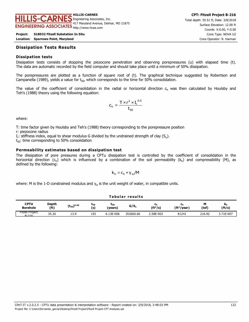
Project: S18032 Fitzell Substation In Situ
HILLIS-CARNES
Engineering Associates, Inc.
417 Maryland Avenue, Delmar, MD 21875
http://www.hcea.com
Total depth: 55.51 ft, Date: 3/8/2018
Surface Elevation: 12.00 ft
Sparrows Point, Maryland
Coords: X:0.00, Y:0.00
Cone Type: NOVA U2
Cone Operator: R. Harman
CPT: Fitzell Project B-216
Location:
CPTU
Borehole
Depth
(ft)(t50)0.50 t50
(s)
t50
(years)G/Su
ch
(ft2/s)
ch
(ft2/year)
T a bu l a r r e su l t s
Dissipation Tests Results
Dissipation tests consists of stopping the piezocone penetration and observing porepressures (u) with elapsed time (t).The data are automatic recorded by the field computer and should take place until a minimum of 50% dissipation. The porepressures are plotted as a function of square root of (t). The graphical technique suggested by Robertson andCampanella (1989), yields a value for t50, which corresponds to the time for 50% consolidation. The value of the coefficient of consolidation in the radial or horizontal direction ch was then calculated by Houlsby andTeh's (1988) theory using the following equation:
50
5.0
r2
ht
IrTc
××=
where: T: time factor given by Houlsby and Teh's (1988) theory corresponding to the porepressure positionr: piezocone radiusIr: stiffness index, equal to shear modulus G divided by the undrained strength of clay (Su).t50: time corresponding to 50% consolidation
Dissipation tests
Permeability estimates based on dissipation test
The dissipation of pore pressures during a CPTu dissipation test is controlled by the coefficient of consolidation in thehorizontal direction (ch) which is influenced by a combination of the soil permeability (kh) and compressibility (M), asdefined by the following:
/Mγck whh ×=
where: M is the 1-D constrained modulus and γw is the unit weight of water, in compatible units.
M
(tsf)
kh
(ft/s)
Fitzell Project
B-21635.20 13.9 193 6.13E-006 352660.66 2.58E-003 81241 216.92 3.71E-007
122
Project file: C:\Users\fernando_garcia\Desktop\Fitzell Project\Fitzell Project CPT Analyses.cpt
CPeT-IT v.2.0.2.5 - CPTU data presentation & interpretation software - Report created on: 3/9/2018, 3:48:03 PM
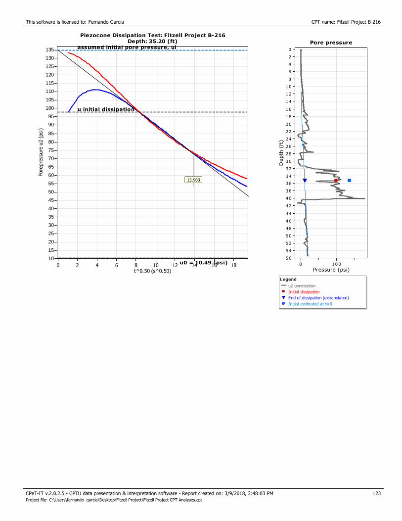
This software is licensed to: Fernando Garcia CPT name: Fitzell Project B-216
Piezocone Dissipation Test: Fitzell Project B-216Depth: 35.20 (ft)
t^0.50 (s^0.50)181614121086420
Pore
pre
ssure
u2 (
psi
)
135
130
125
120
115
110
105
100
95
90
85
80
75
70
65
60
55
50
45
40
35
30
25
20
15
10
13.903
Piezocone Dissipation Test: Fitzell Project B-216Depth: 35.20 (ft)
u0 = 10.49 (psi)
u initial dissipation
assumed initial pore pressure, uiPore pressure
Pressure (psi)1000
Depth
(ft
)
56
54
52
50
48
46
44
42
40
38
36
34
32
30
28
26
24
22
20
18
16
14
12
10
8
6
4
2
0
Legend
u2 penetration
Initial dissipation
End of dissipation (extrapolated)
Initial estimated at t=0
Pore pressure
123
Project file: C:\Users\fernando_garcia\Desktop\Fitzell Project\Fitzell Project CPT Analyses.cpt
CPeT-IT v.2.0.2.5 - CPTU data presentation & interpretation software - Report created on: 3/9/2018, 3:48:03 PM
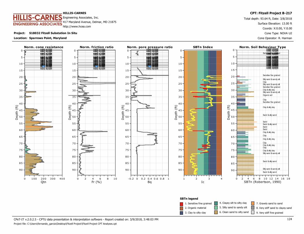
Project: S18032 Fitzell Substation In Situ
HILLIS-CARNES
Engineering Associates, Inc.
417 Maryland Avenue, Delmar, MD 21875
http://www.hcea.com
Total depth: 93.64 ft, Date: 3/8/2018
Surface Elevation: 13.00 ft
Sparrows Point, Maryland
Coords: X:0.00, Y:0.00
Cone Type: NOVA U2
Cone Operator: R. Harman
CPT: Fitzell Project B-217
Location:
Norm. cone resistanceHAND AUGERHAND AUGERHAND AUGERHAND AUGERHAND AUGERHAND AUGERHAND AUGERHAND AUGERHAND AUGERHAND AUGERHAND AUGERHAND AUGERHAND AUGERHAND AUGERHAND AUGERHAND AUGERHAND AUGERHAND AUGERHAND AUGERHAND AUGERHAND AUGERHAND AUGERHAND AUGERHAND AUGERHAND AUGERHAND AUGERHAND AUGERHAND AUGERHAND AUGERHAND AUGERHAND AUGERHAND AUGERHAND AUGERHAND AUGERHAND AUGER
Qtn4003002001000
Depth
(ft
)
90
85
80
75
70
65
60
55
50
45
40
35
30
25
20
15
10
5
0
Norm. cone resistance Norm. pore pressure ratioHAND AUGERHAND AUGERHAND AUGERHAND AUGERHAND AUGERHAND AUGERHAND AUGERHAND AUGERHAND AUGERHAND AUGERHAND AUGERHAND AUGERHAND AUGERHAND AUGERHAND AUGERHAND AUGERHAND AUGERHAND AUGERHAND AUGERHAND AUGERHAND AUGERHAND AUGERHAND AUGERHAND AUGERHAND AUGERHAND AUGERHAND AUGERHAND AUGERHAND AUGERHAND AUGERHAND AUGERHAND AUGERHAND AUGERHAND AUGERHAND AUGER
Bq10 .80 .60.40.20-0.2
Depth
(ft
)
90
85
80
75
70
65
60
55
50
45
40
35
30
25
20
15
10
5
0
Norm. pore pressure ratioNorm. friction ratioHAND AUGERHAND AUGERHAND AUGERHAND AUGERHAND AUGERHAND AUGERHAND AUGERHAND AUGERHAND AUGERHAND AUGERHAND AUGERHAND AUGERHAND AUGERHAND AUGERHAND AUGERHAND AUGERHAND AUGERHAND AUGERHAND AUGERHAND AUGERHAND AUGERHAND AUGERHAND AUGERHAND AUGERHAND AUGERHAND AUGERHAND AUGERHAND AUGERHAND AUGERHAND AUGERHAND AUGERHAND AUGERHAND AUGERHAND AUGERHAND AUGER
Fr (%)1086420
Depth
(ft
)
90
85
80
75
70
65
60
55
50
45
40
35
30
25
20
15
10
5
0
Norm. friction ratio SBTn Index
Ic4321
Depth
(ft
)
90
85
80
75
70
65
60
55
50
45
40
35
30
25
20
15
10
5
0
SBTn Index Norm. Soil Behaviour TypeHAND AUGERHAND AUGERHAND AUGERHAND AUGERHAND AUGERHAND AUGERHAND AUGERHAND AUGERHAND AUGERHAND AUGERHAND AUGERHAND AUGERHAND AUGERHAND AUGERHAND AUGERHAND AUGERHAND AUGERHAND AUGERHAND AUGERHAND AUGERHAND AUGERHAND AUGERHAND AUGERHAND AUGERHAND AUGERHAND AUGERHAND AUGERHAND AUGERHAND AUGERHAND AUGERHAND AUGERHAND AUGERHAND AUGERHAND AUGERHAND AUGER
SBTn (Robertson, 1990)181614121086420
Depth
(ft
)
90
85
80
75
70
65
60
55
50
45
40
35
30
25
20
15
10
5
0Norm. Soil Behaviour Type
Sensitive fine grained
Sensitive fine grained
Silty sand & sandy silt
ClaySilty sand & sandy silt
Sensitive fine grained
Clay & silty claySilty sand & sandy silt
Organic soil
ClaySensitive fine grained
Clay & silty clay
Sand & silty sand
SandSand & silty sand
SandSand
Clay & silty clay
Clay
Clay & silty clay
ClayClay & silty clayClay
Clay & silty clay
Silty sand & sandy silt
Sand & silty sand
Silty sand & sandy silt
Sand & silty sand
SBTn legend
1. Sensitive fine grained
2. Organic material
3. Clay to silty clay
4. Clayey silt to silty clay
5. Silty sand to sandy silt
6. Clean sand to silty sand
7. Gravely sand to sand
8. Very stiff sand to clayey sand
9. Very stiff fine grained
CPeT-IT v.2.0.2.5 - CPTU data presentation & interpretation software - Report created on: 3/9/2018, 3:48:03 PM 124
Project file: C:\Users\fernando_garcia\Desktop\Fitzell Project\Fitzell Project CPT Analyses.cpt

Project: S18032 Fitzell Substation In Situ
HILLIS-CARNES
Engineering Associates, Inc.
417 Maryland Avenue, Delmar, MD 21875
http://www.hcea.com
Total depth: 93.64 ft, Date: 3/8/2018
Surface Elevation: 13.00 ft
Sparrows Point, Maryland
Coords: X:0.00, Y:0.00
Cone Type: NOVA U2
Cone Operator: R. Harman
CPT: Fitzell Project B-217
Location:
Norm. cone resistanceHAND AUGERHAND AUGERHAND AUGERHAND AUGERHAND AUGERHAND AUGERHAND AUGERHAND AUGERHAND AUGERHAND AUGERHAND AUGERHAND AUGERHAND AUGERHAND AUGERHAND AUGERHAND AUGERHAND AUGERHAND AUGERHAND AUGERHAND AUGERHAND AUGERHAND AUGERHAND AUGERHAND AUGERHAND AUGERHAND AUGERHAND AUGERHAND AUGERHAND AUGERHAND AUGERHAND AUGERHAND AUGERHAND AUGERHAND AUGERHAND AUGER
Qtn4003002001000
Depth
(ft
)
90
85
80
75
70
65
60
55
50
45
40
35
30
25
20
15
10
5
0
Norm. cone resistance Norm. Pore PressureHAND AUGERHAND AUGERHAND AUGERHAND AUGERHAND AUGERHAND AUGERHAND AUGERHAND AUGERHAND AUGERHAND AUGERHAND AUGERHAND AUGERHAND AUGERHAND AUGERHAND AUGERHAND AUGERHAND AUGERHAND AUGERHAND AUGERHAND AUGERHAND AUGERHAND AUGERHAND AUGERHAND AUGERHAND AUGERHAND AUGERHAND AUGERHAND AUGERHAND AUGERHAND AUGERHAND AUGERHAND AUGERHAND AUGERHAND AUGERHAND AUGER
U21086420-2
Depth
(ft
)
90
85
80
75
70
65
60
55
50
45
40
35
30
25
20
15
10
5
0
Norm. Pore PressureNorm. friction ratioHAND AUGERHAND AUGERHAND AUGERHAND AUGERHAND AUGERHAND AUGERHAND AUGERHAND AUGERHAND AUGERHAND AUGERHAND AUGERHAND AUGERHAND AUGERHAND AUGERHAND AUGERHAND AUGERHAND AUGERHAND AUGERHAND AUGERHAND AUGERHAND AUGERHAND AUGERHAND AUGERHAND AUGERHAND AUGERHAND AUGERHAND AUGERHAND AUGERHAND AUGERHAND AUGERHAND AUGERHAND AUGERHAND AUGERHAND AUGERHAND AUGER
Fr (%)1086420
Depth
(ft
)
90
85
80
75
70
65
60
55
50
45
40
35
30
25
20
15
10
5
0
Norm. friction ratio Mod. SBTn I(B)HAND AUGERHAND AUGERHAND AUGERHAND AUGERHAND AUGERHAND AUGERHAND AUGERHAND AUGERHAND AUGERHAND AUGERHAND AUGERHAND AUGERHAND AUGERHAND AUGERHAND AUGERHAND AUGERHAND AUGERHAND AUGERHAND AUGERHAND AUGERHAND AUGERHAND AUGERHAND AUGERHAND AUGERHAND AUGERHAND AUGERHAND AUGERHAND AUGERHAND AUGERHAND AUGERHAND AUGERHAND AUGERHAND AUGERHAND AUGERHAND AUGER
IB
10100
Depth
(ft
)
90
85
80
75
70
65
60
55
50
45
40
35
30
25
20
15
10
5
0
Mod. SBTn I(B)
2232
Mod. Norm. SBTnHAND AUGERHAND AUGERHAND AUGERHAND AUGERHAND AUGERHAND AUGERHAND AUGERHAND AUGERHAND AUGERHAND AUGERHAND AUGERHAND AUGERHAND AUGERHAND AUGERHAND AUGERHAND AUGERHAND AUGERHAND AUGERHAND AUGERHAND AUGERHAND AUGERHAND AUGERHAND AUGERHAND AUGERHAND AUGERHAND AUGERHAND AUGERHAND AUGERHAND AUGERHAND AUGERHAND AUGERHAND AUGERHAND AUGERHAND AUGERHAND AUGER
Mod. SBTn (Robertson 2016)181614121086420
Depth
(ft
)
90
85
80
75
70
65
60
55
50
45
40
35
30
25
20
15
10
5
0Mod. Norm. SBTn
Clay-like - Contractive - Sensitive
Transitional - Contractive
Clay-like - ContractiveSand-like - Contractive
Sand-like - ContractiveClay-like - Contractive - SensitiveSand-like - ContractiveClay-like - Contractive - SensitiveTransitional - Contractive
Clay-like - Contractive - Sensitive
Clay-like - Contractive - Sensitive
Clay-like - Contractive - Sensitive
Transitional - Contractive
Sand like - Dilative
Transitional - DilativeClay-like - Contractive - Sensitive
Clay-like - Contractive - Sensitive
Transitional - ContractiveClay-like - Dilative
Transitional - DilativeTransitional - Contractive
Sand like - Dilative
Sand-like - Contractive
Sand like - Dilative
Sand-like - Contractive
Sand like - Dilative
Mod. SBTn legend
1. CCS: ClayLike - Contractive, Sensitive
2. CC: Clay-like - Contractive
3. CD: Clay-Like: Dilative
4. TC: Transitional - Contractive
5. TD: Transitional - Dilative
6. SC: Sand-like - Contractive
7. SD: Sand-like - Dilative
CPeT-IT v.2.0.2.5 - CPTU data presentation & interpretation software - Report created on: 3/9/2018, 3:48:04 PM 125
Project file: C:\Users\fernando_garcia\Desktop\Fitzell Project\Fitzell Project CPT Analyses.cpt
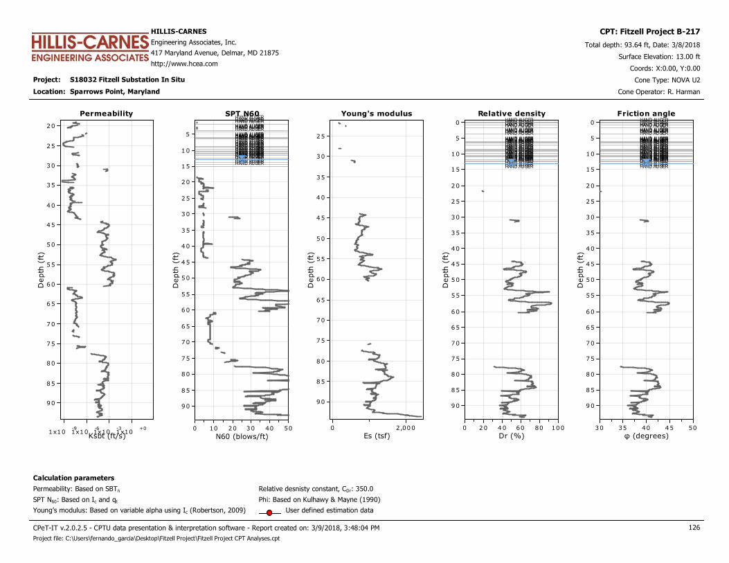
Project: S18032 Fitzell Substation In Situ
HILLIS-CARNES
Engineering Associates, Inc.
417 Maryland Avenue, Delmar, MD 21875
http://www.hcea.com
Total depth: 93.64 ft, Date: 3/8/2018
Surface Elevation: 13.00 ft
Sparrows Point, Maryland
Coords: X:0.00, Y:0.00
Cone Type: NOVA U2
Cone Operator: R. Harman
CPT: Fitzell Project B-217
Location:
Permeability
Ksbt (ft/s)1x10
-91x10
-61x10
-31x10
+0
Depth
(ft
)
90
85
80
75
70
65
60
55
50
45
40
35
30
25
20
Permeability Young's modulus
Es (tsf)2,0000
Depth
(ft
)
90
85
80
75
70
65
60
55
50
45
40
35
30
25
Young's modulusSPT N60HAND AUGERHAND AUGERHAND AUGERHAND AUGERHAND AUGERHAND AUGERHAND AUGERHAND AUGERHAND AUGERHAND AUGERHAND AUGERHAND AUGERHAND AUGERHAND AUGERHAND AUGERHAND AUGERHAND AUGERHAND AUGERHAND AUGERHAND AUGERHAND AUGERHAND AUGERHAND AUGERHAND AUGERHAND AUGERHAND AUGERHAND AUGERHAND AUGERHAND AUGERHAND AUGERHAND AUGERHAND AUGERHAND AUGERHAND AUGER
N60 (blows/ft)50403020100
Depth
(ft
)
90
85
80
75
70
65
60
55
50
45
40
35
30
25
20
15
10
5
SPT N60 Relative densityHAND AUGERHAND AUGERHAND AUGERHAND AUGERHAND AUGERHAND AUGERHAND AUGERHAND AUGERHAND AUGERHAND AUGERHAND AUGERHAND AUGERHAND AUGERHAND AUGERHAND AUGERHAND AUGERHAND AUGERHAND AUGERHAND AUGERHAND AUGERHAND AUGERHAND AUGERHAND AUGERHAND AUGERHAND AUGERHAND AUGERHAND AUGERHAND AUGERHAND AUGERHAND AUGERHAND AUGERHAND AUGERHAND AUGERHAND AUGERHAND AUGER
Dr (%)100806040200
Depth
(ft
)
90
85
80
75
70
65
60
55
50
45
40
35
30
25
20
15
10
5
0
Relative density
Calculation parameters
Relative desnisty constant, CDr: 350.0Permeability: Based on SBTn
SPT N60: Based on Ic and qt
Young’s modulus: Based on variable alpha using Ic (Robertson, 2009)
Phi: Based on Kulhawy & Mayne (1990)
User defined estimation data
Friction angleHAND AUGERHAND AUGERHAND AUGERHAND AUGERHAND AUGERHAND AUGERHAND AUGERHAND AUGERHAND AUGERHAND AUGERHAND AUGERHAND AUGERHAND AUGERHAND AUGERHAND AUGERHAND AUGERHAND AUGERHAND AUGERHAND AUGERHAND AUGERHAND AUGERHAND AUGERHAND AUGERHAND AUGERHAND AUGERHAND AUGERHAND AUGERHAND AUGERHAND AUGERHAND AUGERHAND AUGERHAND AUGERHAND AUGERHAND AUGERHAND AUGER
φ (degrees)5045403530
Depth
(ft
)
90
85
80
75
70
65
60
55
50
45
40
35
30
25
20
15
10
5
0
Friction angle
CPeT-IT v.2.0.2.5 - CPTU data presentation & interpretation software - Report created on: 3/9/2018, 3:48:04 PM 126
Project file: C:\Users\fernando_garcia\Desktop\Fitzell Project\Fitzell Project CPT Analyses.cpt
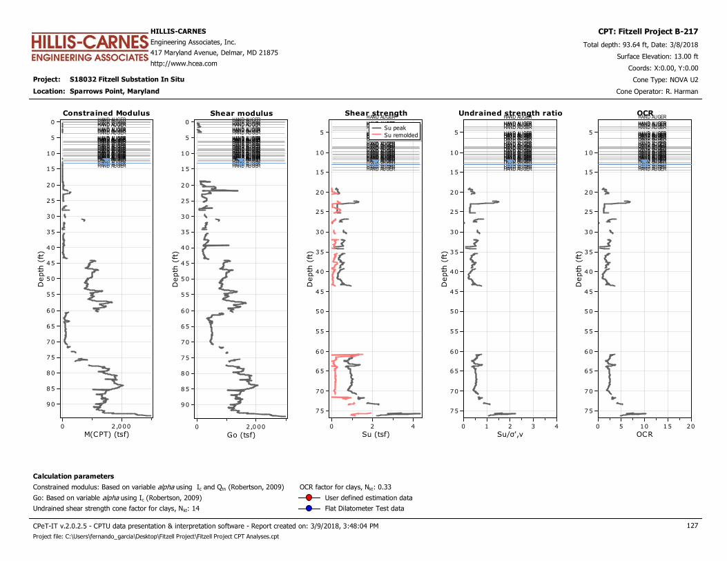
Project: S18032 Fitzell Substation In Situ
HILLIS-CARNES
Engineering Associates, Inc.
417 Maryland Avenue, Delmar, MD 21875
http://www.hcea.com
Total depth: 93.64 ft, Date: 3/8/2018
Surface Elevation: 13.00 ft
Sparrows Point, Maryland
Coords: X:0.00, Y:0.00
Cone Type: NOVA U2
Cone Operator: R. Harman
CPT: Fitzell Project B-217
Location:
Constrained ModulusHAND AUGERHAND AUGERHAND AUGERHAND AUGERHAND AUGERHAND AUGERHAND AUGERHAND AUGERHAND AUGERHAND AUGERHAND AUGERHAND AUGERHAND AUGERHAND AUGERHAND AUGERHAND AUGERHAND AUGERHAND AUGERHAND AUGERHAND AUGERHAND AUGERHAND AUGERHAND AUGERHAND AUGERHAND AUGERHAND AUGERHAND AUGERHAND AUGERHAND AUGERHAND AUGERHAND AUGERHAND AUGERHAND AUGERHAND AUGERHAND AUGER
M(CPT) (tsf)2 ,0000
Depth
(ft
)
90
85
80
75
70
65
60
55
50
45
40
35
30
25
20
15
10
5
0
Constrained Modulus Shear strengthHAND AUGER
HAND AUGERHAND AUGERHAND AUGERHAND AUGERHAND AUGERHAND AUGERHAND AUGERHAND AUGERHAND AUGERHAND AUGERHAND AUGERHAND AUGERHAND AUGERHAND AUGERHAND AUGERHAND AUGERHAND AUGERHAND AUGERHAND AUGERHAND AUGERHAND AUGERHAND AUGERHAND AUGERHAND AUGERHAND AUGERHAND AUGERHAND AUGERHAND AUGERHAND AUGERHAND AUGERHAND AUGER
Su (tsf)420
Depth
(ft
)
75
70
65
60
55
50
45
40
35
30
25
20
15
10
5Su peak
Su remolded
Shear strengthShear modulusHAND AUGERHAND AUGERHAND AUGERHAND AUGERHAND AUGERHAND AUGERHAND AUGERHAND AUGERHAND AUGERHAND AUGERHAND AUGERHAND AUGERHAND AUGERHAND AUGERHAND AUGERHAND AUGERHAND AUGERHAND AUGERHAND AUGERHAND AUGERHAND AUGERHAND AUGERHAND AUGERHAND AUGERHAND AUGERHAND AUGERHAND AUGERHAND AUGERHAND AUGERHAND AUGERHAND AUGERHAND AUGERHAND AUGERHAND AUGERHAND AUGER
Go (tsf)2,0000
Depth
(ft
)
90
85
80
75
70
65
60
55
50
45
40
35
30
25
20
15
10
5
0
Shear modulus Undrained strength ratioHAND AUGER
HAND AUGERHAND AUGERHAND AUGERHAND AUGERHAND AUGERHAND AUGERHAND AUGERHAND AUGERHAND AUGERHAND AUGERHAND AUGERHAND AUGERHAND AUGERHAND AUGERHAND AUGERHAND AUGERHAND AUGERHAND AUGERHAND AUGERHAND AUGERHAND AUGERHAND AUGERHAND AUGERHAND AUGERHAND AUGERHAND AUGERHAND AUGERHAND AUGERHAND AUGERHAND AUGERHAND AUGER
Su/σ',v43210
Depth
(ft
)
75
70
65
60
55
50
45
40
35
30
25
20
15
10
5
Undrained strength ratio OCRHAND AUGER
HAND AUGERHAND AUGERHAND AUGERHAND AUGERHAND AUGERHAND AUGERHAND AUGERHAND AUGERHAND AUGERHAND AUGERHAND AUGERHAND AUGERHAND AUGERHAND AUGERHAND AUGERHAND AUGERHAND AUGERHAND AUGERHAND AUGERHAND AUGERHAND AUGERHAND AUGERHAND AUGERHAND AUGERHAND AUGERHAND AUGERHAND AUGERHAND AUGERHAND AUGERHAND AUGERHAND AUGER
OCR20151050
Depth
(ft
)
75
70
65
60
55
50
45
40
35
30
25
20
15
10
5
OCR
Calculation parameters
Undrained shear strength cone factor for clays, Nkt: 14
OCR factor for clays, Nkt: 0.33
Go: Based on variable alpha using Ic (Robertson, 2009)
Constrained modulus: Based on variable alpha using Ic and Qtn (Robertson, 2009)
User defined estimation data
Flat Dilatometer Test data
CPeT-IT v.2.0.2.5 - CPTU data presentation & interpretation software - Report created on: 3/9/2018, 3:48:04 PM 127
Project file: C:\Users\fernando_garcia\Desktop\Fitzell Project\Fitzell Project CPT Analyses.cpt
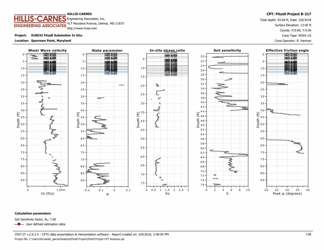
Project: S18032 Fitzell Substation In Situ
HILLIS-CARNES
Engineering Associates, Inc.
417 Maryland Avenue, Delmar, MD 21875
http://www.hcea.com
Total depth: 93.64 ft, Date: 3/8/2018
Surface Elevation: 13.00 ft
Sparrows Point, Maryland
Coords: X:0.00, Y:0.00
Cone Type: NOVA U2
Cone Operator: R. Harman
CPT: Fitzell Project B-217
Location:
Shear Wave velocityHAND AUGERHAND AUGERHAND AUGERHAND AUGERHAND AUGERHAND AUGERHAND AUGERHAND AUGERHAND AUGERHAND AUGERHAND AUGERHAND AUGERHAND AUGERHAND AUGERHAND AUGERHAND AUGERHAND AUGERHAND AUGERHAND AUGERHAND AUGERHAND AUGERHAND AUGERHAND AUGERHAND AUGERHAND AUGERHAND AUGERHAND AUGERHAND AUGERHAND AUGERHAND AUGERHAND AUGERHAND AUGERHAND AUGERHAND AUGERHAND AUGER
Vs (ft/s)1,0000
Depth
(ft
)
90
85
80
75
70
65
60
55
50
45
40
35
30
25
20
15
10
5
0
Shear Wave velocity In-situ stress ratioHAND AUGER
HAND AUGERHAND AUGERHAND AUGERHAND AUGERHAND AUGERHAND AUGERHAND AUGERHAND AUGERHAND AUGERHAND AUGERHAND AUGERHAND AUGERHAND AUGERHAND AUGERHAND AUGERHAND AUGERHAND AUGERHAND AUGERHAND AUGERHAND AUGERHAND AUGERHAND AUGERHAND AUGERHAND AUGERHAND AUGERHAND AUGERHAND AUGERHAND AUGERHAND AUGERHAND AUGERHAND AUGER
Ko32 .521.510.50
Depth
(ft
)
75
70
65
60
55
50
45
40
35
30
25
20
15
10
5
In-situ stress ratioState parameterHAND AUGERHAND AUGERHAND AUGERHAND AUGERHAND AUGERHAND AUGERHAND AUGERHAND AUGERHAND AUGERHAND AUGERHAND AUGERHAND AUGERHAND AUGERHAND AUGERHAND AUGERHAND AUGERHAND AUGERHAND AUGERHAND AUGERHAND AUGERHAND AUGERHAND AUGERHAND AUGERHAND AUGERHAND AUGERHAND AUGERHAND AUGERHAND AUGERHAND AUGERHAND AUGERHAND AUGERHAND AUGERHAND AUGERHAND AUGERHAND AUGER
ψ0.10-0 .1-0 .2
Depth
(ft
)
90
85
80
75
70
65
60
55
50
45
40
35
30
25
20
15
10
5
0
State parameter Soil sensitivity
S1086420
Depth
(ft
)
76
74
72
70
68
66
64
62
60
58
56
54
52
50
48
46
44
42
40
38
36
34
32
30
28
26
24
22
20
Soil sensitivity Effective friction angleHAND AUGERHAND AUGERHAND AUGERHAND AUGERHAND AUGERHAND AUGERHAND AUGERHAND AUGERHAND AUGERHAND AUGERHAND AUGERHAND AUGERHAND AUGERHAND AUGERHAND AUGERHAND AUGERHAND AUGERHAND AUGERHAND AUGERHAND AUGERHAND AUGERHAND AUGERHAND AUGERHAND AUGERHAND AUGERHAND AUGERHAND AUGERHAND AUGERHAND AUGERHAND AUGERHAND AUGERHAND AUGERHAND AUGERHAND AUGERHAND AUGER
Peak φ (degrees)4035302520
Depth
(ft
)
90
85
80
75
70
65
60
55
50
45
40
35
30
25
20
15
10
5
0
Effective friction angle
Calculation parameters
Soil Sensitivity factor, NS: 7.00
User defined estimation data
CPeT-IT v.2.0.2.5 - CPTU data presentation & interpretation software - Report created on: 3/9/2018, 3:48:04 PM 128
Project file: C:\Users\fernando_garcia\Desktop\Fitzell Project\Fitzell Project CPT Analyses.cpt
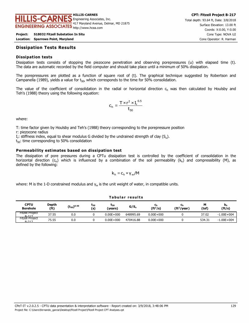
Project: S18032 Fitzell Substation In Situ
HILLIS-CARNES
Engineering Associates, Inc.
417 Maryland Avenue, Delmar, MD 21875
http://www.hcea.com
Total depth: 93.64 ft, Date: 3/8/2018
Surface Elevation: 13.00 ft
Sparrows Point, Maryland
Coords: X:0.00, Y:0.00
Cone Type: NOVA U2
Cone Operator: R. Harman
CPT: Fitzell Project B-217
Location:
CPTU
Borehole
Depth
(ft)(t50)0.50 t50
(s)
t50
(years)G/Su
ch
(ft2/s)
ch
(ft2/year)
T a bu l a r r e su l t s
Dissipation Tests Results
Dissipation tests consists of stopping the piezocone penetration and observing porepressures (u) with elapsed time (t).The data are automatic recorded by the field computer and should take place until a minimum of 50% dissipation. The porepressures are plotted as a function of square root of (t). The graphical technique suggested by Robertson andCampanella (1989), yields a value for t50, which corresponds to the time for 50% consolidation. The value of the coefficient of consolidation in the radial or horizontal direction ch was then calculated by Houlsby andTeh's (1988) theory using the following equation:
50
5.0
r2
ht
IrTc
××=
where: T: time factor given by Houlsby and Teh's (1988) theory corresponding to the porepressure positionr: piezocone radiusIr: stiffness index, equal to shear modulus G divided by the undrained strength of clay (Su).t50: time corresponding to 50% consolidation
Dissipation tests
Permeability estimates based on dissipation test
The dissipation of pore pressures during a CPTu dissipation test is controlled by the coefficient of consolidation in thehorizontal direction (ch) which is influenced by a combination of the soil permeability (kh) and compressibility (M), asdefined by the following:
/Mγck whh ×=
where: M is the 1-D constrained modulus and γw is the unit weight of water, in compatible units.
M
(tsf)
kh
(ft/s)
Fitzell Project
B-21737.55 0.0 0 0.00E+000 648995.69 0.00E+000 0 37.02 -1.00E+004
Fitzell Project
B-21775.55 0.0 0 0.00E+000 470416.88 0.00E+000 0 534.31 -1.00E+004
129
Project file: C:\Users\fernando_garcia\Desktop\Fitzell Project\Fitzell Project CPT Analyses.cpt
CPeT-IT v.2.0.2.5 - CPTU data presentation & interpretation software - Report created on: 3/9/2018, 3:48:06 PM
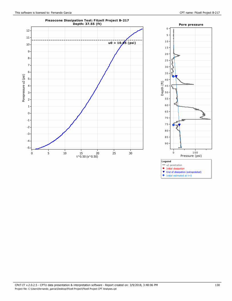
This software is licensed to: Fernando Garcia CPT name: Fitzell Project B-217
Piezocone Dissipation Test: Fitzell Project B-217Depth: 37.55 (ft)
t^0.50 (s^0.50)302520151050
Pore
pre
ssure
u2 (
psi
)
12
11
10
9
8
7
6
5
4
3
2
1
0
-1
-2
-3
-4
-5
Piezocone Dissipation Test: Fitzell Project B-217Depth: 37.55 (ft)
u0 = 10.65 (psi)
Pore pressure
Pressure (psi)1000
Depth
(ft
)
90
85
80
75
70
65
60
55
50
45
40
35
30
25
20
15
10
5
0
Legend
u2 penetration
Initial dissipation
End of dissipation (extrapolated)
Initial estimated at t=0
Pore pressure
130
Project file: C:\Users\fernando_garcia\Desktop\Fitzell Project\Fitzell Project CPT Analyses.cpt
CPeT-IT v.2.0.2.5 - CPTU data presentation & interpretation software - Report created on: 3/9/2018, 3:48:06 PM
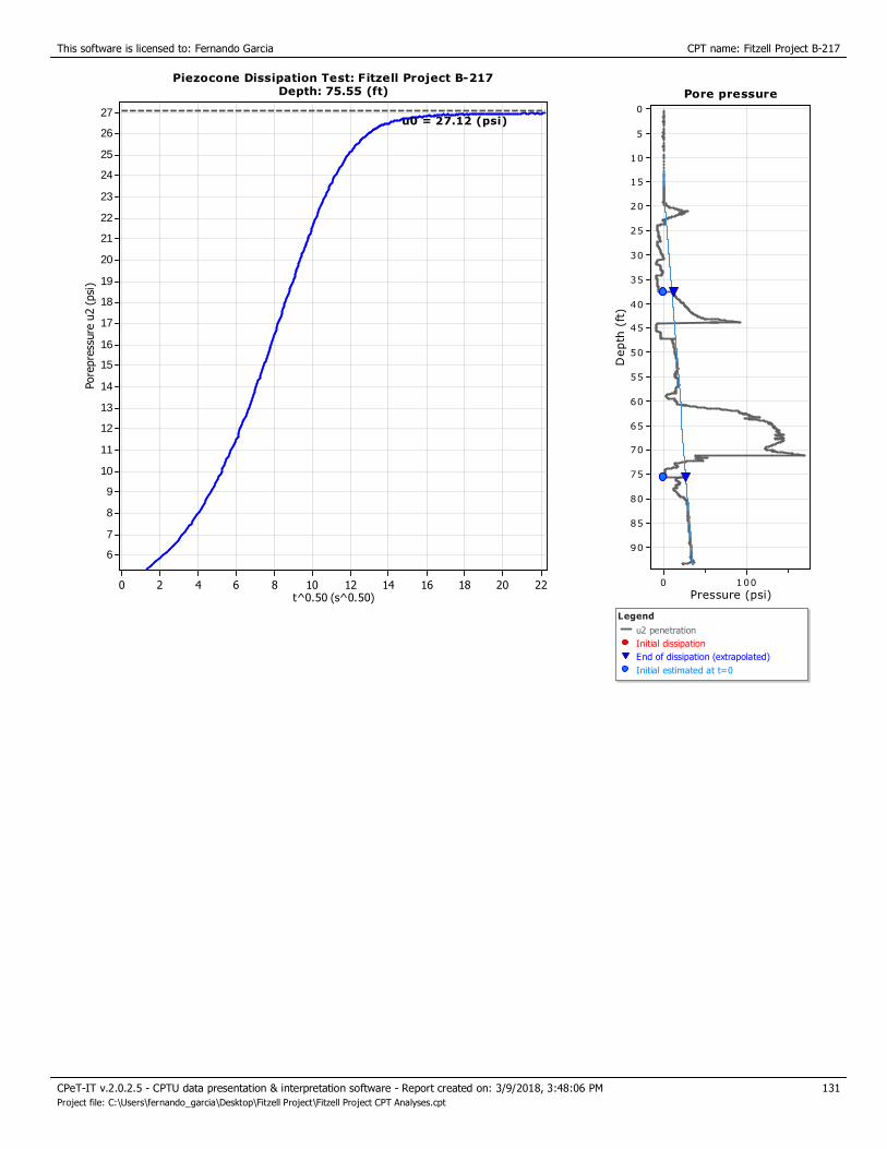
This software is licensed to: Fernando Garcia CPT name: Fitzell Project B-217
Piezocone Dissipation Test: Fitzell Project B-217Depth: 75.55 (ft)
t^0.50 (s^0.50)2220181614121086420
Pore
pre
ssure
u2 (
psi
)
27
26
25
24
23
22
21
20
19
18
17
16
15
14
13
12
11
10
9
8
7
6
Piezocone Dissipation Test: Fitzell Project B-217Depth: 75.55 (ft)
u0 = 27.12 (psi)
Pore pressure
Pressure (psi)1000
Depth
(ft
)
90
85
80
75
70
65
60
55
50
45
40
35
30
25
20
15
10
5
0
Legend
u2 penetration
Initial dissipation
End of dissipation (extrapolated)
Initial estimated at t=0
Pore pressure
131
Project file: C:\Users\fernando_garcia\Desktop\Fitzell Project\Fitzell Project CPT Analyses.cpt
CPeT-IT v.2.0.2.5 - CPTU data presentation & interpretation software - Report created on: 3/9/2018, 3:48:06 PM

APPENDIX E
Blank Field Sheets for NAPL Recovery Testing
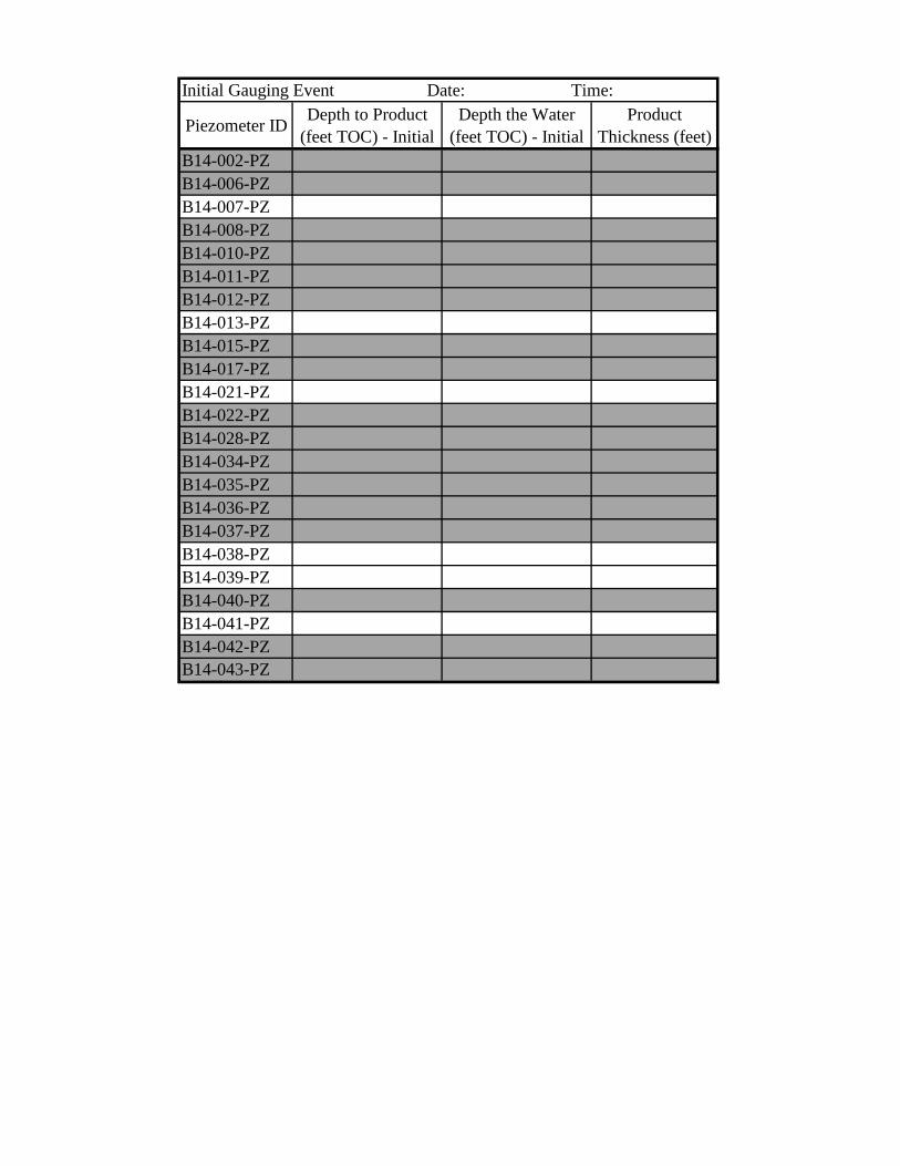
Piezometer ID Depth to Product (feet TOC) - Initial
Depth the Water (feet TOC) - Initial
Product Thickness (feet)
B14-002-PZB14-006-PZB14-007-PZB14-008-PZB14-010-PZB14-011-PZB14-012-PZB14-013-PZB14-015-PZB14-017-PZB14-021-PZB14-022-PZB14-028-PZB14-034-PZB14-035-PZB14-036-PZB14-037-PZB14-038-PZB14-039-PZB14-040-PZB14-041-PZB14-042-PZB14-043-PZ
Initial Gauging Event Date: Time:
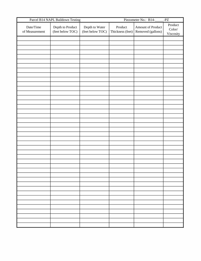
Date/Time of Measurement
Depth to Product (feet below TOC)
Depth to Water (feet below TOC)
Product Thickness (feet)
Amount of Product Removed (gallons)
ProductColor/
Viscosity
Parcel B14 NAPL Baildown Testing Piezometer No.: B14-_____-PZ