draft regulation on automatic emergency braking system€¦ · · 2009-09-16draft regulation on...
TRANSCRIPT

Transmitted by the expert from Japan AEBS/LDWS-01-05
090615
1
1st meeting of GRRF informal group on Automatic Emergency Braking and Lane Departure Warning Systems
Pari, 25-26 June 2009
Items 6.3 to 6.5 of the agenda
DRAFT REGULATION ON AUTOMATIC EMERGENCY BRAKING SYSTEM
The text reproduced below was prepared by the expert from Japan in order to insert Automatic Emergency
Braking Systems (AEBS) into the 1958 Agreement as a new Regulation.
Transmitted by the expert from Japan AEBS/LDWS-01-05
090615
2
DRAFT REGULATION ON AUTOMATIC EMERGENCY BRAKING SYSTEMS
CONTENTS – to be finalized REGULATION Page 1. Scope ............................................................................................................................. 2. Definitions ..................................................................................................................... 3. Application for approval 4. Approval ........................................................................................................................ 5. Specifications ................................................................................................................ 6. Tests ............................................................................................................................... 7. Modification of vehicle type and extension of approval ............................................... 8. Conformity of production .............................................................................................. 9. Penalties for non-conformity of production .................................................................. 10. Production definitely discontinued ................................................................................ 11. Names and addresses of Technical Services
responsible for conducting approval tests, and of Administrative Departments ...............................................................................
12. Introductory provisions
ANNEXES Annex 1: Communication Annex 2: Arrangements of approval marks Annex 3: Test procedures for stationary obstacle

Transmitted by the expert from Japan AEBS/LDWS-01-05
090615
3
Annex 4: Test procedures for moving obstacle Annex 5: Functioning test of the malfunction warning device of AEBS
Annex 6: Data processing for AEBS
Transmitted by the expert from Japan AEBS/LDWS-01-05
090615
4
1. SCOPE
This regulation applies to type approval of the vehicles of categories [M2,M3,N2,N3] *with regard to the Automatic Emergency Braking Systems defined in paragraph 2.3. At the time of application of this Regulation, Contracting Parties shall declare that they intend to mandate the installation of AEBS specified in this regulation in their territory for which category of vehicles. *: This vehicle of categories shows the proposal of EC. This issue will be discussed in future
in the informal meeting and GRRF.
2. DEFINITIONS For the purposes of this Regulation, 2.1. "Approval of a vehicle" means the approval of a vehicle type with regard to
AEBS; 2.2. "Vehicle type" means a category of vehicles which do not differ in such essential
respects as: 2.2.1. in the case of power-driven vehicle, 2.2.1.1. the vehicle category, (see paragraph 1. above); 2.2.1.2. the maximum mass, as defined in paragraph 2.18. below; 2.2.1.3. the distribution of mass among the axles; 2.2.1.4. the maximum design speed; 2.2.1.5. a different type of braking equipment, with more particular reference to the
presence or otherwise of equipment for braking a trailer, or any presence of an electric regenerative braking system;
2.2.1.6. the number and arrangement of the axles;

Transmitted by the expert from Japan AEBS/LDWS-01-05
090615
5
2.2.1.7. the engine type; 2.2.1.8. the number and ratios of gears; 2.2.1.9. the final drive ratios; 2.2.1.10. the tyre dimensions; 2.3. "Automatic Emergency Braking Systems (hereafter AEBS)" means a braking
system which has functions of the collision warning and the emergency event preparation to the driver in case of occurrence of a danger of collision with a forward obstacle and a function of the braking control for mitigating the damage of vehicle collision with a forward obstacle in case of a collision judged imminent or unavoidable.
2.4. "Vehicle with AEBS" means a vehicle equipped with AEBS. 2.5. "Forward obstacle" means a stationary or moving vehicle existing forward to the
vehicle with AEBS in the course of its progress and may collide with it. However, vehicles in the opposite lane may be excluded.
2.6. "Relative speed (here after Vr)" means the relative speed between the vehicle with
AEBS and the forward obstacle.
2.7. "Time to collision (here after TTC)" means the time to collision is defined as the estimated time that it will take the vehicle with AEBS to collide with the forward obstacle assuming the current relative speed remains constant.
2.8. "Collision avoidable limit line by braking" means a line showing the minimum TTC during which the vehicle's collision with a forward obstacle can be avoided by braking, plotted against the relative speed (on the Vr – TTC graph).
2.9. "Collision avoidable limit line by steering" means a line showing the minimum TTC during which the vehicle's collision with a forward obstacle can be avoided by steering, plotted against the relative speed (on the Vr – TTC graph).
2.10. "Collision judgment" means a state of a judgment that a collision cannot be avoided physically.
Transmitted by the expert from Japan AEBS/LDWS-01-05
090615
6
2.11. "Collision judgment line" means a line that connects the collision avoidable limit
line by braking or the collision avoidable limit line by steering, whichever be situated lower (on the Vr – TTC graph).
2.12. "Lower limit line for collision avoidance by normal braking" means the lower limit line of the distribution of normal braking start timing data for avoidance of a collision expressed by the TTC during the normal driving, plotted against the relative speed (on the Vr – TTC graph).
2.13. "Lower limit line for collision avoidance by normal steering" means the lower limit line of the distribution of normal steering start timing data expressed by the TTC during the daily driving, plotted against the relative speed (on the Vr – TTC graph).
2.14. "Collision risk judgment" means a state that has the high risk of a collision. 2.15. "Collision risk judgment line" means a line that connects the lower limit line of
collision avoidance by normal braking or the lower limit line of collision avoidance by normal steering, whichever be situated lower (on the Vr – TTC graph).
2.16. "Collision warning" means a function that makes the driver aware of a risk of collision in advance and prompts him to make an avoidance action.
2.17. "Emergency event preparation" means a function that notices the driver in advance that the system judges an unavoidable collision and starts the function of braking control.
2.18. "Lateral distance for collision avoidance" is the lateral movement required for the vehicle with AEBS to avoid collision with the forward obstacle.
2.19. "Overlapping ratio" means the ratio of overlapping width between vehicle with AEBS and forward obstacle divided by the width of the vehicle. Consequently the product of the overlapping ratio and the vehicle width gives the lateral distance for collision avoidance.
2.20. "Laden" means a state that the test vehicle is so laden as to attain its "maximum

Transmitted by the expert from Japan AEBS/LDWS-01-05
090615
7
mass".
2.21. "Unladen" means a state that the weight of the test vehicle is equal to its vehicle weight.
2.22. "Average deceleration" means the mean deceleration calculated in the section of a
time. 2.23. "Shortest braking distance" means the shortest distance in which the vehicle
travels from the instant the brake system is operated by the driver as prescribed in paragraph 3.4. until the stop of the vehicle.
2.24. "Maximum deceleration" means the maximum decelerations in a certain length of
time. 2.25. "Collision warning braking" means a brake operation that causes a maximum
deceleration of 0.98 m/s2 to 2.45 m/s2 and continues for less than 0.8 seconds. 3. APPLICATION FOR APPROVAL 3.1. The application for approval of a vehicle type with regard to AEBS shall be
submitted by the vehicle manufacturer or by his duly accredited representative. 3.2. It shall be accompanied by the undermentioned documents in triplicate and by the
following particulars: 3.2.1. a description of the vehicle type with regard to the items specified in paragraph
2.2. above. The numbers and/or symbols identifying the vehicle type and, in the case of power-driven vehicles, the engine type shall be specified;
3.2.2. a list of the components, duly identified, constituting the AEBS system; 3.2.3. a diagram of assembled AEBS system and an indication of the position of its
components on the vehicle; 3.2.4. detailed drawings of each component to enable it to be easily located and
identified.

Transmitted by the expert from Japan AEBS/LDWS-01-05
090615
8
3.3. A vehicle, representative of the vehicle type to be approved, shall be submitted to
the Technical Service conducting the approval tests. 3.4. The competent authority shall verify the existence of satisfactory arrangements for
ensuring effective control of the conformity of production before type approval is granted.
4. APPROVAL 4.1. If the vehicle type submitted for approval pursuant to this Regulation meets the
requirements of paragraphs 5. and 6. below, approval of that vehicle type shall be granted.
4.2. An approval number shall be assigned to each type approved, its first two digits
(at present 10) shall indicate the series of amendments incorporating the most recent major technical amendments made to the Regulation at the time of issue of the approval. The same Contracting Party shall not assign the same number to the same vehicle type equipped with another type of AEBS system, or to another vehicle type.
4.3. Notice of approval or of refusal of approval of a vehicle type pursuant to this
Regulation shall be communicated to the Parties to the Agreement applying this Regulation by means of a form conforming to the model in annex 1 to this Regulation and of a summary of the information contained in the documents referred to in paragraphs 3.2.1. to 3.2.4. above, the drawings supplied by the applicant being in a format not exceeding A4 (210 x 297 mm), or folded to that format, and on an appropriate scale.
4.4. There shall be affixed, conspicuously and in a readily accessible place specified
on the approval form, to every vehicle conforming to a vehicle type approved under this Regulation, an international approval mark consisting of:
4.4.1. a circle surrounding the letter "E" followed by the distinguishing number of the
country which has granted approval, and 4.4.2. the number of this Regulation, followed by the letter "R", a dash and the approval
number to the right of the circle prescribed in paragraph 4.4.1. above.
Transmitted by the expert from Japan AEBS/LDWS-01-05
090615
9
4.5. However, if a vehicle of categories M2 or M3 has been approved pursuant to the
provisions of annex 4, paragraph 1.8. to R13, the number of the Regulation shall be followed by the letter M.
4.6. If the vehicle conforms to a vehicle type approved under one or more other
Regulations, annexed to the Agreement, in the country which has granted approval under this Regulation, the symbol prescribed in paragraph 4.4.1. need not be repeated; in such a case, the Regulation and approval numbers and the additional symbols of all the Regulations under which approval has been granted in the country which has granted approval under this Regulation shall be placed in vertical columns to the right of the symbol prescribed in paragraph 4.4.1. above.
4.7. The approval mark shall be clearly legible and be indelible. 4.8. The approval mark shall be placed close to or on the vehicle data plate. 4.9. Annex 2 to this Regulation gives examples of arrangements of approval marks.
5. SPECIFICATIONS 5.1. Equipment for AEBS system
The vehicle with AEBS shall be equipped with an antilock brake system. 5.2. Malfunction of ABS 5.2.1. In case of a malfunction of the antilock brake system of the vehicle, the AEBS
shall not be activated. 5.2.2. If a trailer towed by the vehicle with AEBS, is not equipped with an antilock brake
system or in case of a malfunction of the antilock brake system, the AEBS shall not be activated.
5.2.3. If a vehicle equipped with AEBS tows a trailer, and the trailer has no antilock
brake system or in case of a malfunction of a antilock brake system, the driver in the driver's seat shall be warned by an optical message indicating that AEBS is not able to be functional.
Transmitted by the expert from Japan AEBS/LDWS-01-05
090615
10
5.3 Tractor and trailer If a trailer except semitrailer is towed by the vehicle with AEBS, AEBS permit
not to be activated. 5.4 Timing of braking control 5.4.1 Collision judgment line 5.4.1.1 Collision avoidable limit line by braking 5.4.1.1.1. To determine the collision avoidable limit line by braking, the deceleration shall
be calculated from the shortest braking distance of the laden or unladen vehicle, and the TTC for each relative speed shall be calculated from this deceleration. The test conditions for determining the shortest braking distance are; flat asphalt or concrete straight lane, initial brake temperature is equal to or less than 100°C, vehicle speed is 5 km/h lower than maximum speed. However, the vehicle speed shall not exceed 80 km/h. The driver's brake operation is defined in paragraph 5.4. ※
5.4.1.1.2. For the purpose of paragraph 5.3., the brake operation for a vehicle with
pneumatic brake system shall be such that the pressure in either output circuit of the valve reaches 586 kPa within 0.2 seconds after brake operation start or the maximum pedal stroke is achieved within 0.2 seconds after brake operation start. For a vehicle with hydraulic brake system, the brake operation shall ensure that the force applied to the brake pedal reaches 667 N within 0.3 seconds.
5.4.1.2. Collision avoidable limit line by steering The collision avoidable limit by steering shall be 0.8 seconds.
5.4.2. Collision risk judgment line 5.4.2.1. Lower limit line for collision avoidance by normal braking
※ In the case of the test, the collision avoidable limit line by braking may be equal to the TTC which is calculated for each relative velocity by fixing the deceleration in 0.6G.
Transmitted by the expert from Japan AEBS/LDWS-01-05
090615
11
The lower limit line for collision avoidance by normal braking shall be determined by the formula: T1 = 0.0317 x Vr + 1.54
Where T1 is lower limit time of collision avoidance by normal braking (second) and Vr is relative speed (km/h).
5.4.2.2. Lower limit line for collision avoidance by normal steering The lower limit line for collision avoidance by normal steering shall be 1.6
seconds. If the lateral distance for collision avoidance can be detected, the lower limit time may be calculated by the following formula using the detected overlapping ratio.
T2 = 0.0142 x R + 1.62 Where, T2 is the lower limit time for collision avoidance by normal steering
(seconds) and R is overlapping ratio (%). 5.5 Braking control 5.5.1. The AEBS shall be so designed that it operates on a flat road and generates an
average deceleration equal to or greater than 3.3 m/s2 after crossing the collision judgment line, if the collision avoidable limit line by steering is lower than the collision avoidable limit line by braking. However, if a braking control based on the collision risk judgment line has not been operated, when the relative speed is 60 km/h or less, the phrase "after crossing the collision judgment line" in the above sentence may be replaced by "0.3 seconds after crossing the collision judgment line". Any system satisfying the requirements in Annex3 Paragraph 5 as the result of the tests in Annex3 Paragraph 2. shall be considered to comply with the requirements of this paragraph.
5.5.2. Braking control may start the braking control from crossing the collision risk
judgment line to crossing the collision judgment line.
5.5.3. Braking control by AEBS shall not start activating before crossing the collision risk judgment line. The collision warning braking is not considered as a braking control.
5.5.4. If a braking control is started by the AEBS, the braking control shall be stopped
when the system detects that the forward obstacle disappears before crossing the collision judgment line.

Transmitted by the expert from Japan AEBS/LDWS-01-05
090615
12
5.6. Speed range Irrelevant of the provision in 5.5.1., it is allowed that the system does not start the
braking control when the speed of the vehicle with AEBS exceeds a maximum speed in its specification, the speed of the vehicle with AEBS is equal to or less than 15 km/h, the relative speed is equal to or less than 15 km/h, or a device defined in 5.12. is used in case such as vehicle malfunctions.
5.7. Emergency event preparation and collision warning
5.7.1. The emergency event preparation shall start at the latest 0.8 seconds before the start of the braking control based on collision judgment. In a situation in which the TTC crosses down the collision judgment line abruptly, the emergency event preparation may start simultaneously with the braking control. Or if the collision warning has been activated in advance, the collision warning may be considered as the emergency event preparation.
5.7.2. The collision warning shall start at the latest 0.8 seconds before the start of the braking control based on collision risk judgment. In a situation in which the TTC crosses down the collision risk judgment line abruptly, the collision warning may start simultaneously with the braking control.
5.7.3. The emergency event preparation and collision warning shall be audible and optical. The audible warning and collision warning shall be easily recognized by the driver from the driver's seat and distinguishable from audible warnings of other systems. The optical warning and collision warning shall be mainly red color (including amber), shall be visible even by daylight, and shall be easily visible by the driver from the driver's seat. The emergency event preparation may be common to another system that prompts the driver to make a braking operation.
5.8. Prevention of excessive dependence to system
The AEBS shall be so designed that the driver does not rely on the system function excessively, for example, a collision is not completely avoided except when the forward obstacle makes a rapid acceleration. If the test vehicle collides or becomes the state considered that it collides with the forward obstacle after

Transmitted by the expert from Japan AEBS/LDWS-01-05
090615
13
activation of AEBS in a test as defined in Annex3 Paragraph 2, this requirement is considered to be satisfied.
5.9. Fail safe function
5.9.1. The AEBS shall have a failsafe function prescribed below. (1) The system shall have a function of monitoring the state of activation and
detecting any malfunction during monitoring. (2) In case a malfunction has been detected in its operation, the AEBS shall stop
the braking control safely and then preserving its basic (manual) braking function. 5.9.2. If a malfunction occurs in the AEBS, an optical warning shall be given. The
warning signal shall be visible even by daylight, its color is yellow or amber (or red if the optical device is common to the other warning of the brake system) and shall be easily visible by the driver on the driver's seat. In addition, the warning shall be distinguishable from other warnings. The warning may be common to the other system that stimulates the driver to make a brake operation.
5.10. Driver override
When the AEBS is activating, if the driver operates the brake system to generate a braking force bigger than that by the AEBS, the system shall obey the driver's operation.
5.11. Indication of over limit of function
. If AEBS recognizes an unfavorable situation which precludes its operation, such as when the system detects contamination on the forward obstacle sensor, the driver in the driver’s seat shall be warned by an optical warning indicating that AEBS is not able to function.
5.12. Off switch
If a “AEBS Off” control is provided to stop the activation of the AEBS temporarily in a situation such as a vehicle malfunction, the “AEBS Off” control shall comply with the following requirements.
(1) When the activation of the AEBS is rendered unable by the “AEBS Off” control, the driver in the driver’s seat shall be warned by the optical warning

Transmitted by the expert from Japan AEBS/LDWS-01-05
090615
14
signal indicating such situation. (2) The vehicle's AEBS system shall always return to the “On” mode at the
initiation of each new ignition cycle. (3) To prevent any situation in which the AEBS does not function in normal
driving caused by misusing of the “AEBS Off” control, it shall have a structure that the driver in the driver’s seat cannot operate it easily. The “AEBS Off” control located in a place not easily reached by the driver in the driver’s seat is considered to be a structure that the driver in the driver’s seat cannot operate it easily.
(4) The vehicle manufacturers shall inform vehicle users through user’s maual that the “AEBS Off” control shall only be used when necessary to cancel the AEBS temporarily in an exceptional situation such as a vehicle malfunction, so the “AEBS Off” control shall not be used in normal driving.
5.13. Notice to users
The following items on the AEBS shall be properly informed to vehicle users through the vehicle user's manual.
(1) Conditions by which the AEBS starts or not starts activating; (2) Acoustic and optical signals generated by the AEBS and the meanings of the
signals; (3) Effects of the AEBS; (4) Limit of the functions of the AEBS; (5) Other cautions for the use of the AEBS; 6. TESTS
Tests which the vehicles submitted for approval are required to undergo, and the performance required, are described in annex 3, 4, 5 to this Regulation.
7. MODIFICATION OF VEHICLE TYPE OR AEBS SYSTEM AND
EXTENSION OF APPROVAL 7.1. Every modification of the vehicle type or of its AEBS equipment with regard to
the characteristics in annex 1 to this Regulation shall be notified to the administrative department which approved the vehicle type. That department may then either:

Transmitted by the expert from Japan AEBS/LDWS-01-05
090615
15
7.1.1. consider that the modifications made are unlikely to have an appreciable adverse effect and that in any case the vehicle still meets the requirements; or
7.1.2. require a further report from the Technical Service responsible for carrying out
the tests. 7.2. Confirmation or refusal of approval, specifying the alterations, shall be
communicated by the procedure specified in paragraph 4.3. above, to the Parties to the Agreement which apply this Regulation.
7.3. The competent authority issuing the extension of approval shall assign a series
number to each communication form drawn up for such an extension and inform thereof the other Contracting Parties to the 1958 Agreement by means of a communication form conforming to the model in annex 1 to this Regulation.
8. CONFORMITY OF PRODUCTION 8.1. A vehicle approved to this Regulation shall be so manufactured as to conform to
the type approved by meeting the requirements set forth in paragraph 5 above. 8.2. In order to verify that the requirements of paragraph 8.1. above, are met, suitable
controls of the production shall be carried out. 8.3. The holder of the approval shall in particular: 8.3.1. ensure existence of procedures for the effective control of the quality of
products; 8.3.2. have access to the control equipment necessary for checking the conformity to
each approved type; 8.3.3. ensure that data of test results are recorded and that annexed documents shall
remain available for a period to be determined in accordance with the Administrative Service;
8.3.4. analyse the results of each type of test, in order to verify and ensure the stability
of the product characteristics making allowance for variation of an industrial production;

Transmitted by the expert from Japan AEBS/LDWS-01-05
090615
16
8.3.5. ensure that for each type of product the tests, or some of them, prescribed in this
Regulation are carried out; 8.3.6. ensure that any samples or test pieces giving evidence of non-conformity with
the type of test considered shall give rise to another sampling and another test. All the necessary steps shall be taken to re-establish the conformity of the corresponding production.
8.4. The competent authority which has granted type approval may at any time verify
the conformity control methods applicable to each production unit. 8.4.1. At every inspection, the test books and production survey records shall be
presented to the visiting inspector. 8.4.2. The inspector may take samples at random which will be tested in the
manufacturer's laboratory. The minimum number of samples may be determined according to the results of the manufacturer's own verification.
8.4.3. When the quality level appears unsatisfactory or when it seems necessary to
verify the validity of the tests carried out in application of paragraph 8.4.2. above, the inspector shall select samples to be sent to the Technical Service which has conducted the type approval tests.
8.4.4. The competent authority may carry out any test prescribed in this Regulation. 8.4.5. The normal frequency of inspections by the competent authority shall be one
every two years. If unsatisfactory results are recorded during one of these visits, the competent authority shall ensure that all necessary steps are taken to re-establish the conformity of production as rapidly as possible.
9. PENALTIES FOR NON-CONFORMITY OF PRODUCTION 9.1. The approval granted in respect of a vehicle type pursuant to this Regulation may
be withdrawn if the requirements laid down in paragraph 8.1. above are not complied with.
9.2. If a Contracting Party to the Agreement which applies this Regulation withdraws an

Transmitted by the expert from Japan AEBS/LDWS-01-05
090615
17
approval it has previously granted, it shall forthwith so notify the other Contracting Parties applying this Regulation by means of a copy of a communication form conforming to the model in annex 1 to this Regulation.
10. PRODUCTION DEFINITELY DISCONTINUED
If the holder of the approval completely ceases to manufacture a type of vehicle approved in accordance with this Regulation, he shall so inform the authority which granted the approval. Upon receiving the relevant communication, that authority shall inform thereof the other Contracting Parties to the Agreement applying this Regulation by means a communication form conforming to the model in annex 1 to this Regulation.
11. NAMES AND ADDRESSES OF THE TECHNICAL SERVICES
CONDUCTING APPROVAL TESTS, AND OF ADMINISTRATIVE DEPARTMENTS
The Parties to the Agreement applying this Regulation shall communicate to the United Nations Secretariat the names and addresses of the Technical Services responsible for conducting approval tests and of the administrative departments which grant approval and to which forms certifying approval or extension or refusal or withdrawal of approval, issued in other countries, are to be sent.
12. INTRODUCTORY PROVISIONS
[TBD : To Be Determined] [12.1. As from the date of entry into force of this Regulation, Contracting Parties
applying this Regulation shall not:
a) [XX]
b) [XX] if the vehicle type complies with the requirements of this Regulation.
12.2. Vehicles of category [XX] not exceeding [XX] kg GVM, and vehicles of category
Transmitted by the expert from Japan AEBS/LDWS-01-05
090615
18
[XX] derived from them. 12.2.1. As from [XX] [[XX] months after the date of entry into force], Contracting
Parties applying this Regulation shall grant approvals only if the vehicle type to be approved meets the requirements of this Regulation.
12.2.2. As from [XX] [[XX] months after the date of entry into force], Contracting
Parties applying this Regulation may refuse first national or regional registration (first entry into service) of a vehicle which does not meet the requirements of this Regulation.
12.3. Vehicles of category [XX] exceeding [XX] kg GVM, as well as vehicles of
category [XX], other than those of paragraph 12.2 12.3.1. As from [XX] [[XX] months after the date of entry into force], Contracting
Parties applying this Regulation shall grant approvals only if the vehicle type to be approved meets the requirements of this Regulation.
12.3.2. As from [XX] [[XX] months after the date of entry into force], Contracting
Parties applying this Regulation may refuse first national or regional registration (first entry into service) of a vehicle which does not meet the requirements of this Regulation.]
Transmitted by the expert from Japan AEBS/LDWS-01-05
090615
19
Annex 1
COMMUNICATION
(Maximum format: A4 (210 x 297 mm))
issued by : Name of administration: ...................................... ......................................
concerning: 2/ APPROVAL GRANTED
APPROVAL EXTENDED APPROVAL REFUSED APPROVAL WITHDRAWN PRODUCTION DEFINITELY DISCONTINUED
of a type of vehicle with regard to the automatic emergency braking systems performance pursuant to Regulation No. XYZ
[TBD : To Be Determined]
Transmitted by the expert from Japan AEBS/LDWS-01-05
090615
20
Annex 2
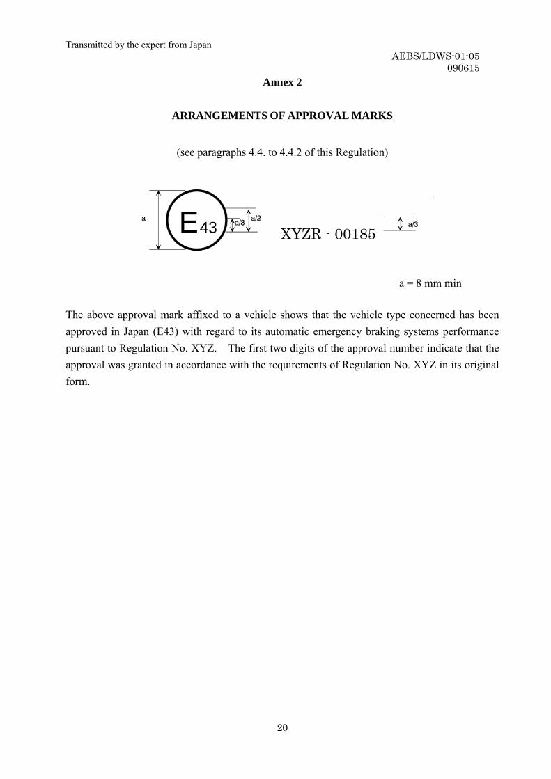
ARRANGEMENTS OF APPROVAL MARKS
(see paragraphs 4.4. to 4.4.2 of this Regulation)
X43 XXR – 00185 XYZR - 00185
a = 8 mm min The above approval mark affixed to a vehicle shows that the vehicle type concerned has been approved in Japan (E43) with regard to its automatic emergency braking systems performance pursuant to Regulation No. XYZ. The first two digits of the approval number indicate that the approval was granted in accordance with the requirements of Regulation No. XYZ in its original form.
Transmitted by the expert from Japan AEBS/LDWS-01-05
090615
21
Annex 3
TEST PROCEDURES FOR STATIONARY OBSTACLE 1. Data processing for the AEBS
The data processing method of deceleration measured by an accelerometer is
prescribed in Annex 6. 2. AEBS functioning test for collision with stationary obstacle 2.1. Road test surface
Tests are conducted on a straight lane with dry, flat, asphalt or concrete-paved
surface. 2.2. Test vehicle condition
The test vehicle shall be laden. A towing vehicle shall be not connected with a
trailer.
2.3. Forward obstacle
This paragraph defines a forward obstacle applicable to a forward obstacle sensor type using a millimeter wave radar. For another type of sensor or multiple types of sensors, different provisions will be defined elsewhere.
The forward obstacle used for the test shall have two reflectors with a radar cross section (RCS) of 15 dBsm or less. */ The forward obstacle shall be set up at the position where the test vehicle collides with it or can be considered to collide with it. The reflector shall be placed in the range which the center point of each reflector is within 1.7m-width in the lateral direction and within 0.09m-height to 1m-height. However, if the height of the forward obstacle sensor of the test vehicle exceeds 1 m, the height of the reflector center point may be raised to the height of the sensor. The reflector may be placed in the near and far positions to the test vehicle in the running direction. In this case, the reflector of the nearest one from the test vehicle shall be set up at the position where the test vehicle
*/ If a radar reflectivity is smaller than two reflectors with a radar cross section (RCS) of 15 dBsm, the test may use the difference forward obstacle.
Transmitted by the expert from Japan AEBS/LDWS-01-05
090615
22
collides with or can be considered to collide with. And construction materials that support the reflector shall be metal covered by radio wave absorption materials or non-metallic materials, so that the AEBS shall not be activated by wave reflection from other than the reflector.
2.4. Test procedures
Initial brake temperature of the test vehicle shall be 100°C or less. The test vehicle shall be driven at the following speeds:
Maximum vehicle speed - 5 km/h (Vmax - 5) ± 2 km/h (shall not exceed 80 km/h in any event),
40 ± 2 km/h, and 20 ± 2 km/h
until it collides with the forward obstacle (or can be considered to collide with it. same here after) or the start of the braking control by the AEBS.
The accelerator shall be kept constant until collision with forward obstacle. The driver shall not operate the brake system at such a timing as affecting the
operation of the AEBS before and after the collision with forward obstacle. The test vehicle speed, deceleration, and the distance to forward obstacle shall be
measured. In addition, the collision warning and emergency event preparation timings shall be checked.
3. Verification test of deactivation of braking control to obstacle outside the test lane
3.1. Road test surface Tests are conducted on a straight lane 3.5 m width with dry, flat, asphalt or
concrete-paved surface.
3.2. Obstacle outside lane
The obstacle outside lane used for the test shall be a vehicle. The obstacle outside lane shall be set up in the same direction as the test vehicle. The side of the obstacle outside lane shall be set up at the symmetric position of outside 0.5m of the lane.
3.3. Test procedures
Transmitted by the expert from Japan AEBS/LDWS-01-05
090615
23
The test vehicle shall be driven at 40 ± 2 km/h speed, keeping its centerline on the lane center, from a point at least 60 m before the obstacles outside lane until the vehicle passes the obstacles. The test shall be repeated three times.
The vehicle speed shall be kept constant. The driver shall not operate the brake system at such a timing as affecting the
operation of the AEBS before and after passing the obstacles outside lane. The test vehicle speed, deceleration, and the distance to obstacles outside lane
shall be measured. In addition, no activation of the AEBS by passing through outside obstacles shall be confirmed.
4. Criteria
4.1. AEBS functioning test for collision with stationary obstacle
The TTC, shall be calculated from the relative speed and the distance to forward obstacle measured in the AEBS functioning test for collision with stationary obstacle, using the next formula.
Distance to forward obstacle (m) x 3.6 TTC (sec) =
Relative speed (km/h)
The average deceleration shall be calculated for an interval after crossing the collision judgment line until the moment of TTC = 0 (sec) calculated above. However, if a braking control based on the collision risk judgment has not been activated in the tests of the relative speed is 40 ± 2 km/h and 20 ± 2 km/h, the phrase "after crossing the collision judgment line" in the above sentence may be replaced by "from a moment 0.3 seconds after crossing the collision judgment line".
4.1.1. A deceleration exceeding 0.98 m/s2 shall be developed when the relative speed is
20 ± 2 km/h. 4.1.2. Within the test condition of an initial speed of braking where the collision
avoidable limit line by steering is lower than the collision avoidable limit line by braking, the average deceleration measured shall be equal to or greater than 3.3 m/s2.
Transmitted by the expert from Japan AEBS/LDWS-01-05
090615
24
4.1.3. The braking control based on collision risk judgment shall start between the collision risk judgment line and the collision judgment line. Above provision does not be applied to a collision warning braking (refer to in paragraphs 2.25.) The start of the braking shall choose (1) or (2) whichever comes earlier. (1) The deceleration is equal to or greater than 2.45m/s2. (2) The braking time of which deceleration exceeds 0.98m/s2 is equal to or greater than 0.8s.
4.1.4. The emergency event preparation shall start at the latest 0.6 seconds before
crossing the collision judgment line. However, if a collision warning has been activating already, the emergency event preparation may be replaced by the collision warning.
4.1.5. The collision warning shall start at the latest 0.8 seconds before the braking
control starts between the collision risk judgment line and the collision judgment line. The start of the braking shall choose (1) or (2) whichever comes first. (1) The deceleration is equal to or greater than 2.45m/s2. (2) The braking time of which deceleration exceeds 0.98m/s2 is equal to or greater than 0.8s.
4.2. AEBS functioning test to obstacle outside the test lane The AEBS shall not activate any braking control, in the specified number of tests.
Above provision does not be applied to a collision warning braking (refer to in paragraphs 2.25.).
5. Curve road
Requirements related to braking control system for damage mitigation of frontal obstacle impact in curved road */
The braking control system for damage mitigation of frontal obstacle impact shall operate normally even in a curved road (example: R380) where a vehicle may run at a high speed.
*/ This paragraph suggests a proposal to be defined in future for the development of brake system for damage mitigation of collision with a forward obstacle, as well as the technology to reduce collision speed by increasing average deceleration. In future, according to the progress of the technology of forward obstacle detection and other technologies, clear test methods will be defined.

Transmitted by the expert from Japan AEBS/LDWS-01-05
090615
25

Transmitted by the expert from Japan AEBS/LDWS-01-05
090615
26
Annex 4
TEST PROCEDURE FOR MOVING OBSTACLE [1. Data processing for the AEBS 2. AEBS functioning test for collision with moving obstacle
… etc ] In the informal meeting, a test procedure for moving obstacle will be discussed to verify the requirements.
Transmitted by the expert from Japan AEBS/LDWS-01-05
090615
27
Annex 5
FUNCTIONING TEST OF THE MALFUNCTION WARNING DEVICE OF AEBS 1. Test procedure
Switch the ignition to OFF position and cause the control unit or the forward
obstacle sensor to be failed: (1) disconnect a connector of the power supply or input or output port of the
control unit, (2) disconnect a connector of the power supply or input or output port of the
forward obstacle sensor. While simulating a malfunction mode by (1) or (2), turn the ignition switch to ON
position and check the malfunction warning signal activation with the test vehicle in stationary.
2. Criteria
The malfunction warning optical signal shall be given within 15 seconds.

Transmitted by the expert from Japan AEBS/LDWS-01-05
090615
28
Annex 6
DATA PROCESSING FOR THE AEBS 1. GENERAL
The frequency range for the vehicle dynamic performance test on the horizontal plane shall be from 0 Hz to a maximum of 2 Hz. By either analogue or digital data processing, requirements in the paragraph 2 or 3 of this annex shall be applied.
2. ANALOGUE DATA PROCESSING
The bandwidth of the entire, combined transducer/recording system shall be no less than the range of 0 Hz to 8 Hz. In order to execute the necessary filtering of signals, low-pass filters shall be employed. The filter cut-off frequency f0
3) shall be greater than 4 Hz, and amplitude errors shall be less than ± 0.5 per cent in the relevant frequency range of 0 Hz to 2 Hz. All analogue signals shall be processed with filters having sufficiently within the required accuracy for time measurement.
Note 1: During analogue filtering of signals with different frequency contents, phase shifts can occur. Therefore, a data processing method, as described in paragraph 3 of this annex, is preferable.
Note 2: As “Filters having sufficiently similar phase characteristics” it is preferable to use filters which have the same type, the same degree, and the same cut-off frequency.
Note 3: The cut-off frequency shall be the frequency for -3 dB gain in the low-pass filters.
3. DIGITAL DATA PROCESSING 3.1 General Consideration Preparation of analogue signals includes considerations of filter amplitude attenuation
and sampling rate in order to avoid aliasing errors, filter phase lags and time delays. Sampling and digitising considerations include pre-sampling amplification of signals to minimize digitising errors; number of bits per one sample; number of samples per one cycle; sample and hold amplifiers; and time-wise spacing of samples. Considerations
Transmitted by the expert from Japan AEBS/LDWS-01-05
090615
29
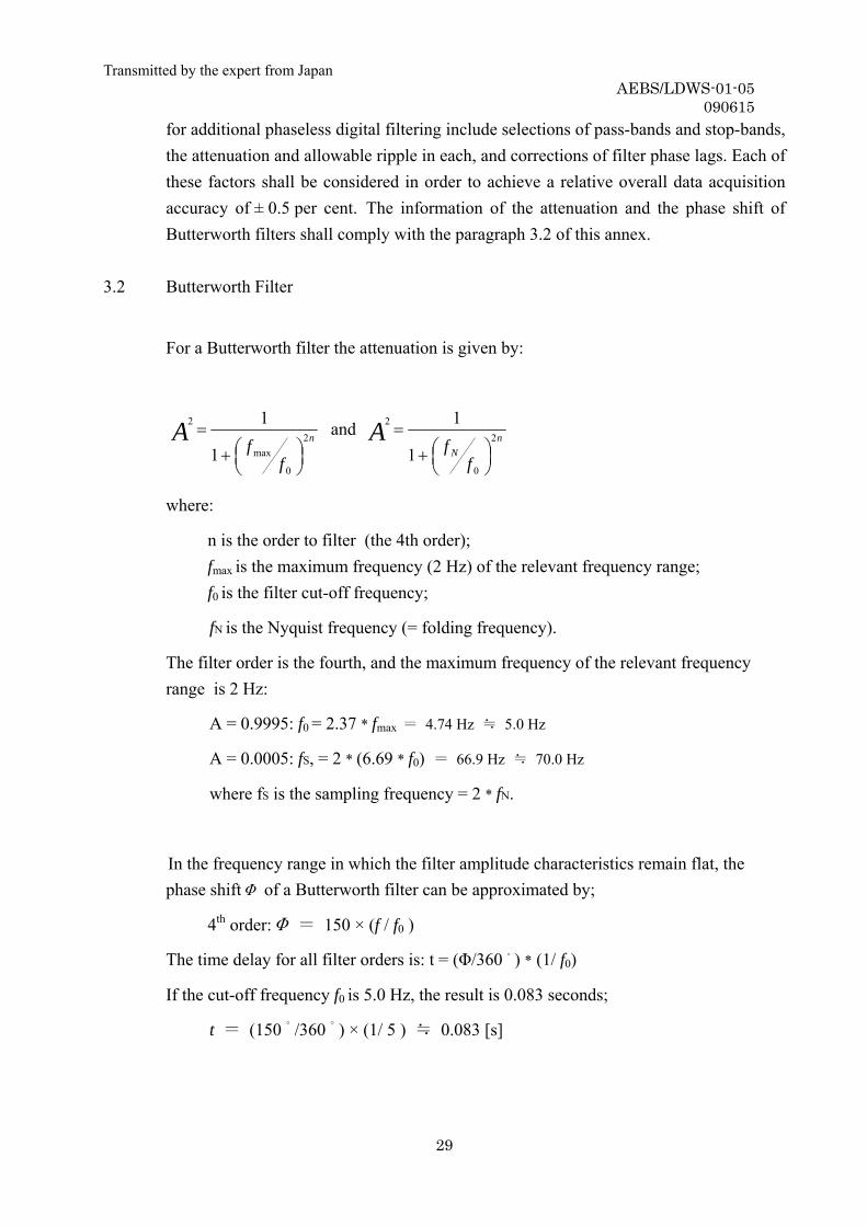
for additional phaseless digital filtering include selections of pass-bands and stop-bands, the attenuation and allowable ripple in each, and corrections of filter phase lags. Each of these factors shall be considered in order to achieve a relative overall data acquisition accuracy of ± 0.5 per cent. The information of the attenuation and the phase shift of Butterworth filters shall comply with the paragraph 3.2 of this annex.
3.2 Butterworth Filter
For a Butterworth filter the attenuation is given by:
n
ffA 2
0
max
2
1
1
⎟⎠⎞⎜
⎝⎛+
= and nN
ffA 2
0
2
1
1
⎟⎠⎞⎜
⎝⎛+
=
where:
n is the order to filter (the 4th order); fmax is the maximum frequency (2 Hz) of the relevant frequency range; f0 is the filter cut-off frequency;
fN is the Nyquist frequency (= folding frequency).
The filter order is the fourth, and the maximum frequency of the relevant frequency range is 2 Hz:
A = 0.9995: f0 = 2.37 * fmax = 4.74 Hz ≒ 5.0 Hz
A = 0.0005: fS, = 2 * (6.69 * f0) = 66.9 Hz ≒ 70.0 Hz
where fS is the sampling frequency = 2 * fN.
In the frequency range in which the filter amplitude characteristics remain flat, the phase shiftΦ of a Butterworth filter can be approximated by;
4th order:Φ = 150 × (f / f0 )
The time delay for all filter orders is: t = (Φ/360 ゚) * (1/ f0)
If the cut-off frequency f0 is 5.0 Hz, the result is 0.083 seconds;
t = (150 ゚/360 ゚) × (1/ 5 ) ≒ 0.083 [s]

Transmitted by the expert from Japan AEBS/LDWS-01-05
090615
30
For the fourth order filters, the cut-off frequency f0 shall be greater than 5.0 Hz (2.37 *
fmax) if phase errors are subsequently adjusted in digital data processing, and shall be greater than 10.0 Hz (5 * fmax) if not. For the fourth order filters, the data sampling frequency fs shall be greater than 70.0 Hz (13.4 * f0).
3.3 Aliasing Errors and Anti-Aliasing Filter In order to avoid uncorrectable aliasing errors, the analogue signals shall be
appropriately filtered before sampling and digitising. The order of the filters to use and their pass-band shall be chosen according to both the required flatness in the relevant frequency range and the sampling rate.
The minimum filter characteristics and sampling rate shall be such that: (a) Within the relevant frequency range of 0 Hz to fmax (2 Hz) the attenuation of
analogue signals shall be at least less than the resolution of the digitising signals. (b) At one-half of the sampling rate (the Nyquist frequency) the amplitude of all
frequency components of signals and noise shall be reduced to less than the system resolution.
For 0.05 per cent resolution the filter attenuation shall be less than 0.05 per cent in 2 Hz
or less, and shall be more than 99.95 per cent at all frequencies which is more than one-half the sampling frequency.
Anti-aliasing filters is recommended to be higher than the fourth order (Ref. 3.2). Filtering shall be required for anti-aliasing, but the excessive analogue filtering shall be avoided. And all filters shall have sufficiently similar phase characteristics to ensure that time delay differences between signals are within the required accuracy for the time measurement.
Note: Phase shifts are especially significant when measured variables are
multiplied together to form new variables, because phase shifts and relative time delays are added while multiplying amplitudes. Phase shifts and time delays can be reduced by making the filter cut-off frequency f0 higher. Whenever equations describing the pre-sampling filters are known, it is practical to remove their phase shifts and time delays by simple algorithms performed in the frequency domain.
Transmitted by the expert from Japan AEBS/LDWS-01-05
090615
31
3.4. Data Sampling and Digitising At 2 Hz the signal amplitude changes by up to 1.2 per cent per one millisecond. To limit
dynamic errors caused by changing analogue inputs to 0.1 per cent, sampling or digitising time shall be less than 32 μs. All pairs or sets of data samples to be compared shall be taken simultaneously or over a sufficiently short time period.
The data system for digitising shall have a resolution of 12 bits (± 0.05 per cent) or more and an accuracy of 2 LSB (± 0.1 per cent). In the process of digitising, amplification of analogue signals before digitising shall be less than 0.2 per cent, which is the total of resolution limitation errors and digitising errors.
3.5 Digital Filtering
For filtering of data sampling by evaluation data, the phaseless (zero phase shifts) digital filters having the following characteristics shall be required.
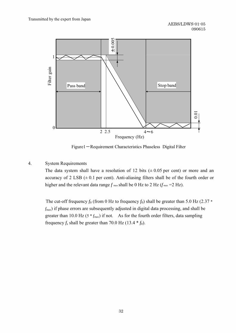
- The pass-band shall be from 0 Hz to 2 Hz. - The stop-band shall start at a range of 4 Hz to 6 Hz. - The filter gain of the pass-band shall be 1±0.005 [(100±0.5) per cent]. - The filter gain of the stop-band shall be ±0.01 (±1 per cent).
Transmitted by the expert from Japan AEBS/LDWS-01-05
090615
32
Figure1-Requirement Characteristics Phaseless Digital Filter
20
1
2.5Frequency (Hz)
±0.
005
0.01
Filte
r gai
n
4~6
Pass band Stop band
4. System Requirements The data system shall have a resolution of 12 bits (± 0.05 per cent) or more and an
accuracy of 2 LSB (± 0.1 per cent). Anti-aliasing filters shall be of the fourth order or higher and the relevant data range f max shall be 0 Hz to 2 Hz (f max =2 Hz).
The cut-off frequency f0 (from 0 Hz to frequency f0) shall be greater than 5.0 Hz (2.37 *
fmax) if phase errors are subsequently adjusted in digital data processing, and shall be greater than 10.0 Hz (5 * fmax) if not. As for the fourth order filters, data sampling frequency fs shall be greater than 70.0 Hz (13.4 * f0).