draft report minnkota milton r young power station
TRANSCRIPT

Geotechnical Environmental and
Water Resources Engineering
DRAFT
Specific Site Assessment for
Coal Combustion Waste
Impoundments at Minnkota
Power Cooperative
Milton R. Young Station Center, North Dakota
Submitted to: U.S. Environmental Protection Agency
Office of Resource Conservation and Recovery 5304P 1200 Pennsylvania Avenue NW Washington, DC 20460
Submitted by: GEI Consultants, Inc.
4601 DTC Boulevard, Suite 900 Denver, CO 80237
December 2010 Project 092884
Ken Hardesty, P.E. Senior Project Engineer

DRAFT
GEI Consultants, Inc. i December 2010 092884 Coal Ash Impoundment SSA Report Minnkota Power Cooperative Milton R. Young Station
Table of Contents
1.0 Introduction 1
1.1 Purpose 1 1.2 Scope of Work 1 1.3 Authorization 2 1.4 Project Personnel 2 1.5 Limitation of Liability 2 1.6 Project Datum 2 1.7 Prior Inspections 2
2.0 Description of Project Facilities 3
2.1 General 3 2.2 Impoundment Dams and Reservoirs 3 2.3 Spillways 5 2.4 Intakes and Outlet Works 5 2.5 Vicinity Map 6 2.6 Plan and Sectional Drawings 6 2.7 Standard Operational Procedures 6
3.0 Summary of Construction History and Operation 7
4.0 Hazard Potential Classification 8
4.1 Overview 8 4.2 Alternate Bottom Ash Pond 8 4.3 Cell 1 and Cell 2 9
5.0 Hydrology and Hydraulics 10
5.1 Floods of Record 10 5.2 Inflow Design Floods 10
5.2.1 Alternate Bottom Ash Pond 10
5.2.2 Cell 1 and Cell 2 11
5.2.3 Determination of the PMF 11 5.2.4 Freeboard Adequacy 11 5.2.5 Dam Break Analysis 11
5.3 Spillway Rating Curves 11 5.4 Evaluation 12
6.0 Geologic and Seismic Considerations 13
7.0 Instrumentation 14
7.1 Location and Type 14
7.2 Readings 14

DRAFT
GEI Consultants, Inc. ii December 2010 092884 Coal Ash Impoundment SSA Report Minnkota Power Cooperative Milton R. Young Station
7.2.1 Flow Rates 14 7.2.2 Staff Gauges 14
7.3 Evaluation 14
8.0 Field Assessment 15
8.1 General 15 8.2 Embankment Dam 15
8.2.1 Dam Crest 15 8.2.2 Upstream Slope 15 8.2.3 Downstream Slope 15
8.3 Seepage and Stability 16
8.4 Appurtenant Structures 16 8.4.1 Outlet Structures 16 8.4.2 Pump Structures 16 8.4.3 Emergency Spillway 16 8.4.4 Water Surface Elevations and Reservoir Discharge 16
9.0 Structural Stability 17
9.1 Visual Observations 17 9.2 Field Investigations 17 9.3 Methods of Analysis 17 9.4 Discussion of Stability Analysis and Results 18 9.5 Seismic Stability and Liquefaction Potential 19
9.6 Summary of Results 20
10.0 Maintenance and Methods of Operation 21
10.1 Procedures 21 10.2 Maintenance of Impoundments 21 10.3 Surveillance 21
11.0 Conclusions 22
11.1 Assessment of Dams 22 11.1.1 Field Assessment 22 11.1.2 Adequacy of Structural Stability 22
11.1.3 Adequacy of Hydrologic/Hydraulic Safety 22 11.1.4 Adequacy of Instrumentation and Monitoring of
Instrumentation 22
11.1.5 Adequacy of Maintenance and Surveillance 23 11.1.6 Adequacy of Project Operations 23
12.0 Recommendations 24
12.1 Corrective Measures and Analyses for the Structures 24 12.2 Corrective Measures Required for Instrumentation and Monitoring
Procedures 24 12.3 Corrective Measures Required for Maintenance and Surveillance
Procedures 24

DRAFT
GEI Consultants, Inc. iii December 2010 092884 Coal Ash Impoundment SSA Report Minnkota Power Cooperative Milton R. Young Station
12.4 Corrective Measures Required for the Methods of Operation of the Project Works 24
12.5 Basis of Assessment 25 12.6 Acknowledgement of Assessment 25
13.0 References 27
List of Tables
Table 2.1: Summary Information for Impoundment Dam Parameters
Table 4.1: Milton R. Young Station – Summary of Impoundment Parameters
Table 9.1: Slope Stability Analyses for Cells 1, 2 and the future Cell 3
Table 9:2: Slope Stability Analyses Results and Guidance Values
List of Figures
Figure 1: Vicinity Map Figure 2: Plan of Ash Impoundments Figure 3: Typical Dam Embankment Sections List of Appendices
Appendix A: Inspection Checklists October 20, 2010 Appendix B: Inspection Photographs October 20, 2010 Appendix C: Reply to Request for Information under Section 104(e) List of Acronyms
CCW coal combustion waste EPA U.S. Environmental Protection Agency FEMA Federal Emergency Management Agency FERC Federal Energy Regulatory Committee GEI GEI Consultants, Inc. HDPE high density polyethylene IDF inflow design flood MW megawatts NDDH North Dakota Department of Health PMF probable maximum flood PMP probable maximum precipitation RCP reinforced concrete pipe USACE U.S. Army Corps of Engineers USBR U.S. Bureau of Reclamation USGS U.S. Geological Survey

DRAFT
GEI Consultants, Inc. 1 December 2010 092884 Coal Ash Impoundment SSA Report Minnkota Power Cooperative Milton R. Young Station
1.0 Introduction
1.1 Purpose
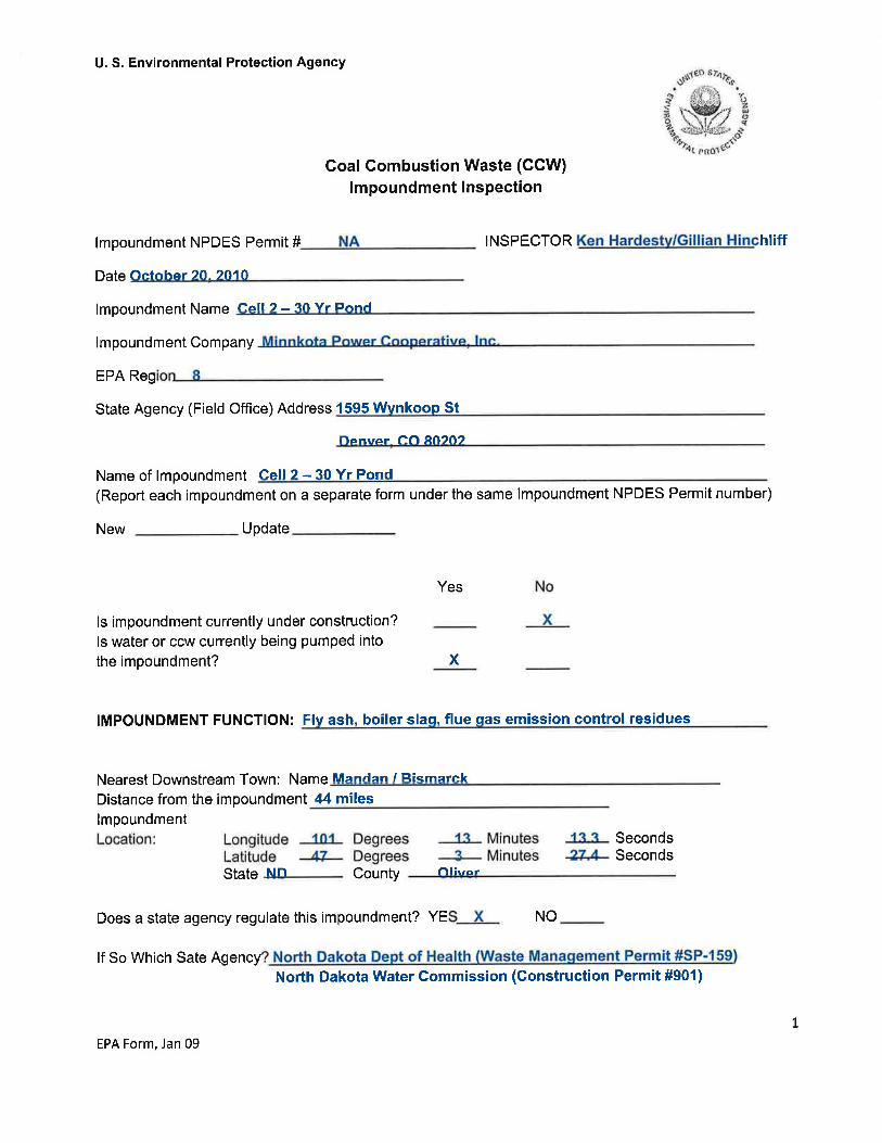
This report presents the results of a specific site assessment of the dam safety of coal combustion waste (CCW) impoundments at the Milton R. Young Station located southeast of Center, North Dakota. The Milton R. Young Station is owned and operated by Minnkota Power Cooperative (Minnkota). The impoundments are Cell 1, Cell 2, and the Alternate Bottom Ash Pond. The specific site assessment was performed on October 20, 2010.
The specific site assessment was performed with reference to Federal Emergency Management Agency (FEMA) guidelines for dam safety, which includes other federal agency guidelines and regulations (such as U.S. Army Corps of Engineers [USACE] and U.S. Bureau of Reclamation [USBR]) for specific issues, and defaults to state requirements were not specifically addressed by federal guidance or if the state requirements were more stringent.
1.2 Scope of Work
The scope of work between GEI Consultants, Inc. (GEI) and the U.S. Environmental Protection Agency (EPA) for the specific site assessment is summarized in the following tasks:
1. Acquire and review existing reports and drawings relating to the safety of the project provided by the EPA and Owners.
2. Conduct detailed physical inspections of the project facilities. Document observed conditions on Field Assessment Check Lists provided by EPA for each management unit being assessed.
3. Review and evaluate stability analyses of the project’s coal combustion waste impoundment structures.
4. Review the appropriateness of the inflow design flood (IDF), and adequacy of ability to store or safely pass the inflow design flood, provision for any spillways, including considering the hazard potential in light of conditions observed during the inspections or to the downstream channel.
5. Review existing dam safety performance monitoring programs and recommend additional monitoring, if required.
6. Review existing geologic assessments for the projects.
7. Submit draft and final reports.

DRAFT
GEI Consultants, Inc. 2 December 2010 092884 Coal Ash Impoundment SSA Report Minnkota Power Cooperative Milton R. Young Station
1.3 Authorization
GEI performed the coal combustion waste impoundment assessment as a contractor to the EPA. This work was authorized by EPA under Contract No. EP09W001698, Order No. EP-B10S-00018 between EPA and GEI, dated September 23, 2010.
1.4 Project Personnel
The scope of work for this task order was completed by the following personnel from GEI:
Ken Hardesty, P.E. Senior Project Engineer/Task Leader Gillian M. Hinchliff Project Engineer Nick Miller, P.E. Project Water Resources Engineer Stephen G. Brown, P.E. Project Manager
The Program Manager for the EPA was Stephen Hoffman.
1.5 Limitation of Liability
This report summarizes the assessment of dam safety of Cell 1, Cell 2, and the Alternate Bottom Ash Pond coal combustion waste impoundments at Milton R. Young Station, Center, North Dakota. The purpose of each assessment is to evaluate the structural integrity of the impoundments and provide summaries and recommendations based on the available information and on engineering judgment. GEI used a professional standard of practice to review, analyze, and apply pertinent data. No warrantees, express or implied, are provided by GEI. Reuse of this report for any other purpose, in part or in whole, is at the sole risk of the user.
1.6 Project Datum
Horizontal datum on the drawings is based on survey control provided by KBM, Inc. Topography is based on photogrammetic methods from aerial photographs taken on September 27, 1983, July 29, 1991, and September 24, 2004. The project vertical datum is unknown.
1.7 Prior Inspections
Cell 1 and Cell 2 are permitted by the North Dakota Department of Health (NDDH) – Division of Waste Management, and are typically inspected by the Division of Waste Management at least once per year. Inspection reports from 2004 through 2007 were provided to us for our review. The inspection reports are mostly for environmental purposes and do not appear to address dam safety concerns. The Alternate Bottom Ash Pond is permitted by the NDDH – Division of Water Quality, and is typically inspected by the Division of Water Quality at least once per year. Inspection reports were not provided for the Alternate Bottom Ash Pond.

DRAFT
GEI Consultants, Inc. 3 December 2010 092884 Coal Ash Impoundment SSA Report Minnkota Power Cooperative Milton R. Young Station
2.0 Description of Project Facilities
2.1 General
Milton R. Young Station is a coal-fired power plant consisting of two units that generate about 700 megawatts (MW) combined. Unit 1 is owned and operated by Minnkota and went online in 1970. Unit 2 is owned by Square Butte Electric Cooperative and operated by Minnkota. Unit 2 went online in 1977. The power plant is located approximately 5 miles southeast of Center in Oliver County, North Dakota (see Figure 1). The Cell 1 and Cell 2 impoundments are located adjacent to and south of the plant, and the Alternate Bottom Ash Pond impoundment is located adjacent to and west of the plant. The CCW impoundments include Cell 1, Cell 2, and the Alternate Bottom Ash Pond (see Figure 2).
2.2 Impoundment Dams and Reservoirs
The embankment dams of the three CCW impoundments have not been previously assigned a hazard potential by a state or federal agency. Based on the geometry of the impoundments and the facilities downstream, recommended hazard potential classifications for the impoundments have been developed in Section 4.0 of this report. The basic dimensions and geometry of the CCW impoundments are summarized in Table 2.1.
The Alternate Bottom Ash Pond was commissioned in 1986 and covers approximately 2.4 acres with a storage capacity of 87 acre-feet. The Alternate Bottom Ash Pond temporarily holds sluiced bottom ash when Units 1 and 2 are in outage. The Alternate Bottom Ash Pond is used for approximately 2 to 3 months every 3 years. During our site visit on October 20, 2010, the plant was in outage and the Alternate Bottom Ash Pond was being used.
Cell 1, Cell 2 and the future Cell 3 (currently under construction) are permitted under the same NDDH permit. The design and construction for Cells 1, 2 and 3 are similar and combine a deep excavated pit with a perimeter embankment dike. The ponds are excavated to a depth of about 50 feet to expose the Hagel coal formation. The coal formation is approximately 8 to 10 feet thick. When the formation is exposed, the coal is mined, and the pond construction continues. Each pond is designed for a 10 year life span at the end of which the pond is full of ash. The full pond is dewatered and capped as a dry landfill. Water is returned to the plant for reuse in the scrubber system.
Cell 1 was commissioned in 1997, and Cell 2 was commissioned in 2005 and expanded in accordance with design plans in 2007 and 2008. Cell 1 is currently being dewatered into Cell 2, and interior grades are being raised to final design grades for capping.

DRAFT
GEI Consultants, Inc. 4 December 2010 092884 Coal Ash Impoundment SSA Report Minnkota Power Cooperative Milton R. Young Station
Cell 1 and Cell 2 store fly ash, boiler slag, and flue gas emission control residuals. The Alternate Bottom Ash Pond temporarily stores bottom ash, which is then dewatered and hauled to a landfill.
The embankments of the ponds were constructed from on-site, native soils consisting of sands, silts and clays. The interior slopes of Cell 1 and Cell 2 have a 4-foot thick clay liner covered with a 5-foot thick random clay layer, geotextile for erosion control and a layer of bottom ash. The Alternate Bottom Ash Pond has a minimum 15-foot thick clay liner covered with a bottom ash/concrete mix liner for erosion control. The dam embankments have crests varying from 15 to 75 feet wide and side slopes varying from 2H:1V to 4.5H:1V.
Table 2.1: Summary Information for Impoundment Dam Parameters
Parameter Value
Dam Alternate Bottom Ash Pond Cell 1 Cell 2
Estimated Maximum Height (ft) 311 ~1003 ~903
Estimated Perimeter Length (ft) 1,600 4,8305 4,760 Crest Width (ft) ~15 40-75 17.25-75 Lowest Crest Elevation (ft) 1960 2100 2086 Design Side Slopes Upstream/Downstream (H:V) 2:1/2:1 2.5:1/4.5:1 2.5:1/2.5-4.5:16
Estimated Freeboard (ft) at time of site visit 9.52 04 14.5 Storage Capacity (ac-ft)
87 1,1783 1,252
Surface Area (acres) 2.4 305 27
1. Maximum Height of the Alternate Bottom Ash Pond was estimated from the approximate bottom elevation of the Cooling Water Canal. The Cooling Water Canal water level elevation is approximately El. 1934.9, and plant personnel indicated the canal is approximately 6 feet deep.
2. Pond water level elevation and freeboard estimated based on observed conditions and design drawings. 3. Maximum heights of Cell 1 and Cell 2 and storage capacity of Cell 1 were estimated from a maximum crest
El. 2100 and the profiles of existing ground shown on design drawing G5 and G6 prepared by Barr Engineering Co., dated February 1994.
4. Cell 1 is currently being filled with dry ash hauled to the pond to raise grades for final cover. A capping plan has been approved for Cell 1. Any water in the pond is maintained with two feet of freeboard.
5. Surface area and perimeter length are estimated from aerial photographs. 6. Downstream slopes are 4.5:1 except for the south side where Cell 3 is currently being constructed. On the
south embankment, downstream slopes are approximately 2.5:1.
In approximately 1979 to 1980, the Butterfly Pond was commissioned to hold ash sluiced from the plant. The Butterfly Pond is located directly north of Cell 1 and consists of two 4 acre sections, the west section and east section, separated by a divider dike. The Butterfly Pond was last used as a pond in 1997, when Cell 1 was commissioned. The Butterfly Pond is currently certified to hold solid waste, but is not certified as a pond. Precipitation from the Butterfly Pond is pumped to Cell 2. The Butterfly Pond is not assessed in this report because it has not received sluiced ash since 1997 and is not certified to function as a pond.

DRAFT
GEI Consultants, Inc. 5 December 2010 092884 Coal Ash Impoundment SSA Report Minnkota Power Cooperative Milton R. Young Station
The Horseshoe Pit Evaporation Pond was commissioned in 1990 and is located approximately 3 miles northwest of the plant. The Horseshoe Pit Evaporation Pond receives leachate from the adjacent Horseshoe Landfill, which is a capped and closed landfill containing CCW. The Horseshoe Pit Evaporation Pond and adjacent landfill are permitted by the NDDH Division of Waste Management. The Horseshoe Pit Evaporation Pond is not assessed in this report because it does not receive sluiced ash or other CCW.
2.3 Spillways
The three CCW impoundments (the Alternate Bottom Ash Pond, Cell 1 and Cell 2) do not have uncontrolled emergency spillways.
2.4 Intakes and Outlet Works
The Alternate Bottom Ash Pond has two permanent inlet pipes and two temporary inlet pipes, which do not penetrate the dike. The permanent inlet pipes are above-ground pipes supported on concrete piers. The temporary inlet pipes are laid directly on the ground surface over the dike crest. The outlet consists of a square concrete drop-inlet structure with stop logs that discharges through an 18-inch-diameter reinforced concrete pipe (RCP) to the Cooling Water Canal located at the toe of the north dike. The Cooling Water Canal discharges into Nelson Lake.
Cell 1 leachate is discharged through two 18-inch-diameter PVC pipes at about invert El. 2005 that discharge to Cell 2. The pipes are encased in concrete along the upstream slope of the south embankment and do not penetrate the dike. Precipitation that accumulates in Cell 1 is pumped to Cell 2 through temporary pipes that are placed over the dike crest.
Two inlet pipes from Unit 1 to Cell 2 are routed across Cell 1 and over Cell 2’s north embankment, and two pipes from Unit 2 are routed across Cell 1, along the crest of Cell 2’s west embankment and into the pond. The inlet pipes do not penetrate the embankments. Water from Cell 2 is decanted through four 14-inch-diameter high density polyethylene (HDPE) siphon pipes and flows by gravity back to the plant for reuse in the scrubber system. Two pipes go to Unit 1 and two pipes go to Unit 2. The intake invert of the pipes is currently set at about El. 2071.5. The siphon outlet pipes are placed above the 4-foot thick clay liner and beneath the 5-foot thick random clay fill on the dike crest. Currently, the pipes penetrate the dike at about El. 2081, and the water level is maintained by Minnkota below El. 2079. The siphons can lift up to about 15 feet of head, and as water levels in Cell 2 rise, the elevation of the pipes are raised and the clay liners are rebuilt. Cell 2 also has two 18-inch-diameter PVC pipes at about invert El. 2008 that are encased in concrete along the upstream slope of the south embankment and will be used to dewater leachate from Cell 2 after Cell 2 is filled and capped.

DRAFT
GEI Consultants, Inc. 6 December 2010 092884 Coal Ash Impoundment SSA Report Minnkota Power Cooperative Milton R. Young Station
2.5 Vicinity Map
Milton R. Young Station is located approximately 5 miles southeast of Center in Oliver County, North Dakota, as shown on Figure 1. The Cell 1 and Cell 2 impoundments are located adjacent to and south of the plant, and the Alternate Bottom Ash Pond impoundment is located adjacent to and west of the plant.
2.6 Plan and Sectional Drawings
Engineering design drawings for the Alternate Bottom Ash Pond were prepared by Ebasco Services Inc. Design and Construction drawings for Cell 1 and Cell 2 were prepared by Barr Engineering Co.
2.7 Standard Operational Procedures
Milton R. Young Station is a coal-fired power plant composed of two units. Unit 1 produces about 250 MW and Unit 2 produces about 450 MW for a total combined capacity of about 700 MW. Coal is mined and transported from the nearby BNI Coal mine, where it is then combusted to power the steam turbines. The burning of coal produces several gases and fly ash which are vented from the boiler, and bottom ash, which is made of coarse fragments, falls to the bottom of the boiler, and is removed along with boiler slag. Coal combustion waste from Units 1 and 2 are wet sluiced into Cell 2. When Units 1 and 2 are in outage, bottom ash is wet sluiced into the Alternate Bottom Ash Pond.
Cells 1 and 2 are used for primary settling and permanent storage of CCW. Wet ash is no longer sluiced to Cell 1, and Cell 1 is being prepared for capping. Stormwater and leachate from Cell 1 are discharged into Cell 2. Water from Cell 2 is discharged back to the power plant for reuse in the scrubber facility.
The Alternate Bottom Ash Pond is used for primary settling on a temporary basis. The bottom ash settles out and the water is discharged to the Cooling Water Canal which discharges to Nelson Lake. The Alternate Bottom Ash Pond is only used during plant outages for approximately 2 to 3 months every 3 years. After the water is discharged to the Cooling Water Canal, the dry bottom ash in the pond is hauled to a landfill.

DRAFT
GEI Consultants, Inc. 7 December 2010 092884 Coal Ash Impoundment SSA Report Minnkota Power Cooperative Milton R. Young Station
3.0 Summary of Construction History and Operation
The first unit at Milton R. Young Station went online in 1970. The second unit went online in 1977. The Butterfly Pond was commissioned sometime in 1979 or 1980, and stopped receiving sluiced ash in 1997 when Cell 1 was commissioned.
The Alternate Bottom Ash Pond was commissioned in 1986. The dikes of the Alternate Bottom Ash Pond were constructed of on-site soils. On-site soils consist of sands, silts and clays. The pond has an approximate 15-foot thick clay liner covered with a bottom ash/concrete mix liner for erosion control.
Cell 1 was commissioned in 1997, and Cell 2 was commissioned in 2005. Cells 1 and 2 were excavated to a depth of about 50 feet to mine coal from the Hagel formation. Embankments were constructed of excavated on-site soils reused as fill. Cells 1 and 2 have a 4-foot thick clay liner covered with 5 feet of random clay fill, a geotextile for erosion control and a layer of bottom ash. Typical geometries of the dikes are presented in Table 2.1 and Figure 3.
An original design drawing for the Alternate Bottom Ash Pond was available along with operating procedures for the pond. Design reports and construction records were not available for the Alternate Bottom Ash Pond. Design and construction drawings and records were available for Cells 1 and 2. Records indicate CCW was not present in the foundation materials for any of the ponds. Construction documentation for Cells 1 and 2 reports topsoil and subsoil were stripped within the dike footprints, and fill material was placed in lifts and compacted. Compaction records were available for our review. When embankments for Cells 1 and 2 were raised, the embankments were raised on the downstream slope and were not founded on CCW. The clay liner was removed from the top of the dike during the dam raise and reconstructed on the upstream slope to provide a continuous 4-foot thick clay liner as the dike was raised.
No evidence of prior releases, failures or patchwork construction was observed during the site visit or disclosed by plant personnel. The ponds were constructed on natural soils.

DRAFT
GEI Consultants, Inc. 8 December 2010 092884 Coal Ash Impoundment SSA Report Minnkota Power Cooperative Milton R. Young Station
4.0 Hazard Potential Classification
4.1 Overview
According to the Federal Guidelines for Dam Safety the hazard potential classification for the CCW impoundments is based on the possible adverse incremental consequences that result from release of stored contents due to failure of the dam or misoperation of the dam or appurtenances. Impoundments are classified as Low, Significant, or High hazard, depending on the potential for loss of human life and/or economic and environmental damages.
4.2 Alternate Bottom Ash Pond
The Alternate Bottom Ash Pond dikes with a surface area of about 2.4 acres and a height of about 31 feet would be considered a “small” sized dam in accordance with the USACE Recommended Guidelines for Safety Inspection of Dams ER 1110-2-106 criteria.
A hydraulics and hydrology study and dam break analysis has not been performed for the Alternate Bottom Ash Pond. However, based on inspection a failure of the north or west dike of the Alternate Bottom Ash Pond would result in CCW being released in the Cooling Water Canal and Nelson Lake. Minnkota constructed Nelson Lake in the 1960’s to provide water for the plant, and Minnkota owns the lake and surrounding land. Minnkota Power allows Nelson Lake to be used by the general public for recreational purposes. The Alternate Bottom Ash Pond volume is small relative to Nelson Lake, and therefore, impacts of an accidental release of CCW into Nelson Lake would be limited to environmental impacts. A release into Nelson Lake is not anticipated to cause loss of life, and environmental losses are expected to be limited to Minnkota property. A failure of the south dike would release CCW onto Minnkota plant roads and surrounding property, and is not expected to cause loss of life. A failure of the east embankment would release CCW into the North Retaining Basin. The North Retaining Basin receives rainfall runoff and low volume sump water from coal handling facilities. During the site visit, very little water was observed in the North Retaining Basin, and the basin is expected to be able to hold the inflow from the Alternate Bottom Ash Pond in the event of a failure of the east dike.
Consistent with the Federal Guidelines for Dam Safety and the North Dakota State Water Commission, Department of Dam Safety, North Dakota Dam Design Handbook, we recommend the Alternate Bottom Ash Pond be classified as a "Low" hazard structure.

DRAFT
GEI Consultants, Inc. 9 December 2010 092884 Coal Ash Impoundment SSA Report Minnkota Power Cooperative Milton R. Young Station
4.3 Cell 1 and Cell 2
The pond size and capacity of each unit provided by Minnkota is summarized in Table 4.1. The dam height is estimated based on available design drawings and topographic information.
Table 4.1: Milton R. Young Station – Summary of Impoundment Parameters
Pond Name Height
(ft) Storage (Ac-ft)
Surface Area (acres)
Cell 1 ~100 1,178 30
Cell 2 ~90 1,252 27
Based on current pond heights and storage capacity shown in Table 4.1 the size classification for Cell 1 and Cell 2 is “Intermediate” in accordance with the USACE Recommended Guidelines for Safety Inspection of Dams ER 1110-2-106 criteria.
A hydraulics and hydrology study and dam break analysis has not been performed for Cell 1 or Cell 2. However, based on inspection a failure of the north or east dikes of Cell 1 or Cell 2 would result in CCW being released towards the plant and Nelson Lake Dam. The diversion ditch on the east side of the impoundments is expected to be overwhelmed and it is possible CCW could flow along natural drainage paths to the downstream slope of Nelson Lake Dam and enter Square Butte Creek. The closest structure downstream of Nelson Lake Dam is approximately 6 miles. Erosion of the downstream slope of Nelson Lake Dam could potentially occur. Loss of life is not anticipated, but environmental losses from CCW material entering Square Butte Creek could occur. A failure of the west dike of Cells 1 or 2 would release CCW to reclaimed agricultural fields owned by Minnkota located west of the ponds. Due to current construction of Cell 3, a release of the south dike of Cell 2 would result in CCW floodwaters flowing to the south and then east and/or west. A breach of the south dike is expected to be relatively slow, and it is anticipated that construction personnel would have time to vacate the area in the event of a breach. Loss of life is not anticipated.
Based on potential environmental impacts to Square Butte Creek and associated economic impacts, and consistent with the Federal Guidelines for Dam Safety and the North Dakota State Water Commission, Department of Dam Safety, North Dakota Dam Design Handbook, we recommend Cell 1 and Cell 2 be classified as "Significant" or “Medium” hazard structures.

DRAFT
GEI Consultants, Inc. 10 December 2010 092884 Coal Ash Impoundment SSA Report Minnkota Power Cooperative Milton R. Young Station
5.0 Hydrology and Hydraulics
5.1 Floods of Record
Floods of record have not been evaluated and documented for the CCW impoundments at the Milton R. Young Station.
5.2 Inflow Design Floods
Currently there is no hazard classification for the three CCW impoundments at the Milton R. Young Station. We recommend the Alternate Bottom Ash Pond be rated “Low” hazard (Section 4). Based on the recommended “Low” hazard classification, the North Dakota Dam Design Handbook specifies “Low” hazard dams between 25 to 39 feet high be capable of passing the 30 percent probable maximum precipitation (PMP) without overtopping the dam. The USACE Recommended Guidelines for Safety Inspection of Dams ER 1110-2-106 recommends a small “Low” hazard dam be capable of passing the 50- to 100-year storm event without overtopping the dam. Considering the relatively low economic and environmental damages that could potentially occur upon failure, and the recommended range of inflow design storms, it is reasonable to select the 6-hour 30 percent PMP storm event as the inflow design storm. The 6-hour 30 percent PMP precipitation event at the Milton R. Young Station is about 6.5 inches based on Hydrometeorological Report Number 51 6-hour PMP data.
Based on observations during the field inspection, we recommend Cell 1 and Cell 2 be rated a “Significant” hazard dam (see Section 4). Based on the recommended “Significant” hazard classification, the North Dakota Dam Design Handbook specifies “Significant” or “Medium” hazard dams over 55 feet high be capable of passing the 50 percent probable maximum precipitation (PMP) without overtopping the dam. The USACE Recommended Guidelines for Safety Inspection of Dams ER 1110-2-106 recommends an intermediate “Significant” hazard dam be capable of passing 50 to 100 percent of the probable maximum flood (PMF) without overtopping the dam. Considering the “Significant” hazard rating, the scale of the economic and environmental damages that could potentially occur upon failure, and the recommended range of inflow design storms, it is reasonable to select 50 percent of the PMP as the inflow design storm for Cell 1 and Cell 2. The 6-hour 50 percent PMP precipitation at the Milton R. Young Station is about 10.8 inches based on Hydrometeorological Report Number 51 6-hour PMP data.
5.2.1 Alternate Bottom Ash Pond
The Alternate Bottom Ash Pond is a diked pond that has contributing drainage area limited to the impoundment. The Alternate Bottom Ash Pond is normally empty except for

DRAFT
GEI Consultants, Inc. 11 December 2010 092884 Coal Ash Impoundment SSA Report Minnkota Power Cooperative Milton R. Young Station
approximately 3 months every 3 years when the plant is in outage. When the Alternate Bottom Ash Pond is in use, the maximum operating water level is approximately El. 1957.3, which provides about 2.7 feet of freeboard. Based on the 6-hour 30 percent PMP, the Alternate Bottom Ash Pond would have a water surface elevation of about El. 1957.8, providing 2.2 feet of freeboard. Based on these results, the Alternate Bottom Ash Pond meets the regulatory requirements for storage of the 6-hour 30 percent PMP inflow design flood without overtopping the dam.
5.2.2 Cell 1 and Cell 2
The contributing drainage areas for Cell 1 and Cell 2 are limited to the impoundments because of their perimeter dikes. Cell 1 is not currently receiving sluiced ash and grades are being raised to design cover grades with dry, hauled ash. At the time of the site visit, there was a limited amount of water observed in Cell 1. Any water in Cell 1 was maintained with a minimum of 2 feet of freeboard. It appears from topographic drawings dated June 2, 2010, that on average there is greater than one foot of freeboard available for Cell 1, which is greater than the 10.8 inches that needs to be stored. Therefore, in the event of the 50 percent PMP, Cell 1 would be able to store the design flood without overtopping the dam.
Cell 2 had a water level elevation of about El. 2071.5 at the time of the site inspection, which provides about 14.5 feet of freeboard from the lowest dike elevation. Minnkota personnel indicated to GEI at the site visit, that at least 2 feet of freeboard is maintained in the pond at all time. In the event of the 50 percent PMP, Cell 2 would be able to store the design flood without overtopping the dam.
5.2.3 Determination of the PMF
Not applicable.
5.2.4 Freeboard Adequacy
Based on a simplified evaluation, the freeboard appears to be adequate to store the inflow design flood at the three CCW impoundments.
5.2.5 Dam Break Analysis
Dam break analyses have not been performed for the three CCW impoundments at the Milton R. Young Station.
5.3 Spillway Rating Curves
The three CCW impoundments do not have emergency spillways.

DRAFT
GEI Consultants, Inc. 12 December 2010 092884 Coal Ash Impoundment SSA Report Minnkota Power Cooperative Milton R. Young Station
5.4 Evaluation
Based on the current facility operations and inflow design floods documents, the Alternate Bottom Ash Pond, Cell 1 and Cell 2 at the Milton R. Young Station appear to have adequate capacity to store the regulatory design floods without overtopping the dams. A dam break analysis has not been performed for Cell 1 and Cell 2 to determine if a dam break flood would cause significant erosion damage to Nelson Lake Dam.

DRAFT
GEI Consultants, Inc. 13 December 2010 092884 Coal Ash Impoundment SSA Report Minnkota Power Cooperative Milton R. Young Station
6.0 Geologic and Seismic Considerations
Boring logs and construction laboratory test results indicate the overburden soil consists of brown to gray clay, silt, and silty to clayey sands. The Hagel lignite coal formation is located approximately 50 feet below ground surface in the area of Cell 1 and Cell 2. Bedrock in the area consists of layered claystone, siltstone and sandstone.
We are not aware of any seismic analyses that have been performed on the dams at Milton R. Young Station. According to the 2008 U.S. Geological Survey (USGS) Seismic Hazard Map of North Dakota, the site has a regional probabilistic peak ground acceleration of approximately 0.03g with a 2 percent Probability of Exceedance within 50 years (recurrence interval of approximately 2,500 years). This level of seismic acceleration is considered very low.

DRAFT
GEI Consultants, Inc. 14 December 2010 092884 Coal Ash Impoundment SSA Report Minnkota Power Cooperative Milton R. Young Station
7.0 Instrumentation
7.1 Location and Type
There are no instruments installed at the CCW impoundments. According to the project drawings, there are monitoring wells along the Cell 1 east embankment and the divider dike between Cell 1 and Cell 2; however, the monitoring wells are for environmental purposes and readings are not analyzed with respect to dam safety.
7.2 Readings
7.2.1 Flow Rates
Flow rates are not recorded at the CCW impoundment.
7.2.2 Staff Gauges
There are no staff gauges at the CCW impoundment.
7.3 Evaluation
There are no instruments installed at the CCW impoundments. It would be beneficial to install staff gauges and flow measurement devices to measure and record water levels in the ash ponds and flows into and out of the ash ponds, and surveyed benchmarks and embankment settlement monuments to measure and record movement of the dikes and to tie measurements to a known vertical datum. Monitoring well readings should be recorded and analyzed with respect to dam safety.

DRAFT
GEI Consultants, Inc. 15 December 2010 092884 Coal Ash Impoundment SSA Report Minnkota Power Cooperative Milton R. Young Station
8.0 Field Assessment
8.1 General
A site visit to assess the condition of the CCW impoundments at the Milton R. Young Station was performed on October 20, 2010, by Ken Hardesty, P.E., and Gillian M. Hinchliff of GEI. Craig Bleth and Scott Hopfauf from Minnkota, Diana Trussell and Ted Poppke from the North Dakota Department of Health – Division of Waste Management, and Karen Goff and Jeff Berger from the North Dakota State Water Commission assisted in the assessment.
The weather during the site visit (October 20, 2010) was generally sunny, with temperatures around 60 degrees Fahrenheit. The ground was dry at the time of the site visit.
At the time of inspection, GEI completed an EPA inspection checklist, which is provided in Appendix A, and photographs, which are provided in Appendix B. Field assessment of the three CCW impoundments included a site walk to observe the dam crest, upstream slope, downstream slope, and intake structures.
8.2 Embankment Dam
8.2.1 Dam Crest
The dam crests of the three CCW impoundments appeared to be in good condition. No signs of cracking, settlement, movement, erosion or deterioration were observed during the assessment. The dam crest surface is generally composed of road base material that traverses the length of the dam for vehicle access.
8.2.2 Upstream Slope
The upstream slopes of the three CCW impoundments are protected by clay liners and erosion control measures such as a geotextile and bottom ash layer for Cells 1 and 2 and a bottom ash/concrete mix for the Alternate Bottom Ash Pond. The upstream slope protection for the three CCW impoundments showed signs of minor erosion, generally in the layer of bottom ash or bottom ash/concrete mix. The slope protection otherwise appeared to be in satisfactory condition. No scarps, sloughs, depressions or other indications of slope instability were observed during the inspection of the three CCW impoundments.
8.2.3 Downstream Slope
The downstream slopes of the three CCW impoundments have well-established stands of grass, which provides some erosion protection. No scarps, sloughs, depressions or other indications of slope instability were observed during the inspection of the ponds. An erosion

DRAFT
GEI Consultants, Inc. 16 December 2010 092884 Coal Ash Impoundment SSA Report Minnkota Power Cooperative Milton R. Young Station
channel was observed near the west embankment downstream toe of Cell 1. The channel appears to have eroded due to surface runoff (see Photo 30) and is not significant enough at this time to impact Cell 1.
8.3 Seepage and Stability
No evidence of seepage was observed at the three CCW impoundments. No evidence of slumps, sloughs, or settlement associated with slope instability was observed.
8.4 Appurtenant Structures
8.4.1 Outlet Structures
The concrete outlet structure at the Alternate Bottom Ash Pond appeared to be in good condition consistent with its age. The structure was observed to be working properly and was discharging decant water to the Cooling Water Canal. The outlet conduits for Cell 2 appeared to be in good condition. The Cell 2 outlet conduits were not conveying water at the time of the site visit due to the plant outage. The outlet conduits for Cell 1 appeared to be in good condition.
8.4.2 Pump Structures
No pump structures are present at the three CCW impoundments.
8.4.3 Emergency Spillway
The three CCW impoundments do not have emergency spillways.
8.4.4 Water Surface Elevations and Reservoir Discharge
The water surface elevation in the Alternate Bottom Ash Pond was estimated by GEI to be about El. 1950.5. Cell 1 is not currently receiving sluiced ash, and interior grades are being raised for capping with dry, hauled ash. Minnkota personnel indicated that any water in Cell 1 was maintained with a minimum of two feet of freeboard. Minnkota indicated the water surface elevation for Cell 2 at the time of inspection was approximately El. 2071.5.

DRAFT
GEI Consultants, Inc. 17 December 2010 092884 Coal Ash Impoundment SSA Report Minnkota Power Cooperative Milton R. Young Station
9.0 Structural Stability
9.1 Visual Observations
The assessment team saw no visible signs of instability associated with the dikes of the three CCW impoundments during the October 20, 2010 site assessment.
9.2 Field Investigations
No subsurface investigation reports were provided for the Alternate Bottom Ash Pond. Based on the design and construction drawings, the following subsurface investigations were performed at the site:
Multiple boring and test pit exploration programs were performed for Cells 1, 2 and 3 by Barr Engineering Co. Based on the drawing “Existing Conditions” dated 8/30/2003, prepared by Barr Engineering Co. exploration programs appear to have been performed in 1991, 1992, and 2000. Based on the drawing “Existing Conditions & Monitoring System” dated February 1994, prepared by Barr Engineering Co. explorations were also performed in 1994. The plans provided to GEI may not have all of the explorations performed to date for Cells 1, 2 and 3.
According to the plans, three monitoring wells were installed on the Cell 1 east dike. Two monitoring wells were installed on the Cell 1 south dike (divider dike between Cell 1 and Cell 2). It appears about 15 borings were performed for Cell 1 based on the plans provided.
Approximately 16 borings and four test pits were performed for Cell 2.
About seven borings were performed for the future Cell 3. Additionally, four monitoring wells were installed within the limits of the future Cell 3.
9.3 Methods of Analysis
Slope stability analyses have not been performed for the Alternate Bottom Ash Pond. In 1994, Barr Engineering Co. performed slope stability analyses for a representative section of Cells 1 and 2 and the future Cell 3 using the computer program SLOPE/W by GeoStudio. The slope stability analysis was performed as part of the initial design of the CCW impoundment embankments and was included as part of the NDDH permit application. Slope stability analyses performed are summarized in Table 9.1.

DRAFT
GEI Consultants, Inc. 18 December 2010 092884 Coal Ash Impoundment SSA Report Minnkota Power Cooperative Milton R. Young Station
Table 9.1: Slope Stability Analyses for Cells 1, 2 and the future Cell 3
Slope Loading Condition
Upstream Slope
Rapid Liner Construction Liner Construction
Facility Operations – Early Stages Facility Operations – Late Stages Liner Failure – Rapid Drawdown
Deep Rotational Failure – Rapid Drawdown
Downstream Slope Maximum Pool – Average Soil Properties Maximum Pool – Minimum Soil Properties
Maximum Pool – Minimum Soil Properties, Failure along Coal Bed
The upstream slope stability analyses were modeled with a height of 30 feet, a slope angle of 2.5H:1V, and a 4-foot thick liner. The clay liner undrained and drained strength parameters were determined from laboratory testing. The clay liner undrained strength parameters were modeled with a unit weight of 115 pound per cubic foot (pcf), friction angle of 19.4 degrees, and cohesion of 0.05 tons per square foot (tsf). Drained strength was modeled with a unit weight of 94 pcf, friction angle of 23.9 degrees, and cohesion of 0.16 tsf.
The downstream slope stability analyses were modeled with both average and minimum soil properties as determined from laboratory testing. The average strength parameters were modeled with a unit weight of 127 pcf, friction angle of 31.6 degrees and no cohesion. Minimum embankment soil properties were modeled with a unit weight of 127 pcf, a friction angle of 27 degrees, and no cohesion. The downstream slope configuration included a height of about 95 feet and downstream slope of 3H:1V. A phreatic surface was included in case of failure of the clay liner. The phreatic surface was modeled as maximum pool elevation on the upstream slope to the downstream toe. The phreatic surface was modeled with substantial head loss through the embankment.
9.4 Discussion of Stability Analysis and Results
The material properties used in the Barr Engineering Co. stability evaluations for the Cell 1, 2 and 3 representative slope stability section are considered consistent with drained and undrained parameters. The minimum factors of safety for each load case are shown in Table 9.2.

DRAFT
GEI Consultants, Inc. 19 December 2010 092884 Coal Ash Impoundment SSA Report Minnkota Power Cooperative Milton R. Young Station
Table 9:2: Slope Stability Analyses Results and Guidance Values
Slope Loading Condition
Calculated Factor of
Safety
Minimum Recommended Factor of Safety
(FERC)
Upstream Slope
Rapid Liner Construction 1.6 1.3 Liner Construction 3.3 1.3
Facility Operations – Early Stages 3.1 – 6.4 1.3
Facility Operations – Late Stages 2.6 1.5 Liner Failure – Rapid Drawdown 0.7 1.1 Deep Rotational Failure – Rapid
Drawdown 1.4 1.1
Downstream Slope
Maximum Pool – Average Soil Properties 1.83 - 1.97 1.5 Maximum Pool – Minimum Soil Properties 1.51 - 1.63 1.5
Maximum Pool – Minimum Soil Properties, Failure along Coal Bed 1.88 - 2.30 1.5
The calculated factors of safety of Liner Failure – Rapid Drawdown and Deep Rotational Failure – Rapid Drawdown are considered by Barr Engineering to be the lower and upper bound of the factor of safety for rapid drawdown. The Liner Failure – Rapid Drawdown failure surface is a shallow failure surface that does not appear to engage the full dike crest width and would not cause a CCW release, and therefore, is not considered to be a failure loading condition. The factors of safety calculated by Barr Engineering for the loading cases are considered greater than the guidance values.
The downstream slope stability analysis considers a downstream slope of 3H:1V; however, the divider dikes between Cells 1 and 2 and between Cells 2 and 3 (currently under construction) have downstream slopes of 2.5H:1V. A stability loading case should be considered for the divider dike between Cells 2 and 3 which would be applicable during the construction of Cell 3. The stability analysis should include a slope of 2.5H:1V, a height of 95 feet, normal pool elevation in Cell 2, and Cell 3 excavated to the bottom of the Hagel Formation. It is likely this loading condition would result in a lower factor of safety than those calculated by Barr Engineering because of the steeper slope, and if actual soil properties are close to minimum soil properties, the factor of safety could be below the recommended 1.5.
9.5 Seismic Stability and Liquefaction Potential
Earthquake acceleration at the site for 2,500 year return interval is very low and is not considered capable of generating sufficient seismic loads to create concern for liquefaction of seismic stability.

DRAFT
GEI Consultants, Inc. 20 December 2010 092884 Coal Ash Impoundment SSA Report Minnkota Power Cooperative Milton R. Young Station
9.6 Summary of Results
No slope stability analyses have been performed for the Alternate Bottom Ash Pond. Based on the Barr Engineering Co. analyses, the stability analyses that have been performed for the embankments at Cells 1 and 2 exceed the minimum required factors of safety; however, consideration should be given to analyzing the divider dike between Cell 2 and Cell 3. It is likely this section would result in a lower factor of safety than the downstream slope analyzed because the slope is steeper, and the factor of safety could be lower than 1.5.

DRAFT
GEI Consultants, Inc. 21 December 2010 092884 Coal Ash Impoundment SSA Report Minnkota Power Cooperative Milton R. Young Station
10.0 Maintenance and Methods of Operation
10.1 Procedures
Minnkota does not have a formal operation and maintenance manual in which standard operating procedures exist for the CCW impoundments. The plant scrubber operator performs periodic inspections of the CCW impoundments which are currently not recorded.
Cell 1 and Cell 2 are permitted by the NDDH – Division of Waste Management, and are typically inspected by the Division of Waste Management at least once per year. The Alternate Bottom Ash Pond is permitted by the NDDH – Division of Water Quality, and is typically inspected by the Division of Water Quality at least once per year.
10.2 Maintenance of Impoundments
Maintenance of the three CCW impoundments is performed by Minnkota or by contractor under the supervision of Minnkota personnel. Dam safety-related inspections have not been previously made by state or federal agencies.
10.3 Surveillance
The ash ponds are regularly patrolled by Minnkota personnel. Plant personnel are available at the power plant and on 24-hour call for emergencies that may arise.

DRAFT
GEI Consultants, Inc. 22 December 2010 092884 Coal Ash Impoundment SSA Report Minnkota Power Cooperative Milton R. Young Station
11.0 Conclusions
11.1 Assessment of Dams
11.1.1 Field Assessment
No visual signs of instability, movement or seepage were observed. Adequate erosion protection was observed on the embankment slopes of the ash ponds. An erosion channel was observed near the west embankment downstream toe of Cell 1 and minor erosion was observed on the upstream slope protection of the Alternate Bottom Ash Pond and Cell 2. The erosion channel near Cell 1 appears to have eroded due to surface runoff. Minnkota personnel should monitor the channel for continued erosion that could encroach on the west embankment downstream slope of Cell 1.
11.1.2 Adequacy of Structural Stability
No slope stability analyses have been performed for the Alternate Bottom Ash Pond. The factors of safety for stability cases analyzed as part of this specific site assessment for the Cell 1 and Cell 2 embankments at the Milton R. Young Station meet stability criteria; however, consideration should be given to analyzing the divider dike between Cell 2 and Cell 3. It is likely this section would result in a lower factor of safety than the downstream slope analyzed because the slope is steeper.
11.1.3 Adequacy of Hydrologic/Hydraulic Safety
The Alternate Bottom Ash Pond has adequate capacity to store the 30 percent PMP, and Cells 1 and 2 have adequate capacity to store the 50 percent PMP without overtopping the dam. The hydrologic capacity of the three CCW impoundments should be verified as part of a site flood study. A dam break analysis has not been performed for Cells 1 and 2 to determine if a dam break flood would cause erosion to the downstream slope of Nelson Lake Dam. There is also no stage-storage curve associated with the three CCW impoundments.
11.1.4 Adequacy of Instrumentation and Monitoring of Instrumentation
Instrumentation and monitoring programs are considered inadequate for the current facility operations. Daily water levels are not being measured and recorded, and there is no staff gauge for reference in any of the ponds. No settlement monuments are installed at any of the ash pond embankments. Several groundwater quality observation wells and a monitoring program are in place; however, measurements are not taken in reference to dam safety.

DRAFT
GEI Consultants, Inc. 23 December 2010 092884 Coal Ash Impoundment SSA Report Minnkota Power Cooperative Milton R. Young Station
11.1.5 Adequacy of Maintenance and Surveillance
The three CCW impoundments have fair maintenance and surveillance programs. The facilities are generally adequately maintained and routine surveillance is performed by Minnkota staff, however there are currently no staff members trained in dam safety inspections. There are currently no scheduled inspections by state regulators or third party engineering companies experienced in dam safety inspections.
11.1.6 Adequacy of Project Operations
Operating personnel are knowledgeable and are well trained in the operation of the project. The current operations of the facilities are satisfactory.

DRAFT
GEI Consultants, Inc. 24 December 2010 092884 Coal Ash Impoundment SSA Report Minnkota Power Cooperative Milton R. Young Station
12.0 Recommendations
12.1 Corrective Measures and Analyses for the Structures
1. Continue to monitor the erosion channel located near the west embankment downstream toe of Cell 1 to ensure the erosion does not affect the west embankment downstream slope.
2. Perform a slope stability analysis for the Alternate Bottom Ash Pond. Consideration should be given to analyzing the divider dike between Cell 2 and Cell 3 for slope stability. It is likely this section would result in a lower factor of safety due to the steeper slope than the section analyzed. The slope stability analysis should be presented relative to appropriate federal guidance from agencies such as Federal Energy Regulatory Commission (FERC), USACE or USBR.
3. Perform a hydrologic analysis of the Milton R. Young Station site and the three CCW impoundments to verify the adequacy of the pond volumes to store the inflow design flood. As part of the hydrologic analysis, stage-storage curves should be developed to provide accurate pond volumes. A dam break analysis should be performed for Cell 1 and Cell 2 to evaluate whether significant erosion damage to Nelson Lake Dam would result in the event of dam breach of Cell 1 or Cell 2.
12.2 Corrective Measures Required for Instrumentation and Monitoring Procedures
Daily water levels are not measured and there are no staff gauges for reference in any of the ponds. Develop and implement an instrumentation and monitoring program that would include, at a minimum, recorded daily water levels and flow measurements.
12.3 Corrective Measures Required for Maintenance and Surveillance Procedures
Currently, the three CCW impoundments are visually inspected at least once a year by the North Dakota Department of Health. Develop and document formal inspections of the ash ponds, and include an inspection at a minimum of every 5 years by a third party professional engineer with experience in dam safety evaluations. Perform a daily check inspection of the facilities with documentation on an inspection form.
12.4 Corrective Measures Required for the Methods of Operation of the Project Works
None.

DRAFT
GEI Consultants, Inc. 25 December 2010 092884 Coal Ash Impoundment SSA Report Minnkota Power Cooperative Milton R. Young Station
12.5 Basis of Assessment
The following factors were the main considerations in determining the final rating of the CCW impoundments.
The dikes at the Alternate Bottom Ash Pond are Low Hazard structures based on federal and state classifications.
The dikes at Cell 1 and Cell 2 are Significant Hazard structures based on federal and state classifications.
The CCW impoundments were generally observed to be in good condition in the field assessment.
There is no hydraulics and hydrology study for the CCW impoundments. A dam break analysis has not been performed for Cell 1 and Cell 2 to evaluate whether significant erosion damage to Nelson Lake Dam would result in the event of dam breach of Cell 1 or Cell 2.
Slope stability analyses have been performed for Cell 1 and Cell 2; however, the divider dike between Cell 2 and Cell 3 should be analyzed for stability during construction of Cell 3.
There is currently no instrumentation in place for the CCW impoundments. There is no method of accurately monitoring of perimeter dike performance (i.e. movement, settlement, etc.).
Operational procedures are considered adequate.
12.6 Acknowledgement of Assessment
I acknowledge that the management unit(s) referenced herein was personally inspected by me and was found to be in the following condition (select one only):
SATISFACTORY
FAIR
POOR
UNSATISFACTORY

DRAFT
GEI Consultants, Inc. 26 December 2010 092884 Coal Ash Impoundment SSA Report Minnkota Power Cooperative Milton R. Young Station
DEFINITIONS:
SATISFACTORY: No existing or potential management unit safety deficiencies are recognized. Acceptable performance is expected under all applicable loading conditions (static, hydrologic, seismic) in accordance with the applicable criteria. Minor maintenance items may be required.
FAIR: Acceptable performance is expected under all required loading conditions (static, hydrologic, seismic) in accordance with the applicable safety regulatory criteria. Minor deficiencies may exist that require remedial action and/or secondary studies or investigations
POOR: A management unit safety deficiency is recognized for any required loading condition (static, hydrologic, seismic) in accordance with the applicable dam safety regulatory criteria. Remedial action is necessary. POOR also applies when further critical studies or investigations are needed to identify any potential dam safety deficiencies.
UNSATISFACTORY: Considered unsafe. A dam safety deficiency is recognized that requires immediate or emergency remedial action for problem resolution. Reservoir restrictions may be necessary.
I acknowledge that the management unit referenced herein:
Has been assessed on October 20, 2010 (date)
Signature:
List of Participants: Ken L. Hardesty, P.E., Senior Project Engineer/Task Leader, GEI Consultants, Inc. Gillian M. Hinchliff, Project Engineer, GEI Consultants, Inc. Craig Bleth, Plant Environmental Superintendent, Minnkota PC Scott Hofauf, Civil Engineer, Minnkota PC Diana Trussell, North Dakota Dept. of Health – Waste Management Ted Poppke, North Dakota Dept. of Health – Waste Management Karen Goff Dam Safety Engineer, North Dakota State Water Commission Jeff Berger North Dakota State Water Commission

DRAFT
GEI Consultants, Inc. 27 December 2010 092884 Coal Ash Impoundment SSA Report Minnkota Power Cooperative Milton R. Young Station
13.0 References
Barr Engineering Co., 2007. “Cell 2 – Phases II and III FGD Sludge Disposal Facility Construction”. Construction Drawings, prepared for Minnkota Power Cooperative, dated February.
Barr Engineering Co., 2008. “Construction Documentation Report, FGD Sludge Disposal Facility – Cell 2 Phase III,” prepared for Minnkota Power Cooperative, dated December.
Barr Engineering Co., 1994. “Milton R. Young Station No. 2,” Design Drawings, prepared for Minnkota Power Cooperative, dated February.
Barr Engineering Co., 2007. “Soil Data Report, Cell 3 Borrow Areas and Select Clay Stockpiles,” prepared for Minnkota Power Cooperative, dated March.
Barr Engineering Co. Select Design and Construction Drawings, Cells 1, 2 and 3.
Ebasco Services Incorporated, 1986. “Wastewater Handling System Upgrade, Basin Operating Procedures,” prepared for Minnkota Power Cooperative, dated 1985, revised.
Minnkota Power Cooperative, 2009. “CERCLA 104(e) Request for Information Response,” prepared for U.S. Environmental Protection Agency, March 17.
North Dakota Department of Health (NDDH). Inspection Reports, Permit 159, 30 Year Ponds. Annual inspections for 2004-2007.
North Dakota State Engineer, 1985. “North Dakota Dam Design Handbook,” June.
U.S. Army Corps of Engineers (USACE), 1979. “Recommended Guidelines for Safety Inspections of Dams. (ER 1110-2-106).” September 26.

Figures


Appendix A
Inspection Checklists
October 20, 2010


Appendix B
Inspection Photographs
October 20, 2010


Appendix C
Reply to Request for Information Under Section 104(e)


