draft sunset sop for eval study 030212 - united states …€¦ · · 2015-08-28table 1 –...
TRANSCRIPT

Sunset Carbon SOP 3/2/12 Version #3
Page 1 of 24
Page 1 of 24
Standard Operating Procedure (SOP) For the Analysis of
Organic and Elemental Carbon (OC/EC) Using the Sunset
Laboratory Semi‐Continuous Carbon Aerosol Analyzer
March 2, 2012
Office of Air Quality Planning and Standards
U.S. Environmental Protection Agency
Research Triangle Park, NC 27711

Sunset Carbon SOP 3/2/12 Version #3
Page 2 of 24
Page 2 of 24
Table of Contents
Page1. Scope and Applicability………………………………………………………………………………………………………………….. 4 2. Summary of Method……………………………………………………………………………………………………………………... 4 3. Definitions…………………………………………………………………………………………………………………………………….. 4 4. Health and Safety Warnings……………………………………………………………………………………………………….... 4 5. Interferences……………………………………………………………………………………………………………………..………….. 5 6. Equipment and Supplies………………………………………………………………………………………………….…………….. 6 7. Standards………………………………………………………………………………………………………………..…………………….. 9 8. Calibration/Audit……………………………………………………………………………………….………………………………….. 9 9. Sample Collection………………………………………………………………………………………………………………………….. 10 10. Quality Control & Routine Maintenance……………………………………………………..……………………………….. 14 11. Troubleshooting…………………………………………………………………………………….…………………………………….. 16 12. Data Handling….………………………………………………………………………………….……………………………………….. 16 15. References……………………………………………………………………………………………………………………………………. 19 16. Appendices…………………………………………………………………………………………………………………………………… 20

Sunset Carbon SOP 3/2/12 Version #3
Page 3 of 24
Page 3 of 24
List of Figures
PageFigure 1. Sunset Inlet Secured to Shelter Railing….………………………………………………………………………..….. 7 Figure 2. Front Cover Measurements (Internal Dimensions)………………………………………………………….... 8 Figure 3. Back Cover Measurements (Internal Dimensions)…………………………………………………………..…. 8 Figure 4. Example of Leak Check……………………………………………………………………………………………………….. 15 Figure 5. Dynamic Blank Setup…………………………………………………………………………………………………………… 15
List of Tables
PageTable 1 – Parameter Codes for Data Entry to AQS………………………………………………………………………………. 17
List of Appendices
PageAppendix A. OAQPS Quality Control Maintenance Check Sheet for the Sunset OC/EC Field Analyzer… 20 Appendix B. Sucrose Spreadsheet Example for Standards…..…………………………………………………………….. 22 Appendix C. Sucrose Spreadsheet Example for New Calibration Constant & NDIR Par File Example for Changing Calibration Constant………………………………………………….………………………………….….
23

Sunset Carbon SOP 3/2/12 Version #3
Page 4 of 24
Page 4 of 24
1. SCOPE AND APPLICABILITY
This Standard Operating Procedure (SOP) describes the operation and routine maintenance of the
Sunset Laboratory Semi‐Continuous OC/EC Carbon Aerosol Analyzer used to determine the levels of
organic and elemental carbon (OC and EC) in fine particulate matter (PM2.5). . The PM2.5 samples are
collected by the analyzer using a predetermined sample schedule and analyzed by a thermal/optical
transmittance (TOT) method. The Sunset analyzer is a field deployable analyzer that operates mostly
unattended for time resolutions of 30 minutes to 8+ hours. For the purposes of the OAQPS Sunset
Evaluation Project, a time resolution of 1 hour will be utilized.
2. SUMMARY OF METHOD
Two 16mm quartz filters are sandwiched together and mounted vertically in the quartz oven tube and
samples are collected for the specified time. For a one hour sample collection period, 47 minutes of the
hour is used for sample collection and the remaining 13 minutes of the hour are used for sample
analysis. Samples are collected on local standard time. After the sample is collected, the system isolates
the sample stream, purges the flow path with helium and performs the thermal/optical analysis. The
thermally removed carbon components are converted to CO2 which is subsequently measured by non‐
dispersive infrared (NDIR). A methane gas internal standard is injected from fixed volume loop at the
end of every analysis and is used along with the known carbon concentration in the fixed loop to
calculate the unknown concentration of the sample. An external sucrose standard is used to
standardize the methane /helium gas and to evaluate instrument performance. Correction for the
pyrolytically generated carbon (char) that sometimes forms during the first non‐oxidizing stage of the
analysis is made by determining the point in the second phase oxidizing ramp at which the laser
transmittance equals the initial laser transmittance. The pyrolysis correction step is facilitated using the
laser transmittance and filter absorbance technique.
3. DEFINITIONS
3.1 AQS – EPA’s Air Quality System, a repository of ambient air quality data
3.2 Char – Pyrolytically generated carbon
3.3 DDI ‐ Distilled De‐Ionized
3.4 EC – Elemental Carbon, carbon that can only be removed from the filter under an oxidizing
carrier gas (He/O2).
3.5 LC – Local Conditions
3.6 NDIR – Non‐dispersive Infrared
3.7 OC – Organic Carbon, removed through thermal desorption or pyrolysis and deposited when
heating a filter sample to a preset maximum (840°C) in a non‐oxidizing carrier gas (helium).
3.8 SOP – Standard Operating Procedure
3.9 STP – Standard Temperature and Pressure (20°C & 760 mm Hg)
Sunset Carbon SOP 3/2/12 Version #3
Page 5 of 24
Page 5 of 24
4. HEALTH AND SAFETY WARNINGS
4.1. Laser ‐ The Sunset Laboratory Semi‐Continuous OC/EC Carbon Aerosol Analyzer is a Class 1
Laser Product, which means that there is no laser radiation exposure during operation and
maintenance. The interlock‐protected laser is embedded in the analyzer with a closed optical
system. The interlock‐protected laser shroud covers the laser aperture/photodetector head
preventing any direct or collateral exposure to the laser system. The attached photodetector
head also serves as an additional non‐interlocked protective housing covering the laser
aperture and sealing the entire system. In order to gain access to the photodetector head to
change filters, the operator must remove the protective laser shroud. When this operation is
performed, it actuates the interlock shutting down the laser via an electromechanical switch.
Once the shroud is removed (and the laser disabled), the operator can safely remove the
photodetector head and change the filter. Secondary protection is provided by the analyzer
housing, which is secured by a series of screws. Some weakly scattered laser light may be
indirectly observed during operation but is not measureable above background lighting. The
source laser diode is rated as a Class IIIb product as a standalone unit and emits sufficient
optical power to constitute a possible hazard to the human eye if directly exposed to the
beam. Therefore, the analyzer optical system has no user serviceable parts. All repairs and
services must be performed by one of Sunset Laboratory’s trained technicians. Failure to
follow these procedures may result in hazardous radiation exposure and eye injury.
4.2. High Temperatures ‐ The Sunset Laboratory Semi‐Continuous OC/EC Aerosol Analyzer uses
high temperatures (up to 870°C) to perform the required thermal heating steps in the
analytical procedure. Heated zones are marked in bright red warning labels. Avoid contact
with these areas. The ovens should be allowed to cool completely before beginning any
maintenance or repair work. For most repair work, unplug power to the ovens and avoid
contact with any power sources in the oven cabinet.
4.3. Voltage – The Sunset Laboratory uses 115V AC electric power to operator its Semi‐Continuous
OC/EC Analyzer. In general, the wiring is isolated to the closed area under the analyzer
cabinet and properly labeled with a “Danger High Voltage” label. Any repair work in this area
should only be performed by a trained technician. No service work should ever be performed
on the analyzer unless the AC power cord has been unplugged from the AC power inlet. Never
repair or operate the analyzer while in contact with water or wet surfaces.
4.4. Weight – The analyzer weighs approximately 30 pounds. Use caution when lifting and moving
the device to avoid injury. Use caution when handling all high‐pressure support gas cylinders
and regulators. Always have gas cylinders properly chained to a safety rack.
4.5. Insulation – Always wear safety glasses and a dust mask when removing and installing the
ceramic insulation in the ovens during the installation of heating coils. The insulation does not

Sunset Carbon SOP 3/2/12 Version #3
Page 6 of 24
Page 6 of 24
contain asbestos; however safe handling of the high temperature insulation should be
considered good precaution against unknown health hazards.
5. INTERFERENCES
Introduction of oxygen into the system (except from the oxidizing carrier gas He/O2) can cause an
inaccurate split between organic and elemental carbon. Thus, an oxygen trap is installed on the helium
gas line to remove any oxygen introduced to the system. Organic vapors in the sampled ambient air
stream can result in a positive organic carbon artifact due to adsorption on the quartz filter media.
Thus, an organic denuder is installed to remove organic vapors from the airstream prior to collection of
airborne particulates on the quartz filter media.
6. EQUIPMENT AND SUPPLIES
6.1. Apparatus
6.1.1. Sunset Carbon Semi‐Continuous OC/EC Aerosol Analyzer
6.1.2. Analytical Balance capable of measuring 1000 ± 0.01 grams.
6.2. Materials and Supplies
⅜” Stainless Steel Tubing (10ft), Swagelok SS‐T6‐S‐035‐RL, or equivalent.
⅜” SS Port Connector, Swagelok SS‐601‐PC, or equivalent.
⅜” SS Union Tee Tube Fitting, Swagelok SS‐600‐3, or equivalent.
⅜” SS Cap, Swagelok SS‐600‐C, or equivalent.
¼” x0.190” Copper Tubing (50ft), Grace Davison Discovery Sciences 30609, or equivalent.
⅛” Copper Tubing (50ft Acetone Washed), Grace Davison Discovery Sciences 3040+C‐
3001, or equivalent.
Alltech® Oxy‐Trap™ Coil with ⅛” Fittings, Grace Davison Discovery Sciences 4001, or
equivalent.
Indicating Oxy‐Purge® with ⅛” Fittings (recommended), Grace Davison Discovery Sciences
14563, or equivalent.
Ultra High Purity Helium (≥99.999%), Machine & Welding Supply Company 33102400300,
or equivalent.
CGA 580 Dual‐Stage High‐Purity Regulator with Stainless Steel diaphragm and ⅛” fitting,
Grace Davison Discovery Sciences 8111, or equivalent.
Methane/Helium Mix (5% Methane, 95% Ultra High Purity Helium (≥99.999%)), Machine &
Welding Supply Company 35241024300, or equivalent.
CGA 350 Dual‐Stage High‐Purity Regulator with Stainless Steel diaphragm and ⅛” fitting,
Grace Davison Discovery Sciences 8109, or equivalent.
Oxygen/Helium Mix (10% Oxygen, 90% balance Ultra High Purity Helium (≥99.999%)),
Machine & Welding Supply Company 33207023300, or equivalent.

Sunset Carbon SOP 3/2/12 Version #3
Page 7 of 24
Page 7 of 24
CGA 590 Dual‐Stage High‐Purity Regulator with Stainless Steel diaphragm and ⅛” fitting,
Restek 21669, or equivalent.
702 (standard) or 1702 (gastight) 25 µL syringe (22s/2”/2), Hamilton 80400(N), 80430(RN),
80200(N) or 80230(RN), or equivalent.
RN Needle 6/pk (22s/2”/2) (if purchasing syringe with removable needles (RN)), Hamilton
7758‐03, or equivalent.
Sucrose (≥99.5% GC), Sigma‐Aldrich S9378‐500G, or equivalent.
1L Volumetric Flasks (Class A)
47mm Quartz Filters, Pallflex 7202, or equivalent.
Carbon Filter Denuder Replacement Kit (1/month), Sunset Laboratories RF‐100.
Air Power Duster, Compucessory 24300, or equivalent.
47 mm PFA filter Inlet ⅜” OD x 1” tube, Savillex 410‐42‐47, or equivalent.
47 mm PFA filter outlet with ferrule nut for ⅜” tubing, Savillex 411‐22‐47, or equivalent.
47 mm PFA filter Grid, Savillex 414‐47, or equivalent.
47 mm PFA filter single‐stage clamp, Savillex 412‐10‐47, or equivalent.
47 mm filter clamp wrench set, Savillex 730‐0056, or equivalent.
46.2 mm PM2.5 PTFE Filters 50/pk, Whatman® 7592‐104, or equivalent.
Analytical Grade Methanol (or similar solvent), Fisher ACS A456‐500, or equivalent.
Forceps, provided with Sunset analyzer.
Filter Punch Tool (1.6 cm diameter circle), provided with Sunset analyzer.
Filter Removal Tool, provided with Sunset analyzer.
Denuder Casing, provided with Sunset analyzer.
6.3. Additional Supplies ‐ In addition to the required Materials and Supplies listed above, other
supplies may be necessary to properly secure the inlet on the roof of the shelter, such as a
tripod, arm extension or clamp. An example of a secure inlet is provided in Figure 1.

Sunset Carbon SOP 3/2/12 Version #3
Page 8 of 24
Page 8 of 24
Figure 1‐ Sunset Inlet Secured to Shelter Railing
Dependent on the air conditioner at the site, protective covers may also be necessary to
prevent noise in the minute EC data from air flow and temperature fluctuations. Front cover
dimensions have been provided in Figure 2 and back cover dimensions in Figure 3. These
dimensions will fit Sunset Model 4 and should be verified before a cover is created to ensure
that it fits your Sunset analyzer.

Sunset Carbon SOP 3/2/12 Version #3
Page 9 of 24
Page 9 of 24
Figure 2 – Front Cover Measurements (Internal Dimensions)
Figure 3 – Back Cover Measurements (Internal Dimensions)
7. STANDARDS
7.1. Sucrose Standards
7.1.1. Stock Solution ‐ weigh 10.00±0.01 grams of sucrose in a weighing boat on an analytical
balance and quantitatively transfer it into a 1 liter volumetric flask. Add 1 liter (1000
grams) of Distilled De‐Ionized (DDI) H2O to dissolve the sucrose and dilute the

Sunset Carbon SOP 3/2/12 Version #3
Page 10 of 24
Page 10 of 24
solution. Record exact weights and volumes along with the current date in the
logbook. This will serve as the general QA/QC performance standard with a
concentration=4.21 µg C/ µL solution. Note the date and replace annually. Pour
about 20mL of the standard into a clean glass vial (with Teflon cap liner) to keep at the
site and place the rest in the refrigerator.
7.1.2. Low Level Solution ‐ make a 1 to 4 dilution of the stock solution in a volumetric flask
with DDI H2O. This solution has 1.05 µg C/µL of solution and is used for the lowest
concentration standard of a multi‐point calibration. Note the date and replace
annually. Pour about 20mL of the standard into a clean glass vial (with Teflon cap
liner) to keep at the site and place the rest in the refrigerator.
7.2. Internal Standard ‐ the internal standard is the mixed helium/methane cylinder noted in the
supplies list. Methane in a sample loop is automatically injected at the end of every analysis.
The analytical result is normalized to the response of the methane standard to adjust for slight
variations in flow rates that might occur during the day. A 5.00% methane in helium mixture
contains 24.54 µg of carbon per milliliter of gas.
8. CALIBRATION/AUDIT
8.1. Single Point Sucrose Check (Also see Section 11.3)
8.1.1. Punch out three new, clean 16 mm diameter filter sections of quartz filter with the
circular filter punch.
8.1.2. Remove the quartz insert and insert 2 filters in the oven as required for a normal
analysis cycle (see Section 9.2.8 and the Replacing Sample Filters section on Page 64 of
the Sunset Manual). Remove the quartz insert and place a third filter horizontally, like
a “boat”, in the quartz insert. Reinsert the quartz insert such that the third “boat”
filter is next to the two vertically mounted filters. Re‐install the photodetector as
required for a normal analysis.
8.1.3. Change the “PAR FILE” to clean.par and the “Output Raw Data File” to clean.txt.
Uncheck the “Use Sample File Times” and “Cycle” boxes. Set the “Sample Minutes” to
0. Click “Start Analysis” and “Yes” to the “Do You Only Want One Cycle?” to
completely clean the filter punches.
8.1.4. Wait for the analyzer to complete the clean cycle and status window to read “Safe to
Put in a New Sample”.
8.1.5. Go to the “Parameter File” field and select RT‐Sucrose.par from the PAR folder.
8.1.6. Using the 25µL precision syringe, measure a sample volume of 10 µL of the stock
sucrose standard.
8.1.7. When the oven has cooled, remove the photodetector head and slide out the quartz
insert. Inject the 10 µL of solution onto the horizontal filter in the quartz insert. Wipe
the syringe with a Kimwipe® before reinserting into the vial. Reinstall the quartz
insert and photodector head promptly and use caution so as not to contaminate the

Sunset Carbon SOP 3/2/12 Version #3
Page 11 of 24
Page 11 of 24
insert or sucrose spiked quartz filter. Record the exact volume of the aliquot on the
Maintenance Check Sheet (Appendix A) and on the Sucrose.xls spreadsheet that
should be on the Sunset laptop desktop (Appendix B).
8.1.8. Go to the user interface field that is labeled “Output Raw Data File” and select a new
file for the raw data (e.g. C:\RT_OCEC_Inst_Software\Rawdata\Sucrose.txt).
8.1.9. In the “Sample ID” field in the top window, type in the expected carbon loading (e.g.
RT‐3147 Sucrose 42.1 µg TC).
8.1.10. Start the analysis. Wait for the analyzer to run through its analysis protocol and
return to the Idle mode and “Safe to Put in a New Sample” status.
8.1.11. Open the RTCalc program on your desktop and select “Sucrose.txt” and hit “Open”.
Click “Calculate All Samples” to review the results for the last sucrose injection.
Record the “Total C” value in your Sucrose.xls spreadsheet to determine if the
injection was within 5% of the value injected (Appendix B).
8.2. Multi‐Point Sucrose Check – (Also see Section 11.4)
For a multi‐point check or calibration, analyze a range of samples. A typical multi‐point
calibration for ambient filters would include several of each of the following:
No injection, yielding 0 µg carbon
10 µL samples from the low‐level standard, yielding 10.5 µg carbon
5 µL samples from the standard carbon stock solution, yielding 21.05 µg carbon
10 µL samples from the standard carbon stock solution, yielding 42.1 µg carbon
Plug these values into the “Cal Data” tab on the Sucrose.xls spreadsheet provided on your
laptop. Do not overwrite the original values, but create a copy of the original values to keep a
historical record and replace with the new values. If the sucrose injection values are not
within ±5%, contact Sunset to determine if the new calibration constant should be changed. If
determined a change is necessary, the calibration constant should be updated in the
NDIRpar.txt file found at C:\RT_OCEC_Inst_Software\OCECPAR\ndirpar.txt (Appendix C).
9. ANALYZER SETUP AND WEEKLY MAINTENANCE
This procedure includes default analyzer setup as well as weekly maintenance of the Sunset Laboratory
OC/EC analyzer. It is assumed that the analyst has thoroughly reviewed the Sunset Manual that
provides further information regarding routine operation of the analyzer.
9.1. Analyzer Setup
9.1.1. Follow the “Installation” instructions provided in the Sunset Manual
9.1.2. Double click on the clock in the lower right hand corner of the laptop and ensure that
the appropriate time zone is selected on the laptop and the “Automatically Adjust
Clock for Daylight Saving Changes” box is NOT selected. Also, check that the clock is
set to auto synchronize with an internet time server, such as time.nist.gov.

Sunset Carbon SOP 3/2/12 Version #3
Page 12 of 24
Page 12 of 24
9.1.3. In the lower left hand corner of the laptop, select StartControl PanelAutomatic
Updates and ensure that it is set to “Notify Me but don’t Automatically Download or
Install Them”. Some updates require the computer to reboot, and if automatically
installed will result in sample loss. The firewall may also need to be turned off
depending on your data acquisition system’s communication protocol and setup
(StartControl PanelWindows Firewall).
9.1.4. Start the RTOCEC by double clicking the icon on the desktop. Click “Do Not
Autostart”. Wait until the CO2 reading in the bottom left hand corner begins to read a
number. Note the temperature boxes and the flows on the flow table. They should
start changing as the analyzer stabilizes after startup.
9.1.5. Continue with the Weekly Maintenance steps in Section 9.2 (beginning at step 9.2.3.)
9.2. Weekly Maintenance
9.2.1. It is best to arrive at the site at the end of a sampling cycle, prior to analysis
(approximately 45 minutes after the hour). Uncheck the “Cycle” checkbox so that the
analyzer will go into “Idle Mode” following the analysis. This is a good time to record
the back oven temperature during sampling and analysis onto the Maintenance Check
Sheet (Appendix A). Check the “Allowed to Finish Sample Run” box on the
Maintenance Check Sheet. Following the analysis, proceed to 9.2.3.
9.2.2. If arriving at the site in the midst of a sampling event and there is a need to service the
analyzer right away, hit “Cancel This Run” and “Yes” to acknowledge the loss of data.
Check the “Interrupted Sampling Cycle (Did Not Analyze)” box on the Maintenance
Check Sheet.
9.2.3. Record the Primary and Secondary regulator Pressures for the He, He/O2 and He/CH4
support gases on the Maintenance Check Sheet. Make a note if any adjustments were
made. The cylinders primary pressure should be >250 PSI and secondary pressure
should be approximately 12 PSI when running a single analyzer. Cylinders should be
replaced once the primary pressure approaches 250 PSI.
9.2.4. Record the Laser Correction Value on the Maintenance Check Sheet. The Laser
Correction Value should be >0.90.
9.2.5. Verify that the Analyzer Gas Flows are stable (RTGas Flows and Absolute Pressure
Table). If the Gas Flows table is not displayed, check the “Flow Table” checkbox. He1
should be 10 ± 1 cc/min, He Purge should be 5 ± 1 cc/min, He/Oxygen should be 10 ±
1 cc/min and Cal Gas should be 5 ± 1 cc/min. Some fluctuation around these numbers
is expected, but any large deviation should be recorded in the Comments Section and
Sunset should be contacted regarding troubleshooting
9.2.6. Verify that the Blank Values have been < ±0.3 µg C (Total Carbon) since the last filter
change. Note any exceedances on the Maintenance Check Sheet. Blank Values can be
reviewed by either of the following:
Opening the Blank Results file in Excel as tab delimited and reviewing column F
(e.g. C:\RT_OCEC_Inst_Software\Rawdata\Sunsetdata_BlankRes.txt).

Sunset Carbon SOP 3/2/12 Version #3
Page 13 of 24
Page 13 of 24
Opening the RTCalc program on the desktop and selecting “Sunsetdata.txt” from
the Rawdata file. Hit “Calculate First Sample” followed by “Calculate Next
Sample” to review each of the samples. The 0:00 sample periods represent the
daily midnight blanks. Review the “Total C” value to ensure that it is <0.3 µg C.
9.2.7. Check the sample inlet dropout tee for any moisture or particle buildup. Clean, if
necessary.
9.2.8. Change the quartz sample filter according to the steps below (also see instructions
and photos provided in the Replacing Sample Filters Section on Page 64 of the Sunset
Manual)
Open the filter access port using the finger tight nuts on the door panel, remove
the analyzer lid and set aside. Remove the laser shroud by pulling back and
slightly up.
To remove the photodector, begin by partially loosening the stainless steel nut.
Partially loosen the nylon nut and then finish loosening the stainless steel nut such
that it is completely free. Gently slide the photodector off the quartz insert (the
nylon nut will remain attached) and rest on the door panel. Note: only finger
tighten and loosen the stainless steel and nylon nuts. Never use wrenches for
tightening.
Loosen the next nylon nut that was closest to the photodetector. Push the filter
removal tool through the filters, rotate slightly, and then pull them out
simultaneously as you remove the insert. Tape the used filters into the logbook at
the site or onto the Maintenance Check Sheet.
Wipe the quartz insert with a clean Kim‐Wipe to remove any fingerprints or filter
fragments.
Using the filter punch, cut two new 16mm quartz filters.
Using the flat‐faced forceps, gently insert the new filters about ¼ inch into the
oven port perpendicular to the tube inlet. Using the forceps, gently rotate the
filters using care not to puncture or bend them (rough side of the filter facing out
towards the operator).
Slide the quartz insert back in parallel to the oven, observing that the filters are
still in the correct position as they are pushed into the port. The quartz insert will
offer mild resistance to being pushed into the port, do not force it. Once you feel
the quartz insert stop, hold the insert firmly against the filters and hand‐tighten
the nylon nut to secure it in place.
Reinstall the photodetector, alternating between tightening the stainless steel nut
and nylon nut. All fittings should be hand‐tight. Reinstall the laser shroud,
replace the analyzer lid, and close the door panel.
9.2.9. Run one analysis cycle to clean the newly installed filters by Unchecking “Use Sample
File Times” and changing “Sample Minutes” to 0. Verify that the “Cycle” checkbox is
unchecked. Change the “PAR File” to Fast‐TC.par and the “Output Raw Data File” to

Sunset Carbon SOP 3/2/12 Version #3
Page 14 of 24
Page 14 of 24
Clean.txt. Click “Start Analysis” and “Yes” to the “Do You Only Want One Cycle?”
prompt. This is another opportunity to record the back oven temperature during
analysis onto the Maintenance Check Sheet (once the ovens have warmed and
temperatures stabilized).
9.2.10. Following the filter clean cycle, allow the back oven temperature to cool back to
500°C. In the lower status window, check the “Valve Value Table” checkbox. A new
window will pop up with the gas flow controls present. Check the “Flow Override”
box at the lower right of the panel. Highlight the He1 number (Default=10) and
change the value to 0. Highlight the Purge number (Default=5) and change the value
to 0. Highlight the HeOx number (Default=10) and change the value to 0. Highlight
the Cal Gas number (Default=5) and change the value to 0. Wait for the new flow
settings to stabilize. Record the stabilized flows on the Maintenance Check Sheet.
Flows should be < ± 0.5 cc/min for He1, He Purge and He/Oxygen and <1 cc/min for
Cal Gas. If any flows are outside the acceptable range, select “AutoZero Flows – IDLE
only” and note that an autozero was performed on the Maintenance Check Sheet.
Once the autozero complete or it has been determined that an autozero is not
necessary, unclick the “Flow Override” and “Valve Value Table” checkboxes.
9.2.11. Download the data to an external source as backup. Every download should include
the following files:
C:\RT_OCEC_Inst_Software\Rawdata\Sunsetdata.txt
C:\RT_OCEC_Inst_Software\Rawdata\Sunsetdata_Res.txt
C:\RT_OCEC_Inst_Software\Rawdata\Sunsetdata_BlankRes.txt
C:\RT_OCEC_Inst_Software\Rawdata\Sunsetdata_MinuteEC.txt
Sucrose.xls on the desktop
9.2.12. Exit the RTOCEC software (FileExit (All)) and restart the computer.
9.2.13. Restart the RTOCEC Program software (on desktop). Click “Do Not Autostart”. Wait
until the CO2 reading in the bottom left hand corner begins to read a number.
9.2.14. Make sure the “Cycle Box” is checked for continuous operation.
9.2.15. Verify that the PAR file is “rtquartz.par”. If you desire the raw data to go into an
automatically generated file each day, the default ending of “\” is already selected. To
have the data go into a file of another name, type in the name of the file after the “\”
already there. Be sure the filename ends with the extension “.txt” (e.g.,
C:\RT_OCEC_Inst_Software\Rawdata\Sunsetdata.txt).
9.2.16. Verify that the “PSIG” in Idle Mode is <2.75 and record value on the Maintenance
Check Sheet.
9.2.17. Click “Start Analysis”. Verify Status says “Checking” & the “Start Collection” time
reflects the next scheduled sampling block. Record the “Sample Collection” time on
the Maintenance Check Sheet.

Sunset Carbon SOP 3/2/12 Version #3
Page 15 of 24
Page 15 of 24
10. QUALITY CONTROL AND ROUTINE MAINTENANCE
The following tasks should be performed on the basis provided below to keep the analyzer functioning
properly.
10.1. Daily (as possible)
10.1.1. Check analyzer for error flags showing hardware problems.
10.2. Bi‐weekly
10.2.1. Single Point External Standard – Perform a sucrose injection according to the
directions in section 8.
10.3. Monthly
10.3.1. Replace Denuder Filters – according to “Replacing Denuder Filters” in the Sunset
Manual on page 69. Before reattaching the denuder to the analyzer sampling stream,
use a compressed air source to flush any large particles out of the denuder (do NOT
blow compressed air through the denuder after it has been reconnected to the
analyzer). Run an additional Clean.par to Clean.txt before beginning routine sampling
(as was explained in section 8.1.3).
10.3.2. Clean Cyclone Inlet – according to “Cleaning Cyclone and Inlet Tubing” in Sunset
Manual on page 70.
10.3.3. Leak Check – in the lower status window, check the “Valve Value Table” checkbox. A
new window will pop up with the gas flow controls present. Check the “DAC
Override” box at the lower left of the panel. Slide the bars for all valves to the left so
that there is no gas flow. Using a pair of locking clamps or needle nose with a rubber
band to keep them closed, clamp the piece of tubing that connects the two oven
isolation solenoids seen in Figure 4 below. Slide the helium bar approximately ⅔ of
the way across to the right, release it, and then immediately close it by dragging it
back to the left. This will allow the oven system to pressurize. Carefully pay attention
to the “PSIG” box in the software and take note of the rate at which this value
decreases. A rate of ± 0.10 per minute is acceptable, but any more than this denotes
that the system is leaking significantly. If there is a significant leak, the user must
systematically check each part of the analyzer to isolate and identify the source of the
leak (contact Sunset for guidance).

Sunset Carbon SOP 3/2/12 Version #3
Page 16 of 24
Page 16 of 24
Figure 4 – Example of Leak Check
10.4. Quarterly
10.4.1. 48 hour Dynamic Blank – following routine maintenance, place the filter pack with
47mm Teflon filter between the stainless steel tubing and the PM2.5 inlet as seen in
Figure 5. Verify that the PAR file is ”rtquartz.par” and change the “Output Raw Data
File” to a new file with extension “DB.txt” (e.g.,
C:\RT_OCEC_Inst_Software\Rawdata\Sunsetdata_DB.txt). Click “Start Analysis” and
verify that the Status is “Checking” and the “Start Collection” time is correct for the
next 1‐hr sampling period. After 48 hours, remove the filter pack and return to
routine sampling. Total Carbon values should not be greater than 1.0 µg TC.
Figure 5 – Dynamic Blank Setup

Sunset Carbon SOP 3/2/12 Version #3
Page 17 of 24
Page 17 of 24
10.5. Semi‐Annually
10.5.1. Multipoint External Standard ‐ perform a multipoint external standard check following
the directions in Section 8. If the injections are not within ±5%, contact Sunset to
determine if the calibration constant should be changed. Note: A multi‐point external
standard calibration must also be performed following a He/CH4 tank change.
10.5.2. Clean Inlet Tubing – according to “Cleaning Cyclone and Inlet Tubing” in Sunset
Manual on page 70.
10.5.3. Flow Check – check flows according to “Flow Sensor Calibration” in Sunset Manual on
page 72. If flows are not within ±5%, recalibrate.
11. TROUBLESHOOTING
11.1. Nightly Analyzer Blank Values – If outside acceptable range, (1) clean the quartz insert with a
solvent, such as methanol (be sure to allow to dry completely before reinserting into oven),
(2) check the baseline under full magnification to check for contamination, (3) check for leaks
(see Leak Check in section 13.3.3), (4) check oxygen trap, and (5) check gas lines to be sure no
Teflon is used.
11.2. Laser Correction Value – If outside acceptable range, (1) check if filter is still in vertical
position, (2) check filter for holes/tears, (3) change filter and record any findings in logbook.
11.3. Single Point External Standard – If the external standard is out of range, carefully prepare and
re‐run two standards. If standards are still uniformly out of range, then (1) check the gas
flows, (2) check for leaks (see Leak Check in section 13.3.3), (3) check system temperatures,
(4) remake stock solution and rerun samples (see section 7.1), and finally (5) perform a
multipoint calibration and contact Sunset to determine if the calibration constant in the
calibration parameter file should be changed (see section 8).
11.4. Multipoint External Standard ‐ If the injections are not within ±5%, contact Sunset to
determine if the calibration constant should be changed.
11.5. Flow Check – If flows are not within ±5%, recalibrate according to the “Flow Sensor
Calibration” on Page 70 of the Sunset Manual.
12. DATA HANDLING
12.1. Data Acquisition ‐ Sample data are stored in raw data files on the Sunset laptop. Additionally,
a short results file is printed to a file at the end of each analysis. An optional output can also
be transmitted to a data logger or data acquisition system equipped with a serial input or
Ethernet connection. The data should be considered irreplaceable and should be backed up
on a frequent basis to a permanent media. There are many different types of data acquisition

Sunset Carbon SOP 3/2/12 Version #3
Page 18 of 24
Page 18 of 24
systems that can be utilized for collected information from the Sunset. It is important to work
with the manufacturer of your system to configure it correctly such that it record the
ThermalOC, ThermalEC and OpticalEC data from the results files. OAQPS is currently using the
DR DAS EnvidasFW system, which utilizes Ethernet communication with Static IP addresses to
transfer information to the Envidas Computer. More information regarding this data
acquisition can be found at http://www.dr‐das.com/device.html.
12.2. Data Calculations ‐ The Sunset Carbon OC/EC analyzer is factory calibrated to measure the
final sample collection volume at a standard temperature and pressure (STP) of 760 mm Hg
and 20°C. Participants in the Sunset Evaluation Project must convert their data to local
conditions (LC) using average hourly ambient temperature and pressure. Conversion is
necessary to be consistent with other PM measurements that are required to be reported at
local conditions (PM2.5 chemical species, PM2.5 mass, PM10‐2.5, Pb‐TSP and Pb‐PM10). Ambient
temperature and pressure data is preferable from an on‐site meteorological station. If there
is no meteorological station on‐site, ambient temperature and pressure can be used from the
local airport or the National Weather Service station. The conversion of carbon
concentrations from STP to LC are made using the following equation:
Equation 1
C2=C1*(P2/P1)*(T1/T2)
P1 = Standard Pressure @ STP = 760 mm Hg
T1 = Standard Temperature @ STP = 293.15K (20°C)
C1 = Concentration in µg/m3 @ STP
P2 = Local Ambient Pressure
T2 = Local Ambient Temp
C2 = Local Concentration
C2=C1*(P2/760)*(293.15/T2)
12.3. Data Reporting
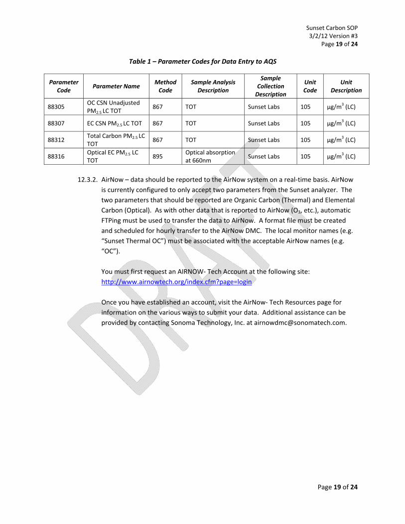
12.3.1. The Air Quality System (AQS) – data must be reported to AQS using the information
provided in Table 1. The table includes the parameter and method codes for loading
carbon data at local conditions from the Sunset Semi‐Continuous OC/EC sampler into
AQS. It also includes the unit code and description. The parameter codes that must be
reported for the study are thermal OC (88305), thermal EC (88307) and Optical EC
(88316). Total Carbon or TC (88312) is optional for reporting. For those that are
utilizing this SOP that are not participating in the Sunset Carbon Evaluation Project,
you can contact the AQS Team ([email protected]) for information about other
parameter codes that may be necessary for your specific sampling needs.
Sunset Carbon SOP 3/2/12 Version #3
Page 19 of 24
Page 19 of 24
Table 1 – Parameter Codes for Data Entry to AQS
Parameter Code
Parameter Name Method Code
Sample Analysis Description
Sample Collection Description
Unit Code
Unit Description
88305 OC CSN Unadjusted PM2.5 LC TOT
867 TOT Sunset Labs 105 µg/m3 (LC)
88307 EC CSN PM2.5 LC TOT 867 TOT Sunset Labs 105 µg/m3 (LC)
88312 Total Carbon PM2.5 LC TOT
867 TOT Sunset Labs 105 µg/m3 (LC)
88316 Optical EC PM2.5 LC TOT
895 Optical absorption at 660nm
Sunset Labs 105 µg/m3 (LC)
12.3.2. AirNow – data should be reported to the AirNow system on a real‐time basis. AirNow
is currently configured to only accept two parameters from the Sunset analyzer. The
two parameters that should be reported are Organic Carbon (Thermal) and Elemental
Carbon (Optical). As with other data that is reported to AirNow (O3, etc.), automatic
FTPing must be used to transfer the data to AirNow. A format file must be created
and scheduled for hourly transfer to the AirNow DMC. The local monitor names (e.g.
“Sunset Thermal OC”) must be associated with the acceptable AirNow names (e.g.
“OC”).
You must first request an AIRNOW‐ Tech Account at the following site:
http://www.airnowtech.org/index.cfm?page=login
Once you have established an account, visit the AirNow‐ Tech Resources page for
information on the various ways to submit your data. Additional assistance can be
provided by contacting Sonoma Technology, Inc. at [email protected].

Sunset Carbon SOP 3/2/12 Version #3
Page 20 of 24
Page 20 of 24
13. REFERENCES
Sunset Laboratory Inc. Semi‐Continuous Carbon Aerosol Analyzer Field Instrument Manual, April 2011.

Sunset Carbon SOP 3/2/12 Version #3
Page 21 of 24
Page 21 of 24
APPENDIX A OAQPS QUALITY CONTROL MAINTENANCE CHECK SHEET
FOR THE SUNSET OC/EC FIELD ANALYZER Analyzer Serial Number__________________________ Site:____________________________________
Date/Time of Arrival:_____________________________ Operator:________________________________
Allowed to Finish Sample Run Interrupted Sampling Cycle (Did Not Analyze)
Carrier Gases
Primary Pressure
(PSI) Action
Secondary Pressure
(PSI) Action
Adjustment Made? (Y/N)
He Order new cylinder if <1000 PSI Replace cylinder if <250 PSI**
Adjust to ~12 PSI (single analyzer) or ~20 PSI (collocated analyzers)
He/O2
He/CH4
**Must perform a multi-point calibration after changing the He/CH4 tank (See Appendix B)
Record the following Parameters: Laser Correction Value:_____________ (should be >0.90) Back Oven Temperature during Analysis: _____________ (should be ~870°C) Back Oven Temperature during Sampling: ____________ (should be ~500°C)
Y/N Comments
Analyzer Gas Flows fairly stable?
Blank Values < ± 0.3 µg C since last visit?
Weekly Tasks: Clean the Drop Out Tee Change the Filters, Run Fast-TC clean on Filters Manually Set Flows to Zero and Autozero, if necessary:
Gases Flows when Manually
Set to Zero Action
Auto zero Performed? (Y/N)
He1 cc/min Autozero Flows if any flows are >±0.5 cc/min (Cal Gas >±1 cc/min)
He Purge cc/min
He/Oxygen cc/min
Cal Gas cc/min
Shutdown the Software, Restart the Computer, Reopen the Software, do not Autostart Analyzer Verify the PSIG in Idle Mode is <2.75 (may need to replace oven if >3.5) PSIG=__________ Change Output Data File, Verify Status is “Checking” Sample Collection=__________
Bi-Weekly Tasks: Single Point External Standard (Table on Page 2) Change the File Name (if not writing to a new file daily and running on 1 hour sample period)
Monthly Tasks: Change Denuder Filter Strips Clean the Cyclone inlet Leak Check
Semi-Annual Tasks: Clean Inlet Tubing Multi Point External Calibration (Table on Page 2) Check flows within ± 2% (He1, HeOx, Cal Gas) & ± 5% (HePurge). Recalibrate if necessary

Sunset Carbon SOP 3/2/12 Version #3
Page 22 of 24
Page 22 of 24
OAQPS QUALITY CONTROL MAINTENANCE CHECK SHEET FOR THE SUNSET OC/EC FIELD ANALYZER
Comments:
SUCROSE INJECTIONS
Injection Number
Standard (µg C / µL)
Volume of Sample Injected
(µL)
Carbon Injected (µg)
Carbon Measured (µg)
Measured within ±5% of Injected?
(Y/N)
1
2
3
4
5
6
7
8
9
10
11
12
13
14
15
16
17
18
19
20

Sunset Carbon SOP 3/2/12 Version #3
Page 23 of 24
Page 23 of 24
Appendix B
Sucrose Spreadsheet Example for Standards

Sunset Carbon SOP 3/2/12 Version #3
Page 24 of 24
Page 24 of 24
Appendix C
Sucrose Spreadsheet Example for New Calibration Constant
NDIR Par File Example for Changing Calibration Constant
New Cal Constant Entered Here