draft - university of toronto t-space · draft 4 compares the hysteretic behavior of conventional...
TRANSCRIPT

Draft
Response modification factors for steel buckling restrained
braced frames designed as per NBCC 2010
Journal: Canadian Journal of Civil Engineering
Manuscript ID cjce-2014-0014.R3
Manuscript Type: Article
Date Submitted by the Author: 25-Apr-2016
Complete List of Authors: Moni, Moniruzzaman; The University of British Columbia, School of Engineering Moradi, Saber; The University of British Columbia, School of Engineering Alam, M. Shahria; The University of British Columbia, School of Engineering
Keyword: response-earthquake load < Struct.Eng. & Constr.Mate, structure - steel <
Struct.Eng. & Constr.Mate, structural engineering < Computer Applications
https://mc06.manuscriptcentral.com/cjce-pubs
Canadian Journal of Civil Engineering

Draft
1
Response modification factors for steel buckling restrained braced frames
designed as per NBCC 2010
School of Engineering, the University of British Columbia, Kelowna, BC, Canada V1V1V7
Moniruzzaman Moni
Graduate Research Assistant
School of Engineering
The University of British Columbia
1137 Alumni Avenue, EME 3213
Kelowna, BC, V1V1V7
Email: [email protected]
Saber Moradi
PhD candidate
School of Engineering
The University of British Columbia
1137 Alumni Avenue, EME 3213
Kelowna, BC, V1V1V7
Email: [email protected]
M. Shahria Alam*
Associate Professor, PEng.
School of Engineering
The University of British Columbia
1137 Alumni Avenue, EME 4225
Kelowna, BC, V1V1V7
TEL: (250) 807-9397 | Fax: (250) 807-9850 *Corresponding Author
Email: [email protected]
Word count: 9568
Page 1 of 44
https://mc06.manuscriptcentral.com/cjce-pubs
Canadian Journal of Civil Engineering

Draft
2
Response modification factors for steel buckling restrained braced frames
designed as per NBCC 2010
Moniruzzaman Moni, Saber Moradi, and M. Shahria Alam*
School of Engineering, the University of British Columbia, Kelowna, BC, Canada V1V1V7
Abstract: This paper evaluates the overstrength, ductility and response modification factors
for low to mid-rise Buckling Restrained Braced Frames (BRBFs) designed as per the
National Building Code of Canada (NBCC) 2010. In addition to nonlinear static pushover
analyses, dynamic time history analyses are performed to assess the seismic performance of
four-, six-, and eight-story BRBFs. Different bracing configurations, including chevron
(inverted-V) and split-X braces, are considered for the building frames with varied frame
span lengths of 6m and 8m. The results confirm that the prescribed design values for
overstrength and ductility factors provide reasonable estimations of the lower bound for these
factors. The response modification factor obtained in this study ranged from 4.8 to 6 for
different frames. The results also indicate that the response modification factor decreases
with the increase of story height and span length. Moreover, bracing configurations may
slightly affect the response modification factor of BRBFs.
Keywords: steel concentrically braced frame, buckling restrained braced frame, split-X
bracing, chevron bracing, seismic overstrength, ductility factor, response modification factor,
force reduction factor, seismic design, NBCC.
*Corresponding Author, Email: [email protected] Tel: +1.250.807.9397, Fax: +1.250.807.9850
Page 2 of 44
https://mc06.manuscriptcentral.com/cjce-pubs
Canadian Journal of Civil Engineering

Draft
3
Introduction
Steel concentrically braced frames are commonly used in buildings to resist lateral loads,
such as earthquakes. The design and fabrication of these systems are simple and the required
lateral strength and stiffness can be achieved at a low cost. Under seismic excitations,
conventional steel braces are expected to dissipate energy by yielding in tension and buckling
in compression (Tremblay et al. 1995). However, during past earthquakes, conventional steel
braced frames suffered extensive damage and bracing members, or their connections,
fractured (Tremblay et al. 1996). The poor performance of braced frames are attributed to
several factors, which include limited ductility or energy dissipation capacity, fracture of
connections, unsymmetrical behavior of braces in tension and compression, and buckling of
braces (Sabelli et al. 2003). In particular, the occurrence of buckling in bracing members
leads to a rapid degradation of story shear resistance and stiffness, and, consequently, the
appearance of large deformations under severe seismic loadings (Khatib et al. 1988, as
mentioned in Tremblay at al. 1995).
As an alternative to conventional braces for steel frames, researchers studied the
implementation of Buckling Restrained Braces (BRBs) in buildings (Clark et al. 1999). Figs.
1a, 1b show the components of a typical BRB. The BRB element consists of a ductile steel
core which is encased in a concrete/mortar filled steel tube. The yielding mechanism is
provided by the steel core while the buckling of the core is prevented by the tube (Uang and
Nakashima 2004). BRBs have the potential to exhibit a stable, symmetrical and repeatable
hysteresis while providing adequate ductility (Tremblay et al. 2006). Experimental studies
show that a properly designed BRBF can resist severe earthquakes with insignificant damage
while experiencing no stiffness or strength degradation (Fahnestock et al. 2007). Fig. 1c
Page 3 of 44
https://mc06.manuscriptcentral.com/cjce-pubs
Canadian Journal of Civil Engineering

Draft
4
compares the hysteretic behavior of conventional and buckling restrained bracing members.
A brief review of steel BRBFs can be found in Della Corte et al. (2011).
Several researchers have investigated the seismic behavior and design of BRBFs. Chao et al.
(2013) numerically showed the economical use of BRBs in buildings. The frames with a
hybrid bracing system (BRBs at lower story levels) exhibited a similar seismic performance
compared to that of frames having buckling restrained braces at all story levels. Dusicka et al.
(2013) studied an ultra-lightweight buckling-restrained brace which weighs 27% of a
traditional mortar-filled tube and 41% all-steel buckling-restrained brace configurations.
Palmer et al. (2013) examined the bidirectional behavior of BRBFs through experimental
tests. BRBs can also be used in conjunction with other damping or recentering devices (for
e.g. Miller et al. 2012).
There are several studies proposing and investigating the seismic design procedures for
BRBFs. Choi et al. (2006) studied the performance based design of BRBFs using a modified
energy-balance concept. The study by Bosco and Marino (2013) proposed and numerically
validated a design method for BRBFs. Lin et al. (2013) introduced a seismic design method
for corner gusset plates in steel BRBFs. There are some other studies aimed at evaluating the
design factors specifically for BRBFs (among others, Asgarian and Shokrgozar 2009).
Several studies have confirmed that the use of BRBs can improve the seismic response of
buildings. As a result, design guidelines and standards address the specifications for the
design of BRBFs. Most design guidelines allow for the reduction of design forces when using
the static equivalent force procedure (e.g., ATC-3 1978, as mentioned in Rainer 1987; NBCC
2010). In 2010, force modification factors for BRBFs were added to the NBCC 2010
(Mitchell et al. 2010). The force modification factor (R) includes two characteristics of a
structural system, including ductility and reserve strength. This design concept relies on the
Page 4 of 44
https://mc06.manuscriptcentral.com/cjce-pubs
Canadian Journal of Civil Engineering

Draft
5
inherent overstrength and ductility of the structure. In general, the structure can provide a
higher amount of strength than its predefined design value and it can sustain large inelastic
deformations without collapse (Kim and Choi 2005). The ductility and energy absorption of
the structure, its ability to withstand load, and its stiffness under reversed cyclic loading are
among the structural features supporting this concept (Mitchell et al. 2003). The 2010 NBCC
uses two separate force modification factors:
i) the overstrength factor (Ro) accounts for the dependable portion of reserve strength in
the structure, as mentioned in the 2010 NBCC. This factor can be calculated from the
ratio of the actual lateral strength (Vy) to the design lateral strength (Vd). Fig. 2
illustrates the base shear-roof displacement relationship generated from the pushover
response of a structure. The design and actual strengths along with the maximum roof
displacement (∆max) and the roof displacement at the yield points (∆y) are indicated in
Fig. 2.
ii) the ductility-related force modification factor (Rd) reflects the capability of the
structure to dissipate energy through inelastic behavior. There are several methods to
obtain the ductility factor. In this study, the method proposed by Miranda and Bertero
(1994) was used to calculate (Rd). To calculate the ductility factor (Rd), soil type,
ductility ratio (µ), and the natural period of the structure are considered.
The design base shear can be greatly reduced for a structural system having higher ductility
and overstrength factor. Consequently, this reduction leads to a decrease in the member sizes
of the structure. Hence, a more economical design can be obtained by accepting some
damages during an earthquake. The evaluation of the response modification factor is essential
in the seismic design of buildings as it shows the trade-off between inherent favourable
structural characteristics, such as ductility and accompanying damage, and the initial cost of
Page 5 of 44
https://mc06.manuscriptcentral.com/cjce-pubs
Canadian Journal of Civil Engineering

Draft
6
the structure (Rainer 1987). Previous research has shown that the reserve strength can
significantly affect the seismic behavior of BRBFs (Ariyaratana and Fahnestock 2011).
The 2010 NBCC prescribes 1.2 and 4 as the overstrength and ductility factor of BRBFs.
These are regardless of buildings height, span length, and bracing configuration. In this
paper, the seismic design factors, including ductility, overstrength, and response modification
factors for BRBFs designed as per NBCC 2010 were examined. In order to include the effects
of buildings height and span length, four-, six-, and eight-story frames with different span
lengths of 6m and 8m were considered in the study (herein, span length is the bay length of
BRBF). In addition, two different bracing configurations, including inverted-V chevron and
split-X were used for the frames. The overstrength and ductility of the BRBFs were evaluated
by performing nonlinear static pushover analyses. Furthermore, nonlinear time history
analyses were conducted to assess the dynamic responses of the frames. The capacity/demand
ratios of the BRBFs were obtained and discussed.
Design of frames
Twelve frame buildings with buckling-restrained braces were designed as per NBCC 2010
and CSA-S16-09 (CSA 2009) and their overstrength factors, ductility factors, and response
modification factors were evaluated. Fig. 3 shows the plan and elevation view of the steel
frames along with the span and height dimensions. All the frames have three bays in each
direction and a story height of 4 m. The total heights of the BRBFs considered here remain
less than 40 m (i.e. the height restriction for BRBFs specified in CSA-S16-09). The general
purpose structural program, SAP2000 (v15.0) was used to analyze and design the 3D
building models. The buildings were assumed to be located on a stiff soil (site class D) in
Vancouver. In the design process, the ductility and overstrength factors of 4.0 and 1.2 were
considered, respectively. A normal seismic importance factor (i.e. I=1.0) were assumed for
Page 6 of 44
https://mc06.manuscriptcentral.com/cjce-pubs
Canadian Journal of Civil Engineering

Draft
7
the buildings. The dead and live loads were considered as uniformly distributed loads of 4.8
and 1.9 kN/m2, respectively. The design was carried out assuming steel buckling restrained
braces for the frames. Modulus of elasticity, yield strength, and strain hardening of steel were
assumed to be 200,000 MPa, 350 MPa, and 0.5%, respectively. Table 1 lists the member
sizes for different steel BRBFs. The core steel area for the buckling-restrained bracing
members was determined based on the force in the bracing members from the analysis results
in SAP program. The analytical values were also manually verified through a static analysis.
The following formula was used to obtain the core steel area for the buckling-restrained
braces:
where is the axial force in the bracing member (in N) and is the yield strength of
steel material (in MPa). As an example, for the 4 story 6m span, the brace force is 329 kN,
thus the brace core area will be:
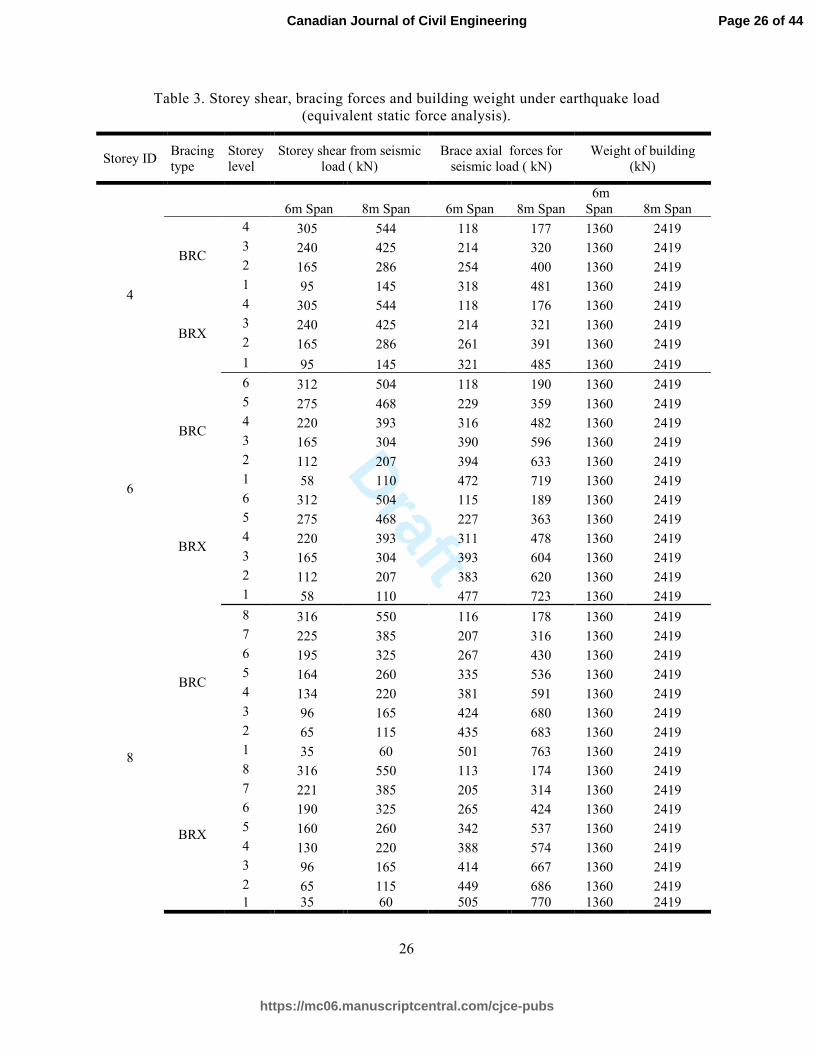
Table 3 lists the story shear and axial forces of the bracing members under earthquake
loading (equivalent static force analysis) as well as seismic weight of each floor. From Table
3, it is observed that the seismic load distributions of the bracing members are almost the
same for frames with different bracing configurations (less than 5% variation). However, as
seen in Table 1, the axial forces in BRX braces for buildings with the same span length are
larger compared to BRC braces, particularly at lower stories. Here, unlike BRC, BRX
configuration attracts more gravity forces because it connects two alternate levels in between
two column nodes where axial forces are being partially transferred through braces. Hence,
braces in BRX experience more forces compared to BRC.
Page 7 of 44
https://mc06.manuscriptcentral.com/cjce-pubs
Canadian Journal of Civil Engineering

Draft
8
Analytical modeling of frame structures
The finite element program, SeismoStruct (v7.0.3) was used to model the buckling restrained
braced frames and perform 2D analyses. The external braced frame shown in Fig. 3 was
considered for the numerical analyses. A uniaxial bilinear stress-strain model with kinematic
strain hardening was used to capture the steel behavior. The strain hardening parameter (i.e.,
the ratio between the post-yield stiffness and initial elastic stiffness of steel material) was
assigned as 0.5%. Displacement-based frame elements with fiber sections were employed to
model the beam and column members. The buckling restrained braces were modeled using
truss elements having bilinear hysteretic behavior (with strain hardening of 2%). Only the
steel core of BRB was modeled neglecting the other parts, such as concrete and debonding
materials. Moreover, the behavior of a BRB was assumed to be similar in tension and
compression. The cross sectional areas of steel core considered for the buckling restrained
braces are provided in Table 1.
Modal analysis
Eigenvalue analyses were performed to determine the natural periods of the BRBFs. Table 2
presents the fundamental periods of the frame structures obtained from modal analysis along
with the values calculated as per NBCC 2010. Eq. [1] is the empirical equation proposed by
NBCC 2010:
[1] T = 0.025 hn
Where T is the fundamental period of the structure in (sec) and hn is the height of the
structure in meter. It can be observed that the equation provided in the code underestimates
the period of the BRBFs. It should be also noted that the fundamental periods of the
structures are not affected by varying span length and bracing configuration.
Page 8 of 44
https://mc06.manuscriptcentral.com/cjce-pubs
Canadian Journal of Civil Engineering

Draft
9
Nonlinear static pushover analyses
Static nonlinear pushover analyses were carried out to evaluate the overstrength factor (Ro)
and ductility (µ) of the BRBFs. Lateral loads with a triangular distribution over the building
height were considered at each story level, in which the horizontal load is zero at the base of
the building and peak load is applied at the roof level. Fig. 4 shows the pushover response
curves for different BRBFs. The pushover analysis continued until the maximum interstory
drift in the frame reached the design drift limit of 2.5% or until non-convergence happened.
As can be seen, the elastic stiffness and ultimate strength of the building increases by
increasing the span length.
In most cases, similar base shear capacities were observed for the same BRBFs having
different bracing configuration (with chevron- or X-braces). The maximum difference was
observed as 10% for four-story BRBFs with 6m span. The inter story drift distributions of the
frames are depicted in Fig. 5 for four-, six- and eight-story frames, respectively. Here, the
inter-story drift represents the relative movement of the floor level either at the stage of
collapse or at the code specified maximum allowable story drift (i.e. 2.5%), whichever
governs.
Overstrength factors
As depicted in Fig. 2, overstrength factor (Ro) is the ratio of the maximum base shear
capacity or actual response to the design base shear. The overstrength factors were calculated
using the pushover curves. Table 4 lists important characteristics derived from the pushover
response. The displacement ductility (µ) which is defined as the ratio of the maximum
displacement to the yield displacement was also calculated from the pushover curve. Here,
the maximum displacement (∆max) is defined as the displacement corresponding to the
Page 9 of 44
https://mc06.manuscriptcentral.com/cjce-pubs
Canadian Journal of Civil Engineering

Draft
10
maximum base shear or when the maximum interstory drift reaches 2.5%. The displacement
at the yield point (∆y) is observed from the idealized pushover curve. The design base shear
values (Vd) for the BRBFs are also listed in Table 4. The base shear strength is higher for a
similar BRBF with greater bay length where the longer-bay BRBF is designed with higher
steel core areas (see Table 1).
The overstrength factors, defined as the ratio between the actual base shear capacity (Vy) and
the design base shear, are also provided for all the frames. The base shear capacity is
observed by performing pushover analysis and it is shown in Table 4. From this table, it is
observed that the actual base shear capacity of the BRBFs is increased for buildings with
longer spans. In almost all cases, higher BRBFs showed greater base shear capacities. The
actual base shear capacity is used to calculate the over strength factor of the considered
frames. Fig. 6 shows the overstrength factors for the BRBFs with chevron inverted-V and X-
braces, ranging from 1.20 to 1.48, which means that the lateral capacities are from 1.20 to
1.48 times the design base shear. The minimum overstrength factor observed in this study is
found to be the same as the code prescribed value. A higher overstrength factor than the
code-specified design overstrength value (i.e. Ro = 1.2) indicates the conservative view of the
NBCC 2010. It is important to note that in seismic design codes, a conservatively lower Ro is
stated to account for several uncertain factors influencing the reserve strength in a building.
These factors, which may not be explicitly considered in numerical studies, include the
effects of member sizes exceeding the design requirements, effects of structural redundancy,
effects of non-structural elements, and uncertainty associated with determining the actual
material yield strength, resistance and strain hardening (Elnashai and Sarno 2008; Mitchell et
al. 2003).
Page 10 of 44
https://mc06.manuscriptcentral.com/cjce-pubs
Canadian Journal of Civil Engineering

Draft
11
In general, the overstrength factor decreases with increase in the bay length and the building
height. Moreover, almost similar overstrength factors were obtained for buildings with
different bracings, where the maximum variation was 10.44%. Therefore, the overstrength of
the BRBF buildings considered in this study can be considered independent of the bracing
configuration. The brace length, angle of brace inclination, and bay size are the same in both
frames with either chevron inverted-V or X-braces, half of them are in tension and half in
compression at any given time. Therefore, it is reasonable to expect essentially similar
behavior for these buildings.
Ductility factors
In this section, the ductility factors (Rµ) for the BRBFs were obtained using the equations
proposed by Miranda and Bertero (1994). This method includes characteristics such as soil
conditions, ductility (µ) and natural period of the structure (Τ). For stiff soil:
[2]
[3]
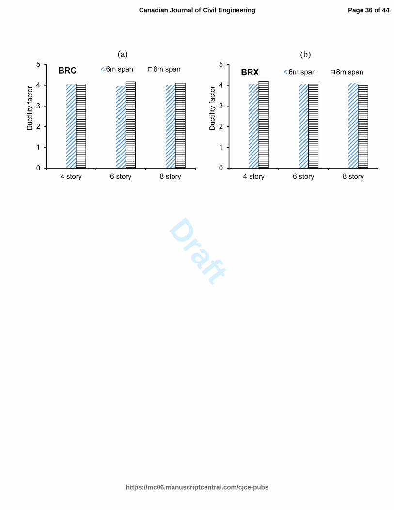
The ductility factors calculated based on this method are provided in Fig. 7. It can be
observed that BRBFs with longer spans typically result in a higher ductility factor. The
highest ductility factor was obtained as 4.18 for four-story BRBFs with 8m span length and
X- braces. The smallest amount of ductility factor was 3.97 for six-story BRBFs of 6m span
with chevron braces. When comparing the ductility factors for BRBFs of the same height
with different bracing configurations, the maximum difference was 5%. Therefore, the
bracing configuration does not affect the ductility factor of the BRBFs considered in this
paper.
Page 11 of 44
https://mc06.manuscriptcentral.com/cjce-pubs
Canadian Journal of Civil Engineering

Draft
12
Response modification factors
The response modification factor for the BRBFs was obtained by multiplying the
overstrength factor with the ductility factor for each frame, which are listed in Table 5. The
response modification factors for the frames with chevron braces and X-braces are compared
in Fig. 8. Generally, lower response modification factors were obtained for BRBFs with
higher heights. All the BRBFs, showed response modification factors equal or higher than the
NBCC 2010 prescribed value of Rµ Ro=4.8 for BRBFs. Among the BRBFs considered, the
six and eight-story 6m-span chevron braced frame exhibited a minimum response
modification factor equal to the prescribed value of 4.8 in the 2010 NBCC. Based on the
results, the maximum response modification factor was obtained as high as 6.17 for four-
story X-BRBF with 6m span length. When comparing the response modification factors for
BRBFs of the same height with different bracing configuration, a maximum difference of
11% was observed. Hence, the response modification factor of BRBFs may be slightly
affected by the bracing configuration. It can be also concluded that the response modification
factor decreased with the increase of story height and span length.
Nonlinear time history analysis
To assess the seismic performance of the BRBFs, nonlinear dynamic time history analyses
were performed for the 2D frames. Nine real records and an artificial ground motion
developed by Atkinson (2009) for Vancouver were used. Some characteristics of the selected
ground motion records are presented in Table 5. These records were chosen as they could
represent the seismic events for the location of the designed structures. The ratio between the
peak ground acceleration (PGA) and peak ground velocity (PGV) which indicates the
frequency content of a seismic motion is around 1.0 for the western part of Canada
Page 12 of 44
https://mc06.manuscriptcentral.com/cjce-pubs
Canadian Journal of Civil Engineering

Draft
13
(Naumoski et al. 1988). As can be seen in Table 6, the PGA/PGV ratio of the records varies
between 0.8 and 1.2. In the following sections, the seismic performance of the BRBFs is
discussed in terms of interstory drift demand, roof drift demand, and base shear demand.
Inter-story drift demand
The inter-story drift demands were calculated from the dynamic time history analyses of the
frame buildings under the ensemble of earthquake data. For the sake of brevity, the drift
demand distribution plot is presented only for four-story chevron BRBFs (Fig. 9). In this
figure, the demand values are illustrated for different earthquake records as well as the
average interstory drift demand over the height of the buildings. Based on the average drift
demands for the four-story chevron BRBFs (Fig. 9), the maximum demand was generated at
the first floor level for the four-story chevron BRBF with 8m span, while the BRC frames
with less span lengths of 6m experienced the peak demand at their second floor levels.
By changing the bracing configuration to X-braces, the concentration of the drift demands
remains on the same story level, except for the four-story X-BRBF frame with 6m span
length.
For the six-story chevron-BRBFs with 6m span lengths, the peak average demand was
produced at the 5th
floor level, whereas in the case of the 6BRC frame with 8m span length,
the 2nd
story level exhibited the maximum interstory demand.
For all the six-story BRBFs with X-braces (i.e. 6BRX), the peak interstory drift demands
were generated in the 4th
floor level.
The 3rd
, and 4th
floor experienced the peak average interstory drift demand in the eight-story
chevron-BRBFs with the span lengths of 6m and 8m, respectively.
Page 13 of 44
https://mc06.manuscriptcentral.com/cjce-pubs
Canadian Journal of Civil Engineering

Draft
14
In all the eight-story X-BRBFs, the peak interstory demand was in the 4th
floor. Generally, it
can be mentioned that the interstory drift demand concentration shifts to higher story levels as
the height of the BRBF increases. For the BRBFs of the same height, the story level at which
the drift demand concentration occurred either shifts to lower stories or remain unchanged
when increasing the span length.
Roof drift demand
Figs. 10 and 11 show the roof drift demands for both types of BRBFs of different stories and
span lengths under various earthquake records. In general, the roof drift demand increases for
BRBFs of lower stories. The roof drift demand for BRBFs with chevron braces is almost the
same as that of BRBFs with X-braces. Fig. 12 depicts the roof drift capacity/demand ratios
for the frames with different heights and span lengths. The global drift of the building at the
maximum base shear from the pushover analysis was considered as the drift capacity of the
frame. Further, the drift demand is defined as the average of the maximum drifts at the roof
of the building subjected to earthquakes scaled to represent the design spectrum. As can be
seen in Fig. 12, all the designed BRBFs possess higher roof drift capacities than their
demands under earthquakes. The roof drift capacity demand ratio is higher for 8m span for
both four- and six-story chevron and X- braced frames. However, in the case of eight-story
frames, a higher capacity/demand ratio is observed for 6m span frames.
Base shear demand
The calculated base shear demands based on the nonlinear time history analyses of the
BRBFs are depicted in Figs. 13 and 14 for chevron and X-braced frames with different
heights and span lengths. The maximum base shear generated in the building frame subjected
to the earthquake loading was considered as the base shear demand value. In Figs. 13 and 14,
Page 14 of 44
https://mc06.manuscriptcentral.com/cjce-pubs
Canadian Journal of Civil Engineering

Draft
15
the base shear capacities of the frames were also indicated. The average base shear demands
for frames of 6m long span are less compared to that of 8m span frame for each story type.
Therefore, it can be stated that the frames with larger span lengths experienced higher base
shear demands. In addition, the demand generally increases with increasing the number of
stories. The results also show that the base shear demand is not much affected by the bracing
configuration of the BRBFs analyzed in this study. The capacity demand ratios in terms of
base shear is presented in Fig. 15. As can be seen, the capacity/demand ratios for the 6m span
frames is higher compared to those of 8m span frames in case of four- and six-story frames.
The base shear capacity demand ratio is higher for 8m span in case of eight-story chevron and
X-braced frames. In addition, the base shear capacity/demand ratio decreases with the
increase of building height for the chevron braced frames but it may remain same for X-
braced frames. Fig. 15 also indicates that all the BRBFs possess higher base shear capacities
compared to the base shear demands generated under the earthquake excitations.
Conclusions
This paper numerically evaluated the force reduction factors for steel Buckling Restrained
Braced Frames (BRBF) designed as per the 2010 NBCC. Four-, six-, and eight-story
buildings with different span lengths of 6m and 8m were designed and analyzed. Two
different bracing configurations, including chevron inverted-V and split-X braces, were also
considered for the BRBFs. Overstrength, ductility, and response modification factors for
twelve BRBFs were assessed by performing nonlinear static pushover analyses. Eigen value
analyses were also performed to obtain the natural periods of the BRBFs. In order to examine
the seismic performance of the designed BRBFs, nonlinear time history analyses were
conducted using several ground motion records. Capacity/demand ratios of the BRBFs in
Page 15 of 44
https://mc06.manuscriptcentral.com/cjce-pubs
Canadian Journal of Civil Engineering
Draft
16
terms of interstory drift, roof drift, and base shear were obtained and discussed. The
following conclusions are drawn:
• The equation provided in the 2010 NBCC underestimated the natural periods of the
BRBFs. The fundamental periods of the structures were not affected by varying span
length and bracing configuration.
• The elastic stiffness and maximum base shear capacity of the BRBFs increased when
the span length of the building was increased. In almost all cases, higher BRBFs
showed greater base shear capacities.
• The overstrength factors obtained for the BRBFs ranged from 1.20 to 1.48. These
overstrength values are higher than those prescribed in the 2010 NBCC for BRBFs
(i.e., 1.2). In general, the overstrength factor decreased with the increase in the span
length and the increase in the building height. The overstrength of the BRBF
buildings considered in this study was independent of the bracing configuration.
• The ductility factors for BRBFs calculated based on the method by Miranda and
Bertero (1994) were in the range of 3.97 to 4.18. All the ductility factors are equal or
higher than 4, which is stated in the 2010 NBCC for BRBFs. In general, it can be
noted that BRBFs with longer spans possess a higher ductility factor. Furthermore,
the bracing configuration of the BRBFs may affect the ductility factor.
• The response modification factors obtained from the multiplication of the
overstrength and ductility factor were in the range of 4.8 to 6.0. The combined use of
overstrength and ductility factor, provided in the 2010 NBCC, results in a response
modification factor of 4.8 (=1.2×4.0). Therefore, it can be concluded that the code
prescribed value of 4.8 is somewhat a lower bound for the response modification
Page 16 of 44
https://mc06.manuscriptcentral.com/cjce-pubs
Canadian Journal of Civil Engineering

Draft
17
factor of the BRBF. Additionally, the results indicate that the response modification
factor decreased with the increase of story height and span length. The response
modification factor may be slightly affected by the bracing configuration.
• From the nonlinear time history analyses of the BRBFs, it was observed that the
interstory drift demand concentration shifts to higher story levels as the height of the
building increases. When increasing the span length of the BRBFs of the same
height, the concentration of drift demand either remained on the same story level or
shifted to lower heights.
• The base shear demand of the BRBFs generally increased as the building height and
span length increased. Moreover, the capacity/demand ratios of the BRBFs showed
that all the frames considered in this study exhibited higher roof drifts as well as base
shear capacities compared to the demand values.
Further studies can be done to assess the response modification factors for BRBFs with
different design details such as floor height. To confidently evaluate the response
modification factors for BRBFs, more accurate modeling details associated with the buckling
restrained braces can be also included in the analysis and design of such buildings.
Acknowledgement
The financial contribution of Natural Sciences and Engineering Research Council (NSERC)
of Canada through Discovery Grant was critical to conduct this research and is gratefully
acknowledged.
Page 17 of 44
https://mc06.manuscriptcentral.com/cjce-pubs
Canadian Journal of Civil Engineering

Draft
18
References
Alam, M.S., Moni, M., and Tesfamariam, S. 2012. Seismic overstrength and ductility of
concrete buildings reinforced with superelastic shape memory alloy rebar.
Engineering Structures, 34: 8-20.
Ariyaratana, C., and Fahnestock, L.A. 2011. Evaluation of buckling-restrained braced frame
seismic performance considering reserve strength. Engineering Structures, 33(1), 77-
89.
Asgarian, B., and Shokrgozar, H.R. 2009. BRBF response modification factor. Journal of
Constructional Steel Research, 65(2): 290-298.
ATC-3. 1978. Tentative provisions for the development of seismic regulations for buildings.
ATC-3-06, Applied Technology Council, Redwood City, California, 45–53.
Atkinson, G.M. 2009. Earthquake time histories compatible with the 2005 National building
code of Canada uniform hazard spectrum. Canadian Journal of Civil Engineering,
36(6): 991-1000.
Bosco, M., & Marino, E. M. 2013. Design method and behavior factor for steel frames with
buckling restrained braces. Earthquake Engineering & Structural Dynamics. 42:1243–
1263.
Chao, S.H., Karki, N.B., and Sahoo, D.R. 2013. Seismic Behavior of Steel Buildings with
Hybrid Braced Frames. Journal of Structural Engineering, 139(6): 1019-1032.
Choi, H., Kim, J., and Chung, L. 2006. Seismic design of buckling-restrained braced frames
based on a modified energy-balance concept. Canadian Journal of Civil Engineering,
33(10): 1251-1260.
Clark, P., Aiken, I., Kasai, K., Ko, E., and Kimura, I. 1999. Design procedures for buildings
incorporating hysteretic damping devices. In Proceedings 68th Annual Convention.
355-371.
Page 18 of 44
https://mc06.manuscriptcentral.com/cjce-pubs
Canadian Journal of Civil Engineering

Draft
19
CSA. 2009. Design of steel structures. CSA Standard S16-09. Canadian Standards
Association, Rexdale, Ont.
Della Corte, G., D’Aniello, M., Landolfo, R., and Mazzolani, F. M. 2011. Review of steel
buckling‐restrained braces. Steel Construction, 4(2): 85-93.
Dusicka, P., and Tinker, J. 2013. Global Restraint in Ultra-Lightweight Buckling-Restrained
Braces. Journal of Composites for Construction, 17(1): 139-150.
Elnashai, A. & Sarno, L. Di, 2008. Fundamentals of earthquake engineering, John Wiley &
Sons, Ltd, Publication.Fahnestock, L.A., Sause, R., and Ricles, J.M. 2007. Seismic
response and performance of buckling-restrained braced frames. Journal of Structural
Engineering, 133(9): 1195-1204.
Kim, J., and Choi, H. 2005. Response modification factors of chevron-braced frames.
Engineering Structures, 27:285–300.
Khatib, I.F., Mahin, S.A., and Pister, K.S. 1988. Seismic behavior of concentrically braced
steel frames. Earthquake Engineering Research Center, University of California,
Berkeley, Calif., Report NO. UCBIEERC-88/01.
Lin, P.C., Tsai, K.C., Wu, A.C., & Chuang, M.C. 2013. Seismic design and test of gusset
connections for buckling‐restrained braced frames. Earthquake Engineering &
Structural Dynamics. doi: 10.1002/eqe.2360
Miranda, E. and Bertero, V.V. 1994. Evaluation of strength reduction factors for earthquake-
resistant design. Earthquake Spectra, EERI, 10(2): 357-379.
Mitchell, D., Tremblay, R., Karacabeyli, E., Paultre, P., Saatcioglu, M., and Anderson, D.L.
2003. Seismic force modification factors for the proposed 2005 edition of the
National Building Code of Canada. Canadian Journal of Civil Engineering, 30(2),
308-327.
Page 19 of 44
https://mc06.manuscriptcentral.com/cjce-pubs
Canadian Journal of Civil Engineering

Draft
20
Mitchell, D., Paultre, P., Tinawi, R., Saatcioglu, M., Tremblay, R., Elwood, K., Adams, J.,
and DeVall, R. 2010. Evolution of seismic design provisions in the National building
code of Canada. Canadian Journal of Civil Engineering, 37(9): 1157-1170.
Miller, D.J., Fahnestock, L.A., and Eatherton, M.R. 2012. Development and experimental
validation of a nickel–titanium shape memory alloy self-centering buckling-restrained
brace. Engineering Structures, 40: 288-298.
Naumoski, N., Tso, W.K., and Heidebrecht, A.C. 1988. A selection of representative strong
motion earthquake records having different A/V ratios. Earthquake Engineering
Research Group, Department of Civil Engineering, McMaster University, Hamilton,
ON Canada. EERG Report 88-01.
NBCC. 2010. National Building Code of Canada. Institute for Research in Construction,
National Research Council of Canada. Ottawa, Ont.
Palmer, K.D., Roeder, C.W., Lehman, D.E., Okazaki, T., and Shield, C. 2013. Experimental
Performance of Steel Braced Frames Subjected to Bidirectional Loading. Journal of
Structural Engineering, 139(8): 1274-1284.
Rainer, J.H., 1987. Force reduction factors for the seismic provisions of the National Building
Code of Canada. Canadian Journal of Civil Engineering, 14: 447-454.
Sabelli, R., Mahin, S., and Chang, C. 2003. Seismic demands on steel braced frame buildings
with buckling-restrained braces. Engineering Structures, 25(5): 655-666.
SAP2000 v15.0, Computers and structures, Inc. 1995 University Ave. Berkeley, California,
94704.
SeismoStruct v7.0.3, 2015. A computer program for static and dynamic nonlinear analysis of
framed structures. www.seismosoft.com
Page 20 of 44
https://mc06.manuscriptcentral.com/cjce-pubs
Canadian Journal of Civil Engineering

Draft
21
Tremblay, R., Filiatrault, A., Timler, P., and Bruneau, M. 1995. Performance of steel
structures during the 1994 Northridge earthquake. Canadian Journal of Civil
Engineering, 22(2): 338-360.
Tremblay, R., Filiatrault, A., Bruneau, M., Nakashima, M., Prion, H.G., and DeVall, R. 1996.
Seismic design of steel buildings: lessons from the 1995 Hyogo-ken Nanbu
earthquake. Canadian Journal of Civil Engineering, 23(3): 727-756.
Tremblay, R., Bolduc, P., Neville, R., and DeVall, R. 2006. Seismic testing and performance
of buckling-restrained bracing systems. Canadian Journal of Civil Engineering, 33(2):
183-198.
Uang CM & Nakashima M. 2004. Steel buckling-restrained braced frames. Chapter 16 in
Earthquake Engineering: Recent Advances and Applications, CRC Press, Boca Raton,
FL.
Page 21 of 44
https://mc06.manuscriptcentral.com/cjce-pubs
Canadian Journal of Civil Engineering

Draft
22
List of Tables
Table 1. Design summary of different types of buildings (combined loading).
Table 2. Fundamental period of the structures.
Table 3. Storey Shear, bracing forces, and building weight under earthquake loading
(equivalent static force analysis).
Table 4. Overstrength factor and ductility.
Table 5. Response modification factor for model structures.
Table 6. Ensemble of ground motion records.
Page 22 of 44
https://mc06.manuscriptcentral.com/cjce-pubs
Canadian Journal of Civil Engineering

Draft
23
Figure Captions
Fig. 1. (a) Typical buckling restrained bracing element and (b) cross section A-A and (c)
Hysteretic behavior of conventional bracing and bucking restrained bracing members
under cyclic loading.
Fig. 1. Lateral load–roof displacement relationship of a structure (Alam et al. 2012, with
permission).
Fig. 3. (a) Plan of the buildings; and elevation of the (b) 4 story (c) 6 story and (d) 8 story
buildings.
Fig. 4. Pushover response curves for (a) four-story (b) six-story and (c) eight-story BRBFs
with chevron-braces (left) or X-braces (right).
Fig. 5. Interstory drift distributions for (a) four-story (b) six-story and (c) eight-story BRBFs
with chevron-braces (left) or X-braces (right).
Fig. 6. Overstrength factor of BRBFs with: (a) chevron bracing; (b) X-bracing.
Fig. 7. Ductility factor of the BRBFs with: (a) chevron bracing; (b) X-bracing.
Fig. 8. Response modification factor of BRBFs with: (a) chevron bracing; (b) X-bracing.
Fig. 2. Inter-story drift demand for 4-story chevron braced (a) 6m span and (b) 8m span.
Fig. 10. Roof drift demand for (a) 4-story, (b) 6-story and (c) 8-story chevron braced frame
Fig. 11. Roof drift demand for (a) 4-story, (b) 6-story and (c) 8-story X-braced frames.
Fig. 12. Roof drift capacity/demand ratio of (a) chevron braced frames and (b) X-braced
frames.
Fig. 13. Base shear demand for (a) 4-story, (b) 6-story and (c) 8-story BRBFs with chevron
braces.
Fig. 14. Base shear demand for (a) 4-story, (b) 6-story and (c) 8-story BRBFs with X-braces.
Fig. 15. Base shear capacity/demand ratio of (a) chevron braced frames and (b) X-braced
frames.
Page 23 of 44
https://mc06.manuscriptcentral.com/cjce-pubs
Canadian Journal of Civil Engineering

Draft
24
Tables
Table 1. Design summary of different types of buildings (combined loading).
Story
ID
Span
length
(m)
Floor
level
Braced bay
Interior
columns
Braced bay
exterior
columns
Steel girder
Axial force
for bracing
(BRC)
BRB steel
core area
(mm2)
(BRC)
Axial
force for
bracing
(BRX)
BRB steel
core area
(mm2)
(BRX)
4
6 1~2 W460×113 W410×74 W410×46 329 1044 388 1231
2~4 W460×60 W360×51 W410×46 218 692 207 657
8 1~2 W530×150 W460×106 W410×54 497 1577 581 1844
2~4 W530×74 W410×74 W410×54 330 1048 379 1203
6
6
1~2 W530×150 W530×101 W410×46 495 1571 589 1869
2~4 W530×72 W410×54 W410×46 303 1152 513 1628
5~6 W460×60 W360×51 W410×46 185 587 263 834
8
1~2 W610×415 W460×128 W410×54 762 2177 814 2325
2~4 W530×109 W410×85 W410×54 590 590 776 2217
5~6 W530×74 W410×60 W410×54 320 320 423 1208
8
6
1~2 W530×248 W410×106 W410×46 514 1631 605 1920
2~4 W530×101 W410×85 W410×46 450 1428 583 1850
5~6 W410×74 W410×67 W410×46 350 1111 459 1457
7~8 W410×46 W410×46 W410×46 220 698 250 794
8
1~2 W920×725 W460×128 W410×54 779 2473 844 2680
2~4 W610×155 W410×85 W410×54 701 2225 794 2520
5~6 W610×101 W410×60 W410×54 350 1746 602 1911
7~8 W530×74 W410×60 W410×54 326 1035 291 923
Page 24 of 44
https://mc06.manuscriptcentral.com/cjce-pubs
Canadian Journal of Civil Engineering

Draft
25
Table 2. Fundamental period of the structures.
Span length
(m) 6 8
Bracing BRC BRX BRC BRX Empirical equation
# Story
4 0.57 0.57 0.57 0.57 0.4
6 0.72 0.72 0.72 0.72 0.6 8 0.92 0.92 0.92 0.92 0.8
Page 25 of 44
https://mc06.manuscriptcentral.com/cjce-pubs
Canadian Journal of Civil Engineering
Draft
26
Table 3. Storey shear, bracing forces and building weight under earthquake load
(equivalent static force analysis).
Storey ID Bracing
type Storey
level Storey shear from seismic
load ( kN) Brace axial forces for
seismic load ( kN) Weight of building
(kN)
6m Span 8m Span 6m Span 8m Span 6m
Span 8m Span
4
BRC
4 305 544 118 177 1360 2419
3 240 425 214 320 1360 2419
2 165 286 254 400 1360 2419
1 95 145 318 481 1360 2419
BRX
4 305 544 118 176 1360 2419
3 240 425 214 321 1360 2419
2 165 286 261 391 1360 2419
1 95 145 321 485 1360 2419
6
BRC
6 312 504 118 190 1360 2419
5 275 468 229 359 1360 2419
4 220 393 316 482 1360 2419
3 165 304 390 596 1360 2419
2 112 207 394 633 1360 2419
1 58 110 472 719 1360 2419
BRX
6 312 504 115 189 1360 2419
5 275 468 227 363 1360 2419
4 220 393 311 478 1360 2419
3 165 304 393 604 1360 2419
2 112 207 383 620 1360 2419
1 58 110 477 723 1360 2419
8
BRC
8 316 550 116 178 1360 2419
7 225 385 207 316 1360 2419
6 195 325 267 430 1360 2419
5 164 260 335 536 1360 2419
4 134 220 381 591 1360 2419
3 96 165 424 680 1360 2419
2 65 115 435 683 1360 2419
1 35 60 501 763 1360 2419
BRX
8 316 550 113 174 1360 2419
7 221 385 205 314 1360 2419
6 190 325 265 424 1360 2419
5 160 260 342 537 1360 2419
4 130 220 388 574 1360 2419
3 96 165 414 667 1360 2419
2 65 115 449 686 1360 2419 1 35 60 505 770 1360 2419
Page 26 of 44
https://mc06.manuscriptcentral.com/cjce-pubs
Canadian Journal of Civil Engineering

Draft
27
Table 4. Over-strength factor and ductility.
Storey Bracing
types
Span
length (m)
Actual
strength Vy (kN)
Design
strength Vd (kN)
Over-
strength factor Ro
Maximum
displacement ∆max (mm)
Yield
displacement ∆y (mm)
Ductility
µ
4
BRC 6 1080 805 1.34 235 50 4.70
8 1736 1400 1.24 250 53 4.72
BRX 6 1190 805 1.48 260 55 4.73
8 1680 1400 1.20 245 50 4.90
6
BRC 6 1385 1142 1.21 275 67 4.10
8 2397 1986 1.21 290 67 4.33
BRX 6 1440 1142 1.26 265 63 4.21
8 2393 1986 1.20 290 69 4.20
8
BRC 6 1473 1230 1.20 440 120 3.67
8 2504 2080 1.20 380 102 3.73
BRX 6 1575 1230 1.28 575 153 3.76
8 2493 2080 1.20 425 115 3.70
Page 27 of 44
https://mc06.manuscriptcentral.com/cjce-pubs
Canadian Journal of Civil Engineering

Draft
28
Table 5. Response modification factor for model structures.
Storey Bracing
types
Span
length
(m)
Over-
strength
factor, Ro
Ductility
Reduction
Factor, Rµ
Response
Modification Factor
4
BRC 6 1.34 4.04 5.4
8 1.24 4.06 5.0
BRX 6 1.48 4.06 6.0
8 1.20 4.18 5.0
6
BRC 6 1.21 3.97 4.8
8 1.21 4.16 5.0
BRX 6 1.26 4.06 5.1
8 1.20 4.05 4.9
8
BRC 6 1.20 4.02 4.8
8 1.20 4.08 4.9
BRX 6 1.28 4.11 5.3
8 1.20 4.05 4.9
Page 28 of 44
https://mc06.manuscriptcentral.com/cjce-pubs
Canadian Journal of Civil Engineering

Draft
29
Table 6. Ensemble of ground motion records.
No. Earthquake Station Magni-
tude PGA (g)
PGA/PGV (sec
-1)
Data Source
1 Artificial (ART) - 6.5 0.35 - Atkinson (2009)
2 ATS, Kocaeli, 199/08/17 ATS-UP, 150 7.8 0.67 0.93 PEER*
3 BTS, Kocaeli, Turkey
1999/08/17
Botas 7.8 0.62 1.0 PEER*
4 Chi-Chi,Taiwan. 1999/09/20 CHY-006 7.6 0.63 0.81 PEER*
5 ChiChi-longt,Taiwan.
1999/09/21 Unknown 7.6 0.43 1.13 PEER*
6 Chi-Chi,Taiwan. 1999/09/20 CHY019-E 7.6 0.63 0.83 PEER*
7 Chi-Chi,Taiwan. 1999/09/20 CHY019-N 7.6 0.7 1.0 PEER*
8 Victoria, Mexico 6/9/1980 3:02 VICT/HPB0006.4 0.95 0.86 PEER*
9 Loma Prieta 1989/10/18 00:05 16 LGPC 6.9 1.11 - PEER*
10 Chi-Chi,Taiwan. 1999/09/20 TTN042-N 7.6 0.65 1.0 PEER*
* http://peer.berkeley.edu (PEER strong ground motion database 2007)
Page 29 of 44
https://mc06.manuscriptcentral.com/cjce-pubs
Canadian Journal of Civil Engineering

Draft
(a)
A
A
(b)
Steel core
Debonding
material
Steel jacket
Concrete
mortar
(c)
Page 30 of 44
https://mc06.manuscriptcentral.com/cjce-pubs
Canadian Journal of Civil Engineering

Draft
Fig. 2. Lateral load–roof displacement relationship of a structure (Alam et al. 2012, with permission). 123x77mm (220 x 220 DPI)
Page 31 of 44
https://mc06.manuscriptcentral.com/cjce-pubs
Canadian Journal of Civil Engineering

Draft
Fig. 3. (a) Plan of the buildings; and elevation of the (b) 4 story (c) 6 story and (d) 8 story buildings. 73x97mm (216 x 216 DPI)
Page 32 of 44
https://mc06.manuscriptcentral.com/cjce-pubs
Canadian Journal of Civil Engineering

Draft0
500
1000
1500
2000
2500
3000
0 100 200 300 400 500 600
Base shear (kN)
Roof displacement (mm)
6 BRC
6m span
8m span
0
500
1000
1500
2000
2500
3000
0 100 200 300 400 500 600
Base shear (kN)
Roof displacement (mm)
6 BRX6m span
8m span
0
500
1000
1500
2000
2500
3000
0 100 200 300 400 500 600
Base shear (kN)
Roof displacement (mm)
8 BRC6m span
8m span
0
500
1000
1500
2000
2500
3000
0 100 200 300 400 500 600
Base shear (kN)
Roof displacement (mm)
8 BRX6m span
8m span
0
500
1,000
1,500
2,000
2,500
3,000
0 100 200 300 400 500 600
Base shear (kN)
Roof displacement (mm)
4 BRC 6m span8m span
0
500
1000
1500
2000
2500
3000
0 100 200 300 400 500 600
Base shear (kN)
Roof displacement (mm)
4 BRX 6m span8m span
(a)
(b)
(c)
Page 33 of 44
https://mc06.manuscriptcentral.com/cjce-pubs
Canadian Journal of Civil Engineering

Draft
Fig. 5. Interstory drift distributions for (a) four-story (b) six-story and (c) eight-story BRBFs with chevron-braces (left) or X-braces (right).
158x218mm (96 x 96 DPI)
Page 34 of 44
https://mc06.manuscriptcentral.com/cjce-pubs
Canadian Journal of Civil Engineering

Draft
0
1
2
4 story 6 story 8 story
Overstrength factor
BRC 6m span 8m span
0
1
2
4 story 6 story 8 story
Overstrength factor
BRX 6m span 8m span
(a) (b)
Page 35 of 44
https://mc06.manuscriptcentral.com/cjce-pubs
Canadian Journal of Civil Engineering
Draft
0
1
2
3
4
5
4 story 6 story 8 story
Ductility factor
BRC 6m span 8m span
0
1
2
3
4
5
4 story 6 story 8 story
Ductility factor
BRX 6m span 8m span
(a) (b)
Page 36 of 44
https://mc06.manuscriptcentral.com/cjce-pubs
Canadian Journal of Civil Engineering

Draft
(a) (b)
Page 37 of 44
https://mc06.manuscriptcentral.com/cjce-pubs
Canadian Journal of Civil Engineering

Draft
Page 38 of 44
https://mc06.manuscriptcentral.com/cjce-pubs
Canadian Journal of Civil Engineering

Draft
0
0.2
0.4
0.6
0.8
16m span
8m span
Ro
of
drift
dem
and
(%
)
0
0.2
0.4
0.6
0.8
16m span
8m span
Ro
of
drift
dem
and
(%
)
0
0.2
0.4
0.6
0.8
1
6m span
8m span
Ro
of
drift
dem
and
(%
)
(b)
(c)
(a)
Page 39 of 44
https://mc06.manuscriptcentral.com/cjce-pubs
Canadian Journal of Civil Engineering

Draft
0
0.2
0.4
0.6
0.8
16m span
8m span
Roofdrift demand (%)
0
0.2
0.4
0.6
0.8
1 6m span
8m span
Roofdrift demand (%)
0
0.2
0.4
0.6
0.8
1 6m span
8m span
Roofdrift demand (%)
(a)
(b)
(c)
Page 40 of 44
https://mc06.manuscriptcentral.com/cjce-pubs
Canadian Journal of Civil Engineering

Draft
(a) (b)
Page 41 of 44
https://mc06.manuscriptcentral.com/cjce-pubs
Canadian Journal of Civil Engineering

Draft
Page 42 of 44
https://mc06.manuscriptcentral.com/cjce-pubs
Canadian Journal of Civil Engineering

Draft
Page 43 of 44
https://mc06.manuscriptcentral.com/cjce-pubs
Canadian Journal of Civil Engineering

Draft
(a) (b)
Page 44 of 44
https://mc06.manuscriptcentral.com/cjce-pubs
Canadian Journal of Civil Engineering