draftpro startup guide
TRANSCRIPT

CADWorx DraftPro Start-Up Guide

Intergraph CADWorx DraftPro: Start-Up Guide
1
© 2012 Intergraph Corporation. All rights reserved. Intergraph and the Intergraph logo are registered trademarks of Intergraph Corp. or its subsidiaries in the United States and in other countries. Other brands and product names are trademarks of their respective owners.
The content of this document is proprietary work of Intergraph Corporation, or relevant third parties, and is protected by copyright law and international treaty. Any use, duplication, distribution or disclosure of such, other than as specified herein, is unauthorized and in violation of applicable copyright law and international treaty. All rights in content or materials bearing copyright notice or other attribution of third party rights are reserved to the relevant third party. United States Government license rights are limited to those mandatory rights identified in DFARS 252.227-7015(b). Intergraph may make improvements and/or changes in the products and/or the programs described in this publication at any time without notice.
Any content or materials supplied hereunder are provided "as is," without warranty of any kind, either expressed or implied, including, but not limited to, any implied warranties of merchantability, fitness for a particular purpose, or against infringement. In no event shall Intergraph be liable for any damages arising out of, or in connection with the downloading, viewing, use, duplication, distribution or disclosure of any content or material published by Intergraph, including but not limited to any direct, indirect, incidental, special, punitive or consequential damages, or loss or corruption of data.
Some jurisdictions do not allow the exclusions or limitations set forth above, so the above may not apply to you. The exclusions or limitations shall apply in all jurisdictions to the maximum extent allowed by law. Intergraph Corporation 300 Intergraph Way Madison, AL 35758
Phone: +1.256.730.2000 Toll Free USA: +1.800.345.4856 Fax: +256.730.20

Intergraph CADWorx DraftPro: Start-Up Guide
2
Table of Content
CADWorx DraftPro Overview Click here for video on Overview
CADWorx DraftPro leverages the same specs as CADWorx Plant Professional, so users have access to over 60,000 specification-driven parametrically-created components. DraftPro is easy to use and sets up in minutes.
CADWorx DraftPro Setup Click here for video on the Setup Dialog Click here for video on Settings and Specs
Learn the various benefits of CADWorx DraftPro software and its quick and easy abilities of set up and use, so you can start designing right away. Users will learn how they will be able to set the size and specs and also choose among a few other options such how users can draw intelligently in both double line and single line modes.
CADWorx DraftPro Settings, Specs and Line Numbers Click here for video on Line Number Overview
Learn how CADWorx DraftPro comes with ready-to-use specifications in metric and imperial formats and all reference data files of over 60,000 piping components with piping specifications that can be easily set. Learn how with the help of CADWorx DraftPro features everyone could effortlessly and intelligently start designing in 2D while saving time.
You can use CADWorx Plant with the line numbering system either enabled or disabled. When enabled, line numbers give a quick, efficient method of finding and isolating pipelines.
CADWorx DraftPro Generating Plans Click here for video on Generating Plans
In this video you will learn about the 2D modeling functions in CADWorx DraftPro.
At Intergraph we understand the importance of working with existing tools available in the AutoCAD software. With CADWorx DraftPro, when it comes to inserting, selection windows, move, copy, stretch, and even mirror – You can trust that you can work as you normally work in AutoCAD and the components will understand the changes and remain intelligent.
CADWorx DraftPro Double line to Single line Click here for video
CADWorx DraftPro retains the functionality that exists today in AutoCAD. It will never be more productive than now in DraftPro to stretch your components with ease of mind. With the same ease of use concept

Intergraph CADWorx DraftPro: Start-Up Guide
3
you can also choose to change your components from a double line representation to a single representation throughout your design, as shown in this video.
CADWorx DraftPro Bill of Material Click here for video
With intelligent components of CADWorx DraftPro generating a Bill of Material is automatic and you can save time. To generate a bill of material manually - could be a very time consuming task. Here you can quickly choose what information you want displayed in the report. And to show you just how easy you can customize the Bill of Material - we’ve added WEIGHT - so that this specific information is also included in the report.
You will be also able to Export the Bill of Material information to popular external file formats. This export command allows users to export to: Access, Excel, a Text file or HTML formats. By using CADWorx DraftPro users are now able to leverage AutoCAD by using free productivity tools offered such as this BOM Report and BOM Export commands.
CADWorx DraftPro Annotations Click here for video
Because of the rich data that exist in DraftPro drawings you have access to annotating accurately and in fast pace. Annotating in general - is fast and easy when using CADWorx products, and in this video we will review a few of these commands and just how fast and easy it is annotating in CADWorx DraftPro.
CADWorx DraftPro Sections and Plans Click here for video
Make your AutoCAD 2D model truly accurate. In this video we will show you how with some simple commands - Intergraph CADWorx DraftPro can do this quickly and accurately. We allow users to go from a plan, to an elevation and back to plan. Over the length of the video we will review the 2 simple steps that you give users complete bill of materials in 2D
Spec editor Click here for video
Learn how the CADWorx specs provided can be used as an example to get you quickly started creating your own specs. All spec changes you make are all usable with CADWorx Plant Professional and the interface is the exact same interface. So when you are ready to move to 3d you can take your work with you. Use CADWorx DraftPro and enjoy – for the first time a FREE, easy, open and scalable solution.

Intergraph CADWorx DraftPro: Start-Up Guide
4
CADWorx DraftPro Overview Click here for video on Overview
CADWorx DraftPro leverages the same specs as CADWorx Plant Professional, so users have access to over 60,000 specification-driven parametrically-created components. DraftPro is easy to use and sets up in minutes.
This start-up guide will teach you how to use CADWorx DraftPro features and utilities to get the best efficiency and productivity gains possible. This guide demonstrates the functionality of combining AutoCAD with CADWorx DraftPro to create an impressive 2D piping design solution.
Pre-requisites To effectively use CADWorx DraftPro, you should have a good, working knowledge of AutoCAD, as well as a general understanding of process piping systems, in both their terminology and their design.
Principle Aims After completing this course, you should be able to:
• Create 2D piping models
• Generate Bills of Material and annotations
• Modify the default CADWorx Plant specifications and generate new specifications as required
Commands As CADWorx DraftPro runs on AutoCAD, all commands can be accessed in a similar way. As such, you can access commands using any of the following methods.
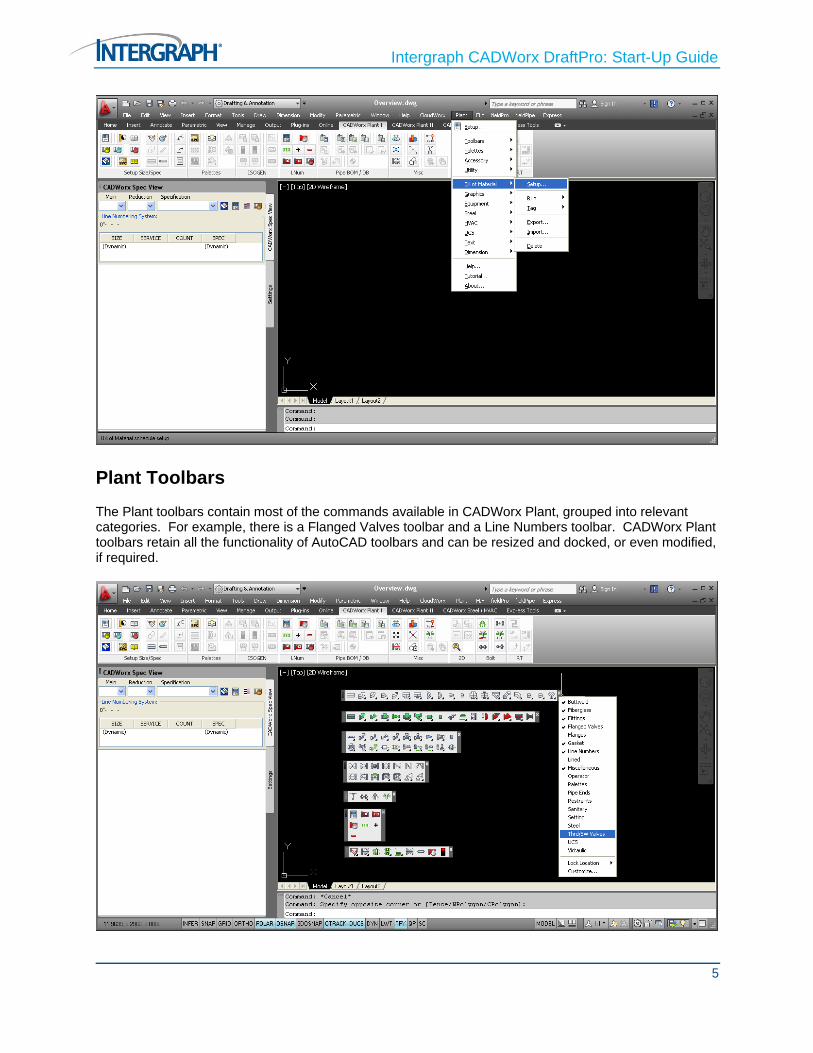
Plant Menu The Plant menu contains all of the commands available in CADWorx Plant and only those that are enabled for DraftPro will be active. In this guide, the menu options will be referred to with a “greater than” sign. For example, in the image below the option highlighted would be referred to as Plant > Bill of Material > Setup.
Intergraph CADWorx DraftPro: Start-Up Guide
5
Plant Toolbars The Plant toolbars contain most of the commands available in CADWorx Plant, grouped into relevant categories. For example, there is a Flanged Valves toolbar and a Line Numbers toolbar. CADWorx Plant toolbars retain all the functionality of AutoCAD toolbars and can be resized and docked, or even modified, if required.

Intergraph CADWorx DraftPro: Start-Up Guide
6
Command Line CADWorx DraftPro commands can be entered at the AutoCAD command line. For example, entering PIPW at the command line starts the CADWorx Pipe component.
Most of the commands are shortened aliases, which are automatically installed with CADWorx DraftPro and can be used to increase the speed of command entry. For example, the command alias, CDL, can be used instead of the full CONVERTDOUBLE command. Additional command aliases can be created by modifying the ACAD.PGP file to include the new command aliases.
CADWorx Ribbons The CADWorx DraftPro Ribbon allows you to access many commands via the Ribbon instead of using the CADWorx Plant Menu. If using this option, it is recommended that you use the SPECVIEW palette, otherwise you will need to create all components using the command line or use the CADWorx Plant toolbars as well.

Intergraph CADWorx DraftPro: Start-Up Guide
7
CADWorx Tool Palettes The CADWorx Tool Palettes allow you to access many commands via a dockable window, which can be used with, or instead of the CADWorx toolbars.
CADWorx Tool Palettes work in exactly the same way as the standard AutoCAD Tool Palettes, they can be moved, docked to the edge of the AutoCAD window, resized etc. There are also Auto-hide and Visibility options, so the Tool palettes either do not use up a lot of screen space, or are transparent, so that you can view the model behind the Tool Palette. CADWorx Tool Palettes can be edited and modified using the CUI.

Intergraph CADWorx DraftPro: Start-Up Guide
8
SPECVIEW Palette
This palette provides an alternative method to the toolbars for placing components in the model. You can also set the main and reduction sizes, the specification and the line numbering system using this palette.

Intergraph CADWorx DraftPro: Start-Up Guide
9
You can open the SPECVIEW palette with the Ribbon, by going to Plant > Palettes > SpecView Palette, or by entering SPECVIEW at the command line, or by selecting the Spec View button on the Palettes toolbar.
The Spec View tab lists all components available for the current size and specification. Any components not in the spec, or not in the current size range are not displayed. You can choose any of the available components from the list and place them into the model in the same way as using toolbars.
Drop Down Setup
After the Line numbering system is set up, the values can be altered from the SPECVIEW palette. This can be done by manually entering the value or by selecting from a drop-down list. To manually edit the line number, right-click in the category and enter the required value.
To set up the drop-down list, use the dialogue box shown below.
All available categories will be displayed in the list on the left, and values can be added into the drop-down using the utility on the right.
LINEVIEW Palette
The Line View Palette is made up of two tabs, the Line Isolate tab and the Find tab.
The Line Isolate tab allows you to isolate components based on their line number or specification. The components can be isolated alone, or alternatively the components can be partially isolated. i.e. hiding any “pipe” items which do not match the criteria specified, but keeping equipment and steel etc. visible.

Intergraph CADWorx DraftPro: Start-Up Guide
10
Isolate Options
The buttons at the top of the palette are Refresh List, Show All Components, Select Line Number by Component, Isolate Selected Line Numbers, Set Layer Options, and Help.
• Refresh List will update the list with all current Line Numbers in the model. Use this button if new Line Numbers created do not appear in the list.
• Show All Components will restore all items which have been hidden using the Isolate option.
• Select Line Number by Component allows users to pick any Pipe component in the model and will isolate all items with a matching line number.
• Isolate Selected Line Numbers will isolate all line numbers which are highlighted in the list.
• The Set Layer Options dialogue box allows you to include/exclude certain layers when the Isolate Type is set to Layer Isolate. By default, all layers are visible for line isolate. The user can exclude certain layers by selecting them in the dialogue box.
Isolate Types
There are three options you can choose from when isolating items.
1. Full will hide everything except Pipe components with the selected line number(s).
2. Partial will hide only pipe items which do not have the selected line number(s).
3. Layer will hide all non-CADWorx components based on the layer setup.

Intergraph CADWorx DraftPro: Start-Up Guide
11
Right clicking on the line number list also displays the Isolate Selected Line Numbers, Show All Components, and Refresh List options. If components have been hidden using the Line Isolate tab, these components will not be listed in the Find tab.
CADWorx DraftPro Setup Click here for video on the Setup Dialog Click here for video on Settings and Specs
Learn the various benefits of CADWorx DraftPro software and its quick and easy abilities of set up and use, so you can start designing right away.
Users will learn how they will be able to set the size and specs and also choose among a few other options such how users can draw intelligently in both double line and single line modes.
When using CADWorx DraftPro remember to always start a new drawing using the predefined templates.
Setup dialogue Box The main CADWorx DraftPro settings and variables can be modified and reviewed using the Setup dialogue box. These settings include Main Size, Reduction Size, Pipe Specification, Drawing Borders, Drawing Layers, Drawing Mode and Fitting Mode. Additionally, the settings in the Configuration file can be reviewed and modified by clicking on the Edit Config File... button.

Intergraph CADWorx DraftPro: Start-Up Guide
12
To open the Setup dialogue box, you can either select Setup from the Settings toolbar, Ribbon, go to Plant > Setup, or enter SETUP at the command line.
Clicking the check box at the bottom left of the Setup dialogue box inserts the User Name, Date and Time to the bottom left hand corner of the drawing border.
Size
To open the Sizes dialogue box, you can either select Main Size from the Setting toolbar, Ribbon, select the Size button from the Setup dialogue box, or enter SETSIZE at the command line. Additionally, you can set just the main size by entering MAIN at the command line and the reduction size by entering RED at the command line.

Intergraph CADWorx DraftPro: Start-Up Guide
13
To set the main and reduction sizes, highlight the required size and select the Main or Reduction button or double-click on the required size. The first double-click selects the main size and the second double-click selects the reduction size, further double-clicks alternate between setting the main size and the reduction size. The currently selected main size is indicated by the letter M and the reduction size by the letter R.
Specification
To open the Specification dialogue box, you can select Specification from the Setting toolbar, Ribbon, select the Specification button from the Setup dialogue box, or enter SETSPEC at the command line. Additionally, you can set the specification by entering SPEC at the command line. The SPEC command does not open the Specification dialogue box to set the specification; it prompts you to enter the name of the required specification.

Intergraph CADWorx DraftPro: Start-Up Guide
14
Double-click to select the specification required, or click it once and select the Open button. There are three types of specification, differentiated by their suffixes, as shown below.
Imperial Nominal Bore and Imperial Lengths - e.g. 150.spc
Imperial Nominal Bore and Metric Lengths - e.g. 150_M.spc
Metric Nominal Bore and Metric Lengths - e.g. 150_MM.spc
Border
To open the Drawing Borders dialogue box select the Border button from the Setup dialogue box.
You can select from a predefined drawing border, select your own drawing border or work with a simple rectangle as a drawing border. You can insert drawing borders into model space or paper space.
CADWorx components are normally inserted into model space, with drawing borders normally inserted into paper space in layout views.

Intergraph CADWorx DraftPro: Start-Up Guide
15
Drawing Scale
To open the Drawing Scale dialogue box select the Scale button from the Setup dialogue box.
You can select a drawing scale from the list on the left of the dialogue box, which will automatically set the scale (DIMSCALE), the text size (TEXTSIZE) and the LT Scale (LTSCALE), but these values can be overwritten if required, by entering values into the text boxes on the right of the dialogue box.
You can select the Measurement Format from the following four options: Architectural, Decimal, Engineering, Metric
The model should always be created at 1:1 scale with all views scaled only in paper space. The settings in this dialogue are a legacy from early version of AutoCAD, when paper space was unavailable.

Intergraph CADWorx DraftPro: Start-Up Guide
16
Setup Drawing Layers
To open the Layer Control dialogue box select the Layers button from Setup dialogue box.
In this dialogue box, you can add, rename and delete CADWorx layers. The default CADWorx layers cannot be deleted or renamed, but their line type and colours can be modified.

Intergraph CADWorx DraftPro: Start-Up Guide
17
Drawing Mode
To set the Drawing Mode, you can either select from the Setting toolbar, Ribbon, select from the Setup dialogue box, or enter the necessary command at the command line.
The following settings can be used, with the associated commands:
2D Double Line - CONVERTDOUBLE
2D Single Line – CONVERTSINGLE
Fitting Mode
To select the default fitting mode, you can either select Socket Weld or Threaded from the Setup dialogue box or select the same from the Setting toolbar or Ribbon. Setting the default fitting mode can reduce the number of prompts required when creating CADWorx components.

Intergraph CADWorx DraftPro: Start-Up Guide
18
The default fitting mode must be selected before creating the required CADWorx components and any existing components cannot be switched between Socket Weld and Threaded, and vice versa.
Configuration File
To modify this file use the Configuration File dialogue box, which is available by clicking the Edit Config File… button in the Setup dialogue box. This dialogue box enables you to modify the registry recorded configuration file. The default configuration file is C:\CADWorx DraftPro 2012\Plant\System\Imperial.cfg (or Metric.cfg for Metric use), although any number of custom configuration files can be created and restored as required.

Intergraph CADWorx DraftPro: Start-Up Guide
19
CADWorx DraftPro Line Numbers Click here for video on Line Number Overview
Learn how CADWorx DraftPro comes with ready-to-use specifications in metric and imperial formats and all reference data files of over 60,000 piping components with piping specifications that can be easily set. Learn how with the help of CADWorx DraftPro features everyone could effortlessly and intelligently start designing in 2D while saving time.
You can use CADWorx Plant with the line numbering system either enabled or disabled. When enabled, line numbers give a quick, efficient method of finding and isolating pipelines.
Line Numbering System Dialog Line Numbering System Dialog Box To open the Line Numbering System dialogue box, you can either select Line Number Setup from the Line Numbers toolbar, Ribbon, enter NUMBERSETUP at the command line, or go to Plant > Accessory > Line Numbers > Setup.

Intergraph CADWorx DraftPro: Start-Up Guide
20
You can set up line numbering systems using any of the categories from the project database. These categories may be split up using separators defined by you, for example, you could add the diameter symbol (Ø) before the nominal diameter (the short code for the diameter symbol is ALT + 0216).
Line Numbering System Options
When this switch is enabled, all components that are placed in the drawing receive a line number. There are two methods of line numbering in CADWorx, Static and Dynamic.
The Static option uses the currently selected size and spec for all future components, even if the actual size and/or spec is changed. However, you can manually modify these fields in the NUMBERSETUP dialogue box.
The Dynamic option updates the line number for new components every time you change the selected size and/or spec. When Dynamic is selected, you cannot manually change the size or spec shown in the line number for new components.
You can also manually change the line number of an existing component, or add a line number, if one was not added automatically using the Component Edit dialogue box.

Intergraph CADWorx DraftPro: Start-Up Guide
21
Annotate Line Number Options
Line Number Assign
This function allows you to assign a new line number to existing components. In Static mode, the line number will be replaced exactly as it is previewed in the setup dialogue. To use this command either click the Line Number Assign button on the Line Numbers toolbar, Ribbon, go to Plant > Accessory > Line Numbers > Assign, or enter NUMBERASSIGN at the command line.
Line Number Annotate
This function allows you to annotate pipelines with their line numbers. The text size is based upon the AutoCAD environment variable TEXTSIZE and is placed on the default text layer. You can select individual components to be annotated by selection. During the labelling process, the rubber-band line identifies which component is being labelled.
Line Number By
This function allows you to set the line number from either a P&ID project, the current drawing or by selecting a component.
Line Number Count
This function sets the current line number count value. To utilise this option, you must have the COUNT category in your current line number, you must also have your line numbering system set to Dynamic, if not, an error message will be displayed.

Intergraph CADWorx DraftPro: Start-Up Guide
22
Line Number Increment
Use this function to increment the line number count value by one.
Line Number Decrement
Use this function to decrement the line number count value by one.
Matching Component Information Options You can set system information for existing components using the options on the Setting toolbar. These options are also available on the Ribbon.
Match Component Size
To set the current main and reduction sizes from an existing component, you can either select the Size button from the Setting toolbar, Ribbon, enter COMP2SIZE at the command line, or select Plant > Utility > Set Component > Size.
If the component selected has both a main and reduction size set (e.g. reducing tee), CADWorx will allow you to reverse them, if required.
Match Component Specification
To set the current specification from an existing component, you can either select the Spec button from the Setting toolbar, Ribbon, enter COMP2SPEC at the command line, or select Plant > Utility > Set Component > Spec.

Intergraph CADWorx DraftPro: Start-Up Guide
23
Match Component Size and Specification
To set the current main and reduction sizes, and the current specification, from an existing component, you can either select the Size-Spec button from the Setting toolbar, Ribbon, enter COMP2SIZESPEC at the command line, or select Plant > Utility > Set Component > Size-Spec.
As with the Match Component Size option, CADWorx will allow you to reverse the main and reduction sizes, if required.
Match Component Line Number
To set the current line number from an existing component, you can either select the Line button from the Setting toolbar, Ribbon, enter COMP2LINE at the command line, or select Plant > Utility > Set Component > Line.
You can only use this command if your line numbering system is set to Static.
This command allows you to set the current line number by selecting a component with the required line number. Any components created after running this command will use the new line number. This command will only work if LineNumberSystem = 2 (Static).
Match Component All Settings
To set the current main size, reduction size, specification and line number you can either select the All button from the Setting toolbar, Ribbon, enter COMP2ALL at the command line, or select Plant > Utility > Set Component > All.
You can only use this command if your line numbering system is set to Static.
This command allows you to set the main size, reduction size, current specification and line number by selecting a component. Any components created after running this command will use the new line number, size and specification as the component previously selected.
This is a very efficient method of setting and modifying line numbers once a model has been started and the line numbering systems and line numbers have been established.
CADWorx DraftPro Generating Plans Click here for video on Generating Plans
Here you will learn about the 2D modeling functions in CADWorx DraftPro by generating a simple plan.
At Intergraph we understand the importance of working with existing tools available in the AutoCAD software. With CADWorx DraftPro, when it comes to inserting, selection windows, move, copy, stretch, and even mirror – You can trust that you can work as you normally work in AutoCAD and the components will understand the changes and remain intelligent.
Setup Dialog Launch CADWorx DraftPro 2012.
1. Create a new drawing using the imperial template.

Intergraph CADWorx DraftPro: Start-Up Guide
24
2. Open the Setup dialogue box.
3. Set the Drawing Mode to 2D Double Line
4. Insert a border: 11x22 (Ansi-C)
5. Set the scale to: ½”=1’
Spec View Palette 6. Set the specification to ANSI Class 150.
7. Set the main size to 4” and set the reduction size to 3”.
Line Number Setup 8. Set the Line Number using the following settings.
9. Setup the line numbering system to SIZE-SERVICE-COUNT-SPEC
10. Enable the Line numbering system (Dynamic Size/Spec)

Intergraph CADWorx DraftPro: Start-Up Guide
25
Drop Down List
11. Set the Line Numbering Drop Down Setup to the following settings.
a. SERVICE: P1, P2
b. COUNT: 1001, 1002
12. Go to the Spec View Palette
a. Select P1 for Service
b. Select 1001 for Count

Intergraph CADWorx DraftPro: Start-Up Guide
26
Generating a Drawing
We will use the CADWorx Spec View Palette to insert the following components. The drawing should resemble the one shown below. Start by inserting the following components:

Intergraph CADWorx DraftPro: Start-Up Guide
27
Vertical Line
13. 4" LONG WELD NECK, RF 150LB
a. Pick start point or [Length/Plain end] <last point>: P
b. Pick plain end point <last point>:
c. Pick direction:
14. 4" FLG, RFWN 150LB S/STD BORE, ASTM A-105
a. Pick start point or [Face end] <last point>:
b. Pick direction:
15. 4"x3" REDUCER, CONC S/STD, ASTM A-234 GR WPB
a. Pick large end point or [Small end] <last point>:
b. Pick small end direction:
16. 3" FLG, RFWN 150LB S/STD BORE, ASTM A-105
a. Pick start point or [Face end] <last point>:
b. Pick direction:
17. 3" GATE VALVE, 150LB FLG
a. Pick start point or [Center] <last point>:
b. Pick direction:
18. 3" FLG, RFWN 150LB S/STD BORE, ASTM A-105
a. Pick start point or [Face end] <last point>:
b. Pick direction:
19. 3" PIPE, S/STD SMLS, ASTM A-106 GR B:
a. Pick start point or [TOP/BOP] <last point>:
b. Pick end point: 120
20. 3" ELL, 90° LR S/STD, ASTM A-234 GR WPB:
a. Pick start point or [Corner] <last point>: C
b. Pick corner point:
c. Pick first direction:

Intergraph CADWorx DraftPro: Start-Up Guide
28
d. Pick second direction:
21. 3" PIPE, S/STD SMLS, ASTM A-106 GR B:
a. Pick start point or [TOP/BOP] <last point>:
b. Pick end point: 160
Pump Station
22. 3" TEE, STR. S/STD, ASTM A-234 GR WPB
a. Pick start point or [Branch/Center] <last point>: C
b. Pick center point:
c. Pick main end direction:
d. Pick branch end direction:
23. 3" PIPE, S/STD SMLS, ASTM A-106 GR B:
a. Pick start point or [TOP/BOP] <last point>:
b. Pick end point: 24
24. 3" ELL, 90° LR S/STD, ASTM A-234 GR WPB:
a. Pick start point or [Corner] <last point>: C
b. Pick corner point:
c. Pick first direction:
25. 3" PIPE, S/STD SMLS, ASTM A-106 GR B:
a. Pick start point or [TOP/BOP] <last point>:
b. Pick end point: 36
26. 3" FLG, RFWN 150LB S/STD BORE, ASTM A-105
a. Pick start point or [Face end] <last point>:
b. Pick direction:
27. 3" GATE VALVE, 150LB FLG
a. Pick start point or [Center] <last point>:
b. Pick direction:
28. 3" FLG, RFWN 150LB S/STD BORE, ASTM A-105

Intergraph CADWorx DraftPro: Start-Up Guide
29
a. Pick start point or [Face end] <last point>:
b. Pick direction:
29. 4"x3" REDUCER, CONC S/STD, ASTM A-234 GR WPB
a. Pick large end point or [Small end] <last point>: S
b. Pick small end point <last point>:
c. Pick large end direction:
30. 4" FLG, RFWN 150LB S/STD BORE, ASTM A-105
a. Pick start point or [Face end] <last point>:
b. Pick direction:
31. 4" LONG WELD NECK, RF 150LB
a. Pick start point or [Length/Plain end] <last point>: P
b. Pick plain end point <last point>:
c. Pick direction:
32. Use AutoCAD MIRROR command and symmetrically copy the suction pump line.
Control Set
33. Go to the Spec View Palette and set the main size to 3” and set the reduction size to 2”
34. Insert the following as fitting make-up as shown in the image:
a. 3” Flange
b. 3” Gate Valve
c. 3” Flange
d. 12” Pipe
e. DRAIN: 3 x ½” Threadolet, ½” Nipple 6” length, ½” Gate Valve and ½” Plug Change your size to 3 inch Main and ½ inch Reduction
f. 3X2 Reducer
g. 2” Flange
h. 2” Control Valve
i. 2” Flange
j. 2X3 Reducer

Intergraph CADWorx DraftPro: Start-Up Guide
30
k. 12” Pipe
l. DRAIN: 3 x ½” Threadolet, ½” Nipple 6” length, ½” Gate Valve and ½” Plug Change your size to 3 inch Main and ½ inch Reduction
m. 3” Flange
n. 3” Gate Valve
o. 3” Flange
Bypass
Insert the following as items to make up 1” the bypass line:
35. Set the main size to 3” and set the reduction size to 1”
36. Insert: 3"x1" THREDOLET, 3000LB FS, ASTM A-105
a. Pick start point <last point>: Insert the thread-o-let 24 inches from the elbow on the vertical side.
b. Pick branch end direction:
37. Insert: 3"x1" THREDOLET, 3000LB FS, ASTM A-105
a. Pick start point <last point>: Insert the thread-o-let 6 inches from the flange on the horizontal side.
b. Pick branch end direction:

Intergraph CADWorx DraftPro: Start-Up Guide
31
38. Right click on the PIPE and select THREADED
a. Draw Threaded pipe so that it intersects with the other Thread-o-let as shown below
39. Add an elbow, corner first to connect the 2 threaded pipes.
40. Insert a Globe valve by Center so that it is aligned to the control valve as shown below:

Intergraph CADWorx DraftPro: Start-Up Guide
32
CADWorx DraftPro Double line to Single line Click here for video
CADWorx DraftPro retains the functionality that exists today in AutoCAD. In DraftPro with an ease of use concept you can choose to change your components from a double line representation to a single representation throughout your design, as shown in this video.
It is important for users to be able to model in either a 2D or single line mode. In this section a piping model will be produced in both 2D double line and single line modes. This image illustrates the 2D double line bypass before the change.
Convert from 2D Double Line to 2D Single Line 2D Single Line mode is typically used for drawing drains and vents on 2D drawings. In the following example we will convert a bypass loop to 2D Single Line; this should look as shown below when completed.

Intergraph CADWorx DraftPro: Start-Up Guide
33
1. Go to the Ribbon and select 2D Single Line and select the bypass and the 2 drains and ENTER
CADWorx DraftPro Bill of Material Click here for video
CADWorx DraftPro generating a Bill of Material is automatic and you can save time. Generating a bill of material manually - could be very time consuming. Here you can quickly choose what information you want displayed in the report. And to show you just how easy you can customize the Bill of Material – you will add WEIGHT - so that this specific information is also included in the report.

Intergraph CADWorx DraftPro: Start-Up Guide
34
The Bill of Material that will be generated on the drawing can be also exported to popular external file formats. This export command allows users to export to: Access, Excel, a Text file or HTML formats. By using CADWorx DraftPro users are now able to leverage AutoCAD by using free productivity tools offered such as this BOM Report and BOM Export commands.
1. Select the Bill of Material Setup from the Ribbon and add WEIGHT
2. Go to Plant>Bill of Material>Tag>Toggle, this will turn off the automatic tagging that is on by default. Later we will review how to tag individually.
3. Select BOMCUT from the ribbon and follow the command line.
Your BOM report should look like below.
Intergraph CADWorx DraftPro: Start-Up Guide
35
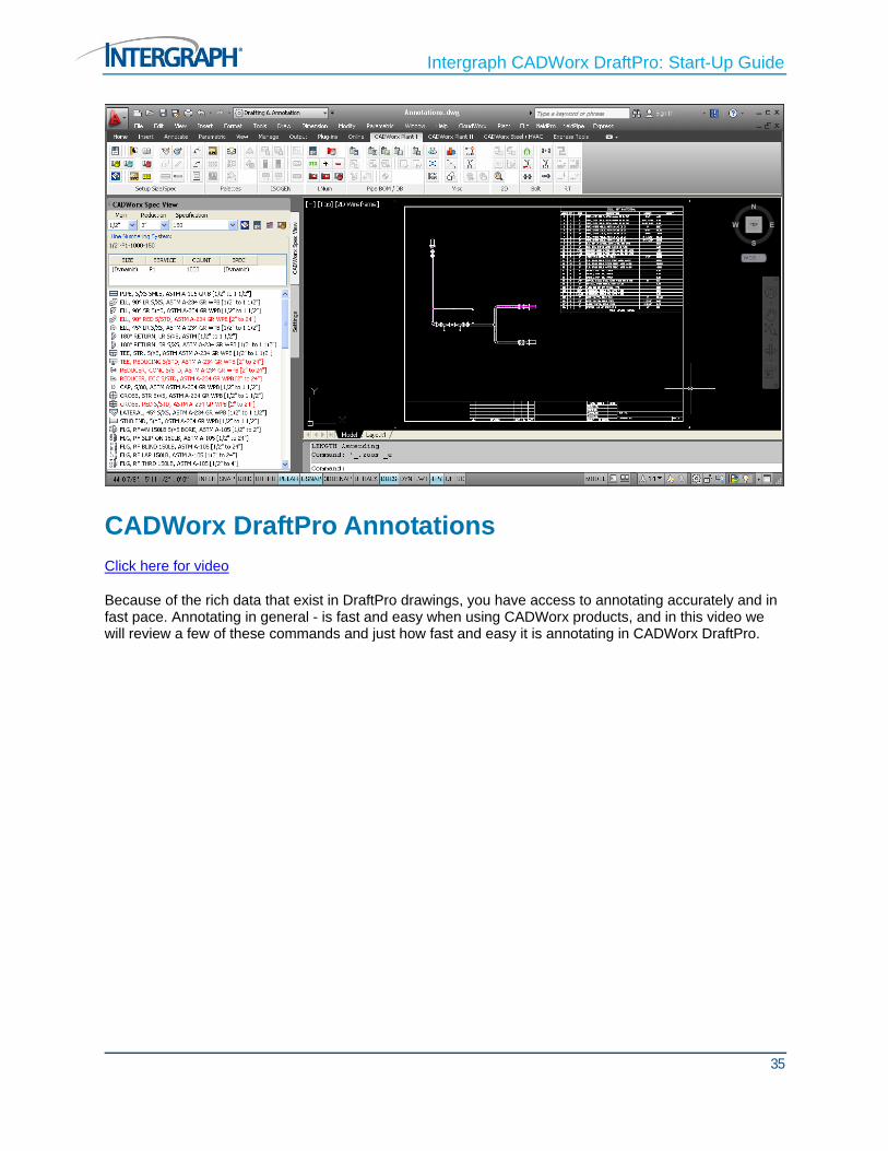
CADWorx DraftPro Annotations Click here for video
Because of the rich data that exist in DraftPro drawings, you have access to annotating accurately and in fast pace. Annotating in general - is fast and easy when using CADWorx products, and in this video we will review a few of these commands and just how fast and easy it is annotating in CADWorx DraftPro.

Intergraph CADWorx DraftPro: Start-Up Guide
36
BOM Tagging
Bill of Material tags can be toggled ON or OFF when generating a report. By default they are turn on. When you generate a report you have the option to select Manual Placement or Automatic placement.
When the Bill of Material tags are turned off you can insert the tags individually by accessing the menu:

Intergraph CADWorx DraftPro: Start-Up Guide
37
Dimension Automatic There is many way to dimension your CADWorx DraftPro drawing. You can automatically dimension your drawing (this is possible only in the MODEL SPACE) by using the AUTODIM command:
1. Select Automatic Dimension from the Ribbon
2. Enter an option [Flange/Offset/Selection] Flange
3. Flange dimensioning [ON/Off] <Off>: ON
4. Enter an option [Flange/Offset/Selection] <Selection>: O
5. Enter offset distance: Specify second point:
6. Enter an option [Flange/Offset/Selection] <Selection>: S
7. Select the objects to dimension. Press ENTER when you are finished.
8. Pick centroid point of dimensions.
Select the centroid for the dimensions. For example, if you selected two pieces of parallel pipe with elbows attached to each end to dimension, and then selected a point between the two pieces of pipe, the software would place the dimension lines to the outside. You can also use the dimension that are available in AutoCAD.
Line Number Annotate This function allows you to annotate pipelines with their line numbers. The text size is based upon the AutoCAD environment variable TEXTSIZE and is placed on the default text layer. You can select

Intergraph CADWorx DraftPro: Start-Up Guide
38
individual components to be annotated by selection. During the labelling process, the rubber-band line identifies which component is being labelled. See below:
This command extracts the line number that was setup in the Spec View Palette and Line Number Setup Dialog. The line number that is setup to start the drawing is stored with every CADWorx component.
Select Line Number Annotate from the Ribbon.
1. Select the components to annotate.
2. Start point or [Leader/Justify].
3. Select the point for the annotation.
4. Rotation angle <0>.
5. Select the direction for the annotation, or type the angle for the annotation on the command line and press ENTER.

Intergraph CADWorx DraftPro: Start-Up Guide
39
Component Annotate
1. Select annotate Component command from Ribbon. Annotate the valve with the leader option.
2. Annotation type [Short/Long/Tag] <Short> S
3. Select component to annotate description: Select the valve

Intergraph CADWorx DraftPro: Start-Up Guide
40
4. Start point or [Leader/Justify] Leader
5. Specify next point
Operators
Pick center of valve - Select a point.
Enter actuator, or hand wheel, outside diameter on the command line, and press ENTER.
CADWorx DraftPro Sections and Plans Click here for video
With simple commands - Intergraph CADWorx DraftPro can quickly and accurately give you a complete bill of material. Designers can easily go from a plan, to an elevation and back to plan. With these simple steps you can have a truly accurate model and bill of material. Let’s review 2 simple steps that take you through this process.
Change Elevation This command must be accomplished in the Plan view / UCS world. All components must be drawn at the necessary elevation before using Plan to Elevation. If the plans are created with the UCS left at a 0' elevation, the elevation shows all components at the same elevation. Use the Change command from the PL/EL panel on the CADWorx Plant II tab to change the elevation as needed.

Intergraph CADWorx DraftPro: Start-Up Guide
41
When you use the Change command you are prompted some of the following options..
Arbitrary Places the component anywhere in the drawing.
BOP Correction Aligns the pipe bottom with the center of the connected piece.
This command moves all selected entities (blocks, lines, polylines and so on) to a new elevation in reference with the world coordinate system. You can also change a component elevation to 1/2 it’s actual outside diameter
1st Step: Plan to Elevation The first step is getting your model from plan to elevation. In DraftPro you can choose from a North, South, West or East elevation. Changes the selected model to 2d, and changes to a north view. See the image below.

Intergraph CADWorx DraftPro: Start-Up Guide
42
When you use Plan to Elevation command you are prompted some of the following options:
Component information [ON/Off] <Off> Leaves or removes the component information in the drawing. If the plan is used for Bill of Material generation, the component information should be off. If the elevation is to be placed back in the plan, type ON.
Draw pipe end baseballs [Yes/No] <No> Indicates whether pipe end baseballs are placed on the drawing.
Delete selection for future replacement [Yes/No] <No> Deletes the original component from the drawing. Use this option when you are deleting the plan and replacing it with Elevation to Plan. With this option, you can make an elevation, delete the plan, make modifications to the elevation, and then place it back into the plan.
Pick base point - Places the component view within the drawing.
Plan to Elevation: East
For this example you will open an existing drawing and use the Plant to Elevation EAST. Once the elevation is created then the missing components can be drawn.
1. Open Plan to Elevation drawing
2. Click EAST on the Ribbon
3. Select objects the following components.

Intergraph CADWorx DraftPro: Start-Up Guide
43
4. For the reference point pick the center point of the end of pipe as shown below:
5. Component information [ON/Off] <Off>: ON
6. Draw pipe end baseballs [Yes/No] <No>: N
7. Delete selection for future replacement [Yes/No] <No>: Y This deletes the original component you selected from the drawing.

Intergraph CADWorx DraftPro: Start-Up Guide
44
8. Pick base point for elevation: Select a point in the drawing for your base point. Place the elevation as shown below:
A copy of your model has been created and has been inserted in the drawing in EAST view. The next step is filling in what components are missing in this view. Insert the following components as shown below this will make the bypass in elevation.

Intergraph CADWorx DraftPro: Start-Up Guide
45
Control Set
41. Go to the Spec View Palette and set the main size to 3” and set the reduction size to 2”
42. Insert the following as fitting make-up as shown in the image:
a. 3” Flange
b. 3” Gate Valve
c. 3” Flange
d. 12” Pipe
e. DRAIN: 3 x ½” Threadolet, ½” Nipple 6” length, ½” Gate Valve and ½” Plug Change your size to 3 inch Main and ½ inch Reduction
f. 3X2 Reducer
g. 2” Flange
h. 2” Control Valve
i. 2” Flange
j. 2X3 Reducer
k. 12” Pipe
l. DRAIN: 3 x ½” Threadolet, ½” Nipple 6” length, ½” Gate Valve and ½” Plug Change your size to 3 inch Main and ½ inch Reduction

Intergraph CADWorx DraftPro: Start-Up Guide
46
m. 3” Flange
n. 3” Gate Valve
o. 3” Flange
Bypass
Insert the following as items to make up 1” the bypass line:
43. Set the main size to 3” and set the reduction size to 1”
44. Insert: 3"x1" THREDOLET, 3000LB FS, ASTM A-105
a. Pick start point <last point>: Insert the thread-o-let 24 inches from the elbow on the vertical side.
b. Pick branch end direction:
45. Insert: 3"x1" THREDOLET, 3000LB FS, ASTM A-105
a. Pick start point <last point>: Insert the thread-o-let 6 inches from the flange on the horizontal side.
b. Pick branch end direction:
46. Right click on the PIPE and select THREADED
a. Draw Threaded pipe so that it intersects with the other Thread-o-let as shown below
47. Add an elbow, corner first to connect the 2 threaded pipes.

Intergraph CADWorx DraftPro: Start-Up Guide
47
48. Insert a Globe valve by Center so that it is aligned to the control valve as shown below:
2nd Step: Elevation to Plan The second step is just as simple. To start select the command to goes from elevation to plan. Here select all the components that were drawn in elevation. This function makes a copy of the components

Intergraph CADWorx DraftPro: Start-Up Guide
48
and converts it automatically to a plan representation. All while retaining the intelligence of the DraftPro model.
When you use Plan to Elevation command you are prompted some of the following options:
Component information [ON/Off] <Off> Leaves or removes the component information in the new drawing.
Draw pipe end baseballs [Yes/No] <No> Indicates whether places pipe end baseballs are placed on the new drawing.
Delete selection for future replacement [Yes/No] <No> Deletes the original component from the drawing.
Pick base point and rotation Specifies the location and direction of the component view within the drawing.
Using this option allows for either a north, south, east or west elevation to be viewed in plan view based on the rotation you chose when placing the component. Use this option when an elevation has been changed and you want to place it back into a plan.
Elevation to Plan
For this example you will open an existing drawing and use the Plant to Elevation EAST. Once the elevation is created then the missing components can be drawn.
1. Open Elevation to Plan drawing
2. Click the command Elevation to Plan on the Ribbon

Intergraph CADWorx DraftPro: Start-Up Guide
49
3. Select objects the following components.
4. Component information [ON/Off] <Off>: ON
5. Draw pipe end baseballs [Yes/No] <No>: N
6. Delete selection for future replacement [Yes/No] <No>: N

Intergraph CADWorx DraftPro: Start-Up Guide
50
7. Pick reference point: For the reference point pick the center point of the end of pipe as shown below:
8. Pick base point and rotation:
9. Make sure your orient the new piping the correct direction. See below:

Intergraph CADWorx DraftPro: Start-Up Guide
51
This will place your control station back into plan. Remember just by doing these simple steps you now have access to a truly accurate model and bill of material.
Spec editor Click here for video
Learn how the CADWorx specs provided can be used as an example to get you quickly started creating your own specs. All spec changes you make are all usable with CADWorx Plant Professional and the interface is the exact same interface. So when you are ready to move to 3d you can take your work with you. Use CADWorx DraftPro and enjoy – for the first time a FREE, easy, open
1. Click the Start Spec Editor command found on the Spec View Palette

Intergraph CADWorx DraftPro: Start-Up Guide
52
2. Click the Save As… button and save the 150LB spec as Intergraph.spc
3. Go to the Component list and add Valves, Gate
4. Define the item as Gate Valve Buttweld/Flanged

Intergraph CADWorx DraftPro: Start-Up Guide
53
5. Go to the Data File section and Select data file GAT_F.300
6. In the Details section, check on Optional Component
7. For Sizes, set the Start size to 6 and End size to 6 Setting the sizes to 6 will restrict this optional component to only 6 inches
8. In the Long Description field replace the word Crane with Fisher.

Intergraph CADWorx DraftPro: Start-Up Guide
54
9. Click OK, Save and Exit.
When you return to your Spec View Palette you will have seen the new item in your list.
All spec changes you make are all usable with CADWorx Plant Professional and the interface is the exact same interface. So when you are ready to move to 3d you can take your work with you. Use CADWorx DraftPro and enjoy – for the first time a FREE easy, open and scalable solution.

Intergraph CADWorx DraftPro: Start-Up Guide
55