drainage control and mine dewatering at faro open pit mine · drainage control and mine dewatering...
TRANSCRIPT
SECTION2 Drainage Control for Surface Mines
10 Drainage Control and Mine Dewatering
at Faro Open Pit Mine
ABSTRACT
by Randy S. Lopaschuk, Geological/Geotechnical Engineer, Cyprus Anvil Mining Corporation,
Faro, Yukon Territory, Canada
There have been many problems associated with drainage control and mine dewatering since mining started at the Faro open pit mine. Drainage and dewatering programs have been mainly implemented in three areas of the mine: the Faro Creek diversion ditch outside of the pit limits, the Faro Valley, and the bottom of the open pit. These programs utilize a system of ditches, pipelines, sumps, pumps and inclined drainholes. This paper describes the application of these methods of dealing with water problems at the mine.
INTRODUCTION
Cyprus Anvil Mining Corporation operates an open pit lead-zinc-silver mine and a 10,000 tons per day concentrator at Faro, Yukon Territory, Canada. Since mining began in 1968 there have been problems associated with drainage control and mine dewatering and these problems have increased as the open pit has expanded and deepened. This paper discusses the problems encountered and the solutions that have been applied to enable effective mining operations to continue.
DRAINAGE CONTROL & DEWATERING AT FARO OPEN PIT MINE 233
Miles IOO
~ O Kilorne1eJ50
I WHITEHORSE
· .. f'. ,_ ... 1ld' l .. - .. YUK~H- •
e.c. 130°
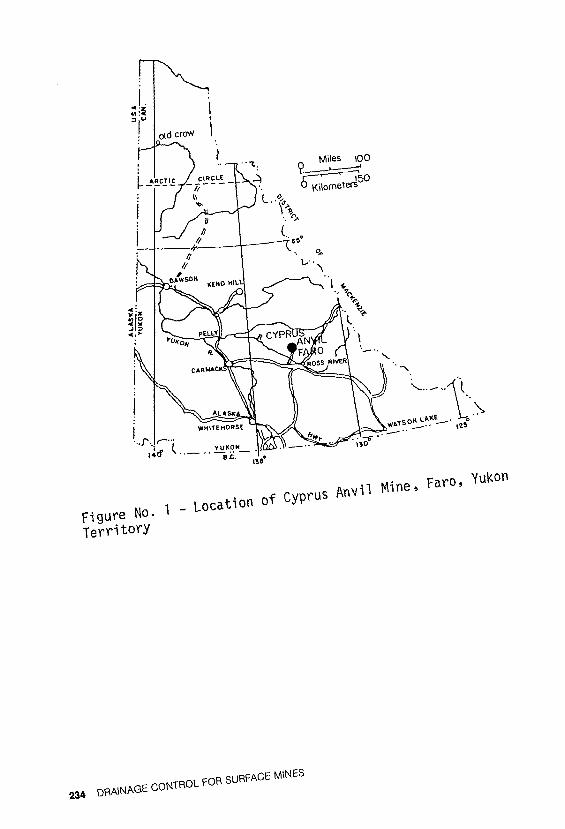
Figure No. 1 - Location of Cyprus Anvi1 Mine, Faro, Yukon
Territory
234 DRAINAGE CONTROL FOR SURFACE MINES
Location and Climate
The Faro orebody, approximately 120 air miles northeast of Whitehorse, is located east of Rose Mountain and northeast of Mount Mye in the Anvil Range in the east central Yukon (see Figure No. 1).
Temperatures at the minesite range from minus fifty degrees Fahrenheit at mid-winter minimum to plus eighty-five degrees Fahrenheit at summer maximum. Freezing conditions persist from mid-September until early May. Snowfall accounts for one-half of the mean annual precipitation of 15 inches and the maximum snowfall cover ranges up to fifty inches in late March.
Geology
The Faro deposits consist of three nearly horizontal, strataform, stratabound, massive pyritic lead-zinc sulfide zones. Zones 1 and 3 are separate parts of the Large Faro deposit vertically offset by faulting and related intrusions, while the Small Faro deposit (Zone 2) forms a completely separate unit.
The Large Faro deposit is the present area of concern regarding mine dewatering as Zone 2 has not yet been developed. This deposit is lenticular in plan and crosssection with a 5,000 foot length, 1 ,600 foot width and 150 foot average thickness. Zone 1 is overlain by 90 feet of overburden and 100 to 160 feet of waste rock, while Zone 3 is overlain by 100 feet of overburden and approximately 400 feet of waste rock.
The Faro sulfide bodies are stratabound successively by a thin quartzite which is in sharp contact with "bleached" muscovite schists which grade outward into normal biotitemuscovite + andalusite schists with irregular interbands of graphite. -The schists are overlain conformably by blocky, green calc-silicate phyllites. The dominant foliation in the schists and phyllites, dipping approximately 20 degrees to the southwest, is roughly parallel to the lithological contacts.
The deposits have been intruded by post-ore dykes associated with the Anvil batholith. At the northwest end, sulfides abut against white, heavily altered, medium-grained quartz monzonite. The fault separating Zones 1 and 3 has
DRAINAGE CONTROL & DEWATERING AT FARO OPEN PIT MINE 235
been intruded by a hornblende-biotite diorite dyke swarm.
PROBLEMS RELATED TO WATER IN THE PIT
Water presently flows into the pit from the Faro Creek valley and from groundwater seepage at the rate of approximately 400 U.S. GPM. Undesirable pit operating and design conditions, as well as other problems, resulting from this incoming water are:
In the Mine
l) Saturation of the east wall of the pit, resulting in unstable slopes and decreased slope design angles, necessitating additional stripping requirements.
2) Excessive slurry consumption because of extensive wet blast hole loading conditions. It costs twice as much to load a wet hole with the appropriate explosive as it does to load a dry hole. Also redrilling is often necessary because the wet holes cave fairly quickly.
3) Water glaciates across haul roads in the pit bottom in the winter, necessitating constant maintenance and resulting in slippery roads with frequent chuckholes. During spring thaw, this ice buildup turns to deep mud. These roadway conditions result in increased maintenance and downtime on haulage equipment.
4) The water flow necessitates construction and maintenance of ditches along pit ramps. Ice and debris accumulation around these ditches frequently widens the ditch area such that it produces single lane traffic on ramps, thereby increasing truck cycle times and lowering productivity.
5) In the winter, frozen material build-ups occur in truck boxes and in shovel buckets. This causes extra expense due to longer loading times and smaller than normal truck loads.
In the Mi 11
l) If the ore is very wet, it may be necessary to stockpile it before crushing in order that it will dry. If the ore is stockpiled for too long, oxidation
236 DRAINAGE CONTROL FOR SURFACE MINES
occurs which creates problems in the concentration process.
2) Sloppy wet ore spills off conveyors, blocks screens and chutes, quickly blocks return rollers and causes overall cleanup problems.
3) In the winter, ice in the ore causes problems in the coarse and fine ore bins.
These problems can be greatly reduced if proper drainage control and dewatering methods are used to cut down the flow and accumulation of water in the pit. Increased safety of the pit slopes and cost savings in operations will result from a comprehensive mine dewatering program. Because of these reasons, Cyprus Anvil reassessed its dewatering programs with the aid of consultants in 1975 and improved and added to them for future improvements in pit water control.
HISTORY OF DEWATERING
The Faro orebody lies with its long axis approximately perpendicular to the Faro Creek valley. Initial mining in the upper part of the orebody took place on the northwest slope of the valley. While mining was confined to this slope, water was not a major factor as it could be conveyed by ditches down the slope to Faro Creek.
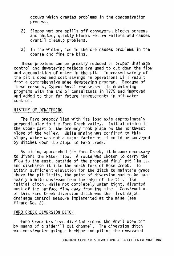
As mining approached the Faro Creek, it became necessary to divert the water flow. A route was chosen to carry the flow to the east, outside of the proposed final pit limits, and discharge it into the north fork of Rose Creek. To attain sufficient elevation for the ditch to maintain grade above the pit limits, the point of diversion had to be made nearly a mile upstream from the edge of the pit. The initial ditch, while not completely water tight, diverted most of the surface flow away from the mine. Construction of this Faro Creek diversion ditch was the first major drainage control measure implemented at the mine (see Figure No. 2).
FARO CREEK DIVERSION DITCH
·Faro Creek has been diverted around the Anvil open pit by means of a sidehill cut channel. The diversion ditch was constructed using a backhoe and piling the excavated
DRAINAGE CONTROL & DEWATERING AT FARO OPEN PIT MINE 237
/
SCALE· I":: 850'
FARO / VALLEY /
""()LO FARO / CREEK BED
/ ,/
// /I I
• • ,,
i
,1 1' I ,,
11 JI Jf 1' ,1 II
,, ) ------/-
~/
1 / /I
I I I I f I FARO CREEK 1 I DIVERSION 1' DITCH
I // ,,
I/ ,, ,, ,, ,, ,1 1 / 11 ,,
11 1, 11 IJ 11 11 Ii II \I ,1 ,,
I \ 1 TO NORTH \~ FORK OF
14,. ROSE CREEK
Figure No. 2 - Open pit plan showing components of mine dewatering system
238 DRAINAGE CONTROL FOR SURFACE MINES
silty soil as a low dyke on the downhill side of the ditch. A rockfill dyke was later constructed along the downhill side of the diversion ditch adjacent to the soil dyke, increasing the height of the dyke. During the spring runoff, the water flow in the diversion ditch rose above the portion of the ditch confined by silty soil, and flowed against the adjoining rockfill dyke causing significant leakage. The ditch was mainly excavated in silty sand containing gravel, cobbles and small boulders. The silt content is sufficiently high to provide a relatively impervious seal, but the ditch does leak to some extent. However, the Faro Creek diversion ditch does not provide a significant portion of the groundwater seepage entering the pit. (1)
Initially, the diversion ditch simply discharged down a hillside after it was past the ultimate pit limits. The outflow cut its own series of channels down the hillside to connect with Rose Creek. This outflow area eventually became responsible for three problems:
1) Heavy, erratic erosion of the hillside.
2) Formation of a large alluvial fan in Rose Creek.
3) Higher than normal suspended solids in Rose Creek.
The construction of a channel with favourable gradients, alignment, cross-sectional configuration and outflow conditions between the existing outflow of Faro Creek diversion ditch and Rose Creek was necessary to prevent further excess erosion and siltation in that area. The new channel alignment was selected based on the following merits:
1) Flows will be carried a safe distance from existing dumps.
2) The channel will have the maximum amount of bedrock exposure.
3) Gradients will be minimized to prevent excess erosion and subsequent siltation of Rose Creek.
4) The channel will discharge into a large, flat settling area, causing decrease in flow velocity and subsequent settling out of suspended solids prior to entry into Rose Creek.
DRAINAGE CONTROL & DEWATERING AT FARO OPEN PIT MINE 239

The channel was designed to accommodate flows from a 20 year flood, or 200 cubic feet per second.
The Relocation of the Faro Creek Diversion Ditch
A decision was made in 1978 to extend the final pit limits of the northeast corner and east wall of the pit for slope stability and ore recovery reasons. The establishment of new ultimate pit limits meant that a portion of the existing Faro Valley diversion ditch would have been too close to, or within, these pit limits. Therefore, it was necessary to relocate this section of the ditch. The ditch had to be relocated back into a hillside and a deep cut had to be made to keep the new section on grade with the remaining old sections of the ditch. The relocation route was 2,000 feet long with a 0.9% grade and designed cut slopes of 1 .5:1 dropping to a 12 foot horizontal bottom. Bulldozers and scrapers were used to construct the ditch and 100,000 cubic yards of glacial till and rock were removed.
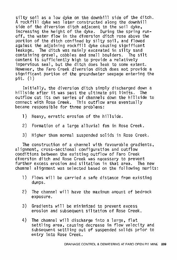
The ditch was constructed almost completely in sands and gravels, except for a 400 foot section where bedrock was encountered along the base of the ditch. The ditch was very permeable and it was thought that too much water would seep out of the ditch and eventually end up in the pit through subsurface flow. To rectify this, it was decided to cut the ditch one foot below grade and then add a silty, clayey fill to provide a more impermeable bottom. The fill was then compacted with a self-propelled, smooth drum compactor. However, leakage from the ditch still presented a big problem because water was escaping along the overburden/bedrock contact in the section of the ditch that had encountered bedrock. This water was entering the pit along the exposed overburden/bedrock contact and eventually interfering with mining operations and causing wet blastholes on the east wall of the pit.
To prevent this water from entering the pit, it was decided to line 600 feet of the diversion ditch along the section where the water was escaping. A 32 foot wide, flexible, three-ply, reinforced, 30-MIL, polyethylene liner was installed to stop the leakage.
GROUNDWATER DRAINAGE OF THE FARO VALLEY
Problem
240 DRAINAGE CONTROL FOR SURFACE MINES
I I
t
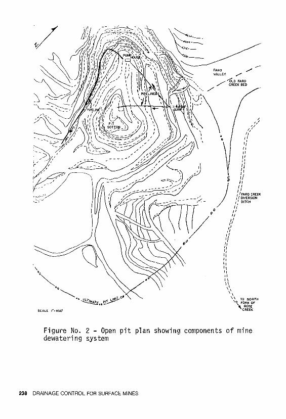
Figure No. 2A - Part of the relocated Faro Creek Diversion Ditch cut into the hillside above the pit.
Figure No. 2B - Water entering bedrock contact.
overburden/
DRAINAGE CONTROL & DEWATERING AT FARO OPEN PIT MINE 241
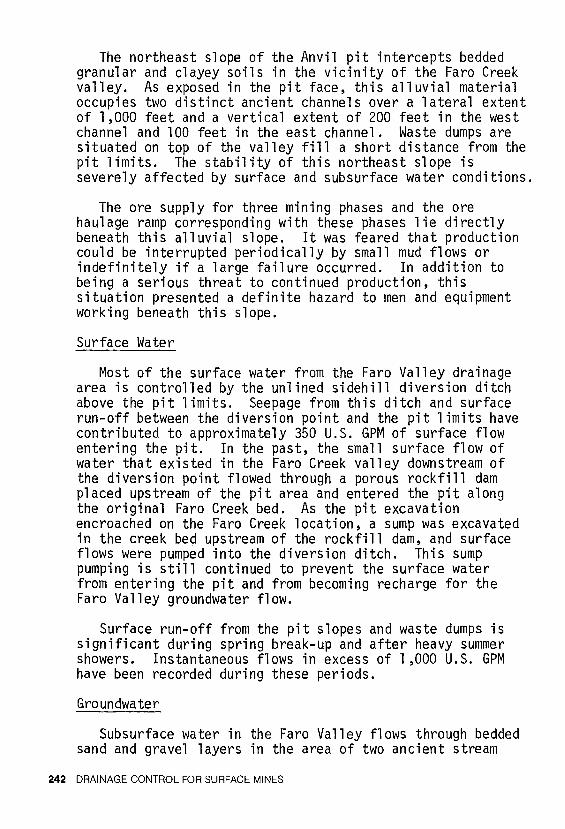
The northeast slope of the Anvil pit intercepts bedded granular and clayey soils in the vicinity of the Faro Creek valley. As exposed in the pit face, this alluvial material occupies two distinct ancient channels over a lateral extent of 1,000 feet and a vertical extent of 200 feet in the west channel and 100 feet in the east channel. Waste dumps are situated on top of the valley fill a short distance from the pit limits. The stability of this northeast slope is severely affected by surface and subsurface water conditions.
The ore supply for three mining phases and the ore haulage ramp corresponding with these phases lie directly beneath this alluvial slope. It was feared that production could be interrupted periodically by small mud flows or indefinitely if a large failure occurred. In addition to being a serious threat to continued production, this situation presented a definite hazard to men and equipment working beneath this slope.
Surface Water
Most of the surface water from the Faro Valley drainage area is controlled by the unlined sidehill diversion ditch above the pit limits. Seepage from this ditch and surface run-off between the diversion point and the pit limits have contributed to approximately 350 U.S. GPM of surface flow entering the pit. In the past, the small surface flow of water that existed in the Faro Creek valley downstream of the diversion point flowed through a porous rockfill dam placed upstream of the pit area and entered the pit along the original Faro Creek bed. As the pit excavation encroached on the Faro Creek location, a sump was excavated in the creek bed upstream of the rockfill dam, and surface flows were pumped into the diversion ditch. This sump pumping is still continued to prevent the surface water from entering the pit and from becoming recharge for the Faro Valley groundwater flow.
Surface run-off from the pit slopes and waste dumps is significant during spring break-up and after heavy summer showers. Instantaneous flows in excess of 1 ,000 U.S. GPM have been recorded during these periods.
Groundwater
Subsurface water in the Faro Valley flows through bedded sand and gravel layers in the area of two ancient stream
242 DRAINAGE CONTROL FOR SURFACE MINES
channels and collects in a ditch at the 4030 elevation. This ditch was constructed along a wide bench approximately half way down the pit wall. Initially, the ditch was unlined, but because of excessive leakage, it was later lined with a three foot diameter, half-circular metal flume.
At the pit face, the main groundwater flow is between the bedrock/overburden contact and the 4110 elevation with smaller flows stratified above impermeable silt and clay layers upwards to the 4170 elevation in the west channel and the 4115 elevation in the east channel. Accumulated subsurface flows in excess of 350 U.S. GPM have been measured in weirs in the 4030 ditch.
During November and December, 1975 and January, 1976, five rotary test holes were drilled through the waste dumps and overburden into bedrock to determine soil density and internal stratigraphy. Multiple piezometer installations were located in these holes to determine groundwater conditions and to monitor the effectiveness of a proposed dewatering system.
From the borehole investigations, the alluvium appeared to be mainly bedded gravels and sands with varying amounts of silt. Zones of varved clay and clayey sand-gravel occur but cannot be readily projected from hole to hole. A "marker bed" of white granitic gravel indicated an apparent bedding dip of 10 degrees toward the pit. The bedrock surface dips at 2 to 5 degrees toward the pit. (2)
The piezometer readings indicated a groundwater flow within the alluvium channels along the alluvium/bedrock contact to a depth of 50 to 80 feet with a gradient of 6 to 9 degrees toward the pit. There appeared to be no general perched water table except locally near the present creek bed. The springs observed at the face above the 4115 elevation were presumed, therefore, to be small, isolated flows not connected with the main piezometric surface. The piping observed at the bedrock/overburden contact indicates that the piezometric surface steepens as it approaches the pit.
Slope Stability
Numerous slump failures have occurred in the Faro Valley overburden slopes. On August 14, 1975 an estimated 25,000 BCV of saturated mud flowed out of the area, isolating a 15 cubic yard electric mining shovel for almost two days
DRAINAGE CONTROL & DEWATERING AT FARO OPEN PIT MINE 243
and disrupting ore development as the mud flowed into the pit bottom.
The concern was that the surface run-off could initiate large scale failures by two mechanisms. Sloughed material and mud flows could cause blockage of the groundwater outflows, thereby increasing the piezometric head to the point of instability. Also, continued sloughing could eventually cause the waste dumps and possibly the Faro Creek diversion ditch to be undercut.
The failure mechanism, due to excessive groundwater, appeared to be undermining by piping in granular soils, followed by collapse of overlying silty and clayey soils. These initial block failures, by removing weight from the passive block, by steeping the slope, and possibly by obstructing groundwater outflow, could initiate large scale (1-3 million BCV) wedge-type failures. (2)
With the groundwater level that was present in 1975, the entire slope had a very marginal factor of safety. A 20 foot increase in the piezometric head, or continued block failures, would have surely precipitated a large failure.
Solution
A long term solution to this problem was required due to the magnitude and seriousness of the situation. Four possible alternatives for stabilizing the slope were investigated:
1) Flatten the slope and remove weight from the active block by mining the waste dumps from the valley floor.
2) Intercept the groundwater before it reaches the pit face by installing inclined drain holes.
3) Install a screen of vertical well points behind the pit crest to intercept groundwater.
4) Place a sand and gravel filter blanket across the exposed sediments to control groundwater.
Solution I
Flattening the slope would have involved the removal of approximately 500,000 BCV of waste dumps from a zone 600
244 DRAINAGE CONTROL FOR SURFACE MINES

feet wide behind the pit crest. This would not have improved the stability of the blocks which were being undermined by piping, but the probability and seriousness of a large scale wedge failure would have been reduced. Failures of a magnitude similar to the August 14th. slide could still occur.
Solution II
Inclined, self-draining holes with slotted casing could be used to intercept groundwater behind the excavated pit slope, thereby preventing piping and subsequent block collapse. The holes would be collared in bedrock on the 4030 bench and driven 500-600 feet into the basal sands and gravels along the bedrock contact. Five or six holes would be drilled into each channel from locations on either side of the channel.
The advantages of inclined drains are:
1) Maximum penetration of water-bearing strata.
2) Effectiveness would not be seriously affected by sma 11 failures.
3) The system would be virtually maintenance-free.
Solution I II
A screen of vertical wells would be installed behind the pit limit to intercept the groundwater flow. The system would have the following characteristics:
1 ) Number of Wells -
2) Spacing -
3) Finished Diameter -
4) Depth per Wel 1
5) Screen Length per Well
6) Pumps -
10
100 feet
8 inches
200 feet
- 20 feet
10 H.P. submersible, 100 U.S. GPM discharge
The major disadvantages of a vertical well screen are:
DRAINAGE CONTROL & DEWATERING AT FARO OPEN PIT MINE 245

1) In case of a partial slope failure, one or more of the wells may be destroyed.
2) Due to the irregular bedrock and associated groundwater profile, it would be difficult locating wells for maximum dewatering efficiency.
3) High operational and maintenance costs are anticipated to ensure reliable and continuous operation during cold weather.
4) Minimum (vertical) penetration of water-bearing strata.
Solution IV
The forces of water seepage at cut slopes can be controlled by filter blankets. This would require a properly graded, 10 foot thick, sand and gravel filter sheet, lain against a properly trimmed slope with an additional 10 foot thickness of suitable rip-rap to serve as a stabilizing buttress and insulation blanket. The filter prevents piping while allowing the slope to drain freely.
The disadvantages of this solution are:
1) The lack of suitable equipment access to the slope.
2) The necessity of placing the filter and buttress material on the trimmed slope before any slumping occurs.
3) The source of suitable filter material.
4) The difficulty of placing the filter material on a 350 foot long, 30 degree slope.
Waste dump material could not be crushed and screened for the filter, nor could it be used as rip-rap due to its high clay content and weathered condition.
An evaluation of the four alternative solutions indicated that a system of inclined drains was the most effective and economic method of preventing large scale slope failures in the Faro Valley alluvium.
THE INSTALLATION OF DRAINHOLES IN THE FARO VALLEY
246 DRAINAGE CONTROL FOR SURFACE MINES
After the locations were chosen for the drainholes, the following aspects were considered pertaining to their installation as suggested by the consultants on the project, Piteau & Associates. (3)
l) Inclined drains should be collared in stable areas where it is unlikely that either sloughing or complete slope failure could occur and cut off the drains.
2) The inclined drains should be orientated in such a way that at least 50 feet of rock is penetrated before encountering overburden.
3) The inclined drains should be orientated or inclined in such a way that the drains do not come within about 15 feet of daylighting at any point along the drain.
The drilling of the inclined drains was performed utilizing an Aardvark Model 125 track mounted drilling machine. Six thousand feet of drilling was carried out, distributed among ten holes of approximately equal length.
Some site observations were attempted while the drilling was in progress to obtain a more complete picture of the internal stratigraphy of Faro Valley. It was difficult to determine the exact location of the overburden/bedrock contact while drilling because of the schistose or weathered nature of the bedrock in the area of the contact and because the drill cuttings were usually ground very fine, making them difficult to identify. Correlating the drilling rate with changes in soil and rock type was not particularly successful and it was also difficult to obtain accurate flow measurements during drilling because water was sometimes used while drilling. However, areas where the rate of flow suddenly increased were evident.
After each inclined borehole was drilled, it was lined with 1 .5 inch 0.0. slotted plastic pipe (the first ten feet of pipe at the collar of the hole was not slotted).
Analysis of Data
After all the inclined drainholes were installed and a sufficient amount of flow data was collected, correlations were attempted between the Faro Valley piezometer data and
DRAINAGE CONTROL & DEWATERING AT FARO OPEN PIT MINE 247
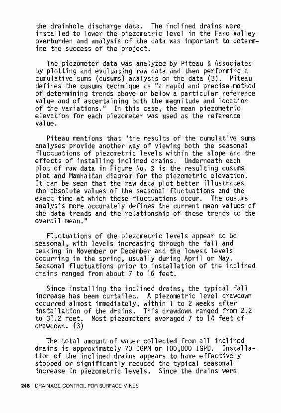
the drainhole discharge data. The inclined drains were installed to lower the piezometric level in the Faro Valley overburden and analysis of the data was important to determine the success of the project.
The piezometer data was analyzed by Piteau & Associates by plotting and evaluating raw data and then performing a cumulative sums (cusums) analysis on the data (3). Piteau defines the cusums technique as 11 a rapid and precise method of determining trends above or below a particular reference value and of ascertaining both the magnitude and location of the variations." In this case, the mean piezometric elevation for each piezometer was used as the reference value.
Piteau mentions that "the results of the cumulative sums analyses provide another way of viewing both the seasonal fluctuations of piezometric levels within the slope and the effects of installing inclined drains. Underneath each plot of raw data in Figure No. 3 is the resulting cusums plot and Manhattan diagram for the piezometric elevation. It can be seen that the~raw data plot better illustrates the absolute values of the seasonal fluctuations and the exact time at which these fluctuations occur. The cusums analysis more accurately defines the current mean values of the data trends and the relationship of these trends to the overall mean. 11
Fluctuations of the piezometric levels appear to be seasonal, with levels increasing through the fall and peaking in November or December and the lowest levels occurring in the spring, usually during April or May. Seasonal fluctuations prior to installation of the inclined drains ranged from about 7 to 16 feet.
Since installing the inclined drains, the typical fall increase has been curtailed. A piezometric level drawdown occurred almost immediately, within 1 to 2 weeks after installation of the drains. This drawdown ranged from 2.2 to 31.2 feet. Most piezometers averaged 7 to 14 feet of drawdown. (3)
The total amount of water collected from all inclined drains is approximately 70 IGPM or 100,000 IGPD. Installation of the inclined drains appears to have effectively stopped or significantly reduced the typical seasonal increase in piezometric levels. Since the drains were
248 DRAINAGE CONTROL FOR SURFACE MINES
0 ?; z )> Gl m 0 0 z -I :IJ 0 r Qo 0 m
~ '--i m ;Q z Gl
~ "Tl )> :IJ 0 0 -u m z -u =i :s::: z m
N
"" <O
!='.
~~~s ~~~;
-
1-CtL.E Pt-1-:3 DAT<
I"'°"' I ~~I~ I 'I.a 1 MM I - I IMl ! ~ I .a.t,.l l .Ill.Ko 1 Kn I OC"I I "'°"' 1 :~·i~ I '1..1 I - I A""I I - , ,u.c I .1JU 1 JMx. i K"1 I CX"1 I "'°"' I
P-2'!0
8o
-2.6 4163,9•
" l+H>9.0' • 4164.8' 416].2' +2.5
411ot-JZ~~~~~k:z!::z!:?22?2Zd~~~~~~~~~~~~~~~k~~~~===="'.'fz::::z::::~~I 4168 4166.5
4165 MANHATTANOIAGRAMOFMEANPIEZOMETRICELEVATION 4163
""l 4\40
4135
4130
4125
4120
4115
~1~ 200 -· - ••• -
": '
CUMULATIVE SUMS PIEZOMETRIC ELEVATION PLOT
SYMBOLS
Period of unusually high rainfal 1 i Approxim<ite start of night k temperatures < 0° C I
Approximate start of 24 hour I temperatures < 0° C ... Number and completion date of I relevant inclined drain
''"~~rnffe~~ 1+131+.2 ;,..nnn»h 4132 4130 4128 4126
"""'-JSNM.. ...., "'-1.EY CEWmV<N;
' ...... -=-~--~=~:==--
~ g MANHATTAN OIAGRAii OF iiEAN PIEZOMETRIC ELEVATION CIJ5l.MS ANAL)SIS OF PIEZOMETRI C
ELEllZITION ( PH-3)
Figure 3 - Cusums Analysis of Piezometric Elevation. Note large decrease in piezometric elevation after drainholes were installed in September, 1977.
21arn
9
installed in September, 1977, no major failures have taken place in the Faro Valley alluvium.
REDIVERSION OF THE WATER IN THE 4030 DITCH
An alternative to the metal flume that carried the Faro Valley water out of the pit along the 4030 bench was needed. The reason for this was that the existing drainage system along the 4030 ditch was in an area of questionable slope stability and also it was not located on a final pit wall, thus eventually requiring relocation of the ditch when the mining phase approached this area.
Any new drainage system adopted had to provide adequate control of both subsurface and surface water. Therefore, it was advisable to continue collecting the water on the 4030 bench level below the Faro Valley because this location was just below the bedrock/alluvium contact and much of the groundwater seepage surfaced at or before this contact.
The alternative to draining the Faro Valley water around the east side of the pit, as it was done, was to drain it to the west. This could be achieved either at a constant bench elevation until the water was out of the pit, or else drained into the existing sump in the northwest corner by the pit pumphouse (see Figure No. 2).
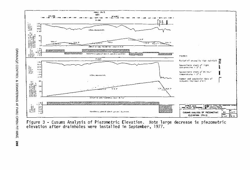
A pipeline was constructed using 8 inch Series 40 polyethylene pipe from the 4030 bench below Faro Valley to the pit pumphouse sump in the northwest corner of the pit. It was decided to use a pipeline for diverting the water rather than a ditch and metal flume because it would provide much more flexibility in the course chosen for diversion and it would be easier to maintain (there would be no overflows or ice buildups as with the flume). (See Figure No. 4)
A sump was drilled, blasted and dug in bedrock on the 4030 elevation for use in collecting the water to be diverted down the pipeline. The sump was located so that it could best intercept all the drainage out of Faro Valley. The easiest place to collect all the water would have been just east of the inclined drainhole locations, but this was not an acceptable location because of the slope instability found immediately below on the north pit wall. Even a small failure here could ruin a sump and the escaping water could seriously affect the remaining stability of this section of the pit wall. The sump was constructed on a stable section
250 DRAINAGE CONTROL FOR SURFACE MINES
i;llf-<-. • ~:::.----~ ..... !-.-~· ·'
l="ARo . J) VAL.IJ!.Y i Ii/ ,
4:o3o : -- $1J':'P.: ..... .,_.--. ~c--
Figure No. 4 - Location of pipelines carrying water from the Faro Valley area to the pit bottom pumphouse.
' .~ -
--...:.....--:,~~·J"' ... llllli-c•~-~~~~--~-. -~ ·:~t!:·· t..-'c:~ -~-"~. .,.._ :"-.. :~}: ·1:~··~ ,1i -,,~
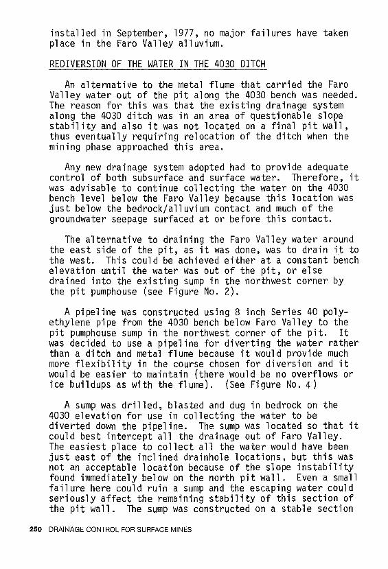
Figure No. 5 - Water collected in the pit bottom (25 million U.S. gallons, Sept./78). All this water has since been pumped out of the pit using the new pumping system
DRAINAGE CONTROL & DEWATERING AT FARO OPEN PIT MINE 251
of the 4030 bench below Faro Valley and water was ditched into it from both the east and the west. A concrete dam was constructed to decant water from the sump and the pipelines were anchored in the concrete. Two pipelines were connected to the sump so that if one got blocked or frozen up the other could be opened up and used. The pipelines were designed so that the sump drained by gravity feed and no sump pumping was necessary. Approximately 300 U.S. GPM flow down the pipeline to the pit bottom sump. This amount will triple during spring runoff.
PIT BOTTOM DEWATERING
Problem
In 1975, plans for a final drainage system for the Faro open pit were proposed because the mining phase had reached the stage where the pit bottom was encountering the regional water table. Up until this time, approximately 400 U.S. GPM were being pumped from the bottom of the pit through an old exploration adit. This old pumping system did not have the capability of lifting the water over the existing pit wall and it was only because of the existence of the adit that dewatering was possible. Recirculation of water between the adit and the pit was thought to have existed, contributing to the water control problems in the pit bottom. These problems combined with the fact that the adit was scheduled to be mined out in early 1977, necessitated installation of an alternate dewatering system to prevent flooding of the pit bottom. If flooding had occurred, the ore supply would have been cut off (see Figure No. 5)
Solution
There was a large flat area (300 feet by 400 feet) in the northwest corner of the pit that could accommodate a sump and pumphouse for use in a new dewatering system. This was an advantageous location because the pit wall surrounding the area was final and the area itself would not be mined out and would be accessible during all the successive mining phases. It was decided to install the main components of an in-the-pit dewatering system at this location.
The solution of installing deep wells outside the ultimate pit perimeter to lower the water table in the pit area was rejected because of the r.ost and because of the size and depth of the pit. (The open pit will eventually
252 DRAINAGE CONTROL FOR SURFACE MINES
reach 1,000 feet in depth and will be 4,800 feet long by 3,000 feet wide).
The pit bottom dewatering system included:
1) Two pumps and motors
2) Two pipelines
3) Four submersible sump pumps
4) One transformer
5) Two electric switch gears
6) Sump
7) Construction of a protective building around the pumps, the motors and the valve system
8) Steamer
9) Miscellaneous parts - valves, couplings, elbows, flow meters, electric heaters, etc.
An analysis of the above items was done to, hopefully, come up with the most efficient system.
When considering the selection of pumps and motors, the following criteria were applied:
1) Capable of handling fines in the water
2) Pump at a minimum of 270 feet total dynamic head
3) Pumping rate of 400 U.S. GPM
4) Minimum delivery time
5) Minimum power consumption
6) Durability
7) Parts 1 availability
8) Minimum cost
DRAINAGE CONTROL & DEWATERING AT FARO OPEN PIT MINE 253
After evaluating different pumps, a horizontal six inch standard centrifugal double stage pump with a V-belt drive was chosen because:
1) It could handle fines up to 0.5 inches.
2) It met the requirements for head and quantity of water.
3) It had a low R.P.M. (1,750 R.P.M.), thus minimizing the wear on the impeller.
4) A similar pump had already been used successfully in the pit.
5) The 75 H.P. motor and the V-belt would allow versatility in the pumping rate and in the total dynamic head.
After selecting the necessary pumps for use in the dewatering system, the choice and location of the pipelines had to be determined. The system incorporated two pipelines (one attached to each pump) that were self-draining, easily accessible and of minimum exposure to blasts and other mining activities. Three possible solutions were considered for the location of the pipelines and a decision analysis was done on the three alternatives to determine the best solution.
The pipeline route that was used was recommended mainly because of the lower head over which the water was pumped in comparison to the other possible routes. The lower head allowed the utilization of polyethylene pipe, resulting in greater manoeuverability as compared to steel pipe, and also of smaller pumps at lower R.P.M., resulting in lower power consumption and less maintenance.
The two pipelines were constructed of six inch Series 160 polyethylene pipe and were both 2,900 feet long. The pipelines run from the pumphouse at the 3790 pit elevation up the pit wall to a wide bench at the 4030 elevation and along this bench until out of the pit area where the water is discharged (see Figure No. 2).
The pumping operation is variable with high pumping rates in the springtime and lower rates in the winter. To eliminate the irregular operation of the pumps, to keep a
254 DRAINAGE CONTROL FOR SURFACE MINES
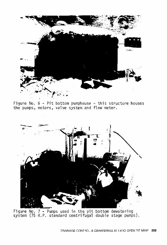
Figure No. 6 - Pit bottom pumphouse - this structure houses the pumps, motors, valve system and flow meter.
Figure No. 7 - Pumps used in the pit bottom dewatering system (75 H.P. standard centrifugal double stage pumps).
DRAINAGE CONTROL & DEWATERING AT FARO OPEN PIT MINE 255
constant flow through the pipeline, thus preventing freezing, and to facilitate the settling of the fines and protect the pumps, it was necessary to have a sump near the pumphouse on the 3790 bench. A 25 foot by 15 foot by 9 foot concrete sump was constructed with a capacity of 25,000 gallons. The sump had to be waterproofed to prevent recirculation of water back into the pit bottom.
An insulated and heated metal building on skids was constructed to protect the major components of the dewateri ng system from flyrock and freezing. This structure houses the pumps, motors, valve system and flow meters.
In the event of a forced shutdown in mid-winter and a failure of the automatic draining system to function properly, freezing of the pipelines would occur. A steamer is, therefore, available for use in case of a freeze-up and it has proven to be a practical method of thawing out a frozen pipeline in very cold weather.
Basically, the main components of the pit bottom dewatering system are the pumphouse, pipelines and sump. This pumping system was justified and necessary to keep a dewatered pit bottom to ensure a continuous ore supply to the mill.
FUTURE DEWATERING PLANS
The Faro Creek diversion ditch, the inclined drainholes in Faro Valley and the pit bottom pumping system all combine to provide an adequate dewatering program for the mine, but continual upgrading of the system is necessary. New testing is being carried out to find efficient methods for continuing advanced dewatering in the bottom of the open pit. Plans include drilling 12 to 15 inch diameter holes, using the production blasthole drill rigs, in which submersible pumps can be installed. Pumping tests will be done to gain further knowledge of the necessary well spacings and depths required to ensure a dewatered ore phase before mining begins.
Development of the Small Faro Deposit (Zone 2) will start in 1979 and drainage control measures are being prepared in co-ordination with the mine design.
Mine dewatering of the Faro open pit is an on-going necessity and research and testing will be carried on to
256 DRAINAGE CONTROL FOR SURFACE MINES
ensure adequate control of water problems.
ACKNOWLEDGEMENTS
The writer would like to thank D. Gregoire, Chief Engineer, and D. Hanson, Exploration Geologist, of Cyprus Anvil Mining Corporation for their contributions to this paper based on their past involvement in mine dewatering of the Faro open pit mine.
REFERENCES
1. MORRISON, K. I., "Inspection Report, Anvil Mines - Water at Pit," Ripley, Klohn & Leonoff, File VA1711, August 22' 1972
2. DICK, R. C., "Results of Test Holes Drilled for Stratigraphy and Groundwater Observations in Faro Valley Overburden," Piteau, Gadsby, Macleod Limited, 75-055, February 27, 1976
3. STEWART, A. F. and PITEAU, D. R., "Report on Drainhole Installation and Related Monitoring for Groundwater Ora inage of Faro Valley, 11 Piteau & Associates, January, 1978
DRAINAGE CONTROL & DEWATERING AT FARO OPEN PIT MINE 257