drainage impact anaylsis for the little america development
TRANSCRIPT

DRAINAGE IMPACT ANAYLSIS FOR THE
LITTLE AMERICA DEVELOPMENT
In Support of a Major Plan Amendment
June 26, 2013
Prepared by:
JE Fuller/Hydrology & Geomorphology, Inc.
1 W. Deer Valley Rd., Ste. 101 Phoenix, AZ 85027
Prepared for:
Little America Hotels & Resorts, Inc. 2515 E Butler Ave
Flagstaff, AZ 86004

Drainage Impact Analysis For the Little America Development
Executive Summary
June 2013 Page: i
Executive Summary
The Drainage Impact Analysis documents the hydrologic and hydraulic conditions resulting from the proposed change in land-use for the Little America Development. It should be noted that the hydrologic and hydraulic modeling, computational approaches and drainage concepts presented in this report will require further refinement as development proceeds.
Based on coordination with the City of Flagstaff stormwater staff, the Drainage Impact Analysis focused on the following four objectives:
Objective No. 1. Determine the minimum level of on-site Low Impact Development (LID) stormwater storage required for the site.
Outcome: Minimum level of LID storage for the proposed development was calculated to be 316,384 cu. ft. Discussion regarding land-use and required LID stormwater storage is included in Section 2.2.
Objective No. 2. Based on HEC-1 hydrologic modeling, demonstrate that there is no increase (0.00 ft.) in the ponding elevation at “Lake Continental” (HEC-I ID “Outlet”).
Outcome: To demonstrate that there is a no-rise condition at “Lake Continental”, the Little America Development will need to detain a minimum of 18 acre-feet of on-site storage. Discussion regarding on-site detention volume is included in Section 2.3.2.
Objective No. 3. Using the HEC-1 discharges, assess the project impacts at the E. Butler Avenue crossing of the Rio de Flag (HEC-1 ID “EFG”) assuming a fully developed site with no on-site storage.
Outcome: A hydrologic model was prepared assuming a fully developed site with no on-site storage. Resultant peak discharges were used to evaluate the road crossing at E. Butler Avenue. The hydraulic model results show an increase at the E. Butler Avenue crossing of 0.02 ft., which is less than the 0.1 ft. allowed by the City. Discussion regarding the E. Butler Avenue crossing of the Rio de Flag is provided in Section 3.1.
Objective No. 4. Assess project impact on the Rio de Flag floodplain.
Outcome: A hydraulic model (HEC-RAS model) was prepared to compare the Rio de Flag’s existing and proposed 100-year floodplain boundaries. The proposed condition model included preliminary Golf Course grading, minor golf cart structures and proposed future road crossing at the southeast property boundary. Minor impacts to the floodplain occur within and adjacent to the Little America Development, primarily upstream of proposed structures crossing the Rio de Flag. Discussion regarding the Rio de Flag floodplain analysis is included in Section 3.2.

Drainage Impact Analysis For the Little America Development
Table of Contents
June 2013 Page: ii
Table of Contents
1 Introduction ......................................................................................................................... 1-1
1.1 Report Purpose ............................................................................................................. 1-1
1.2 Proposed Land-Use Plan Description ............................................................................ 1-1
1.2.1 Resort/Conference Center ..................................................................................... 1-1
1.2.2 Low/Medium/High Density Residential ................................................................. 1-1
1.2.3 Commercial ............................................................................................................ 1-2
1.2.4 Golf Course Amenities ........................................................................................... 1-2
1.3 Drainage Impact Analysis Objectives ............................................................................ 1-2
2 Simplified Stormwater Storage Evaluation .......................................................................... 2-1
2.1 Hydrologic Modeling ..................................................................................................... 2-1
2.2 Land Use Changes and LID Volumes ............................................................................. 2-1
2.3 Hydrologic Modeling Results......................................................................................... 2-4
2.3.1 Proposed Land Use Change - Without On-Site Stormwater Storage .................... 2-4
2.3.2 Proposed Land Use Change – With Required On-Site Stormwater Storage ......... 2-5
2.4 On-Site Stormwater Storage Summary ......................................................................... 2-6
2.4.1 LID Storage Volume................................................................................................ 2-6
2.4.2 General Stormwater Storage Volume.................................................................... 2-6
3 Hydraulic Analysis ................................................................................................................ 3-1
3.1 E. Butler Avenue crossing of the Rio de Flag ................................................................. 3-1
3.1.1 E. Butler Avenue Hydraulic Evaluation .................................................................. 3-1
3.1.2 E. Butler Avenue Hydraulic Evaluation Results ...................................................... 3-1
3.2 Rio de Flag Floodplain ................................................................................................... 3-3
3.2.1 Topography ............................................................................................................ 3-3
3.2.2 Steady Flow Data ................................................................................................... 3-3
3.2.3 Downstream Boundary Conditions ........................................................................ 3-3
3.2.4 Flow Regime ........................................................................................................... 3-3
3.2.5 Development of HEC-RAS Model Input Data ......................................................... 3-4
3.2.5.1 Stream Centerline ........................................................................................... 3-4
3.2.5.2 Cross-Sectional Cut Lines ................................................................................ 3-4
3.2.5.3 Bank Stations .................................................................................................. 3-4
3.2.5.4 Flow Path Centerlines ..................................................................................... 3-4
3.2.5.5 Cross-Section Roughness Coefficients (Manning’s n-Value) .......................... 3-4
3.2.5.6 Proposed Conditions Hydraulic Structures..................................................... 3-5
3.2.6 HEC-RAS Modeling Results .................................................................................... 3-5
3.2.7 Limitations of Modeling Results ............................................................................ 3-6
3.2.8 Hydraulic Modeling Conclusions ............................................................................ 3-7

Drainage Impact Analysis For the Little America Development
List of Tables
June 2013 Page: iii
List of Tables
Table 2–1 Percent Impervious for Proposed Land Uses ............................................................. 2-1
Table 2–2 Percent Impervious and LID Volume Requirement per Land-Use Plan Area and USACE HEC-1 Sub-Area ............................................................................................................................ 2-3
Table 2–3 HEC-1 Changes in RTIMP for Sub-Areas F3 and G ...................................................... 2-4
Table 2–4 USACE Existing Condition HEC-1 Model ..................................................................... 2-4
Table 2–5 Proposed Condition HEC-1 Model.............................................................................. 2-5
Table 2–6 USACE HEC-1 Model (With Adjusted Percent Impervious) ........................................ 2-5
Table 3–1 E. Butler Avenue Crossing WSE Change ..................................................................... 3-1
Table 3–2 Rio de Flag Proposed Structures ................................................................................ 3-5
Table 3–3 Floodplain Elevation Changes .................................................................................... 3-6
List of Figures
Figure 1-1: Site Location and Overview ...................................................................................... 1-3
Figure 2-1: Proposed Land-Use Plan Area .................................................................................. 2-2
Figure 3-1: E. Butler Avenue Crossing ......................................................................................... 3-2
List of Appendices
Appendix A. Hydrology Supporting Data
Appendix B. Hydraulics Supporting Data
Appendix C. Project Data Disk

Drainage Impact Analysis For the Little America Development
Introduction
June 2013 Page: 1-1
1.1 Report Purpose
In support of the Little America major land-use plan amendment, the Drainage Impact Analysis for the Little America Development (Drainage Impact Analysis) is being submitted to the City of Flagstaff (City) for review and approval. The Drainage Impact Analysis documents the hydrologic and hydraulic conditions resulting from the proposed change in land-use. It should be noted that the hydrologic and hydraulic modeling, computational approaches and drainage concepts presented in this report will require further refinement as development proceeds.
A site location and overview map is provided as Figure 1-1, shown below.
1.2 Proposed Land-Use Plan Description
As discussed above, the Drainage Impact Analysis has been prepared in support of a proposed change in land-use. Four primary land-use types are being proposed within the Little America Development: resort/conference center, low/medium/high density residential, park/open space, commercial and golf course amenities.
The vision for the Little America property is a mixed-use, resort development with hotel and conference facilities that will expand and complement the current facilities at the Little America Flagstaff Hotel. The conceptual master plan capitalizes on the opportunities present on the property by creating a vibrant mixed-use neighborhood where residents can live, work and play at virtually the center of the Flagstaff City limits. The proposed plan includes retail and office opportunities adjacent to I-40 and E. Butler Avenue with high density residential within walking distance. The gently rolling terrain combined with a large area of relatively flat terrain provides the opportunity for a wide range of recreational activities including golf, hiking, running, biking trails connected within the property and to the Flagstaff Urban Trail System (FUTS). The diverse density within the residential areas provides for a mix of housing types and price ranges with proximity to the retail and office space as well as the resort and recreation amenities.
A brief description of each land-use category is provided below. Proposed land-use hydrology is discussed in Section 2. The conceptual land-use plan for the Little America Development is shown on Figure 2-1.
1.2.1 Resort/Conference Center
The new hotel and conference center is anticipated to include approximately 200 hotels rooms, 40,000 square feet of conference space and resort amenities that include pool, spa, wedding/event space, tennis, etc.
1.2.2 Low/Medium/High Density Residential
The concept plan supports mixed-uses and a significant range of residential types within the 1,391 units noted on the plan. These residential types include: for rent/leasable apartments, workforce housing, stacked condo, brownstones, townhomes, duplex, detached patio homes,
1 Introduction
Drainage Impact Analysis For the Little America Development
Introduction
June 2013 Page: 1-2
mix of single family detached homes, and high-end resort residential (wrapping the resort parcel and branded by the proposed hotel).
1.2.3 Commercial
The commercial/mixed-use area may include neighborhood retail such as a local market, gas station, movie theater, restaurants and other goods and services for residents, visitors and commuters along with the potential of office suites above retail.
1.2.4 Golf Course Amenities
Recreational opportunities include public parks, an 18-hole resort/public golf course and clubhouse as well as an integrated multi-use trail system connecting residents and visitors to homes, resort and recreational opportunities within the site and to the regional FUTS trail system in Flagstaff.
1.3 Drainage Impact Analysis Objectives
Based on coordination with the City of Flagstaff stormwater staff, the Drainage Impact Analysis focus is on the following 4 objectives:
Objective No. 1. Determine the minimum level of on-site Low Impact Development (LID) stormwater storage required for the site.
Objective No. 2. Based on HEC-1 hydrologic modeling, demonstrate that there is no increase (0.00 ft.) in the ponding elevation at “Lake Continental” (HEC-I ID “Outlet”).
Objective No. 3. Using the HEC-1 discharges, assess the project impacts at the E. Butler Avenue crossing of the Rio de Flag (HEC-1 ID “EFG”) assuming a fully developed site with no on-site storage.
Objective No. 4. Assess project impact on the Rio de Flag floodplain.

Drainage Impact Analysis For the Little America Development
Introduction
June 2013 Page: 1-3
Figure 1-1: Site Location and Overview

Drainage Impact Analysis For the Little America Development
Simplified Stormwater
Storage Evaluation
June 2013 Page: 2-1
2.1 Hydrologic Modeling
Hydrologic modeling for this project was based upon the existing condition HEC-1 model (Rd100byr.dat) provided by the City from the U.S. Army Corps of Engineers (USACE) Feasibility Report and Final Environmental Impact Statement, which is dated September 2000. The Technical Appendices Volume 1 of the USACE report can be referenced for additional details on the hydrology model used for this report. The USACE existing condition was used for the following:
Based on proposed development, determine if a water surface elevation (WSE) increase would occur at “Lake Continental”.
Based on proposed development, determine if a WSE increase greater than 0.1 feet would occur at the Rio de Flag crossing of E. Butler Avenue near Fox Glenn Park.
Modification of the USACE existing condition HEC-1 model was performed to determine hydrologic and hydraulic impacts resulting from the proposed development at “Lake Continental” and E. Butler Avenue.
2.2 Land Use Changes and LID Volumes
The proposed land-use conditions were modeled by adjusting the percent impervious (RTIMP) for HEC-1 Sub-Areas F3 and G. No other changes were made for the exponential loss rate data (LE), base flow characteristics (BF), or the given unit graph (UI). This modeling approach is in-line with the approach taken by the USACE during development of their Future Land Use HEC-1 model, i.e. USACE only modified each Sub-Area impervious percent to reflect future conditions.
The applied impervious percentages for the proposed land-uses are consistent with values found in Table 2-2a of the NRCS TR-55 and Figure 2-3 of the ADOT Hydrology Manual. See Figure 2-1 for Future Land Use and Figure A- 1 for Future Land Use with USACE basin overlay. Average percent impervious area per proposed land-use category are shown in Table 2–1. In addition, included in Table 2–2 are the percent impervious area and LID stormwater storage volume requirement per Land Use Plan Area and USACE HEC-1 Sub-Area [Objective No. 1 – Section 1.3]. As seen in Table 2–2, several of the proposed land-use areas can be found in both Sub-Area F3 and G.
Table 2–1 Percent Impervious for Proposed Land Uses
Proposed Land Use Categories Average % Impervious
Commercial 85
Resort/Hotel/High Density Residential 70
Lower Density Residential 40
Golf Course No Change in imperviousness anticipated
2 Simplified Stormwater Storage Evaluation

Drainage Impact Analysis For the Little America Development
Simplified Stormwater
Storage Evaluation
June 2013 Page: 2-2
Figure 2-1: Proposed Land-Use Plan Area

Drainage Impact Analysis For the Little America Development
Simplified Stormwater
Storage Evaluation
June 2013 Page: 2-3
Table 2–2 Percent Impervious and LID Volume Requirement per Land-Use
Plan Area and USACE HEC-1 Sub-Area
Land
Use
Plan
Area
Acres Units/Acre 1Applied %
Impervious
Impervious
Area
(Acres)
UASCE
HEC-1
Sub-Area
3LID Volume
(cu ft.)
Area A 5.81 20 70% 4.07 G 14,763
Area B 4.77 14 70% 3.34 F3 12,121
Area C 10.15 14 70% 7.11 F3 25,791
Area D 4.55 16 70% 3.19 F3 11,562
Area E 6.94 14 70% 4.86 F3 17,635
Area F 2.93 18 70% 2.05 F3 7,445
Area G 3.42 18 70% 2.39 G 8,690
Area H 4.10 20 70% 2.87 G 10,418
Area I 2.92 12 70% 2.04 G 7,420
Area J 4.10 16 70% 2.87 F3 10,418
Area K 4.09 12 70% 2.86 F3 10,393
Area L 4.69 14 70% 3.28 F3 11,917
Area M 3.34 12 70% 2.34 F3 8,487
Area N 6.07 12 70% 4.25 F3 15,424
Area O 7.55 12 70% 5.29 F3 19,185
Area P 8.84 12 70% 6.19 F3 22,462
Area Q 4.00 4 40% 1.60 F3 5,808
Area R 3.60 4 40% 1.44 F3 5,227
Area S 5.50 4 40% 2.20 F3 7,986
Area T 7.80 4 40% 3.12 F3 11,326
Area U 3.20 8 40% 1.28 F3 4,646
Area V 5.59 8 40% 2.24 F3 8,117
Area W 4.10 8 40% 1.64 F3 5,953
Area X 3.00 4 40% 1.20 F3 4,356 2Area A1 4.56 NA 85% 3.88 G 0
2Area A2 8.64 NA 85% 7.34 G 0
Area A3 5.78 NA 85% 4.91 G 17,834
Area B-1 9.70 NA 70% 6.79 F3 24,648
Area B-2 2.50 NA 70% 1.75 F3 6,353
152.24 98.38 316,384 1Impervious percentages to the proposed land-uses that were consistent with values found in Table 2-2a of the
NRCS TR-55 and Figure 2-3 of the ADOT Hydrology Manual 2Area contains existing impervious surfaces that are consistent with the proposed % imperviousness. These
areas were removed from the computations. 3LID Volume = (Impervious Area)(1-Inch Runoff)
Drainage Impact Analysis For the Little America Development
Simplified Stormwater
Storage Evaluation
June 2013 Page: 2-4
2.3 Hydrologic Modeling Results
2.3.1 Proposed Land Use Change - Without On-Site Stormwater Storage
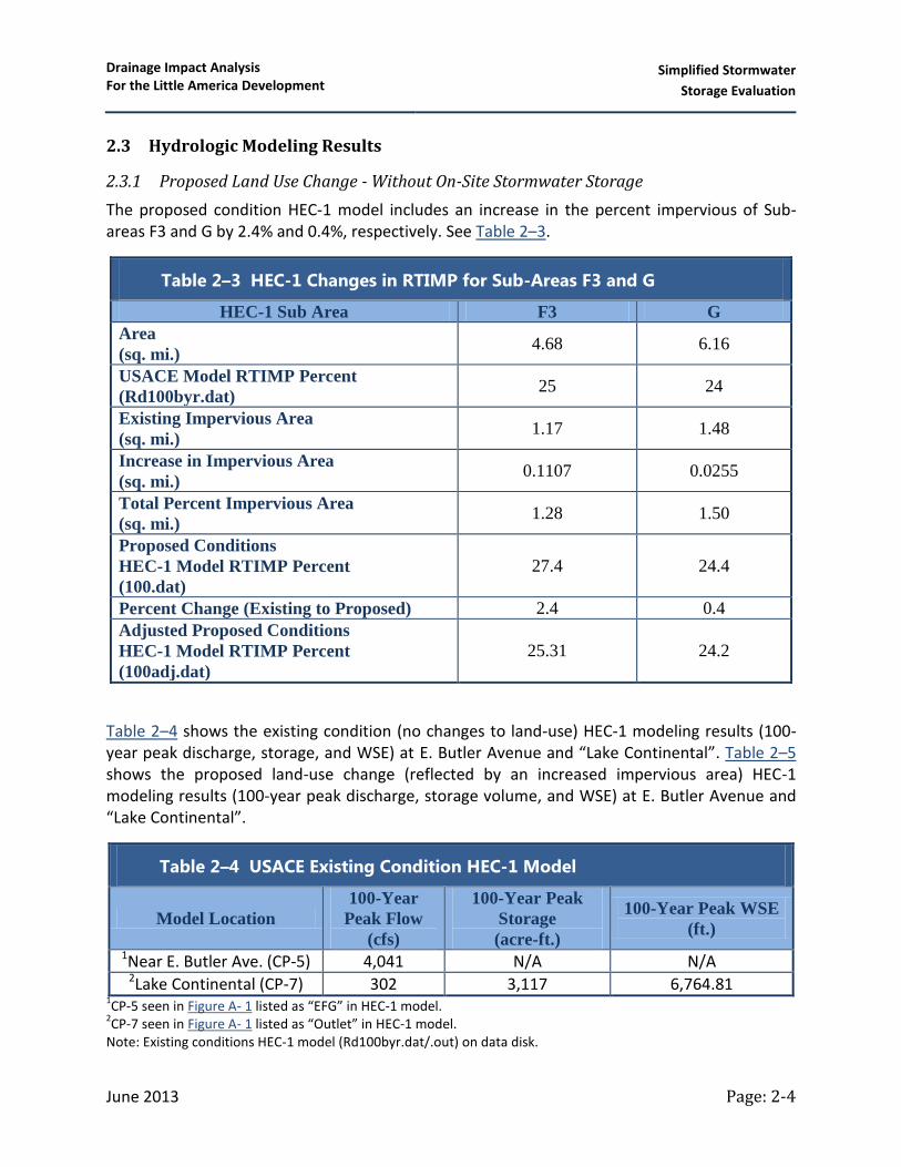
The proposed condition HEC-1 model includes an increase in the percent impervious of Sub-areas F3 and G by 2.4% and 0.4%, respectively. See Table 2–3.
Table 2–3 HEC-1 Changes in RTIMP for Sub-Areas F3 and G
HEC-1 Sub Area F3 G
Area
(sq. mi.) 4.68 6.16
USACE Model RTIMP Percent
(Rd100byr.dat) 25 24
Existing Impervious Area
(sq. mi.) 1.17 1.48
Increase in Impervious Area
(sq. mi.) 0.1107 0.0255
Total Percent Impervious Area
(sq. mi.) 1.28 1.50
Proposed Conditions
HEC-1 Model RTIMP Percent
(100.dat)
27.4 24.4
Percent Change (Existing to Proposed) 2.4 0.4
Adjusted Proposed Conditions
HEC-1 Model RTIMP Percent
(100adj.dat)
25.31 24.2
Table 2–4 shows the existing condition (no changes to land-use) HEC-1 modeling results (100-year peak discharge, storage, and WSE) at E. Butler Avenue and “Lake Continental”. Table 2–5 shows the proposed land-use change (reflected by an increased impervious area) HEC-1 modeling results (100-year peak discharge, storage volume, and WSE) at E. Butler Avenue and “Lake Continental”.
Table 2–4 USACE Existing Condition HEC-1 Model
Model Location
100-Year
Peak Flow
(cfs)
100-Year Peak
Storage
(acre-ft.)
100-Year Peak WSE
(ft.)
1Near E. Butler Ave. (CP-5) 4,041 N/A N/A 2Lake Continental (CP-7) 302 3,117 6,764.81
1CP-5 seen in Figure A- 1 listed as “EFG” in HEC-1 model.
2CP-7 seen in Figure A- 1 listed as “Outlet” in HEC-1 model.
Note: Existing conditions HEC-1 model (Rd100byr.dat/.out) on data disk.

Drainage Impact Analysis For the Little America Development
Simplified Stormwater
Storage Evaluation
June 2013 Page: 2-5
Table 2–5 Proposed Condition HEC-1 Model
Model Location
100-Year Peak
Flow
(cfs)
100-Year Peak
Storage
(acre-ft.)
100-Year Peak WSE
(ft.)
Near E. Butler Ave. (CP-5) 4,055 N/A N/A
Lake Continental (CP-7) 302 3,139 6,764.85 Note: Proposed conditions HEC-1 model (100.dat/.out) on data disk.
As seen from Table 2–4 and Table 2–5, changes in land-use (increased impervious area) without mitigation storage volume in place, results in a WSE increase of 0.04 feet at “Lake Continental”. This increase violates the “no rise” requirement for WSE requested by the City. A discussion in regards to meeting the “no rise” requirement with the use of on-site stormwater storage is provided below in Section 2.3.2.
2.3.2 Proposed Land Use Change – With Required On-Site Stormwater Storage
[Objective No. 2 – Section 1.3]
Based on the above discussed WSE increase of 0.04 feet at “Lake Continental” (Section 2.3.1), the City requires the proposed development to retain a portion of the stormwater runoff volume created by the increase in impervious area.
To meet the “no rise” criteria at “Lake Continental”, the proposed conditions percent impervious was incrementally decreased for Sub-Areas F3 and G until a “no rise” condition was met at “Lake Continental”. The resulting allowable runoff volume, associated with this modeled difference in proposed condition percent imperviousness is 18 acre-feet (see Table 2–6).
Table 2–6 USACE HEC-1 Model (With Adjusted Percent Impervious)
Model Location
100-Year
Peak Flow
(cfs)
100-Year
Runoff Volume
(acre-ft.)
100-Year Peak
WSE
(ft.) 1Lake Continental (CP-7)
Proposed Condition 302 3,139 6,764.85
Lake Continental (CP-7) Proposed Condition - Adjusted 302 3,121 26,764.81
Difference 18 1Sub-Areas F-3 and G percent impervious area changed as shown in Table 2–3. (HEC-1 Model 100adj.out)
2WSE matches the UASCE existing conditions WSE at “Lake Continental” (See Table 2–4)
Note: Adjusted conditions HEC-1 model (100adj.dat/.out) on data disk.
The runoff volume will to be detained on-site through the use of stormwater storage basins and or other LID related facilities. Stormwater storage basins will be further assessed during subsequent, more detailed design phases of the Little America Development.

Drainage Impact Analysis For the Little America Development
Simplified Stormwater
Storage Evaluation
June 2013 Page: 2-6
2.4 On-Site Stormwater Storage Summary
On-site storage will be composed of Low Impact Development (LID) storage volume and general stormwater storage volume.
2.4.1 LID Storage Volume
LID storage volume is intended to retain the initial 1-inch of rainfall runoff. Across the proposed development, this 1-inch of rainfall runoff equates to 7.3 acre-feet (316,384 cu. ft. ÷ 43,560 ft./acre) of required LID storage volume (see Table 2–2).
During the design phase of the project, implementation of LID storage will be based on Best Management Practices (BMPs) as outlined in the City’s Low Impact Development, Guidance Manual for Site Design and Implementation. A Master Stormwater LID Plan for the entire site must be prepared to account for phased development. At minimum, each phase of the development will include the LID facilities from the Master Stormwater LID Plan. Interim temporary LID facilities may be required for project phasing.
2.4.2 General Stormwater Storage Volume
General stormwater storage volume will be implemented in order to ensure a “no rise” condition at “Lake Continental”. As discussed in Section 2.3, the required on-site retention volume to achieve this is 18 acre-feet, which will be phased with development.
General stormwater storage facilities will be placed to detain runoff volume through the use of in-line storage basins. In-line storage basins are located within significant drainages at the following strategic locations:
1. Within and adjacent to proposed golf course.
2. Upstream of roadway crossings.
3. Just upstream of development boundaries.
4. Underground storage within commercial and high density residential parcels along E. Butler Avenue if space constraints warrant.
Stormwater storage basins are not shown on figures; however, stormwater storage basins will be phased as development progresses. It should be noted that stormwater storage basins will not be located within the Rio de Flag 100-year floodplain.

Drainage Impact Analysis For the Little America Development
Hydraulic Analysis
June 2013 Page: 3-1
3.1 E. Butler Avenue crossing of the Rio de Flag
[Objective No. 3 – Section 1.3]
3.1.1 E. Butler Avenue Hydraulic Evaluation
The City provided JEF with a HEC-RAS model (foxglenndivided.prj) for the Rio de Flag, which included cross-section in the vicinity of E. Butler Avenue. This model was prepared as part of the Floxglenn Development LOMR (April 2004). The following procedure was used to evaluate the hydraulic impact at E. Butler Avenue that is associated with the nominal increase in 100-year peak discharge for the proposed Little America Development land-use changes (discussed in Section 2.3);
1) Discharges used for the E. Butler Avenue hydraulic evaluation are 4,041 cfs and 4,055 cfs for existing and proposed conditions land-uses, respectively. (See Table 2–4 and Table 2–5.
2) The Foxglenn HEC-RAS model was developed using the Effective FEMA 100-year discharge of 3,250 cfs. The downstream boundary condition for the Effective model was a fixed water surface elevation of 6,773.9 feet at model cross-section 11.32. Per this study, the existing and proposed 100-year discharges are 4,041 cfs and 4,055 cfs, respectively. Given this increase in 100-year discharge, for this study, the downstream boundary condition was changed to normal depth with a slope of 0.00375 ft./ft.
3.1.2 E. Butler Avenue Hydraulic Evaluation Results
Existing and proposed WSE at HEC-RAS Cross-Section 11.455 (upstream cross-section at E. Butler Avenue, FEMA identified Cross-Section AT, See Figure 3-1) were compared to determine magnitude of the change. The results show a minor increase in water surface elevation, but within the 0.1 foot increase allowable by the City (see Table 3–1).
Table 3–1 E. Butler Avenue Crossing WSE Change
Cross-
Section ID
WSE using Existing
USACE Peak Discharge (ft.)
WSE using Developed
USACE Peak Discharge (ft.)
Difference (ft.)
11.455 6779.10 6779.12 0.02
3 Hydraulic Analysis

Drainage Impact Analysis For the Little America Development
Hydraulic Analysis
June 2013 Page: 3-2
Figure 3-1: E. Butler Avenue Crossing
HEC-RAS Cross section 11.455

Drainage Impact Analysis For the Little America Development
Hydraulic Analysis
June 2013 Page: 3-3
3.2 Rio de Flag Floodplain
[Objective No. 4 – Section 1.3]
The purpose of the hydraulic modeling was to compare the Rio de Flag’s existing and proposed 100-year floodplain boundaries. The proposed condition floodplain modeling includes future golf course grading and associated structures. It is the intent of the Little America Development to provided assurance that for subsequent design of golf course grading, a low impact approach will be implemented and maintained within the Rio de Flag floodplain. Furthermore, the intent of the golf course grading is to remain out of the delineated floodway.
Existing and proposed HEC-RAS models were developed by JE Fuller (RiodeFlag.prj). Hydraulic modeling was performed using the U.S. Army Corps of Engineers HEC-RAS software, version 4.1. Computations are in accordance with the guidelines presented in the City’s Stormwater Management Design Manual (July 2000). In addition, HEC-RAS models were developed using HEC-GeoRAS software, which is an extension for use with ArcGIS and was developed through a Cooperative Research Agreement between the USACE Hydrologic Engineering Center and ESRI Inc.
HEC-RAS model output tables and cross-section plots are provided in Appendix B and the electronic model is included on the Data Disk in Appendix C. Location of model cross-sections are shown on the Existing Condition and Proposed Condition floodplain exhibits (Figure B- 1 and Figure B- 2, respectively), located in Appendix B.
3.2.1 Topography
Existing condition, 2-foot contour topography (NAVD 88) was used for development of a digital terrain model (DTM), which was then used to cut HEC-RAS cross-sections with HEC-GeoRAS. It should be noted that points and break lines were not provided to JEF with the topography.
3.2.2 Steady Flow Data
HEC-RAS models were developed for existing and proposed conditions using the Effective FEMA Discharge of 3,150 cfs.
3.2.3 Downstream Boundary Conditions
HEC-RAS model downstream boundary conditions were established from cross-sections 13.01 (FEMA Lettered Cross section BF). The starting water surface elevation at cross-section 13.01 is 6793.8 feet.
3.2.4 Flow Regime
As typical with FEMA most flood studies, a sub-critical flow regime was used for HEC-RAS modeling of the existing and proposed conditions. A sub-critical flow regime was selected for computation of “conservative” water surface elevations.

Drainage Impact Analysis For the Little America Development
Hydraulic Analysis
June 2013 Page: 3-4
3.2.5 Development of HEC-RAS Model Input Data
HEC-GeoRAS is an extension for use with ArcGIS and was developed through a Cooperative Research Agreement between the USACE Hydrologic Engineering Center and ESRI Inc. This tool has been designed to process geospatial data for HEC-RAS model development based on a DTM and complementary data sets. Conversely, this tool is also capable of exporting model results for use in ArcGIS processing. The HEC-GeoRAS import files applicable for this project include:
Stream centerline. Cross-sectional cut lines. Flow path centerlines.
3.2.5.1 Stream Centerline
The stream centerline defines the predominant center of flow during an event. Typically this line is identified by a stream’s thalweg. For HEC-RAS modeling of existing and proposed conditions, the stream centerline was taken from the Preliminary DFIRM database for the Rio de Flag. The stream centerline was not modified between models.
3.2.5.2 Cross-Sectional Cut Lines
Based on the stream centerline and a project DTM, a cross-section cut line defines a section’s geometry, length, location (River Station), and alignment to the flow. This cross-section information is processed by HEC-GeoRAS and converted to HEC-RAS format. Cross-section river stations are based on river-feet distances and start at the downstream cross-section, increasing in numeric value based upon the upstream length along the stream centerline.
For HEC-RAS modeling of existing and proposed conditions, a sufficient number of cross-sectional cut lines were placed to reflect changes in channel geometry, profile and roughness. Given the project’s intent to understand any impacts from golf course grading within the Rio de Flag, cross-section locations, alignments and geometries are coincidental for existing and proposed conditions.
3.2.5.3 Bank Stations
For HEC-RAS modeling of existing and proposed conditions, bank station locations are consistent with those in the FEMA-effective Rio de Flag HEC-2 model.
3.2.5.4 Flow Path Centerlines
Flow path centerlines are used to define the hydraulic flow path in the left overbank, main channel, and right overbank by identifying the center-of-mass of flow within these areas. Downstream reach lengths are calculated for each cross-sectional cut line based on the distance between cut lines along the flow path centerlines.
3.2.5.5 Cross-Section Roughness Coefficients (Manning’s n-Value)
Roughness coefficients represent the resistance to flow in channel and overbank areas. HEC-RAS accounts for this roughness by use of the Manning’s n-value (n-value). The n-value is

Drainage Impact Analysis For the Little America Development
Hydraulic Analysis
June 2013 Page: 3-5
determined from the values of the factors that affect the roughness, such as vegetation type and density, bed material and channel irregularities. Manning’s n-values were consistent with the Effective FEMA HEC-2 model. The n-values for the cross-sections are as follows:
0.032/0.035 for channel/overbank for cross-sections 13.01 to 14.02 0.032/0.040 for channel/overbank for cross-sections 14.09 to 14.65 0.034/0.040 for channel/overbank for cross-sections 14.84 to 14.94
3.2.5.6 Proposed Conditions Hydraulic Structures
There are five hydraulic structures included in the proposed condition HEC-RAS model. The structures added to the model are concept size and type only. The structures are located to facilitate cart movement between golf holes and for the crossing of the Rio de Flag. Table 3–2 lists the structures modeled in the proposed condition HEC-RAS.
Table 3–2 Rio de Flag Proposed Structures
Structure ID Structure
Cross-Section
Structure Type
Road Bridge #1 13.5 Bridge with 50-foot spans at the proposed
E.J.W Powell Boulevard extension. Trail Bridge #1 13.67 Wooden Golf Cart Bridge
Trail Bridge #2 14.01 Wooden Golf Cart Bridge
Trail Bridge #3 14.096 Wooden Golf Cart Bridge
Trail Bridge #4 14.397 Wooden Golf Cart Bridge
3.2.6 HEC-RAS Modeling Results
As discussed above, the hydraulic analyses documented in this report are for existing and proposed conditions. The purpose of the hydraulic modeling was to delineate floodplain boundary changes due to the development of the golf course within the floodplain fringe (outside of delineated floodway). The changes in water surface elevations are provided in Table 3–3. Floodplain boundaries are shown on the Existing Condition and Proposed Condition Floodplain workmaps (Figure B- 1 and Figure B- 2, respectively), located in Appendix B. In addition, HEC-RAS model cross-section output is provided in Appendix B. HEC-RAS modeling is provided electronically on the attached Data Disk in Appendix C.

Drainage Impact Analysis For the Little America Development
Hydraulic Analysis
June 2013 Page: 3-6
Table 3–3 Floodplain Elevation Changes
Cross-
section
ID
Existing Water
Surface
Elevation (ft.)
Proposed Water
Surface
Elevation (ft.)
Net Change1
(ft.)
13.01 6793.80 6793.80 0.00
13.34 6794.08 6794.08 0.00
13.44 6794.17 6794.17 0.00
13.46 - Bridge -
13.47 6794.18 6794.19 0.01
13.53 6794.20 6794.22 0.02
13.62 6794.30 6794.31 0.01
13.66 6794.34 6794.36 0.02
13.67 - Bridge -
13.68 6794.35 6794.40 0.05
13.77 6794.41 6794.46 0.05
13.91 6794.63 6794.73 0.10
14 6794.98 6795.08 0.10
14.01 - Bridge -
14.02 6795.10 6796.56 1.46
14.09 6796.89 6797.22 0.33
14.096 - Bridge -
14.1 6797.30 6798.63 1.33
14.28 6799.54 6799.76 0.22
14.39 6800.27 6800.42 0.15
14.397 - Bridge -
14.4 6800.35 6800.82 0.47
14.51 6801.01 6801.31 0.30
14.65 6801.95 6802.02 0.07
14.84 6804.12 6804.13 0.01
14.9 6804.25 6804.26 0.01
14.94 6808.99 6808.99 0.00 1Positive value indicates an increase in floodplain elevation
3.2.7 Limitations of Modeling Results
Due to the limitations in the topographic data, specifically a lack of detailed feature data (points and breaklines), the Rio de Flag profile in HEC-RAS shows a stepped stream profile. While not ideal, the modeling and subsequent floodplain mapping is adequate for preliminary evaluation of the potential impacts caused by the addition of minor grading and hydraulic structures within the floodplain. Further refinement of the hydraulic data will be required for final floodplain modeling.

Drainage Impact Analysis For the Little America Development
Hydraulic Analysis
June 2013 Page: 3-7
3.2.8 Hydraulic Modeling Conclusions
As seen in Table 3–3, the addition of structures and minor grading within the floodplain fringe - associated with the proposed golf course - causes minor floodplain impacts. These impacts are primarily seen as a water surface increase directly upstream of each structure. At the upstream (northern) limit of the Little America Development (Cross-Section 14.51) the net difference in WSE between the existing and the proposed conditions is approximately 0.3 ft. (3.6 inches).

Drainage Impact Analysis For the Little America Development
Appendix A:
Hydrology Supporting Data
June 2013
Appendix A. Hydrology Supporting Data
Figure A- 1: General HEC-1 Hydrologic Elements

CP 5
CP 6
CP 7
Subarea H
Subarea G
Subarea F3Subarea F2
Subarea F1Rio
De Fl
ag
General HEC-1 Hydrologic ElementsFigure A-1:
0 2,500 5,0001,250
Feet I
Notes
LegendUSACE_FlowPathsUSACE_BasinsUSACE_CPs
Site boundary
Little America DevelopmentFlagstaff, AZ
1) USACE basins, concentration points andflowpaths were digitized a from partiallyrectified exhibits (Plate 2A and Plate 2C).

Drainage Impact Analysis For the Little America Development
Appendix B:
Hydraulics Supporting Data
June 2013
Appendix B. Hydraulics Supporting Data
Figure B- 1: Existing Conditions Floodplain
Figure B- 2: Proposed Conditions Floodplain
Rio de Flag Cross-section Plots

13.44
13.47
13.62
13.77
13.91
13.68
13.53
14.00
14.02
13.34
14.84
13.01
14.51
14.65
14.28
14.10
14.3914.40
14.94
6840
6830
6820
6810
6850
6800
6860
6870
6880 6890
6790
6900
6910
6920
69306940
6950
6960
6970
6980
6910
6890
6870
6850
6850
6870
6880
6800
6870
6860
6880
6880
68506880
6880
6880
6860
6830
6860
6880
6900
6790
6930
6930
6790
6860
6980
6860
6790
6920
6850
6870
6850
6910
6870
6870
6920
6870
6870
6870
6840
6850
6850
6880
6850
6820
6870
6870
6860
6860
6870
6880
6870
6860
6860
6880
6870
6870
6850
6880
6910
Rio de
Flag
13.66
14.9
14.09
Existing Conditions FloodplainFigure B-1:
0 800 1,600400
Feet I
Notes
LegendCross-sectionsRio de FlagSite boundaryExisting Conditions FloodplainSection Lines
Little America DevelopmentFlagstaff, AZ
1) Vertical Datum NAVD 882) Two foot contours not dispalyed for clarity

13.44
13.47
13.62
13.77
13.91
13.68
13.53
14.00
14.02
13.34
14.84
13.01
14.51
14.65
14.28
14.10
14.3914.40
14.94
6840
6830
6820
6810
6850
6800
6860
6870
6880 6890
6790
6900
6910
6920
69306940
6950
6960
6970
6980
6910
6890
6870
6850
6850
6870
6880
6800
6870
6860
6880
6880
68506880
6880
6880
6860
6830
6860
6880
6900
6790
6930
6930
6790
6860
6980
6860
6790
6920
6850
6870
6850
6910
6870
6870
6920
6870
6870
6870
6840
6850
6850
6880
6850
6820
6870
6870
6860
6860
6870
6880
6870
6860
6860
6880
6870
6870
6850
6880
6910
Rio de
Flag
13.66
14.9
14.09
Proposed Conditions FloodplainFigure B-2:
0 800 1,600400
Feet I
Notes
LegendCross-sectionsBridgesRio de FlagSite boundaryExisting Conditions FloodplainProposed Conditions FloodplainSection Lines
Little America DevelopmentFlagstaff, AZ
1) Vertical Datum NAVD 882) Two foot contours not dispalyed for clarity
6810 6800
6820
6830
6840
6850
Rio de Flag
Typical Floodplain Impacts
50 0 5025 Feet
Golf Cart Crossing
Golf Cart Crossing
Golf Cart Crossing
Golf Cart Crossing
Road Crossing

0 50 100 150 200 250 300 3506800
6810
6820
6830
6840
6850
LittleAmerica_RiodeFlag Plan: 1) Ex 2) Proposed River = Rio de Flag Reach = Reach 1 RS = 14.94
Station (ft)
Ele
vatio
n (f
t)
Legend
WS 100-Year - Proposed
WS 100-Year - Ex
Ground - Proposed
Bank Sta - Proposed
Ground - Ex
Bank Sta - Ex
0 50 100 150 200 250 300 350 4006800
6805
6810
6815
6820
6825
6830
6835
6840
LittleAmerica_RiodeFlag Plan: 1) Ex 2) Proposed River = Rio de Flag Reach = Reach 1 RS = 14.90
Station (ft)
Ele
vatio
n (f
t)
Legend
WS 100-Year - Proposed
WS 100-Year - Ex
Ground - Proposed
Ineff - Proposed
Bank Sta - Proposed
Ground - Ex
Ineff - Ex
Bank Sta - Ex
1

0 100 200 300 400 5006790
6800
6810
6820
6830
6840
6850
6860
LittleAmerica_RiodeFlag Plan: 1) Ex 2) Proposed River = Rio de Flag Reach = Reach 1 RS = 14.84
Station (ft)
Ele
vatio
n (f
t)
Legend
WS 100-Year - Proposed
WS 100-Year - Ex
Ground - Proposed
Bank Sta - Proposed
Ground - Ex
Bank Sta - Ex
0 100 200 300 400 5006790
6800
6810
6820
6830
6840
6850
LittleAmerica_RiodeFlag Plan: 1) Ex 2) Proposed River = Rio de Flag Reach = Reach 1 RS = 14.65
Station (ft)
Ele
vatio
n (f
t)
Legend
WS 100-Year - Proposed
WS 100-Year - Ex
Ground - Proposed
Bank Sta - Proposed
Ground - Ex
Bank Sta - Ex
2

0 100 200 300 400 5006790
6800
6810
6820
6830
6840
6850
6860
LittleAmerica_RiodeFlag Plan: 1) Ex 2) Proposed River = Rio de Flag Reach = Reach 1 RS = 14.51
Station (ft)
Ele
vatio
n (f
t)
Legend
WS 100-Year - Proposed
WS 100-Year - Ex
Ground - Proposed
Bank Sta - Proposed
Ground - Ex
Bank Sta - Ex
0 50 100 150 200 250 300 350 4006790
6800
6810
6820
6830
6840
LittleAmerica_RiodeFlag Plan: 1) Ex 2) Proposed River = Rio de Flag Reach = Reach 1 RS = 14.40
Station (ft)
Ele
vatio
n (f
t)
Legend
WS 100-Year - Proposed
WS 100-Year - Ex
Ground - Proposed
Bank Sta - Proposed
Ground - Ex
Bank Sta - Ex
3

0 50 100 150 200 250 300 350 4006790
6800
6810
6820
6830
6840
6850
LittleAmerica_RiodeFlag Plan: 1) Ex 2) Proposed River = Rio de Flag Reach = Reach 1 RS = 14.39
Station (ft)
Ele
vatio
n (f
t)
Legend
WS 100-Year - Proposed
WS 100-Year - Ex
Ground - Proposed
Bank Sta - Proposed
Ground - Ex
Bank Sta - Ex
0 100 200 300 400 5006790
6800
6810
6820
6830
6840
6850
LittleAmerica_RiodeFlag Plan: 1) Ex 2) Proposed River = Rio de Flag Reach = Reach 1 RS = 14.28
Station (ft)
Ele
vatio
n (f
t)
Legend
WS 100-Year - Proposed
WS 100-Year - Ex
Ground - Proposed
Bank Sta - Proposed
Ground - Ex
Bank Sta - Ex
4

0 100 200 300 4006794
6796
6798
6800
6802
6804
6806
6808
6810
LittleAmerica_RiodeFlag Plan: 1) Ex 2) Proposed River = Rio de Flag Reach = Reach 1 RS = 14.10
Station (ft)
Ele
vatio
n (f
t)
Legend
WS 100-Year - Proposed
WS 100-Year - Ex
Ground - Proposed
Bank Sta - Proposed
Ground - Ex
Bank Sta - Ex
0 50 100 150 200 250 300 350 4006790
6795
6800
6805
6810
6815
6820
6825
LittleAmerica_RiodeFlag Plan: 1) Ex 2) Proposed River = Rio de Flag Reach = Reach 1 RS = 14.09
Station (ft)
Ele
vatio
n (f
t)
Legend
WS 100-Year - Proposed
WS 100-Year - Ex
Ground - Proposed
Bank Sta - Proposed
Ground - Ex
Bank Sta - Ex
5

0 100 200 300 400 500 600 7006790
6800
6810
6820
6830
6840
6850
6860
LittleAmerica_RiodeFlag Plan: 1) Ex 2) Proposed River = Rio de Flag Reach = Reach 1 RS = 14.02
Station (ft)
Ele
vatio
n (f
t)
Legend
WS 100-Year - Proposed
WS 100-Year - Ex
Ground - Proposed
Bank Sta - Proposed
Ground - Ex
Bank Sta - Ex
0 100 200 300 400 500 600 7006790
6800
6810
6820
6830
6840
6850
LittleAmerica_RiodeFlag Plan: 1) Ex 2) Proposed River = Rio de Flag Reach = Reach 1 RS = 14.00
Station (ft)
Ele
vatio
n (f
t)
Legend
WS 100-Year - Proposed
WS 100-Year - Ex
Ground - Proposed
Bank Sta - Proposed
Ground - Ex
Bank Sta - Ex
6

0 200 400 600 800 10006790
6795
6800
6805
6810
6815
6820
LittleAmerica_RiodeFlag Plan: 1) Ex 2) Proposed River = Rio de Flag Reach = Reach 1 RS = 13.91
Station (ft)
Ele
vatio
n (f
t)
Legend
WS 100-Year - Proposed
WS 100-Year - Ex
- Proposed
Ground - Proposed
Ineff - Proposed
Bank Sta - Proposed
- Ex
Ground - Ex
Ineff - Ex
Bank Sta - Ex
0 200 400 600 800 10006790
6800
6810
6820
6830
6840
LittleAmerica_RiodeFlag Plan: 1) Ex 2) Proposed River = Rio de Flag Reach = Reach 1 RS = 13.77
Station (ft)
Ele
vatio
n (f
t)
Legend
WS 100-Year - Proposed
WS 100-Year - Ex
Ground - Proposed
Bank Sta - Proposed
Ground - Ex
Bank Sta - Ex
7

0 200 400 600 800 10006780
6785
6790
6795
6800
6805
6810
LittleAmerica_RiodeFlag Plan: 1) Ex 2) Proposed River = Rio de Flag Reach = Reach 1 RS = 13.68
Station (ft)
Ele
vatio
n (f
t)
Legend
WS 100-Year - Proposed
WS 100-Year - Ex
- Proposed
Ground - Proposed
Bank Sta - Proposed
Ground - Ex
Bank Sta - Ex
0 200 400 600 800 10006780
6785
6790
6795
6800
6805
6810
6815
6820
6825
LittleAmerica_RiodeFlag Plan: 1) Ex 2) Proposed River = Rio de Flag Reach = Reach 1 RS = 13.66
Station (ft)
Ele
vatio
n (f
t)
Legend
WS 100-Year - Proposed
WS 100-Year - Ex
- Proposed
Ground - Proposed
Bank Sta - Proposed
Ground - Ex
Bank Sta - Ex
8

0 200 400 600 800 10006785
6790
6795
6800
6805
6810
6815
6820
6825
LittleAmerica_RiodeFlag Plan: 1) Ex 2) Proposed River = Rio de Flag Reach = Reach 1 RS = 13.62
Station (ft)
Ele
vatio
n (f
t)
Legend
WS 100-Year - Proposed
WS 100-Year - Ex
Ground - Proposed
Bank Sta - Proposed
Ground - Ex
Bank Sta - Ex
0 200 400 600 800 10006785
6790
6795
6800
6805
6810
6815
6820
LittleAmerica_RiodeFlag Plan: 1) Ex 2) Proposed River = Rio de Flag Reach = Reach 1 RS = 13.53
Station (ft)
Ele
vatio
n (f
t)
Legend
WS 100-Year - Proposed
WS 100-Year - Ex
Ground - Proposed
Bank Sta - Proposed
Ground - Ex
Bank Sta - Ex
9

0 200 400 600 800 1000 1200 1400 16006785
6790
6795
6800
6805
6810
6815
LittleAmerica_RiodeFlag Plan: 1) Ex 2) Proposed River = Rio de Flag Reach = Reach 1 RS = 13.47
Station (ft)
Ele
vatio
n (f
t)
Legend
WS 100-Year - Proposed
WS 100-Year - Ex
- Proposed
Ground - Proposed
Ineff - Proposed
Bank Sta - Proposed
- Ex
Ground - Ex
Ineff - Ex
Bank Sta - Ex
0 500 1000 1500 2000 25006788
6790
6792
6794
6796
6798
6800
6802
6804
6806
LittleAmerica_RiodeFlag Plan: 1) Ex 2) Proposed River = Rio de Flag Reach = Reach 1 RS = 13.44
Station (ft)
Ele
vatio
n (f
t)
Legend
WS 100-Year - Proposed
WS 100-Year - Ex
- Proposed
Ground - Proposed
Ineff - Proposed
Bank Sta - Proposed
- Ex
Ground - Ex
Ineff - Ex
Bank Sta - Ex
10

0 100 200 300 400 500 6006785
6790
6795
6800
6805
6810
6815
6820
LittleAmerica_RiodeFlag Plan: 1) Ex 2) Proposed River = Rio de Flag Reach = Reach 1 RS = 13.34
Station (ft)
Ele
vatio
n (f
t)
Legend
WS 100-Year - Proposed
WS 100-Year - Ex
Ground - Proposed
Bank Sta - Proposed
Ground - Ex
Bank Sta - Ex
0 100 200 300 400 5006780
6790
6800
6810
6820
6830
6840
LittleAmerica_RiodeFlag Plan: 1) Ex 2) Proposed River = Rio de Flag Reach = Reach 1 RS = 13.01
Station (ft)
Ele
vatio
n (f
t)
Legend
WS 100-Year - Proposed
WS 100-Year - Ex
Ground - Proposed
Bank Sta - Proposed
Ground - Ex
Bank Sta - Ex
11

Drainage Impact Analysis For the Little America Development
Appendix C:
Project Data Disk
June 2013
Appendix C. Project Data Disk
USACE Existing HEC-1 Model (Rd100byr.dat/.out)
USACE Updated HEC-1 Model with fully developed conditions (100.dat/.out)
USACE Updated HEC-1 Model adjusted for “Lake Continental” evaluation (100adj.dat/.out)
HEC-RAS Model
Rio de Flag (RiodeFlag.prj) Fox Glenn LOMR (Foxglenndivided.prj)