dreamline showers : dreamline allure shower door · pdf filethe installation process beginning...
TRANSCRIPT
ALLURE
SHOWER DOOR INSTALLATION INSTRUCTIONS
IMPORTANT
DreamLine® reserves the right to alter, modify or redesign products at any time without prior
notice. For the latest up-to-date technical drawings, manuals, warranty information or additional
details please refer to your model’s web page on DreamLine.com
Please read these instructions carefully before installing. If you have any questions regarding
installation, please contact our technical support specialists Monday through Friday 8:00 AM –
7:00 PM EST at Phone: 1-866-731-2244, Fax: 1-866-857-3638 or e-mail our technical support
group at [email protected]
For more information about DreamLine®
products please visit DreamLine.com
Left hand swing installation shown
Model #s
SHDR-4230728-01
SHDR-4231728-01
SHDR-4232728-01
SHDR-4233728-01
SHDR-4234728-01
SHDR-4235728-01
SHDR-4236728-01
SHDR-4237728-01
SHDR-4238728-01
SHDR-4239728-01
SHDR-4240728-01
SHDR-4241728-01
SHDR-4242728-01
SHDR-4243728-01
SHDR-4244728-01
SHDR-4245728-01
SHDR-4246728-01
SHDR-4247728-01
SHDR-4248728-01
SHDR-4249728-01
SHDR-4250728-01
SHDR-4251728-01
SHDR-4252728-01
SHDR-4253728-01
SHDR-4254728-01
SHDR-4255728-01
SHDR-4256728-01
SHDR-4257728-01
SHDR-4258728-01
SHDR-4259728-01
SHDR-4260728-01
SHDR-4261728-01
SHDR-4262728-01
SHDR-4263728-01
SHDR-4264728-01
SHDR-4265728-01
SHDR-4266728-01
“Allure” manual Ver 2 04/2016 2
Preparation
1. Prior to installation, examine all boxes and packages for shipping damage and compare the
piece count with your packing slip. After opening all boxes and packages read this
introduction carefully. Check that all of the needed parts are included in the package by
checking off the components on the “Detailed Diagram of Shower Door Components”. If the
unit has been damaged, has a finishing defect, or has missing parts, please contact our
customer support department within 3 business days of the delivery date. Please note that
DreamLine® will not replace any damaged products or missing parts free of charge after
3 business days or if the product has been installed. Feel free to contact DreamLine® if you
have any questions and please provide an order number, job name or other proof of purchase
to help us identify your original order.
2. If this unit is going to be installed in a new construction, install all of the required plumbing
and drainage before installing the shower. Use a competent and licensed (if required by
local code) plumber for all plumbing installation.
3. Please note that you should consult your local building codes with questions about
installation compliance standards. Building and plumbing codes may vary by location,
and DreamLine® is not responsible for code compliance standards for your project and
will not accept any returns.
4. Please make sure that prior to beginning the installation, the surfaces are leveled and solid and
will be able to support the total weight of the unit. Also make sure the walls are at right angles.
Irregular installation surface level, radius corners or improper angle of side walls will result in
serious problems for your installation. Please note that some adjustments and drilling may be
necessary during the installation process.
5. Please protect all primary surfaces of the product during installation. Never set your glass
down directly onto a tile floor. Leave corner protectors in place until necessary to remove them.
Always use a piece of wood or cardboard to protect the bottom edge and corners of the glass
prior to and during installation.
6. This unit must be installed upon a finished threshold and against finished walls.
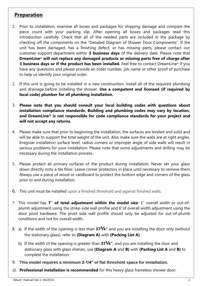
7. This model has 7” of total adjustment within the model size: 1” overall width or out-of-
plumb adjustment using the strike-side wall profile and 6”of overall width adjustment using the
door pivot hardware. The pivot side wall profile should only be adjusted for out-of-plumb
conditions and not for overall width.
8. a) If the width of the opening is less than 37¾” and you are installing the door only (without
the stationary glass), refer to (Diagram A) with (Packing List A).
b) If the width of the opening is greater than 37¼”, and you are installing the door and
stationary glass with glass shelves, use (Diagram A and B) with (Packing List A and B) to
complete the installation.
9. This model requires a minimum 2-1/4” of flat threshold space for installation.
10. Professional installation is recommended for this heavy glass frameless shower door.
“Allure” manual Ver 2 04/2016 3
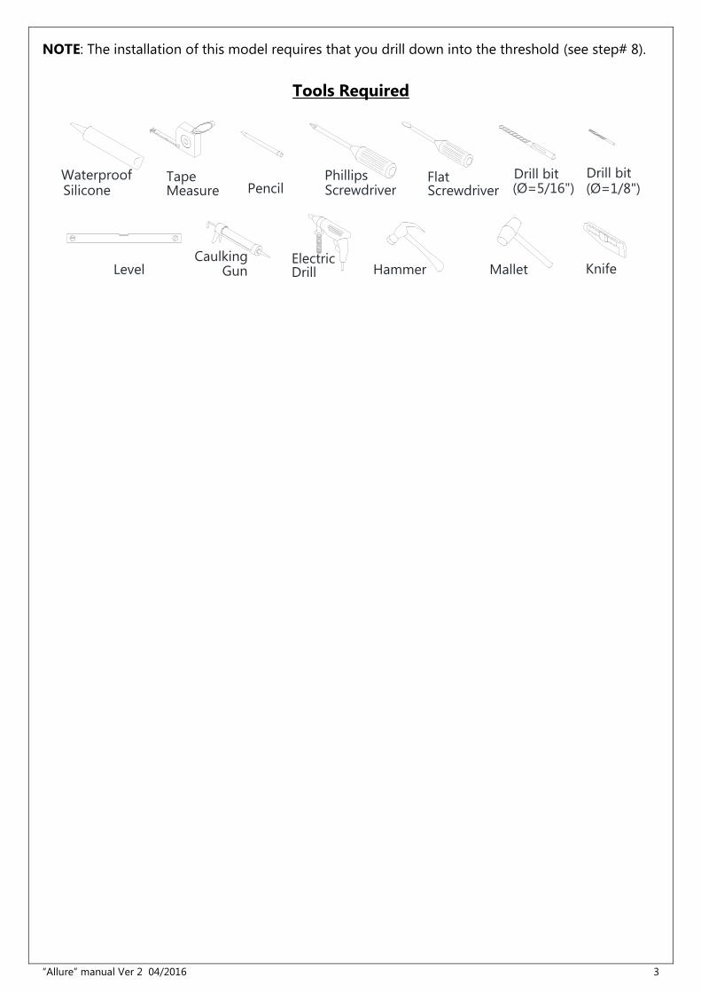
NOTE: The installation of this model requires that you drill down into the threshold (see step# 8).
Tools Required
Waterproof TapeMeasure Pencil Screwdriver
Phillips(Ø=5/16")Drill bit
Level GunCaulking
DrillElectric
Hammer Knife
(Ø=1/8")Drill bit
ScrewdriverFlat
Mallet
Silicone
“Allure” manual Ver 2 04/2016 4
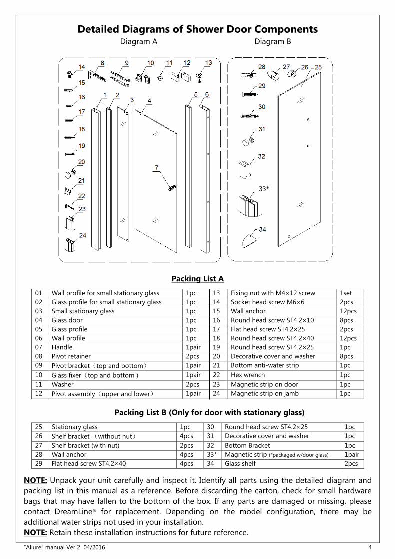
Detailed Diagrams of Shower Door Components
Diagram A Diagram B
Packing List A
01 Wall profile for small stationary glass 1pc 13 Fixing nut with M4×12 screw 1set
02 Glass profile for small stationary glass 1pc 14 Socket head screw M6×6 2pcs
03 Small stationary glass 1pc 15 Wall anchor 12pcs
04 Glass door 1pc 16 Round head screw ST4.2×10 8pcs
05 Glass profile 1pc 17 Flat head screw ST4.2×25 2pcs
06 Wall profile 1pc 18 Round head screw ST4.2×40 12pcs
07 Handle 1pair 19 Round head screw ST4.2×25 1pc
08 Pivot retainer 2pcs 20 Decorative cover and washer 8pcs
09 Pivot bracket(top and bottom) 1pair 21 Bottom anti-water strip 1pc
10 Glass fixer(top and bottom ) 1pair 22 Hex wrench 1pc
11 Washer 2pcs 23 Magnetic strip on door 1pc
12 Pivot assembly(upper and lower) 1pair 24 Magnetic strip on jamb 1pc
Packing List B (Only for door with stationary glass)
25 Stationary glass 1pc 30 Round head screw ST4.2×25 1pc
26 Shelf bracket (without nut) 4pcs 31 Decorative cover and washer 1pc
27 Shelf bracket (with nut) 2pcs 32 Bottom Bracket 1pc
28 Wall anchor 4pcs 33* Magnetic strip (*packaged w/door glass) 1pair
29 Flat head screw ST4.2×40 4pcs 34 Glass shelf 2pcs
NOTE: Unpack your unit carefully and inspect it. Identify all parts using the detailed diagram and
packing list in this manual as a reference. Before discarding the carton, check for small hardware
bags that may have fallen to the bottom of the box. If any parts are damaged or missing, please
contact DreamLine® for replacement. Depending on the model configuration, there may be
additional water strips not used in your installation.
NOTE: Retain these installation instructions for future reference.
33*
“Allure” manual Ver.2 04/2016 5
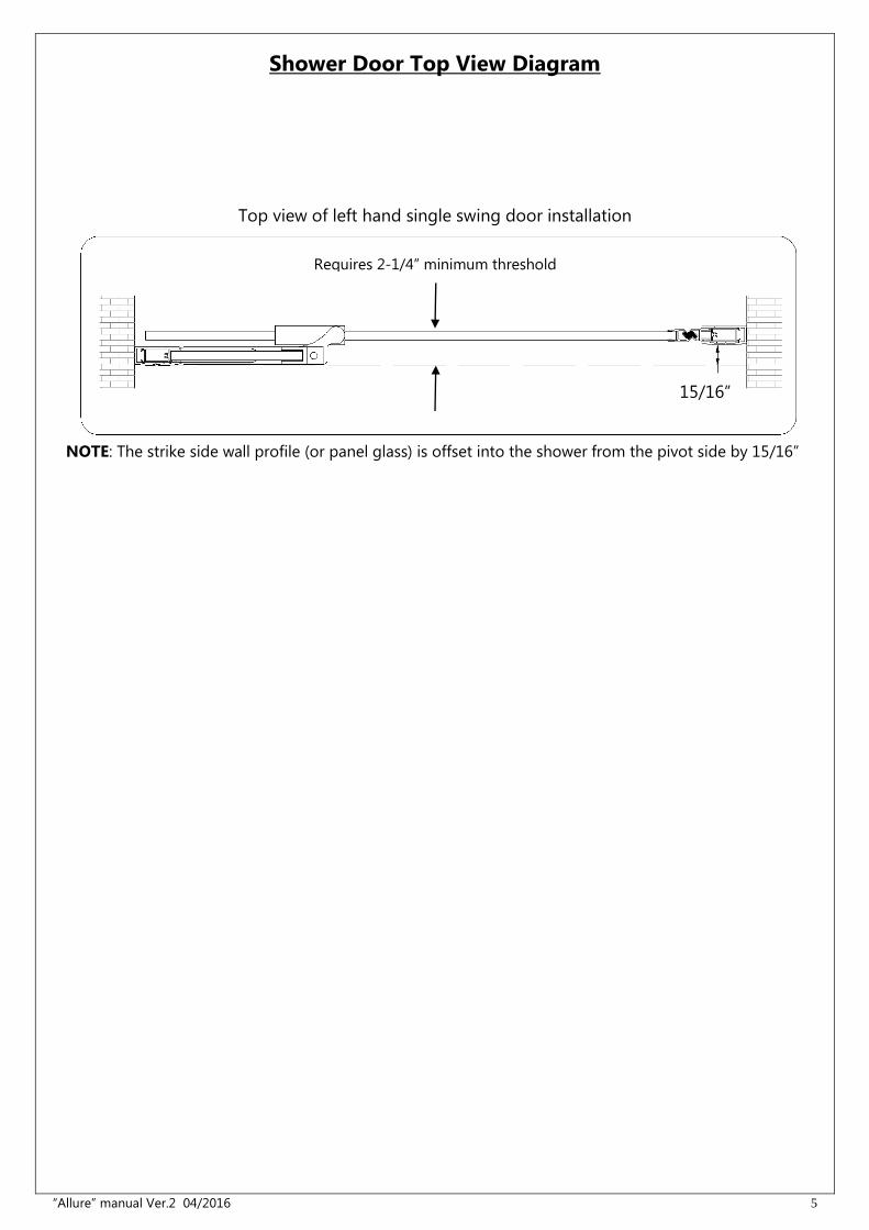
Shower Door Top View Diagram
15/16”
Requires 2-1/4” minimum threshold
NOTE: The strike side wall profile (or panel glass) is offset into the shower from the pivot side by 15/16”
Top view of left hand single swing door installation
“Allure” manual Ver.2 04/2016 6
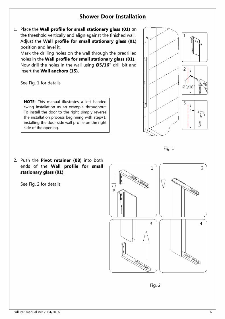
Shower Door Installation
1. Place the Wall profile for small stationary glass (01) on
the threshold vertically and align against the finished wall.
Adjust the Wall profile for small stationary glass (01)
position and level it.
Mark the drilling holes on the wall through the predrilled
holes in the Wall profile for small stationary glass (01).
Now drill the holes in the wall using Ø5/16” drill bit and
insert the Wall anchors (15).
See Fig. 1 for details
Fig. 1
2. Push the Pivot retainer (08) into both
ends of the Wall profile for small
stationary glass (01).
See Fig. 2 for details
Fig. 2
Ø5/16”
1
2
3
1
3
2
4
NOTE: This manual illustrates a left handed
swing installation as an example throughout.
To install the door to the right, simply reverse
the installation process beginning with step#1,
installing the door side wall profile on the right
side of the opening.
“Allure” manual Ver.2 04/2016 7
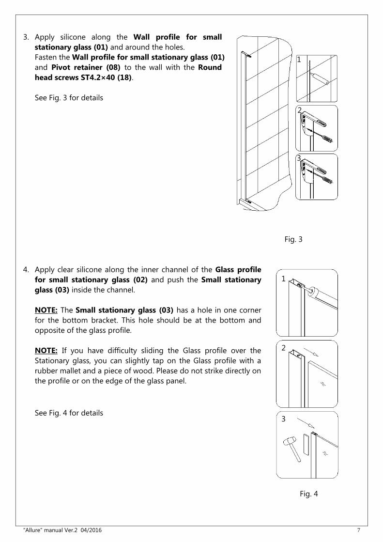
3. Apply silicone along the Wall profile for small
stationary glass (01) and around the holes.
Fasten the Wall profile for small stationary glass (01)
and Pivot retainer (08) to the wall with the Round
head screws ST4.2×40 (18).
See Fig. 3 for details
Fig. 3
4. Apply clear silicone along the inner channel of the Glass profile
for small stationary glass (02) and push the Small stationary
glass (03) inside the channel.
NOTE: The Small stationary glass (03) has a hole in one corner
for the bottom bracket. This hole should be at the bottom and
opposite of the glass profile.
NOTE: If you have difficulty sliding the Glass profile over the
Stationary glass, you can slightly tap on the Glass profile with a
rubber mallet and a piece of wood. Please do not strike directly on
the profile or on the edge of the glass panel.
See Fig. 4 for details
Fig. 4
1
2
3
1
2
3
“Allure” manual Ver.2 04/2016 8
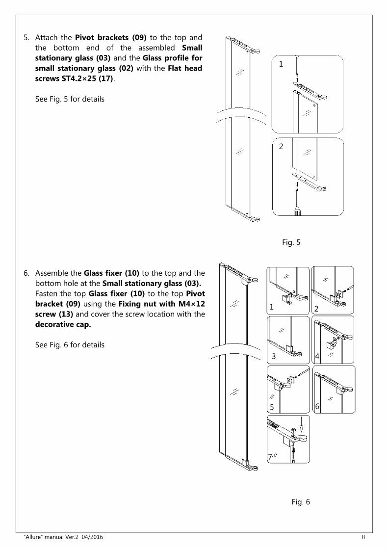
5. Attach the Pivot brackets (09) to the top and
the bottom end of the assembled Small
stationary glass (03) and the Glass profile for
small stationary glass (02) with the Flat head
screws ST4.2×25 (17).
See Fig. 5 for details
Fig. 5
6. Assemble the Glass fixer (10) to the top and the
bottom hole at the Small stationary glass (03).
Fasten the top Glass fixer (10) to the top Pivot
bracket (09) using the Fixing nut with M4×12
screw (13) and cover the screw location with the
decorative cap.
See Fig. 6 for details
Fig. 6
Fig. 6
2
3
1
2
1
3 4
5 6
7
2
“Allure” manual Ver.2 04/2016 9
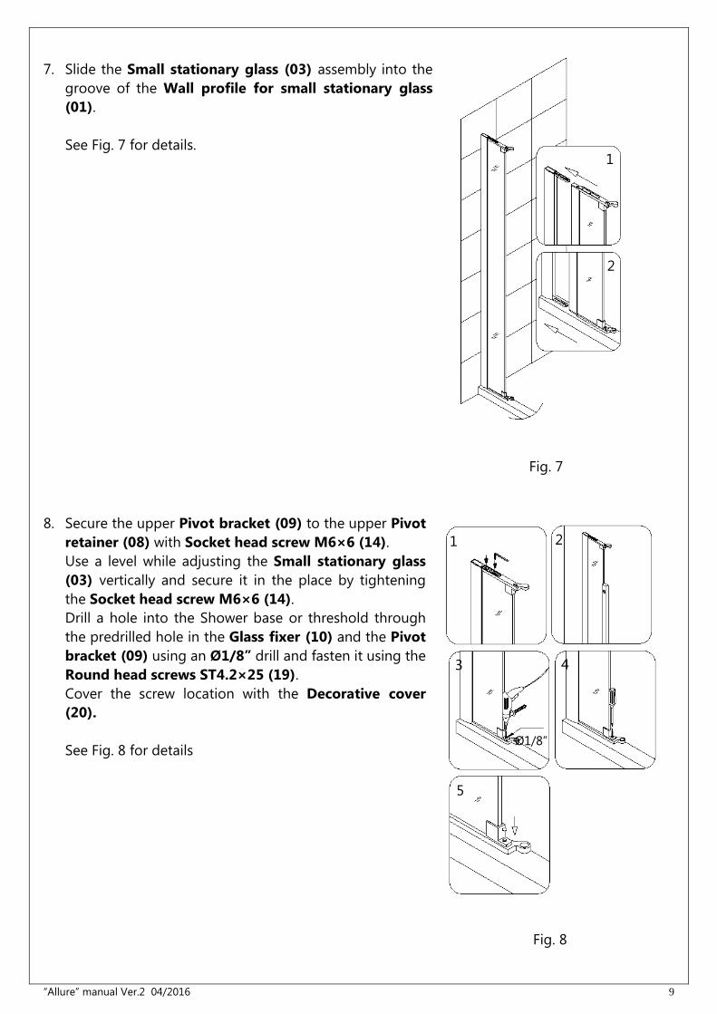
7. Slide the Small stationary glass (03) assembly into the
groove of the Wall profile for small stationary glass
(01).
See Fig. 7 for details.
Fig. 7
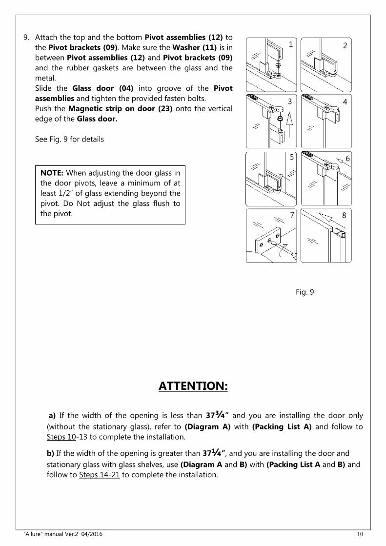
8. Secure the upper Pivot bracket (09) to the upper Pivot
retainer (08) with Socket head screw M6×6 (14).
Use a level while adjusting the Small stationary glass
(03) vertically and secure it in the place by tightening
the Socket head screw M6×6 (14).
Drill a hole into the Shower base or threshold through
the predrilled hole in the Glass fixer (10) and the Pivot
bracket (09) using an Ø1/8” drill and fasten it using the
Round head screws ST4.2×25 (19).
Cover the screw location with the Decorative cover
(20).
See Fig. 8 for details
Fig. 8
Ø1/8”
2
1
1
5
3 4
2
“Allure” manual Ver.2 04/2016 10
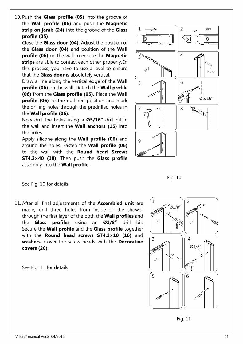
9. Attach the top and the bottom Pivot assemblies (12) to
the Pivot brackets (09). Make sure the Washer (11) is in
between Pivot assemblies (12) and Pivot brackets (09)
and the rubber gaskets are between the glass and the
metal.
Slide the Glass door (04) into groove of the Pivot
assemblies and tighten the provided fasten bolts.
Push the Magnetic strip on door (23) onto the vertical
edge of the Glass door.
See Fig. 9 for details
Fig. 9
ATTENTION:
a) If the width of the opening is less than 37¾” and you are installing the door only
(without the stationary glass), refer to (Diagram A) with (Packing List A) and follow to
Steps 10-13 to complete the installation.
b) If the width of the opening is greater than 37¼”, and you are installing the door and
stationary glass with glass shelves, use (Diagram A and B) with (Packing List A and B) and
follow to Steps 14-21 to complete the installation.
1
3 4
2
7 8
5 6
NOTE: When adjusting the door glass in
the door pivots, leave a minimum of at
least 1/2” of glass extending beyond the
pivot. Do Not adjust the glass flush to
the pivot.
“Allure” manual Ver.2 04/2016 11
10. Push the Glass profile (05) into the groove of
the Wall profile (06) and push the Magnetic
strip on jamb (24) into the groove of the Glass
profile (05).
Close the Glass door (04). Adjust the position of
the Glass door (04) and position of the Wall
profile (06) on the wall to ensure the Magnetic
strips are able to contact each other properly. In
this process, you have to use a level to ensure
that the Glass door is absolutely vertical.
Draw a line along the vertical edge of the Wall
profile (06) on the wall. Detach the Wall profile
(06) from the Glass profile (05). Place the Wall
profile (06) to the outlined position and mark
the drilling holes through the predrilled holes in
the Wall profile (06).
Now drill the holes using a Ø5/16” drill bit in
the wall and insert the Wall anchors (15) into
the holes.
Apply silicone along the Wall profile (06) and
around the holes. Fasten the Wall profile (06)
to the wall with the Round head Screws
ST4.2×40 (18). Then push the Glass profile
assembly into the Wall profile.
Fig. 10
See Fig. 10 for details
11. After all final adjustments of the Assembled unit are
made, drill three holes from inside of the shower
through the first layer of the both the Wall profiles and
the Glass profiles using an Ø1/8” drill bit.
Secure the Wall profile and the Glass profile together
with the Round head screws ST4.2×10 (16) and
washers. Cover the screw heads with the Decorative
covers (20).
See Fig. 11 for details
Fig. 11
1 2
3 4
5 6
7 8
Ø5/16”
Ø1/8”
Ø1/8”
1
3 4
5
2
6
9
Inside
Inside
“Allure” manual Ver.2 04/2016 12
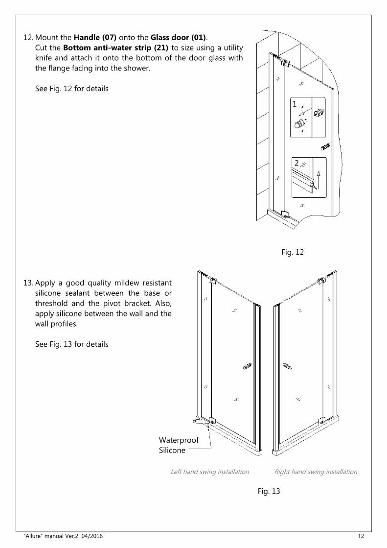
12. Mount the Handle (07) onto the Glass door (01).
Cut the Bottom anti-water strip (21) to size using a utility
knife and attach it onto the bottom of the door glass with
the flange facing into the shower.
See Fig. 12 for details
Fig. 12
13. Apply a good quality mildew resistant
silicone sealant between the base or
threshold and the pivot bracket. Also,
apply silicone between the wall and the
wall profiles.
See Fig. 13 for details
Fig. 13
Waterproof
Silicone
1
2
Left hand swing installation
Right hand swing installation
“Allure” manual Ver.2 04/2016 13
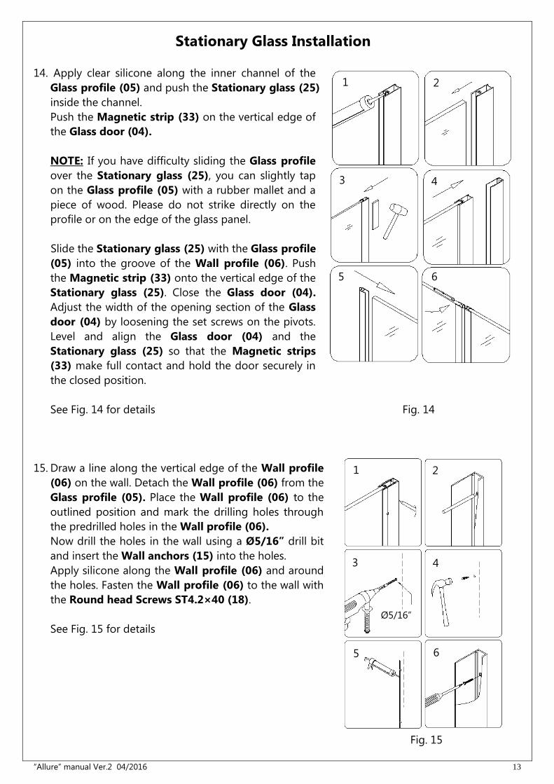
Stationary Glass Installation
14. Apply clear silicone along the inner channel of the
Glass profile (05) and push the Stationary glass (25)
inside the channel.
Push the Magnetic strip (33) on the vertical edge of
the Glass door (04).
NOTE: If you have difficulty sliding the Glass profile
over the Stationary glass (25), you can slightly tap
on the Glass profile (05) with a rubber mallet and a
piece of wood. Please do not strike directly on the
profile or on the edge of the glass panel.
Slide the Stationary glass (25) with the Glass profile
(05) into the groove of the Wall profile (06). Push
the Magnetic strip (33) onto the vertical edge of the
Stationary glass (25). Close the Glass door (04).
Adjust the width of the opening section of the Glass
door (04) by loosening the set screws on the pivots.
Level and align the Glass door (04) and the
Stationary glass (25) so that the Magnetic strips
(33) make full contact and hold the door securely in
the closed position.
See Fig. 14 for details Fig. 14
15. Draw a line along the vertical edge of the Wall profile
(06) on the wall. Detach the Wall profile (06) from the
Glass profile (05). Place the Wall profile (06) to the
outlined position and mark the drilling holes through
the predrilled holes in the Wall profile (06).
Now drill the holes in the wall using a Ø5/16” drill bit
and insert the Wall anchors (15) into the holes.
Apply silicone along the Wall profile (06) and around
the holes. Fasten the Wall profile (06) to the wall with
the Round head Screws ST4.2×40 (18).
See Fig. 15 for details
1 2
6 5
3 4
1
3
5
4
6
2
Ø5/16”
Fig. 15
“Allure” manual Ver.2 04/2016 14
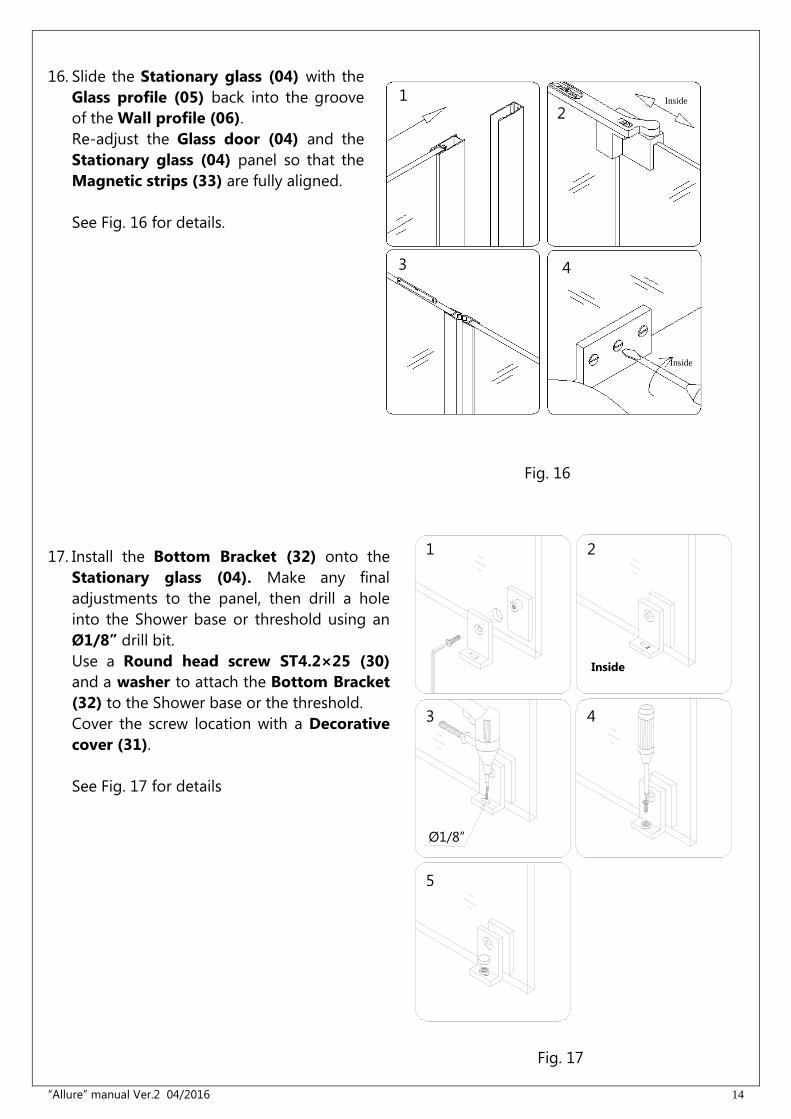
16. Slide the Stationary glass (04) with the
Glass profile (05) back into the groove
of the Wall profile (06).
Re-adjust the Glass door (04) and the
Stationary glass (04) panel so that the
Magnetic strips (33) are fully aligned.
See Fig. 16 for details.
Fig. 16
17. Install the Bottom Bracket (32) onto the
Stationary glass (04). Make any final
adjustments to the panel, then drill a hole
into the Shower base or threshold using an
Ø1/8” drill bit.
Use a Round head screw ST4.2×25 (30)
and a washer to attach the Bottom Bracket
(32) to the Shower base or the threshold.
Cover the screw location with a Decorative
cover (31).
See Fig. 17 for details
Fig. 17
1 2
3 4
3
2 1
4
Ø1/8”
5
Inside
Inside
Inside
“Allure” manual Ver.2 04/2016 15
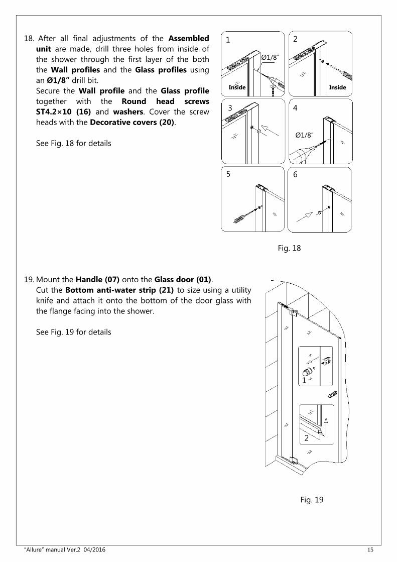
18. After all final adjustments of the Assembled
unit are made, drill three holes from inside of
the shower through the first layer of the both
the Wall profiles and the Glass profiles using
an Ø1/8” drill bit.
Secure the Wall profile and the Glass profile
together with the Round head screws
ST4.2×10 (16) and washers. Cover the screw
heads with the Decorative covers (20).
See Fig. 18 for details
Fig. 18
19. Mount the Handle (07) onto the Glass door (01).
Cut the Bottom anti-water strip (21) to size using a utility
knife and attach it onto the bottom of the door glass with
the flange facing into the shower.
See Fig. 19 for details
Fig. 19
1 2
3 4
5 6
Ø1/8”
1
2
Ø1/8”
Inside Inside
“Allure” manual Ver.2 04/2016 16
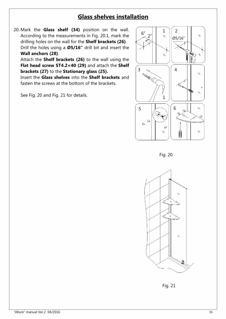
Glass shelves installation
20. Mark the Glass shelf (34) position on the wall.
According to the measurements in Fig. 20.1, mark the
drilling holes on the wall for the Shelf brackets (26).
Drill the holes using a Ø5/16” drill bit and insert the
Wall anchors (28).
Attach the Shelf brackets (26) to the wall using the
Flat head screw ST4.2×40 (29) and attach the Shelf
brackets (27) to the Stationary glass (25).
Insert the Glass shelves into the Shelf brackets and
fasten the screws at the bottom of the brackets.
See Fig. 20 and Fig. 21 for details.
Fig. 20
Fig. 21
2
4 3
5 6
1
1
2” 6”
Ø5/16”
“Allure” manual Ver.2 04/2016 17
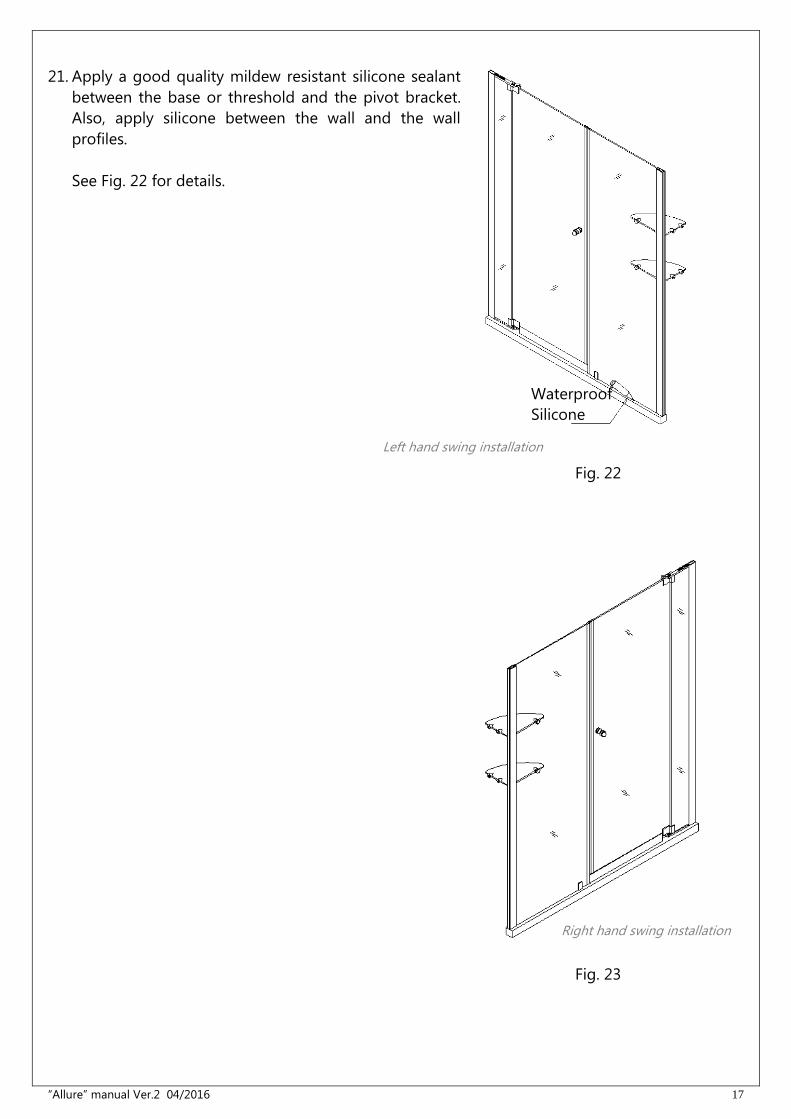
21. Apply a good quality mildew resistant silicone sealant
between the base or threshold and the pivot bracket.
Also, apply silicone between the wall and the wall
profiles.
See Fig. 22 for details.
Fig. 22
Fig. 23
Waterproof
Silicone
Left hand swing installation
Right hand swing installation
“Allure” manual Ver.2 04/2016 18
Product Maintenance
BASES and BACKWALLS: To ensure long lasting life for your acrylic back walls: wipe them off
after each use with a soft cloth. To clean the acrylic back walls use non-abrasive sprays or
cream based cleaners. Avoid the use of aerosol spray cleaners. Never use abrasive cleansers,
metal brushes or scrapers that could scratch or dull the surface.
GLASS: To ensure long lasting life for your glass shower products: wipe them off after each use
with a soft cloth. Rinse and wipe off the glass using either a soft cloth or a squeegee to prevent
soap buildup and water spots (Hard water can etch the surface of the glass over time if left to
dry). To prevent scratching the surface: never use abrasive cleaners or cleaning products that
contain scouring agents. Never use bristle brushes or abrasive sponges that may scratch the
surface.
HARDWARE: To ensure a long lasting finish: wipe off the metal parts after each use with a soft
cloth. Do not use abrasive cleaners or cleaning products containing ammonia, bleach or acid. If
accidentally used, rinse the surface as soon as possible to prevent damage to the finish
(peeling or corrosion). After cleaning the polished finishes, rinse thoroughly and wipe dry with
soft cloth. Clean stainless steel surfaces at least once a week. When applying stainless steel
cleaner or polish to stainless steel hardware, work with (not across) the grain. Never use an
abrasive sponge or cloth, steel wool or wired brush as these may permanently scratch the
surfaces.

“Allure” manual Ver.2 04/2016 19
TEL: 866-731-2244
FAX: 866-857-3638
DREAMLINE.COM
For more information on DreamLine® Shower Doors and Enclosures please visit DreamLine.com