drilled shafts: design, construction, qa/qc …€¦ · · 2018-05-08– o-cell / sensors (only...
TRANSCRIPT

DRILLED SHAFTS: DESIGN,
CONSTRUCTION, QA/QC TESTING
Vishal B. Patel, M.S.C.E., P.E.
Sebastian Lobo-Guerrero, Ph.D., P.E.

Outline
• Recent AASHTO/FHWA changes in design equations � QA/QC impact
• Construction: drilling Tools / machines
• Instrumentation for drilling (QA/QC)
• Testing (QA/QC) constructed shaft


Ultimate side friction (example if controlled by 3 ksi concrete)
Design Equations: the “old” vs new
Weight
Side friction
End bearing
AASHTO 2012 and earlier
AASHTO 2014
qs= 19.7 ksf
qs= 30.3 ksf
New value is 1.54 times the old!

End bearing
Weight
Side friction
End bearing
- No change in equation, allows using combination
of end bearing and side friction
- More State DOTs allowing this combination
Displacement
Load
Side friction,
residual after
approx. 0.4-0.5”
End bearing
“never” peaks

- New equations require rock socket with “clean” side
walls without the need of artificial roughening
- Does not apply if: walls show smearing, rapid
deterioration or collapse, and/or require temporary
support/pre-grouting
- If using end bearing: clean up procedure to be
specified to ensure removal of sediments/loose
material
� Construction QA/QC is a critical item!!!!

Drilling Tools - Augers
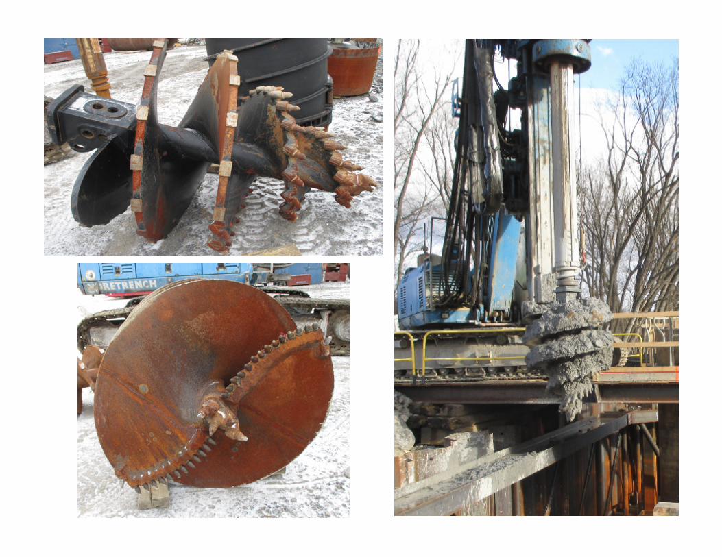

Down Hole Hammer

Machines


Casing

Reinforcement

Grouting

Traditional QA/QC items to record:
– Geometry (length, diameter)
– Elevations (working, bottom of Cap, bottom of shaft)
– Materials requirements (reinforcements / grout)
– Concrete: slump flow, air content, temperature, penetration test, UC strength, etc. � every 50 CY
– Advance / Drilling rate (ft/min)
– Spoils (material type vs. boring logs / design)
– Plumbness of shaft
– Spoil control
– Cleanliness at bottom of shaft
Well established ASTM tests and requirements

Slump (J-ring):
ASTM C1621

Instrumentation (QA/QC) during
Drilling
–Sonicaliper: 3D geometry
–MiniSID : quality of bottom of the shaft
–Down hole camera (visual inspection):
quality of side walls of the shaft

Sonicaliper: 3D geometry


Miniature Drilled Shaft Inspection
Device (MiniSID)

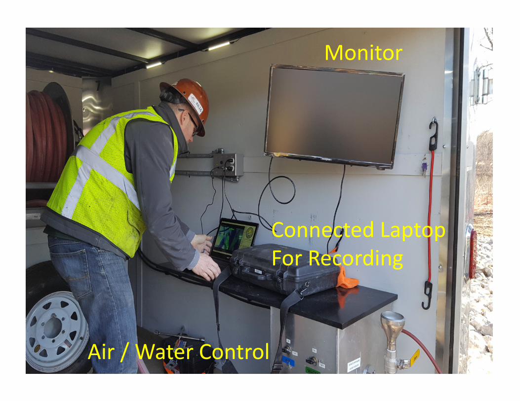
Monitor
Air / Water Control
Connected Laptop
For Recording

Mini SID - Looking from below (camera and depth
gage)
CameraAir Hose
Air Hose
Sediment Depth Gage

Sample
Reading On
Monitor
– 4 to 5 areas
– Based on specification, for
example…
• 50% lower than ½ or ¼ inch
• Max. lower than 1 or ½ inch

Cleaning the
Shaft

Down Hole Camera
Perfect above water, and below clear water


Testing Constructed Shaft
– Crosshole Sonic Logging (CSL)
–Thermal Integrity Profiler (TIP)
–Concrete coring
– O-Cell / Sensors (only for test shaft)

CSL
- Assesses concrete integrity by sending ultrasonic
pulses through the drilled shaft from one access tube
to another
- Transmitter and receiver probes are placed at the
bottom of the access tubes and then slowly raised
(one profile/ points approx. every 2”)
- Typically 1 probe per foot of drilled shaft dimeter

CSL Pipes:
typically steel
or PVC
PDI/GRL Eng.


ASTM D6760 - 16
Standard Test Method for Integrity Testing of Concrete
Deep Foundations by Ultrasonic Crosshole Testing


Thermal Integrity Profile (TIP)
- During curing: system measures concrete
temperatures using embed cables
- Thermal Acquisition Ports (TAPs) connected to
the ThermalWire®: store temperature data
- Cement hydrates during curing process:
generated heat increases temperature inside
the shaft

Attached to CSL
tubes
Attached to rebar
Sensors uniformly spaced


- Shaft radius vs depth: calculated based on
measured average peak temperature
- Integrity: based on measured concrete
volume input and the average peak
temperature
- If measured average temperature vs depth
is consistent: uniform shape and quality

- Bulges: localized increases in average temp.
- Poor concrete quality or necking: localized
decreases in average temperature
- Areas of soil intrusion/inclusion: lower local
temperatures.
- ASTM D7949 – 14 Standard Test Methods for
Thermal Integrity Profiling of Concrete Deep
Foundations

Roll off
effect
Roll off
effect


Advantage vs. CSL:
“outside the rebar”


Concrete Coring
- Intended areas:

Besides visual observation, option to perform unconfined
compression testing

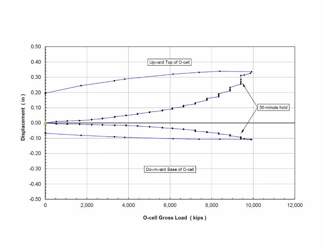
O-cell Load Test (Bidirectional load test)
Weight
Side friction
Weight
Side friction
Load cell
End bearing

O-cell
Upper part of shaft
Lower part of shaft


Complete shaft
instrumentation for load
and displacement:
- Strain gages/ LWDTs
- Tell tales
- etc

Selecting the right
dimensions and the right
cell:
- Use ultimate Geotech
side shear and end
bearing stresses
- Load > Expected
resistance
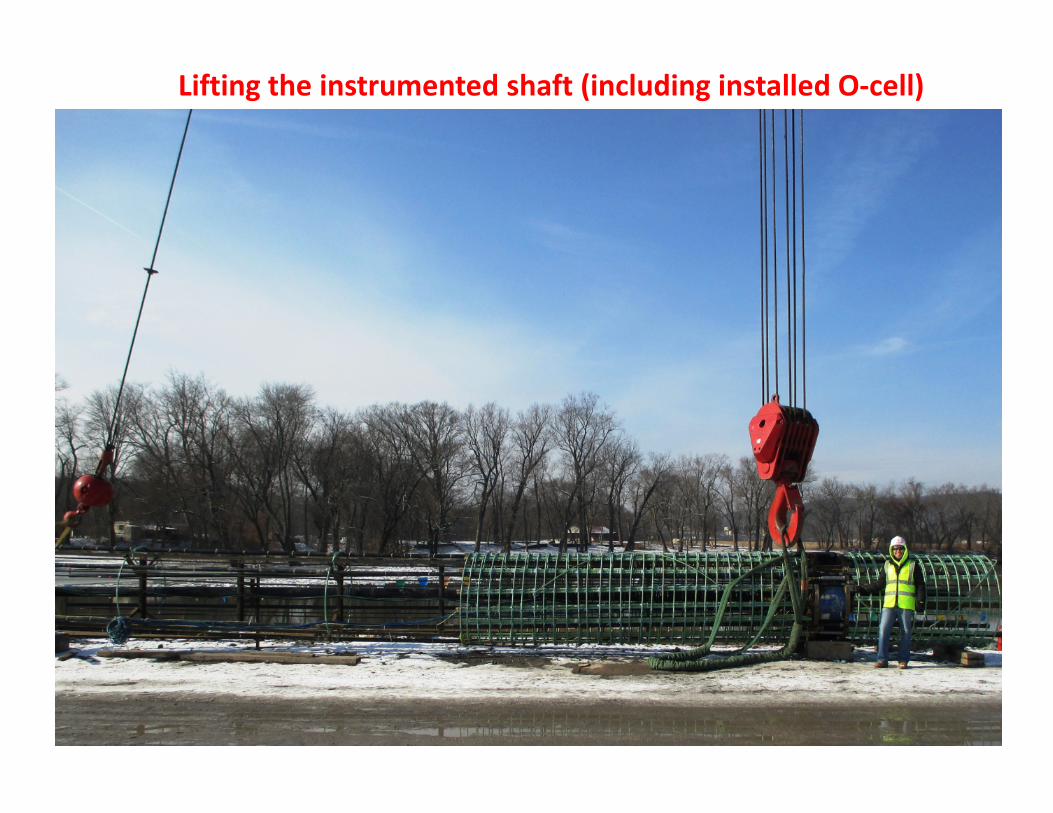
Lifting the instrumented shaft (including installed O-cell)

Upper part
of shaft
Lower part
of shaft
O-cell


Acknowledgements