driver manual fs-8700-19 metasys® n2 by johnson controls
TRANSCRIPT
Driver Version: 1.04
Document Revision: 3
A Sierra Monitor Company
APPLICABILITY & EFFECTIVITY
Effective for all systems manufactured after March 2011
Driver Manual
(Supplement to the FieldServer Instruction Manual)
FS-8700-19 Metasys® N2 by Johnson Controls
FS-8700-19 Metasys® N2 by JCI Driver Manual Table of Contents
FieldServer Technologies 1991 Tarob Court Milpitas, California 95035 USA Web: www.fieldserver.com Tel: (408) 262 2299 Fax: (408) 262 2269 Toll Free: (888) 509 1970 email: [email protected]
TABLE OF CONTENTS
1 Metasys® N2 by Johnson Controls Description ............................................................................................... 4
2 Driver Scope of Supply ................................................................................................................................... 4
2.1 Supplied by FieldServer Technologies for this driver ..................................................................................... 4
2.2 Provided by the Supplier of 3rd
Party Equipment .......................................................................................... 4
2.2.1 Hardware ............................................................................................................................................... 4
2.2.2 Required 3rd
Party Software ................................................................................................................... 4
2.2.3 Required 3rd
Party Configuration ........................................................................................................... 4
3 Hardware Connections ................................................................................................................................... 5
3.1 Hardware Connection Tips / Hints ................................................................................................................. 5
4 Data Array Parameters ................................................................................................................................... 6
5 Configuring the FieldServer as a Metasys® N2 Client ...................................................................................... 7
5.1 Client Side Connection Parameters ............................................................................................................... 7
5.2 Client Side Node Parameters ......................................................................................................................... 8
5.3 Client Side Map Descriptor Parameters ......................................................................................................... 8
5.3.1 FieldServer Related Map Descriptor Parameters ................................................................................... 8
5.3.2 Driver Specific Map Descriptor Parameters ........................................................................................... 9
5.3.3 Timing Parameters ............................................................................................................................... 10
5.3.4 Map Descriptor Example – N2Open ..................................................................................................... 11
5.3.5 Map Descriptor Example - Client Side COS_READ Map Descriptor for Analog Input point.................. 11
5.3.6 Map Descriptor Example - VMA ........................................................................................................... 12
5.3.7 Map Descriptor Example - DX9100 ...................................................................................................... 12
6 Configuring the FieldServer as a Metasys® N2 Server ................................................................................... 13
6.1 Server Side Connection Paramaters ............................................................................................................ 13
6.2 Server Side Node Parameters ...................................................................................................................... 14
6.3 Server Side Map Descriptor Parameters ...................................................................................................... 14
6.3.1 FieldServer Specific Map Descriptor Parameters ................................................................................. 14
6.3.2 Driver Specific Map Descriptor Parameters ......................................................................................... 14
6.3.3 N2Open Specific Map Descriptor Parameters ...................................................................................... 15
6.3.4 Map Descriptor Example ...................................................................................................................... 16
6.3.5 Map Descriptor Example – N2 Open Server Side Map Descriptor for Analog Input point ................... 16
Appendix A. Useful Features ................................................................................................................................ 17
Appendix A.1. Writing to DX9100 Binary Outputs ................................................................................................... 17
Appendix A.2. Managing Analog Inputs and Outputs for DX9100........................................................................... 18
Appendix A.3. Using Override and Release – N2Open ............................................................................................ 18
Appendix A.4. Using Change of State (COS) – N2Open ........................................................................................... 19
Appendix A.4.1. Important Note on COS Operation in N2Open ....................................................................... 19
Appendix A.5. Read/Write All Attributes – N2 Open ............................................................................................... 19
Appendix A.5.1. Map Descriptor Example 1 - Read all attributes for an Analog Input. ................................... 20
Appendix A.5.2. Map Descriptor Example 2 - Read all attributes for an Binary Input. .................................... 20
Appendix A.5.3. Map Descriptor Example 3 - Read all attributes for an Analog Output. ................................ 20
Appendix A.5.4. Map Descriptor Example 4 - Read all attributes for a Digital Output. ................................... 20
Appendix A.5.5. Write All Attributes (Applicable only to Data_Type AI,DI. AO, DO). ....................................... 20
Appendix A.5.6. Map Descriptor Example 5 - Write all attributes for an Analog Input. .................................. 21
FS-8700-19 Metasys® N2 by JCI Driver Manual Table of Contents
FieldServer Technologies 1991 Tarob Court Milpitas, California 95035 USA Web: www.fieldserver.com Tel: (408) 262 2299 Fax: (408) 262 2269 Toll Free: (888) 509 1970 email: [email protected]
Appendix A.5.7. Map Descriptor Example 6 - Write all attributes for an Binary Input. ................................... 21
Appendix A.5.8. Map Descriptor Example 7 - Write all attributes for an Analog Output. ............................... 21
Appendix A.5.9. Map Descriptor Example 8 - Write all attributes for an Analog Input. .................................. 22
Appendix A.6. Write Internal Parameters – N2 Open ............................................................................................. 22
Appendix A.7. ADI, ADF and BD types: using the “Driver” Data_Type and MN2_Type fields ................................. 23
Appendix A.8. Using Override and Release - VMA .................................................................................................. 23
Appendix A.9. Setting up FS-B20 for RS-485 ............................................................................................................ 24
Appendix A.9.1. Jumper Settings: ..................................................................................................................... 24
Appendix A.9.2. Hardware connections ........................................................................................................... 26
Appendix A.9.3. Configuration Settings............................................................................................................ 26
Appendix B. Troubleshooting tips ........................................................................................................................ 27
Appendix B.1. Offline Behavior ................................................................................................................................ 27
Appendix B.2. Tip on Overrides ............................................................................................................................... 27
Appendix B.3. MN2Open Test Tool ......................................................................................................................... 27
Appendix C. Reference ......................................................................................................................................... 28
Appendix C.1. Error Messages ................................................................................................................................. 28
Appendix C.2. Listing of Supported Attributes – N2Open ....................................................................................... 28
Appendix C.3. Metasys® DX9100 Memory Map ...................................................................................................... 29
FS-8700-19 Metasys® N2 by JCI Driver Manual Page 4 of 34
FieldServer Technologies 1991 Tarob Court Milpitas, California 95035 USA Web: www.fieldserver.com Tel: (408) 262 2299 Fax: (408) 262 2269 Toll Free: (888) 509 1970 email: [email protected]
1 METASYS® N2 BY JOHNSON CONTROLS DESCRIPTION
The Metasys® N21 by Johnson Controls network supports communications with a diverse range of devices. Many
N2 compatible devices use their own version of the protocol and care must be taken to ensure that the device of
interest is covered by the FieldServer implementation.
At present the FieldServer Metasys® N2 driver will support communications with the following devices or classes of
devices when acting as a Client:
N2Open-compliant devices. N2Open is a published N2-compatible protocol enabling 3rd
party device vendors
to integrate with N2.
VMA 1400 series (with restrictions)
DX9100 and XT9100
When acting as a Server the FieldServer Metasys® N2 driver can emulate an N2Open device only.
FieldServer Mode Nodes Comments
Client 1
Only 1 client node allowed on Multidrop systems. Can communicate with:
N2Open
VMA 1400 series (AI,BI,AO,BO and custom types)
DX9100 / XT9100
Server 255
2 DRIVER SCOPE OF SUPPLY
2.1 Supplied by FieldServer Technologies for this driver
FieldServer Technologies PART # Description
FS-8917-16 RJ45 to terminal connector cable.
2.2 Provided by the Supplier of 3 rd Party Equipment
2.2.1 Hardware
PART # DESCRIPTION
Metasys® NCU or other device
2.2.2 Required 3 r d Party Software
Depending on application, JCI software may be necessary
2.2.3 Required 3 r d Party Configuration
Depending on application, third party devices may need configuration
1 Metasys® and N2OPEN as used in this document are a trademarks of Johnson Controls Inc
FS-8700-19 Metasys® N2 by JCI Driver Manual Page 5 of 34
FieldServer Technologies 1991 Tarob Court Milpitas, California 95035 USA Web: www.fieldserver.com Tel: (408) 262 2299 Fax: (408) 262 2269 Toll Free: (888) 509 1970 email: [email protected]
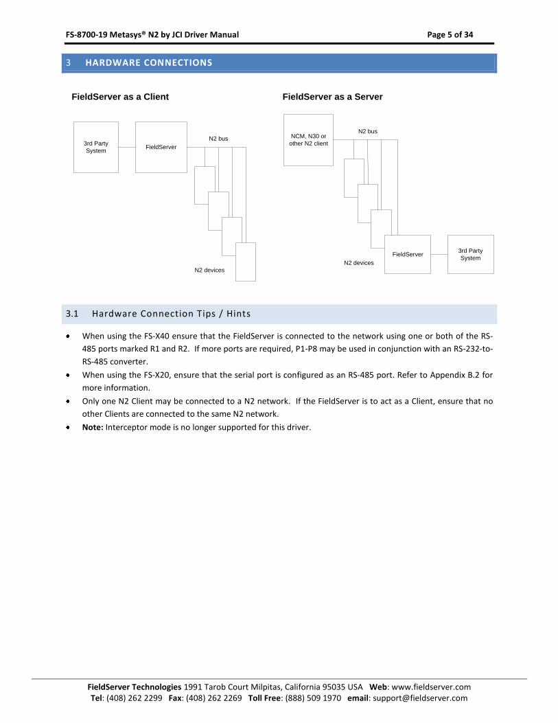
3 HARDWARE CONNECTIONS
FieldServer as a Server
NCM, N30 or
other N2 client
3rd Party
SystemFieldServer
N2 bus
N2 devices
FieldServer as a Client
FieldServer
N2 bus
N2 devices
3rd Party
System
3.1 Hardware Connection Tips / Hints
When using the FS-X40 ensure that the FieldServer is connected to the network using one or both of the RS-
485 ports marked R1 and R2. If more ports are required, P1-P8 may be used in conjunction with an RS-232-to-
RS-485 converter.
When using the FS-X20, ensure that the serial port is configured as an RS-485 port. Refer to Appendix B.2 for
more information.
Only one N2 Client may be connected to a N2 network. If the FieldServer is to act as a Client, ensure that no
other Clients are connected to the same N2 network.
Note: Interceptor mode is no longer supported for this driver.
FS-8700-19 Metasys® N2 by JCI Driver Manual Page 6 of 34
FieldServer Technologies 1991 Tarob Court Milpitas, California 95035 USA Web: www.fieldserver.com Tel: (408) 262 2299 Fax: (408) 262 2269 Toll Free: (888) 509 1970 email: [email protected]
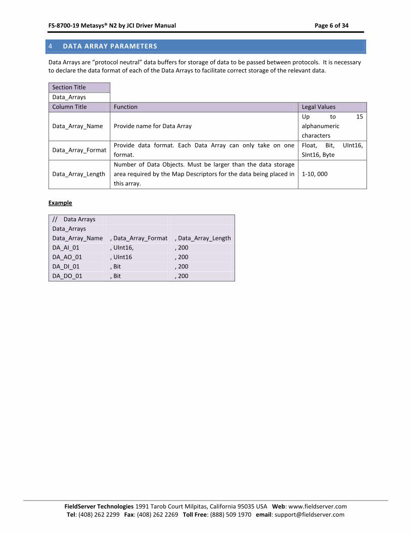
4 DATA ARRAY PARAMETERS
Data Arrays are “protocol neutral” data buffers for storage of data to be passed between protocols. It is necessary to declare the data format of each of the Data Arrays to facilitate correct storage of the relevant data.
Section Title
Data_Arrays
Column Title Function Legal Values
Data_Array_Name Provide name for Data Array
Up to 15
alphanumeric
characters
Data_Array_Format Provide data format. Each Data Array can only take on one
format.
Float, Bit, UInt16,
SInt16, Byte
Data_Array_Length
Number of Data Objects. Must be larger than the data storage
area required by the Map Descriptors for the data being placed in
this array.
1-10, 000
Example
// Data Arrays
Data_Arrays
Data_Array_Name , Data_Array_Format , Data_Array_Length
DA_AI_01 , UInt16, , 200
DA_AO_01 , UInt16 , 200
DA_DI_01 , Bit , 200
DA_DO_01 , Bit , 200
FS-8700-19 Metasys® N2 by JCI Driver Manual Page 7 of 34
FieldServer Technologies 1991 Tarob Court Milpitas, California 95035 USA Web: www.fieldserver.com Tel: (408) 262 2299 Fax: (408) 262 2269 Toll Free: (888) 509 1970 email: [email protected]
5 CONFIGURING THE FIELDSERVER AS A METASYS® N2 CLIENT
For a detailed discussion on FieldServer configuration, please refer to the FieldServer Configuration manual. The
information that follows describes how to expand upon the factory defaults provided in the configuration files
included with the FieldServer (See “.csv” sample files provided with the FieldServer).
This section documents and describes the parameters necessary for configuring the FieldServer to communicate
with a Metasys® N2 Server.
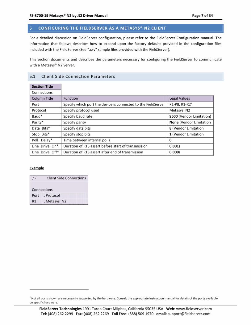
5.1 Client Side Connection Parameters
Section Title
Connections
Column Title Function Legal Values
Port Specify which port the device is connected to the FieldServer P1-P8, R1-R22
Protocol Specify protocol used Metasys_N2
Baud* Specify baud rate 9600 (Vendor Limitation)
Parity* Specify parity None (Vendor Limitation
Data_Bits* Specify data bits 8 (Vendor Limitation
Stop_Bits* Specify stop bits 1 (Vendor Limitation
Poll _Delay* Time between internal polls 0
Line_Drive_On* Duration of RTS assert before start of transmission 0.001s
Line_Drive_Off* Duration of RTS assert after end of transmission 0.000s
Example
// Client Side Connections
Connections
Port , Protocol
R1 , Metasys_N2
2 Not all ports shown are necessarily supported by the hardware. Consult the appropriate Instruction manual for details of the ports available on specific hardware.
FS-8700-19 Metasys® N2 by JCI Driver Manual Page 8 of 34
FieldServer Technologies 1991 Tarob Court Milpitas, California 95035 USA Web: www.fieldserver.com Tel: (408) 262 2299 Fax: (408) 262 2269 Toll Free: (888) 509 1970 email: [email protected]
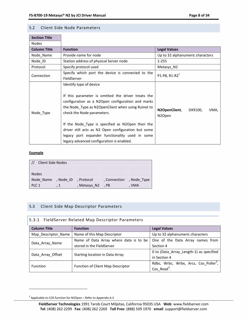
5.2 Client Side Node Parameters
Section Title
Nodes
Column Title Function Legal Values
Node_Name Provide name for node Up to 32 alphanumeric characters
Node_ID Station address of physical Server node 1-255
Protocol Specify protocol used Metasys_N2
Connection Specify which port the device is connected to the
FieldServer P1-P8, R1-R2
1
Node_Type
Identify type of device
If this parameter is omitted the driver treats the
configuration as a N2Open configuration and marks
the Node_Type as N2OpenClient when using Ruinet to
check the Node parameters.
If the Node_Type is specified as N2Open then the
driver still acts as N2 Open configuration but some
legacy port expander functionality used in some
legacy advanced configuration is enabled.
N2OpenClient, DX9100, VMA,
N2Open
Example
// Client Side Nodes
Nodes
Node_Name , Node_ID , Protocol , Connection , Node_Type
PLC 1 , 1 , Metasys_N2 , P8 , VMA
5.3 Client Side Map Descriptor Parameters
5.3.1 FieldServer Related Map Descriptor Parameters
Column Title Function Legal Values
Map_Descriptor_Name Name of this Map Descriptor Up to 32 alphanumeric characters
Data_Array_Name Name of Data Array where data is to be
stored in the FieldServer
One of the Data Array names from
Section 4
Data_Array_Offset Starting location in Data Array 0 to (Data_Array_Length-1) as specified
in Section 4
Function Function of Client Map Descriptor Rdbc, Wrbc, Wrbx, Arcs, Cos_Poller
3,
Cos_Read3.
3 Applicable to COS function for N2Open – Refer to Appendix A.3
FS-8700-19 Metasys® N2 by JCI Driver Manual Page 9 of 34
FieldServer Technologies 1991 Tarob Court Milpitas, California 95035 USA Web: www.fieldserver.com Tel: (408) 262 2299 Fax: (408) 262 2269 Toll Free: (888) 509 1970 email: [email protected]
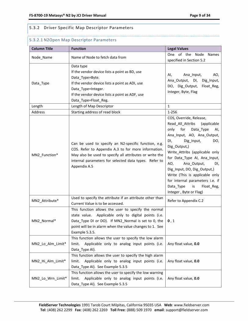
5.3.2 Driver Specific Map Descriptor Parameters
5.3.2.1 N2Open Map Descriptor Parameters
Column Title Function Legal Values
Node_Name Name of Node to fetch data from One of the Node Names
specified in Section 5.2
Data_Type
Data type
If the vendor device lists a point as BD, use
Data_Type=Byte.
If the vendor device lists a point as ADI, use
Data_Type=Integer.
If the vendor device lists a point as ADF, use
Data_Type=Float_Reg.
AI, Ana_Input, AO,
Ana_Output, DI, Dig_Input,
DO, Dig_Output, Float_Reg,
Integer, Byte, Flag
Length Length of Map Descriptor 1
Address Starting address of read block 1-256
MN2_Function*
Can be used to specify an N2-specific function, e.g.
COS. Refer to Appendix A.3 to for more information.
May also be used to specify all attributes or write the
internal parameters for selected data types. Refer to
Appendix A.5
COS, Override, Release,
Read_All_Attribs (applicable
only for Data_Type AI,
Ana_Input, AO, Ana_Output,
DI, Dig_Input, DO,
Dig_Output,)
Write_Attribs (applicable only
for Data_Type AI, Ana_Input,
AO, Ana_Output, DI,
Dig_Input, DO, Dig_Output,)
Write (This is applicable only
for internal parameters i.e. if
Data_Type is Float_Reg,
Integer , Byte or Flag)
MN2_Attribute* Used to specify the attribute if an attribute other than
Current Value is to be accessed. Refer to Appendix C.2
MN2_Normal*
This function allows the user to specify the normal
state value. Applicable only to digital points (i.e.
Data_Type DI or DO). If MN2_Normal is set to 0, the
point will be in alarm when the value changes to 1. See
Example 5.3.5.
0 , 1
MN2_Lo_Alm_Limit*
This function allows the user to specify the low alarm
limit. Applicable only to analog input points (i.e.
Data_Type AI).
Any float value, 0.0
MN2_Hi_Alm_Limit*
This function allows the user to specify the high alarm
limit. Applicable only to analog input points (i.e.
Data_Type AI). See Example 5.3.5
Any float value, 0.0
MN2_Lo_Wrn_Limit*
This function allows the user to specify the low warning
limit. Applicable only to analog input points (i.e.
Data_Type AI). See Example 5.3.5
Any float value, 0.0
FS-8700-19 Metasys® N2 by JCI Driver Manual Page 10 of 34
FieldServer Technologies 1991 Tarob Court Milpitas, California 95035 USA Web: www.fieldserver.com Tel: (408) 262 2299 Fax: (408) 262 2269 Toll Free: (888) 509 1970 email: [email protected]
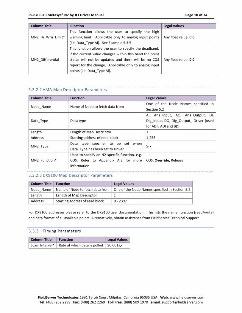
Column Title Function Legal Values
MN2_Hi_Wrn_Limit*
This function allows the user to specify the high
warning limit. Applicable only to analog input points
(i.e. Data_Type AI). See Example 5.3.5
Any float value, 0.0
MN2_Differential
This function allows the user to specify the deadband.
If the current value changes within this band the point
status will not be updated and there will be no COS
report for the change. Applicable only to analog input
points (i.e. Data_Type AI).
Any float value, 0.0
5.3.2.2 VMA Map Descriptor Parameters
Column Title Function Legal Values
Node_Name Name of Node to fetch data from One of the Node Names specified in
Section 5.2
Data_Type Data type
AI, Ana_Input, AO, Ana_Output, DI,
Dig_Input, DO, Dig_Output,, Driver (used
for ADF, ADI and BD)
Length Length of Map Descriptor 1
Address Starting address of read block 1-256
MN2_Type Data type specifier to be set when
Data_Type has been set to Driver 5-7
MN2_Function*
Used to specify an N2-specific function, e.g.
COS. Refer to Appendix A.3 for more
information.
COS, Override, Release
5.3.2.3 DX9100 Map Descriptor Parameters
Column Title Function Legal Values
Node_Name Name of Node to fetch data from One of the Node Names specified in Section 5.2
Length Length of Map Descriptor 1
Address Starting address of read block 0 - 2397
For DX9100 addresses please refer to the DX9100 user documentation. This lists the name, function (read/write)
and data format of all available points. Alternatively, obtain assistance from FieldServer Technical Support.
5.3.3 Timing Parameters
Column Title Function Legal Values
Scan_Interval* Rate at which data is polled ≥0.001s,-
FS-8700-19 Metasys® N2 by JCI Driver Manual Page 11 of 34
FieldServer Technologies 1991 Tarob Court Milpitas, California 95035 USA Web: www.fieldserver.com Tel: (408) 262 2299 Fax: (408) 262 2269 Toll Free: (888) 509 1970 email: [email protected]
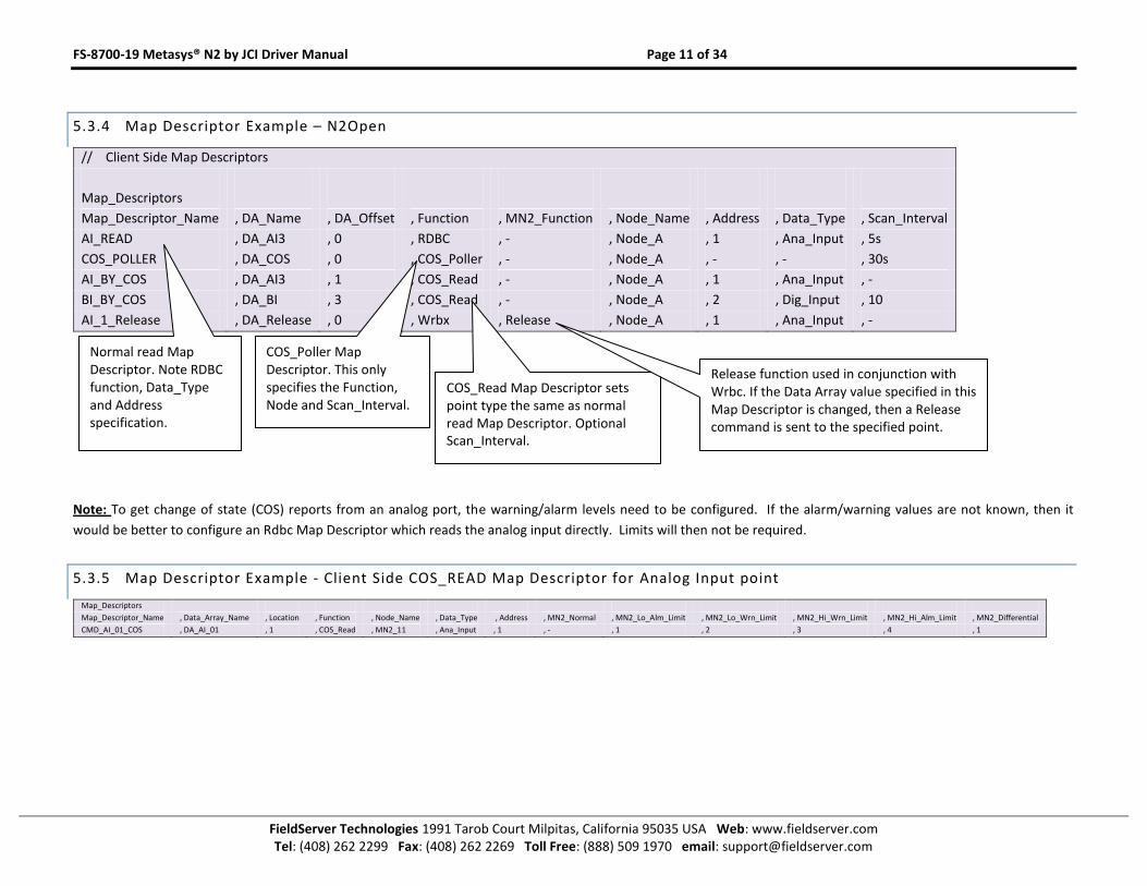
5.3.4 Map Descriptor Example – N2Open
// Client Side Map Descriptors
Map_Descriptors
Map_Descriptor_Name , DA_Name , DA_Offset , Function , MN2_Function , Node_Name , Address , Data_Type , Scan_Interval
AI_READ , DA_AI3 , 0 , RDBC , - , Node_A , 1 , Ana_Input , 5s
COS_POLLER , DA_COS , 0 , COS_Poller , - , Node_A , - , - , 30s
AI_BY_COS , DA_AI3 , 1 , COS_Read , - , Node_A , 1 , Ana_Input , -
BI_BY_COS , DA_BI , 3 , COS_Read , - , Node_A , 2 , Dig_Input , 10
AI_1_Release , DA_Release , 0 , Wrbx , Release , Node_A , 1 , Ana_Input , -
Note: To get change of state (COS) reports from an analog port, the warning/alarm levels need to be configured. If the alarm/warning values are not known, then it
would be better to configure an Rdbc Map Descriptor which reads the analog input directly. Limits will then not be required.
5.3.5 Map Descriptor Example - Client Side COS_READ Map Descriptor for Analog Input point
Map_Descriptors
Map_Descriptor_Name , Data_Array_Name , Location , Function , Node_Name , Data_Type , Address , MN2_Normal , MN2_Lo_Alm_Limit , MN2_Lo_Wrn_Limit , MN2_Hi_Wrn_Limit , MN2_Hi_Alm_Limit , MN2_Differential
CMD_AI_01_COS , DA_AI_01 , 1 , COS_Read , MN2_11 , Ana_Input , 1 , - , 1 , 2 , 3 , 4 , 1
Normal read Map Descriptor. Note RDBC function, Data_Type and Address specification.
COS_Read Map Descriptor sets point type the same as normal read Map Descriptor. Optional Scan_Interval.
Release function used in conjunction with Wrbc. If the Data Array value specified in this Map Descriptor is changed, then a Release command is sent to the specified point.
COS_Poller Map Descriptor. This only specifies the Function, Node and Scan_Interval.
FS-8700-19 Metasys® N2 by JCI Driver Manual Page 12 of 34
FieldServer Technologies 1991 Tarob Court Milpitas, California 95035 USA Web: www.fieldserver.com Tel: (408) 262 2299 Fax: (408) 262 2269 Toll Free: (888) 509 1970 email: [email protected]
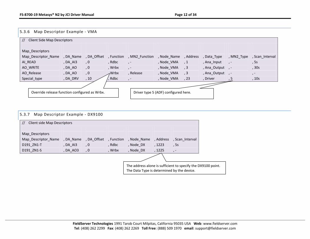
5.3.6 Map Descriptor Example - VMA
// Client Side Map Descriptors
Map_Descriptors
Map_Descriptor_Name , DA_Name , DA_Offset , Function , MN2_Function , Node_Name , Address , Data_Type , MN2_Type , Scan_Interval
AI_READ , DA_AI3 , 0 , Rdbc , - , Node_VMA , 1 , Ana_Input , - , 5s
AO_WRITE , DA_AO , 0 , Wrbx , - , Node_VMA , 3 , Ana_Output , - , 30s
AO_Release , DA_AO , 0 , Wrbx , Release , Node_VMA , 3 , Ana_Output , - , -
Special_type , DA_DRV , 10 , Rdbc , - , Node_VMA , 23 , Driver , 5 , 10s
5.3.7 Map Descriptor Example - DX9100
// Client side Map Descriptors
Map_Descriptors
Map_Descriptor_Name , DA_Name , DA_Offset , Function , Node_Name , Address , Scan_Interval
D191_ZN1-T , DA_AI3 , 0 , Rdbc , Node_DX , 1223 , 5s
D191_ZN1-S , DA_AO3 , 0 , Wrbx , Node_DX , 1225 , -
Override release function configured as Wrbx. Driver type 5 (ADF) configured here.
The address alone is sufficient to specify the DX9100 point. The Data Type is determined by the device.
FS-8700-19 Metasys® N2 by JCI Driver Manual Page 13 of 34
FieldServer Technologies 1991 Tarob Court Milpitas, California 95035 USA Web: www.fieldserver.com Tel: (408) 262 2299 Fax: (408) 262 2269 Toll Free: (888) 509 1970 email: [email protected]
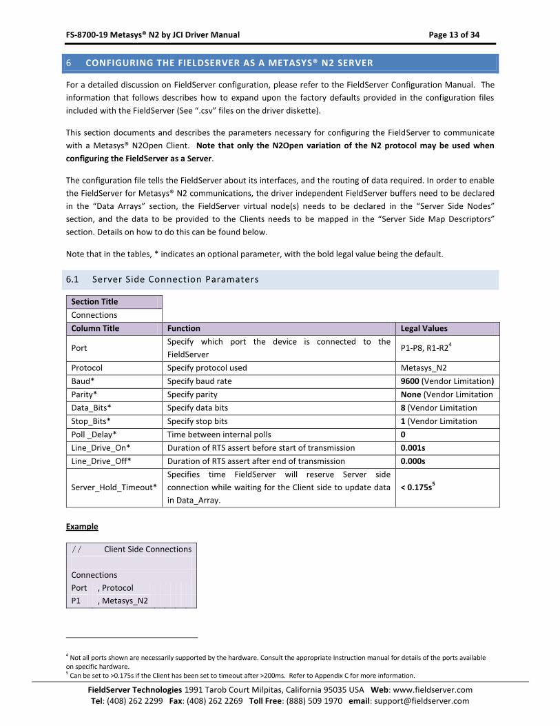
6 CONFIGURING THE FIELDSERVER AS A METASYS® N2 SERVER
For a detailed discussion on FieldServer configuration, please refer to the FieldServer Configuration Manual. The
information that follows describes how to expand upon the factory defaults provided in the configuration files
included with the FieldServer (See “.csv” files on the driver diskette).
This section documents and describes the parameters necessary for configuring the FieldServer to communicate
with a Metasys® N2Open Client. Note that only the N2Open variation of the N2 protocol may be used when
configuring the FieldServer as a Server.
The configuration file tells the FieldServer about its interfaces, and the routing of data required. In order to enable
the FieldServer for Metasys® N2 communications, the driver independent FieldServer buffers need to be declared
in the “Data Arrays” section, the FieldServer virtual node(s) needs to be declared in the “Server Side Nodes”
section, and the data to be provided to the Clients needs to be mapped in the “Server Side Map Descriptors”
section. Details on how to do this can be found below.
Note that in the tables, * indicates an optional parameter, with the bold legal value being the default.
6.1 Server Side Connection Paramaters
Section Title
Connections
Column Title Function Legal Values
Port Specify which port the device is connected to the
FieldServer P1-P8, R1-R2
4
Protocol Specify protocol used Metasys_N2
Baud* Specify baud rate 9600 (Vendor Limitation)
Parity* Specify parity None (Vendor Limitation
Data_Bits* Specify data bits 8 (Vendor Limitation
Stop_Bits* Specify stop bits 1 (Vendor Limitation
Poll _Delay* Time between internal polls 0
Line_Drive_On* Duration of RTS assert before start of transmission 0.001s
Line_Drive_Off* Duration of RTS assert after end of transmission 0.000s
Server_Hold_Timeout*
Specifies time FieldServer will reserve Server side
connection while waiting for the Client side to update data
in Data_Array.
< 0.175s5
Example
// Client Side Connections
Connections
Port , Protocol
P1 , Metasys_N2
4 Not all ports shown are necessarily supported by the hardware. Consult the appropriate Instruction manual for details of the ports available on specific hardware. 5 Can be set to >0.175s if the Client has been set to timeout after >200ms. Refer to Appendix C for more information.
FS-8700-19 Metasys® N2 by JCI Driver Manual Page 14 of 34
FieldServer Technologies 1991 Tarob Court Milpitas, California 95035 USA Web: www.fieldserver.com Tel: (408) 262 2299 Fax: (408) 262 2269 Toll Free: (888) 509 1970 email: [email protected]
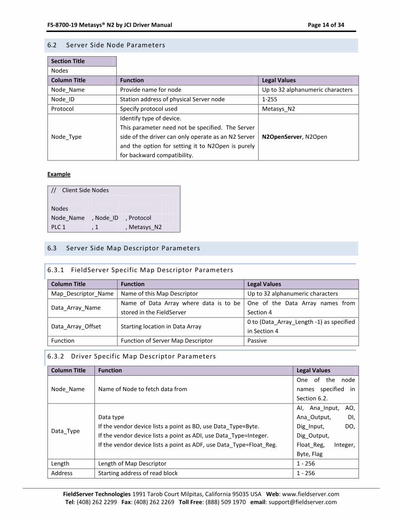
6.2 Server Side Node Parameters
Section Title
Nodes
Column Title Function Legal Values
Node_Name Provide name for node Up to 32 alphanumeric characters
Node_ID Station address of physical Server node 1-255
Protocol Specify protocol used Metasys_N2
Node_Type
Identify type of device.
This parameter need not be specified. The Server
side of the driver can only operate as an N2 Server
and the option for setting it to N2Open is purely
for backward compatibility.
N2OpenServer, N2Open
Example
// Client Side Nodes
Nodes
Node_Name , Node_ID , Protocol
PLC 1 , 1 , Metasys_N2
6.3 Server Side Map Descriptor Parameters
6.3.1 FieldServer Specific Map Descriptor Parameters
Column Title Function Legal Values
Map_Descriptor_Name Name of this Map Descriptor Up to 32 alphanumeric characters
Data_Array_Name Name of Data Array where data is to be
stored in the FieldServer
One of the Data Array names from
Section 4
Data_Array_Offset Starting location in Data Array 0 to (Data_Array_Length -1) as specified
in Section 4
Function Function of Server Map Descriptor Passive
6.3.2 Driver Specific Map Descriptor Parameters
Column Title Function Legal Values
Node_Name Name of Node to fetch data from
One of the node
names specified in
Section 6.2.
Data_Type
Data type
If the vendor device lists a point as BD, use Data_Type=Byte.
If the vendor device lists a point as ADI, use Data_Type=Integer.
If the vendor device lists a point as ADF, use Data_Type=Float_Reg.
AI, Ana_Input, AO,
Ana_Output, DI,
Dig_Input, DO,
Dig_Output,
Float_Reg, Integer,
Byte, Flag
Length Length of Map Descriptor 1 - 256
Address Starting address of read block 1 - 256
FS-8700-19 Metasys® N2 by JCI Driver Manual Page 15 of 34
FieldServer Technologies 1991 Tarob Court Milpitas, California 95035 USA Web: www.fieldserver.com Tel: (408) 262 2299 Fax: (408) 262 2269 Toll Free: (888) 509 1970 email: [email protected]
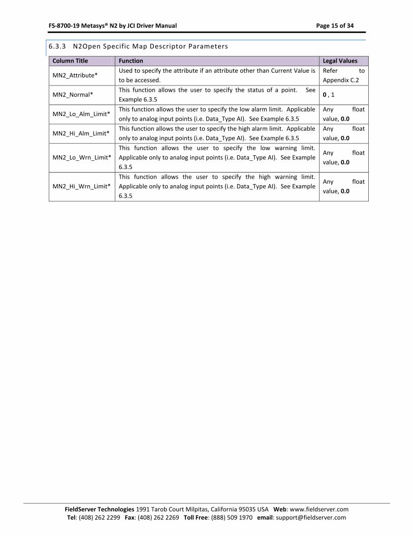
6.3.3 N2Open Specific Map Descriptor Parameters
Column Title Function Legal Values
MN2_Attribute* Used to specify the attribute if an attribute other than Current Value is
to be accessed.
Refer to
Appendix C.2
MN2_Normal* This function allows the user to specify the status of a point. See
Example 6.3.5 0 , 1
MN2_Lo_Alm_Limit* This function allows the user to specify the low alarm limit. Applicable
only to analog input points (i.e. Data_Type AI). See Example 6.3.5
Any float
value, 0.0
MN2_Hi_Alm_Limit* This function allows the user to specify the high alarm limit. Applicable
only to analog input points (i.e. Data_Type AI). See Example 6.3.5
Any float
value, 0.0
MN2_Lo_Wrn_Limit*
This function allows the user to specify the low warning limit.
Applicable only to analog input points (i.e. Data_Type AI). See Example
6.3.5
Any float
value, 0.0
MN2_Hi_Wrn_Limit*
This function allows the user to specify the high warning limit.
Applicable only to analog input points (i.e. Data_Type AI). See Example
6.3.5
Any float
value, 0.0
FS-8700-19 Metasys® N2 by JCI Driver Manual Page 16 of 34
FieldServer Technologies 1991 Tarob Court Milpitas, California 95035 USA Web: www.fieldserver.com Tel: (408) 262 2299 Fax: (408) 262 2269 Toll Free: (888) 509 1970 email: [email protected]
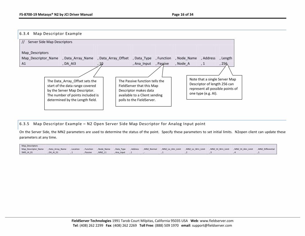
6.3.4 Map Descriptor Example
// Server Side Map Descriptors
Map_Descriptors
Map_Descriptor_Name , Data_Array_Name , Data_Array_Offset , Data_Type , Function , Node_Name , Address , Length
A1 , DA_AI3 , 10 , Ana_Input , Passive , Node_A , 1 , 256
6.3.5 Map Descriptor Example – N2 Open Server Side Map Descriptor for Analog Input point
On the Server Side, the MN2 parameters are used to determine the status of the point. Specify these parameters to set initial limits. N2open client can update these
parameters at any time.
Map_Descriptors
Map_Descriptor_Name , Data_Array_Name , Location , Function , Node_Name , Data_Type , Address , MN2_Normal , MN2_Lo_Alm_Limit , MN2_Lo_Wrn_Limit , MN2_Hi_Wrn_Limit , MN2_Hi_Alm_Limit , MN2_Differential
SMD_AI_01 , DA_AI_01 , 1 , Passive , MN2_11 , Ana_Input , 1 , - , 1 , 2 , 3 , 4 , 1
The Passive function tells the FieldServer that this Map Descriptor makes data available to a Client sending polls to the FieldServer.
Note that a single Server Map Descriptor of length 256 can represent all possible points of one type (e.g. AI).
The Data_Array_Offset sets the start of the data range covered by the Server Map Descriptor. The number of points included is determined by the Length field.
FS-8700-19 Metasys® N2 by JCI Driver Manual Page 17 of 34
FieldServer Technologies 1991 Tarob Court Milpitas, California 95035 USA Web: www.fieldserver.com Tel: (408) 262 2299 Fax: (408) 262 2269 Toll Free: (888) 509 1970 email: [email protected]
Appendix A. Useful Features
Appendix A.1. Writing to DX9100 Binary Outputs
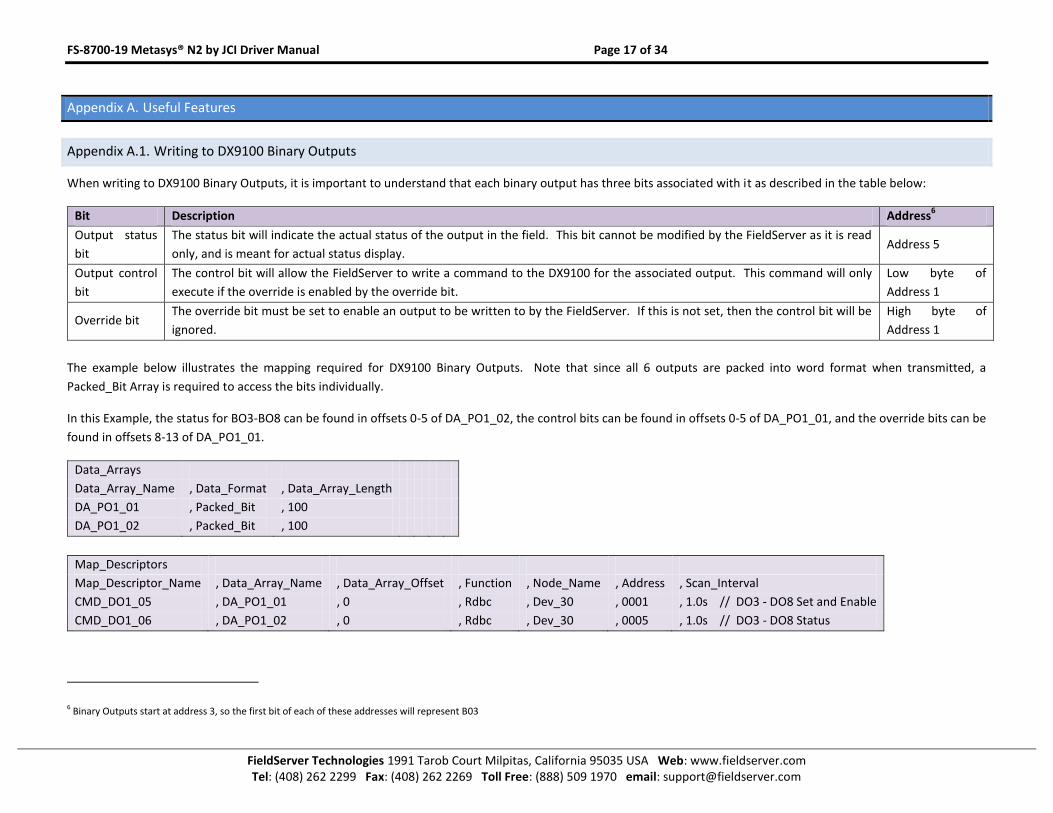
When writing to DX9100 Binary Outputs, it is important to understand that each binary output has three bits associated with it as described in the table below:
Bit Description Address6
Output status
bit
The status bit will indicate the actual status of the output in the field. This bit cannot be modified by the FieldServer as it is read
only, and is meant for actual status display. Address 5
Output control
bit
The control bit will allow the FieldServer to write a command to the DX9100 for the associated output. This command will only
execute if the override is enabled by the override bit.
Low byte of
Address 1
Override bit The override bit must be set to enable an output to be written to by the FieldServer. If this is not set, then the control bit will be
ignored.
High byte of
Address 1
The example below illustrates the mapping required for DX9100 Binary Outputs. Note that since all 6 outputs are packed into word format when transmitted, a
Packed_Bit Array is required to access the bits individually.
In this Example, the status for BO3-BO8 can be found in offsets 0-5 of DA_PO1_02, the control bits can be found in offsets 0-5 of DA_PO1_01, and the override bits can be
found in offsets 8-13 of DA_PO1_01.
Data_Arrays
Data_Array_Name , Data_Format , Data_Array_Length
DA_PO1_01 , Packed_Bit , 100
DA_PO1_02 , Packed_Bit , 100
Map_Descriptors
Map_Descriptor_Name , Data_Array_Name , Data_Array_Offset , Function , Node_Name , Address , Scan_Interval
CMD_DO1_05 , DA_PO1_01 , 0 , Rdbc , Dev_30 , 0001 , 1.0s // DO3 - DO8 Set and Enable
CMD_DO1_06 , DA_PO1_02 , 0 , Rdbc , Dev_30 , 0005 , 1.0s // DO3 - DO8 Status
6 Binary Outputs start at address 3, so the first bit of each of these addresses will represent B03
FS-8700-19 Metasys® N2 by JCI Driver Manual Page 18 of 34
FieldServer Technologies 1991 Tarob Court Milpitas, California 95035 USA Web: www.fieldserver.com Tel: (408) 262 2299 Fax: (408) 262 2269 Toll Free: (888) 509 1970 email: [email protected]
Appendix A.2. Managing Analog Inputs and Outputs for DX9100.
Relative offset for viewing an AI is 7
Relative offset for viewing and forcing an AO is 6
Appendix A.3. Using Override and Release – N2Open
It is not normally necessary to use the Override command explicitly as the FieldServer automatically uses this
command when the Current Value attribute of a point is written. For any other attribute it uses the Write
command. It will sometimes be necessary to send a Release command to an overridden point, however. To do
this, a Map Descriptor must be configured with Function set to Wrbx and MN2_Function set to Release. Then,
when any value is stored to the Map Descriptor data location, the Release command will be sent to the N2Open
point specified by the Map Descriptor.
FS-8700-19 Metasys® N2 by JCI Driver Manual Page 19 of 34
FieldServer Technologies 1991 Tarob Court Milpitas, California 95035 USA Web: www.fieldserver.com Tel: (408) 262 2299 Fax: (408) 262 2269 Toll Free: (888) 509 1970 email: [email protected]
Appendix A.4. Using Change of State (COS) – N2Open
If a large number of points are to be monitored, optimal efficiency is achieved by using the COS mechanism instead of reading each individual point directly. A N2Open
device responds to a COS poll with a change record if a change has taken place. On startup the device will report the state of all its points when it receives a COS poll.
Two kinds of Map Descriptors are required for everyNode that is to be monitored using COS:
A COS polling Map Descriptor with Function set to COS_Poller.
A COS_Read (i.e. Function set to COS_Read) Map Descriptor for every point on that node that is to be monitored. Any COS records received will be stored to the
matching Map Descriptor data location.
Note that the COS_Read Map Descriptor has an optional scan_interval. If a value is set the Map Descriptor will poll at that rate in addition to receiving COS data. This can
be used if the values are to be refreshed continually even if they don’t change. If the scan_interval is not configured (through omitting the column, or by setting the value
to ‘-‘) the COS_Read Map Descriptor will not cause active polls once the value has been initialized. See Section 5.3.4 for example.
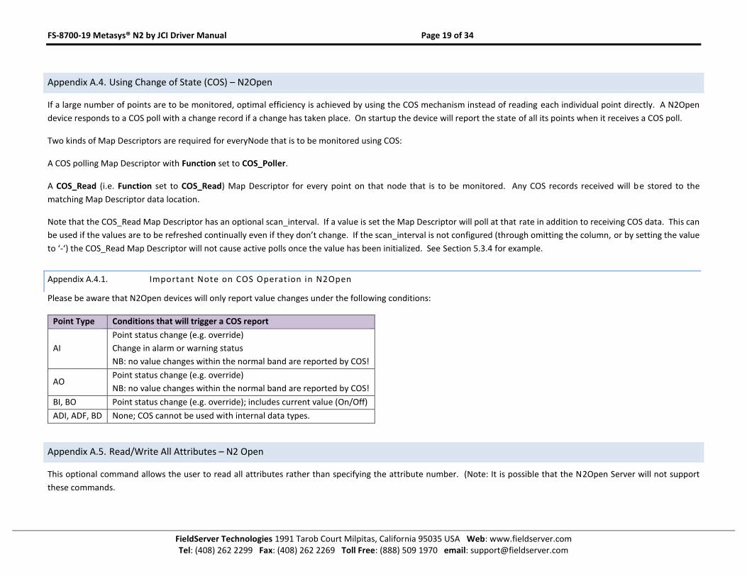
Appendix A.4.1. Important Note on COS Operation in N2Open
Please be aware that N2Open devices will only report value changes under the following conditions:
Point Type Conditions that will trigger a COS report
AI
Point status change (e.g. override)
Change in alarm or warning status
NB: no value changes within the normal band are reported by COS!
AO Point status change (e.g. override)
NB: no value changes within the normal band are reported by COS!
BI, BO Point status change (e.g. override); includes current value (On/Off)
ADI, ADF, BD None; COS cannot be used with internal data types.
Appendix A.5. Read/Write All Attributes – N2 Open
This optional command allows the user to read all attributes rather than specifying the attribute number. (Note: It is possible that the N2Open Server will not support
these commands.
FS-8700-19 Metasys® N2 by JCI Driver Manual Page 20 of 34
FieldServer Technologies 1991 Tarob Court Milpitas, California 95035 USA Web: www.fieldserver.com Tel: (408) 262 2299 Fax: (408) 262 2269 Toll Free: (888) 509 1970 email: [email protected]
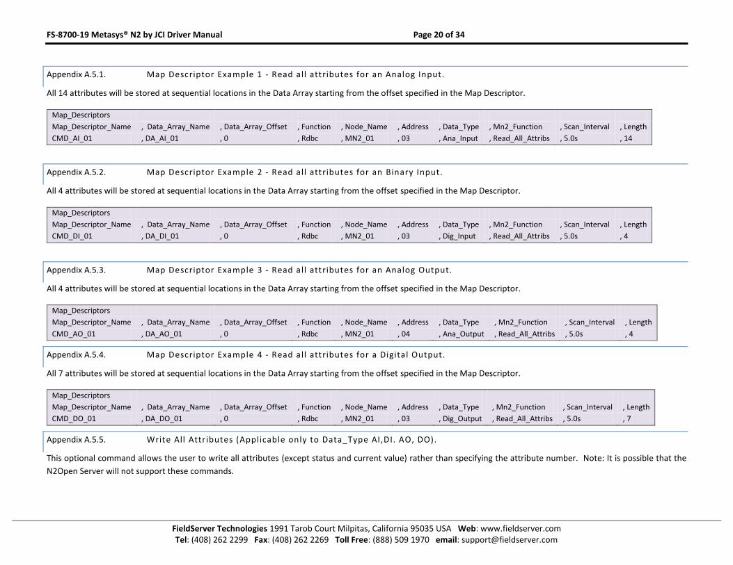
Appendix A.5.1. Map Descriptor Example 1 - Read all attributes for an Analog Input.
All 14 attributes will be stored at sequential locations in the Data Array starting from the offset specified in the Map Descriptor.
Map_Descriptors
Map_Descriptor_Name , Data_Array_Name , Data_Array_Offset , Function , Node_Name , Address , Data_Type , Mn2_Function , Scan_Interval , Length
CMD_AI_01 , DA_AI_01 , 0 , Rdbc , MN2_01 , 03 , Ana_Input , Read_All_Attribs , 5.0s , 14
Appendix A.5.2. Map Descriptor Example 2 - Read all attributes for an Binary Input.
All 4 attributes will be stored at sequential locations in the Data Array starting from the offset specified in the Map Descriptor.
Map_Descriptors
Map_Descriptor_Name , Data_Array_Name , Data_Array_Offset , Function , Node_Name , Address , Data_Type , Mn2_Function , Scan_Interval , Length
CMD_DI_01 , DA_DI_01 , 0 , Rdbc , MN2_01 , 03 , Dig_Input , Read_All_Attribs , 5.0s , 4
Appendix A.5.3. Map Descriptor Example 3 - Read all attributes for an Analog Output.
All 4 attributes will be stored at sequential locations in the Data Array starting from the offset specified in the Map Descriptor.
Map_Descriptors
Map_Descriptor_Name , Data_Array_Name , Data_Array_Offset , Function , Node_Name , Address , Data_Type , Mn2_Function , Scan_Interval , Length
CMD_AO_01 , DA_AO_01 , 0 , Rdbc , MN2_01 , 04 , Ana_Output , Read_All_Attribs , 5.0s , 4
Appendix A.5.4. Map Descriptor Example 4 - Read all attributes for a Digital Output.
All 7 attributes will be stored at sequential locations in the Data Array starting from the offset specified in the Map Descriptor.
Map_Descriptors
Map_Descriptor_Name , Data_Array_Name , Data_Array_Offset , Function , Node_Name , Address , Data_Type , Mn2_Function , Scan_Interval , Length
CMD_DO_01 , DA_DO_01 , 0 , Rdbc , MN2_01 , 03 , Dig_Output , Read_All_Attribs , 5.0s , 7
Appendix A.5.5. Write All Attributes (Applicable only to Data_Type AI,DI. AO, DO).
This optional command allows the user to write all attributes (except status and current value) rather than specifying the attribute number. Note: It is possible that the
N2Open Server will not support these commands.
FS-8700-19 Metasys® N2 by JCI Driver Manual Page 21 of 34
FieldServer Technologies 1991 Tarob Court Milpitas, California 95035 USA Web: www.fieldserver.com Tel: (408) 262 2299 Fax: (408) 262 2269 Toll Free: (888) 509 1970 email: [email protected]
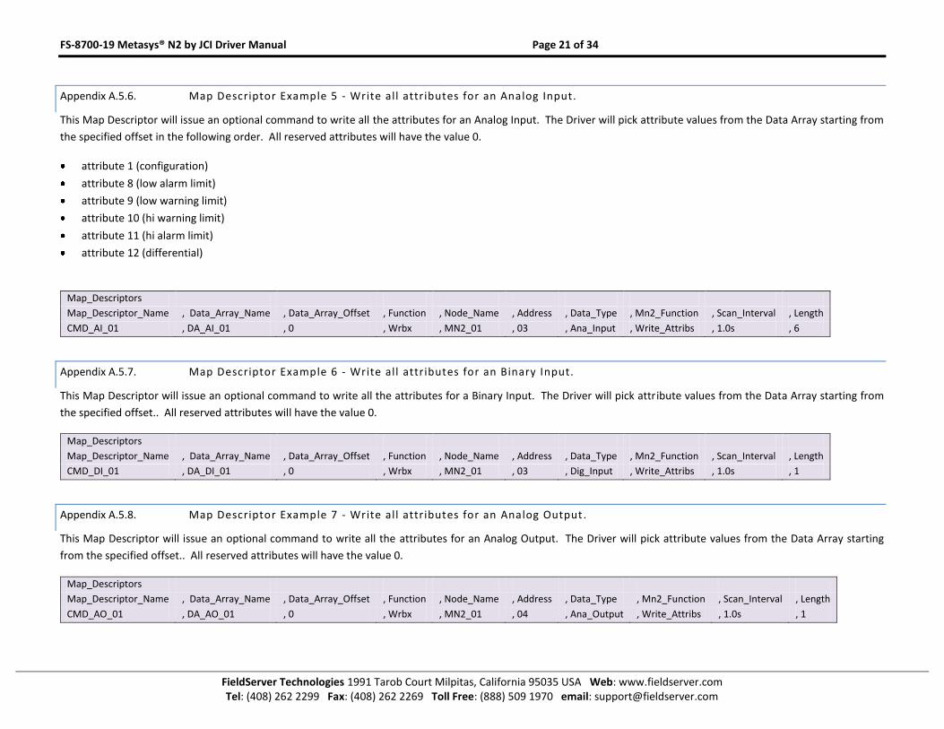
Appendix A.5.6. Map Descriptor Example 5 - Write all attributes for an Analog Input.
This Map Descriptor will issue an optional command to write all the attributes for an Analog Input. The Driver will pick attribute values from the Data Array starting from
the specified offset in the following order. All reserved attributes will have the value 0.
attribute 1 (configuration)
attribute 8 (low alarm limit)
attribute 9 (low warning limit)
attribute 10 (hi warning limit)
attribute 11 (hi alarm limit)
attribute 12 (differential)
Map_Descriptors
Map_Descriptor_Name , Data_Array_Name , Data_Array_Offset , Function , Node_Name , Address , Data_Type , Mn2_Function , Scan_Interval , Length
CMD_AI_01 , DA_AI_01 , 0 , Wrbx , MN2_01 , 03 , Ana_Input , Write_Attribs , 1.0s , 6
Appendix A.5.7. Map Descriptor Example 6 - Write all attributes for an Binary Input.
This Map Descriptor will issue an optional command to write all the attributes for a Binary Input. The Driver will pick attribute values from the Data Array starting from
the specified offset.. All reserved attributes will have the value 0.
Map_Descriptors
Map_Descriptor_Name , Data_Array_Name , Data_Array_Offset , Function , Node_Name , Address , Data_Type , Mn2_Function , Scan_Interval , Length
CMD_DI_01 , DA_DI_01 , 0 , Wrbx , MN2_01 , 03 , Dig_Input , Write_Attribs , 1.0s , 1
Appendix A.5.8. Map Descriptor Example 7 - Write all attributes for an Analog Output .
This Map Descriptor will issue an optional command to write all the attributes for an Analog Output. The Driver will pick attribute values from the Data Array starting
from the specified offset.. All reserved attributes will have the value 0.
Map_Descriptors
Map_Descriptor_Name , Data_Array_Name , Data_Array_Offset , Function , Node_Name , Address , Data_Type , Mn2_Function , Scan_Interval , Length
CMD_AO_01 , DA_AO_01 , 0 , Wrbx , MN2_01 , 04 , Ana_Output , Write_Attribs , 1.0s , 1
FS-8700-19 Metasys® N2 by JCI Driver Manual Page 22 of 34
FieldServer Technologies 1991 Tarob Court Milpitas, California 95035 USA Web: www.fieldserver.com Tel: (408) 262 2299 Fax: (408) 262 2269 Toll Free: (888) 509 1970 email: [email protected]
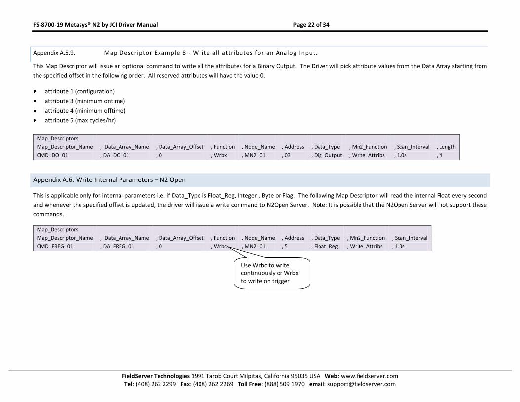
Appendix A.5.9. Map Descriptor Example 8 - Write all attributes for an Analog Input.
This Map Descriptor will issue an optional command to write all the attributes for a Binary Output. The Driver will pick attribute values from the Data Array starting from
the specified offset in the following order. All reserved attributes will have the value 0.
attribute 1 (configuration)
attribute 3 (minimum ontime)
attribute 4 (minimum offtime)
attribute 5 (max cycles/hr)
Map_Descriptors
Map_Descriptor_Name , Data_Array_Name , Data_Array_Offset , Function , Node_Name , Address , Data_Type , Mn2_Function , Scan_Interval , Length
CMD_DO_01 , DA_DO_01 , 0 , Wrbx , MN2_01 , 03 , Dig_Output , Write_Attribs , 1.0s , 4
Appendix A.6. Write Internal Parameters – N2 Open
This is applicable only for internal parameters i.e. if Data_Type is Float_Reg, Integer , Byte or Flag. The following Map Descriptor will read the internal Float every second
and whenever the specified offset is updated, the driver will issue a write command to N2Open Server. Note: It is possible that the N2Open Server will not support these
commands.
Map_Descriptors
Map_Descriptor_Name , Data_Array_Name , Data_Array_Offset , Function , Node_Name , Address , Data_Type , Mn2_Function , Scan_Interval
CMD_FREG_01 , DA_FREG_01 , 0 , Wrbc , MN2_01 , 5 , Float_Reg , Write_Attribs , 1.0s
Use Wrbc to write continuously or Wrbx to write on trigger
FS-8700-19 Metasys® N2 by JCI Driver Manual Page 23 of 34
FieldServer Technologies 1991 Tarob Court Milpitas, California 95035 USA Web: www.fieldserver.com Tel: (408) 262 2299 Fax: (408) 262 2269 Toll Free: (888) 509 1970 email: [email protected]
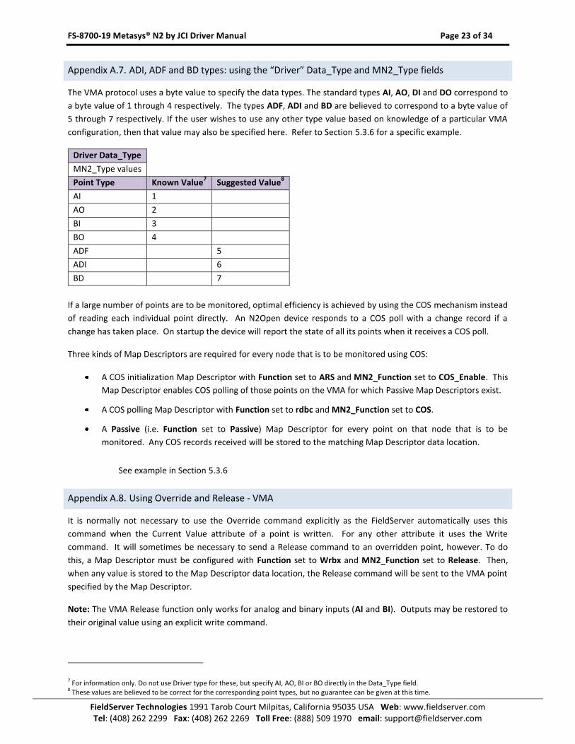
Appendix A.7. ADI, ADF and BD types: using the “Driver” Data_Type and MN2_Type fields
The VMA protocol uses a byte value to specify the data types. The standard types AI, AO, DI and DO correspond to
a byte value of 1 through 4 respectively. The types ADF, ADI and BD are believed to correspond to a byte value of
5 through 7 respectively. If the user wishes to use any other type value based on knowledge of a particular VMA
configuration, then that value may also be specified here. Refer to Section 5.3.6 for a specific example.
Driver Data_Type
MN2_Type values
Point Type Known Value7 Suggested Value
8
AI 1
AO 2
BI 3
BO 4
ADF 5
ADI 6
BD 7
If a large number of points are to be monitored, optimal efficiency is achieved by using the COS mechanism instead
of reading each individual point directly. An N2Open device responds to a COS poll with a change record if a
change has taken place. On startup the device will report the state of all its points when it receives a COS poll.
Three kinds of Map Descriptors are required for every node that is to be monitored using COS:
A COS initialization Map Descriptor with Function set to ARS and MN2_Function set to COS_Enable. This
Map Descriptor enables COS polling of those points on the VMA for which Passive Map Descriptors exist.
A COS polling Map Descriptor with Function set to rdbc and MN2_Function set to COS.
A Passive (i.e. Function set to Passive) Map Descriptor for every point on that node that is to be
monitored. Any COS records received will be stored to the matching Map Descriptor data location.
See example in Section 5.3.6
Appendix A.8. Using Override and Release - VMA
It is normally not necessary to use the Override command explicitly as the FieldServer automatically uses this
command when the Current Value attribute of a point is written. For any other attribute it uses the Write
command. It will sometimes be necessary to send a Release command to an overridden point, however. To do
this, a Map Descriptor must be configured with Function set to Wrbx and MN2_Function set to Release. Then,
when any value is stored to the Map Descriptor data location, the Release command will be sent to the VMA point
specified by the Map Descriptor.
Note: The VMA Release function only works for analog and binary inputs (AI and BI). Outputs may be restored to
their original value using an explicit write command.
7 For information only. Do not use Driver type for these, but specify AI, AO, BI or BO directly in the Data_Type field. 8 These values are believed to be correct for the corresponding point types, but no guarantee can be given at this time.
FS-8700-19 Metasys® N2 by JCI Driver Manual Page 24 of 34
FieldServer Technologies 1991 Tarob Court Milpitas, California 95035 USA Web: www.fieldserver.com Tel: (408) 262 2299 Fax: (408) 262 2269 Toll Free: (888) 509 1970 email: [email protected]
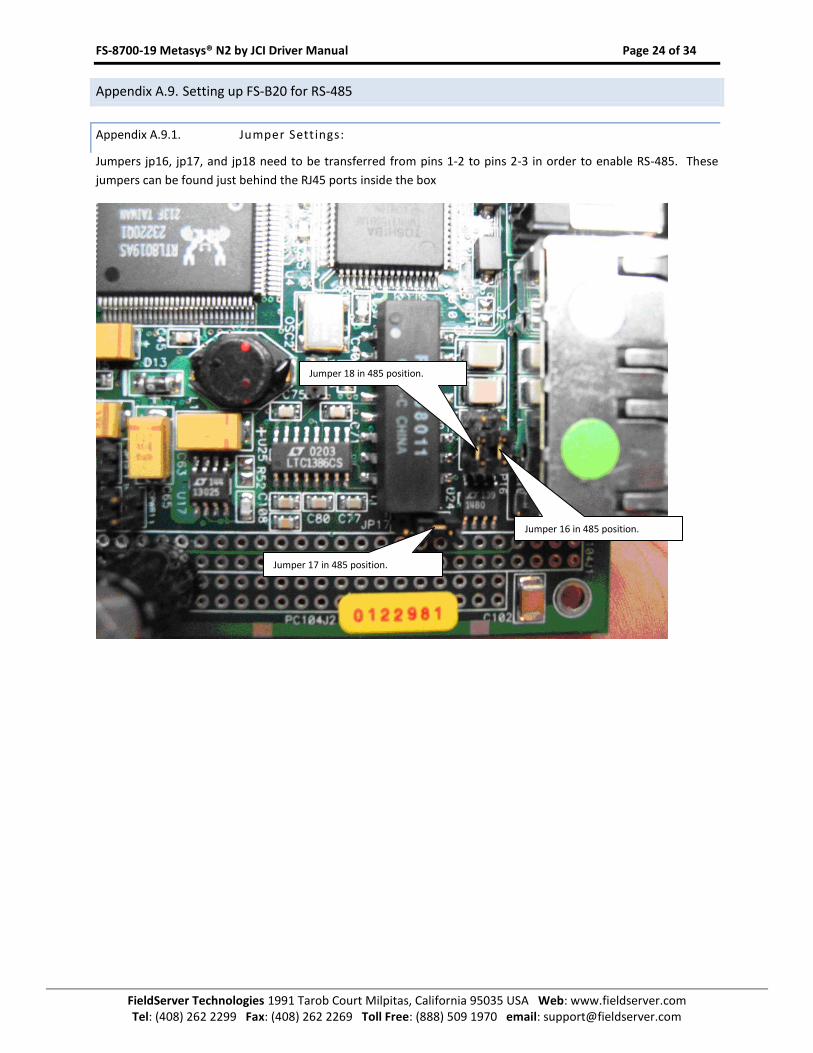
Appendix A.9. Setting up FS-B20 for RS-485
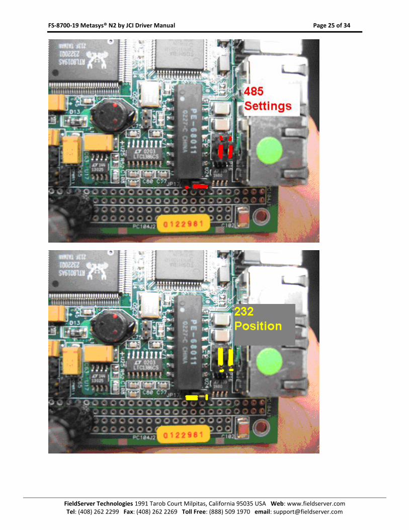
Appendix A.9.1. Jumper Settings:
Jumpers jp16, jp17, and jp18 need to be transferred from pins 1-2 to pins 2-3 in order to enable RS-485. These
jumpers can be found just behind the RJ45 ports inside the box
Jumper 17 in 485 position.
Jumper 16 in 485 position.
Jumper 18 in 485 position.
FS-8700-19 Metasys® N2 by JCI Driver Manual Page 25 of 34
FieldServer Technologies 1991 Tarob Court Milpitas, California 95035 USA Web: www.fieldserver.com Tel: (408) 262 2299 Fax: (408) 262 2269 Toll Free: (888) 509 1970 email: [email protected]
FS-8700-19 Metasys® N2 by JCI Driver Manual Page 26 of 34
FieldServer Technologies 1991 Tarob Court Milpitas, California 95035 USA Web: www.fieldserver.com Tel: (408) 262 2299 Fax: (408) 262 2269 Toll Free: (888) 509 1970 email: [email protected]
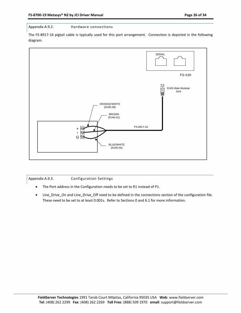
Appendix A.9.2. Hardware connections
The FS-8917-16 pigtail cable is typically used for this port arrangement. Connection is depicted in the following
diagram.
FS-8917-16
FS-X20
SERIAL
+-G
ORANGE/WHITE
(RJ45-08)
BROWN
(RJ45-01)
BLUE/WHITE
(RJ45-04)
RJ45 Male Modular
Jack
Appendix A.9.3. Configuration Settings
The Port address in the Configuration needs to be set to R1 instead of P1.
Line_Drive_On and Line_Drive_Off need to be defined in the connections section of the configuration file.
These need to be set to at least 0.001s. Refer to Sections 0 and 6.1 for more information.
FS-8700-19 Metasys® N2 by JCI Driver Manual Page 27 of 34
FieldServer Technologies 1991 Tarob Court Milpitas, California 95035 USA Web: www.fieldserver.com Tel: (408) 262 2299 Fax: (408) 262 2269 Toll Free: (888) 509 1970 email: [email protected]
Appendix B. Troubleshooting tips
Appendix B.1. Offline Behavior
When the Client node on the FieldServer goes offline, the corresponding data objects on the FieldServer are also
marked offline. If a client polls a virtual FieldServer node for this particular data, therefore, an offline response will
be returned by the FieldServer. A request from a master device for a FieldServer to identify itself would be met by
a valid response, however. This could lead to confusion and status toggling. This can be addressed using
Responsible Map Descriptors and by configuring the virtual FieldServer using the Offline_Method option. Please
refer to the Configuration Manual for further information.
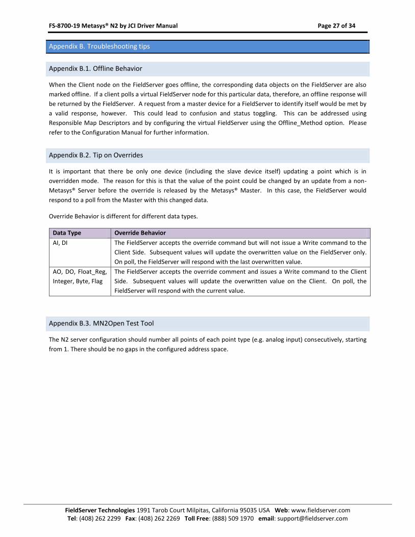
Appendix B.2. Tip on Overrides
It is important that there be only one device (including the slave device itself) updating a point which is in
overridden mode. The reason for this is that the value of the point could be changed by an update from a non-
Metasys® Server before the override is released by the Metasys® Master. In this case, the FieldServer would
respond to a poll from the Master with this changed data.
Override Behavior is different for different data types.
Data Type Override Behavior
AI, DI The FieldServer accepts the override command but will not issue a Write command to the
Client Side. Subsequent values will update the overwritten value on the FieldServer only.
On poll, the FieldServer will respond with the last overwritten value.
AO, DO, Float_Reg,
Integer, Byte, Flag
The FieldServer accepts the override comment and issues a Write command to the Client
Side. Subsequent values will update the overwritten value on the Client. On poll, the
FieldServer will respond with the current value.
Appendix B.3. MN2Open Test Tool
The N2 server configuration should number all points of each point type (e.g. analog input) consecutively, starting
from 1. There should be no gaps in the configured address space.
FS-8700-19 Metasys® N2 by JCI Driver Manual Page 28 of 34
FieldServer Technologies 1991 Tarob Court Milpitas, California 95035 USA Web: www.fieldserver.com Tel: (408) 262 2299 Fax: (408) 262 2269 Toll Free: (888) 509 1970 email: [email protected]
Appendix C. Reference
Appendix C.1. Error Messages
Error Message Description and Action
MN2:#01 WARN.
Server_Hold_Timeout is
%0.3fs
For N2Open Slave
typical value is %0.3fs
Typically N2open Clients are configured to timeout after 200ms. If a FieldServer is configured
as a Server the Server_Hold_Timeout time should be set to 0.175s or less otherwise the
response will be suppressed. This message is printed if the Server_Hold_Timeout is set for
>0.175s.
If the Client’s timeout is >200ms this message may be ignored.
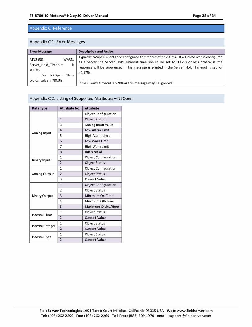
Appendix C.2. Listing of Supported Attributes – N2Open
Data Type Attribute No. Attribute
Analog Input
1 Object Configuration
2 Object Status
3 Analog Input Value
4 Low Alarm Limit
5 High Alarm Limit
6 Low Warn Limit
7 High Warn Limit
8 Differential
Binary Input 1 Object Configuration
2 Object Status
Analog Output
1 Object Configuration
2 Object Status
3 Current Value
Binary Output
1 Object Configuration
2 Object Status
3 Minimum On-Time
4 Minimum Off-Time
5 Maximum Cycles/Hour
Internal Float 1 Object Status
2 Current Value
Internal Integer 1 Object Status
2 Current Value
Internal Byte 1 Object Status
2 Current Value
FS-8700-19 Metasys® N2 by JCI Driver Manual Page 29 of 34
FieldServer Technologies 1991 Tarob Court Milpitas, California 95035 USA Web: www.fieldserver.com Tel: (408) 262 2299 Fax: (408) 262 2269 Toll Free: (888) 509 1970 email: [email protected]
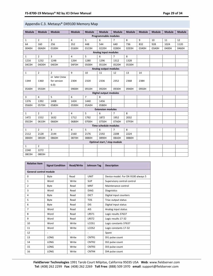
Appendix C.3. Metasys® DX9100 Memory Map
Module Module Module Module Module Module Module Module Module Module Module Module
Programmable modules
1 2 3 4 5 6 7 8 9 10 11 12
64 160 256 352 448 544 640 736 832 928 1024 1120
0040H 00A0H 0100H 0160H 01C0H 0220H 0280H 02E0H 0340H 03A0H 0400H 0460H
Analog input modules
1 2 3 4 5 6 7 8
1216 1232 1248 1264 1280 1296 1312 1328
04C0H 04D0H 04E0H 04F0H 0500H 0510H 0520H 0530H
Analog output modules
1 2 2 9 10 11 12 13 14
1344 1360
or later (new
for version
6.0):
2304 2320 2336 2352 2368 2384
0540H 0550H 0900H 0910H 0920H 0930H 0940H 0950H
Digital output modules
3 4 5 6 7 8
1376 1392 1408 1424 1440 1456
0560H 0570H 0580H 0590H 05A0H 05B0H
Extension modules
1 2 3 4 5 6 7 8
1472 1552 1632 1712 1792 1872 1952 2032
05C0H 0610H 0660H 06B0H 0700H 0750H 07A0H 07F0H
Time schedule modules
1 2 3 4 5 6 7 8
2112 2128 2144 2160 2176 2192 2208 2224
0840H 0850H 0860H 0870H 0880H 0890H 08A0H 08B0H
Optimal start / stop module
1 2
2240 2272
08C0H 08E0H
Relative Item
Signal Condition Read/Write Johnson Tag Description
General control module
0 Byte Read UNIT Device model. For DX-9100 always 5
1 Word Write SUP Supervisory central control
2 Byte Read MNT Maintenance control
3 Word Read DIAG Diagnistics
4 Byte Read DICT Digital input counters
5 Byte Read TOS Triac output status
6 Byte Read DIS Digital input status
7 Word Read AIS Analog input status
8 Word Read LRST1 Logic results 37637
9 Word Read LRST2 Logic results 17-32
10 Word Write LCOS1 Logic constants 37637
11 Word Write LCOS2 Logic constants 17-32
12 - - - Spare
13 LONG Write CNTR1 DI1 pulse count
14 LONG Write CNTR2 DI2 pulse count
15 LONG Write CNTR3 DI3 pulse count
16 LONG Write CNTR4 DI4 pulse count
FS-8700-19 Metasys® N2 by JCI Driver Manual Page 30 of 34
FieldServer Technologies 1991 Tarob Court Milpitas, California 95035 USA Web: www.fieldserver.com Tel: (408) 262 2299 Fax: (408) 262 2269 Toll Free: (888) 509 1970 email: [email protected]
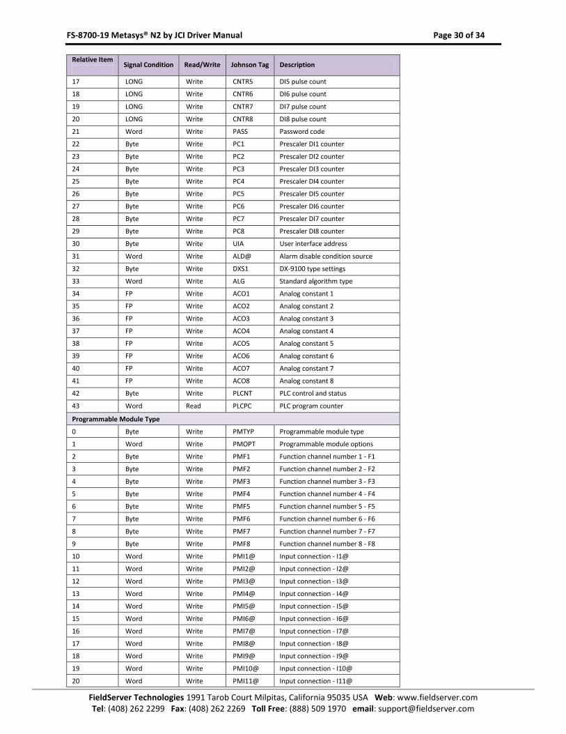
Relative Item
Signal Condition Read/Write Johnson Tag Description
17 LONG Write CNTR5 DI5 pulse count
18 LONG Write CNTR6 DI6 pulse count
19 LONG Write CNTR7 DI7 pulse count
20 LONG Write CNTR8 DI8 pulse count
21 Word Write PASS Password code
22 Byte Write PC1 Prescaler DI1 counter
23 Byte Write PC2 Prescaler DI2 counter
24 Byte Write PC3 Prescaler DI3 counter
25 Byte Write PC4 Prescaler DI4 counter
26 Byte Write PC5 Prescaler DI5 counter
27 Byte Write PC6 Prescaler DI6 counter
28 Byte Write PC7 Prescaler DI7 counter
29 Byte Write PC8 Prescaler DI8 counter
30 Byte Write UIA User interface address
31 Word Write ALD@ Alarm disable condition source
32 Byte Write DXS1 DX-9100 type settings
33 Word Write ALG Standard algorithm type
34 FP Write ACO1 Analog constant 1
35 FP Write ACO2 Analog constant 2
36 FP Write ACO3 Analog constant 3
37 FP Write ACO4 Analog constant 4
38 FP Write ACO5 Analog constant 5
39 FP Write ACO6 Analog constant 6
40 FP Write ACO7 Analog constant 7
41 FP Write ACO8 Analog constant 8
42 Byte Write PLCNT PLC control and status
43 Word Read PLCPC PLC program counter
Programmable Module Type
0 Byte Write PMTYP Programmable module type
1 Word Write PMOPT Programmable module options
2 Byte Write PMF1 Function channel number 1 - F1
3 Byte Write PMF2 Function channel number 2 - F2
4 Byte Write PMF3 Function channel number 3 - F3
5 Byte Write PMF4 Function channel number 4 - F4
6 Byte Write PMF5 Function channel number 5 - F5
7 Byte Write PMF6 Function channel number 6 - F6
8 Byte Write PMF7 Function channel number 7 - F7
9 Byte Write PMF8 Function channel number 8 - F8
10 Word Write PMI1@ Input connection - I1@
11 Word Write PMI2@ Input connection - I2@
12 Word Write PMI3@ Input connection - I3@
13 Word Write PMI4@ Input connection - I4@
14 Word Write PMI5@ Input connection - I5@
15 Word Write PMI6@ Input connection - I6@
16 Word Write PMI7@ Input connection - I7@
17 Word Write PMI8@ Input connection - I8@
18 Word Write PMI9@ Input connection - I9@
19 Word Write PMI10@ Input connection - I10@
20 Word Write PMI11@ Input connection - I11@
FS-8700-19 Metasys® N2 by JCI Driver Manual Page 31 of 34
FieldServer Technologies 1991 Tarob Court Milpitas, California 95035 USA Web: www.fieldserver.com Tel: (408) 262 2299 Fax: (408) 262 2269 Toll Free: (888) 509 1970 email: [email protected]
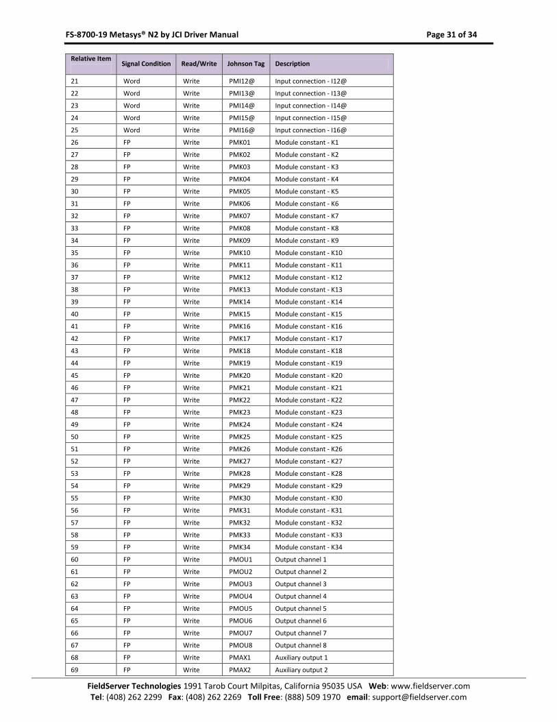
Relative Item
Signal Condition Read/Write Johnson Tag Description
21 Word Write PMI12@ Input connection - I12@
22 Word Write PMI13@ Input connection - I13@
23 Word Write PMI14@ Input connection - I14@
24 Word Write PMI15@ Input connection - I15@
25 Word Write PMI16@ Input connection - I16@
26 FP Write PMK01 Module constant - K1
27 FP Write PMK02 Module constant - K2
28 FP Write PMK03 Module constant - K3
29 FP Write PMK04 Module constant - K4
30 FP Write PMK05 Module constant - K5
31 FP Write PMK06 Module constant - K6
32 FP Write PMK07 Module constant - K7
33 FP Write PMK08 Module constant - K8
34 FP Write PMK09 Module constant - K9
35 FP Write PMK10 Module constant - K10
36 FP Write PMK11 Module constant - K11
37 FP Write PMK12 Module constant - K12
38 FP Write PMK13 Module constant - K13
39 FP Write PMK14 Module constant - K14
40 FP Write PMK15 Module constant - K15
41 FP Write PMK16 Module constant - K16
42 FP Write PMK17 Module constant - K17
43 FP Write PMK18 Module constant - K18
44 FP Write PMK19 Module constant - K19
45 FP Write PMK20 Module constant - K20
46 FP Write PMK21 Module constant - K21
47 FP Write PMK22 Module constant - K22
48 FP Write PMK23 Module constant - K23
49 FP Write PMK24 Module constant - K24
50 FP Write PMK25 Module constant - K25
51 FP Write PMK26 Module constant - K26
52 FP Write PMK27 Module constant - K27
53 FP Write PMK28 Module constant - K28
54 FP Write PMK29 Module constant - K29
55 FP Write PMK30 Module constant - K30
56 FP Write PMK31 Module constant - K31
57 FP Write PMK32 Module constant - K32
58 FP Write PMK33 Module constant - K33
59 FP Write PMK34 Module constant - K34
60 FP Write PMOU1 Output channel 1
61 FP Write PMOU2 Output channel 2
62 FP Write PMOU3 Output channel 3
63 FP Write PMOU4 Output channel 4
64 FP Write PMOU5 Output channel 5
65 FP Write PMOU6 Output channel 6
66 FP Write PMOU7 Output channel 7
67 FP Write PMOU8 Output channel 8
68 FP Write PMAX1 Auxiliary output 1
69 FP Write PMAX2 Auxiliary output 2
FS-8700-19 Metasys® N2 by JCI Driver Manual Page 32 of 34
FieldServer Technologies 1991 Tarob Court Milpitas, California 95035 USA Web: www.fieldserver.com Tel: (408) 262 2299 Fax: (408) 262 2269 Toll Free: (888) 509 1970 email: [email protected]
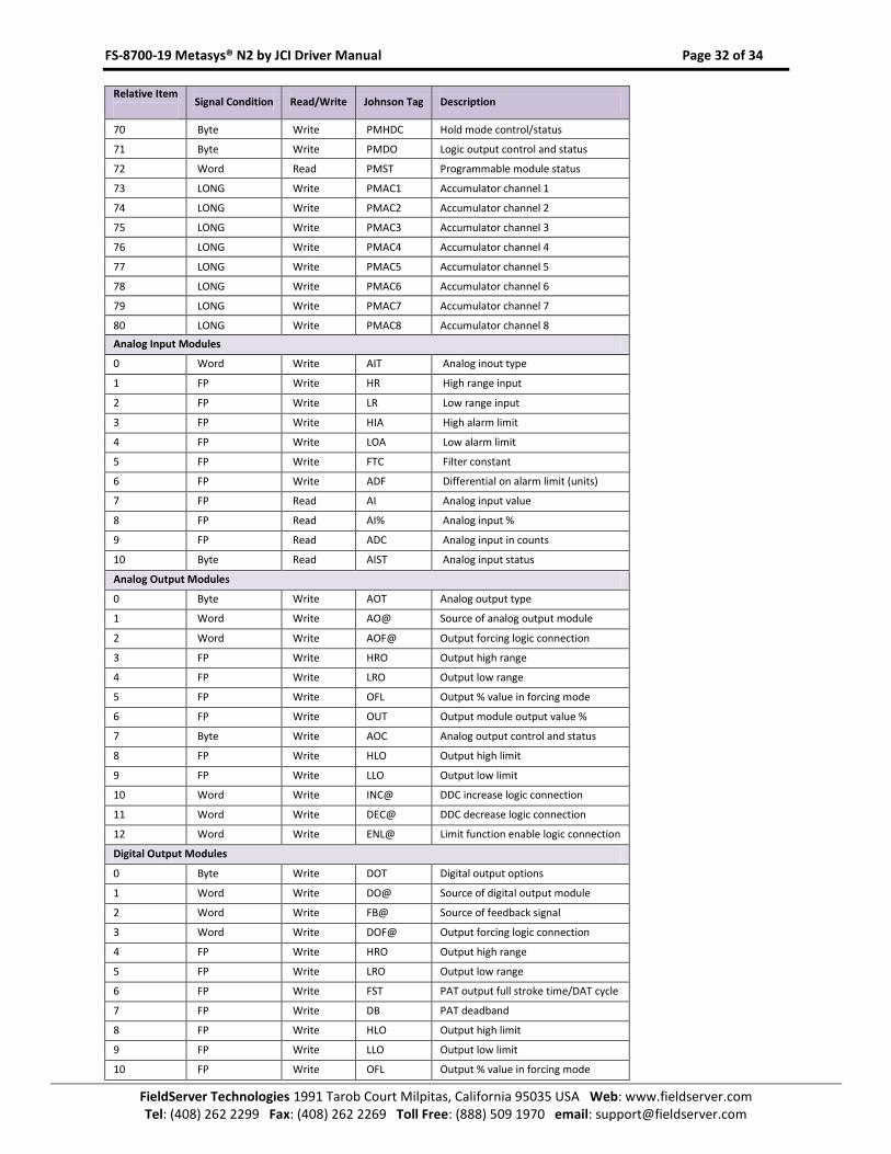
Relative Item
Signal Condition Read/Write Johnson Tag Description
70 Byte Write PMHDC Hold mode control/status
71 Byte Write PMDO Logic output control and status
72 Word Read PMST Programmable module status
73 LONG Write PMAC1 Accumulator channel 1
74 LONG Write PMAC2 Accumulator channel 2
75 LONG Write PMAC3 Accumulator channel 3
76 LONG Write PMAC4 Accumulator channel 4
77 LONG Write PMAC5 Accumulator channel 5
78 LONG Write PMAC6 Accumulator channel 6
79 LONG Write PMAC7 Accumulator channel 7
80 LONG Write PMAC8 Accumulator channel 8
Analog Input Modules
0 Word Write AIT Analog inout type
1 FP Write HR High range input
2 FP Write LR Low range input
3 FP Write HIA High alarm limit
4 FP Write LOA Low alarm limit
5 FP Write FTC Filter constant
6 FP Write ADF Differential on alarm limit (units)
7 FP Read AI Analog input value
8 FP Read AI% Analog input %
9 FP Read ADC Analog input in counts
10 Byte Read AIST Analog input status
Analog Output Modules
0 Byte Write AOT Analog output type
1 Word Write AO@ Source of analog output module
2 Word Write AOF@ Output forcing logic connection
3 FP Write HRO Output high range
4 FP Write LRO Output low range
5 FP Write OFL Output % value in forcing mode
6 FP Write OUT Output module output value %
7 Byte Write AOC Analog output control and status
8 FP Write HLO Output high limit
9 FP Write LLO Output low limit
10 Word Write INC@ DDC increase logic connection
11 Word Write DEC@ DDC decrease logic connection
12 Word Write ENL@ Limit function enable logic connection
Digital Output Modules
0 Byte Write DOT Digital output options
1 Word Write DO@ Source of digital output module
2 Word Write FB@ Source of feedback signal
3 Word Write DOF@ Output forcing logic connection
4 FP Write HRO Output high range
5 FP Write LRO Output low range
6 FP Write FST PAT output full stroke time/DAT cycle
7 FP Write DB PAT deadband
8 FP Write HLO Output high limit
9 FP Write LLO Output low limit
10 FP Write OFL Output % value in forcing mode
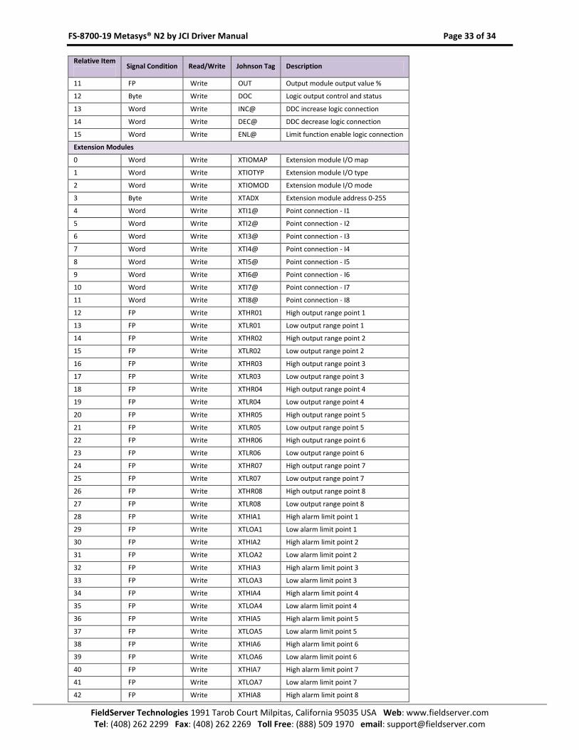
FS-8700-19 Metasys® N2 by JCI Driver Manual Page 33 of 34
FieldServer Technologies 1991 Tarob Court Milpitas, California 95035 USA Web: www.fieldserver.com Tel: (408) 262 2299 Fax: (408) 262 2269 Toll Free: (888) 509 1970 email: [email protected]
Relative Item
Signal Condition Read/Write Johnson Tag Description
11 FP Write OUT Output module output value %
12 Byte Write DOC Logic output control and status
13 Word Write INC@ DDC increase logic connection
14 Word Write DEC@ DDC decrease logic connection
15 Word Write ENL@ Limit function enable logic connection
Extension Modules
0 Word Write XTIOMAP Extension module I/O map
1 Word Write XTIOTYP Extension module I/O type
2 Word Write XTIOMOD Extension module I/O mode
3 Byte Write XTADX Extension module address 0-255
4 Word Write XTI1@ Point connection - I1
5 Word Write XTI2@ Point connection - I2
6 Word Write XTI3@ Point connection - I3
7 Word Write XTI4@ Point connection - I4
8 Word Write XTI5@ Point connection - I5
9 Word Write XTI6@ Point connection - I6
10 Word Write XTI7@ Point connection - I7
11 Word Write XTI8@ Point connection - I8
12 FP Write XTHR01 High output range point 1
13 FP Write XTLR01 Low output range point 1
14 FP Write XTHR02 High output range point 2
15 FP Write XTLR02 Low output range point 2
16 FP Write XTHR03 High output range point 3
17 FP Write XTLR03 Low output range point 3
18 FP Write XTHR04 High output range point 4
19 FP Write XTLR04 Low output range point 4
20 FP Write XTHR05 High output range point 5
21 FP Write XTLR05 Low output range point 5
22 FP Write XTHR06 High output range point 6
23 FP Write XTLR06 Low output range point 6
24 FP Write XTHR07 High output range point 7
25 FP Write XTLR07 Low output range point 7
26 FP Write XTHR08 High output range point 8
27 FP Write XTLR08 Low output range point 8
28 FP Write XTHIA1 High alarm limit point 1
29 FP Write XTLOA1 Low alarm limit point 1
30 FP Write XTHIA2 High alarm limit point 2
31 FP Write XTLOA2 Low alarm limit point 2
32 FP Write XTHIA3 High alarm limit point 3
33 FP Write XTLOA3 Low alarm limit point 3
34 FP Write XTHIA4 High alarm limit point 4
35 FP Write XTLOA4 Low alarm limit point 4
36 FP Write XTHIA5 High alarm limit point 5
37 FP Write XTLOA5 Low alarm limit point 5
38 FP Write XTHIA6 High alarm limit point 6
39 FP Write XTLOA6 Low alarm limit point 6
40 FP Write XTHIA7 High alarm limit point 7
41 FP Write XTLOA7 Low alarm limit point 7
42 FP Write XTHIA8 High alarm limit point 8
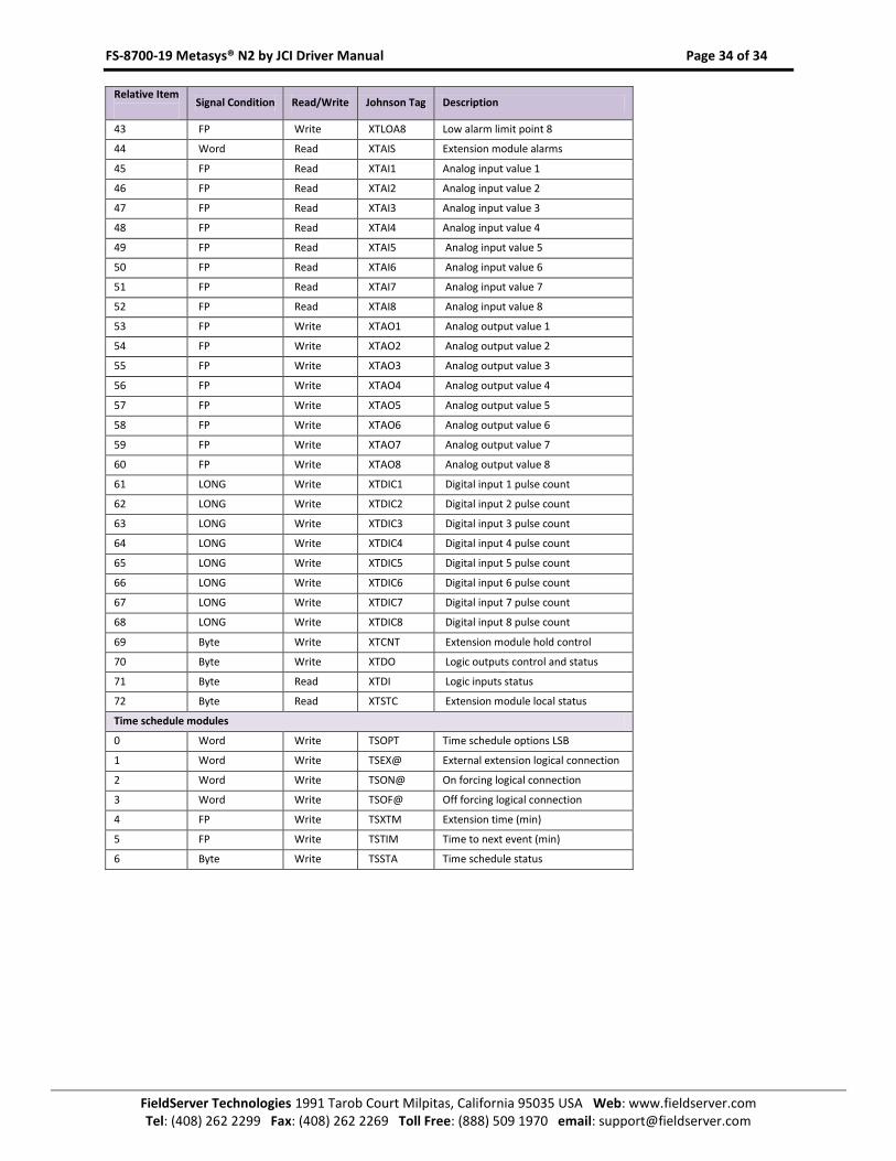
FS-8700-19 Metasys® N2 by JCI Driver Manual Page 34 of 34
FieldServer Technologies 1991 Tarob Court Milpitas, California 95035 USA Web: www.fieldserver.com Tel: (408) 262 2299 Fax: (408) 262 2269 Toll Free: (888) 509 1970 email: [email protected]
Relative Item
Signal Condition Read/Write Johnson Tag Description
43 FP Write XTLOA8 Low alarm limit point 8
44 Word Read XTAIS Extension module alarms
45 FP Read XTAI1 Analog input value 1
46 FP Read XTAI2 Analog input value 2
47 FP Read XTAI3 Analog input value 3
48 FP Read XTAI4 Analog input value 4
49 FP Read XTAI5 Analog input value 5
50 FP Read XTAI6 Analog input value 6
51 FP Read XTAI7 Analog input value 7
52 FP Read XTAI8 Analog input value 8
53 FP Write XTAO1 Analog output value 1
54 FP Write XTAO2 Analog output value 2
55 FP Write XTAO3 Analog output value 3
56 FP Write XTAO4 Analog output value 4
57 FP Write XTAO5 Analog output value 5
58 FP Write XTAO6 Analog output value 6
59 FP Write XTAO7 Analog output value 7
60 FP Write XTAO8 Analog output value 8
61 LONG Write XTDIC1 Digital input 1 pulse count
62 LONG Write XTDIC2 Digital input 2 pulse count
63 LONG Write XTDIC3 Digital input 3 pulse count
64 LONG Write XTDIC4 Digital input 4 pulse count
65 LONG Write XTDIC5 Digital input 5 pulse count
66 LONG Write XTDIC6 Digital input 6 pulse count
67 LONG Write XTDIC7 Digital input 7 pulse count
68 LONG Write XTDIC8 Digital input 8 pulse count
69 Byte Write XTCNT Extension module hold control
70 Byte Write XTDO Logic outputs control and status
71 Byte Read XTDI Logic inputs status
72 Byte Read XTSTC Extension module local status
Time schedule modules
0 Word Write TSOPT Time schedule options LSB
1 Word Write TSEX@ External extension logical connection
2 Word Write TSON@ On forcing logical connection
3 Word Write TSOF@ Off forcing logical connection
4 FP Write TSXTM Extension time (min)
5 FP Write TSTIM Time to next event (min)
6 Byte Write TSSTA Time schedule status