driver manual - prosoft technology...the panel must output messages in ascii format in english. this...
TRANSCRIPT
Driver Version: 1.00
Document Revision: 2
A Sierra Monitor Company
APPLICABILITY & EFFECTIVITY
Effective for all systems manufactured after February 2010
Driver Manual
(Supplement to the FieldServer Instruction Manual)
FS-8700-137 Hochiki FireNET
FS-8700-137 Hochiki Manual Table of Contents
FieldServer Technologies 1991 Tarob Court Milpitas, California 95035 USA Web: www.fieldserver.com
Tel: (408) 262 2299 Fax: (408) 262 2269 Toll Free: (888) 509 1970 email: [email protected]
TABLE OF CONTENTS
1 Hochiki Description ........................................................................................................................................ 3
2 Driver Scope of Supply ................................................................................................................................... 4
2.1 Supplied by FieldServer Technologies for this driver ..................................................................................... 4
2.2 Provided by the Supplier of 3rd
Party Equipment .......................................................................................... 4
2.2.1 Required 3rd
Party Hardware ................................................................................................................. 4
3 Hardware Connections ................................................................................................................................... 5
3.1 Connection to FS-X30 .................................................................................................................................... 5
3.2 Connection to FS-X20, FS-X40 ........................................................................................................................ 5
4 Data Array Parameters ................................................................................................................................... 6
5 Configuring the FieldServer as a Hochiki Client .............................................................................................. 7
5.1 Client Side Connection Parameters ............................................................................................................... 7
5.2 Client Side Node Parameters ......................................................................................................................... 8
5.3 Client Side Map Descriptor Parameters ......................................................................................................... 9
5.3.1 FieldServer Related Map Descriptor Parameters ................................................................................... 9
5.3.2 Driver Related Map Descriptor Parameters ........................................................................................... 9
5.4 Panel Map Descriptor Examples. ................................................................................................................. 10
5.5 Loop Map Descriptor Examples. .................................................................................................................. 11
5.6 Communication Bus Map Descriptor Example. ........................................................................................... 12
Appendix A. Useful Features ................................................................................................................................ 13
Appendix A.1. Data Synchronisation ....................................................................................................................... 13
Appendix B. Troubleshooting ............................................................................................................................... 14
Appendix B.1. Heartbeat data ................................................................................................................................. 14
Appendix B.2. Using HyperTerminal to address Communication Problems............................................................ 14
Appendix C. Reference ......................................................................................................................................... 15
Appendix C.1. Data Types ........................................................................................................................................ 15
Appendix C.1.1. Heartbeat: .............................................................................................................................. 15
Appendix C.1.2. Troubles: ................................................................................................................................. 15
Appendix C.1.3. Alarms: ................................................................................................................................... 15
Appendix C.1.4. Panel Troubles: ....................................................................................................................... 16
Appendix C.2. Event number and description Table ............................................................................................... 16
Appendix C.3. Message Types Recognised by the Driver ........................................................................................ 17
FS-8700-137Hochiki FireNET Manual Page 3 of 17
FieldServer Technologies 1991 Tarob Court Milpitas, California 95035 USA Web: www.fieldserver.com
Tel: (408) 262 2299 Fax: (408) 262 2269 Toll Free: (888) 509 1970 email: [email protected]
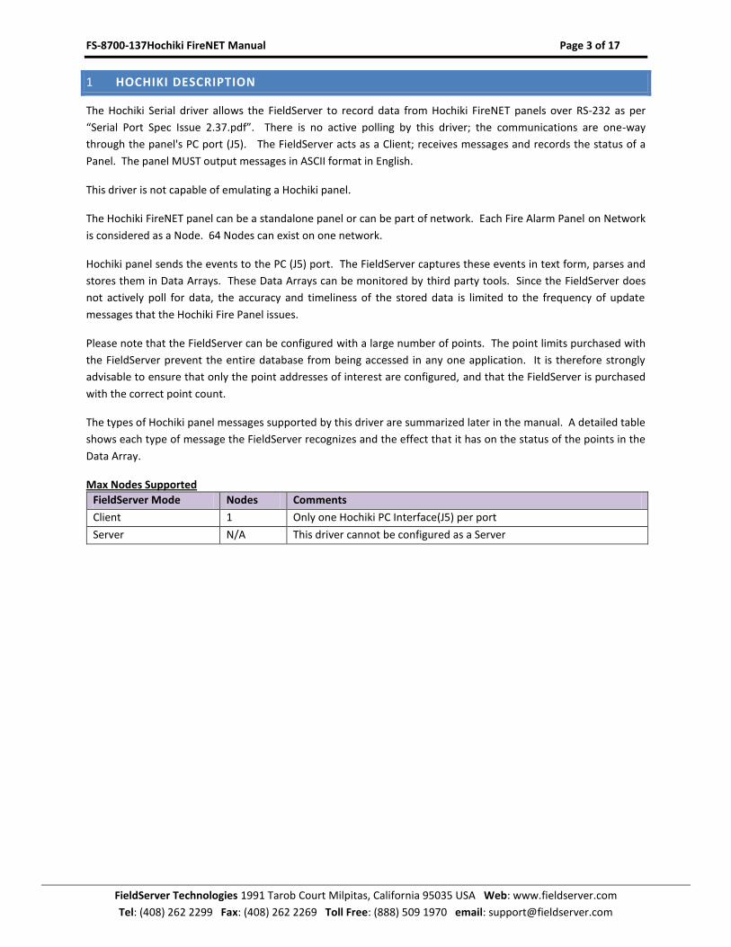
1 HOCHIKI DESCRIPTION
The Hochiki Serial driver allows the FieldServer to record data from Hochiki FireNET panels over RS-232 as per
“Serial Port Spec Issue 2.37.pdf”. There is no active polling by this driver; the communications are one-way
through the panel's PC port (J5). The FieldServer acts as a Client; receives messages and records the status of a
Panel. The panel MUST output messages in ASCII format in English.
This driver is not capable of emulating a Hochiki panel.
The Hochiki FireNET panel can be a standalone panel or can be part of network. Each Fire Alarm Panel on Network
is considered as a Node. 64 Nodes can exist on one network.
Hochiki panel sends the events to the PC (J5) port. The FieldServer captures these events in text form, parses and
stores them in Data Arrays. These Data Arrays can be monitored by third party tools. Since the FieldServer does
not actively poll for data, the accuracy and timeliness of the stored data is limited to the frequency of update
messages that the Hochiki Fire Panel issues.
Please note that the FieldServer can be configured with a large number of points. The point limits purchased with
the FieldServer prevent the entire database from being accessed in any one application. It is therefore strongly
advisable to ensure that only the point addresses of interest are configured, and that the FieldServer is purchased
with the correct point count.
The types of Hochiki panel messages supported by this driver are summarized later in the manual. A detailed table
shows each type of message the FieldServer recognizes and the effect that it has on the status of the points in the
Data Array.
Max Nodes Supported
FieldServer Mode Nodes Comments
Client 1 Only one Hochiki PC Interface(J5) per port
Server N/A This driver cannot be configured as a Server
FS-8700-137Hochiki FireNET Manual Page 4 of 17
FieldServer Technologies 1991 Tarob Court Milpitas, California 95035 USA Web: www.fieldserver.com
Tel: (408) 262 2299 Fax: (408) 262 2269 Toll Free: (888) 509 1970 email: [email protected]
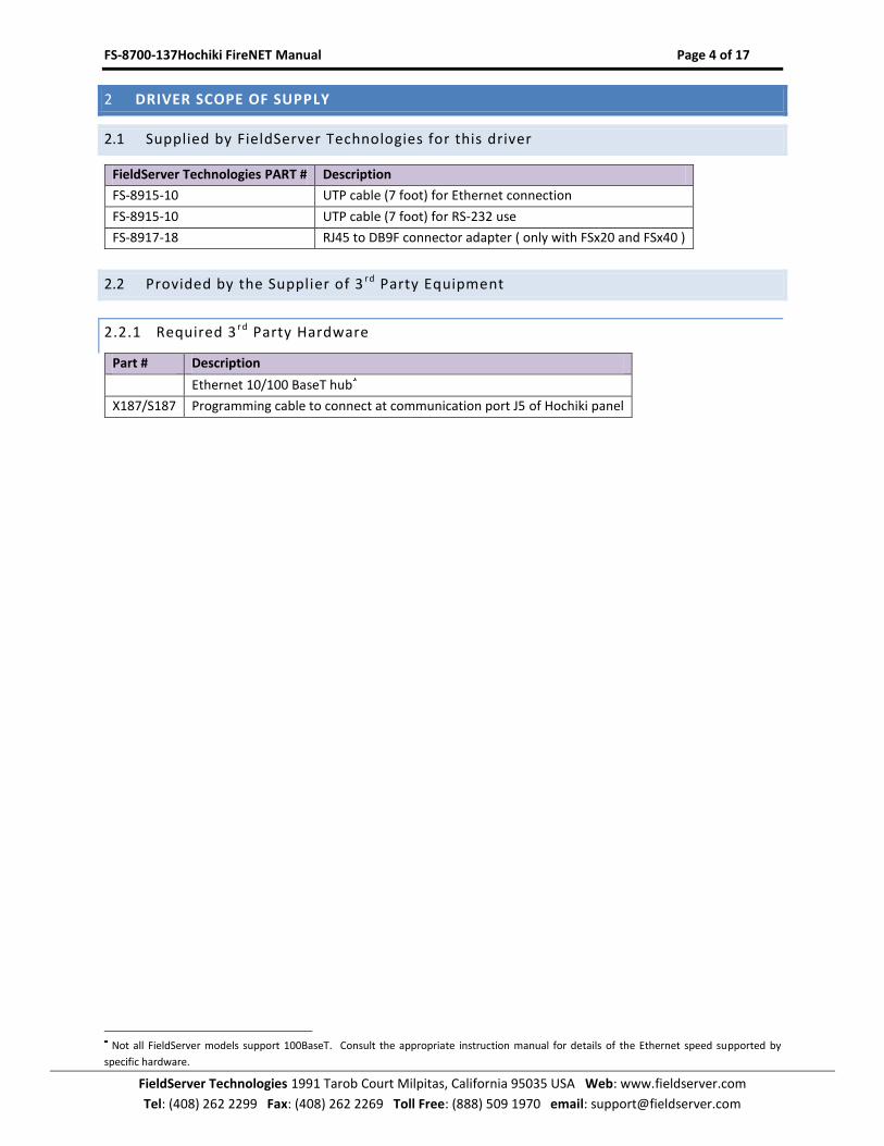
2 DRIVER SCOPE OF SUPPLY
2.1 Supplied by FieldServer Technologies for this driver
FieldServer Technologies PART # Description
FS-8915-10 UTP cable (7 foot) for Ethernet connection
FS-8915-10 UTP cable (7 foot) for RS-232 use
FS-8917-18 RJ45 to DB9F connector adapter ( only with FSx20 and FSx40 )
2.2 Provided by the Supplier of 3 rd Party Equipment
2.2.1 Required 3 r d Party Hardware
Part # Description
Ethernet 10/100 BaseT hub
X187/S187 Programming cable to connect at communication port J5 of Hochiki panel
Not all FieldServer models support 100BaseT. Consult the appropriate instruction manual for details of the Ethernet speed supported by
specific hardware.
FS-8700-137Hochiki FireNET Manual Page 5 of 17
FieldServer Technologies 1991 Tarob Court Milpitas, California 95035 USA Web: www.fieldserver.com
Tel: (408) 262 2299 Fax: (408) 262 2269 Toll Free: (888) 509 1970 email: [email protected]
3 HARDWARE CONNECTIONS
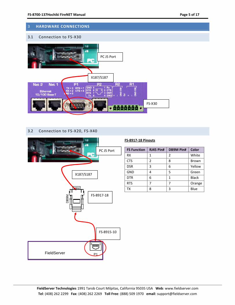
3.1 Connection to FS-X30
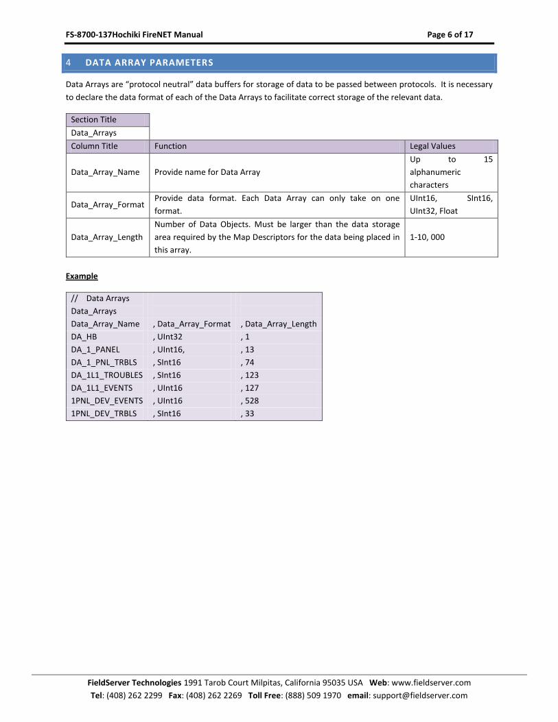
3.2 Connection to FS-X20, FS-X40
FieldServer P1
18
FS-8917-18 Pinouts
FS Function RJ45 Pin# DB9M Pin# Color
RX 1 2 White
CTS 2 8 Brown
DSR 3 6 Yellow
GND 4 5 Green
DTR 6 1 Black
RTS 7 7 Orange
TX 8 3 Blue
PC J5 Port
FS-X30
X187/S187
PC J5 Port
X187/S187
FS-8917-18
DB
9M
FS-8915-10
FS-8700-137Hochiki FireNET Manual Page 6 of 17
FieldServer Technologies 1991 Tarob Court Milpitas, California 95035 USA Web: www.fieldserver.com
Tel: (408) 262 2299 Fax: (408) 262 2269 Toll Free: (888) 509 1970 email: [email protected]
4 DATA ARRAY PARAMETERS
Data Arrays are “protocol neutral” data buffers for storage of data to be passed between protocols. It is necessary
to declare the data format of each of the Data Arrays to facilitate correct storage of the relevant data.
Section Title
Data_Arrays
Column Title Function Legal Values
Data_Array_Name Provide name for Data Array
Up to 15
alphanumeric
characters
Data_Array_Format Provide data format. Each Data Array can only take on one
format.
UInt16, SInt16,
UInt32, Float
Data_Array_Length
Number of Data Objects. Must be larger than the data storage
area required by the Map Descriptors for the data being placed in
this array.
1-10, 000
Example
// Data Arrays
Data_Arrays
Data_Array_Name , Data_Array_Format , Data_Array_Length
DA_HB , UInt32 , 1
DA_1_PANEL , UInt16, , 13
DA_1_PNL_TRBLS , SInt16 , 74
DA_1L1_TROUBLES , SInt16 , 123
DA_1L1_EVENTS , UInt16 , 127
1PNL_DEV_EVENTS , UInt16 , 528
1PNL_DEV_TRBLS , SInt16 , 33
FS-8700-137Hochiki FireNET Manual Page 7 of 17
FieldServer Technologies 1991 Tarob Court Milpitas, California 95035 USA Web: www.fieldserver.com
Tel: (408) 262 2299 Fax: (408) 262 2269 Toll Free: (888) 509 1970 email: [email protected]
5 CONFIGURING THE FIELDSERVER AS A HOCHIKI CLIENT
For a detailed discussion on FieldServer configuration, please refer to the FieldServer Configuration Manual. The
information that follows describes how to expand upon the factory defaults provided in the configuration files
included with the FieldServer (See “.csv” sample files provided with the FieldServer).
This section documents and describes the parameters necessary for configuring the FieldServer to communicate
with a Hochiki FireNET panel.
The configuration file tells the FieldServer about its interfaces, and the routing of data required. In order to enable
the FieldServer for Hochiki FireNet communications, the driver independent FieldServer buffers need to be
declared in the “Data Arrays” section, the destination device addresses need to be declared in the “Client Side
Nodes” section, and the data required from the servers needs to be mapped in the “Client Side Map Descriptors”
section. Details on how to do this can be found below.
Note that in the tables, * indicates an optional parameter, with the bold legal value being the default.
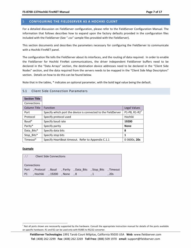
5.1 Client Side Connection Parameters
Section Title
Connections
Column Title Function Legal Values
Port Specify which port the device is connected to the FieldServer P1-P8, R1-R21
Protocol Specify protocol used Hochiki
Baud* Specify baud rate 19200
Parity* Specify parity None
Data_Bits* Specify data bits 8
Stop_Bits* Specify stop bits 1
Timeout* Specify HeartBeat timeout. Refer to Appendix C.1.1 0-3600s, 20s
Example
// Client Side Connections
Connections
Port , Protocol , Baud , Parity , Data_Bits , Stop_Bits , Timeout
P1 , Hochiki , 19200 , None , 8 , 1 , 20s
1 Not all ports shown are necessarily supported by the hardware. Consult the appropriate Instruction manual for details of the ports available
on specific hardware. R1 and R2 can be used only with RS485 to RS232 converter.
FS-8700-137Hochiki FireNET Manual Page 8 of 17
FieldServer Technologies 1991 Tarob Court Milpitas, California 95035 USA Web: www.fieldserver.com
Tel: (408) 262 2299 Fax: (408) 262 2269 Toll Free: (888) 509 1970 email: [email protected]
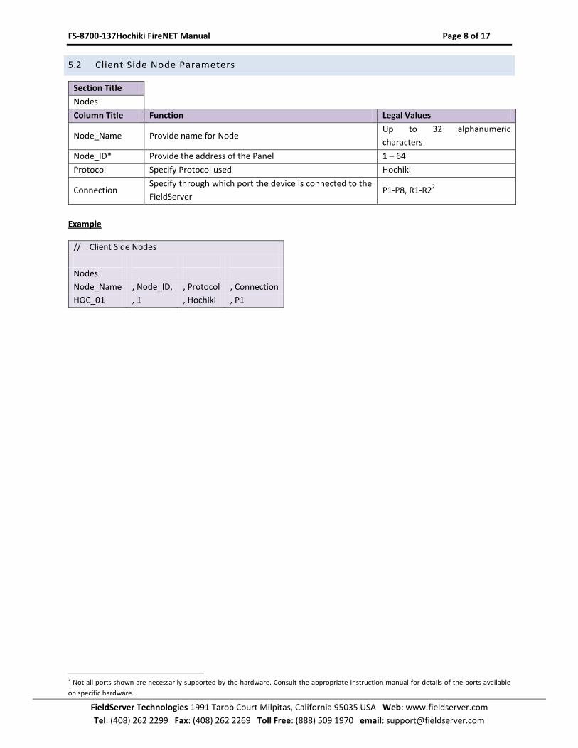
5.2 Client Side Node Parameters
Section Title
Nodes
Column Title Function Legal Values
Node_Name Provide name for Node Up to 32 alphanumeric
characters
Node_ID* Provide the address of the Panel 1 – 64
Protocol Specify Protocol used Hochiki
Connection Specify through which port the device is connected to the
FieldServer P1-P8, R1-R2
2
Example
// Client Side Nodes
Nodes
Node_Name , Node_ID, , Protocol , Connection
HOC_01 , 1 , Hochiki , P1
2 Not all ports shown are necessarily supported by the hardware. Consult the appropriate Instruction manual for details of the ports available
on specific hardware.
FS-8700-137Hochiki FireNET Manual Page 9 of 17
FieldServer Technologies 1991 Tarob Court Milpitas, California 95035 USA Web: www.fieldserver.com
Tel: (408) 262 2299 Fax: (408) 262 2269 Toll Free: (888) 509 1970 email: [email protected]
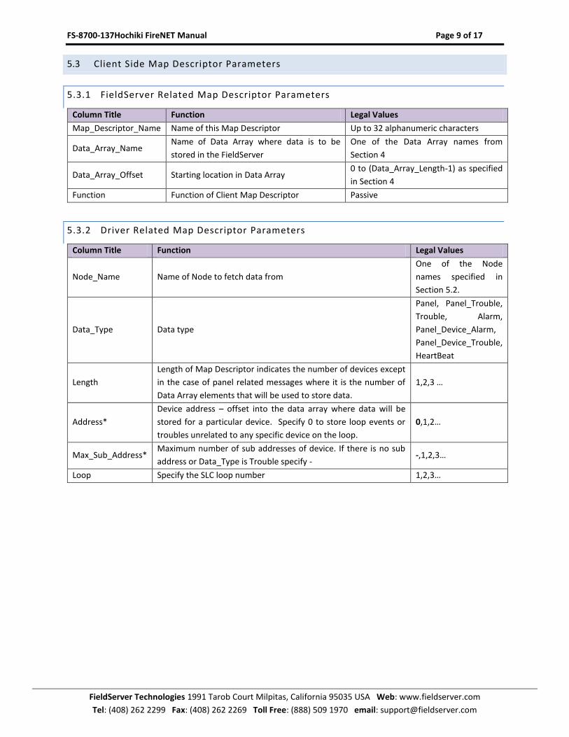
5.3 Client Side Map Descriptor Parameters
5.3.1 FieldServer Related Map Descriptor Parameters
Column Title Function Legal Values
Map_Descriptor_Name Name of this Map Descriptor Up to 32 alphanumeric characters
Data_Array_Name Name of Data Array where data is to be
stored in the FieldServer
One of the Data Array names from
Section 4
Data_Array_Offset Starting location in Data Array 0 to (Data_Array_Length-1) as specified
in Section 4
Function Function of Client Map Descriptor Passive
5.3.2 Driver Related Map Descriptor Parameters
Column Title Function Legal Values
Node_Name Name of Node to fetch data from
One of the Node
names specified in
Section 5.2.
Data_Type Data type
Panel, Panel_Trouble,
Trouble, Alarm,
Panel_Device_Alarm,
Panel_Device_Trouble,
HeartBeat
Length
Length of Map Descriptor indicates the number of devices except
in the case of panel related messages where it is the number of
Data Array elements that will be used to store data.
1,2,3 …
Address*
Device address – offset into the data array where data will be
stored for a particular device. Specify 0 to store loop events or
troubles unrelated to any specific device on the loop.
0,1,2…
Max_Sub_Address* Maximum number of sub addresses of device. If there is no sub
address or Data_Type is Trouble specify - -,1,2,3…
Loop Specify the SLC loop number 1,2,3…
FS-8700-137Hochiki FireNET Manual Page 10 of 17
FieldServer Technologies 1991 Tarob Court Milpitas, California 95035 USA Web: www.fieldserver.com
Tel: (408) 262 2299 Fax: (408) 262 2269 Toll Free: (888) 509 1970 email: [email protected]
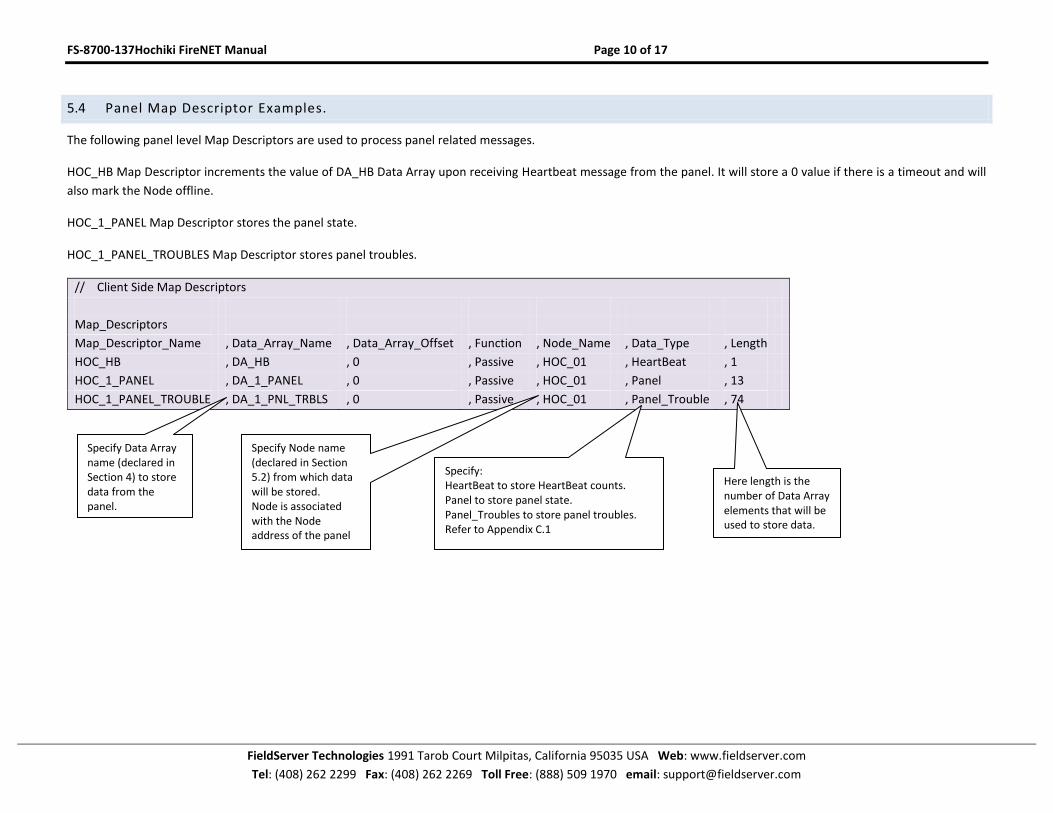
5.4 Panel Map Descriptor Examples.
The following panel level Map Descriptors are used to process panel related messages.
HOC_HB Map Descriptor increments the value of DA_HB Data Array upon receiving Heartbeat message from the panel. It will store a 0 value if there is a timeout and will
also mark the Node offline.
HOC_1_PANEL Map Descriptor stores the panel state.
HOC_1_PANEL_TROUBLES Map Descriptor stores panel troubles.
// Client Side Map Descriptors
Map_Descriptors
Map_Descriptor_Name , Data_Array_Name , Data_Array_Offset , Function , Node_Name , Data_Type , Length
HOC_HB , DA_HB , 0 , Passive , HOC_01 , HeartBeat , 1
HOC_1_PANEL , DA_1_PANEL , 0 , Passive , HOC_01 , Panel , 13
HOC_1_PANEL_TROUBLE , DA_1_PNL_TRBLS , 0 , Passive , HOC_01 , Panel_Trouble , 74
Specify Data Array name (declared in Section 4) to store data from the panel.
Specify Node name (declared in Section 5.2) from which data will be stored. Node is associated with the Node address of the panel
Specify: HeartBeat to store HeartBeat counts. Panel to store panel state. Panel_Troubles to store panel troubles. Refer to Appendix C.1
Here length is the number of Data Array elements that will be used to store data.
FS-8700-137Hochiki FireNET Manual Page 11 of 17
FieldServer Technologies 1991 Tarob Court Milpitas, California 95035 USA Web: www.fieldserver.com
Tel: (408) 262 2299 Fax: (408) 262 2269 Toll Free: (888) 509 1970 email: [email protected]
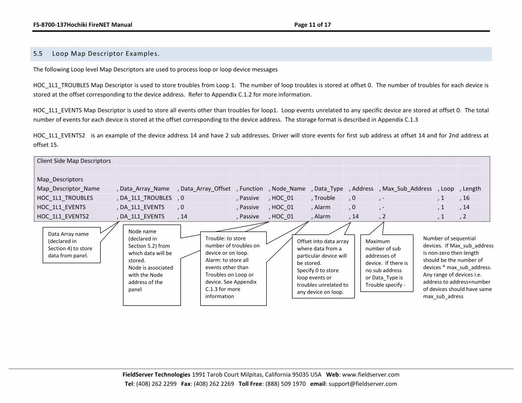
5.5 Loop Map Descriptor Examples.
The following Loop level Map Descriptors are used to process loop or loop device messages
HOC_1L1_TROUBLES Map Descriptor is used to store troubles from Loop 1. The number of loop troubles is stored at offset 0. The number of troubles for each device is
stored at the offset corresponding to the device address. Refer to Appendix C.1.2 for more information.
HOC_1L1_EVENTS Map Descriptor is used to store all events other than troubles for loop1. Loop events unrelated to any specific device are stored at offset 0. The total
number of events for each device is stored at the offset corresponding to the device address. The storage format is described in Appendix C.1.3
HOC_1L1_EVENTS2 is an example of the device address 14 and have 2 sub addresses. Driver will store events for first sub address at offset 14 and for 2nd address at
offset 15.
Client Side Map Descriptors
Map_Descriptors
Map_Descriptor_Name , Data_Array_Name , Data_Array_Offset , Function , Node_Name , Data_Type , Address , Max_Sub_Address , Loop , Length
HOC_1L1_TROUBLES , DA_1L1_TROUBLES , 0 , Passive , HOC_01 , Trouble , 0 , - , 1 , 16
HOC_1L1_EVENTS , DA_1L1_EVENTS , 0 , Passive , HOC_01 , Alarm , 0 , - , 1 , 14
HOC_1L1_EVENTS2 , DA_1L1_EVENTS , 14 , Passive , HOC_01 , Alarm , 14 , 2 , 1 , 2
Data Array name (declared in Section 4) to store data from panel.
Node name (declared in Section 5.2) from which data will be stored. Node is associated with the Node address of the panel
Trouble: to store number of troubles on device or on loop. Alarm: to store all events other than Troubles on Loop or device. See Appendix C.1.3 for more information
Offset into data array where data from a particular device will be stored. Specify 0 to store loop events or troubles unrelated to any device on loop.
Maximum number of sub addresses of device. If there is no sub address or Data_Type is Trouble specify -
Number of sequential devices. If Max_sub_address is non-zero then length should be the number of devices * max_sub_address. Any range of devices i.e. address to address+number of devices should have same max_sub_adress
FS-8700-137Hochiki FireNET Manual Page 12 of 17
FieldServer Technologies 1991 Tarob Court Milpitas, California 95035 USA Web: www.fieldserver.com
Tel: (408) 262 2299 Fax: (408) 262 2269 Toll Free: (888) 509 1970 email: [email protected]
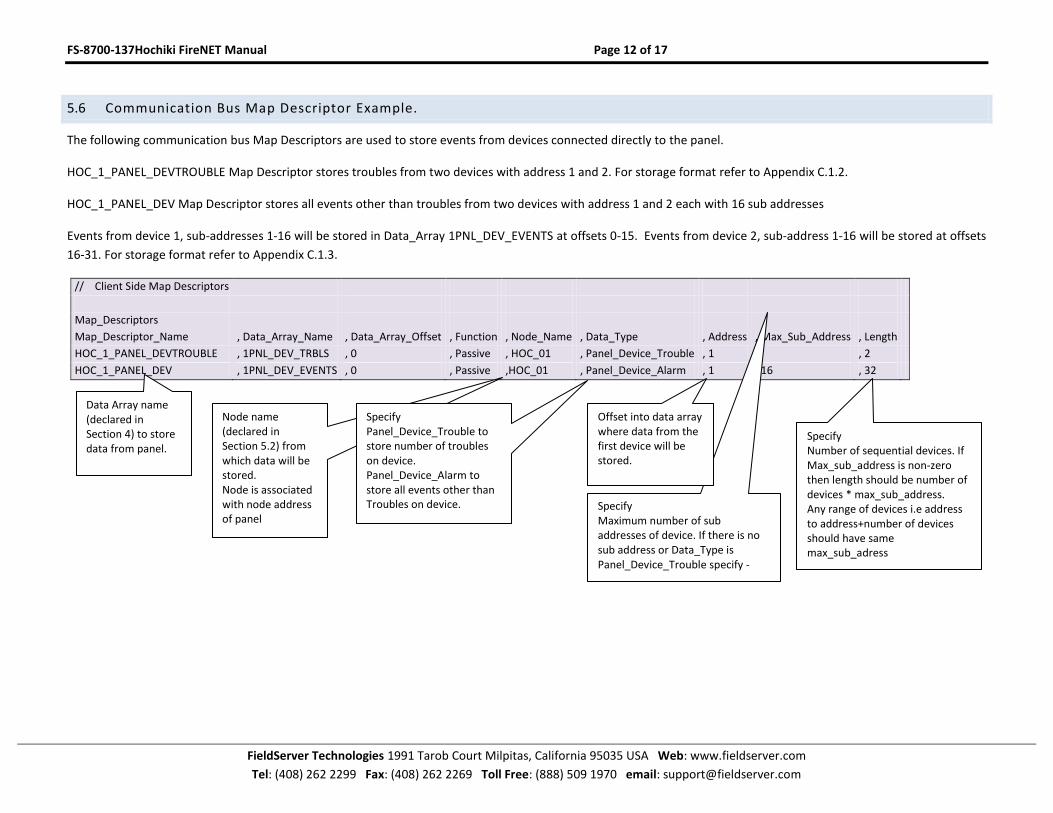
5.6 Communication Bus Map Descriptor Example.
The following communication bus Map Descriptors are used to store events from devices connected directly to the panel.
HOC_1_PANEL_DEVTROUBLE Map Descriptor stores troubles from two devices with address 1 and 2. For storage format refer to Appendix C.1.2.
HOC_1_PANEL_DEV Map Descriptor stores all events other than troubles from two devices with address 1 and 2 each with 16 sub addresses
Events from device 1, sub-addresses 1-16 will be stored in Data_Array 1PNL_DEV_EVENTS at offsets 0-15. Events from device 2, sub-address 1-16 will be stored at offsets
16-31. For storage format refer to Appendix C.1.3.
// Client Side Map Descriptors
Map_Descriptors
Map_Descriptor_Name , Data_Array_Name , Data_Array_Offset , Function , Node_Name , Data_Type , Address , Max_Sub_Address , Length
HOC_1_PANEL_DEVTROUBLE , 1PNL_DEV_TRBLS , 0 , Passive , HOC_01 , Panel_Device_Trouble , 1 ,- , 2
HOC_1_PANEL_DEV , 1PNL_DEV_EVENTS , 0 , Passive ,HOC_01 , Panel_Device_Alarm , 1 , 16 , 32
Data Array name (declared in Section 4) to store data from panel.
Node name (declared in Section 5.2) from which data will be stored. Node is associated with node address of panel
Specify Panel_Device_Trouble to store number of troubles on device. Panel_Device_Alarm to store all events other than Troubles on device. Specify
Maximum number of sub addresses of device. If there is no sub address or Data_Type is Panel_Device_Trouble specify -
Specify Number of sequential devices. If Max_sub_address is non-zero then length should be number of devices * max_sub_address. Any range of devices i.e address to address+number of devices should have same max_sub_adress
Offset into data array where data from the first device will be stored.
FS-8700-137Hochiki FireNET Manual Page 13 of 17
FieldServer Technologies 1991 Tarob Court Milpitas, California 95035 USA Web: www.fieldserver.com
Tel: (408) 262 2299 Fax: (408) 262 2269 Toll Free: (888) 509 1970 email: [email protected]
Appendix A. USEFUL FEATURES
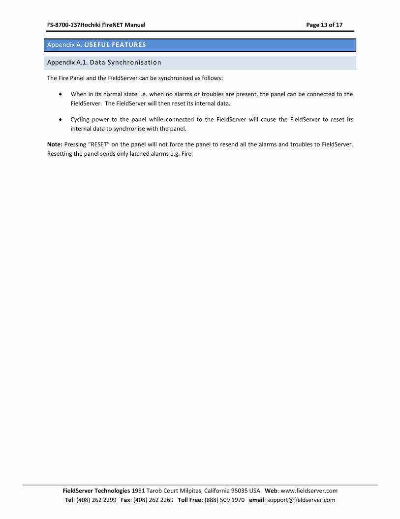
Appendix A.1. Data Synchronisation
The Fire Panel and the FieldServer can be synchronised as follows:
When in its normal state i.e. when no alarms or troubles are present, the panel can be connected to the
FieldServer. The FieldServer will then reset its internal data.
Cycling power to the panel while connected to the FieldServer will cause the FieldServer to reset its
internal data to synchronise with the panel.
Note: Pressing “RESET” on the panel will not force the panel to resend all the alarms and troubles to FieldServer.
Resetting the panel sends only latched alarms e.g. Fire.
FS-8700-137Hochiki FireNET Manual Page 14 of 17
FieldServer Technologies 1991 Tarob Court Milpitas, California 95035 USA Web: www.fieldserver.com
Tel: (408) 262 2299 Fax: (408) 262 2269 Toll Free: (888) 509 1970 email: [email protected]
Appendix B. TROUBLESHOOTING
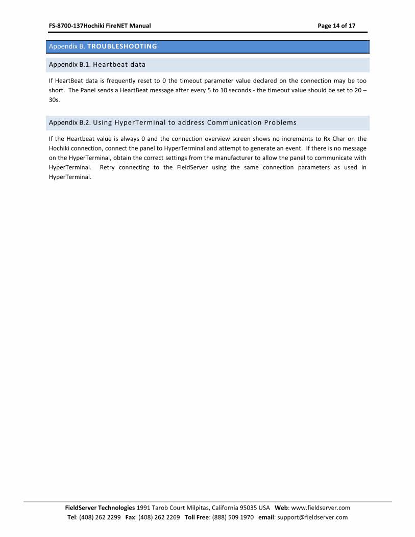
Appendix B.1. Heartbeat data
If HeartBeat data is frequently reset to 0 the timeout parameter value declared on the connection may be too
short. The Panel sends a HeartBeat message after every 5 to 10 seconds - the timeout value should be set to 20 –
30s.
Appendix B.2. Using HyperTerminal to address Communication Problems
If the Heartbeat value is always 0 and the connection overview screen shows no increments to Rx Char on the
Hochiki connection, connect the panel to HyperTerminal and attempt to generate an event. If there is no message
on the HyperTerminal, obtain the correct settings from the manufacturer to allow the panel to communicate with
HyperTerminal. Retry connecting to the FieldServer using the same connection parameters as used in
HyperTerminal.
FS-8700-137Hochiki FireNET Manual Page 15 of 17
FieldServer Technologies 1991 Tarob Court Milpitas, California 95035 USA Web: www.fieldserver.com
Tel: (408) 262 2299 Fax: (408) 262 2269 Toll Free: (888) 509 1970 email: [email protected]
Appendix C. REFERENCE
Appendix C.1. Data Types
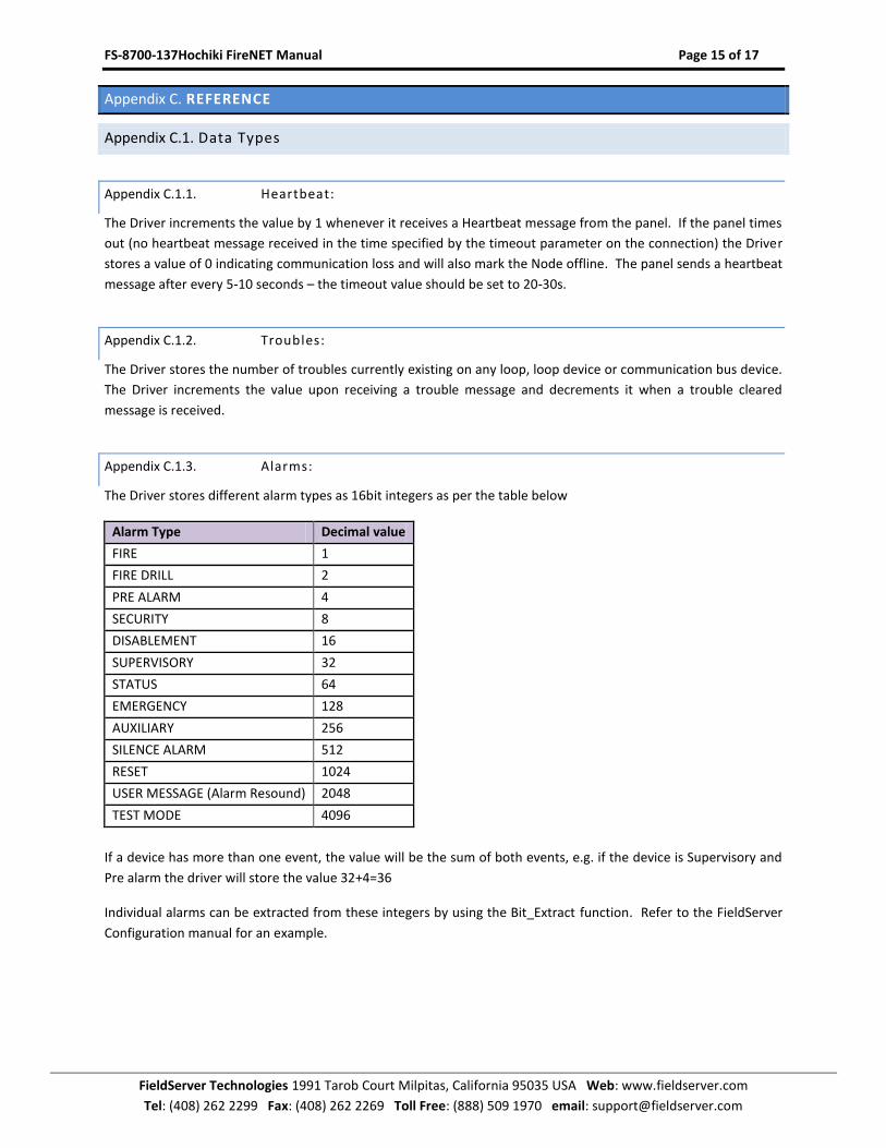
Appendix C.1.1. Heartbeat:
The Driver increments the value by 1 whenever it receives a Heartbeat message from the panel. If the panel times
out (no heartbeat message received in the time specified by the timeout parameter on the connection) the Driver
stores a value of 0 indicating communication loss and will also mark the Node offline. The panel sends a heartbeat
message after every 5-10 seconds – the timeout value should be set to 20-30s.
Appendix C.1.2. Troubles:
The Driver stores the number of troubles currently existing on any loop, loop device or communication bus device.
The Driver increments the value upon receiving a trouble message and decrements it when a trouble cleared
message is received.
Appendix C.1.3. Alarms:
The Driver stores different alarm types as 16bit integers as per the table below
Alarm Type Decimal value
FIRE 1
FIRE DRILL 2
PRE ALARM 4
SECURITY 8
DISABLEMENT 16
SUPERVISORY 32
STATUS 64
EMERGENCY 128
AUXILIARY 256
SILENCE ALARM 512
RESET 1024
USER MESSAGE (Alarm Resound) 2048
TEST MODE 4096
If a device has more than one event, the value will be the sum of both events, e.g. if the device is Supervisory and
Pre alarm the driver will store the value 32+4=36
Individual alarms can be extracted from these integers by using the Bit_Extract function. Refer to the FieldServer
Configuration manual for an example.
FS-8700-137Hochiki FireNET Manual Page 16 of 17
FieldServer Technologies 1991 Tarob Court Milpitas, California 95035 USA Web: www.fieldserver.com
Tel: (408) 262 2299 Fax: (408) 262 2269 Toll Free: (888) 509 1970 email: [email protected]
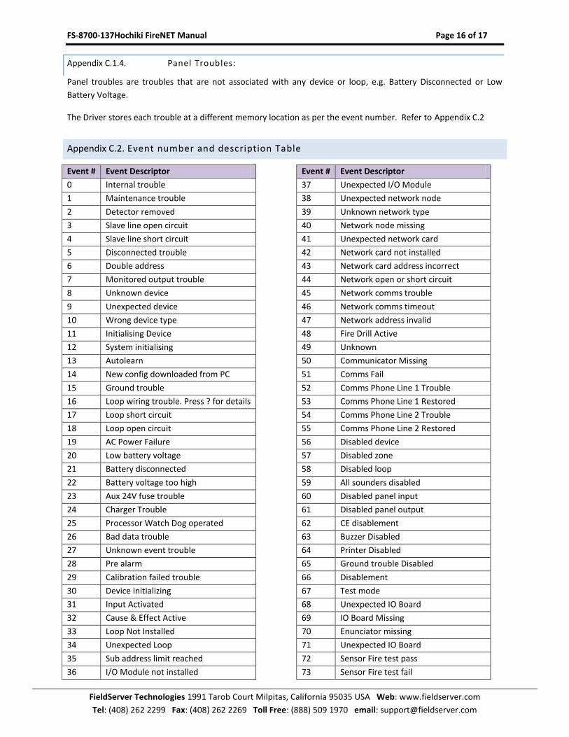
Appendix C.1.4. Panel Troubles:
Panel troubles are troubles that are not associated with any device or loop, e.g. Battery Disconnected or Low
Battery Voltage.
The Driver stores each trouble at a different memory location as per the event number. Refer to Appendix C.2
Appendix C.2. Event number and description Table
Event # Event Descriptor
0 Internal trouble
1 Maintenance trouble
2 Detector removed
3 Slave line open circuit
4 Slave line short circuit
5 Disconnected trouble
6 Double address
7 Monitored output trouble
8 Unknown device
9 Unexpected device
10 Wrong device type
11 Initialising Device
12 System initialising
13 Autolearn
14 New config downloaded from PC
15 Ground trouble
16 Loop wiring trouble. Press ? for details
17 Loop short circuit
18 Loop open circuit
19 AC Power Failure
20 Low battery voltage
21 Battery disconnected
22 Battery voltage too high
23 Aux 24V fuse trouble
24 Charger Trouble
25 Processor Watch Dog operated
26 Bad data trouble
27 Unknown event trouble
28 Pre alarm
29 Calibration failed trouble
30 Device initializing
31 Input Activated
32 Cause & Effect Active
33 Loop Not Installed
34 Unexpected Loop
35 Sub address limit reached
36 I/O Module not installed
Event # Event Descriptor
37 Unexpected I/O Module
38 Unexpected network node
39 Unknown network type
40 Network node missing
41 Unexpected network card
42 Network card not installed
43 Network card address incorrect
44 Network open or short circuit
45 Network comms trouble
46 Network comms timeout
47 Network address invalid
48 Fire Drill Active
49 Unknown
50 Communicator Missing
51 Comms Fail
52 Comms Phone Line 1 Trouble
53 Comms Phone Line 1 Restored
54 Comms Phone Line 2 Trouble
55 Comms Phone Line 2 Restored
56 Disabled device
57 Disabled zone
58 Disabled loop
59 All sounders disabled
60 Disabled panel input
61 Disabled panel output
62 CE disablement
63 Buzzer Disabled
64 Printer Disabled
65 Ground trouble Disabled
66 Disablement
67 Test mode
68 Unexpected IO Board
69 IO Board Missing
70 Enunciator missing
71 Unexpected IO Board
72 Sensor Fire test pass
73 Sensor Fire test fail
FS-8700-137Hochiki FireNET Manual Page 17 of 17
FieldServer Technologies 1991 Tarob Court Milpitas, California 95035 USA Web: www.fieldserver.com
Tel: (408) 262 2299 Fax: (408) 262 2269 Toll Free: (888) 509 1970 email: [email protected]
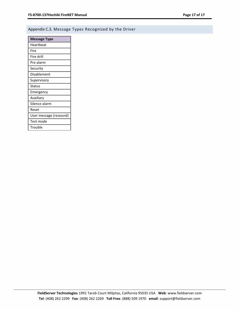
Appendix C.3. Message Types Recognized by the Driver
Message Type
Heartbeat
Fire
Fire drill
Pre alarm
Security
Disablement
Supervisory
Status
Emergency
Auxiliary
Silence alarm
Reset
User message (resound)
Test mode
Trouble