driver specifications: oriental motor 5-phase stepping
TRANSCRIPT
-4511 -4521
Driver Specifications: Oriental Motor 5-phase Stepping Motor Driver Specifications / Cable Cable
Recommended for use with LX Single Axis Actuator with motor. A 3m long cable is included as the standard accessory; if different cable length is required, order the cable separately.Other than those listed on this page, FA Electronics Catalog lists more various items with shield or custom alterations. For details, please see Wiring Components Catalog. Please check with the latest Wiring Components Catalog or MISUMI eCatalog.
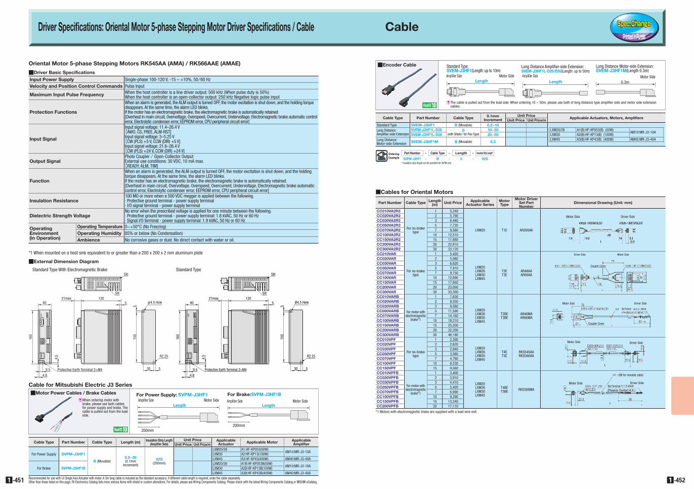
QEncoder Cable
QCables for Oriental Motors
Cable Type Part Number Cable Type 0.1mm Increment
Unit PriceApplicable Actuators, Motors, Amplifiers
Unit Price Unit Price/mStandard Type SVEM-J3HF1 B (Movable) 0.2~10Long Distance Amplifier-side Extension
SVEM-J3HF1L-D20 D(with Shield / for Flex Type)
10~20 LXM20/26 A1(B):HF-KP053(B) (50W)AM10:MR-J3-10A
SVEM-J3HF1L-D50 20~50 LXM30 A2(B):HF-KP13(B) (100W)Long Distance Motor-side Extension SVEM-J3HF1M B (Movable) 0.3
LXM45 A3(B):HF-KP43(B) (400W) AM40:MR-J3-40A
Oriental Motor 5-phase Stepping Motors RK545AA (AMA) / RK566AAE (AMAE)
QDriver Basic SpecificationsInput Power Supply Single-phase 100-120 V, -15 – +10%, 50/60 HzVelocity and Position Control Commands Pulse Input
Maximum Input Pulse Frequency When the host controller is a line driver output: 500 kHz (When pulse duty is 50%)When the host controller is an open-collector output: 250 kHz Negative logic pulse input
Protection Functions
When an alarm is generated, the ALM output is turned OFF, the motor excitation is shut down, and the holding torque disappears. At the same time, the alarm LED blinks.If the motor has an electromagnetic brake, the electromagnetic brake is automatically retained.[Overheat in main circuit, Overvoltage, Overspeed, Overcurrent, Undervoltage, Electromagnetic brake automatic control error, Electrolytic condenser error, EEPROM error, CPU peripheral circuit error]
Input Signal
Input signal voltage: 11.4–26.4 V[AWO, CS, FREE, ALM-RST]
Input signal voltage: 3–5.25 V[CW (PLS) +5 V, CCW (DIR) +5 V]
Input signal voltage: 21.6–26.4 V[CW (PLS) +24 V, CCW (DIR) +24 V]
Output SignalPhoto Coupler / Open-Collector Output External use conditions: 30 VDC, 10 mA max.[READY, ALM, TIM]
Function
When an alarm is generated, the ALM output is turned OFF, the motor excitation is shut down, and the holding torque disappears. At the same time, the alarm LED blinks.If the motor has an electromagnetic brake, the electromagnetic brake is automatically retained.[Overheat in main circuit, Overvoltage, Overspeed, Overcurrent, Undervoltage, Electromagnetic brake automatic control error, Electrolytic condenser error, EEPROM error, CPU peripheral circuit error]
Insulation Resistance100 MΩ or more when a 500 VDC megger is applied between the following.· Protective ground terminal - power supply terminal· I/O signal terminal - power supply terminal
Dielectric Strength VoltageNo error when the prescribed voltage is applied for one minute between the following.· Protective ground terminal - power supply terminal: 1.8 kVAC, 50 Hz or 60 Hz· Signal I/O terminal - power supply terminal: 1.9 kVAC, 50 Hz or 60 Hz
Operating Environment (in Operation)
Operating Temperature 0~+50°C (No Freezing)Operating Humidity 85% or below (No Condensation)Ambience No corrosive gases or dust. No direct contact with water or oil.
*1 When mounted on a heat sink equivalent to or greater than a 200 x 200 x 2 mm aluminum plate
QExternal Dimension Diagram
Standard Type With Electromagnetic Brake Standard Type
4021max. 120
5
160
4.8
9.5
4.5
Protective Earth Terminal 2×M4
515
0
30 5
Slit
Slit
Ø4.5 Hole
R2.25
4021max. 120
5
160
4.8
9.5
4.5
Protective Earth Terminal 2×M4
515
0
30 5
Slit
Slit
φ4.5 Hole
R2.25
Part Number Cable Type Length (m) Unit Price Applicable
Actuator SeriesMotor Type
Motor Driver Set Part Number
Dimensional Drawing (Unit: mm)
CC010VA2R2
For no-brake type
1 5,240
LXM20 T1E AR26SAK
Motor Side Driver SideCC020VA2R2 2 5,790CC030VA2R2 3 6,440CC050VA2R2 5 7,720CC070VA2R2 7 9,560CC100VA2R2 10 12,510CC150VA2R2 15 17,660CC200VA2R2 20 22,810CC300VA2R2 30 33,120CC010VAR
For no-brake type
1 5,420
LXM20LXM26LXM30LXM45
T2ET3E
AR46AAAR66AA
Motor SideDriver Side
Coupler Cover
CC020VAR 2 5,980CC030VAR 3 6,620CC050VAR 5 7,910CC070VAR 7 9,750CC100VAR 10 12,690CC150VAR 15 17,840CC200VAR 20 23,000CC300VAR 30 33,300CC010VARB
For motor with electromagnetic
brake*1
1 7,630
LXM20LXM26LXM30LXM45
T2BET3BE
AR46MAAR66MA
Motor Side
Rod Terminal
Coupler Cover
Driver SideCC020VARB 2 8,550CC030VARB 3 9,560CC050VARB 5 11,590CC070VARB 7 14,160CC100VARB 10 18,210CC150VARB 15 25,200CC200VARB 20 32,200CC300VARB 30 46,180CC010VPF
For no-brake type
1 2,300
LXM20LXM26LXM30LXM45
T4ET5E
RKS545AARKS566AA
Motor Side Driver SideCC020VPF 2 2,620CC030VPF 3 2,940CC050VPF 5 3,580CC070VPF 7 4,780CC100VPF 10 6,530CC150VPF 15 9,560CC010VPFB
For motor with electromagnetic
brake*1
1 3,400
LXM20LXM26LXM30LXM45
T4BET5BE RKS566MA
Motor Side Driver SideRod Terminal(Phoenix Contact K.K.)
(Ø6 for movable cable)CC020VPFB 2 3,910CC030VPFB 3 4,410CC050VPFB 5 5,420CC070VPFB 7 6,990CC100VPFB 10 9,290CC150VPFB 15 13,240CC200VPFB 20 17,110
*1 Motors with electromagnetic brake are supplied with a lead wire exit.
QMotor Power Cables / Brake Cables
Cable for Mitsubishi Electric J3 Series
E When ordering motor with brake, please use both cables for power supply and brake. The cable is pulled out from the load side.
Cable Type Part Number Cable Type Length (m) Insulation Strip Length (Amplifier Side)
Unit Price Applicable Actuator Applicable Motor Applicable
AmplifierUnit Price Unit Price/m
For Power Supply SVPM-J3HF1
B (Movable)0.2~30(0.1mm
Increment)
02S(200mm)
LXM20/26 A1:HF-KP053(50W)AM10:MR-J3-10A
LXM30 A2:HF-KP13(100W)LXM45 A3:HF-KP43(400W) AM40:MR-J3-40A
For Brake SVPM-J3HF1BLXM20/26 A1B:HF-KP053B(50W)
AM10:MR-J3-10ALXM30 A2B:HF-KP13B(100W)LXM45 A3B:HF-KP43B(400W) AM40:MR-J3-40A
200mm
LengthMotor SideAmplifier Side
For Brake:SVPM-J3HF1B
200mm
LengthMotor SideAmplifier Side
For Power Supply: SVPM-J3HF1
E The cable is pulled out from the load side. When ordering 10 ~ 50m, please use both of long distance type amplifier side and motor side extension cables.
LengthMotor SideAmplifier Side
Standard Type:SVEM-J3HF1(Length: up to 10m)
LengthAmplifier Side
Long Distance Amplifier-side Extension:SVEM-J3HF1L-D20/D50(Length: up to 50m)
Motor Side0.3m
Long Distance Motor-side Extension:SVEM-J3HF1M(Length 0.3m)
Part Number - Cable Type - Length - Insulation Strip Length*
SVPM-J3HF1 - B - 5 - 02S* Insulation strip length can be specified for SVPM only.