drm130: watt saver for a cell phone ac adapter -...
TRANSCRIPT
Watt Saver for a Cell Phone ACAdapter
Reference Design
Document Number: DRM130Rev 1, 10/2013

Watt Saver for a Cell Phone AC Adapter, Rev. 1, 10/2013
2 Freescale Semiconductor, Inc.

Contents
Section number Title Page
Chapter 1Introduction
1.1 Overview...........................................................................................................................................................................5
1.2 Freescale solution..............................................................................................................................................................5
1.3 Demo board features.........................................................................................................................................................7
Chapter 2Hardware Description
2.1 Demo board application block diagram............................................................................................................................9
2.2 Modules explanation.........................................................................................................................................................9
2.3 Demo board content..........................................................................................................................................................10
2.4 Relay type and connections..............................................................................................................................................12
2.5 Super capacitor low voltage detection circuit...................................................................................................................13
2.6 Device detection circuit....................................................................................................................................................14
2.7 Current measurement circuit.............................................................................................................................................14
Chapter 3Firmware Description
3.1 Demo board operation modes...........................................................................................................................................17
3.2 State diagram....................................................................................................................................................................17
3.3 Relay software control......................................................................................................................................................18
3.4 Super capacitor voltage measurement algorithm..............................................................................................................19
3.5 Super capacitor low voltage detection method.................................................................................................................20
3.6 Device detection and current measurement algorithm......................................................................................................21
Chapter 4Performance Results
4.1 Operating parameters........................................................................................................................................................23
4.2 Average power consumption ...........................................................................................................................................23
Watt Saver for a Cell Phone AC Adapter, Rev. 1, 10/2013
Freescale Semiconductor, Inc. 3

Watt Saver for a Cell Phone AC Adapter, Rev. 1, 10/2013
4 Freescale Semiconductor, Inc.

Chapter 1Introduction
1.1 OverviewInnovative Watt Saver no-load technology for AC adapters prevents wasting power whenno device is connected.
Freescale Semiconductor is finding innovative ways to stop “vampire” energy loss, thatis, is the loss of power that occurs when an AC adapter is plugged into an electrical outletbut isn’t charging a device.
Freescale’s new Watt Saver technology automatically eliminates no-load powerconsumption for AC adapters, potentially providing substantial energy savings overexisting manual versions. Freescale’s Watt Saver technology consists of patent-pendinghardware and software implementations enabling the main power source to bedisconnected when no power is required by the connected device.
1.2 Freescale solutionThe Watt Saver reference design is an example of how a “Smart Switch” can be builttaking advantage of the MC9RS08KA4 features. The main features of thismicrocontroller that make it ideal for Watt Saver solution are:
• Low cost implementation• Power saving modes• 12-channel 10-bit resolution analog-to-digital converter (ADC)• Analog Comparator (ACMP)• Real-Time Interrupt (RTI)• Up to 18 GPIOs including one output-only and one input-only pin• Background debugging system on-chip• Wake from stop mode based on analog comparator module, real time interrupt and
key board interrupt events
The Watt Saver charger block diagram is shown in Figure 1-1.
Watt Saver for a Cell Phone AC Adapter, Rev. 1, 10/2013
Freescale Semiconductor, Inc. 5
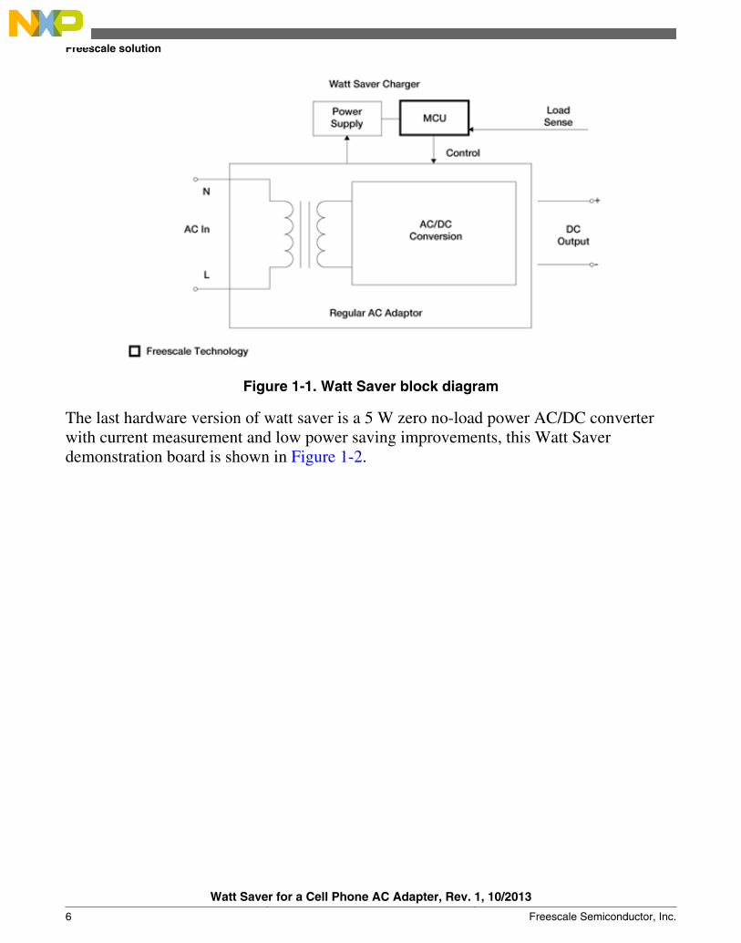
Figure 1-1. Watt Saver block diagram
The last hardware version of watt saver is a 5 W zero no-load power AC/DC converterwith current measurement and low power saving improvements, this Watt Saverdemonstration board is shown in Figure 1-2.
Freescale solution
Watt Saver for a Cell Phone AC Adapter, Rev. 1, 10/2013
6 Freescale Semiconductor, Inc.

Figure 1-2. Watt Saver demonstration board
1.3 Demo board featuresThe Watt Saver demonstration board includes the following features:
• Support for 110 V and 220 V• Discrete H-Bridge• 1 F – 5.5 V super cap• Support common and ground (GND)-shield USB cables• Device end-of-charge detection (cell phone, mp3 player)
Chapter 1 Introduction
Watt Saver for a Cell Phone AC Adapter, Rev. 1, 10/2013
Freescale Semiconductor, Inc. 7
NOTEA GND-shield cable is a cable with GND and shield tiedtogether on the cable.
Demo board features
Watt Saver for a Cell Phone AC Adapter, Rev. 1, 10/2013
8 Freescale Semiconductor, Inc.

Chapter 2Hardware Description
2.1 Demo board application block diagramThe design block diagram is found on Figure 2-1.
Figure 2-1. Design block diagram
2.2 Modules explanationMicrocontroller (MCU)
Watt Saver for a Cell Phone AC Adapter, Rev. 1, 10/2013
Freescale Semiconductor, Inc. 9
The RS08KA4 microcontroller is used to control all operational modes, current, voltagemeasurements, and GND-shield detection.
The following are the MCU modules used in this application:• Analog comparator (ACMP)• Keyboard Interrupt (KBI)• Real-Time Interrupt (RTI)• 10-bit Analog to Digital Converter (ADC)
Discrete AC/DC Converter
This module has the following characteristics.• Input — 110–220 V• Output — 5 V / 1 A
Super Capacitor (super cap.)
Super cap is the power supply for Watt Saver when it is in low-power mode. It is usedinstead of a battery. This is a 1 Farad, 5.5 Volts super cap.
H–Bridge
Discrete H-bridge is created with two complementary pair enhancement mode field-effecttransistors, H-bridge is used to generate the control signal needed to switch relay betweenAC mode and low power mode.
Relay
A bistable coil type relay is used to disconnect the AC power line from the rest of thecircuit when the Watt Saver is in low-power mode. This component has the followingcharacteristics:
• Bistable coil type• 110/220 VAC compatible• 2.4 VDC rated voltage
2.3 Demo board contentThe Watt Saver demo board contains several blocks needed for the implementation of ano-load AC charger. The main blocks and components of this demo board are highlightedIn Figure 2-2 and Figure 2-3.
Demo board content
Watt Saver for a Cell Phone AC Adapter, Rev. 1, 10/2013
10 Freescale Semiconductor, Inc.
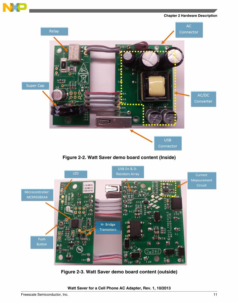
Figure 2-2. Watt Saver demo board content (Inside)
Figure 2-3. Watt Saver demo board content (outside)
Chapter 2 Hardware Description
Watt Saver for a Cell Phone AC Adapter, Rev. 1, 10/2013
Freescale Semiconductor, Inc. 11
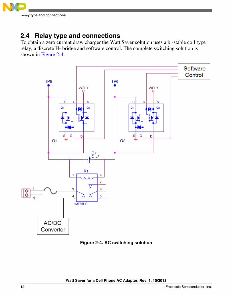
2.4 Relay type and connectionsTo obtain a zero current draw charger the Watt Saver solution uses a bi-stable coil typerelay, a discrete H- bridge and software control. The complete switching solution isshown in Figure 2-4.
Figure 2-4. AC switching solution
Relay type and connections
Watt Saver for a Cell Phone AC Adapter, Rev. 1, 10/2013
12 Freescale Semiconductor, Inc.
A bi-stable relay is used because the application needs to improve the consumption inlow power mode. The main feature of this relay is that it requires a current pulse withpolarity to switch between both states. While the coil is relaxed the contacts remain in itsprevious position and no energy is being consumed. When the current pulse is providedthe coil consumes power only for an instant.
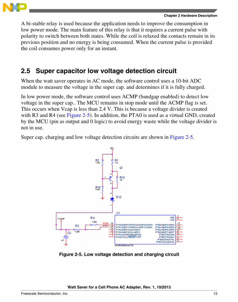
2.5 Super capacitor low voltage detection circuitWhen the watt saver operates in AC mode, the software control uses a 10-bit ADCmodule to measure the voltage in the super cap. and determines if it is fully charged.
In low power mode, the software control uses ACMP (bandgap enabled) to detect lowvoltage in the super cap.. The MCU remains in stop mode until the ACMP flag is set.This occurs when Vcap is less than 2.4 V. This is because a voltage divider is createdwith R3 and R4 (see Figure 2-5). In addition, the PTA0 is used as a virtual GND, createdby the MCU (pin as output and 0 logic) to avoid energy waste while the voltage divider isnot in use.
Super cap. charging and low voltage detection circuits are shown in Figure 2-5.
Figure 2-5. Low voltage detection and charging circuit
Chapter 2 Hardware Description
Watt Saver for a Cell Phone AC Adapter, Rev. 1, 10/2013
Freescale Semiconductor, Inc. 13

2.6 Device detection circuitMost cell phones have the ability to tie together GND and Shield signals when a USBcable is connected. The Watt Saver takes advantage of this behavior using a pull-upresistor circuit and a GPIO to detect when a device is connected. This circuit is shown inFigure 2-6.
When no device is connected the MCU reads a logic “1” in the GPIO pin. If a cell phoneis connected, the shield signal is tied to GND. When the MCU detects a falling edge itwakes the Watt Saver and enters in AC mode.
Figure 2-6. Device detection circuit
2.7 Current measurement circuitOne of the most relevant features is the device end-of-charge detection and the ability tosupport ground-shield cables. The Watt Saver detects a device based on the union ofGND and shield, this occurs when the device is connected to the cable, although currentlysome cables have this union without any device connected.
This feature is implemented using a 10-bit ADC and the current measurement circuit.This circuit includes the amplifier MAX4372 ( x100 gain), which increases themeasurement resolution. The Watt Saver detects when a cable is connected to the USBconnector. The current is measured to determine if there is any connected device. Thehighest and the lowest current values can be selected via software, this indicates that theWatt Saver can be customized for specific or generic devices. The current measurementcircuit is shown in Figure 2-7.
The operational ranges are:
Device detection circuit
Watt Saver for a Cell Phone AC Adapter, Rev. 1, 10/2013
14 Freescale Semiconductor, Inc.
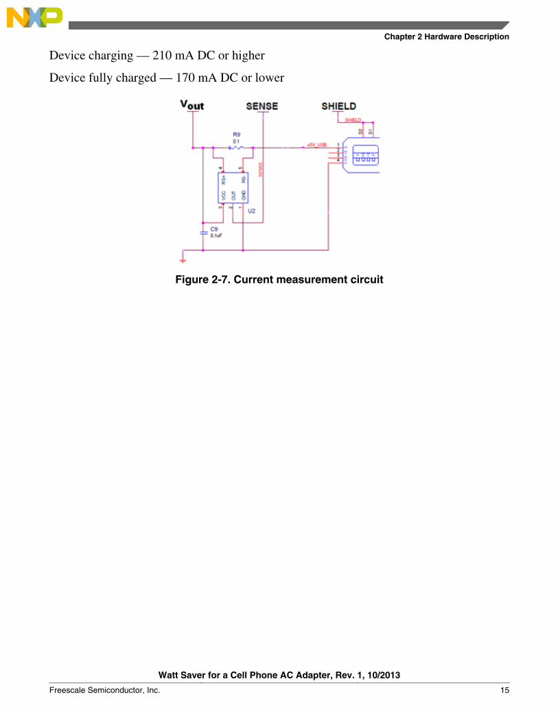
Device charging — 210 mA DC or higher
Device fully charged — 170 mA DC or lower
Figure 2-7. Current measurement circuit
Chapter 2 Hardware Description
Watt Saver for a Cell Phone AC Adapter, Rev. 1, 10/2013
Freescale Semiconductor, Inc. 15

Current measurement circuit
Watt Saver for a Cell Phone AC Adapter, Rev. 1, 10/2013
16 Freescale Semiconductor, Inc.
Chapter 3Firmware Description
3.1 Demo board operation modesThe Watt Saver has three operational modes:
• AC mode—The Watt Saver remains in this operational mode when a device isconnected and charging or when the super cap is not fully charged. The LED remainsturned on.
• Low Power mode (super cap. mode)—The Watt Saver switches to this operationalmode when a device is not connected and super cap. is fully charged. Any device orGND-shield cable connection wakes the watt saver and switches to AC mode. TheLED remains turned off.
• Wait Cable mode—The Watt Saver switches to this operational mode when the supercap. is fully charged and one of the following conditions happens:
• The device is connected and the device battery is fully charged.• Only the GND–shield cable is connected and the device is not.
If device or GND-shield cable is disconnected, then the Watt Saver switches to super cap.mode.
If the Watt Saver detects a low voltage in the super cap., it then switches to AC mode.
The Watt Saver returns to AC mode periodically to detect the device currentmeasurement and to charge the device again, if needed. The LED turns on periodicallyevery 20 minutes. This time can be configured with the watt saver component propertyWAIT_TIME.
3.2 State diagramThe state diagram is found on Figure 3-1.
Watt Saver for a Cell Phone AC Adapter, Rev. 1, 10/2013
Freescale Semiconductor, Inc. 17
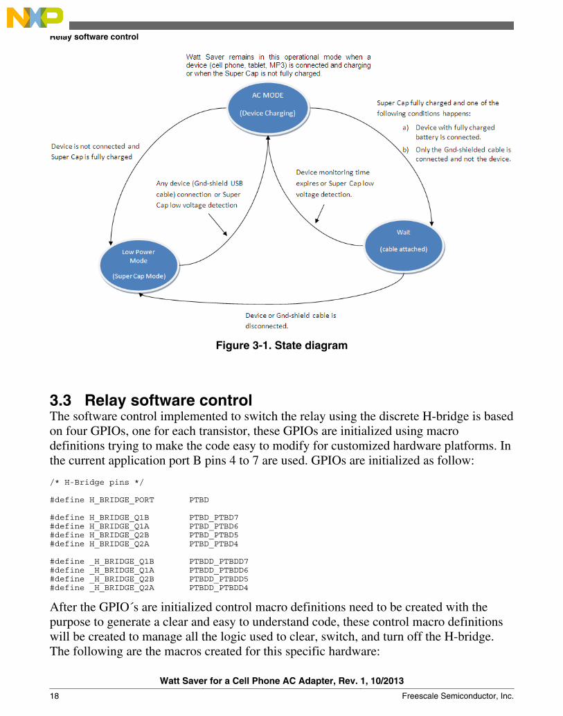
Figure 3-1. State diagram
3.3 Relay software controlThe software control implemented to switch the relay using the discrete H-bridge is basedon four GPIOs, one for each transistor, these GPIOs are initialized using macrodefinitions trying to make the code easy to modify for customized hardware platforms. Inthe current application port B pins 4 to 7 are used. GPIOs are initialized as follow:
/* H-Bridge pins */
#define H_BRIDGE_PORT PTBD
#define H_BRIDGE_Q1B PTBD_PTBD7 #define H_BRIDGE_Q1A PTBD_PTBD6#define H_BRIDGE_Q2B PTBD_PTBD5#define H_BRIDGE_Q2A PTBD_PTBD4
#define _H_BRIDGE_Q1B PTBDD_PTBDD7 #define _H_BRIDGE_Q1A PTBDD_PTBDD6#define _H_BRIDGE_Q2B PTBDD_PTBDD5#define _H_BRIDGE_Q2A PTBDD_PTBDD4
After the GPIO´s are initialized control macro definitions need to be created with thepurpose to generate a clear and easy to understand code, these control macro definitionswill be created to manage all the logic used to clear, switch, and turn off the H-bridge.The following are the macros created for this specific hardware:
Relay software control
Watt Saver for a Cell Phone AC Adapter, Rev. 1, 10/2013
18 Freescale Semiconductor, Inc.
#define H_BRIDGE_CLEAR 0x0F#define H_BRIDGE_OFF 0xA0#define H_BRIDGE_AC 0x30#define H_BRIDGE_VCAP 0xC0
With the macro definitions created the switching of the relay can be implemented in threelines, in the following piece of code the first group of instructions are used to switch therelay to AC mode, and the second group is used to switch to low power mode.
gu8PTB_temp = H_BRIDGE_PORT; // Store PTBD value in temp variablegu8PTB_temp = (gu8PTB_temp & H_BRIDGE_CLEAR); // Clear H-Bridge Bits (7-4)H_BRIDGE_PORT = (gu8PTB_temp | H_BRIDGE_AC); // Change to AC Mode
gu8PTB_temp = H_BRIDGE_PORT; // Store PTBD value in temp variablegu8PTB_temp = (gu8PTB_temp & H_BRIDGE_CLEAR); // Clear H-Bridge Bits (7-4)H_BRIDGE_PORT = (gu8PTB_temp | H_BRIDGE_VCAP); // Change to Vcap Mode
3.4 Super capacitor voltage measurement algorithmThe Watt Saver hardware used to detect when the super cap. is fully charged is an ADCpin in combination with a voltage divider circuit. A GPIO is used to enable or disable thevoltage divider and avoid energy waste. Following are the macro definitions created forthis purpose.
#define SUPCAP_MEASUREMENT_CTRL PTAD_PTAD0#define _SUPCAP_MEASUREMENT_CTRL PTADD_PTADD0#define CAP_ADC 1 /*Super Cap ADC #1*/
To enable the voltage divider and perform a voltage measurement the GPIO needs to beset as an Output with a logic value of 0, this will create a virtual ground to close thecircuit. The instructions are shown below.
SUPCAP_MEASUREMENT_CTRL = 0; // Set por as 0 _SUPCAP_MEASUREMENT_CTRL = _OUT; // Set port as ouput for measure Vcap
The output of the voltage divider circuit is Vin/2. In the Watt Saver application, a macrodefinition with the desired value at which the application detects that the super cap. isfully charged needs to be created. In the watt saver application 4.7 volts is the desiredlimit for the super cap. because it uses a 1 F, 5.5 V super cap. The charging circuit isdesigned to charge up to 5 volts.
#define V_MAX 512 /*4.7 Volts*/#define V_HIS 500 /*Histeresis(10 Units)*/
The ADC counts assigned to the macro V_MAX are obtained as follows:
ADC resolution is 10-bit, so the highest value is 1024. The voltage that is powering theMCU is 4.7 volts so, (1024 * ((4.7)V / (2))) / 4.7 V = 512 ADC counts.
After the macro definitions are created, the ADC module needs to be initialized asfollow:
Chapter 3 Firmware Description
Watt Saver for a Cell Phone AC Adapter, Rev. 1, 10/2013
Freescale Semiconductor, Inc. 19
ADCCFG= ADCCFG_MODE1_MASK; // 10 bit conversionAPCTL1_ADPC1=1; // Enable ADC1(PTA1) for super cap. voltage measurement
To improve the accuracy of the voltage measurement, an algorithm to obtain the medianvalue was developed, the first eight samples are stored in an array then the followingsegment code is implemented.
do { u8CompletFlag=0; for (gu8Counter=0;gu8Counter<7;gu8Counter++) { if (gu16TempArray[gu8Counter] > gu16TempArray[gu8Counter+1]) { gu16TempValue = gu16TempArray[gu8Counter]; gu16TempArray[gu8Counter] = gu16TempArray[gu8Counter+1]; gu16TempArray[gu8Counter+1] = gu16TempValue; u8CompletFlag=1; } } }while (u8CompletFlag) gu16ADCVoltage_avg = ((gu16TempArray[3] + gu16TempArray[4])/2); // ADC median equation
After this, compare the V_MAX macro definition value with this ADC median result anddecide if the super cap. is fully charged or not.
3.5 Super capacitor low voltage detection methodThe ACMP module in combination with a voltage divider circuit used to detect when thesuper cap. is working at a low voltage range. As mentioned in the previous section thevoltage divider needs to be enabled to obtain an accurate comparison.
The ACMP compares the voltage divider output with the Bandgap reference (1.2 V),therefore the bandgap reference must be enabled and the ACMP must be initialized.
SPMSC1=SPMSC1_BGBE_MASK;ACMPSC= ACMPSC_ACME_MASK |ACMPSC_ACBGS_MASK | ACMPSC_ACMOD0_MASK;
In the previous configuration, select the bandgap reference as one of the signals tocompare and set the ACMP output as rising edge. This generates the ACMPSC_ACOflag set when the super cap. voltage is lower than the bandgap reference.
The ACMP module is enabled in the super cap. mode function, each desired time toperform a comparison and decide if the super cap. is working in low voltage range. Theapplication needs to operate with low power consumption. A device connection or anaccidental switching of the relay events are implemented in the algorithm for super cap.mode, if one of these conditions occurs then the Watt Saver switches to AC mode.
Super capacitor low voltage detection method
Watt Saver for a Cell Phone AC Adapter, Rev. 1, 10/2013
20 Freescale Semiconductor, Inc.
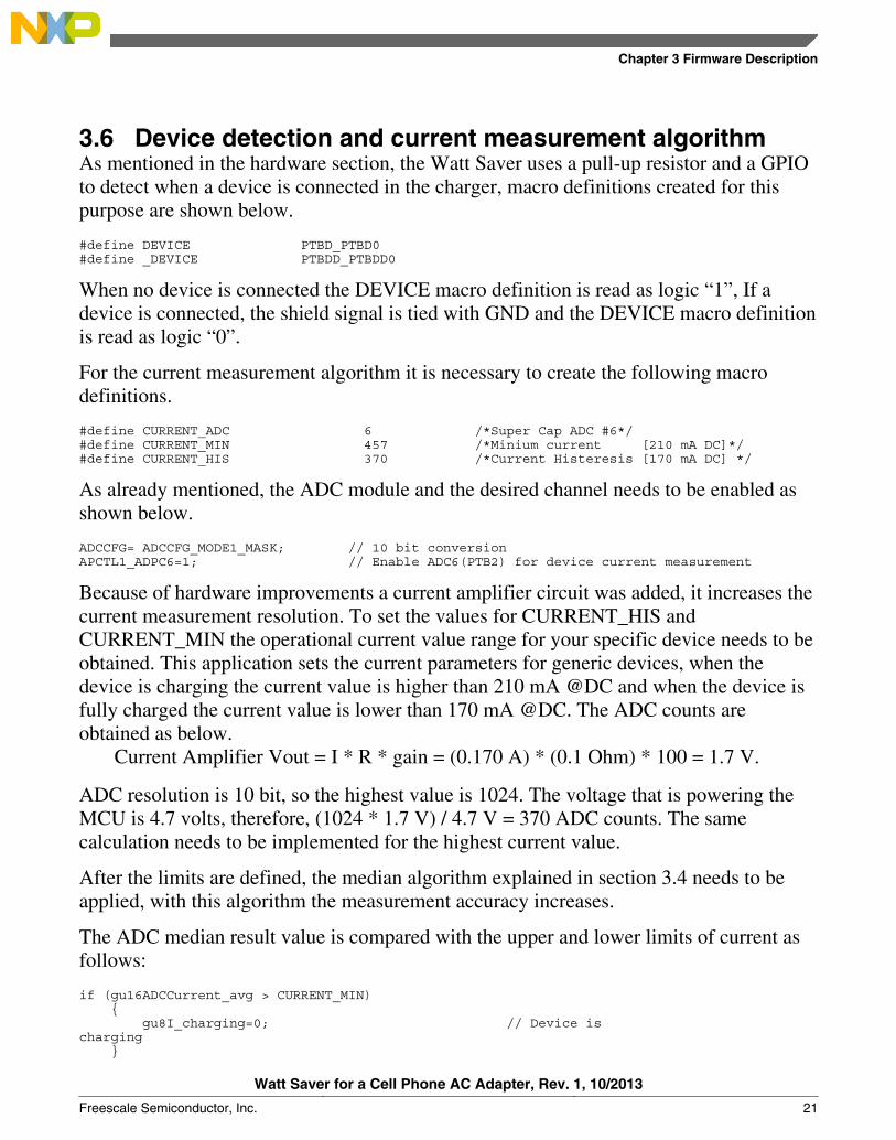
3.6 Device detection and current measurement algorithmAs mentioned in the hardware section, the Watt Saver uses a pull-up resistor and a GPIOto detect when a device is connected in the charger, macro definitions created for thispurpose are shown below.
#define DEVICE PTBD_PTBD0#define _DEVICE PTBDD_PTBDD0
When no device is connected the DEVICE macro definition is read as logic “1”, If adevice is connected, the shield signal is tied with GND and the DEVICE macro definitionis read as logic “0”.
For the current measurement algorithm it is necessary to create the following macrodefinitions.
#define CURRENT_ADC 6 /*Super Cap ADC #6*/#define CURRENT_MIN 457 /*Minium current [210 mA DC]*/#define CURRENT_HIS 370 /*Current Histeresis [170 mA DC] */
As already mentioned, the ADC module and the desired channel needs to be enabled asshown below.
ADCCFG= ADCCFG_MODE1_MASK; // 10 bit conversionAPCTL1_ADPC6=1; // Enable ADC6(PTB2) for device current measurement
Because of hardware improvements a current amplifier circuit was added, it increases thecurrent measurement resolution. To set the values for CURRENT_HIS andCURRENT_MIN the operational current value range for your specific device needs to beobtained. This application sets the current parameters for generic devices, when thedevice is charging the current value is higher than 210 mA @DC and when the device isfully charged the current value is lower than 170 mA @DC. The ADC counts areobtained as below.
Current Amplifier Vout = I * R * gain = (0.170 A) * (0.1 Ohm) * 100 = 1.7 V.
ADC resolution is 10 bit, so the highest value is 1024. The voltage that is powering theMCU is 4.7 volts, therefore, (1024 * 1.7 V) / 4.7 V = 370 ADC counts. The samecalculation needs to be implemented for the highest current value.
After the limits are defined, the median algorithm explained in section 3.4 needs to beapplied, with this algorithm the measurement accuracy increases.
The ADC median result value is compared with the upper and lower limits of current asfollows:
if (gu16ADCCurrent_avg > CURRENT_MIN) { gu8I_charging=0; // Device is charging }
Chapter 3 Firmware Description
Watt Saver for a Cell Phone AC Adapter, Rev. 1, 10/2013
Freescale Semiconductor, Inc. 21
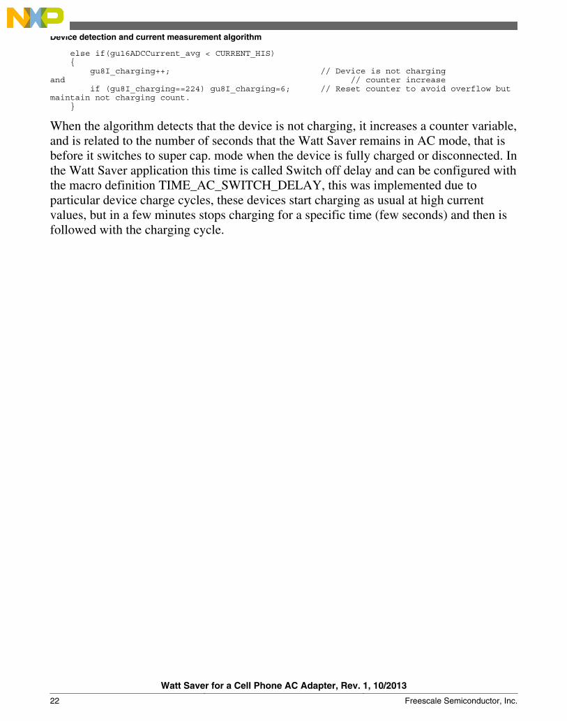
else if(gu16ADCCurrent_avg < CURRENT_HIS) { gu8I_charging++; // Device is not charging and // counter increase if (gu8I_charging==224) gu8I_charging=6; // Reset counter to avoid overflow but maintain not charging count. }
When the algorithm detects that the device is not charging, it increases a counter variable,and is related to the number of seconds that the Watt Saver remains in AC mode, that isbefore it switches to super cap. mode when the device is fully charged or disconnected. Inthe Watt Saver application this time is called Switch off delay and can be configured withthe macro definition TIME_AC_SWITCH_DELAY, this was implemented due toparticular device charge cycles, these devices start charging as usual at high currentvalues, but in a few minutes stops charging for a specific time (few seconds) and then isfollowed with the charging cycle.
Device detection and current measurement algorithm
Watt Saver for a Cell Phone AC Adapter, Rev. 1, 10/2013
22 Freescale Semiconductor, Inc.
Chapter 4Performance Results
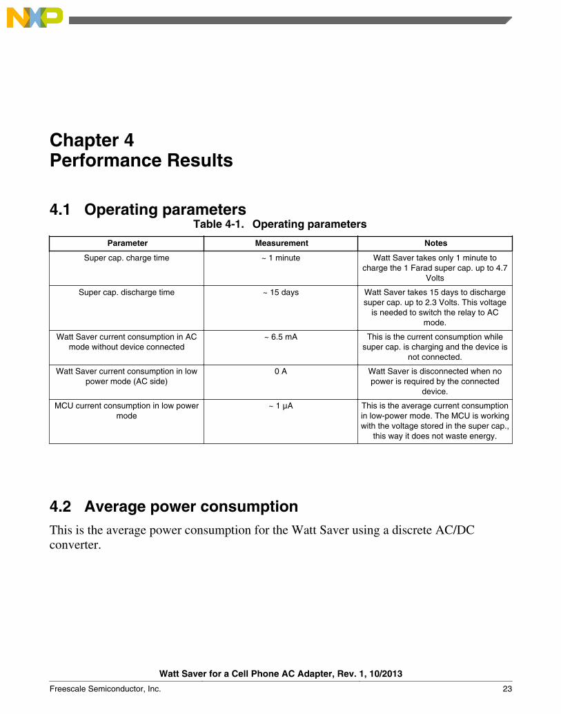
4.1 Operating parametersTable 4-1. Operating parameters
Parameter Measurement Notes
Super cap. charge time ~ 1 minute Watt Saver takes only 1 minute tocharge the 1 Farad super cap. up to 4.7
Volts
Super cap. discharge time ~ 15 days Watt Saver takes 15 days to dischargesuper cap. up to 2.3 Volts. This voltage
is needed to switch the relay to ACmode.
Watt Saver current consumption in ACmode without device connected
~ 6.5 mA This is the current consumption whilesuper cap. is charging and the device is
not connected.
Watt Saver current consumption in lowpower mode (AC side)
0 A Watt Saver is disconnected when nopower is required by the connected
device.
MCU current consumption in low powermode
~ 1 µA This is the average current consumptionin low-power mode. The MCU is workingwith the voltage stored in the super cap.,
this way it does not waste energy.
4.2 Average power consumptionThis is the average power consumption for the Watt Saver using a discrete AC/DCconverter.
Watt Saver for a Cell Phone AC Adapter, Rev. 1, 10/2013
Freescale Semiconductor, Inc. 23
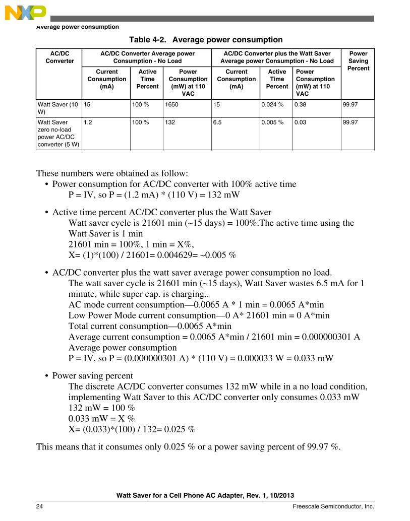
Table 4-2. Average power consumption
AC/DCConverter
AC/DC Converter Average powerConsumption - No Load
AC/DC Converter plus the Watt SaverAverage power Consumption - No Load
PowerSavingPercentCurrent
Consumption(mA)
ActiveTime
Percent
PowerConsumption(mW) at 110
VAC
CurrentConsumption
(mA)
ActiveTime
Percent
PowerConsumption(mW) at 110VAC
Watt Saver (10W)
15 100 % 1650 15 0.024 % 0.38 99.97
Watt Saverzero no-loadpower AC/DCconverter (5 W)
1.2 100 % 132 6.5 0.005 % 0.03 99.97
These numbers were obtained as follow:• Power consumption for AC/DC converter with 100% active time
P = IV, so P = (1.2 mA) * (110 V) = 132 mW
• Active time percent AC/DC converter plus the Watt SaverWatt saver cycle is 21601 min (~15 days) = 100%.The active time using theWatt Saver is 1 min21601 min = 100%, 1 min = X%,X= (1)*(100) / 21601= 0.004629= ~0.005 %
• AC/DC converter plus the watt saver average power consumption no load.The watt saver cycle is 21601 min (~15 days), Watt Saver wastes 6.5 mA for 1minute, while super cap. is charging..AC mode current consumption—0.0065 A * 1 min = 0.0065 A*minLow Power Mode current consumption—0 A* 21601 min = 0 A*minTotal current consumption—0.0065 A*minAverage current consumption = 0.0065 A*min / 21601 min = 0.000000301 AAverage power consumptionP = IV, so P = (0.000000301 A) * (110 V) = 0.000033 W = 0.033 mW
• Power saving percentThe discrete AC/DC converter consumes 132 mW while in a no load condition,implementing Watt Saver to this AC/DC converter only consumes 0.033 mW132 mW = 100 %0.033 mW = X %X= (0.033)*(100) / 132= 0.025 %
This means that it consumes only 0.025 % or a power saving percent of 99.97 %.
Average power consumption
Watt Saver for a Cell Phone AC Adapter, Rev. 1, 10/2013
24 Freescale Semiconductor, Inc.
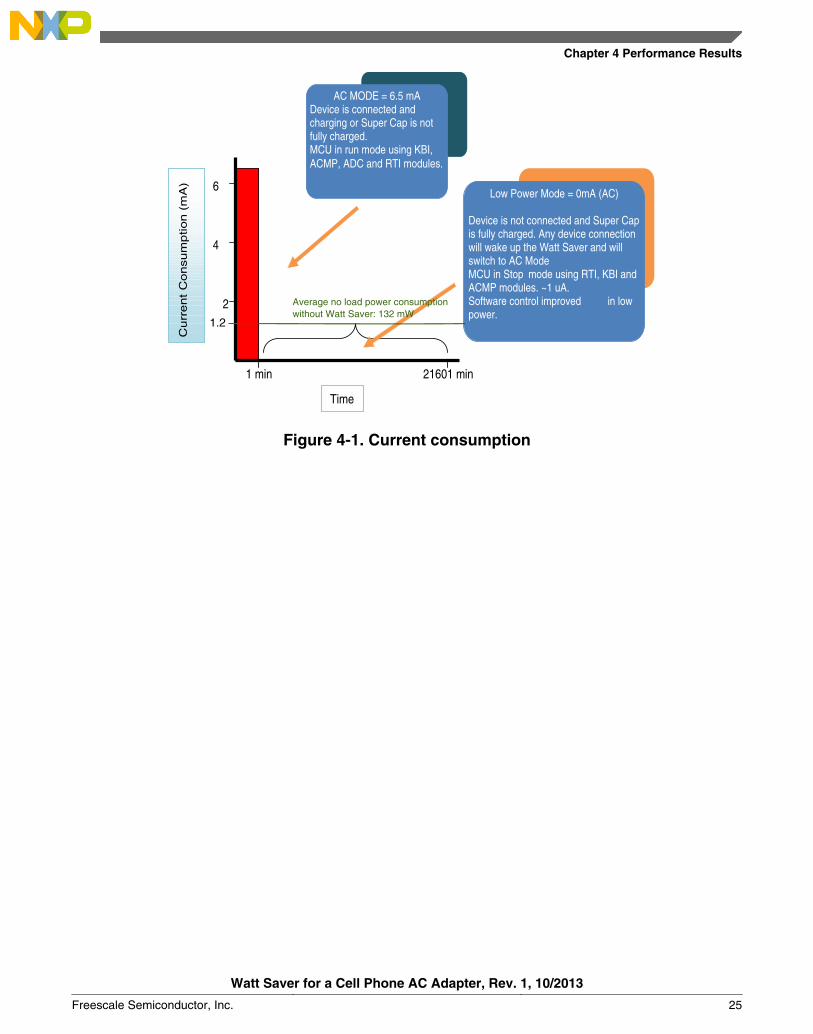
Time
Curr
ent
Consum
ption (
mA
)
1 min 21601 min
2
4
6
AC MODE = 6.5 mA Device is connected and charging or Super Cap is not fully charged. MCU in run mode using KBI, ACMP, ADC and RTI modules.
Low Power Mode = 0mA (AC) Device is not connected and Super Cap is fully charged. Any device connection will wake up the Watt Saver and will switch to AC Mode MCU in Stop mode using RTI, KBI and ACMP modules. ~1 uA. Software control improved in low power.
Average no load power consumptionwithout Watt Saver: 132 mW
1.2
Figure 4-1. Current consumption
Chapter 4 Performance Results
Watt Saver for a Cell Phone AC Adapter, Rev. 1, 10/2013
Freescale Semiconductor, Inc. 25

Average power consumption
Watt Saver for a Cell Phone AC Adapter, Rev. 1, 10/2013
26 Freescale Semiconductor, Inc.
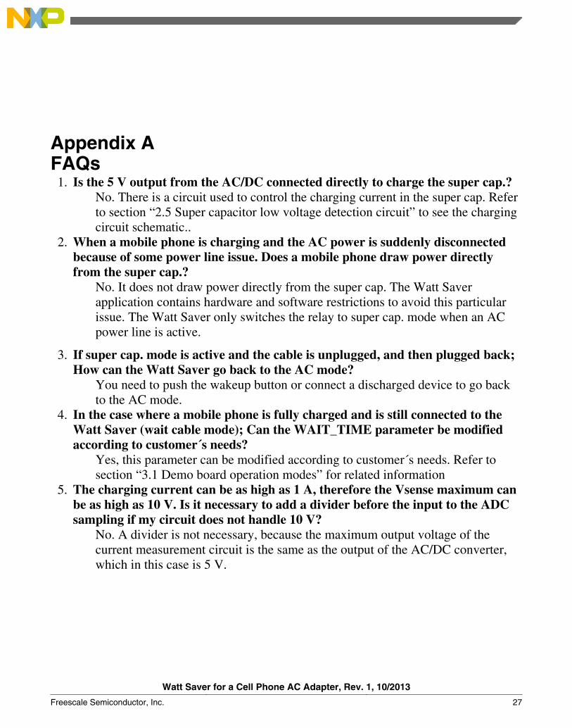
Appendix AFAQs
1. Is the 5 V output from the AC/DC connected directly to charge the super cap.?No. There is a circuit used to control the charging current in the super cap. Referto section “2.5 Super capacitor low voltage detection circuit” to see the chargingcircuit schematic..
2. When a mobile phone is charging and the AC power is suddenly disconnectedbecause of some power line issue. Does a mobile phone draw power directlyfrom the super cap.?
No. It does not draw power directly from the super cap. The Watt Saverapplication contains hardware and software restrictions to avoid this particularissue. The Watt Saver only switches the relay to super cap. mode when an ACpower line is active.
3. If super cap. mode is active and the cable is unplugged, and then plugged back;How can the Watt Saver go back to the AC mode?
You need to push the wakeup button or connect a discharged device to go backto the AC mode.
4. In the case where a mobile phone is fully charged and is still connected to theWatt Saver (wait cable mode); Can the WAIT_TIME parameter be modifiedaccording to customer´s needs?
Yes, this parameter can be modified according to customer´s needs. Refer tosection “3.1 Demo board operation modes” for related information
5. The charging current can be as high as 1 A, therefore the Vsense maximum canbe as high as 10 V. Is it necessary to add a divider before the input to the ADCsampling if my circuit does not handle 10 V?
No. A divider is not necessary, because the maximum output voltage of thecurrent measurement circuit is the same as the output of the AC/DC converter,which in this case is 5 V.
Watt Saver for a Cell Phone AC Adapter, Rev. 1, 10/2013
Freescale Semiconductor, Inc. 27

Watt Saver for a Cell Phone AC Adapter, Rev. 1, 10/2013
28 Freescale Semiconductor, Inc.
Appendix BRevision history
Revision number Date Changes
1 10/2013 Initial public release
Watt Saver for a Cell Phone AC Adapter, Rev. 1, 10/2013
Freescale Semiconductor, Inc. 29

Watt Saver for a Cell Phone AC Adapter, Rev. 1, 10/2013
30 Freescale Semiconductor, Inc.

How to Reach Us:
Home Page:freescale.com
Web Support:freescale.com/support
Information in this document is provided solely to enable system andsoftware implementers to use Freescale products. There are no expressor implied copyright licenses granted hereunder to design or fabricateany integrated circuits based on the information in this document.Freescale reserves the right to make changes without further notice toany products herein.
Freescale makes no warranty, representation, or guarantee regardingthe suitability of its products for any particular purpose, nor doesFreescale assume any liability arising out of the application or use ofany product or circuit, and specifically disclaims any and all liability,including without limitation consequential or incidental damages.“Typical” parameters that may be provided in Freescale data sheetsand/or specifications can and do vary in different applications, andactual performance may vary over time. All operating parameters,including “typicals,” must be validated for each customer application bycustomer's technical experts. Freescale does not convey any licenseunder its patent rights nor the rights of others. Freescale sells productspursuant to standard terms and conditions of sale, which can be foundat the following address: freescale.com/SalesTermsandConditions.
Freescale, the Freescale logo, and Processor Expert are trademarks ofFreescale Semiconductor, Inc., Reg. U.S. Pat. & Tm. Off. All otherproduct or service names are the property of their respective owners.
© 2010-2013 Freescale Semiconductor, Inc.
Document Number Document Number DRM130Revision 1, 10/2013