drop test simulation for an aircraft landing...
TRANSCRIPT
A R C H I V E O F M E C H A N I C A L E N G I N E E R I N G
VOL. LXI 2014 Number 2
10.2478/meceng-2014-0017Key words: landing gear, drop test, multi-body, leaf spring, ADAMS
ROMEO DI LEO ∗, ANGELO DE FENZA ∗, MARCO BARILE ∗, LEONARDO LECCE ∗
DROP TEST SIMULATION FOR AN AIRCRAFT LANDING GEARVIA MULTI-BODY APPROACH
This work deals with the effectiveness of a multi-body approach for the studyof the dynamic behavior of a fixed landing gear, especially the research projectconcerns the drop tests of the AP.68 TP-300 aircraft. First, the Digital Mock-up ofthe of landing gear system in a C.A.D. software has been created, then the experi-mental structural stiffness of the leaf spring has been validated using the FEM toolsMSC.Patran/Nastran. Finally, the entire model has been imported in MSC.ADAMSenvironment and, according to the certifying regulations, several multi-body simula-tions have been performed varying the heights of fall and the weights of the system.The results have shown a good correlation between numerical and experimental tests,thus demonstrating the potential of a multi-body approach. Future development of thepresent activity will probably be an application of the methodology, herein validated,to other cases for a more extensive validation of its predictive power and developmentof virtual certification procedures.
1. Introduction
The landing gear of an aircraft is a multi-degree of freedom mechanicaldevice used for take-off, landing and rolling maneuvers. This paper is aimedto characterize the dynamic behavior of a landing gear undergone to drop-test, using a multi-body approach. An advanced engineering tool was usedto design and simulate the drop test, finalized to reproduce the landing phaseof an aircraft to certification purposes.
The present paper is included in an activity having the ultimate goal ofcreating a simulation methodology, validated in extended and robust man-ner, able to help the aircraft manufacturers for developing new landing geardesigns and helping them during the certifying procedures, using a virtual
∗ Department of Industrial Engineering – Aerospace section, University of Naples Fed-erico II, Naples – Italy; E-mail: [email protected]
Brought to you by | University of Science and Technology Bydgoszcz/ Biblioteka Glowna UniwersytetuAuthenticated
Download Date | 3/10/15 1:57 PM

288 ROMEO DI LEO, ANGELO DE FENZA, MARCO BARILE, LEONARDO LECCE
drop test based approach. Once defined the aircraft category, the certificationof the landing gear is regulated by the 14 Code of Federal Regulation (CFR)Part 23 that define two types of drop test called Limit Drop Test [1] andReserve Energy Absorption Drop Test [2]. Both drop tests require the use ofa specific test facility.
In recent years both civil and military organizations have put great effortinto optimization of the landing gear and its components since, in future,simulations will play an ever increasingly role especially in the introductionof new ideas and systems [3] for engineering applications. A first overviewof computer simulation of aircraft and landing gear was given by Doyle [4]in the 80s. Shepherd, Catt, and Cowling [5] described a program funded byBritish Aerospace for the analysis of aircraft-landing gear interaction witha high level of detail, including brakes and anti-skid, steering control, tosimulate standard hardware rig-test (dynamometer and drop tests) as well asflight tests, involving ground contact. Barnes and Yager [6] discussed the useof simulators for aircraft research and development.
Hitch [7] and Kruger et al [8] in their works published by IAVSD (Inter-national Association for Vehicle System Dynamics) and Pritchard [9] in hiswork produced at NASA Langley Research Center gave an overviews on theaircraft landing gear dynamics highlighting the importance of the tires andtheir interaction with the ground. In 1941s, von Schlippe and Dietrich [10],analyzed the shimmy phenomenon describing analytically the interaction ofthe landing gear leg stiffness with the forces acting on tires. Pacjeka [11]used a similar tire model based on the stretched string concept and devel-oped simple derivatives representing first order lag with a relaxation lengthand a gyroscopic couple coefficient as parameters. Bakker and Pacjeka [10,12] using trigonometric functions, developed an empirical formula for thedescription of steady state slip, known in literature as “Magic Formula”.Recently this formulation was extended to include dynamic tire behavior[13].
Concerning the dynamic simulation of the landing gear, an interestingstate of the art was presented by Rook et al [14] in their report developed atthe BF Goodrich Aerospace.
The aircraft involved in the present study is the AP.68 TP-300, a nine-seat, twin-engined, high-wing monoplane, projected by Luigi Pascale, Pro-fessor at Aerospace Engineering Department of the University of Naples’Federico II’ and built by Partenavia, later Vulcanair S.p.a.. This version ofAP.68 uses a fixed landing gear. The employment of this typology of landinggear presents some advantages because it is particularly suitable for semiprepared strips and hard working conditions, and it is an important factor inmaintenance costs reduction.
Brought to you by | University of Science and Technology Bydgoszcz/ Biblioteka Glowna UniwersytetuAuthenticated
Download Date | 3/10/15 1:57 PM

DROP TEST SIMULATION FOR AN AIRCRAFT LANDING GEAR VIA MULTI-BODY APPROACH 289
In this work an ADAMS multi-body software tool has been used tocreate a procedure for reproducing in a simulative manner the drop tests,prescribed by normative. After the realization of Digital Mock-up of themain components of landing gear in a C.A.D. software, they have beenimported in ADAMS environment and the entire model has been assembledconnecting the parts through appropriate joints. The system of fall used forthe drop test and the fuselage have been modeled in ADAMS environmentas rigid bodies, while leaf spring and tires have been simulated as flexiblebodies. For this purpose the C.A.D. model of leaf spring has been importedin Patran Software to create with a Nastran solution a Modal Neutral File.Furthermore, the F.E.M. model of the leaf spring has been validated in termsof structural stiffness through a comparison between some static linear/nonlinear simulations and data of the static experimental tests performed at thattime.
The tire has been modeled using the module ADAMS Tire, includingthe information about geometry, inertia and vertical stiffness (experimentallydefined) by the Goodyear Company. Information about the ground has beenadded in a Road Data file. In correspondence of the wheels of aircraft at thelevel of the ground the presence of a chock with angle 16◦ or 18.5◦ has beensimulated because they are presented in the experimental drop test. Finally,the entire test article was modeled and connected to the fuselage.
The multi-body model created in ADAMS has been validated thanks tothe match between experimental data [15] and results of dynamic simulationof multi-body software. For each drop test the match has been made on timehistories of two parameters, measured experimentally by accelerometer anddisplacement transducer, installed on the test article. Time histories for theexperimental/numerical correlation are about the “load factor developed inthe drop test” n j (as defined in the paragraph “e” of [1]) and the ”deflectionof the landing gear (indicated as ”d” in paragraph ”b” of [1]) after thefirst impact with the ground during the drop test. The comparison betweennumerical and experimental results in terms of load factors for various heightsand equivalent mass, in accordance with CS-23 (Certification Specificationsfor Normal, Utility, Aerobatic and Commuter Airplanes), has shown a goodcorrelation.
2. Landing gear and experimental set-up description
This work is aimed to reproduce drop tests of the AP.68 TP Spartacuscarried out by Partenavia SpA, according to the normative (FAR Part 23.723-727).
Brought to you by | University of Science and Technology Bydgoszcz/ Biblioteka Glowna UniwersytetuAuthenticated
Download Date | 3/10/15 1:57 PM

290 ROMEO DI LEO, ANGELO DE FENZA, MARCO BARILE, LEONARDO LECCE
The system of fall used for the tests is reported in Figure 2, while anexploded view drawing of the landing gear is shown in Figure 1. The landinggear is composed by a leaf spring connected to the fuselage in two positions.At the root of the leaf spring, the connection is a double hinge; while, at 50cm from the root, the leaf spring is bound to the fuselage through a framethat allows a deflection of the leaf spring. Finally, the tire is mounted on alinchpin clamped to the edge of the leaf spring.
Fig. 1. Exploded view drawing of the landing gear
Fig. 2. Outline of the system of fall connected to the pantograph
To meet the absence of wings, nose and tail control surfaces, somebalancing masses had been disposed on the fuselage. Then, the system isconnected to a pantograph that guarantees a fall with constant trim, in orderto reproduce the operative landing conditions.
The pantograph is a metal structure composed by four arms with rectan-gular section hinged to structure that is fixed to the ground. Then, the fourarms are hinged to a metallic cage that is fixed to the system of fall. Thepantograph assures an almost perfect vertical fall to the complex.
Brought to you by | University of Science and Technology Bydgoszcz/ Biblioteka Glowna UniwersytetuAuthenticated
Download Date | 3/10/15 1:57 PM

DROP TEST SIMULATION FOR AN AIRCRAFT LANDING GEAR VIA MULTI-BODY APPROACH 291
A scheme of the complex, connected to the pantograph, is shown inFigure 2.
The balancing masses are disposed in order to align the center of mass ofthe complex on the intersection of the two landing gear’s symmetry planes.In this way, it is possible to reduce the presence of undesired roll and/orpitch moments that could contaminate the data acquisition during tests.
To reproduce critical landing conditions (critical descend trim), the tiresimpact on two wedges with an inclination of 16◦ and 18◦ (depending from themaximum landing weight). To simulate particular grip conditions, wedges arelubricated with grease. Regarding the height from which the complex falls, italso depends from the maximum landing weight (this dependence is specifiedby the normative) and it refers to the distance between the lower edge of thetire and the ground (or the wedge if present). Finally, the instrumentationused to acquire data during the tests is composed of:1. three accelerometers on the fuselage in order to measure the vertical
acceleration of the complex. The position of three accelerometers hasbeen established so that, averaging the three output signals, the noisecaused by eventual moment of pitch and roll can be easily removed.
2. A displacements sensitive potentiometer to measure the height of fall.The potentiometer measures the distance between the linchpin and theground. In the initial position, this distance is given by the sum of theheight of fall plus the radius of the tire.
3. Numerical/experimental analysis of the leaf spring
Starting from the technical drawings of spring leaf and linchpin, usinga 3D CAD Software, the digital mock-up of the system has been created(Figure 3).
Fig. 3. Digital Mock-up spring leaf and shaft
Afterwards, the CAD model has been imported in a FEM pre/post proces-sor: MSC Patran. Below the main information of the FEM model is reported:
Brought to you by | University of Science and Technology Bydgoszcz/ Biblioteka Glowna UniwersytetuAuthenticated
Download Date | 3/10/15 1:57 PM

292 ROMEO DI LEO, ANGELO DE FENZA, MARCO BARILE, LEONARDO LECCE
1. The entire model is meshed using 148806 elements of 3D tetra4 type.Mesh in not uniform in the model but there is a major concentration ofelements near to the holes.
2. A 3D hinge (ball and socket joint) (Figure 4a) is used to model thedouble hinge at the root of the spring leaf, depicted in Figure 1. Rigidbody elements (RBE2) elements (visible in Figure 4a as violet lines)connect the node, in which the hinge is defined, with all nodes of theinner cylindrical surface of the hole, located at the root of the springleaf. The RBE2 is an element that creates an infinitely rigid constraintbetween the two nodes of extremity that are connected by the element.In this manner is created a Multi Point Constraint (MPC).In order to take into account the presence of the frame system that con-nects the leaf spring to the fuselage, three nodes (red circles in Figure4b), located along the main axis of the rectangular surface in the centralzone of the leaf spring, have translational degrees of freedom locked inthe in x, y and z directions of the coordinates’ reference system (visiblein Figure 5). Obviously, in each of the three points, concentrated forces(constraint forces) works in the direction of the suppressed degrees offreedom.
3. In a first model, at the interface between the leaf spring and the linchpinan infinitely rigid fixed constraint was defined. In this way, the linchpinarranges one body with the leaf spring.The central node of the outer extreme circulars section of the linchpin (thenode on which the tire will be mounted on), is connected to the nodes ofthe inner surface of the extreme circular section of the linchpin througha MPC (Figure 4c). In a preliminary analysis, the linchpin showed analmost rigid behavior, hence for this reason we have substituted it witha MPC that connects the leaf spring and the node on which the tire willbe mounted on.
Fig. 4. Details of FEM model
Brought to you by | University of Science and Technology Bydgoszcz/ Biblioteka Glowna UniwersytetuAuthenticated
Download Date | 3/10/15 1:57 PM

DROP TEST SIMULATION FOR AN AIRCRAFT LANDING GEAR VIA MULTI-BODY APPROACH 293
4. The material of the leaf spring is the 51CrV4 steel [17], characterized bya Young’s modulus of 210GPa, a Shear modulus of 83GPa and a densityof 7800Kg/m3.In order to validate the structural stiffness of the leaf spring model, non-linear static simulations using Nastran solver (SOL106 with large dis-placements option) were performed. By way of example, the output of asimulation is shown in the figure below.
Fig. 5. Deflection of spring leaf under a load of 6810 N
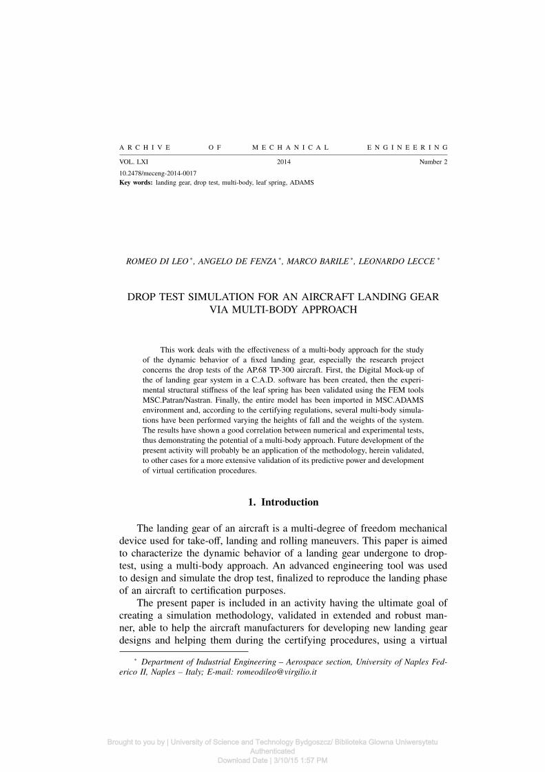
Finally, in the Table 1 the results of the static simulations for differentloads, compared to the experimental results [17] are presented. In Figure 6 thecomparison between the numerical and experimental stiffness is proposed.
Table 1.Numerical/Experimental comparison of spring leaf’s static analysis
load[N]
Numericaldeflection
[mm]
Experimentaldeflection
[mm]
Difference[%]
Numericalstiffness[Kg/mm]
Experimentalstiffness[Kg/mm]
Difference[%]
2270 15 13,8 8,7 15,4 16,8 -8,0
6810 46,7 43,8 6,6 14,9 15,8 -6,2
11350 79,7 75,0 6,3 14,5 15,4 -5,9
15890 113,1 113,7 -0,5 14,3 14,2 0,5
20430 145,2 150,1 -3,3 14,3 13,9 3,4
25030 176,4 192,5 -8,4 14,5 13,3 9,1
29510 204,2 235,2 -13,2 14,7 12,8 15,2
34050 231,3 280,1 -17,4 15,0 12,4 21,1
The numerical results obtained via FEM about the static deflections ofleaf spring, until medium-high loads, perfectly match compared with the ex-perimental one. Increasing the load over 27kN the FEM simulations become
Brought to you by | University of Science and Technology Bydgoszcz/ Biblioteka Glowna UniwersytetuAuthenticated
Download Date | 3/10/15 1:57 PM
294 ROMEO DI LEO, ANGELO DE FENZA, MARCO BARILE, LEONARDO LECCE
Fig. 6. Matching numerical/experimental stiffness of the leaf spring
less conservative, resulting in the higher rigidity of the entire landing gear.Then, the numerical leaf spring highlights higher stiffness compared withthe real one. The different behavior of the structure at high load conditionscould be due to change in the boundary conditions used in the experimentalcampaign and not reported in the literature report [15].
4. ADAMS model
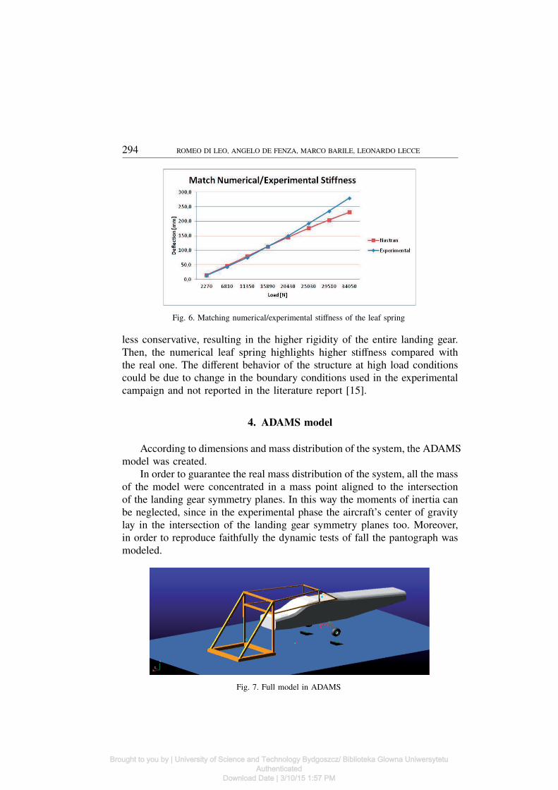
According to dimensions and mass distribution of the system, the ADAMSmodel was created.
In order to guarantee the real mass distribution of the system, all the massof the model were concentrated in a mass point aligned to the intersectionof the landing gear symmetry planes. In this way the moments of inertia canbe neglected, since in the experimental phase the aircraft’s center of gravitylay in the intersection of the landing gear symmetry planes too. Moreover,in order to reproduce faithfully the dynamic tests of fall the pantograph wasmodeled.
Fig. 7. Full model in ADAMS
Brought to you by | University of Science and Technology Bydgoszcz/ Biblioteka Glowna UniwersytetuAuthenticated
Download Date | 3/10/15 1:57 PM
DROP TEST SIMULATION FOR AN AIRCRAFT LANDING GEAR VIA MULTI-BODY APPROACH 295
All the steps useful to the multi-body modeling and then for the droptests simulation are described in detail below.
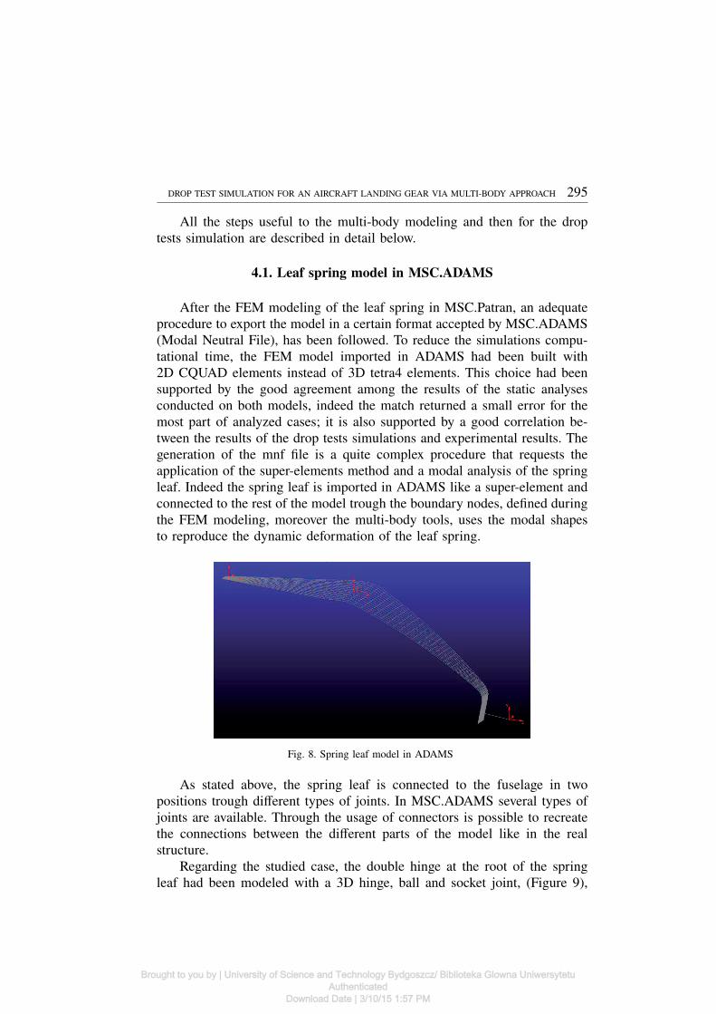
4.1. Leaf spring model in MSC.ADAMS
After the FEM modeling of the leaf spring in MSC.Patran, an adequateprocedure to export the model in a certain format accepted by MSC.ADAMS(Modal Neutral File), has been followed. To reduce the simulations compu-tational time, the FEM model imported in ADAMS had been built with2D CQUAD elements instead of 3D tetra4 elements. This choice had beensupported by the good agreement among the results of the static analysesconducted on both models, indeed the match returned a small error for themost part of analyzed cases; it is also supported by a good correlation be-tween the results of the drop tests simulations and experimental results. Thegeneration of the mnf file is a quite complex procedure that requests theapplication of the super-elements method and a modal analysis of the springleaf. Indeed the spring leaf is imported in ADAMS like a super-element andconnected to the rest of the model trough the boundary nodes, defined duringthe FEM modeling, moreover the multi-body tools, uses the modal shapesto reproduce the dynamic deformation of the leaf spring.
Fig. 8. Spring leaf model in ADAMS
As stated above, the spring leaf is connected to the fuselage in twopositions trough different types of joints. In MSC.ADAMS several types ofjoints are available. Through the usage of connectors is possible to recreatethe connections between the different parts of the model like in the realstructure.
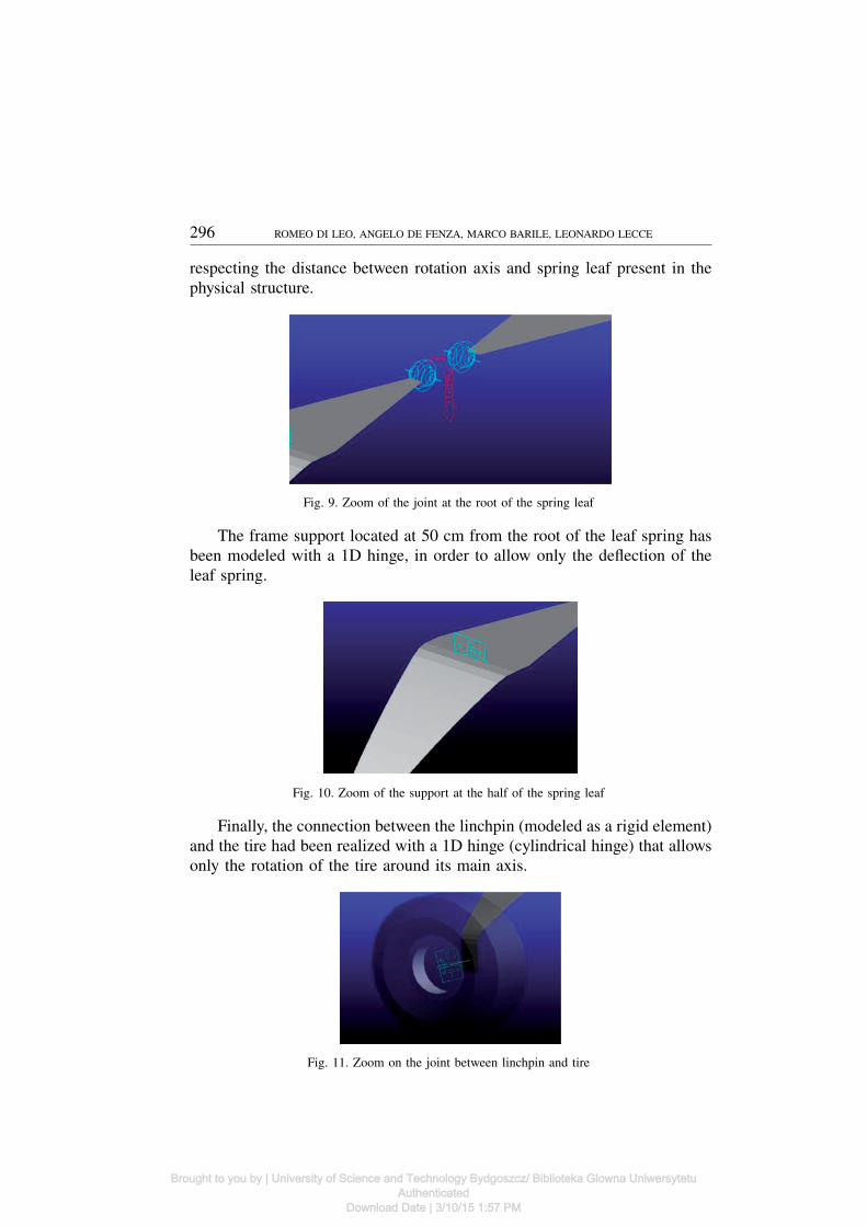
Regarding the studied case, the double hinge at the root of the springleaf had been modeled with a 3D hinge, ball and socket joint, (Figure 9),
Brought to you by | University of Science and Technology Bydgoszcz/ Biblioteka Glowna UniwersytetuAuthenticated
Download Date | 3/10/15 1:57 PM
296 ROMEO DI LEO, ANGELO DE FENZA, MARCO BARILE, LEONARDO LECCE
respecting the distance between rotation axis and spring leaf present in thephysical structure.
Fig. 9. Zoom of the joint at the root of the spring leaf
The frame support located at 50 cm from the root of the leaf spring hasbeen modeled with a 1D hinge, in order to allow only the deflection of theleaf spring.
Fig. 10. Zoom of the support at the half of the spring leaf
Finally, the connection between the linchpin (modeled as a rigid element)and the tire had been realized with a 1D hinge (cylindrical hinge) that allowsonly the rotation of the tire around its main axis.
Fig. 11. Zoom on the joint between linchpin and tire
Brought to you by | University of Science and Technology Bydgoszcz/ Biblioteka Glowna UniwersytetuAuthenticated
Download Date | 3/10/15 1:57 PM
DROP TEST SIMULATION FOR AN AIRCRAFT LANDING GEAR VIA MULTI-BODY APPROACH 297
4.2. Tire and road definition in ADAMS
The dynamic behavior of the landing gear during the drop-test are strong-ly influenced by the interaction between tires and ground, for this reason anaccurate modeling of these two parts is very important.
Besides helping to provide a smooth ride, the function of a pneumatictire is to transmit forces and moments in three mutually perpendicular direc-tions for vehicle direction control. A great number of tests and mathematicalmodels have been developed to understand and predict the behavior of atire [18]. In literature these models are classified in four groups: complexphysical model, simple physical model, similarity methods and model basedonly on experimental data (so called empirical model) [19].
Physical model are addressed to model tire performance rather than itsbehavior in relation to the dynamic of the vehicle. This type of models hasparameters such as materials, construction, geometry, tread design, loads. Inparticular complex physical models generally use finite element modelingtechniques. Finite elements models of the tire are of particular interest whenconsidering the interaction between the tire and road irregularities and forinvestigation between the road and the tire within the footprint of the tire[20].
Model based on similarity methods were useful early in the tire forcemodel development process but they have found less use recently as theyhave been superseded by utilities given by other models [19].
The two remaining model classifications are the simple physical modeland the empirical models. They relate the physical and kinematic propertiesof tires to the development of forces at the contact between tire and theroadway surface. In particular one of the most used simple physical modelis the brush one. Brush models have been improved and developed overthe recent years [21] but have not yet found their way in many dynamicsimulation programs.
The remaining tire model class is the empirical model. This type ofmodels employs mathematical functions capable of emulating the highlynon linear behavior of the force generated by the tires. These mathematicalfunctions can range from straight line segment approximations to nonlinearfunctions that contain numerous coefficients based on experimental data. Thistype of models is widespread in the vehicle dynamics simulation software.In the empirical models, the longitudinal tire force typically is mathemat-ically expressed as a function of a variable called slip ratio. The lateraltire force typically is mathematically expressed as a function of a variablecalled slip angle. A third, distinct, feature of these models is the method ofproperly combining these two forces components for conditions of combined
Brought to you by | University of Science and Technology Bydgoszcz/ Biblioteka Glowna UniwersytetuAuthenticated
Download Date | 3/10/15 1:57 PM

298 ROMEO DI LEO, ANGELO DE FENZA, MARCO BARILE, LEONARDO LECCE
slip ratio and slip angle. Empirical models generally neglect effects such asself-aligning torque, camber steer, ply steer.
The chosen tire model is the FIALA one [22] that in literature is oftenused for drop test simulation purposes. FIALA model uses some empiricalrelations to calculate the force generated between tire and ground. Thesemathematic relations are function of slip ratio and slip angle. The backgroundof the FIALA tire model is a physical tire model in fact analytical relationsare derived from a physical tire model where carcass is modeled as a beamon elastic foundation. Elastic brush elements provide the contact betweencarcass and road.
The only available experimental and technical information about the typeof tire used during the tests are the load-deflection curves (dependent fromthe inflation pressure that is 54 PSI for the studied case) and some geomet-rical and technical features. Parameters which mostly influence results of thesimulations are the vertical damping (the stiffness depends on the inflationpressure), and the tire and ground friction’s parameters. The solver used aspecific equation to calculate the friction coefficient:
U = Umax − (Umax − Umin) SSα (1)
where:Umax and Umin are the friction coefficients respectively in conditions of nullslip ratio and slip ratio equal to one, SSα is the comprehensive slip, definedas:
SSα =
√S2
S + (tan α)2 (2)
where SS and α are respectively the slip ratio and the slip angle. It is importantto remember that the slip ratio SS is given by:
SS = −Vx − re
Vx(3)
where Vx is the longitudinal component of the total velocity vector V of thewheel center and re is the effective rolling radius. Finally the slip angle αis the angle formed between the direction of velocity vector of the centerof the tire contact patch and the ISO-W x axis (this axis is defined as theintersection of the wheel plane and the local road plane) [22].
The value for these parameters was initially chosen by reference values,selected in relation to the physical experimental conditions; afterwards, con-sidering that there is real rate of indetermination work of tuning has been car-ried out to find out the values that give back a good numerical/experimentalcorrelation.
Brought to you by | University of Science and Technology Bydgoszcz/ Biblioteka Glowna UniwersytetuAuthenticated
Download Date | 3/10/15 1:57 PM

DROP TEST SIMULATION FOR AN AIRCRAFT LANDING GEAR VIA MULTI-BODY APPROACH 299
All the tire’s geometrical and technical parameters must be defined ina text file with a specific format accepted by ADAMS, while tire’s massproperties and location must be specified in the ADAMS/tire tab.
Regarding the road construction, besides the geometrical information,for the chosen model of road, only the correction factor for the frictioncoefficient, “mu” must be defined. This factor is multiplied for the coeffi-cient of friction U defined before; the result is the final friction coefficientacting between tire and road. To simulate the presence of lubricated wedges,the chosen value for mu has been found out thanks to the work of tuningmentioned before [23].
4.3. Pantograph modeling
The pantograph model is based on the technical scheme reported inFigure 2 and on the table present in [17], shown in Figure 12, where thedimensions of each part of the structure are reported.
Fig. 12. Table with the pantograph components’ characteristics
Fig. 13. Zoom on the pantograph model in ADAMS
Brought to you by | University of Science and Technology Bydgoszcz/ Biblioteka Glowna UniwersytetuAuthenticated
Download Date | 3/10/15 1:57 PM

300 ROMEO DI LEO, ANGELO DE FENZA, MARCO BARILE, LEONARDO LECCE
The hinges that connect the pantograph’s arms with the support fixed tothe ground and the cage fixed to the fuselage had been modeled with a setof 1D hinges properly oriented. It has been made to simulate a dynamic offall very close to the one obtained during the tests.
4.4. Simulations settings and results
The experimental tests, as stated above, had been carried out followingthe normative indications. These last impose weight and height of fall forthe complex, depending from the maximum landing weight of the aircraft.In the model, the weight variation is obtained modifying the value of theconcentrated mass, while the height of fall variation is obtained changingthe initial rotational angle in one of the pantograph’s hinges.
In the table below the simulations’ results for different set-up are reportedand compared with the respective experimental results.
Table 2.Numerical/Experimental comparison
Tire Damping = 9(N*sec)/mm mu = 0,15 C alpha = 35N/deg UMIN = 1 UMAX = 1
Table about Numerical/Experimental Drop test
Weight ofthe system(Max Load)
(kg)
Height offalling (mm)
Angleof
Chock(◦)
Load Factor Diff. % Deflection Diff. %
Experi-mental
Numeri-cal
Experi-mental
Numeri-cal
1774(2470) 470 (Limit) 16 3,90 3,87 -0,8 360 329 -8,6
1774(2470) 350 16 3,38 3,47 2,7 295 288 -2,4
1774(2470) 250 16 2,90 3,12 7,6 225 250 11,1
1564(2470)
677 (Reserveenergy) 16
Notrecorded – – 395 353 -10,6
1819(2565) 470 18,5 4,15 3,83 -7,7 365 336 -7,9
Moreover, by the way of example, in the figures below are showed curvesabout acceleration and deflection, obtained by simulation and used to obtainresults, reported in the Table 2 (in the particular case respectively rows n◦ 1and 4) and the experimental curves, measured during the drop test.
Brought to you by | University of Science and Technology Bydgoszcz/ Biblioteka Glowna UniwersytetuAuthenticated
Download Date | 3/10/15 1:57 PM

DROP TEST SIMULATION FOR AN AIRCRAFT LANDING GEAR VIA MULTI-BODY APPROACH 301
Fig. 14. Experimental/Numerical match about acceleration of CM (h. 470mm W. 2470Kg LimitDrop Test)
Fig. 15. Experimental/Numerical match about deflection of CM (h. 470mm W. 2470Kg LimitDrop Test)
Fig. 16. Experimental/Numerical match about acceleration of CM (h. 677mm W. 2470KgReserve Energy Absorption Drop Test)
Brought to you by | University of Science and Technology Bydgoszcz/ Biblioteka Glowna UniwersytetuAuthenticated
Download Date | 3/10/15 1:57 PM

302 ROMEO DI LEO, ANGELO DE FENZA, MARCO BARILE, LEONARDO LECCE
Fig. 17. Experimental/Numerical match about deflection of CM (h. 677mm W. 2470Kg ReserveEnergy Absorption Drop Test)
5. Conclusions
This activity was aimed to reproduce the experimental results of thedrop tests, conducted on the general aviation aircraft Partenavia AP.68TP-300 Spartacus via a multi-body simulation approach. The procedure followedto pursue the objective, starting from the geometric description of the prob-lem, the FEM modeling and up to the final results obtained, was largelydescribed in the previous sections. A validation of the structural stiffnessof the leaf spring model through non-linear static simulations using Nastransolver were performed in order to correctly define the multi-body model.About the static deflections of leaf spring, the numerical results obtained viaFEM, until medium-high loads, perfectly match compared with the experi-mental one. Increasing the load over 27kN the FEM simulations become lessconservative, resulting in the higher rigidity of the entire landing gear. Then,the numerical leaf spring highlights higher stiffness compared with the realone. Once the multi-body model was realized a drop tests were simulatedaccording to the 14 Code of Federal Regulation (CFR) Part 23. The numer-ical results showed a percentage error variable from 1% to 11%, in terms ofdeflection and load factor. Based on these results the proposed methodologyhighlights an excellent reliability. In addition, the proposed approach resultsflexible and applicable to the main landing gear of any other general aviationaircraft.
Acknowledgments
Our acknowledgments are addressed to Vulcanair Company for the greatsupport and availability throughout the activity. A particular acknowledgment
Brought to you by | University of Science and Technology Bydgoszcz/ Biblioteka Glowna UniwersytetuAuthenticated
Download Date | 3/10/15 1:57 PM
DROP TEST SIMULATION FOR AN AIRCRAFT LANDING GEAR VIA MULTI-BODY APPROACH 303
is addressed to eng. Sergio Severo, Head of Design Organization of VulcanairCompany for his help and courteous availability.
Manuscript received by Editorial Board, December 04, 2013;final version, May 04, 2014.
REFERENCES
[1] 14 Code of Federal Regulation Part 23.725 Amdt. 6[2] 14 Code of Federal Regulation Part 23.727 Amdt. 6[3] Kruger W.R. et al.: Aircraft Landing Gear Dynamics: Simulation and Control. Vehicle System
Dynamics, 28, 1997, pp. 257-289.[4] Doyle G.A.: A Review of Computer Simulations for Aircraft-surface Dynamics. Journal of
Aircraft, 23 (4), 1986.[5] Catt T., Cowling D., and Shepherd A.: Active Landing Gear Control for Improved Ride
Quality during Ground Roll. Smart Structures for Aircraft and Spacecraft (AGARD CP 531).Stirling Dynamics Ltd., Bristol, 1993.
[6] Bakker E., Nyborg L., Pacejka H.B.: A New Tyre Model With an Application in VehicleDynamics Studies. SAE 890087, 1998.
[7] Hitch H.P.Y.: Aircraft Ground Dynamics. Vehicle System Dynamics. 10, 1981, pp. 319-332.[8] Kruger W.R. et al.: Aircraft Landing Gear Dynamics: Simulation and Control. Vehicle System
Dynamics, 28, 1997, pp. 257-289.[9] Pritchard J.: An Overview of Landing Gear Dynamics. NASA Langley R. C.,/TM-1999-
209143, ARL-TR-1976, May 1999.[10] Schlippe B. V., Dietrich R.: Das Flattern des pneumatischen Rades. Lilienthal Gesellschaft
fur Luftfahrtforschung, 1941.[11] Pacejka H.B.: Tire Models for Vehicle Dynamics Analysis. In: 1st International Colloquium
on Tire Models for Vehicle Dynamics Analysis. Swets & Zeitlinger, 1991.[12] Bakker E., Nyborg L., Pacejka H.B.: A New Tyre Model With an Application in Vehicle
Dynamics Studies. SAE 890087, 1989.[13] Pacejka H.B., and Besselink I.J.M.: Magic Formula Tyre Model with Transient Proper-
ties,Vehicle System Dynamics Supplement 27, 1997, pp. 234-249.[14] Rook T., Kumar S.: Dynamic Aircraft Landing Gear Simulation Using Flexible Multibody
Dynamics Methods in Adams to Guide Component Design and Testing. ADAMS User Con-ference, June 2010.
[15] Giordano V., Pascale L.: Partenavia AP68 - Consuntivo Prove di Caduta: Carrello Principale.Ufficio Tecnico Vulcanair S.p.a.
[16] Giordano V., Pascale L.: Partenavia AP68 - Preventivo Prove di Caduta: Carrello Principale.Ufficio Tecnico Vulcanair S.p.a.
[17] Concilio R., Verde G.: Studio teorico sperimentale sul comportamento dinamico del carrelloa balestra di un velivolo biturbina dell’aviazione generale. Tesi di Laurea Universita di NapoliFederico II a.a. 1981/82.
[18] Brach Raymond M., Brach R. Matthew: Tire Models for Vehicle Dynamic Simulation andAccident Reconstruction, AE Technical Paper 2009-01-0102, 2009, doi:10.4271/2009-01-0102.
[19] Pacejka Hans: Tire and vehicle Dynamics, SAE, Warendale, PA, 2002.[20] Tonuk E., Unlusoy Y. S.: Prediction of automobile tire cornering force characteristics by finite
element modeling and analysis, Computers and Structures, 79, 2001, pp 1219-1232.[21] Gafvert M., Svedenius J.: Construction of Novel Semi-Empirical Tire Models for Combined
Braking and Cornering, Lund Institute of Technology, Sweden 2003, ISSN 0280-5316.
Brought to you by | University of Science and Technology Bydgoszcz/ Biblioteka Glowna UniwersytetuAuthenticated
Download Date | 3/10/15 1:57 PM

304 ROMEO DI LEO, ANGELO DE FENZA, MARCO BARILE, LEONARDO LECCE
[22] Msc Software ADAMS/ Tire Guide. www.mscsoftware.com[23] Di Leo R., De Fenza A., Barile M., Moccia D., Lecce L.: “Multi-body approach to the
simulation of particular drop test for an aircraft landing gear”, Proceedings of the ECCOMASThematic Conference on Multibody Dynamics, pp. 23-33, 2013.
Zastosowanie metody układów wieloczłonowych do symulacji wypuszczaniapodwozia w samolocie
S t r e s z c z e n i e
Praca dotyczy efektywności analizy dynamicznej stałego podwozia samolotu wykonanej przypomocy oprogramowania dla układu wieloczłonowego. Przedstawiono dowód zgodności międzysymulacją numeryczną a wynikami eksperymentalnych testów spadowych dla samolotu AP.68TP-300.
Po wykonaniu makiet cyfrowych głównych części składowych podwozia w oprogramowa-niu C.A.D. 3D, importowano je do środowiska ADAMS i zmontowano wirtualnie by odtworzyćrzeczywiste więzy. W środowisku ADAMS zrealizowano także model obiektu testowego.
Kadłub samolotu i podstawowe części podwozia zostały zamodelowane jako ciało sztywne.Jedynie resor piórowy i opona były symulowane jako ciała elastyczne. W symulacji wykorzystanomodel opony ze środowiska ADAMS dodając informację o podłożu z pliku danych drogowych.Opracowano symulacje mające odtworzyć przebieg doświadczalnego testu spadowego, scharak-teryzowany przez określoną masę i wysokość spadku. Wyniki wykazały dobrą korelację międzysymulacją cyfrową i testem doświadczalnym, co stanowi wstępny dowód możliwości przyszłejredukcji kosztów dzięki wirtualnej certyfikacji nowych opracowań podwozi samolotowych.
Przyszły rozwój prowadzonych obecnie badań będzie prawdopodobnie iść w kierunku zas-tosowania tej metodologii do innych przypadków, co pozwoli na szerszą walidację mocy predyk-cyjnej metody. Będzie także opracowana wirtualna procedura certyfikacji.
Brought to you by | University of Science and Technology Bydgoszcz/ Biblioteka Glowna UniwersytetuAuthenticated
Download Date | 3/10/15 1:57 PM